

Haier HFD647AS, HB21TSSAA Service Manual
Order No. Ref1104S002V0
◎2011 (HAIER ELECTRICAL APPLIANCES COR. LTD)
All right reserved. Unauthorized copying and distribution is a violation of law.
Refrigerator
SERVICE MANUAL
MODEL: HFD647AS
HB21TSSAA
This service information is designed for experienced repair technicians only and is not designed for use b y the general public. It
dose not contain warnings and cautions to advice non-technical individuals of potential dangers in attempting to service a product.
Product powered by electricity should by serviced or repaired only by experienced professional technicians. Any attempt to service
or repair the product or products dealt with in this service information by anyone else could result in serious injury or death.
Haier Group
WARNING

SERVCE MANUAL
Model:HFD647AS/HB21TSSAA
2
Contents
Table of Contents ·········································································································· 1
1. General Information·································································································· 4
1-1. General guideline ······························································································· 4
1-2. Insurance test····································································································· 4
1-3. How to read this Service Manual········································································ 5
2. Product Feature ········································································································ 6
2-1. Specifications ····································································································· 6
2-2. Main Functions··································································································· 7
2-3. External views ···································································································· 8
2-4.How to use the crisper ························································································9
2-5.How to use the Delicatessen drawer 9
3.
Disassembly
············································································································ 10
3-1. Installing the Door Handle················································································ 10
3-2. Installing and Removing Door ·········································································· 12
3-3.
Removing and installing Lower Freezer Drawer (If required)··························· 13
3-4. Water line installation ······················································································· 14
3-5. Kick plate installation ························································································ 15
3-6. Height-adjustable shelf ····················································································· 15
3-7.
Removing Crisper Cover·················································································· 16
3-8.Replacing the light bulb (Refrigerator)······························································· 16
4. Control and display system ·······················································································17
4-1. Control display board························································································ 17
4-2. Artificial intelligence setting ·············································································· 17
4-3. Locking / Unlocking setting··············································································· 17
4-4. Quick freezing setting······················································································· 17
4-5.Quick refrigerating setting ··················································································18
4-6. Switch off ice-maker ··························································································18
4-7. Quick ice-making function·················································································18
4-8.Te mperature setting and adjustment ·································································19

SERVICE MANUAL
Model: HFD647AS/HB21TSSAA
3
4-9. Door-open warning······················································································· 19
4-10. Energy saving display ·················································································· 19
4-11.Power off memory························································································19
4-12. Time adjustment and display ·······································································19
4-13. Ambient temperature display ······································································· 19
5.
Control principle and related test functions·························································· 20
5-1. Air Damper······································································································ 20
5-2. Control principle of fan motor·········································································· 20
5-3. Defrost control principle ·················································································· 20
5-4. Ice- making process ························································································21
5-5. Self-testing Function 22
5-6. Ice-maker Inspection Mode 23
6. System flow principle······························································································· 24
6-1. System flow scenograph················································································· 24
6-2. System flow chart···························································································· 24
7. Circuit diagram·········································································································· 25
7-1. Main control PCB diagram·············································································· 25
7-2. Brief principle diagram ···················································································· 27
7-3.Sensor and error code ····················································································· 28
7-4.
Display Error Codes Information ····································································· 28
8. Water line map ··········································································································· 29
8-1.Th e water line sketch map ···············································································29
8-2.Water line scenograph ·····················································································30
8-3.
Water inlet quantity setting (HFD647A*) 30
9. Trouble shooting ·······································································································31
9-1.Frequently problems·························································································31

SERVICE MANUAL
Model: HFD647AS/HB21TSSAA
4
Chapter 1 General Information
1-1. General Guidelines
When servicing, observe the original lead dress. If a short circuit is found, replace all parts which have
been overheated or damaged b y the short circuit. After servicing, see to it that a ll the protective devices
such as insulation barriers, insulation p apers shields are pro perly installed. After servicing, make the
following leakage current checks to prevent the customer from being exposed to shock hazards.
1) Leakage Current Cold Check
2) Leakage Current Hot Check
3) Prevention of Electro Static Discharge (ESD) to Electrostatic Sensitive
1-2. Insurance test
1. Check if there is any leak of current.
2. Cut out the power supply before the repair to avoid an electrical shock hazard.
3. In the case of a live-line test, insulating gloves should be worn to avoid potential electrical shock.
4. Confirm the rated current, voltage and capacity before testing with any kinds of instruments.
5. Watch if the upper door is open when you check something at a lower position.
6. Take out every part in the cabinet before moving the machine, especially things like panels (e.g. glass
shelf).
7. Please wear intact cotton gloves when repair any parts of the evaporator, so that scratches by the
sharp finscan be avoided.
8. If there is a breakdown with the refrigeration system, please surrender the machine to the service
center, else the leaked refrigerant may pollute the atmosphere.
9. The refrigerator use AC of 220V with a frequency of 50Hz.
10. A big fluctuation of voltage (exceed the range 187~242V) may cause a start failure of the refrigerator,
a burn -out o f the control p anel and compressor, or an abn ormal sound from the compressor in
operation. In this condition an automatic voltage regulator over 750W should be added.
11. Take care not to damage the supply line. Don’t yank at the line; pull the plug out gently from the
receptacle. Don’t press the line under the cabinet or step on it. Take care not to roll on or damage the
supply line when moves the machine from the wall.
12. In the case of leakage of inflammable gases like carbon monoxide, open the door and windows. Don’t
pull out or insert the plugs of the appliance.
13. Don’t touch the refrigeration surface of the freezing compartment when the refrigerator is in operation,
especially when your hand is wet, else you may be glued to the surface.
14. Pull out the plug of power suppl y du ring clearan ce or power out age. Wait at least five minutes to
resume the power supply in order to prevent damage to the compressor caused by continuous restart.
SERVICE MANUAL
Model:HFD647AS/HB21TSSAA
5
Photo used in this manual
The illustration and phot os used in this Manual may not base on the final design of products, which may
differ from your products in some way.
1-3. How to read this Service Manual
1-3-1. Using Icons
The meaning of each icon is described in the table below:
Note:
A “note” provides information that is not indispensable.
Caution:
A “caution” is used when there is danger, through incorrect manipulation, may damage equipment, loose
data, get an unexpected result or has to restart (part of) a procedure.
Warning:
A “warning” is used when there is danger of personal injury.
Reference:
A “reference” guides to find additional information on a specific topic.
SERVICE MANUAL
Model: HFD647AS/HB21T SSAA
6
Chapter 2 Product Feature
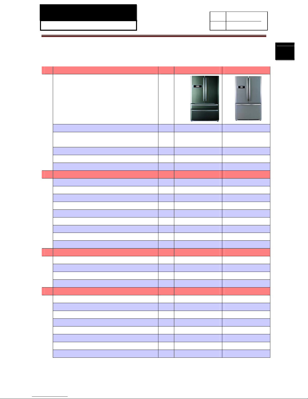
2-1. SPECIFICATIONS
1 Model
HFD647AS
H B21T SSAA
Photo
Product description (Refrigerator/Freezer) Refrigerator-Freezer Refrigerator-Freezer
Type of ap pliance (FS=free standing / BI= FS FS
built-in)
Type of cooling system(NF=no frost/ S=static) NF NF
Climate class*
Freezer compartment / Star rating 4* 4*
2 Key features
Total gross volume
Total storage volume L 518 507
Defrosting (M=manual A=autom atic) A A
Energy consumption / year
Frost free system yes yes
Defrost water outlet yes yes
Air circulating ventilator yes yes
Kind of coolant R134a/ 160g R 600a/ 75g
Foaming components
C-P
C-P
3 Technical data
Voltage / frequency V/Hz 220V-240V~/ 50 220V-240V~/ 50
Temperature range (from>to) °C
-22 ~ 7
-22 ~ 7
Input power W 220 220
Cooling system: K=Compressor / A=Absorption
K K
4 Door:
F= flat / R= rounded / S= streamline S S
Inside color w w
Hinged (r =right l =left) / reversible R / L R / L
Freezing compartment integrated with door Yes Yes
Shelves:
Number Fridge / Freezer
4 / - 3 / -
Type (gr=grill / g=glass / p=plastic)
g / P g / P
Color w-white / g=green / t=transparent.
t
t

SERVICE MANUAL
Model: HFD647AS/HB21TSSAA
7
Adjustable (Y=yes / N=not)
Yes Yes
Drawers:
Plastic drawers (fully freezing comp.) n°. 2 1
Half freezing comp n°. 2 2
Color of drawer (w=white/t=transp./g=green) w/t w/t
Crisper:
Chiller / Meat (salad crisper) transparent / white Chiller (t) Chiller (t)
Vegetable crisper(s) transparent / white t t
5 Equipment & accessories
Con trol panel:
Interior / exterior Interior Interior
Thermometer interior / exterior Interior Interior
Over temperature alarm LED / acoustic Yes Yes
Adjustable thermostat Yes Yes
Fast freeze switch /-function Yes Yes
Deodorizing Yes Yes
Interior light W Yes Yes
Freeze pack(s) n° 2 2
ice maker Manual/ Automatic A M
Ice cube tray(s) n° 1 1
Adjustable feet front / rear n° 2 /FRONT 2 /FRONT
Castors front / rear -/yes -/yes
Length of cable/incl. plug cm 245 245
Condenser Back / Integrated B B
6 Product dimensions
Unit dimensions ( H / W / D) cm 177/91/75 177/91/75
Net weight kg 135 130
7 Packing dimensions & load ability
Packing dimensions (H / W / D) cm 186/98/76 186/98/76
Gross weight kg 148 143
8 Service
User manual English English
2-2. Main Functions
◆ Removable automatic icemaker
◆ Foldaway wine holder.
◆ Large crisper with humidity adjustment.
◆ Holiday function.
◆ Fridge storage compartment can be set on/off separately.
◆ Intelligent alarm function: automatic alarm at over temperature, malfunction, door open.
SERVICE MANUAL
Model: HFD647AS/HB21TSSAA
8
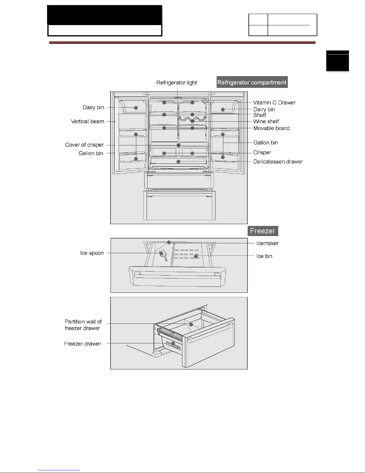
2-3. External views
SERVICE MANUAL
Model: HFD647AS/HB21TSSAA
9
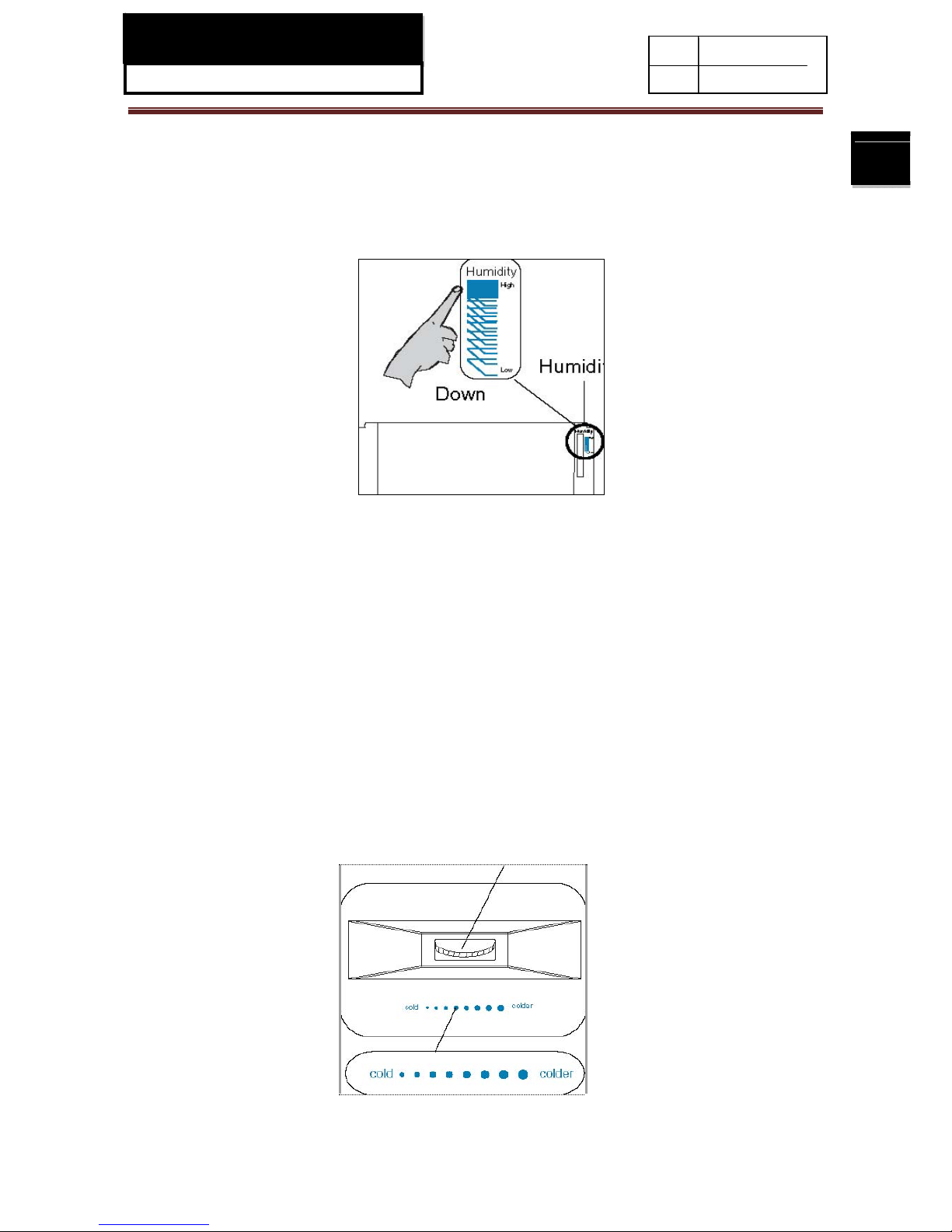
2-4. How to Use the Crisper
The appliance is equipped with a crisper for vegetable and fruit storage. You can set the humidity to
meet your storage needs.
1.
Turn the humidity regulator (located at the upper right Humidity regulator corner of the crisper) up
to get a higher humidity suitable for storage of cucumber, grape, kiwifruit and persimmon etc.
2. Turn the humidity regulator (located at the upper right corner of the crisper) down to get a lower
humidity suitable for storage of strawberry, orange, bean, garlic, watermelon, plum and tomato etc.
2-5. How to Use the Delicatessen Drawer
The appliance is equipped with a delicatessen drawer with a temperature range
from-2°C~+3°C.The temperature can be adjusted by the air control knob to meet your storage needs.
1. Turn the air control knob left (weak) to reduce the cooled air moving in the delicatessen drawer
and maintain a higher temperature;
2. Turn the air control knob right (strong) to increase the cooled air moving in the delicatessen
drawer and maintain a lower temperature.
SERVICE MANUAL
Model: HFD647AS/HB21TSSAA
10
Chapter3 Disassembly
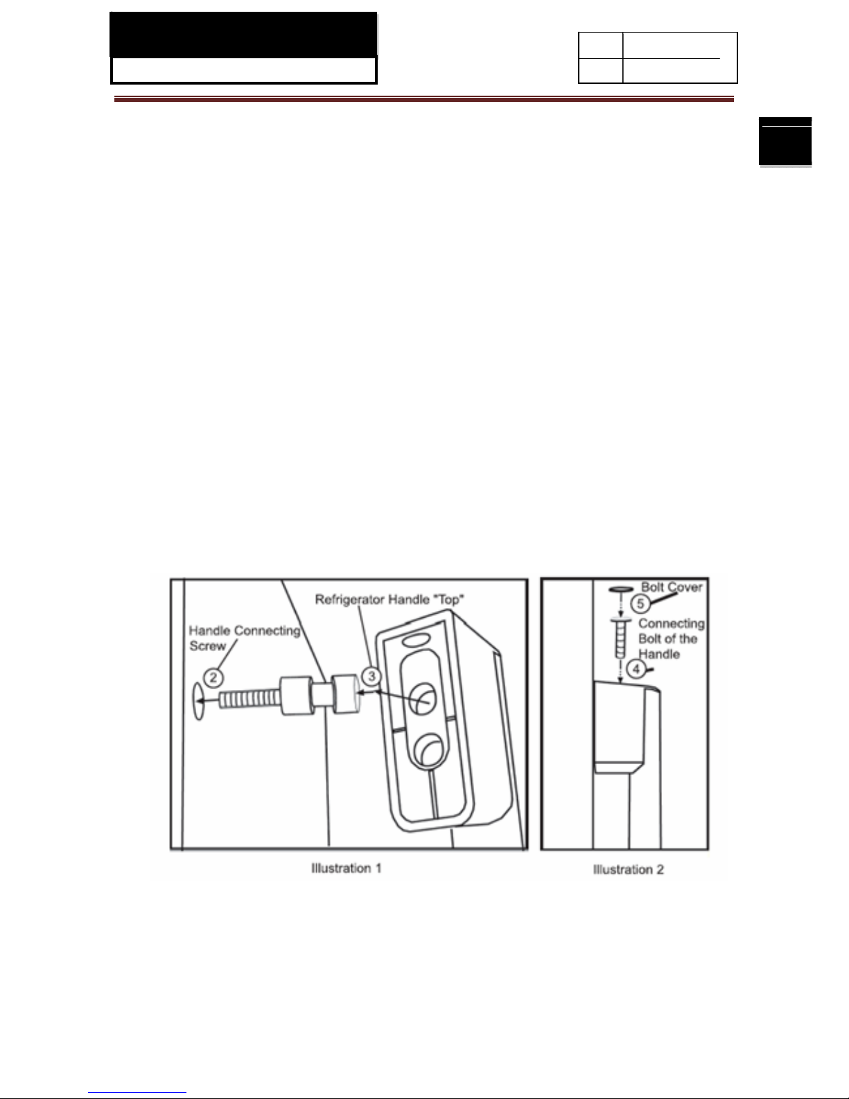
3-1. Door handle installation
3-1-1.Refrigeration door handle
1. Retrieve the handle clearly marked for the Refrigerator Door that needs attachment.
2. Insert the Handle Connecting Screws into the holes provided on the Refrigeration Door. Using a hand
held screwdriver tighten the Handle Connecting Screw until the screw threads disappear and the first
flat surface of the Handle Connecti ng Screw tou ches the Refrigerat or Do or surface ( as shown in
illustration1- step2). Do not over tighten-damage to the door can occur.
3. Place the Refrigeration Door Handle onto the Handle Connecting Screws using the upper hole of the
“Top” Refrig eration Doo r Handle (as shown in il lustration 1-step3); The Refrigeration Door Handle
should rest comfortably to the door on these Connecting Screws.
4. Insert the Connecting Bolt into the hole at the top of the Refrigerator Door Handle. Using the provided
Hex Driver and tighten until the handle is fixed firmly to the door. Repeat this process for the “Bottom”
of the Refrigeration Door Handle (as shown in illustration 2-step4) .Be careful when tightening not to
scratch the door surface.
5. Place Bolt Covers into the holes on the handle at the top and bottom and push into place (as shown in
illustration2- step5).
6. To disassemble the Refrigeration Door Handle, follow these directions in reverse.
 Loading...