

Haier HARECTWODW303 Installation manual
Installation Instructions
IMPORTANT: Save for local electrical inspector’s use.
IMPORTANT: Conserver pour consultation par l’inspecteur local des installations électriques.
IMPORTANTE: Guárdelo para uso del inspector eléctrico local.
Instructions d’installation
Instrucciones de instalación
HCC2220BEB
24" Electric Radiant Cooktop
Table de cuisson électrique radiante de 24"
Supercie de cocción eléctrica radiante de
24"
Part # 0060522885 Rev A


TABLE OF CONTENTS
COOKTOP SAFETY .............................................................................. 2
INSTALLATION REQUIREMENTS ............................................................. 2
Tools and Parts ............................................................................. 2
Location Requirements ................................................................... 3
Electrical Requirements .................................................................. 5
INSTALLATION INSTRUCTIONS ............................................................. 6
Step 1 - Unpack Cooktop ................................................................. 6
Step 2 - Prepare for Installation ......................................................... 6
Step 3 - Install Cooktop ................................................................... 7
Step 4 - Make Direct Wire Electrical Connection .................................... 8
Step 5 - Complete Installation ........................................................ 11
ENGLISH
1
Read all safety instructions before using the product. Failure to follow these
instructions may result in fire, electrical shock, serious injury or death.
PARTS NEEDED
UL Listed Strain Relief
•
UL Listed Wire Connectors
•
Check local codes. Check existing electrical supply. See the appropriate “Electrical
Requirements” section. It is recommended that all electrical connections be made
by a licensed,
electrical installer.
LOCATION REQUIREMENTS
IMPORTANT: Observe all governing codes and ordinances. When installing
cooktop, use minimum dimensions given.
To eliminate the risk of burns or by reaching over heated surface units,
•
cabinet storage space located above the surface units should be avoided. If
cabinet storage is to be provided, the risk can be reduced by installing a range
hood or microwave hood combination that projects horizontally a minimum of 5"
(12.7 cm) beyond the bottom of the cabinets.
The cooktop must be a cooktop that is approved to be installed either
•
alone or over an undercounter built-in oven.
Ovens approved for this type of installation will have an approval label located on
•
the top of the oven. If you do not this label, contact your dealer to
that your oven is approved. Refer to oven manufacturer’s Installation Instructions
for approval for built-in, undercounter use and required cutout dimensions.
The cooktop must be installed in a level countertop.
•
The cooktop should be installed away from strong draft areas, such as windows,
•
doors, fans or strong heating vents. The cooktop should be located for
convenient use in the kitchen.
Use the countertop opening dimensions that are given with these Installation
•
Instructions. Given dimensions are minimum clearances and provide 0" (0 cm)
clearance.
Grounded electrical supply is required. See “Electrical Requirements” section.
•
IMPORTANT: To avoid damage, check with your builder or cabinet supplier to make
sure that the materials used will not discolor, delaminate or sustain other damage.
• For Personal Safety, remove house fuse or open circuit breaker before beginning
installation. Failure to do so could result in serious injury or death.
• Be sure your cooktop is installed properly by a qualified installer or service technician.
• Make sure the cabinets and wall coverings around the cooktop can withstand the
temperatures (up to 200°F) generated y the cooktop.
Always disconnect the electrical service to the cooktop before repairing or servicing the
cooktop. This can be doe by disconnecting the fuse or circuit breaker. Failure to do this
could result in a dangerous or fatal shock. Know where your main disconnect switch is
located. If you do not know, have your electrician show you.
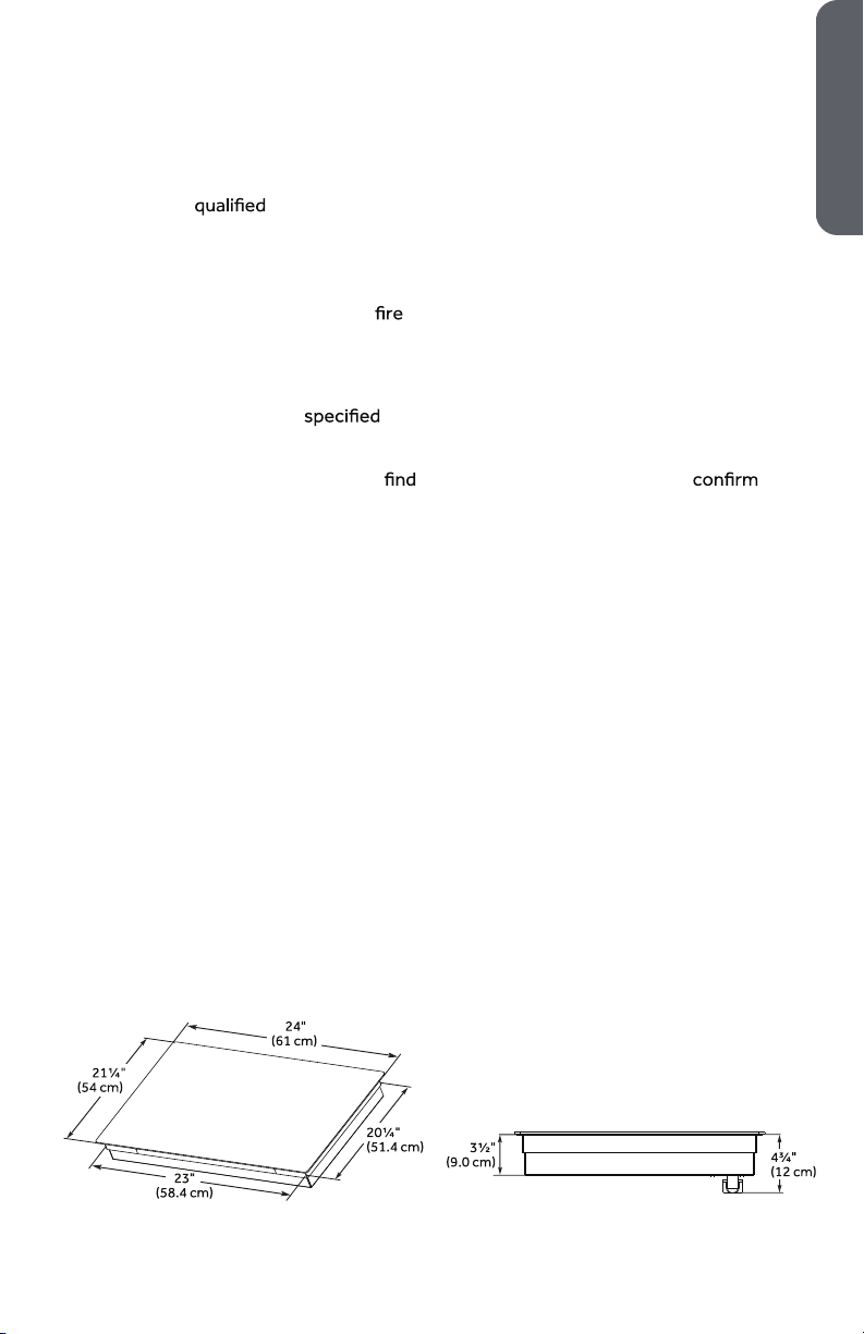
PRODUCT DIMENSIONS
ENGLISH
3
ENGLISH
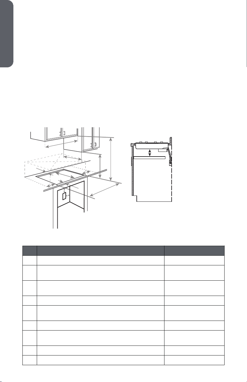
OPENING DIMENSIONS
This cooktop has been designed to accommodate a wide range of cutout sizes to
allow possible replacement with other brands. For a new installation, we recommend
that you consider the minimum dimension of cutout size.
NOTE:
If installing a range hood or microwave hood combination above the
•
cooktop, follow the range hood or combination microwave hood installation
instructions for the required clearance above the cooktop surface.
When installing the cooktop over a base cabinet, use a base cabinet with
•
sidewalls wider than the cutout requirements to avoid needing to notch
down the base cabinet sidewalls to clear the cooktop base.
If the base cabinet has a drawer, a 5¹⁄₂" (14.0 cm) depth clearance from the
•
top of the countertop to the top of the drawer (or other obstruction) in the
base cabinet is required.
5"
”
Description Dimension
(A) Width of the cooktop 24" (60.9 cm)
(B) Combustible area above countertop 19¹⁄₄" (49.0 cm) 19¹⁄₂"
(49.7 cm)
(C) Minimum clearance between top of cooktop and
30" (76.2 cm)
a
bottom of uncovered wood or metal cabinet.
(D) Recommended overhead cabinet depth 18" (45.7 cm) min
(E) Minimum clearance between front edge of
2" (5.1 cm)
countertop and front edge of cooktop
(F) Depth of cooktop opening 20⁵⁄₁₆" (51.7 cm)
(G) Min. height from countertop to nearest cabinet on
15" (38 cm)
either side of the cooktop
(H) Junction box: minimum from top of countertop 7" (17.8 cm)
(I) Junction box: maximum from right side of cabinet 9" (23.0 cm)
4
2" (5.08 cm)
ENGLISH
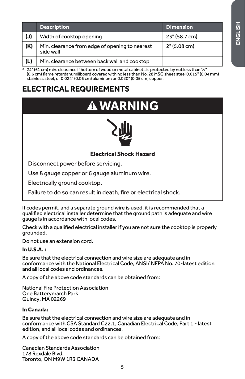
ELECTRICAL CONNECTION REQUIREMENTS
•
•
•
•
•
•
INSTALLATION INSTRUCTIONS
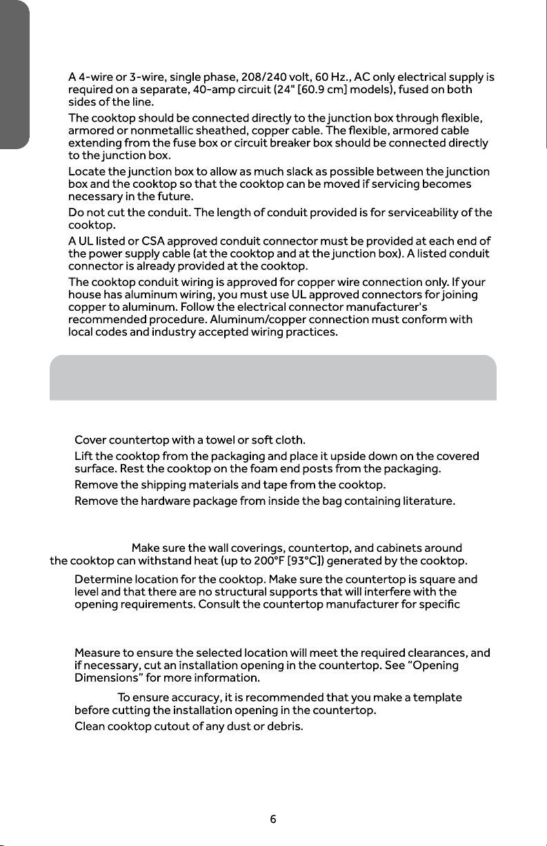
STEP 1 - UNPACK COOKTOP
1.
2.
3.
4.
STEP 2 - PREPARE FOR INSTALLATION
IMPORTANT:
1.
instructions.
NOTE:
2.
NOTE:
3.
Countertop should be 3/4" (2.0cm) to 3" (7.6cm) thick
STEP 3 - INSTALL COOKTOP
c
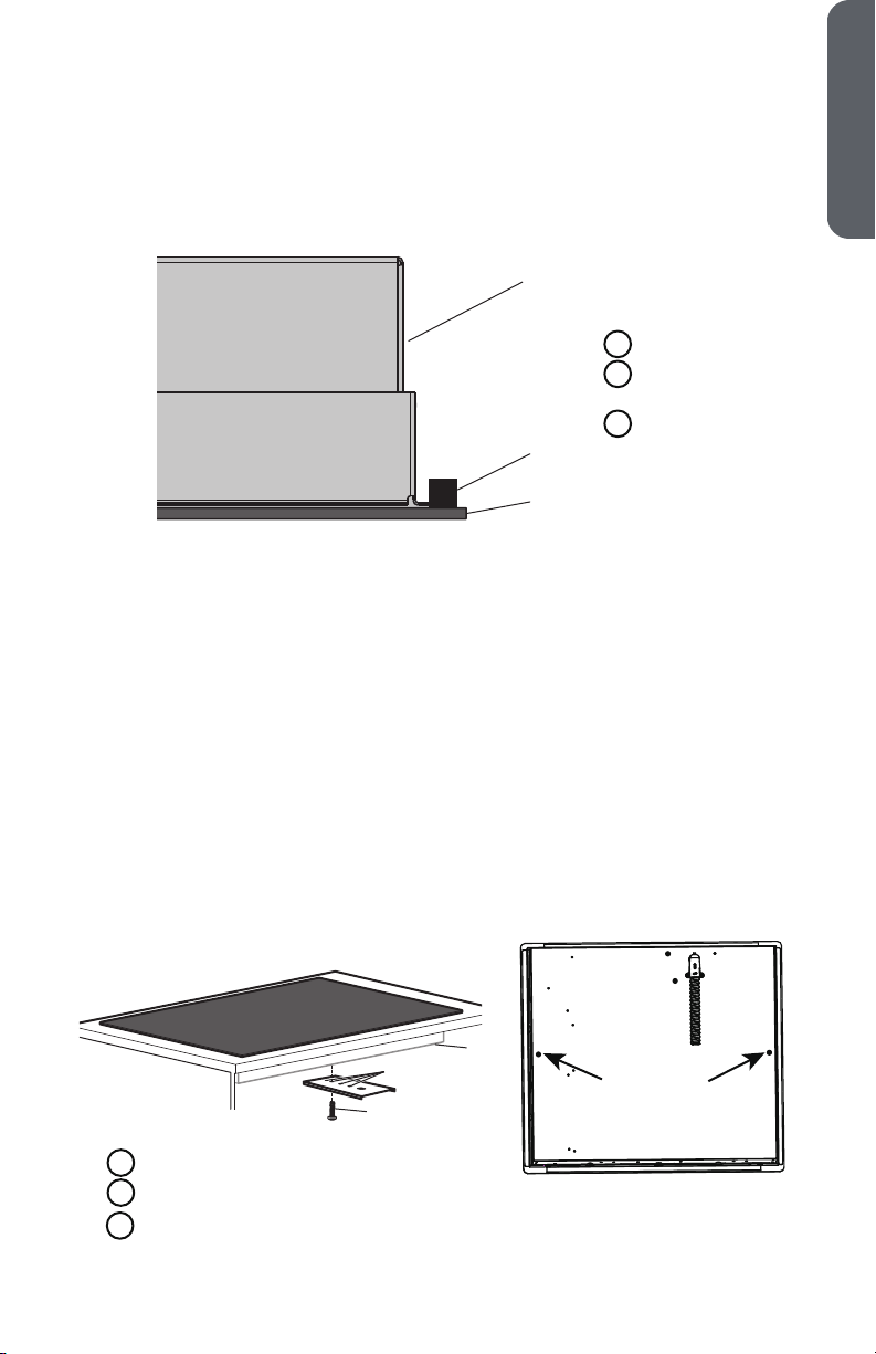
1. With the adhesive side down, apply the foam tape (provided) around the
underside of the entire cooktop. Place the foam tape so that it is approximately
¹⁄₁₆" (0.16 cm) in from the edge of the cooktop.
NOTE: The foam tape cushions the underside of the cooktop glass to help
the cooktop rest level on uneven countertops.
a
Cooktop Base
A
Foam Tape
B
(provided)
Cooktop
C
b
c
2. Turn the cooktop right side up and insert the cooktop base into the cutout
opening.
NOTE:
Make sure the cooktop is centered within the opening and that the
•
front edge of the cooktop is parallel with the front edge of the
countertop.
If you need to reposition the cooktop, lift the entire cooktop from the
•
opening to avoid scratching the countertop.
3. Working from underneath the cooktop base, remove the clamping bracket
attachment screws (one on each side) from the bottom of the cooktop base.
4. Determine which mounting holes in the clamping brackets will allow the bracket
to extend out far enough from the cooktop base to accommodate the
installation of clamping screws.
5. Using the bracket attachment screws removed earlier, insert a screw through
the selected bracket mounting hole, and fasten the clamping bracket to the
cooktop base. Repeat for the other side of the cooktop, and then completely
tighten both attachment screws.
ENGLISH
Cooktop Base
A
Bracket Mounting Hole
B
Bracket Attachment Screw
C
a
b
7
b
a
c
d
e f
WARNING
Electrical Shock Hazard
Disconnect power before servicing.
Use 8 gauge copper wire.
Electrically ground cooktop.
Failure to do so can result in death, fire or electrical shock.
ENGLISH
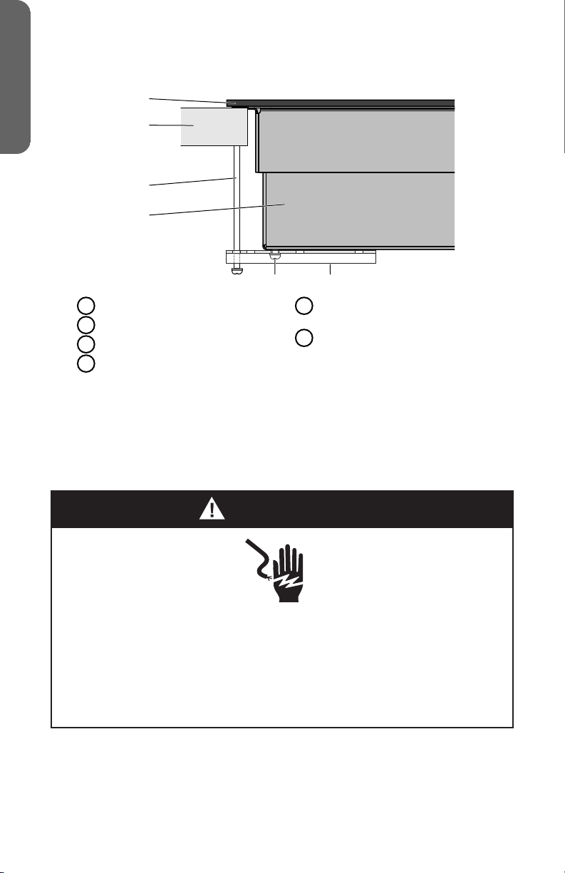
6. Insert the long clamping screw (provided) into the outermost hole of the
clamping bracket. Repeat for the other side of the cooktop.
Glass Cooktop
A
Countertop
B
Clamping Screw
C
Cooktop Base
D
7. Using a screwdriver, tighten the clamping screws against the countertop. Do
not overtighten the screws.
Clamping Bracket Attachment
E
Screw
Clamping Bracket (extends from
F
the cooktop base to underneath
the countertop)
STEP 4 - MAKE DIRECT WIRE ELECTRICAL
CONNECTION
To properly install your cooktop, complete electrical connections according to local
codes and ordinances.
Be sure your appliance is properly installed and grounded by a qualied
technician. Ask your dealer to recommend a qualied technician or an authorized
repair service.
This appliance is manufactured with a green GROUND wire connected to the
cooktop chassis. After making sure that the power has been turned o, connect the
exible conduit from the cooktop to the junction box using a UL listed conduit
connector.
8
The Grounded Neutral and Ungrounded Neutral Graphics on the following pages and
WARNING
Electrical Shock Hazard
Grounding through the neutral conductor is prohibited for new
branch-circuit installations (1996 NEC); mobile homes; and recreational
vehicles, or in an area where local codes prohibit grounding through the
neutral conductor. For installations where grounding through the
neutral conductor is prohibited, see the Ungrounded Neutral graphic.
Use grounding terminal or lead to ground unit.
Connect neutral terminal or lead to branch circuit neutral in usual
manner.
Failure to do so could result in death, fire or electric shock.
the instructions provided, present the most common way of connecting the
cooktop. Your local codes and ordinances, of course, take precedence over these
instructions.
3-WIRE CONNECTION (GROUNDED NEUTRAL) - U.S.A. ONLY
ENGLISH
3-Wire Cable from Home Power Supply
IMPORTANT: Use the 3-wire cable from home power supply where local
codes permit a 3-wire connection.
1. Disconnect power.
9
a
b
c
d
g
h
f
e
i
ENGLISH
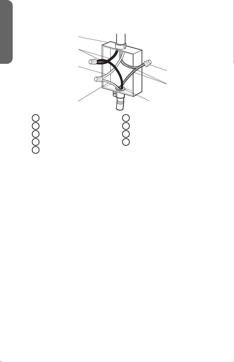
Grounded Neutral
Junction Box (not provided)
A
Black Wires
B
Neutral (White) Wire
C
Ground (Green or Bare) Wire
D
Cable from Cooktop
E
2. Attach the UL listed conduit connector (F) to the junction box (not provided).
3. Thread the cable from the cooktop (E) through the conduit connector to access
the wires, and then tighten the conduit connector screw.
4. Connect the 2 black wires (B) together using a UL listed wire connector.
5. Connect the neutral (white) wire (C) from the house electrical supply to the
ground (green or bare) wire (D) from the cooktop cable using a UL listed wire
connector.
6. Connect the 2 red wires (G) together using a UL listed wire connector (H).
7. Gently tuck the wire connections into the junction box, and install the junction
box cover.
UL Listed Conduit Connector
F
Red Wires
G
UL Listed Wire Connector
H
House Electrical Supply
I
4-WIRE CONNECTION (UNGROUNDED NEUTRAL) - U.S.A. ONLY
4-Wire Cable from Home Power Supply
IMPORTANT: Use the 4-wire cable from home power supply in the U.S. where
local codes do not allow grounding through neutral, new branch circuit
installations (1996 NEC), mobile homes and recreational vehicles, new
construction and in Canada.
1. Disconnect power.
10

Ungrounded Neutral
i
b
c
d
g
f
e
h
a
ENGLISH
Junction Box (not provided)
A
Black Wires
B
Red Wires
C
Cable from Cooktop
D
UL Listed or CSA Approved
E
Conduit Connector
2. Attach the UL listed conduit connector (E), to the junction box (not provided).
3. Thread the cable from the cooktop (D) through the conduit connector to
access the wires, and then tighten the conduit connector screw.
4. Connect the 2 black wires (B) together using a UL listed wire connector.
5. Connect the 2 red wires (C) together using a UL listed wire connector.
6. Connect the 2 ground (green or bare) wires (F) together using a UL listed wire
connector (G).
7. Attach a UL listed wire connector to the neutral (white) wire (H) from the house
electrical supply.
8. Gently tuck the wire connections into the junction box, and install the junction
box cover.
Ground (Green or Bare) Wire
F
UL Listed Wire Connector
G
Neutral (White) Wire
H
House Electrical Supply
I
STEP 5 - COMPLETE INSTALLATION
1. Clean cooktop before use with a solution of mild detergent and warm water.
Dry thoroughly with a soft cloth. For more information, see “Cooktop Care” in
the User Manual.
2. Reconnect power at the circuit breaker or fuse box.
3. Turn on each element to check that it is heating correctly.
4. Check that the indicator lights on the control panel, and the interior oven lights
illuminate correctly.
If the cooktop does not operate correctly, check the following:
Household fuse is intact and tight; or circuit breaker has not tripped.
•
Cooktop is plugged into a grounded outlet.
•
Electrical supply is connected.
•
Contact a
qualied electrician to verify the electrical supply.
11

TABLE DES MATIÈRES
SÉCURITÉ DE LA TABLE DE CUISSON ..................................................... 13
EXIGENCES D'INSTALLATION ............................................................... 13
Outils et pièces ........................................................................... 13
Exigences d’emplacement ............................................................. 14
Spécications électriques .............................................................. 17
INSTRUCTIONS D'INSTALLATION .......................................................... 18
Étape 1 - Déballage de la table de cuisson .......................................... 18
Étape 2 - Préparation pour installation .............................................. 18
Étape 3 - Installation de la table de cuisson ......................................... 19
Étape 4 - Raccordement électrique direct .......................................... 20
Étape 5 - Fin de l’installation ........................................................... 24
FRANÇAIS
12
 Loading...