

Page 1

Haier
Haier
Haier
Haier
SERVICE
SERVICE
SERVICE
SERVICE MANUAL
MANUAL
MANUAL
MANUAL
L
E
D
L
E
D
L
L E
E D
D TV
TV
TV
TV
Model
Model
Model
Model No.
No.
No.
No. 75UF5550
MSD3458
MSD3458
MSD3458
MSD3458
75UF5550
75UF5550
75UF5550
Chassis
Chassis
Chassis
Chassis
WARNING
WARNING
WARNING
WARNING
This service information is designed for experienced repair technicians only and is not designed for use by the general public.
It does not contain warnings or cautions to advise non-technical individuals of potential dangers in attempting to service a product.
Products powered by electricity should be serviced or repaired only by experienced professional technicians. Any attempt to service or repair
the product or products dealt with in this service information by anyone else could result in serious injury or death.
© 201 3 Qingdao Haier Electronics Co., Ltd.
All rights reserved. Unauthorized copying and distribution is a violation of law.
Page 2

CONTENTS
CONTENTS
CONTENTS
CONTENTS
Service Manual
Model
Model
Model
Model No.:
75UF5550
No.:
75UF5550
No.:
No.: 75UF5550
75UF5550
Chapter
Chapter
Chapter
Chapter 1.
1-1.
Document
1-1.
Document
1-1.
1-1. Document
Document Information
1-2.
General
1-2.
General
1-2.
1-2. General
General Guidelines...................................................................
1-3.
Important
1-3.
Important
1-3.
1-3. Important
Important Notice.......................................................................
1-3-1. Follow the regulations and warnings ..................................................... 3
1-3-2. Be careful to the electrical shock ........................................................... . 3
1-3-3. Electro static discharge (ESD)............................................................... . 3
1-3-4. About lead free solder (PbF).................................................................. . 4
1-3-5. Use the genewing parts (speci ed parts) .............................................. 4
1-3-6 Safety check after repairment................................................................. 4
1-3-7. Ordering Spare Parts............................................................................. 6
1-3-8. Photo used in this manual .....................................................................6
1-4.
How
1-4.
How
1-4.
1-4. How
How to
Using icons .............................................................................................................. . 6
Chapter
Chapter
Chapter
Chapter 2.
2-1.
Speci
2-1.
Speci
2-1.
2-1. Speci
Speci
2-2.
External
2-2.
External
2-2.
2-2. External
External pictures
1.
General
1.
General
1. General
General Information
Information
Information
Information ............................................................
Guidelines...................................................................
Guidelines...................................................................
Guidelines................................................................... ..
Notice.......................................................................
Notice.......................................................................
Notice....................................................................... ..
to
Read
to
Read
to Read
Read this
2.
2.
2. Speci
cation
cation
cation
cation list.......................................................................
this
this
this Service
Speci
Speci
Speci
list.......................................................................
list.......................................................................
list....................................................................... ..
pictures
pictures
pictures (four
Information
Information
Information
............................................................
............................................................
............................................................ ..
Service
Service
Service Manual
cation
cation
cation
cation
(four
(four
(four faces).................................................
Manual
Manual
Manual ...........................................
faces).................................................
faces).................................................
faces)................................................. ...
...........................................
...........................................
........................................... .
..
3
..
3
.. 3
3
..
3
..
3
.. 3
3
..
3
..
3
.. 3
3
.
6
.
6
. 6
6
..
8
..
8
.. 8
8
...
9
...
9
... 9
9
Chapter
Chapter
Chapter
Chapter 3.
3-1.
75UF5550
3-1.
75UF5550
3-1.
3-1. 75UF5550
75UF5550 .................................................................................11
3-1-1. Remove the Stand.......................................................... ................ ..... .. 11
3-1-2. Remove the Back Cabinet ................................................. .................. .11
3-1-3. Remove the Mainboard....................................................... .................. 11
3-1-4. Remove the Power Supply Module ................................... ................... 11
3-1-5. Remove the Speaker........................................................... .................. 11
3-1-6. Remove the Remote Control Board .................................. ................... 12
3-1- 7 . Remove the Key Board....................................................... .................. 12
Chapter
Chapter
Chapter
Chapter 4.
4-1.
Board
4-1.
Board
4-1.
4-1. Board
Board Location
4-2.
Mainboard
4-2.
Mainboard
4-2.
4-2. Mainboard
Mainboard ...............................................................................
4-2-1. Function Description .............................. ................... ............................14
4-2-2. Connector de nition ........................................... ................... ................14
4-3.
Power
4-3.
Power
4-3.
4-3. Power
Power Supply
3.
Disassemble
3.
Disassemble
3. Disassemble
Disassemble and
.................................................................................11
.................................................................................11
.................................................................................11
4.
Location
4.
Location
4. Location
Location of
Location
Location
Location .......................................................................
...............................................................................
...............................................................................
............................................................................... ..
Supply
Supply
Supply Module
.......................................................................
.......................................................................
....................................................................... ..
Module
Module
Module ............................................................
of
of
of Controls
............................................................
............................................................
............................................................ ..
and
and
and Assemble
Controls
Controls
Controls and
Assemble
Assemble
Assemble
and
and
and Components
Components
Components
Components
..
13
..
13
.. 13
13
..
14
..
14
.. 14
14
..
15
..
15
.. 15
15
4-3-1. Function Description ........................................................ ................... ..15
1
1
1
1
Page 3

Service Manual
Model
Model
Model
Model No.:
No.:
75UF5550
No.:
75UF5550
No.: 75UF5550
75UF5550
4-3-2. Connector de nition .................................................... .................. ....... . 15
4-4.
LCD
4-4.
LCD
4-4.
4-4. LCD
LCD Panel
Panel
Panel
Panel ...............................................................................
...............................................................................
...............................................................................
............................................................................... ...
...
...
... 16
16
16
16
Chapter
Chapter
Chapter
Chapter 5.
5-1.
Accessories
5-1.
Accessories
5-1.
5-1. Accessories
Accessories ............................................................................
5-2.
External
5-2.
External
5-2.
5-2. External
External Equipment
Chapter
Chapter
Chapter
Chapter 6.
6-1.
Front
6-1.
Front
6-1.
6-1. Front
Front Panel
6-2.
Back
6-2.
Back
6-2.
6-2. Back
Back Panel
6-3.
Setting
6-3.
Setting
6-3.
6-3. Setting
Setting Up
Chapter
Chapter
Chapter
Chapter 7.
7-1.
Block
7-1.
Block
7-1.
7-1. Block
Block Diagram
7-2.
Circuit
7-2.
Circuit
7-2.
7-2. Circuit
Circuit Diagram.......................................................................
Chapter
Chapter
Chapter
Chapter 8.
8-1.
Service
8-1.
Service
8-1.
8-1. Service
Service Mode
8-1-1.How to enter into Service Mode............................................................ 31
8-1-2.How to exit ............................................................................................ 31
8-2.
Measurements
8-2.
Measurements
8-2.
8-2. Measurements
Measurements and
8-2-1. The Main Menu .................................................................................... 31
8-2-2. General Setting .............................................................................. .. .... 32
8-2-3. Picture ................................................................................. ........ ......... 32
8-2-4. Sound ............................................................... ................................ .... 33
8-2-5. Debug ................................................................................... ............. ... 33
8-3.
Software
8-3.
Software
8-3.
8-3. Software
Software Update
8-3-1. T.VST59 software update .................................................................... 34
5.
Installation
5.
Installation
5. Installation
Installation Instructions
............................................................................
............................................................................
............................................................................ ..
Equipment
Equipment
Equipment Connections.........................................
6.
Operation
6.
Operation
6. Operation
Operation Instructions
Panel
Panel
Panel Controls..............................................................
Panel
Panel
Panel Controls
7.
7.
7. Electrical
Diagram
Diagram
Diagram .
Diagram.......................................................................
Diagram.......................................................................
Diagram....................................................................... ...30
8.
8.
8. Measurements
Controls..............................................................
Controls..............................................................
Controls.............................................................. ...
Controls
Controls
Controls ..............................................................
Up
Your
Up
Your
Up Your
Your Remote
Electrical
Electrical
Electrical Parts
Measurements
Measurements
Measurements and
Mode
Mode
Mode ..........................................................................
Update
Update
Update .....................................................................
Remote
Remote
Remote Control
.
.......................................................................
.
.......................................................................
. .......................................................................
....................................................................... ....
..........................................................................
..........................................................................
.......................................................................... ..31
and
Adjustments
and
Adjustments
and Adjustments
Adjustments ..........................................
.....................................................................
.....................................................................
..................................................................... .34
Instructions
Instructions
Instructions
Connections.........................................
Connections.........................................
Connections......................................... ...
Instructions
Instructions
Instructions
..............................................................
..............................................................
.............................................................. ...
Control
Control
Control .........................................
Parts
Parts
Parts
.........................................
.........................................
......................................... ....
and
and
and Adjustments
Adjustments
Adjustments
Adjustments
..........................................
..........................................
.......................................... ..31
..
..
.. 18
...
...
... 19
...
...
... 20
...
...
... 21
....
....
.... 22
....
....
.... 23
...30
...30
...30
..31
..31
..31
..31
..31
..31
.34
.34
.34
18
18
18
19
19
19
20
20
20
21
21
21
22
22
22
23
23
23
Chapter
Chapter
Chapter
Chapter 9.
9-1.
Simple
9-1.
Simple
9-1.
9-1. Simple
Simple check
9-2.
Mainboard
9-2.
Mainboard
9-2.
9-2. Mainboard
Mainboard IC
9-3.
Mainboard
9-3.
Mainboard
9-3.
9-3. Mainboard
Mainboard Failure
9-4.
Pannel
9-4.
Pannel
9-4.
9-4. Pannel
Pannel Failure.........................................................................
2
2
2
2
9.
Trouble
9.
Trouble
9. Trouble
Trouble shooting
check
check
check ..........................................................................
Failure.........................................................................
Failure.........................................................................
Failure......................................................................... .45
..........................................................................
..........................................................................
.......................................................................... .35
IC
Introduction.....................................................
IC
Introduction.....................................................
IC Introduction.....................................................
Introduction..................................................... .38
Failure
Failure
Failure Check.......................................................
shooting
shooting
shooting
Check.......................................................
Check.......................................................
Check....................................................... .39
.35
.35
.35
.38
.38
.38
.39
.39
.39
.45
.45
.45
Page 4

Service Manual
Model
Model
Model
Model No.:
No.:
75UF5550
No.:
75UF5550
No.: 75UF5550
75UF5550
Chapter
Chapter
Chapter
Chapter 1.
1-1.
Document
1-1.
Document
1-1.
1-1. Document
Document Information
Document format: Adobe PDF
Author: Gao Bingbing
Compiler:
1-2.
General
1-2.
General
1-2.
1-2. General
General Guidelines
When servicing, observe the original lead dress. If a short circuit is found, replace all parts which
have been overheated or damaged by the short circuit.
After servicing, see to it that all the protective devices such as insulation barriers, insulation papers
shields are properly installed.
After servicing, make the following leakage current checks to prevent the customer from being
exposed to shock hazards.
1) Leakage Current Cold Check
2) Leakage Current Hot Check
3) Prevention of Electro Static Discharge (ESD) to Electrostatically Sensitive
1.
General
1.
General
1. General
General Information
Information
Information
Information
Guidelines
Guidelines
Guidelines
Information
Information
Information
1-3.
Important
1-3.
Important
1-3.
1-3. Important
Important Notice
1-3-1. Follow the regulations and warnings
Most important thing is to list up the potential hazard or risk for the service personnel to open
the units and disassemble the units. For example, we need to describe properly how to avoid the
possibility to get electrical shock from the live power supply or charged electrical parts (even the
power is off).
1-3-2. Be careful to the electrical shock
To prevent damage which might result in electric shock or re, do not expose this TV set to rain
or excessive moisture. This TV must not be exposed to dripping or splashing water, and objects
lled with liquid, such as vases, must not be placed on top of or above the TV.
Notice
Notice
Notice
This symbol indicates that high voltage is present inside.It is dangerous to make any
king of contact with any inside part of this product.
This symbol indicates that there are important operating and maintenance instructions
in the literture accompanying the appliance.
1-3-3. Electro static discharge (ESD)
Some semiconductor (solid state) devices can be damaged easily by static electricity. Such
3
3
3
3
Page 5

Service Manual
Model
Model
Model
Model No.:
No.:
75UF5550
No.:
75UF5550
No.: 75UF5550
75UF5550
components commonly are called Electrostatically Sensitive (ES) Devices. The following
techniques should be used to help reduce the incidence of component damage caused by
electros static discharge (ESD).
Electrostatically
Electrostatically
Electrostatically
Electrostatically Sensitive
Some semiconductor (solid-state) devices can be damaged easily by static electricity. Such
components commonly are called Electrostatically Sensitive (ES) Devices. Examples of typical
ES devices are integrated circuits and some field-effect transistors and semiconductor "chip"
components. The following techniques should be used to help reduce the ncidence of component
damage caused by static by static electricity.
1. Immediately before handling any semiconductor component or semiconductor-equipped
assembly, drain off any electrostatic charge on your body by touching a known earth ground.
Alternatively, obtain and wear a commercially available discharging wrist strap device, which
should be removed to prevent potential shock reasons prior to applying power to the unit under
test.
2. After removing an electrical assembly equipped with ES devices, place the assembly on a
conductive surface such as aluminum foil, to prevent electrostatic charge buildup or exposure of
the assembly.
Sensitive
Sensitive
Sensitive (ES)
(ES)
(ES)
(ES) Devices
Devices
Devices
Devices
1-3-4. About lead free solder (PbF)
This product is manufactured using lead-free solder as a part of a movement within the
consumer products industry at large to be environmentally responsible. Lead-free solder must be
used in the servicing and repairing of this product.
1-3-5. Use the genewing parts (speci ed parts)
Special parts which have purposes of re retardant (resistors), high-quality sound (capacitors),
low noise (resistors), etc. are used.
When replacing any of components, be sure to use only manufacture's speci ed parts shown in
the parts list.
Safety
Safety
Safety
Safety Component
● Components identi ed by mark have special characteristics important for safety.
Component
Component
Component
1-3-6 Safety check after repairment
Con rm that the screws, parts and wiring which were removed in order to service are put in the
original positions, or whether there are the positions which are deteriorated around the serviced
places serviced or not. Check the insulation between the antenna terminal or external metal and
the AC cord plug blades. And be sure the safety of that.
General
General
General
General Servicing
Servicing
Servicing
Servicing Precautions
Precautions
Precautions
Precautions
4
4
4
4
Page 6

Service Manual
Model
Model
Model
Model No.:
1. Always unplug the receiver AC power cord from the AC power source before:
a. Removing or reinstalling any component, circuit board module or any other receiver
assembly.
b. Disconnecting or reconnecting any receiver electrical plug or other electrical connection.
c. Connecting a test substitute in parallel with an electrolytic capacitor in the receiver.
CAUTION:
CAUTION:
CAUTION:
CAUTION:
may result in an explosion hazard.
2. Test high voltage only by measuring it with an appropriate high voltage meter or other voltage
measuring device (DVM, FETVOM, etc) equipped with a suitable high voltage probe.
Do not test high voltage by "drawing an arc".
3. Do not spray chemicals on or near this receiver or any of its assemblies.
4. Unless specified otherwise in this service manual, clean electrical contacts only by applying
the following mixture to the contacts with a pipe cleaner, cotton-tipped stick or comparable nonabrasive applicator; 10% (by volume) Acetone and 90% (by volume) isopropyl alcohol (90%-99%
strength).
A wrong part substitution or incorrect polarity installation of electrolytic capacitors
No.:
75UF5550
No.:
75UF5550
No.: 75UF5550
75UF5550
CAUTION:
CAUTION:
CAUTION:
CAUTION:
Unless speci ed otherwise in this service manual, lubrication of contacts is not required.
Capacitors may result in an explosion hazard.
5. Do not defeat any plug/socket B+ voltage interlocks with which receivers covered by this
service manual might be equipped.
6. Do not apply AC power to this instrument and/or any of its electrical assemblies unless all
solid-state device heat sinks are correctly installed.
7. Always connect the test receiver ground lead to the receiver chassis ground before connecting
the test receiver positive lead.
Always remove the test receiver ground lead last. Capacitors may result in an explosion
hazard.
8. Use with this receiver only the test xtures speci ed in this service manual.
CAUTION:
CAUTION:
CAUTION:
CAUTION: Do not connect the test xture ground strap to any heat sink in this receiver.
9. Remove the antenna terminal on TV and turn on the TV.
This is a ammable mixture.
10. Insulation resistance between the cord plug terminals and the eternal exposure metal should
be more than Mohm by using the 500V insulation resistance meter.
11. If the insulation resistance is less than M ohm, the inspection repair should be required.
If you have not the 500V insulation resistance meter, use a Tester. External exposure metal:
Antenna terminal Headphone jack.
5
5
5
5
Page 7

Service Manual
Model
Model
Model
Model No.:
No.:
75UF5550
No.:
75UF5550
No.: 75UF5550
75UF5550
12. Use only a grounded-tip soldering iron to solder or unsolder ES devices.
13. Use only an anti-static type solder removal device. Some solder removal devices not
classi ed as "anti-static" can generate electrical charges suf cient to damage ES devices.
14. Do not use freon-propelled chemicals. These can generate electrical charges sufficient to
damage ES devices.
15. Do not remove a replacement ES device from its protective package until immediately
before you are ready to install it.
(Most replacement ES devices are packaged with leads electrically shorted together by
conductive foam, aluminum foil or comparable conductive material).
16. Immediately before removing the protective material from the leads of a replacement ES
device, touch the protective material to the chassis or circuit assembly into which the device will
be installed.
CAUTION:
CAUTION:
CAUTION:
CAUTION:
precautions.
17. Minimize bodily motions when handling unpackaged replacement ES devices. (Otherwise
harmless motion such as the brushing together of your clothes fabric or the lifting of your foot
from a carpeted oor can generate static electricity suf cient to damage an ES device.)
Be sure no power is applied to the chassis or circuit, and observe all other safety
1-3-7. Ordering Spare Parts
Please include the following informations when you order parts. (Particularly the Version letter)
1. Model number, serial number and software version
The model number and serial number can be found on the back cover of each product. Software
version can be found in the Spare Parts List.
2. Spare part No. and description
Spare part No. and description can be found in the Spare Parts List.
1-3-8. Photo used in this manual
The illustration and photos used in this Service Manual may not base on the final design of
products, which may differ from your products in some way.
1-4.
How
1-4.
How
1-4.
1-4. How
How to
Using icons
icon is described in the table below:
6
6
6
6
to
Read
to
Read
to Read
Read this
Icons are used to attract the attention of the reader to speci c information. The meaning of each
Note:
A “ note ” provides information that is not indispensable, but may nevertheless be
valuable to the reader, such as tips and tricks.
this
Service
this
Service
this Service
Service Manual
Manual
Manual
Manual
Page 8

Caution:
Caution:
Caution:
Caution:
Service Manual
Model
Model
Model
Model No.:
A “ caution ” is used when there is danger that the reader, through incorrect
manipulation, may damage equipment, loose data, get an unexpected result or has to
restart(part of) a procedure.
Warning:
Warning:
Warning:
Warning:
A “ warning ” is used when there is danger of personal injury.
Reference:
Reference:
Reference:
Reference:
A “ reference ” guides the reader to other places in this binder or in this manual, where
he/she will nd additional information on a speci c topic.
No.:
75UF5550
No.:
75UF5550
No.: 75UF5550
75UF5550
7
7
7
7
Page 9

Service Manual
Model
Model
Model
Model No.:
No.:
75UF5550
No.:
75UF5550
No.: 75UF5550
75UF5550
Chapter
Chapter
Chapter
Chapter 2.
2-1.
Speci
2-1.
Speci
2-1.
2-1. Speci
Speci
cation
Model
Model
Model
Model 75UF5550
Screen Size 75 "
Aspect Ratio 16:9
Resolution 3840 x 2160
Brightness (cd/m ² ) 300
Contrast 35 00:1
Response Time (ms) 6.5
Angel of View H:1 70 ° , V:1 70 °
Color Display 1.07G
OSD Language
Color System PAL/SECAM
2.
Speci
2.
Speci
2. Speci
Speci
cation
cation
cation list
list
list
list
cation
cation
cation
cation
English , Arabic, farsi ,French
, Portuguese ,Russian .
Audio System BG/DK/L/I
Audio Output Power (Built-in) (W) 10 W × 2
Audio Output Power (outer) (W) No
Total Power Input (W) 350 W
Voltage Range (V) AC1 0 0V~240V
Power Frequency (Hz) 50~60Hz
Time of Sleep Timer (MINS) 240Min
Net Weight (KG) 30.3
Gross Weight (KG) 31.3
Net Dimension (MM) 1685x973x84mm
Packaged Dimension (MM) 1923x322x1210mm
,French, .
8
8
8
8
Page 10

2-2.
External
2-2.
External
2-2.
2-2. External
External pictures
pictures
pictures
pictures (four
(four
(four
(four faces)
faces)
faces)
faces)
Service Manual
Model
Model
Model
Model No.:
No.:
75UF5550
No.:
75UF5550
No.: 75UF5550
75UF5550
Front
Front
Front
Front Side
Side
Side
Side
Up
Side
Up
Side
Up
Up Side
Side
9
9
9
9
Page 11

Service Manual
Model
Model
Model
Model No.:
No.:
75UF5550
No.:
75UF5550
No.: 75UF5550
75UF5550
Right
Right
Right
Right Side
Side
Side
Side
Back
Back
Back
Back Side
10
10
10
10
Side
Side
Side
Page 12

Service Manual
Model
Model
Model
Model No.:
No.:
75UF5550
No.:
75UF5550
No.: 75UF5550
75UF5550
Chapter
Chapter
Chapter
Chapter 3.
3-1.
75UF5550
3-1.
75UF5550
3-1.
3-1. 75UF5550
75UF5550
3-1-1. Remove the Stand 3-1-3. Remove the Mainboard and 6M60 Board
1. Lay down the TV set .
2. Remove the four screws from the stand which
in the picture above.
3. Remove the stand.
3.
Disassemble
3.
Disassemble
3. Disassemble
Disassemble and
and
and
and Assemble
Assemble
Assemble
Assemble
1. Remove the eight screws .
2. Remove the Mainbord and 6M60 Board.
3-1-4. Remove the Power Supply Module
3-1-2. Remove the Back Cabinet
1.Remove the thirteen screws .
2. Flip machine, panel side up.
3.Carefully raise the Front shell from
bottom.
1. Remove the four screws.
2. Remove the Power Supply Module.
3-1-5. Remove the Speaker
Remove the Speaker indicated by red circle in
below picture.
11
11
11
11
Page 13

Service Manual
Model
Model
Model
Model No.:
3-1-6. Remove the Remote Control Board And the Key Board
No.:
75UF5550
No.:
75UF5550
No.: 75UF5550
75UF5550
Remove the Remote Control Board and the Key Board indicated by
red circle in below picture.
12
12
12
12
Page 14

Service Manual
Model
Model
Model
Model No.:
No.:
75UF5550
No.:
75UF5550
No.: 75UF5550
75UF5550
Chapter
Chapter
Chapter
Chapter 4.
4-1.
Board
4-1.
Board
4-1.
4-1. Board
Board Location
A Power Board
4.
Location
4.
Location
4. Location
Location of
Location
Location
Location
of
Controls
of
Controls
of Controls
Controls and
and
and
and Components
Components
Components
Components
C 6M60 Board
B Main Board
D Panel
No.
No.
No.
No. Parts
A Board HKL-750203 Power board
B Board T.MS3458.U801 Main board
C Board PL.MS6M60.1 6M60 board
D Panel SAMSUNG LSC750FF01 LED Panel
Parts
Type
Parts
Parts Type
Type
Type Description
Description
Description
Description
13
13
13
13
Page 15
Service Manual
Model
Model
Model
Model No.:
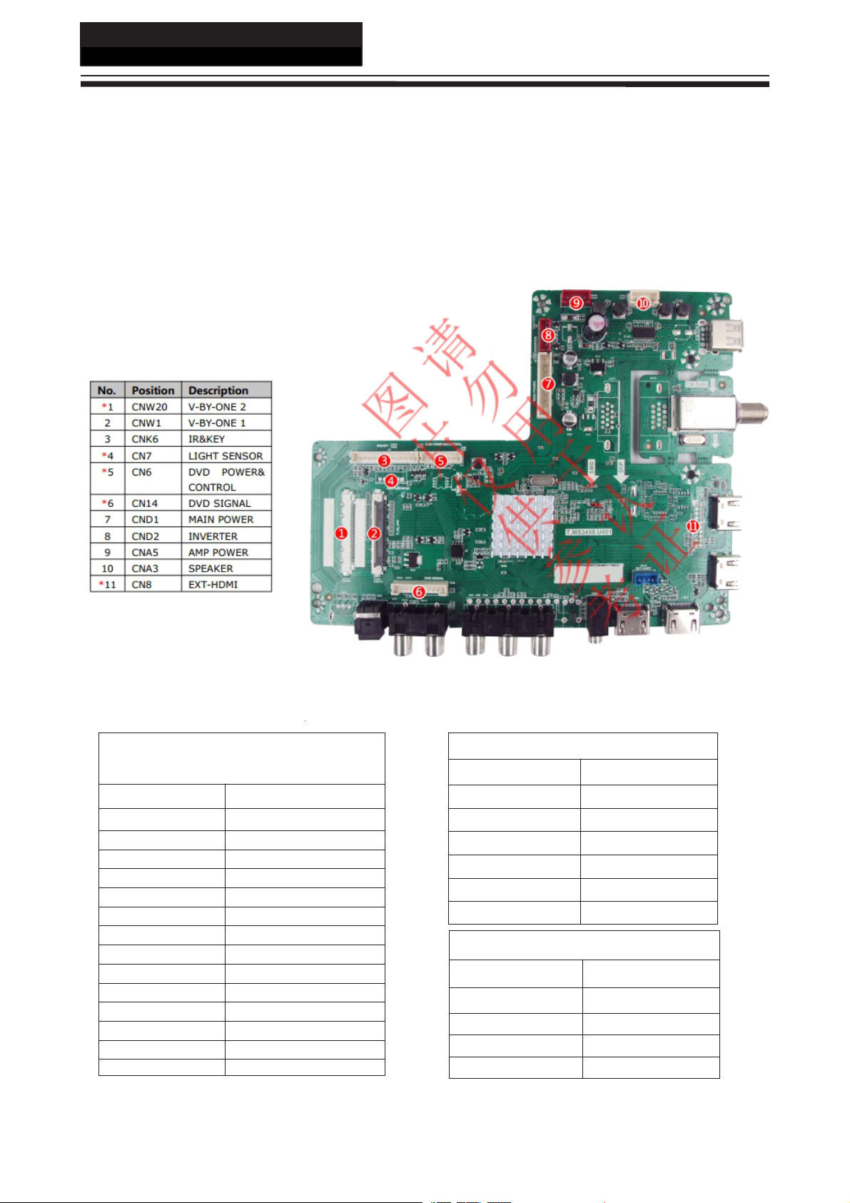
4-2.
4-2.
4-2.
4-2. Mainboard
No.:
75UF5550
No.:
75UF5550
No.: 75UF5550
75UF5550
Mainboard
Mainboard
Mainboard
4-2-1.
4-2-1.
4-2-1.
4-2-1. Function
4-2-2.
4-2-2.
4-2-2.
4-2-2. Connector
Function
Function
Function Description
Process signal which incept from exterior equipment then translate into signal that panel can
display.
Connector
Connector
Connector de
Description
Description
Description
de
nition
de
nition
de
nition
nition
14
14
14
14
IR
&
Key
IR
&
Key
IR
IR &
& Key
Key Interface
Pin
number
Pin
number
Pin
Pin number
number Signal
1
2 RED
3 GRE
4 IR
5 GND
6 K0
7 K1
8 K2
9 K3
10 K4
11 K5
12 K6
13 K7
14 GND
Interface
Interface
Interface
CND1
CND1
CND1
CND1
Signal
Signal
Signal name
5V
name
name
name
Inverter
Inverter
Inverter
Inverter connector
Pin
number
Pin
number
Pin
Pin number
number Signal
1
2
3
4
5
6
Speaker
Speaker
Speaker
Speaker connector
Pin
number
Pin
number
Pin
Pin number
number Signal
1
2 ROUT-
3 LOUT-
4 LOUT+
connector
connector
connector CND2
connector
connector
connector CNA3
Signal
Signal
Signal name
12V
12V
BLO
ADJ
GND
GND
Signal
Signal
Signal name
ROUT+
CND2
CND2
CND2
name
name
name
CNA3
CNA3
CNA3
name
name
name
Page 16

4-3.
Power
4-3.
Power
4-3.
4-3. Power
Power Supply
4-3-1.
4-3-1.
4-3-1.
4-3-1. Function
Function
Function
Function Description
To
supply power for Mainboard, Panel.
Supply
Supply
Supply Module
Module
Module
Module
Description
Description
Description
Service Manual
Model
Model
Model
Model No.:
No.:
75UF5550
No.:
75UF5550
No.: 75UF5550
75UF5550
4-3-2.
4-3-2.
4-3-2.
4-3-2. Connector
Connector
Connector
Connector de
Mainboard
Mainboard
Mainboard
Mainboard power
Pin
Pin
Pin
Pin number
C
O
N
1
C
C
C O
is
O
N
1
is
O N
N 1
1 is
is the
connector
connector
connector
connector CON3
number
number
number Signal
1 12V
2 12 V
3 GND
4 GND
5 5V
6 5V
7 GND
8 GND
9 STB
10 5VSB
the
Power
the
Power
the Power
Power cord
de
nition
de
nition
de
nition
nition
CON1
CON1
CON1
CON1 CON3
power
power
power supply
supply
supply
supply
CON3
CON3
CON3
Signal
Signal
Signal name
cord
cord
cord connector
name
name
name
connector
connector
connector .
.
.
.
CON3
CON3
CON3
LED
LED
LED
LED driver
Pin
number
Pin
number
Pin
Pin number
number Signal
1 +
2 -
Backlight
Backlight
Backlight
Backlight adjust
1 BL_ON
2 ADJ
3 GND
AMP
AMP
AMP
AMP power
1 GND
2 GND
3 VCC
4 VCC
CON
CON
CON
CON 5
CON
CON
CON
CON 6
CON4
CON4
CON4
CON4
CON2
CON2
CON2
CON2
driver
driver
driver connector
power
power
power connector
connector
connector
connector
C
ON5/6
C
ON5/6
C
C ON5/6
ON5/6
Signal
Signal
Signal name
adjust
adjust
adjust connector
C
C
C
C ON2
connector
connector
connector C
ON2
ON2
ON2
connector
connector
connector
6
6
6
5
5
5
C
C
C O
name
name
name
O
O
O N4
N4
N4
N4
15
15
15
15
Page 17

Service Manual
Model
Model
Model
Model No.:
4-4.
4-4.
4-4.
4-4. LCD
No.:
75UF5550
No.:
75UF5550
No.: 75UF5550
75UF5550
LCD
LCD
LCD Panel
Panel
Panel
Panel
75UF5550
75UF5550
75UF5550
75UF5550
Backlight
Backlight
Backlight
Backlight Unit
Unit
Unit
Unit
LVDS
LVDS
LVDS
LVDS CONNECTOR
CONNECTOR
CONNECTOR
CONNECTOR CN1
CN1
CN1
CN1
16
16
16
16
Page 18

Service Manual
Model
Model
Model
Model No.:
No.:
75UF5550
No.:
75UF5550
No.: 75UF5550
75UF5550
17
17
17
17
Page 19

Service Manual
Model
Model
Model
Model No.:
No.:
75UF5550
No.:
75UF5550
No.: 75UF5550
75UF5550
Chapter
Chapter
Chapter
Chapter 5.
5-1.
Accessories
5-1.
Accessories
5-1.
5-1. Accessories
Accessories
5.
5.
5. Installation
Installation
Installation
Installation Instructions
Instructions
Instructions
Instructions
Remote Control
Batteries
18
18
18
18
Page 20

5-2.
External
5-2.
External
5-2.
5-2. External
External Equipment
Equipment
Equipment
Equipment Connections
Connections
Connections
Connections
Service Manual
Model
Model
Model
Model No.:
No.:
75UF5550
No.:
75UF5550
No.: 75UF5550
75UF5550
Antenna
Antenna
Antenna
Antenna Connection
Connect your aerial to the back of the TV into the
ANTENNA IN socket.
Improve
Improve
Improve
Improve Your
To improve picture quality in a poor signal area, use a
signal ampli er (not supplied).
Connect
Connect
Connect
Connect Your
You can use your TV as a monitor for your personal
computer by connecting it with a VGA cable (not
supplied).
Read your computer user guide and check it has a
A
VGA connector.
Turn off your TV and PC.
B
Connect a D type 15-pin VGA interface cable to the
C
VGA video interface connector on the PC. Connect
the other end of the cable to the PC interface
connector on the TV. Tighten the screws on the
VGA connectors and connect the audio cable (not
supplied) to the audio input socket on the back of the
TV.
Turn on the TV rstly and then the PC.
D
Press the Source button on the TV or TV remote
E
control to set the video input mode to PC.
Once the image shows, if there is noise present,
F
change the PC mode to other resolutions, change the
refresh rate to other rate or adjust the brightness and
contrast on the menu until the picture is clear.
Connection
Connection
Connection
Your
Your
Your Signal
Your
Your
Your PC
Signal
Signal
Signal
PC
to
PC
to
PC to
to the
the
the
the TV
TV
TV
TV
Connect
Connect
Connect
Connect a
Your
Your
Your
Your TV
There are two ways in which you can connect a DVD
player or VCR to your TV. Make sure that both the TV
and DVD player or VCR are switched off before you
connect them.
HDMI
HDMI
HDMI
HDMI Input
A
Connect the cable from the HDMI device to the TV
HDMI socket.
Press the SOURCE
B
Refer to the HDMI device user guide for how to
C
operate.
Note : The TV have no VGA.
a
DVD
a
DVD
a DVD
DVD Player
TV
TV
TV
Input
Input
Input
SOURCE
SOURCE
SOURCE button to select HDMI mode.
Player
Player
Player or
or
or
or VCR
VCR
VCR
VCR to
to
to
to
Connect
Connect
Connect
Connect a
Connect the DVD video outputs (Y, P b , P r ) to the
COMPONENT (Y, P b , P r ) IN socket on your TV.
Turn on the DVD player and insert a DVD disk.
A
Press the SOURCE button to select COMPONENT
B
mode.
Refer to the DVD player user guide for operating
C
instructions.
a
DVD
a
DVD
a DVD
DVD Player
Player
Player
Player to
to
Your
to
Your
to Your
Your TV
TV
TV
TV
19
19
19
19
Page 21

Service Manual
Model
Model
Model
Model No.:
No.:
75UF5550
No.:
75UF5550
No.: 75UF5550
75UF5550
Chapter
Chapter
Chapter
Chapter 6.
6-1.
Front
6-1.
Front
6-1.
6-1. Front
Front Panel
Panel
Panel
Panel Controls
6.
Operation
6.
Operation
6. Operation
Operation Instructions
Controls
Controls
Controls
Instructions
Instructions
Instructions
20
20
20
20
Page 22

6-2.
Back
6-2.
Back
6-2.
6-2. Back
Back Panel
Panel
Panel
Panel Controls
Controls
Controls
Controls
Service Manual
Model
Model
Model
Model No.:
No.:
75UF5550
No.:
75UF5550
No.: 75UF5550
75UF5550
21
21
21
21
Page 23

ServiceManual
Model
Model
Model
ModelNo.:
6-3.
6-3.
6-3.
6-3.Setting
Whenusingtheremotecontrol,aimittowardstheremotesensorontheTV.
No.:
75UF5550
No.:
75UF5550
No.:75UF5550
75UF5550
Setting
Setting
SettingUp
Up
Your
Up
Your
UpYour
YourRemote
Remote
Remote
RemoteControl
Control
Control
Control
12
3
45
6
89
1011
1213
1416
1517
1819
1
POWER.
1
1
1
2
INPUT.
2
2
2
3
3
3
3
4
4
4
4
5
5
5
5
6
6
6
6
7
7
7
7
8
8
8
8
9
9
9
9
10
10
10
10
11
11
11
11
12
12
12
12
13
13
13
13
14
14
14
14
15
15
15
7
15
16
16
16
16
17
17
17
17
18
18
18
18
19
19
19
19
20
20
20
20
21
21
21
21
22
22
22
22
23
23
23
23
24
24
24
24
25
25
25
25
26
26
26
26
Shortcutbutton.
USB
CC.
HOME;
ProgramNumberChannelselection.
RECALLbutton.
VOL+/VOL-:Volumeselection
CH∧/CH∨:Channelselection.
Mute.
Menubutton.
Backbutton.
Exitbutton.
DISPLAYbutton.
SAPbutton.
Sleepbutton.
Widebutton.
Audiobutton.
PictureMode.
OKbutton.
ChannelList.
Favoriteprogram.
Play/Pausebutton(onlyforUSB).
EPGbutton.
FastReverse(onlyforUSB).
FastForward(onlyforUSB).
.
20
2122
2324
2526
Chapter
Chapter
Chapter
Chapter7.
7-
1
.
Circuit
7-
1
.
Circuit
7-
7-1
1.
.Circuit
CircuitDiagram
7.
Electrical
7.
Electrical
7.Electrical
ElectricalParts
Diagram
Diagram
Diagram
Parts
Parts
Parts
22
22
22
22
Page 24

1
1
2
2
3
3
4
4
5
5
6
6
7
7
8
8
9
9
10
10
11
11
12
12
13
13
14
14
15
15
16
16
D D
C C
B B
A A
1V8_DDR
5V_M
RD15
20Kohm-0402-¡À1%-1/16W
CD16
0.1uF-0402-X5R-¡À20%-16V
EN
1
GND
2
SW
3
VIN
4
FB
5
UD3
LC3406CB5TR
CD12
0.1uF-0402-X5R-¡À20%-16V
GND
GND GND
RD9
10Kohm-0402-¡À1%-1/16W
CD15
10uF-0603-X5R-¡À20%-6.3V
CD14
NC/10uF-0603-X5R-¡À20%-6.3V
RD17
10Kohm-0402-¡À5%-1/16W
GND
CD29
NC/1uF-0402-X5R-¡À20%-6.3V
CD30
22uF-0805-X5R-¡À20%-6.3V
CD31 NC/22uF-0805-X5R-¡À20%-6.3V
RD7
12K4ohm-0402-¡À1%-1/16W
CD19
0.1uF-0402-X5R-¡À20%-16V
RD10
100Kohm-0402-¡À5%-1/16W
EN
1
GND
2
SW
3
VIN
4
FB
5
UD2
SY8089AAAC
1.15V_STB
1.15V_STB
TEST
CD9
22uF-0805-X5R-¡À20%-6.3V
CD8
0.1uF-0402-X5R-¡À20%-16V
CD22
10uF-0805-X5R-¡À20%-16V
CD18
10uF-0603-X5R-¡À20%-6.3V
GND
GND GND
使用说明
Vout=0.6*(1+RD2/RD3)=0.6*(1+12.4/13)=1.172V
LD2
SCD54TL-2R2M
RD8
13Kohm-0402-¡À1%-1/16W
5V_STB
CD10
NC/10uF-0805-X5R-¡À20%-16V
CD44
10uF-0805-X5R-¡À20%-16V
CD7
10uF-0603-X5R-¡À20%-6.3V
LD4
SLN43T-6R8M
CD33
NC/22uF-0805-X5R-¡À20%-6.3V
CD34
NC/22uF-0805-X5R-¡À20%-6.3V
QD4
LMBT3904LT1G
RD35
10Kohm-0402-¡À5%-1/16W
RD48
510ohm-0402-¡À1%-1/16W
QD5
LMBT3904LT1G
RD41
1Kohm-0402-¡À5%-1/16W
RD47
10Kohm-0402-¡À5%-1/16W
5V_M
ADJ
RD46
NC/3K3ohm-0402-¡À5%-1/16W
CD38
1uF-0402-X5R-¡À20%-6.3V
GND
GND GND GND
RD37
NC/2K2ohm-0402-¡À5%-1/16W
BL_ON
GND
QD3
LMBT3904LT1G
GND
5V_M
RD32
1Kohm-0402-¡À5%-1/16W
RD33
33ohm-0402-¡À5%-1/16W
RD34
10Kohm-0402-¡À5%-1/16W
RD36
NC/4K7ohm-0402-¡À5%-1/16W
GND
LD3
FCM1005KF-121T06(120ohm-500mA)
LD5
FCM1005KF-121T06(120ohm-500mA)
CD37
NC/1uF-0402-X5R-¡À20%-6.3V
GND
3V3_STB
BL_EN
PWM/ADJ
QD2
LMBT3904LT1G
RD5
10Kohm-0402-¡À5%-1/16W
GND
5V_STB
RD1
510ohm-0402-¡À1%-1/16W
RD6 NC/10Kohm-0402-¡À5%-1/16W
CD2
0.1uF-0402-X5R-¡À20%-16V
CD5
0.1uF-0402-X5R-¡À20%-16V
CD1
0.1uF-0402-X5R-¡À20%-16V
PW_ON
GND GNDGND
CD4
NC/10uF-0603-X5R-¡À20%-6.3V
CD3
NC/10uF-0603-X5R-¡À20%-6.3V
12V 5V_STB 5V_M
PW_ON
5V_STB
GND
12V
GND
GND
5V_M
5V_M
QD1
LMBT3906LT1G
+
ED2
100uF-16V-¡À20%-6.3¡Á5.5-105 ℃(Capxon)
1
2
3
4
6
5
7
8
9
10
CND1
10PIN-2.54-D-H-G-LD
RD2
1K5ohm-0402-¡À1%-1/16W
RD3
3K3ohm-0402-¡À5%-1/16W
POW_EN
GND
GND 1
2
3
4
6
5
CND2
6PIN-2.0-D-H-红色-G-LD
12V
BL_ON
ADJ
3V3_STB
CL1
0.1uF-0402-X5R-¡À20%-16V
5V_STB
VI3VO
2
ADJ1VO
4
UL3
LC1117CLTR33
CL3
10uF-0603-X5R-¡À20%-6.3V
GND
CL2
NC/0.1uF-0402-X5R-¡À20%-16V
1
2
3
4
6
5
7
8
9
10
CN26
NC/连接插座,connect jack,10Pin,D2.54,D,SNAP,nature,L=2.8mm,DIP,CNJST
PW_ON
5V_STB
5V_M
GND
12V
GND
5V_M
GND
Panel_VCC
Panel_VCC
Panel_VCC
Panel_VCC
BL_ON
GND
GND 1
2
3
4
6
5
CN27
NC/6PIN-2.0-D-H-G-带扣-J
ADJ
12V
12V
12V
12V Panel_VCC
RD11
NC/0ohm-1206-¡À5%-1/4W
+
ED3
100uF-16V-¡À20%-6.3¡Á5.5-105 ℃(Capxon)
CD11
1uF-0402-X5R-¡À20%-6.3V GND
PICD801
PICD1002
PICD2202
PICD801
PICD1002 PICD2202
COCD8
COCD10
COCD22
PICD802
PICD1001
PICD2201
PICD802
PICD1001
PICD2201
COUD2
PIUD204
PIUD204
PIRD1001
PIRD1001
CORD10
PIRD1002
PIRD1002
PIUD201
PIUD201
PICD1102
PICD1102
COCD11
PICD1101
PICD1101
COLD2
PILD201 PILD202
PIUD203
PIUD203
PIUD205
PIUD205
PIUD202
PIUD202
PILD202
PILD201
CORD7
PIRD701 PIRD702
PIRD702
PIRD701
PIRD802
PIRD802
COCD9
CORD8
PIRD801
PIRD801
CO1015V0STB
PI1015V0STB01
PICD902
COCD18
PICD901
PICD901
PI1015V0STB01
PICD702
PICD1802
PICD1902
PICD1802 PICD1902 PICD3302 PICD3402
COCD19
PICD1801
PICD1901
PICD1801 PICD1901
PICD3302
PICD702PICD902
COCD7
COCD33
PICD701
PICD3301
PICD701
PICD3301 PICD3401
PICD3402
COCD34
PICD3401
CORD11
PIRD1101 PIRD1102
PIRD1101
PIRD1102
COCN26
PICN2601
PICN2601
PICN2602
PICN2602
PICN2603
PICN2603
PICN2604
PICN2604
PICN2605
PICN2605
PICN2606
PICN2606
PICN2607
PICN2607
PICN2608
PICN2608
PICN2609
PICN2609
PICN26010
PICN26010
PICD101
PICD101
COCD1
PICD102
PICD102 PICD202 PICD301 PICD402 PICD502
COED3
PIED301
PIED301
COCD2
PIED302
COCND1
PICND101
PICND101
PICND102
PICND102
PICND103
PICND103
PICND104
PICND104
PICND105
PICND105
PICND106
PICND106
PICND107
PICND107
PICND108
PICND108
PICND109
PICND109
PICND1010
PICND1010
PICD201
PICD302
PICD201 PICD302
COCD3
PICD202
PICD301
NL5V0M
NLPanel0VCC
NL5V0STB
PIED201
PIED201
COED2
PIED202
PIED202PIED302
PICD401
PICD401 PICD501
COCD4
COCD5
PICD402
PICND201
PICND201
PICND202
PICND202
PICND203
PICND204
PICND205
PICND205
PICND206
PICND206
PICD501
PICD502
COCND2
NLGND
NLBL0ON
NL12V
NLPOW0EN
COCN27
PICN2701
PICN2701
PICN2702
PICN2702
PICN2703
PICN2703PICND203
PICN2704
PICN2704PICND204
PICN2705
PICN2705
PICN2706
PICN2706
CORD5
PIRD501 PIRD502
PIRD502
PIRD501
PIRD601
PIRD601
CORD6
PIRD602
PIRD602
COQD2
PIQD20B
PIQD20B
CORD1
PIRD102
PIRD202
PIRD202
CORD2
PIRD201
PIRD201
PIRD302
PIRD302
CORD3
PIRD301
PIRD301
PIQD20C
PIQD20C
PIQD20E
PIQD20E
PIRD101PIRD102
COQD1
PIQD10EPIRD101
PIQD10B
PIQD10B
PIQD10CPIQD10E
PIQD10C
NLPW0ON
PICD1201
PICD4402
PICD1201PICD4402
COCD12
COCD44
PICD1202
PICD4401
PICD1202
PICD4401
COUL3
PIUL303
PIUL303
PICL102
PICL102
COCL1
PICL101
PICL101 PICL201
PIUD304
PIUD304
PIRD1702
PIRD1702
CORD17
PIRD1701
PIRD1701
PIUD301
PIUD301
PICD2902
PICD2902
COCD29
PICD2901
PICD2901 PICD3001 PICD3101
PIUL302
PIUL302
COUD3
PIUL304
PIUL304
PIUL301
PIUL301
PIUD303
PIUD303
PIUD305
PIUD305
PIUD302
PIUD302
PICL202
PICL302
PICL202 PICL302
PICL201
PILD401 PILD402
PILD401
PIRD1501 PIRD1502
PIRD1501
PIRD902
PIRD902
CORD9
PIRD901
PIRD901
COCL3
COCL2
PICL301
PICL301
COLD4
PILD402
CORD15
PIRD1502
PICD1402
PICD1502
PICD1402 PICD1502 PICD1602 PICD3002 PICD3102
COCD14
COCD15
PICD1401
PICD1501
PICD1401 PICD1501 PICD1601
PICD1602
PICD3002
COCD16
COCD30
PICD1601
PICD3001
PICD3102
COCD31
PICD3101
CORD35
NLBL0EN
PIRD3502
PIRD3402
PIRD3402
CORD34
PIRD3401
PIRD3401
PIQD40C
PIQD40C
PIQD40B
PIRD3501PIRD3502
PIQD40B
PIRD3501
PIRD3601
PIRD3601
PIRD3602
PIRD3602
CORD36
COQD4
PIQD40E
PIQD40E
PIQD30B
PIQD30B
CORD32
PIRD3202
PIRD3202
PIRD3201
PIRD3201
CORD33
PIRD3302
PIRD3302
PIQD30C
PIQD30C
COQD3
PIQD30E
PIQD30E
NLPWM0ADJ
PIRD3301
PIRD3301
COLD3
PILD301 PILD302
PILD301
PIRD3701
PIRD3701
CORD37
PIRD3702
PIRD3702
PILD302
CORD47
PIRD4702
PICD3702
PICD3702
PICD3701
PICD3701
PIRD4701PIRD4702
PIRD4701
COCD37
PIRD4802
PIRD4802
CORD48
CORD41
PIRD4801
PIRD4801
PIRD4102
PIQD50C
PIQD50C
COQD5
PIQD50B
PIQD50B
PIQD50E
PIQD50E
PIRD4101PIRD4102
PIRD4101
PICD3802
PICD3802
COCD38
PICD3801
PICD3801
COLD5
PILD501 PILD502
PILD501
PIRD4602
PIRD4602
CORD46
PIRD4601
PIRD4601
PILD502
NLADJ
Page 25

1
1
2
2
3
3
4
4
5
5
6
6
7
7
8
8
9
9
10
10
11
11
12
12
13
13
14
14
15
15
16
16
D D
C C
B B
A A
3V3_STB
SPI_SCK
SPI_CSN
SPI_SDI
SPI_SDO
CF7
0.1uF-0402-X5R-¡À20%-16V
GND
CF16
NC/0.1uF-0402-X5R-¡À20%-16V
GND
C5
NC/1000pF-0402-X7R-¡À10%-50V
C6
NC/1000pF-0402-X7R-¡À10%-50V
R5
200Kohm-0402-¡À5%-1/16W
R6
200Kohm-0402-¡À5%-1/16W
GND
3V3_STB
VCOM
GND
RI37
68ohm-0402-¡À5%-1/16W
CI10
0.047uF-0402-X7R-¡À10%-16V
GND
RI11
NC/0ohm-0402-¡À5%-1/16W
3V3_STB
1V8_DDR
1.15V_STB
CD45
2.2uF-0402-X5R-¡À20%-6.3V
CD46
1uF-0402-X5R-¡À20%-6.3V
CD47
1uF-0402-X5R-¡À20%-6.3V
CD48
0.1uF-0402-X5R-¡À20%-16V
CD49
1uF-0402-X5R-¡À20%-6.3V
CD50
1uF-0402-X5R-¡À20%-6.3V
CD51
1uF-0402-X5R-¡À20%-6.3V
CD52
1uF-0402-X5R-¡À20%-6.3V
CD53
1uF-0402-X5R-¡À20%-6.3V
CD54
1uF-0402-X5R-¡À20%-6.3V
CD55
0.1uF-0402-X5R-¡À20%-16V
LD7
FCM1005KF-121T06(120ohm-500mA)
CD56
0.1uF-0402-X5R-¡À20%-16V
CD57
1uF-0402-X5R-¡À20%-6.3V
CD58
1uF-0402-X5R-¡À20%-6.3V
GND
LD8
FCM1005KF-121T06(120ohm-500mA)
CD63
2.2uF-0402-X5R-¡À20%-6.3V
CD64
0.1uF-0402-X5R-¡À20%-16V
CD65
0.1uF-0402-X5R-¡À20%-16V
CD66
0.1uF-0402-X5R-¡À20%-16V
CD67
0.1uF-0402-X5R-¡À20%-16V
CD68
0.1uF-0402-X5R-¡À20%-16V
CD59
0.1uF-0402-X5R-¡À20%-16V
CD60
0.1uF-0402-X5R-¡À20%-16V
CD61
0.1uF-0402-X5R-¡À20%-16V
CD62
0.1uF-0402-X5R-¡À20%-16V
GND
3V3_STB
LD9
FCM1005KF-121T06(120ohm-500mA)
CD69
0.1uF-0402-X5R-¡À20%-16V
GND
3V3_STB
LD10
FCM1005KF-121T06(120ohm-500mA)
CD70
0.1uF-0402-X5R-¡À20%-16V
GND
3V3_STB
LD11
FCM1005KF-121T06(120ohm-500mA)
CD71
0.1uF-0402-X5R-¡À20%-16V
GND
AVDD_MOD
AVDD_DADC AVDD_DMPLL AVDD_EAR
AVDDL_MOD
CD72
10uF-0603-X5R-¡À20%-6.3V
CD75
10uF-0603-X5R-¡À20%-6.3V
CD73
0.1uF-0402-X5R-¡À20%-16V
CD74
1uF-0402-X5R-¡À20%-6.3V
CD76
0.1uF-0402-X5R-¡À20%-16V
CD77
0.1uF-0402-X5R-¡À20%-16V
CD78
0.1uF-0402-X5R-¡À20%-16V
CD79
0.1uF-0402-X5R-¡À20%-16V
GND
1.15V_STB
1.15V_STB
1.15V_STB
1.15V_STB
1.15V_STB
1.15V_STB
1.15V_STB
1.15V_STB
1.15V_STB
1.15V_STB
AVDDL_MOD
AVDDL_MOD
3V3_STB
3V3_STB
3V3_STB
3V3_STB
AVDD_MOD
AVDD_MOD
AVDD_MOD
AVDD_MOD
AVDD_MOD
AVDD_DADC
AVDD_DMPLL
AVDD_EAR
1V8_DDR
1V8_DDR
AUVRM
AUVAG
GND
C39
10uF-0603-X5R-¡À20%-6.3V
C40
0.1uF-0402-X5R-¡À20%-16V
L5
FCM1005KF-121T06(120ohm-500mA)
AUVRM
AUVAG
R1
4K7ohm-0402-¡À5%-1/16W
R2
4K7ohm-0402-¡À5%-1/16W
GND
PWM/ADJ
BL_EN
PWM/ADJ
CR2
NC/2.2uF-0402-X5R-¡À20%-6.3V
System_RST
RR2
100Kohm-0402-¡À5%-1/16W
GND
RR1
1Kohm-0402-¡À5%-1/16W
3V3_STB
DR1
NC/AVLC18S02003
CR1
1uF-0402-X5R-¡À20%-6.3V
2
1
3
GND
RESETVcc
UR1
SGM810-SXN3L
System_RST
XTALI
XTALO
CF3
33pF-0402-NPO-¡À5%-50V
CF1
33pF-0402-NPO-¡À5%-50V
GND
GND
RF1
NC/1Mohm-0402-¡À5%-1/16W
Y1
无源标准封装晶体振荡器,SPXO,24MHz,¡À20PPM,20PF,HC-49S,SMD,DG
CS#
1
SO
2
WP#
3
Vss4SI
5
SCLK
6
HOLD#
7
Vcc
8
U2
GD25Q32CSIG
GND
KEY
VCOM
HDMI1-CLKN
HDMI1-CLKP
HDMI1-RX0N
HDMI1-RX0P
HDMI1-RX1N
HDMI1-RX1P
HDMI1-RX2N
HDMI1-RX2P
HDMI1-SCL
HDMI1-SDA
HDMI1-HPDIN
HDMI1_DET
HDMI2-CLKN
HDMI2-CLKP
HDMI2-RX0N
HDMI2-RX0P
HDMI2-RX1N
HDMI2-RX1P
HDMI2-RX2N
HDMI2-RX2P
HDMI2-SCL
HDMI2_DET
HDMI2-HPDIN
HDMI3-CLKN
HDMI3-CLKP
HDMI3-RX0N
HDMI3-RX0P
HDMI3-RX1N
HDMI3-RX1P
HDMI3-RX2N
HDMI3-RX2P
HDMI3-SCL
HDMI3-SDA
HDMI3_DET
HDMI3-HPDIN
HDMI-CEC
HDMI-ARC
MHL_CABLE_DET
XTALO
XTALI
SPI_SCK
SPI_CSN
SPI_SDI
SPI_SDO
GIN1M
RIN0
GIN0M
BIN0
AUDIO_RIN
AUDIO_LIN
VIFM
VIFP
USB0_DP
USB0_DM
UART-RX/DDC
UART-TX/DDC
CVBS_OUT
SPDIF_OUT
REMOTE
LED_RED
M_SDA
M_SCL
GND
GND
AMP-LO
AMP-RO
POW_EN
3V3_STB
MUTE_AMP
R13
0ohm-0402-¡À5%-1/16W
R14
0ohm-0402-¡À5%-1/16W
R15
NC/1Kohm-0402-¡À5%-1/16W
R16
NC/1Kohm-0402-¡À5%-1/16W
GND GND
AUDIO_OUT_R
AUDIO_OUT_L
AUDIO_OUT_R
AUDIO_OUT_L
TSI_CK
TSI_D0
TSI_VLD
TSI_SYNC
B0M
B0P
B1M
B1P
B2M
B2P
B3M
B3P
A3P
A3M
A0P
A0M
A1P
A1M
A2P
A2M
ACLKP
ACLKM
GND
GND
HDMI0-CLKN
HDMI0-CLKP
HDMI0-RX0N
HDMI0-RX0P
HDMI0-RX1N
HDMI0-RX1P
HDMI0-RX2N
HDMI0-RX2P
GND
GND
USB1_DP
USB1_DM
HDMI0_DET
HDMI0-SCL
HDMI0-SDA
HDMI0-HPDIN
IF_AGC
DR2
NC/AVLC18S02003
MSD3458
BIN1P
33
GIN1M
35
GIN1P
34
CVBS1
38
LINEIN_L0
43
GIN0P
28
XTAL_OUT55XTAL_IN54AVDD3P3_DMPLL
53
AVDD33_MHL3
5
RIN1P
36
A1M/VB1_5M
78
GPIO7/I2S_OUT_MCK
68
DP_P0
111
DM_P0
110
GIN0M
29
UART_RX/TCON3
95
TCON6
94
VDDC
93
VB1_0M/B0M
92
VB1_0P/B0P
91
VB1_1M/B1M
90
VB1_2P/B2P
87
GPIO265GPIO5/SPDIF_OUT66GPIO6/I2S_OUT_WS
67
PWM0
99
A3P/HTPDn71A3M/LOCKn72ACLKP/VB1_7P73ACLKM/VB1_7M74A2P/VB1_6P
75
AVDDL_PREDRV
81
PWM1
98
DM_P1
112
DP_P1
113
AVDD_MOD
114
DDCDD_DAT
128
VRM_ADC
45
IFAGC49EARPHONE_OUTL47VIFP
50
RX1N_B
1
RX1P_B
2
RX2N_B
3
RX2P_B
4
RXCN_A
6
RXCP_A
7
RX0N_A
8
RX0P_A
9
RX1N_A
11
RX1P_A
12
RX2N_A
13
RX2P_A
14
HSYNC1
32
BIN0P
27
RIN0P
30
AVDD3P3_ADC
31
VCOM
39
CVBS_OUT1
40
VDDC
26
AVDD_EAR33
46
VIFM
51
VDDC62GPIO0/DDCR_DA63GPIO1/DDCR/CK
64
DVDD_DDR_B
57
GPIO9/I2S_OUT_SD70GPIO8/I2S_OUT_BCK
69
A2M/VB1_6M76A1P/VB1_5P
77
AVDDL_MOD
79
VB1_4P/A0P
82
VB1_4M/A0M
83
VB1_3P/B3P
84
AVSS_MOD
80
AVDD_MOD
86
VB1_1P/B1P
89
VB1_2M/B2M
88
ARC
104
DDCA_DA
105
SPI_DO
100
SPI_CK
103
SPI_DI
101
SPI_CZ
102
IRIN
108
UART_TX/TCON2
96
SAR1
116
HOTPLUG_A
97
RESET
109
DDCA_CK
106
CEC
107
DDCDD_CLK
129
VSYNC1
37
LINEIN_R0
42
VAG
44
AVDD_MOD
56
VB1_3M/B3M
85
SAR2
117
HOTPLUGA_HDMI20_5V
118
HOTPLUGD_HDMI20_5V
119
DDCDC_CLK
120
DDCDC_DAT
121
DVDD_DDR_A
123
AVDD_MOD
124
VDDC
122
VDD18_DRAM
126
VDDIO_CMD_A
127
VDDIO_DATA_A
125
RXCP_D
144
RXCN_D
143
AVDD33_MHL3
142
ECBUS_0
141
ECBUS_1
140
VDDC
139
GND_EFUSE
138
HOTPLUGC_HDMI20_5V
137
HOTPLUGB_HDMI20_5V
136
HOTPLUG_B
135
DDCDB_CLK
134
DDCDB_DAT
133
MHL_DET
132
DDCDA_CLK
131
DDCDA_DAT
130
RX0P_B
156
RX0N_B
155
RXCP_B
154
RXCN_B
153
RX2P_D
151
RX2N_D
150
RX1P_D
149
RX1N_D
148
RX0P_D
146
RX0N_D
145
E-PAD
SAR0
115
AVDD3P3_DADC
52
AVSS_MHL3
10
AVDD11_MHL3
15
RXCN_C
16
RXCP_C
17
RX0N_C
18
RX0P_C
19
RX1N_C
21
RX1P_C
22
RX2N_C
23
RX2P_C
24
AVSS_MHL3
20
AVDD33_MHL3
25
VDDC
41
EARPHONE_OUTR
48
AVDD_MOD58VDDIO_DATA_B59VDD18_DRAM60VDDIO_CMD_B
61
AVSS_MHL3
147
AVDD11_MHL3
152
U1
TV主芯片,IC Main Chip,MSD3458HB-L,32bit,Single-Core,LQFP156,SMD,Mstar
HDMI2-SDA
BL_EN
SCART_G
SCART_B
SCART_R
SCART_FS
SCART_FB
AUDIO_SW
SCART_VIN/
GIN0MCI33
0.047uF-0402-X7R-¡À10%-16V
RI29
180ohm-0402-¡À5%-1/16W
RI28
NC/75ohm-0402-¡À5%-1/16W
SCART_VIN
GND
RI32
NC/0ohm-0402-¡À5%-1/16W
CVBS
RI30
NC/75ohm-0402-¡À5%-1/16W
GND
R3
NC/4K7ohm-0402-¡À5%-1/16W
R4
NC/4K7ohm-0402-¡À5%-1/16W
3V3_STB
M_SDA
M_SCL
DET
DVD_IR
GIN0
CI7
0.047uF-0402-X7R-¡À10%-16V
RI39
NC/75ohm-0402-¡À5%-1/16W
RI7
180ohm-0402-¡À5%-1/16W
SCART_Gin
GIN1M
GND
GND
RI47
NC/0ohm-0402-¡À5%-1/16W
NLHDMI10RX1N
NLHDMI10RX1P
NLHDMI10RX2N
NLHDMI10RX2P
NLHDMI20CLKN
NLHDMI20CLKP
NLHDMI20RX0N
NLHDMI20RX0P
NLHDMI20RX1N
NLHDMI20RX1P
NLHDMI20RX2N
NLHDMI20RX2P
NLHDMI30CLKN
NLHDMI30CLKP
NLHDMI30RX0N
NLHDMI30RX0P
NLHDMI30RX1N
NLHDMI30RX1P
NLHDMI30RX2N
NLHDMI30RX2P
NLBIN0
NLGIN0
NLRIN0
NLSCART0FS
NLSCART0B
NLSCART0G
NLSCART0R
NLSCART0FB
NLSCART0VIN0
NLCVBS0OUT
NLAUDIO0RIN
NLAUDIO0LIN
PIU101
PIU101
PIU102
PIU102
PIU103
PIU103
PIU104
PIU104
PIU105
PIU105
PIU106
PIU106
PIU107
PIU107
PIU108
PIU108
PIU109
PIU109
PIU1010
PIU1010
PIU1011
PIU1011
PIU1012
PIU1012
PIU1013
PIU1013
PIU1014
PIU1014
PIU1015
PIU1015
PIU1016
PIU1016
PIU1017
PIU1017
PIU1018
PIU1018
PIU1019
PIU1019
PIU1020
PIU1020
PIU1021
PIU1021
PIU1022
PIU1022
PIU1023
PIU1023
PIU1024
PIU1024
PIU1025
PIU1025
PIU1026
PIU1026
PIU1027
PIU1027
PIU1028
PIU1028
PIU1029
PIU1029
PIU1030
PIU1030
PIU1031
PIU1031
PIU1032
PIU1032
PIU1033
PIU1033
PIU1034
PIU1034
PIU1035
PIU1035
PIU1036
PIU1036
PIU1037
PIU1037
PIU1038
PIU1038
PIU1039
PIU1039
PIU1040
PIU1040
PIU1041
PIU1041
PIU1042
PIU1042
PIU1043
PIU1043
PIU1044
PIU1044
PIU1045
PIU1045
PIU1046
PIU1046
NLHDMI10CLKN
NLHDMI10CLKP
NLHDMI10RX0N
NLHDMI10RX0P
PIU10154
PIU10155PIU10156
PIU10EPAD
PIU10EPAD
PIU10154
PIU10155
PIU10156
NLHDMI00HPDIN
NLHDMI30HPDIN
NLHDMI00CLKN
NLHDMI00CLKP
NLHDMI00RX0N
NLHDMI00RX0P
NLHDMI00RX1N
NLHDMI00RX1P
NLHDMI00RX2N
NLHDMI00RX2P
PIU10151
PIU10152PIU10153
PIU10147
PIU10145
PIU10146
PIU10148
PIU10149
PIU10150
PIU10151
PIU10153
NLHDMI10DET
NLHDMI30DET
PIU10138
PIU10139PIU10140
PIU10141
PIU10142PIU10143PIU10144PIU10145PIU10146PIU10147PIU10148PIU10149PIU10150
PIU10139PIU10152
PIU10142
PIU10138
PIU10143
PIU10144
PIU10140
PIU10141
PIU10137
NLHDMI10HPDIN
NLHDMI10SCL
PIU10135
PIU10136PIU10137
PIU10135
PIU10136
NLMHL0CABLE0DET
NLHDMI00SCL
NLHDMI00SDA
NLHDMI10SDA
NLHDMI20SCL
NLHDMI20SDA
PIU10125
PIU10126PIU10127PIU10128PIU10129PIU10130PIU10131PIU10132PIU10133PIU10134
PIU10125
PIU10126PIU10127
PIU10129
PIU10128
PIU10134
PIU10133
PIU10131
PIU10130
PIU10132
COU1
PIU10124
PIU10124
PIU10123
PIU10123
PIU10122
PIU10122
PIU10121
PIU10121
PIU10120
PIU10120
PIU10119
PIU10119
PIU10118
PIU10118
PIU10117
PIU10117
PIU10116
PIU10116
PIU10115
PIU10115
PIU10114
PIU10114
PIU10113
PIU10113
PIU10112
PIU10112
PIU10111
PIU10111
PIU10110
PIU10110
PIU10109
PIU10109
PIU10108
PIU10108
PIU10107
PIU10107
PIU10106
PIU10106
PIU10105
PIU10105
PIU10104
PIU10104
PIU10103
PIU10103
PIU10102
PIU10102
PIU10101
PIU10101
PIU10100
PIU10100
PIU1099
PIU1099
PIU1098
PIU1098
PIU1097
PIU1097
PIU1096
PIU1096
PIU1095
PIU1095
PIU1094
PIU1094
PIU1093
PIU1093
PIU1092
PIU1092
PIU1091
PIU1091
PIU1090
PIU1090
PIU1089
PIU1089
PIU1088
PIU1088
PIU1087
PIU1087
PIU1086
PIU1086
PIU1085
PIU1085
PIU1084
PIU1084
PIU1083
PIU1083
PIU1082
PIU1082
PIU1081
PIU1081
PIU1080
PIU1080
PIU1079
PIU1079
NLHDMI30SDA
NLHDMI30SCL
NLHDMI00DET
NLHDMI20DET
NLDET
NLDVD0IR
NLKEY
NLUSB10DP
NLUSB10DM
NLUSB00DP
NLUSB00DM
NLSystem0RST
NLREMOTE
NLHDMI0CEC
NLUART0RX0DDC
NLUART0TX0DDC
NLHDMI0ARC
NLSPI0SCK
NLSPI0CSN
NLSPI0SDI
NLSPI0SDO
NLHDMI20HPDIN
NLAUDIO0SW
NLMUTE0AMP
NLLED0RED
NLB0M
NLB0P
NLB1M
NLB1P
NLB2M
NLB2P
NLB3M
NLB3P
NLA0M
NLA0P
PICD4502
PICD4602
PICD4702
PICD4502 PICD4602
PICD4702 PICD4802 PICD4902 PICD5002 PICD5102 PICD5202 PICD5302 PICD5402 PICD5502
COCD45
COCD46
COCD47
PICD4501
PICD4601
PICD4701
PICD4501 PICD4601
PICD4701 PICD4801 PICD4901 PICD5001 PICD5101 PICD5201 PICD5301 PICD5401 PICD5501 PICD5601 PICD5701 PICD5801
PICD5902
PICD5902 PICD6002
PICD5901
PICD5901 PICD6001
COLD9
PILD901 PILD902
PILD901
PILD902
COCD59
PICD4802
PICD4902
COCD48
COCD49
PICD4801
PICD4901
PICD6002
COCD60
PICD6001
PICD6902
PICD6902
COCD69
PICD6901
PICD6901 PICD7001 PICD7101
PICD5002
PICD5102
PICD5202
COCD50
PICD5001
PICD6102
PICD6102 PICD6202
COCD61
PICD6101
PICD6101 PICD6201 PICD6301
PICD5302
COCD51
COCD52
COCD53
PICD5101
PICD5201
PICD5301
COLD8
PILD801 PILD802
PILD801
PILD802
PICD6202
PICD6302
PICD6302
COCD62
COCD63
PICD6201
PICD6301
COLD10
PILD1001
PILD1002
PILD1001
PILD1002
PILD701 PILD702
PILD701
PICD5402
PICD5502
COCD54
COCD55
PICD5401
PICD5501
PICD6402
PICD6502
PICD6602
PICD6402 PICD6502 PICD6602 PICD6702 PICD6802
COCD64
COCD65
PICD6401
PICD6501
PICD6601
PICD6401 PICD6501 PICD6601 PICD6701 PICD6801
PICD7002
PICD7002
COCD70
PICD7001
COLD7
PILD702
PICD5602
PICD5702
PICD5602 PICD5702 PICD5802
COCD56
COCD57
PICD5601
PICD5701
PICD6702
PICD6802
COCD66
COCD67
COCD68
PICD6701
PICD6801
COLD11
PILD1101 PILD1102
PILD1101
PILD1102
PICD7102
PICD7102
PICD7101
PICD5802
COCD58
PICD5801
COCD71
PIU1047 PIU1048
PIU1049
PIU1050 PIU1051
PIU1047
PIU1048
PIU1049
PIU1050
NLIF0AGC
NLVIFM
NLVIFP
COCF1
PICF101 PICF102
PICF102
PICF101
PICF1601
COCF16
PICF1601
PICF1602
PICF1602
PIRF102
PIY102
PIRF102
PIY102
CORF1
COY1
COCF3
PIRF101
PIY101
PIRF101
PIY101
PICF301 PICF302
PICF302
PICF301
COU2
PIU201
PIU201
PIU202
PIU202
PIU203
PIU203
PIU204 PIU205
PIU204
PIU208
PIU208
PIU207
PIU207
PIU206
PIU206
PIU205
PICF701
PICF701
PICF702
PICF702
COCF7
PIU1052
PIU1053 PIU1054 PIU1055 PIU1056 PIU1057 PIU1058 PIU1059 PIU1060 PIU1061
PIU1057
PIU1059 PIU1060 PIU1061
PIU1052
PIU1053
PIU1056 PIU1058
PIU1051
PIU1054
PIU1055
NLXTALO
NLXTALI
COUR1
PIUR103
PICR102
PICR102
COCR1
PIUR101
PIUR101
PICR101
PICR101 PIDR10A PIDR20A
NLM0SDA
NLM0SCL
PIU1062
PIU1063 PIU1064
PIU1065
PIU1066 PIU1067
PIU1068
PIU1069 PIU1070 PIU1071 PIU1072 PIU1073 PIU1074 PIU1075 PIU1076 PIU1077
PIU1062
PIU1064
PIU1063
PIU1065
PIU1066
PIU1068
PIU1067
PIU1069
PIU1070
NLSPDIF0OUT
NLTSI0SYNC
NLPOW0EN
NLTSI0VLD
NLTSI0CK
NLTSI0D0
NLA3P
PICR202
PICR202
COCR2
PICR201
PICR201
PIUR102PIUR103
PIUR102
PIDR10K
CODR1
PIRR201
CORR2
PIDR10K
PIRR201
PIDR10A
PIRR202
PIRR202
COR3
PIR301 PIR302
PIR302
PIR301
COR4
PIR401 PIR402
PIR402
PIR401
PIU1078
PIU1078
PIU1077
PIU1076
PIU1075
PIU1072
PIU1071
PIU1074
PIU1073
NLACLKM
NLACLKP
NLA1M
NLA2M
NLA3M
NLA1P
NLA2P
CORR1
PIRR101PIRR102
PIRR102
PIRR101
PIDR20K
CODR2
PIDR20K
PIDR20A
COR1
NLPWM0ADJ
PIR101
PIR101
COR2
NLBL0EN
PIR201
PIR201
NLAUVRM
NLAUVAG
PIC3901
PIC4002
PIC3901 PIC4002
COC39
COC40
PIC3902
PIC4001
PIC3902 PIC4001
PICD7202
PICD7302
PICD7402
PICD7502
PICD7602
PICD7702
PICD7802
PICD7202 PICD7302 PICD7402 PICD7502
COCD72
PICD7201
PICD7301
PICD7201 PICD7301 PICD7401 PICD7501
NLAUDIO0OUT0L
NLAUDIO0OUT0R
PIR502
PIR602
PIR102
PIR102
PIR202
PIR202
PIL502
PIL502
COL5
PIL501
PIL501
PIR502
COR5
PIR501
PIR601
PIR501
PIR601
PIRI4701
PIRI4702
PIRI4701
PIRI4702
CORI47
CORI11
PIRI1101
PIRI1102
PIRI1101
PIRI1102
CORI32
PIRI3201
PIRI3202
PIRI3201
PIRI3202
COCD73
COCD74
PICD7401
PIC501
PIC501
COC5
COR6
PIC502
PIC502 PIC602
CORI39
PIRI3902
PIRI3902
PIRI701
PIRI701
CORI28
PIRI2802
PIRI2802
PIRI2901
PIRI2901
PIRI3702
PIRI3702
PIRI3002
PIRI3002
PICD7602 PICD7702 PICD7802 PICD7902
COCD75
PICD7501
PICD7601
PICD7601 PICD7701 PICD7801 PICD7901
PIR1301 PIR1302
PIR1301
PIR1401 PIR1402
PIR1401
PIC601
PIC601PIR602
COC6
PIC602
PIRI3901
PIRI3901
CORI7
PIRI702
PIRI702
PIRI2801
PIRI2801
CORI29
PIRI2902
PIRI2902
CORI37
PIRI3701
PIRI3701
CORI30
PIRI3001
PIRI3001
COCD76
COCD77
COCD78
PICD7701
PICD7801
COR13
PIR1302
COR14
PIR1402
PIR1502
PIR1502
COR15
PIR1501
PIR1501 PIR1601
NLSCART0Gin
COCI7
PICI701PICI702
PICI701
PICI702
COCI33
PICI3301PICI3302
PICI3301
PICI3302
COCI10
PICI1001PICI1002
PICI1002
PICI1001
NLSCART0VIN
PICD7902
COCD79
PICD7901
NLAMP0LO
NLAMP0RO
PIR1602
PIR1602
COR16
PIR1601
NLGIN1M
NLCVBS
NLGIN0M
NLVCOM
Page 26

1
1
2
2
3
3
4
4
5
5
6
6
7
7
8
8
D D
C C
B B
A A
IR
5V_STB
CK6
27pF-0402-NPO-¡À5%-50V
GND
RK18
4K7ohm-0402-¡À5%-1/16W
RK19
1Kohm-0402-¡À5%-1/16W
QK2
LMBT3904LT1G
RK20
10Kohm-0402-¡À5%-1/16W
5V_M
LED_G
LED_R
GND
CK3
NC/0.1uF-0402-X5R-¡À20%-16V
GND
CK10
NC/0.1uF-0402-X5R-¡À20%-16V
LED_R
LED_G
GND
GND
IR
K0
K1
K2
K3
K4
K5
K6
K7
1
2
3
4
6
5
7
8
9
10
11
12
13
14
CNK6
14PIN-2.0-D-H-G-LD
CK2
0.01uF-0402-X7R-¡À10%-50V
CK1
0.1uF-0402-X5R-¡À20%-16V
LED_R
LED_G
KEY
RK3
1Kohm-0402-¡À5%-1/16W
RK1
22ohm-0402-¡À5%-1/16W
GND
GND
RK4
4K7ohm-0402-¡À1%-1/16W3V3_STB
5V_STB
K0
K1
K2
K3
K4
K5
K6
K7
3V3_STB
RK13
510ohm-0402-¡À1%-1/16W
RK15
33Kohm-0402-¡À5%-1/16W
RK2
1Kohm-0402-¡À5%-1/16W
RK6
680ohm-0402-¡À1%-1/16W
RK5
510ohm-0402-¡À1%-1/16W
RK7
1Kohm-0402-¡À1%-1/16W
RK10
4K7ohm-0402-¡À1%-1/16W
RK11
15Kohm-0402-¡À1%-1/16WRK9
2K2ohm-0402-¡À1%-1/16W
RK8
1K2ohm-0402-¡À1%-1/16W
REMOTE
LED_RED
GND
IR
K0
K1
K2
K3
K4
K5
K6
K7
LED_R
LED_G
1
2
3
4
6
5
7
8
9
10
11
12
13
14
CNK1
NC/14PIN-2.0-D-H-G-带扣-J
5V_IR
5V_IR
GND
1
2
3
4
5
6
7
8
CNK2
NC/NC/8PIN-2.0-D-H-G-带扣-B
1
2
3
4
5
6
7
8
CNK3
NC/8PIN-2.0-D-H-G
GND
IR
K0
LED_R
LED_G
5V_IR
GND
IR
K0
LED_R
LED_G
5V_IR
K1
K2
K1
K2
PIRK2001
PIRK2001
PIQK20B
PIQK20B
PIRK202
PIRK202
CORK2
PIRK201
PIRK201
PIQK20C
PIQK20C
PIQK20E
PIQK20E
COQK2
COCNK1
PICNK101
PICNK101
PICNK102
PICNK102
PICNK103
PICNK103
PICNK104
PICNK104
PICNK105
PICNK105
PICNK106
PICNK106
PICNK107
PICNK107
PICNK108
PICNK108
PICNK109
PICNK109
PICNK1010
PICNK1010
PICNK1011
PICNK1011
PICNK1012
PICNK1012
PICNK1013
PICNK1013
PICNK1014
PICNK1014
PIRK1802
PIRK1802
PIRK1801
PIRK1801
PICK602
PICK602
COCK6
PICK601
PICK601
COCNK6
CORK18
CORK19
PIRK1901
PIRK1902
PIRK1901
PIRK1902
PIRK101
PIRK101
COCK1
CORK1
PIRK102
PIRK102
NL5V0IR
PICNK6014
PICNK6014
PICNK6013
PICNK6013
PICNK6012
PICNK6012
NLIR
PICNK6011
PICNK6011
NLGND
PICNK6010
PICNK6010
PICNK609
PICNK609
PICNK608
PICNK608
PICNK607
PICNK607
PICNK606
PICNK606
PICNK605
PICNK605
PICNK604
PICNK604
PICNK603
PICNK603
PICNK602
PICNK602
PICNK601
PICNK601
NLREMOTE
PICK101
PICK101
PICK102
PICK102
NLK6
NLK7
NLK0
NLK1
NLK2
NLK3
NLK4
NLK5
CORK4
CORK5
CORK6
CORK7
CORK8
CORK9
CORK10
PIRK402
PIRK402
PIRK401
PIRK401
PIRK502
PIRK502
PIRK501
PIRK501
PIRK602
PIRK602
PIRK601
PIRK601
PIRK702
PIRK702
PIRK701
PIRK701
PIRK802
PIRK802
PIRK801
PIRK801
PIRK902
PIRK902
PIRK901
PIRK901
PIRK1002
PIRK1002
PIRK1001
PIRK1001
PIRK1102
PIRK1102
CORK11
PIRK1101
PIRK1101
NLLED0R
NLLED0G
CORK3
PIRK302
PIRK302
COCK10
PICK1002
PICK1002
COCK3
PICK302
PICK302
PIRK301
PIRK301
PICK201
PICK201
COCK2
PICK202
PICK202
PICK1001
PICK1001
PICK301
PICK301
NLKEY
PIRK1502
PIRK1502
CORK15
PIRK1501
NLLED0RED
PIRK1301PIRK1302
PIRK1301
PIRK1501
CORK20
PIRK2002
PIRK2002
CORK13
PIRK1302
COCNK2
PICNK208
PICNK208
PICNK207
PICNK207
PICNK206
PICNK206
PICNK205
PICNK205
PICNK204
PICNK204
PICNK203
PICNK203
PICNK202
PICNK202
PICNK201
PICNK201
COCNK3
PICNK308
PICNK308
PICNK307
PICNK307
PICNK306
PICNK306
PICNK305
PICNK305
PICNK304
PICNK304
PICNK303
PICNK303
PICNK302
PICNK302
PICNK301
PICNK301
Page 27

1
1
2
2
3
3
4
4
5
5
6
6
7
7
8
8
9
9
10
10
11
11
12
12
D D
C C
B B
A A
GND
GND
GND
GND HDMI0-CLKN
HDMI0-CLKP
HDMI0-RX0N
HDMI0-RX0P
HDMI0-RX1N
HDMI0-RX1P
HDMI0-RX2N
HDMI0-RX2P
LH5
0ohm-0402-¡À5%-1/16W
LH6
0ohm-0402-¡À5%-1/16W
1
2
3
4
5
6
7
8
9
10
11
12
13
14
15
16
17
18
19
20
HPD
HDMI
+5V
GND
SDA
SCL
ARC
CEC
RXC-
GND
RXC+
RX0-
GND
RX0+
RX1-
GND
RX1+
GND
RX2+
RX2-
212223
GND
GND
GND
GND
CN3
HDMI Jack,H,SMD,HHF-14A000-2SA-N,HF
RH25
33ohm-0402-¡À5%-1/16W
RH26
33ohm-0402-¡À5%-1/16W
HDMI0-SCL
HDMI0-SDA
CH15
1000pF-0402-X7R-¡À10%-50V
GND
CEC
GND
GND
HDMI0_5V
HDMI0_SCL
HDMI0_SDA
HOTPLUG0
HDMI0_5V HDMI0_5V
RH22
NC/10Kohm-0402-¡À5%-1/16W
RH23
NC/4K7ohm-0402-¡À5%-1/16W
QH2
NC/LMBT3904LT1G
RH21
NC/1Kohm-0402-¡À5%-1/16W
HOTPLUG0
GND
CH10
NC/NC/0.1uF-0402-X5R-¡À20%-16V
HDMI0-HPDIN
RH33
NC/22Kohm-0402-¡À5%-1/16W
HDMI0_5V
HDMI0_5V
HDMI0_SDA
HDMI0_SCL
RH30
10Kohm-0402-¡À5%-1/16W
RH32
10Kohm-0402-¡À5%-1/16W
RH39
NC/NC/200Kohm-0402-¡À5%-1/16W
GND
GND
ARC
HDMI1_5V
HDMI1_SDA
HDMI1_SCL
GND
GND
GND
GND HDMI1-CLKN
HDMI1-CLKP
HDMI1-RX0N
HDMI1-RX0P
HDMI1-RX1N
HDMI1-RX1P
HDMI1-RX2N
HDMI1-RX2P
LH2
0ohm-0402-¡À5%-1/16W
LH4
0ohm-0402-¡À5%-1/16W
RH12
10Kohm-0402-¡À5%-1/16W
RH14
10Kohm-0402-¡À5%-1/16W
1
2
3
4
5
6
7
8
9
10
11
12
13
14
15
16
17
18
19
20
HPD
HDMI
+5V
GND
SDA
SCL
ARC
CEC
RXC-
GND
RXC+
RX0-
GND
RX0+
RX1-
GND
RX1+
GND
RX2+
RX2-
212223
GND
GND
GND
GND
CN2
HDMI Jack,H,SMD,HHF-14A000-2SA-N,HF
RH6
33ohm-0402-¡À5%-1/16W
RH8
33ohm-0402-¡À5%-1/16W
HDMI1-SCL
HDMI1-SDA
CH4
1000pF-0402-X7R-¡À10%-50V
GND
CEC
GND
GND
HDMI1_5V
HDMI1_SCL
HDMI1_SDA
HOTPLUG1
HDMI1_5V HDMI1_5V
RH3
NC/10Kohm-0402-¡À5%-1/16W
RH4
NC/4K7ohm-0402-¡À5%-1/16W
QH3
NC/LMBT3904LT1G
RH1
NC/1Kohm-0402-¡À5%-1/16W
HOTPLUG1
GND
CH2
NC/NC/0.1uF-0402-X5R-¡À20%-16V
HDMI1-HPDIN
HDMI1_DET
RH20
NC/22Kohm-0402-¡À5%-1/16W
HDMI1_5V
RH34
NC/NC/200Kohm-0402-¡À5%-1/16W
GND
GND
HDMI3-HPDIN
HDMI3_SDA
HDMI3_SCL
GND
GND
GND
HDMI3_5V
HOTPLUG3
HDMI3_SCL
HDMI3_SDA
HDMI3-CLKN
HDMI3-CLKP
HDMI3-RX0N
HDMI3-RX0P
HDMI3-RX1N
HDMI3-RX1P
HDMI3-RX2N
HDMI3-RX2P
LH1
0ohm-0402-¡À5%-1/16W
LH3
0ohm-0402-¡À5%-1/16W
RH10
10Kohm-0402-¡À5%-1/16W
RH1310Kohm-0402-¡À5%-1/16W
RH5
33ohm-0402-¡À5%-1/16W
RH7
33ohm-0402-¡À5%-1/16W
HDMI3-SCL
HDMI3-SDA
CH3
1000pF-0402-X7R-¡À10%-50V
GND
CEC
MHL_CD_SENSE
RH2
10ohm-0402-¡À5%-1/16W
HOTPLUG3
CH1
NC/22pF-0402-NPO-¡À5%-50V
DH1
NC/ULCE0505A015FR
GND GND
GND
HDMI3_DET
RH9
10ohm-0402-¡À5%-1/16W
RH19
NC/22Kohm-0402-¡À5%-1/16W
HDMI3_5V
GND
1
2
3
4
5
6
7
8
9
10
11
12
13
14
15
16
17
18
19
20
HPD
HDMI
+5V
GND
SDA
SCL
ARC
CEC
RXC-
GND
RXC+
RX0-
GND
RX0+
RX1-
GND
RX1+
GND
RX2+
RX2-
212223
GND
GND
GND
GND
CN5
HDMI Jack,H,SMD,HHF-14A000-2SA-N,HF
GND
RH50
33ohm-0402-¡À5%-1/16W
RH11
100ohm-0402-¡À5%-1/16W
RH29
100ohm-0402-¡À5%-1/16W
RH27
NC/100ohm-0402-¡À5%-1/16W
RH28
NC/300Kohm-0402-¡À5%-1/16W
GND
MHL_CABLE_DETMHL_CD_SENSE
GND
CH20
100ohm-0402-¡À5%-1/16W
GND
CH18
NC/0.047uF-0402-X7R-¡À10%-16V
GND
GND
GND
RH16
NC/47Kohm-0402-¡À5%-1/16W
CH11
NC/0.1uF-0402-X5R-¡À20%-16V
CH12
NC/10uF-0603-X5R-¡À20%-6. 3V
OUT
1
GND
2
FLG3EN
4
IN
5
UH1
NC/限流开关芯片,IC switch,2.1A,5.5V,H,SOT23-5,SMD,APL3551ABI-TRG,APNEC
RH15
NC/NC/4K7ohm-0402-¡À1%-1/16W
RH18
NC/NC/NC/10Kohm-0402-¡À5%-1/16W
CH13
NC/0.1uF-0402-X5R-¡À20%-16V
MHL_CABLE_DET
HDMI3_5V
GND GND
GND
RH17
NC/NC/10Kohm-0402-¡À5%-1/16W
C157
NC/1uF-0402-X5R-¡À20%-6. 3V
CEC
RH24
NC/200ohm-0402-¡À5%-1/16W
CH6
1uF-0402-X5R-¡À20%-6. 3V
ARC
QH1
NC/ME2N7002E(松木)
HDMI-CEC
RH49
220ohm-0402-¡À5%-1/16W
HDMI-ARC
HDMI0_DET
RH31
33ohm-0402-¡À5%-1/16W
CH14
NC/10uF-0805-X5R-¡À20%-16V
HDMI2_5V
GND
GND
GND
GND
LH7
0ohm-0402-¡À5%-1/16W
LH8
0ohm-0402-¡À5%-1/16W
RH43
10Kohm-0402-¡À5%-1/16W
RH45
10Kohm-0402-¡À5%-1/16W
1
2
3
4
5
6
7
8
9
10
11
12
13
14
15
16
17
18
19
20
HPD
HDMI
+5V
GND
SDA
SCL
ARC
CEC
RXC-
GND
RXC+
RX0-
GND
RX0+
RX1-
GND
RX1+
GND
RX2+
RX2-
212223
GND
GND
GND
GND
CN1
HDMI Jack,H,SMD,HHF-14A000-2SA-N,HF
RH41
33ohm-0402-¡À5%-1/16W
RH42
33ohm-0402-¡À5%-1/16W
CH24
1000pF-0402-X7R-¡À10%-50V
GND
CEC
GND
GND
HDMI2_5V
HDMI2_SCL
HDMI2_SDA
HOTPLUG2
HDMI2_5V HDMI2_5V
RH36
10Kohm-0402-¡À5%-1/16W
RH38
4K7ohm-0402-¡À5%-1/16W
QH4
LMBT3904LT1G
RH35
1Kohm-0402-¡À5%-1/16W
HOTPLUG2
GND
CH23
NC/0.1uF-0402-X5R-¡À20%-16V
RH46
NC/22Kohm-0402-¡À5%-1/16W
RH40
NC/200Kohm-0402-¡À5%-1/16W
GND
GND
RH37
NC/33ohm-0402-¡À5%-1/16W
RH44
100ohm-0402-¡À5%-1/16W
HDMI2-CLKN
HDMI2-CLKP
HDMI2-RX0N
HDMI2-RX0P
HDMI2-RX1N
HDMI2-RX1P
HDMI2-RX2N
HDMI2-RX2P
HDMI2-SCL
HDMI2-SDA
HDMI2_DETHDMI2_5V
HDMI2_SCL
HDMI2_SDA
HDMI2-HPDIN
RH48
NC/4K7ohm-0402-¡À5%-1/16W
RH53
NC/4K7ohm-0402-¡À5%-1/16W
5V_STB
GND
QH7
NC/LMBT3904LT1G
RH51
NC/10Kohm-0402-¡À5%-1/16W
GND
RH52
NC/10Kohm-0402-¡À5%-1/16W
RH47
NC/1Kohm-0402-¡À5%-1/16W
UART-TX
UART-RX
QH6
NC/LMBT3904LT1G
QH5
NC/LMBT3904LT1G
HDMI1_SCL
HDMI1_SDA
I2C_EN
I2C_ENI2C_EN
HDMI1_5V
GND
1 2
3 4
5 6
7 8
9 10
11 12
13 14
15 16
17 18
19 20
CN8
NC/2*10PIN-2.0-D-H-M
GND GND
GND
CEC
M_SDAM_SCL
RH54
NC/100ohm-0402-¡À5%-1/16W
RH55
NC/100ohm-0402-¡À5%-1/16W
HDMI3_SCL HDMI3_SDA
HDMI3-CLKNHDMI3-CLKP
HDMI3-RX0NHDMI3-RX0P
HDMI3-RX1NHDMI3-RX1P
HDMI3-RX2NHDMI3-RX2P
HDMI3_5V HOTPLUG3
5V_M
CH27
0ohm-0402-¡À5%-1/16W
FB1
NC/FCM1005KF-121T06(120ohm-500mA)
GND
HDMI3_5V_M
HDMI3_5V_M
5V_STB
HDMI3_5V_M
HDMI3_5V
RH56
NC/NC/0ohm-0603-¡À5%-1/10W
5V_STB
5V_STB
5V_STB
RH58
NC/10Kohm-0402-¡À5%-1/16W
RH57
NC/10Kohm-0402-¡À5%-1/16W
DH14
NC/BAT54C-BR
HDMI1_SDA
HDMI1_SCL
COQH5
NLUART0RX
PIQH50C
PIQH50E
PIQH50E
COCH15
PICH1502
CORH25
PILH502
CORH26
PILH602
COCH24
PICH2401 PICH2402
PICH2401
PILH702
PILH802
PIRH4302
PIRH4302
PIRH4502
PIRH4502
NLI2C0EN
PIRH5301 PIRH5302
PIRH5301
PIRH4801 PIRH4802
PIRH4801
PIRH2501 PIRH2502
PIRH2502
PIRH2501
PIRH2601 PIRH2602
PIRH2602
PIRH2601
CORH30
PIRH3001PIRH3002
PIRH3002
CORH32
PIRH3201PIRH3202
PIRH3201
PIRH3202
PICH2402
CORH41
PIRH4101 PIRH4102
PIRH4101
CORH42
PIRH4201 PIRH4202
PIRH4201
CORH43
PIRH4301
PIRH4301
CORH45
PIRH4501
PIRH4501
PIQH50C
CORH53
PIRH5302
COQH6
PIQH60C
PIQH60C
CORH48
PIRH4802
NLHDMI00SDA
NLHDMI00SCL
NLHDMI00CLKN
NLHDMI00CLKP
NLHDMI00RX0N
NLHDMI00RX0P
NLHDMI00RX1N
NLHDMI00RX1P
NLHDMI00RX2N
NLHDMI00RX2P
NLHDMI20SDA
PIRH4102
NLHDMI20SCL
PIRH4202
NLHDMI20CLKN
NLHDMI20CLKP
NLHDMI20RX0N
NLHDMI20RX0P
NLHDMI20RX1N
NLHDMI20RX1P
NLHDMI20RX2N
NLHDMI20RX2P
PIQH50B
PIQH50B
PIQH60E
PIQH60E
PIQH60B
PIQH60B
NLUART0TX
NLHOTPLUG0
PICH1002
PICH1002
PICH1001
PICH1001
NLHOTPLUG2
PICH2302
PICH2302
PICH2301
PICH2301
PIRH4702
PIRH4702
CORH47
PIRH4701
PIRH4701
PIQH70C
PIQH70C
COQH7
CORH51
PIQH70B
PIRH5101PIRH5102
PIRH5102
PIQH70B
PIRH5101
PIRH5202
PIRH5202
CORH52
PIRH5201
PIRH5201
PICN3020PICN3021PICN3022
PICN3023
PICN3020PICN3021PICN3022
PICN3023
PICN3019
PICN3019
PICN3018
PICN3018
PICN3017
PICN3017
PICN3016
PICN3016
PICN3015
PICN3015
PICN3014
PICN3014
COCN3
PICN3013
PICN3013
PICN3012
PICN3012
PICN3011
PICN3011
PICN3010
PICN3010
PICN309
PICN309
PICN308
PICN308
PICN307
PICN307
PICN306
PICN306
PICN305
PICN305
PICN304
PICN304
PICN303
PICN303
PICN302
PICN302
PICN301
PICN301
CORH29
NLHDMI00DET
PIRH2901 PIRH2902
PIRH2901 PIRH3001
PIRH2902
PIRH3302
PIRH3302
CORH33
PIRH3301
PIRH3301
PICN1020
PICN1021PICN1022PICN1023
PICN1020
PICN1021PICN1022PICN1023
COCN1
CORH44
NLHDMI20DET
PIRH4401 PIRH4402
PIRH4401
PIRH4402
PIRH4602
PIRH4602
CORH46
PIRH4601
PIRH4601
PIQH70E
PIQH70E
NLHDMI005V
PICH1501 PICH1502
PICH1501
COLH5
PILH501 PILH502
PILH501
PILH601 PILH602
PILH601
COLH6
NLHDMI00SDA
NLHDMI00SCL
PICN1019
PICN1019
NLHDMI205V
PICN1018
PICN1018
COLH7
PICN1017
PICN1017
PICN1016
PILH701 PILH702
PICN1016
PILH701
PICN1015
PILH801 PILH802
PICN1015
PILH801
COLH8
PICN1014
PICN1014
PICN1013
PICN1013
PICN1012
PICN1012
PICN1011
PICN1011
PICN1010
PICN1010
PICN109
PICN109
PICN108
PICN108
PICN107
PICN107
PICN106
PICN106
PICN105
PICN105
PICN104
PICN104
PICN103
PICN103
PICN102
PICN102
PICN101
PICN101
NLHDMI20SDA
NLHDMI20SCL
PIRH2101
PIRH2101 PIRH2201
CORH21
PIRH2102
PIRH2102
CORH31
PIRH3101 PIRH3102
PIRH3101
PIQH20C
PIQH20C
COQH2
CORH23
COCH10
PIQH20B
PIQH20B
PIRH2302
PIQH20E
PIQH20E
PIRH3501
PIRH3501
CORH35
PIRH3502
PIRH3502
CORH37
PIRH3701 PIRH3702
PIRH3701
PIQH40C
COQH4
PIQH40C
CORH38
COCH23
PIQH40B
PIQH40B
PIRH3802
PIQH40E
PIQH40E
PIRH2201
CORH22
PIRH2202
PIRH2202
PIRH3102
NLHDMI00HPDIN
PIRH2301PIRH2302
PIRH2301
PIRH3901
PIRH3901
CORH39
PIRH3902
PIRH3902
PIRH3601
PIRH3601
CORH36
PIRH3602
PIRH3602
PIRH3702
NLHDMI20HPDIN
PIRH3801PIRH3802
PIRH3801
PIRH4001
PIRH4001
CORH40
PIRH4002
PIRH4002
NLM0SCL
COCN2
CORH11
PIRH1101 PIRH1102
PIRH1101
COCN5
CORH9
NLHDMI30DET
PIRH901PIRH902
PIRH902
PIRH901
PIRH1902
PIRH1902
CORH19
PIRH1901
PIRH1901
PIRH5401 PIRH5402
PIRH5401
CORH54
PICN2021
PICN2022PICN2023
PICN2021
PICN2022PICN2023
PIRH1102
PICN5020
PICN5021PICN5022PICN5023
PICN5020
PICN5021PICN5022PICN5023
NLHDMI30RX2N
PICN801
PICN802
PICN802
PICN801
NLHDMI30RX1N
PICN803
PICN804
PICN804
PICN803
NLHDMI30RX0N
PICN805
PICN806
PICN806
PICN805
NLHDMI30CLKN
PICN807
PICN808
PICN808
PICN807
PICN809
PICN8010
PICN809
PICN8010
PICN8011
PICN8012
PICN8011
PICN8012
PICN8013
PICN8014
PICN8013
PICN8014
NLGND
PICN8015
PICN8016
PICN8015
PICN8016
PICN8017
PICN8018
PICN8017
PICN8018
PICN8019
PICN8020
PIRH5501 PIRH5502
PICN8019
PIRH5402
PICN8020
PIRH5501
CORH55
COCN8
PICN2020
PICN2020
PICN2019
PICN2019
NLHDMI105V
PICN2018
PICN2018
PICN2017
PICN2017
PICN2016
PICN2016
PICN2015
PICN2015
PICN2014
PICN2014
NLCEC
PICN2013
PICN2013
PICN2012
PICN2012
PICN2011
PICN2011
PICN2010
PICN2010
PICN209
PICN209
PICN208
PICN208
PICN207
PICN207
PICN206
PICN206
PICN205
PICN205
PICN204
PICN204
PICN203
PICN203
PICN202
PICN202
PICN201
PICN201
NLHDMI10DET
PIRH2002
PIRH2002
CORH20
PIRH2001
PIRH2001
PICN5019
PICN5019
PICN5018
PICN5018
PICN5017
PICN5017
PICN5016
PICN5016
PICN5015
PICN5015
PICN5014
PICN5014
PICN5013
PICN5013
PICN5012
PICN5012
PICN5011
PICN5011
PICN5010
PICN5010
PICN509
PICN509
PICN508
PICN508
PICN507
PICN507
PICN506
PICN506
PICN505
PICN505
PICN504
PICN504
PICN503
PICN503
NLMHL0CD0SENSE
PICN502
PICN502
PICN501
PICN501
NLM0SDA
PIRH5502
COLH2
PILH201 PILH202
PILH201
PILH401 PILH402
PILH401
COLH4
NLHDMI10SDA
NLHDMI10SCL
PICH301 PICH302
PICH301
COLH1
PILH101 PILH102
PILH101
PILH102
PILH301 PILH302
PILH301
PILH302
COLH3
COCH4
PICH401 PICH402
PICH402
PICH401
CORH6
PILH202
CORH8
PILH402
COCH3
PICH302
CORH5
CORH7
PIRH601 PIRH602
PIRH601
PIRH801 PIRH802
PIRH801
PIRH1202
PIRH1402
PIRH5701 PIRH5702
PIRH5701
PIRH5801 PIRH5802
PIRH5801
PIRH501 PIRH502
PIRH502
PIRH501
PIRH701 PIRH702
PIRH702
PIRH701
COFB1
PIFB101 PIFB102
PIFB101
NLHDMI305V
PIRH5601 PIRH5602
PIRH5601
NLHDMI10SDA
PIRH602
NLHDMI10SCL
PIRH802
NLHDMI10CLKN
NLHDMI10CLKP
NLHDMI10RX0N
NLHDMI10RX0P
NLHDMI10RX1N
NLHDMI10RX1P
NLHDMI10RX2N
NLHDMI10RX2P
CORH12
PIRH1201PIRH1202
PIRH1201
CORH14
PIRH1401PIRH1402
PIRH1401
CODH14
CORH57
PIDH1403
PIDH1403
PIRH5702
PIDH1402
PIDH1402
CORH58
PIDH1401
PIDH1401
PIRH5802
NLHDMI30SDA
NLHDMI30SCL
NLHDMI30CLKP
NLHDMI30RX0P
NLHDMI30RX1P
NLHDMI30RX2P
PIFB102
PICH2702
PICH2702
COCH27
PICH2701
PICH2701
CORH56
NLHDMI305V0M
PIRH5602
NLHOTPLUG1
PIRH101
PIRH101
CORH1
PIRH102
PIRH102
PIQH30C
COQH3
PIQH30C
PICH202
PICH202
COCH2
PIQH30B
PIQH30BPIRH402
PICH201
PICH201
PIQH30E
PIQH30E
NLHOTPLUG3
PIRH201 PIRH202
PIRH201
PIDH10K
CODH1
PIDH10K
PIDH10A
PIDH10A
CORH50
PIRH5001 PIRH5002
PIRH5002
PIRH5001
CORH4
PIRH401PIRH402
PIRH401
CORH2
PIRH202
NLHDMI30SDA
NLHDMI30SCL
PIRH301
PIRH301
CORH3
PIRH302
PIRH302
NLHDMI10HPDIN
PIRH3401
PIRH3401
CORH34
PIRH3402
PIRH3402
NLHDMI30HPDIN
PICH101
PICH101
COCH1
PICH102
PICH102
PIRH1001PIRH1002
PIRH1001
PIRH1002
PIRH1301PIRH1302
PIRH1301
PIRH1302
CORH10
CORH13
COCH6
PIQH10G
PIQH10G
NLHDMI0CEC
PIQH10D
PIQH10S
PIRH2401 PIRH2402
PIQH10S
PIQH10D
PIRH2401
COQH1
CORH49
PIRH4901 PIRH4902
PIRH4902
PIRH4901
CORH24
PIRH2402
NLARC
PICH601 PICH602
PICH601
NLHDMI0ARC
PICH602
CORH27
PIRH2701
PIRH2701
PICH1802
PIRH2802
PICH1802
PIRH2802
COCH18
CORH28
PICH1801
PIRH2801
PICH1801
PIRH2801
PIRH2702
PIRH2702
PICH2002
PICH2002
COCH20
PICH2001
PICH2001
NLMHL0CABLE0DET
PIC15702
PIRH1701
PIC15702
PIRH1701
COC157
CORH17
PIC15701
PIRH1702
COUH1
PIC15701
PIRH1702
CORH16
PIRH1601 PIRH1602
PIRH1601
PIRH1602
PIUH104
PIUH101
PIUH101
PICH1102
COCH11
PICH1202
COCH12
PICH1102 PICH1202
PICH1101
PICH1201
PICH1101 PICH1201 PICH1301 PICH1401
PIUH102
PIUH102
PIUH103PIUH104
PIUH103
PIUH105
PIUH105
CORH18
PIRH1502
PIRH1502
CORH15
PIRH1501
PIRH1501
PIRH1802
PIRH1802
PIRH1801
PIRH1801
PICH1302
COCH13
PICH1402
COCH14
PICH1302 PICH1402
PICH1301
PICH1401
Page 28

1
1
2
2
3
3
4
4
5
5
6
6
7
7
8
8
9
9
10
10
11
11
12
12
13
13
14
14
15
15
16
16
D D
C C
B B
A A
RI21
10Kohm-0402-¡À5% -1/16W
RI22
10Kohm-0402-¡À5% -1/16W
CA54
2.2uF-0402-X5R-¡À20% -6.3V
CA55
2.2uF-0402-X5R-¡À20% -6.3V
CA4
NC/1000pF-0402-X7R-¡À10% -50V
CA5
NC/1000pF-0402-X7R-¡À10% -50V
RA10
NC/200Kohm-0402-¡À5% -1/16W
RA9
NC/200Kohm-0402-¡À5% -1/16W
RA5
100ohm-0402-¡À5% -1/16W
RA15
100ohm-0402-¡À5% -1/16W
AUDIO_OUT_R
AUDIO_OUT_L
LINEOUT_R
LINEOUT_L
5V_STB
UART-RX/DDC
UART-TX/DDC
1
2
3
4
CN12
4PIN-2.0-D-H-蓝色-G
GND
UART-TX
UART-RX
RV18
100ohm-0402-¡À5% -1/16W
RV16
100ohm-0402-¡À5% -1/16W
RV17
4K7ohm-0402-¡À5% -1/16W
RV15
4K7ohm-0402-¡À5% -1/16W
USB1_DP
USB1_DM
RU2
NC/5R1ohm-0402-¡À5% -1/16W
RU4
NC/5R1ohm-0402-¡À5% -1/16W
USB1_DM'
USB1_DP'
5V_USB
USB0_DP
USB0_DM
RU1
5R1ohm-0402-¡À5% -1/16W
RU3
5R1ohm-0402-¡À5% -1/16W
GND
5V_USB
1
2
3
4
GND-1
DM-1
DP-1
5V-1
5
6
GND
GND12GND
GND
7
8
GND-2
DM-2
DP-2
5V-2
9
101112
CN16
NC/WLUS-074B
CU6
10uF-0603-X5R-¡À20% -6.3V
CU5
10uF-0603-X5R-¡À20% -6.3V
GND
5V_USB
GND
USB1_DM'
USB1_DP'
5V_USB1
2
3
4
GND
DM
DP
5V
5
6
GND
GND
CN20
USB-042M-002DP
5V_M
+
EU1
NC/100uF-16V-¡À20% -6¡Á 5.4-105℃
FU1
NC/FSMD110
R11
100ohm-0402-¡À5% -1/16W
R12
100ohm-0402-¡À5% -1/16W
RS28
2K2ohm-0402-¡À1% -1/16W
RS27
NC/75ohm-0402-¡À5% -1/16W
GND GND
RS24
NC/10Kohm-0402-¡À5% -1/16W
GND
GND
RS7
NC/75ohm-0402-¡À5% -1/16W
GND
SCART_VIN
RS2
75ohm-0402-¡À5% -1/16W
RS19
75ohm-0402-¡À5% -1/16W
RS14
75ohm-0402-¡À5% -1/16W
CS12
0.047uF-0402-X7R-¡À10% -16V
CS14
0.047uF-0402-X7R-¡À10% -16V
CS1
0.047uF-0402-X7R-¡À10% -16V
GND
GND
RS4
NC/150ohm-0402-¡À5% -1/16W
RS23
NC/0ohm-0402-¡À5% -1/16W
RS1
33ohm-0402-¡À5% -1/16W
RS12
33ohm-0402-¡À5% -1/16W
RS18
33ohm-0402-¡À5% -1/16W
RS11
NC/10Kohm-0402-¡À5% -1/16W
RS17
NC/10Kohm-0402-¡À5% -1/16W
RI25
NC/12Kohm-0402-¡À5% -1/16W
RI26
NC/12Kohm-0402-¡À5% -1/16W
SCART_G
SCART_B
SCART_R
SCART_VIN/
LINEOUT_R
LINEOUT_L
SC_LIN/
SC_RIN/SC_RIN
SC_LIN
SCART_FSSCART_FB SCART_FS/SCART_FB/
SCART_Gin
SCART_Bin
SCART_Rin
1
SCART
2
3
4
5
6
7
8
9
10
11
12
13
14
15
16
17
18
19
20
21
AR-OUT
AR-IN
AL-OUT
A-GND
B-GND
AL-IN
B-I/O
FSW-I/O
G-GND
CLK-OUT
G-I/O
DATA
R-GND
D-GND
R-I/O
BK-I/O
V-GND
BK-GND
V-OUT
V-IN
GND
CN4
NC/EV-021F-62A-密封
GND
SCART_VIN
GND
GND
GND
GND
GND
GND
GND
SC_LIN
SC_RIN
SCART_FS/
SCART_FB/
SCART_VOUT
SCART_Gin
SCART_Bin
SCART_Rin
LINEOUT_R
LINEOUT_L
GND
RI5
NC/NC/75ohm-0402-¡À5% -1/16W
RI27
NC/NC/0ohm-0402-¡À5% -1/16W
CVBS_OUT
SCART_VOUT
GND
GND
AV_R
GND
AV_RIN
AV_L
GND
AV_LIN
RI23
12Kohm-0402-¡À5% -1/16W
RI24
12Kohm-0402-¡À5% -1/16W
CI6
NC/4700pF-0402-X7R-¡À10% -50V
CI5
NC/1000pF-0402-X7R-¡À10% -50V
GND
AV_R
AV_L
LINEOUT_L
LINEOUT_R
AV/SC-AR
AV/SC-AL
5V_M
SW_POW
SW_MIDRI15
NC/NC/100ohm-0402-¡À5% -1/16W
CI25
NC/10uF-0603-X5R-¡À20% -6.3V
RI16
NC/1Kohm-0402-¡À5% -1/16W
RI20
NC/1Kohm-0402-¡À5% -1/16W
CI15
NC/0.1uF-0402-X5R-¡À20% -16V
CI20
NC/0.1uF-0402-X5R-¡À20% -16V
CI29
NC/0.1uF-0402-X5R-¡À20% -16V
CI27
NC/0.1uF-0402-X5R-¡À20% -16V
RI2
NC/200Kohm-0402-¡À5% -1/16W
RI9
NC/200Kohm-0402-¡À5% -1/16W
RI19
NC/200Kohm-0402-¡À5% -1/16W
RI18
NC/200Kohm-0402-¡À5% -1/16W
CI32
NC/0.1uF-0402-X5R-¡À20% -16V
CI17
NC/0.1uF-0402-X5R-¡À20% -16V
CI21
NC/0.1uF-0402-X5R-¡À20% -16V
CI24
NC/0.1uF-0402-X5R-¡À20% -16V
CI14
0.1uF-0402-X5R-¡À20% -16V
CI30
NC/0.1uF-0402-X5R-¡À20% -16V
CI28
NC/0.1uF-0402-X5R-¡À20% -16V
CI19
0.1uF-0402-X5R-¡À20% -16V
RI14
NC/100ohm-0402-¡À5% -1/16W
AUDIO_SW
S1
7
S2
6
DA
8
DB
5
A1
10
B1
2
A2
1
B23GND
4
VDD
9
UI1
NC/AZAW2213F
RI17
NC/100ohm-0402-¡À5% -1/16W
3V3_STB
SW_POW
SW_MID
SW_MID
AV_RIN
AV_LIN
SC_LIN/
SC_RIN/
AV/SC-BR
AV/SC-BL
AV/SC-AR
AV/SC-AL
AV/SC-BR
AV/SC-BL
AUDIO_RIN
AUDIO_LIN
AUDIO_RIN
AUDIO_LIN
AUDIO_RIN
AUDIO_LIN
AV_RIN
AV_LIN
SC_LIN/
SC_RIN/
GND
GND
GND
SPDIF_OUT'
COAX
GND
1
2
COAX
GND
3
GND
AV5
NC/RCA 端子,RCA Jack,AV1,H,Orange,CH5.5,Seal,DIP,AV38A-01S-5020,QS
SPDIF_OUT
RI12
NC/75ohm-0402-¡À5% -1/16W
CI11
NC/0.1uF-0402-X5R-¡À20% -16V
GND
RI6
200ohm-0402-¡À5% -1/16W
CI12
33pF-0402-NPO-¡À5% -50V
CI8
NC/330pF-0402-NPO-¡À5% -50V
COAX
GND
COAX
SPDIF_OUT'
SCART_VOUT
RU9
0ohm-0603-¡À5% -1/10W
GND
1
4
2
L
GND
R
GND
3
CN13
AV19-02S-0010(白、红)-密封
1
2
4
3
5
GND
AV-R/Pr
AV-L/Pb/PC_R
AV-IN/Y/PC_L
AV2
NC/PJ-322A黑(H=7.0mm)
1
2
3
4
5
6
L
GND
R
GND
CVBS
GND
CN10
NC/RCA端子,RCA Jack,AV3,H,Yellow、White、Red,CH6.7,D14,Seal,DIP,AV3-8.4-06C-XSH,JSL
AV_R
AV_L
GND
CVBS&COAX
CVBS&COAX
CI3
NC/0.047uF-0402-X7R-¡À10% -16V
COAX
RI1
0ohm-0402-¡À5% -1/16W
SPDIF_OUT'
CVBS&COAX
GND
5V_M
RI13
NC/0ohm-0402-¡À5% -1/16W
5V_M
RI4
0ohm-0402-¡À5% -1/16W
1
2
3
4
5
6
Pb
GND
Y
GND
Pr
GND
AV4
RCA端子,RCA Jack,AV3,H,Green、Blue、Red,CH6.7,D14,Seal,DIP,AV3-8.4-06C-XSH,JSL
GND
SCART_Gin
SCART_Bin
SCART_Rin
GND
1
2
3
4
5
6
L
GND
R
GND
CVBS
GND
AV6
NC/RCA端子,RCA Jack,AV3,H,Yellow、White、Red,CH6.7,D14,Seal,DIP,AV3-8.4-06C-XSH,JSL
SCART_Gin&VIN
SCART_Bin&SC_LIN
SCART_Rin&SC_RIN
SCART_VIN
SC_RIN
SC_LIN
SCART_Gin&VIN
SCART_Bin&SC_LIN
SCART_Rin&SC_RIN
RS3
0ohm-0402-¡À5% -1/16W
RS5
0ohm-0402-¡À5% -1/16W
RS6
0ohm-0402-¡À5% -1/16W
RS8
NC/0ohm-0402-¡À5% -1/16W
RS9
NC/0ohm-0402-¡À5% -1/16W
RS10
NC/0ohm-0402-¡À5% -1/16W
CS3
NC/0.047uF-0402-X7R-¡À10% -16V
RI8
NC/NC/75ohm-0402-¡À5% -1/16W
GND
RI3
NC/33ohm-0402-¡À5% -1/16W
IR Transmitter
Vin
1
Vcc
2
GND
3
GND
4
GND
5
AV11
NC/GQ-03-08C
IR Transmitter
Vin
1
Vcc
2
GND
3
GND
4
GND
5
AV3
GQ-03-08C
3V3_STB
RI33
NC/NC/4K7ohm-0402-¡À5% -1/16W
1
2
3
4
5
6
L
GND
R
GND
COAX
GND
AV1
NC/AV3-8.4-06C(橙、白、红)-密封
AV_R
AV_L
GND
CVBS&COAX
RI34
NC/0ohm-0402-¡À5% -1/16W
CVBS
DVD_IR
DVD_DAT
DVD_5V
5V_M
GND
DVD_5V
GND
GND
DVD_5V
GND
GND
DVD_R_IN
DVD_L_IN
GND
GND
GND
DVD_Y
DVD_Pb
DVD_Pr
GND
GND
DVD_R_IN
DVD_L_IN
GND
3V3_STB
1
2
3
4
5
6
7
8
CN6
NC/8PIN-2.0-D-H-G
1
2
3
4
6
5
7
8
9
10
11
CN14
NC/11PIN-2.0-D-H-G
RI81
NC/100ohm-0402-¡À5% -1/16W
CI84
NC/0.1uF-0402-X5R-¡À20% -16V
RI90
NC/10Kohm-0402-¡À5% -1/16W
RI91
NC/10Kohm-0402-¡À5% -1/16W
RI92
NC/12Kohm-0402-¡À5% -1/16W
RI93
NC/12Kohm-0402-¡À5% -1/16W
CI96
NC/0.1uF-0402-X5R-¡À20% -16V
CI95
NC/0.1uF-0402-X5R-¡À20% -16V
QI81
NC/WPM2341A-3/TR
RI96
NC/100Kohm-0402-¡À5% -1/16W
RI82
NC/100ohm-0402-¡À5% -1/16W
RI84
NC/10Kohm-0402-¡À5% -1/16W
CI100
NC/NC/0.1uF-0402-X5R-¡À20% -16V
CI101
NC/NC/0.1uF-0402-X5R-¡À20% -16V
RI85
NC/100kohm-0402-¡À5% -1/16W
GND
RI86
NC/NC/10Kohm-0402-¡À5% -1/16W
RI97
NC/0ohm-0805-¡À5% -1/8W
12V
DVD_ON/OFF
RIN0
BIN0
RI36
NC/75ohm-0402-¡À5% -1/16W
RI42
NC/75ohm-0402-¡À5% -1/16W
RI40
NC/75ohm-0402-¡À5% -1/16W
CI34
NC/0.047uF-0402-X7R-¡À10% -16V
CI35
NC/0.047uF-0402-X7R-¡À10% -16V
GND
GND
GND
RI35
NC/0ohm-0402-¡À5% -1/16W
RI38
NC/33ohm-0402-¡À5% -1/16W
RI41
NC/33ohm-0402-¡À5% -1/16W
CI13
NC/NC/220pF-0402-X7R-¡À10% -50V
DVD_Y
DVD_Pb
DVD_Pr
CVBS&COAX
RS13
NC/0ohm-0402-¡À5% -1/16W
AUDIO_SW
GND
RI94
NC/1Kohm-0402-¡À5% -1/16W
QI31
NC/KMBT3904
RI43
NC/4K7ohm-0402-¡À5% -1/16W
GND
RI98
NC/4K7ohm-0402-¡À5% -1/16W
RI44
NC/0ohm-0402-¡À5% -1/16W
AUDIO_SW DVD_DAT
RI45
NC/NC/100ohm-0402-¡À5% -1/16W
3V3_STB
GND
M_SDA
M_SCL
RV2
NC/100ohm-0402-¡À5% -1/16W
RV1
NC/100ohm-0402-¡À5% -1/16W
5V_M
CI26
NC/10uF-0805-X5R-¡À10% -10V
GIN0
DVD_R_IN/
DVD_L_IN/
DVD_R_IN/
DVD_L_IN/
CI39
NC/NC/0.1uF-0402-X5R-¡À20% -16V
CI38
NC/NC/0.1uF-0402-X5R-¡À20% -16V
SC_LIN/
SC_RIN/
CI37
NC/NC/0.1uF-0402-X5R-¡À20% -16V
CI36
NC/NC/0.1uF-0402-X5R-¡À20% -16V
1
2
3
4
6
5
CN7
NC/6PIN-2.0-D-H-G
DVD_IRRV3
NC/100ohm-0402-¡À5% -1/16W
5V_M
DVD_5V
GND
GND
DVD_5V
DVD_IR/
1
2
3
4
5
6
7
8
CN9
NC/NC/8PIN-2.0-D-H-G-带扣-B
DVD_DAT/
12V
DVD_IR/
DVD_DAT/
GND
GND
GND
DVD_Y
DVD_Pb
DVD_Pr
GND
GND
1
2
3
4
6
5
7
8
9
10
11
CN11
NC/NC/11PIN-2.0-D-H-G-带扣-J
DVD_R_IN
DVD_L_IN
CVBS
GND
NLCVBS&COAX
PIRI3401PIRI3402
PIRI3401
PIRI3402
CORI8
PIRI802
NLAV0R
NLAV0L
PIAV601
PIAV602
PIAV602
PIAV603
PIAV604
PIAV604
PIAV605
PIAV606
PIAV606
PIRI802
PIRI801
PIRI801
CORI21
PIRI2101 PIRI2102
PIRI2101
CORI22
PIRI2201 PIRI2202
PIRI2201
PIRI502
PIRI502
CORI5
PIRI501
PIRI501
NLSCART0Gin&VIN
NLSCART0Bin&SC0LIN
NLSCART0Rin&SC0RIN
COCI11
CORI6
NLSPDIF0OUT
COAV1
PIAV101
PIAV101 PIAV302
PIAV102
PIAV102
PIAV103
PIAV103
PIAV104
PIAV104
PIAV105
PIAV105
PIAV106
PIAV106
COAV2
PIAV201
PIAV201
PIAV202
PIAV202
PIAV205
PIAV205
PIAV204
PIAV204
PIAV203
PIAV203
PICI602
COCI6
PICI602
PICI601
PICI601
CORI15
PIRI1501 PIRI1502
PIRI1501
PIRI1502
CORI16
CORI17
PIRI1601 PIRI1602
PIRI1701 PIRI1702
PIRI1701
PIRI1602
PIRI1601PIRI1702
PICI2502
PIRI2002
PIRI2002
PICI2502
COCI25
CORI20
PICI2501
PIRI2001
PICI2501 PICI2601
PIRI2001
PIRI602
PICI1202
PICI1202
COCI12
PICI1201
PICI1201
PICI502
COCI5
PICI502
PICI501
PICI501
PICI2602
PICI2602
COCI26
PICI2601
PIRI601PIRI602
PIRI601
CORI1
PIRI102
PICI1101 PICI1102
PICI1102
PICI1101
PIRI1202
PIRI1202
CORI12
PIRI1201
PIRI1201
PIRI101PIRI102
PIRI101
PICI802
PICI802
COCI8
PICI801
PICI801
PICI1501 PICI1502
PICI1501
PICI2001 PICI2002
PICI2001
PICI3601 PICI3602
PICI3601
PICI3701 PICI3702
PICI3701
PICI2701
PICI2701
PICI2901
PICI2901
PICI3801
PICI3801
PICI3901
PICI3901
COCN7
PIRI202
CORI2
PIRI202 PIRI902
PIRI201
PIRI201
COCI15
PICI1502
COCI20
PICI2002
COCI36
PICI3602
COCI37
PICI3702
CORI18
COCI27
PICI2702
PICI2702
COCI29
PICI2902
PICI2902
COCI38
PICI3802
PICI3802
COCI39
PICI3902
PICI3902
PICN701
PICN701
CORV1
PICN702
PICN702
CORV2
PICN703
PICN703
CORV3
PICN704
PICN704
PICN705
PICN705
PICN706
PICN706
PIRI902
CORI9
PIRI901
PIRI901
PIRI1802
PIRI1902
PIRI1802 PIRI1902
CORI19
PIRI1801
PIRI1901
PIRI1801
PIRI1901
COAV5
PIAV501
PIAV501
PIAV502
PIAV502
PIAV503
PIAV503
NLM0SDA
PIRV101 PIRV102
PIRV102
PIRV101
NLM0SCL
PIRV201PIRV202
PIRV201
PIRV202
PIRV301PIRV302
PIRV301
PIRV302
NL5V0M
PIRI3302
PIRI3302
PIRI3301
PIRI3301
CORI33
CORI14
PIRI1401 PIRI1402
PIRI1401
NLAV0SC0AR
NLAV0SC0AL
NLAV0SC0BR
NLAV0SC0BL
COCI17
PIRI1402
COCN12
PICI1702
PICI1702
PICI1701
PICI1701
PIUI107
PIUI107
PIUI106
PIUI106
PIUI1010
PIUI1010
PIUI102
PIUI102
PIUI101
PIUI101
PIUI103
PIUI103
PICN1201
PICN1201
NLUART0TX
PICN1202
PIRV1601 PIRV1602
PICN1202
PIRV1601
NLUART0RX
PICN1203
PICN1203
PIRV1802
PICN1204
PICN1204
COCI32
PIUI109
PIUI109
COUI1
COCI21
PIUI108
PIUI108
COCI24
PIUI105
PIUI105
PIUI104
PIUI104
PIRI1301
PIRI1301
CORI13
PIRI1302
PIRI1302
NLCOAX
PIRV1502
PIRV1702
PIRV1502 PIRV1702
CORV15
CORV17
PIRV1501
PIRV1701
PIRV1701
PIRV1501
CORV16
NLUART0TX0DDC
PIRV1602
NLUART0RX0DDC
PIRV1801PIRV1802
PIRV1801
CORV18
PICI3202
PICI3202
PICI3201
PICI3201
PICI2101PICI2102
PICI2101
PICI2102
PICI2401PICI2402
PICI2401
PICI2402
PIAV1101
PIAV1101
PIAV1102
PIAV1102
PIAV1103
PIAV1103
PIAV1104
PIAV1104
PIAV1105
PIAV1105
CORI4
COAV11
PIRI401
PIRI401
PIRI402
PIRI402
NLSPDIF0OUT'
COAV3
PIAV301
PIAV301
PIAV302
PIAV303
PIAV303
PIAV304
PIAV304
PIAV305
PIAV305
CORA5
NLAUDIO0OUT0R
PIRA501 PIRA502
PIRA501
CORA15
NLAUDIO0OUT0L
PIRA1501 PIRA1502
PIRA1501
COCA54
PICA5401 PICA5402
PICA5401
PIRA502
PICA402
PIRA1002
PICA402
PIRA1002
COCA4
CORA10
PICA401
PIRA1001
PICA401
PIRA1001
COCA55
PICA5501 PICA5502
PICA5501
PIRA1502
PICA502
PIRA902
PICA502
PIRA902
COCA5
CORA9
PICA501
PIRA901
PICA501
PIRA901
COCI14
PICI1401 PICI1402
PICI1402
PICI1401
COCI19
NLAUDIO0LIN
PICI1901 PICI1902
PICI1902
PICI1901
COCI28
NLAUDIO0RIN
PICI2801 PICI2802
PICI2802
PICI2801
COCI30
PICI3001 PICI3002
PICI3002
PICI3001
PICA5402
PICA5502
PIR1102
PIR1202
COR11
COR12
PICN1601
PICN1601
PICN1602
PICN1602
PICN1603
PICN1603
PICN1604
PICN1604
PICN1605
PICN1605
PICN1606
PICN1606
PICN1607
PICN1607
PICN1608
PICN1608
PICN1609
PICN16010
PICN16011
PICN16012
PICN1609
PICN16010
PICN16011
PICN16012
COCN16
COCN4
PIR1101PIR1102
PIR1101
PIR1201PIR1202
PIR1201
PICN401
PICN401
PICN402
PICN402
PICN403
PICN403
PICN404
PICN404
PICN405
PICN405
PICN406
PICN406
PICN407
PICN407
PICN408
PICN408
PICN409
PICN409
PICN4010
PICN4010
PICN4011
PICN4011
PICN4012
PICN4012
PICN4013
PICN4013
PICN4014
PICN4014
PICN4015
PICN4015
NLSCART0FB0
PICN4016
PICN4016
PICN4017
PICN4017
PICN4018
PICN4018
PICN4019
PICN4019
PICN4020
PICN4020
PICN4021
PICN4021
CORS23
PIRS2301 PIRS2302
PIRS2302
PIRS2301
PIRS2701
CORS27
PIRS2701
PIRS2702
PIRS2702 PIRS2802
COCN20
NLSCART0FB
CORU2
PIRU201 PIRU202
PIRU201
CORU4
PIRU401 PIRU402
PIRU401
CORU1
PIRU101 PIRU102
PIRU101
CORU3
PIRU301 PIRU302
PIRU301
PICN2001
PICN2001
PICN2002
PICN2002
PICN2003
PICN2003
PICN2004
PICN2004
PICN2005
PICN2005
PICN2006
PICN2006
NLSCART0FS0
PIRU202
PIRU402
PIRU102
PIRU302
NL5V0USB
NLUSB10DM'
NLUSB10DP'
PIRS702
PIRS702
CORS7
PIRS701
PIRS701
CORS11
PIRS1101 PIRS1102
PIRS1101
PIRS1102
CORS17
PIRS1701 PIRS1702
PIRS1701
PIRS1702
CORS24
PIRS2401 PIRS2402
PIRS2402
PIRS2401
NLUSB00DM
NLUSB00DP
NLUSB10DM
NLUSB10DP
CORU9
PIRU901 PIRU902
PIRU901
PIRU902
PIFU101 PIFU102
PIFU101
PIFU102
COFU1
COCS3
CORS4
PIRS401PIRS402
PICS302PIRS401
PIRS402
NLSC0RIN0
PIRI2502
PIRI2502
CORI25
PIRI2501
PIRI2501
NLSC0LIN0
PIRI2602
PIRI2602
CORI26
PIRI2601
PIRI2601
PIRS2801
PIRS2801
CORS28
PIRS2802
PICU502
PICU601
COCU6
PIEU101
COEU1
PICU502PICU601
PIEU101
PICU501
PICU602
PIEU102
PICU501PICU602
PIEU102
NLSCART0VIN0
PICS301PICS302
PICS301
NLSCART0FS
COCN10
PICN1001
PICN1001
PICN1002
PICN1002
PICN1003
PICN1003
PICN1004
PICN1004
PICN1005
PICN1005
PICN1006
PICN1006
COCN13
PICN1301
PICN1301
PICN1302
PICN1302
PICN1303
PICN1303
PICN1304
PICN1304
COCU5
COCS1
CORS1
NLSCART0G
PICS101PICS102
PIRS101 PIRS102
PICS102PIRS102
PICS101
PIRS101
PIRS202
CORS2
PIRS202
PIRS201
PIRS201
COCS12
CORS12
NLSCART0B
PICS1201PICS1202
PIRS1201 PIRS1202
PICS1202PIRS1202
PICS1201
PIRS1201
PIRS1402
CORS14
PIRS1402
PIRS1401
PIRS1401
PIRS1902
PIRS1902
CORS19
PIRS1901
PIRS1901
COAV4
PIAV401
PIAV401 PIAV601
PIAV402
PIAV402
PIAV403
PIAV403 PIAV603
PIAV404
PIAV404
PIAV405
PIAV405 PIAV605
PIAV406
PIAV406
COCS14
CORS18
NLSCART0R
PICS1401PICS1402
PIRS1801 PIRS1802
PICS1402PIRS1802
PICS1401
PIRS1801
CORS13
PIRS1301 PIRS1302
PIRS1302
PIRS1301
CORS3
PIRS301 PIRS302
PIRS302
PIRS301 PIRS801
CORS5
PIRS501 PIRS502
PIRS502
PIRS501 PIRS901
CORS6
PIRS601 PIRS602
PIRS602
PIRS601
NLLINEOUT0L
NLLINEOUT0R
NLSCART0VOUT
COAV6
NLSCART0Gin
NLSCART0Bin
NLSCART0Rin
PIRI301 PIRI302
PIRI301
PICI302PIRI302
NLAV0RIN
PIRI2102
PIRI2302
PIRI2302
CORI23
PIRI2301
PIRI2301
NLAV0LIN
PIRI2202
PIRI2402
PIRI2402
CORI24
PIRI2401
PIRI2401
CORI27
PIRI2701 PIRI2702
PIRI2702
PIRI2701
NLGIN0
PICI301PICI302
PICI301
NLCVBS0OUT
CORS8
NLSCART0VIN
PIRS801 PIRS802
PIRS802
CORS9
NLSC0LIN
PIRS901 PIRS902
PIRS902
CORS10
NLSC0RIN
PIRS1001 PIRS1002
PIRS1002
PIRS1001
COCN14
PICN1401
PICN1401
PICN1402
PICN1402
PICN1403
PICN1403
PICN1404
PICN1404
PICN1405
PICN1405
PICN1406
PICN1406
PICN1407
PICN1407
PICN1408
PICN1408
PICN1409
PICN1409
PICN14010
PICN14010
PICN14011
PICN14011
COCN11
PICN1101
PICN1101
PICN1102
PICN1102
PICN1103
PICN1103
PICN1104
PICN1104
PICN1105
PICN1105
PICN1106
PICN1106
PICN1107
PICN1107
PICN1108
PICN1108
PICN1109
PICN1109
NLGND
PICN11010
PICN11010
PICN11011
PICN11011
COCN6
PICN608
PICN608
PICN607
PICN607
PICN606
PICN606
PICN605
PICN605
PICN604
PICN604
PICN603
PICN603
PICN602
PICN602
PICN601
PICN601
COCI100
COCN9
NLDVD05V
PICN908
PICN908
PICN907
PICN907
PICN906
PICN906
PICN905
PICN905
NL12V
PICN904
PICN904
NLDVD0IR0
PICN903
PICN903
NLDVD0DAT0
PICN902
PICN902
PICN901
PICN901
NLDVD0ON0OFF
COCI84
PICI8401 PICI8402
PICI8401
PICI8402
PIRI8102
PIRI8201 PIRI8202
PIRI8201
PICI10002
PICI10102
PICI10002
PICI10102
COCI101
PICI10001
PICI10101
PICI10001 PICI10101
PIRI4402
CORI94
PIRI9401 PIRI9402
PIRI9401
PIRI4301
PIRI4301
CORI43
PIRI4302
PIRI4302
NLDVD0Y
NLDVD0Pb
NLDVD0Pr
NLDVD0L0IN
NLDVD0R0IN
CORI81
PIRI8101PIRI8102
PIRI8101
CORI82
PIRI8202
CORI44
PIRI4401PIRI4402
PIRI4401 PIRI9601
PIQI310B
PIQI310BPIRI9402
CORI36
CORI40
CORI42
PIRI3602
PIRI3602
PIRI3601
PIRI3601
PIRI4002
PIRI4002
PIRI4001
PIRI4001
PIRI4202
PIRI4202
PIRI4201
PIRI4201
PIRI9001 PIRI9002
PIRI9001
PIRI9101 PIRI9102
PIRI9101
PIRI8602
PIRI8602
PIRI8601
PIRI8601
PIRI9802
PIRI9802
CORI98
PIRI9801
PIRI9801
PIQI310C
PIQI310C
PIQI310E
PIQI310E
PICI1301
PICI1301
PICI1302
PICI1302
CORI90
CORI91
CORI86
PIRI9601 PIRI9602
COQI31
CORI35
PIRI3501 PIRI3502
PIRI3502
PIRI3501
COCI13
COCI34
CORI38
PICI3401PICI3402
PIRI3801 PIRI3802
PICI3401
PIRI3801
PICI3402PIRI3802
COCI35
CORI41
PICI3501PICI3502
PIRI4101 PIRI4102
PIRI4101
PICI3502PIRI4102
PICI3501
NLDVD0L0IN0
PIRI9002
NLDVD0R0IN0
PIRI9102
PIRI9202
CORI92
PIRI9302
CORI93
PIRI9302
PIRI9202
PIRI9201
PIRI9301
PIRI9201 PIRI9301
NLAUDIO0SW
CORI84
PIRI8402
PIRI8402
PIRI8401
PIRI8401
NLDVD0IR
PIRI8502
PIRI8502
CORI85
PIRI8501
PIRI8501
CORI97
PIRI9701 PIRI9702
PIRI9701
PIRI9702
COQI81
PIQI810D
PIQI810S
PIQI810S
PIQI810D
PICI9502
PICI9502
COCI95
PIQI810G
PIQI810G
CORI96
PICI9501
PICI9501
PIRI9602
NLCVBS
NLBIN0
NLRIN0
CORI45
NLDVD0DAT
PIRI4501 PIRI4502
PIRI4501
PIRI4502
PICI9602
PICI9602
COCI96
PICI9601
PICI9601
COCI3
CORI3
CORI34
Page 29

1
1
2
2
3
3
4
4
5
5
6
6
7
7
8
8
D D
C C
B B
A A
GND
3V3_Tun/
CT58
NC/NC/10uF-0603-X5R-¡À20%-6.3V
CT59
NC/0.1uF-0402-X5R-¡À20%-16V
CT34
NC/0.1uF-0402-X5R-¡À20%-16V
CT33
NC/10uF-0603-X5R-¡À20%-6.3V
5V_M
VI3VO
2
ADJ1VO
4
UL1
NC/LC1117CLTR33
CT56
0.1uF-0402-X5R-¡À20%-16V
CT57
1uF-0402-X5R-¡À20%-6.3V
RT12
SDCL1005CR12JTDF(顺络)
RT10
SDCL1005CR12JTDF(顺络)
CT18
10pF-0402-NPO-¡À5%-50V
CT27
0.1uF-0402-X5R-¡À20%-16V
CT32
0.1uF-0402-X5R-¡À20%-16V
CT21
NC/56pF-0402-NPO-¡À5%-50V
CT22
NC/56pF-0402-NPO-¡À5%-50V
GND
GND
VIFM
VIFP
LT10
NC/680ohm-0402-¡À5%-1/16W
IFP
IFN
CT63
NC/0.1uF-0402-X5R-¡À20%-16V
3V3_STB GND
1
6
2
7
3
8
4
9
5
11
12
13
14
15
10
1716
TXD
SDA
HS
VS
SCL
R
GND
G
GND
B
GND
RXD
5V
DET
GND
GND
GND
DB15
CNT1
WLHD-051A
3V3_Tun/
3V3_Tun/
GND
GND
GND
GND
GND
3V3_Tun/
GND
GND
GND
GND
IFP
IFN
RT14
4K7ohm-0402-¡À5%-1/16W
RT15
4K7ohm-0402-¡À5%-1/16W
RT16
0ohm-0402-¡À5%-1/16W
RT17
0ohm-0402-¡À5%-1/16W
GND
CT26
NC/33pF-0402-NPO-¡À5%-50V
CT64
NC/33pF-0402-NPO-¡À5%-50V
CT23
10uF-0603-X5R-¡À20%-6.3V
CT5
NC/0.1uF-0402-X5R-¡À20%-16V
GND
3V3_Tun/
TU_AGC
IF_AGC
RT18
10Kohm-0402-¡À5%-1/16W
3V3_STB
CT19
0.22uF-0402-X5R-¡À10%-16V
GND
RT2
0ohm-0402-¡À5%-1/16W
TU_AGC
TUNER_SDA
TUNER_SCL
TUNER_SDA
TUNER_SCL
3V3_Tun/
3V3_Tun/
FT1
FCM1005KF-121T06(120ohm-500mA)
3V3_STB
M_SDA
M_SCL
RT35
NC/0ohm-0402-¡À5%-1/16W
RT36
NC/0ohm-0402-¡À5%-1/16W
IFN
IFP
IF_N
IF_P
RT37
NC/0ohm-0402-¡À5%-1/16W
RT38
NC/0ohm-0402-¡À5%-1/16W
TUNER_SDA
TUNER_SCL
RT39
NC/0ohm-0402-¡À5%-1/16W
TU_AGC
T_SDA
T_SCL
T_AGC
FT3
NC/FCM1005KF-121T06(120ohm-500mA)
COFT1
PIFT101
PIFT101
PIFT102
PIFT102
PICT5801
PICT5801
COCT58
PICT5802
COUL1
PIUL103
PICT5901
PICT5901
COCT59
PICT5902
PICT5902
PIUL102PIUL103
PIUL102
PIUL104
PIUL104
PIUL101
PIUL101
CORT18
NLIF0AGC
PIRT1801
PIRT1801
CORT2
PIRT1802
PIRT1802
PIRT201 PIRT202
PIRT201
PIRT202
PICT1902
PICT1902
COCT19
PICT1901
PICT1901
COFT3
PIFT301
PIFT302
PIFT302
PIFT301
PICT3301
PICT3401
PICT3301 PICT3401
COCT33
COCT34
PICT3302
PICT3402
PICT3302 PICT3402 PICT5602 PICT5701PICT5802
COCT63
PICT6301 PICT6302
PICT6301
PICT5601
PICT5702
PICT5601 PICT5702
COCT57
COCT56
PICT5602
PICT5701
PICT6302
PICNT1011
PICNT1011
PICNT1012
PICNT1012
PICNT1013
PICNT1013
PICNT1014
PICNT1014
PICNT1015
PICNT1015
CORT35
PIRT3501 PIRT3502
PIRT3501
CORT36
PIRT3601 PIRT3602
PIRT3601
CORT37
PIRT3701 PIRT3702
PIRT3701
CORT38
PIRT3801 PIRT3802
PIRT3801
CORT39
PIRT3901 PIRT3902
PIRT3901
PICNT1017
PICNT1017
PICNT1016
PICNT1016
PIRT3502
PIRT3602
PIRT3702
PIRT3802
PIRT3902
PICNT101
PICNT101
PICNT106
PICNT106
PICNT102
PICNT102
PICNT107
PICNT107
PICNT103
PICNT103
PICNT108
PICNT108
PICNT104
PICNT104
PICNT109
PICNT109
PICNT105
PICNT105
PICNT1010
PICNT1010
NLIF0N
NLIF0P
NLT0SDA
NLT0SCL
NLT0AGC
COCNT1
NLTUNER0SDA
NLTUNER0SCL
NLTU0AGC
NLGND
NLIFP
NLIFN
PICT502
PICT2302
COCT5
PICT501PICT502
PICT501
COCT23
NL3V30Tun0
PICT2301PICT2302
PICT2301
PIRT1402
PIRT1502
PIRT1402 PIRT1502
CORT14
CORT15
PIRT1401
PIRT1501
PIRT1401
PIRT1501
NLM0SDA
NLM0SCL
COCT18
COCT27
PICT2702
PICT2702
COCT32
PICT3201
PICT3201
PICT2701
PICT2701
PICT3202
PICT3202
NLVIFP
NLVIFM
PICT2602
PICT6402
PICT6402
PICT2602
COCT26
COCT64
PICT2601
PICT6401
PICT2601
PICT6401
CORT17
PIRT1701 PIRT1702
PIRT1702
PIRT1701
CORT16
PIRT1601 PIRT1602
PIRT1602
PIRT1601
CORT12
PIRT1201
PIRT1202
PIRT1202
PIRT1201
CORT10
PIRT1002
PIRT1002
PIRT1001
PIRT1001
PICT2102
PICT2102
COCT21
COLT10
PICT2101
PICT2101
PICT2202
PICT2202
COCT22
PICT2201
PICT2201
PICT1802
PILT1001
PICT1802
PILT1001
PICT1801
PILT1002
PICT1801
PILT1002
Page 30

1
1
2
2
3
3
4
4
5
5
6
6
7
7
8
8
9
9
10
10
11
11
12
12
D D
C C
B B
A A
DA1
NC/SK34A-SMA
AMPVCC
RA31
0ohm-1206-¡À5 %-1/4W
+
EA3
NC/1000uf电容预留位置,耐压35V!!!
GND
RA19
33Kohm-0402-¡À5 %-1/16W
RA27
1Kohm-0402-¡À5 %-1/16W
GND
GND
RA18
33Kohm-0402-¡À5 %-1/16W
RA28
4K7ohm-0402-¡À5 %-1/16W
RA16
8K2ohm-0402-¡À5 %-1/16W
RA38
NC/1Mohm-0402-¡À5 %-1/16W
RA30
10Kohm-0402-¡À5 %-1/16W
DA2
PMLL4148L-F
+
EA2
NC/100uF-16V-¡À2 0%-6.3¡Á5 .5-105℃(Capxon)
RA1
47Kohm-0402-¡À5 %-1/16W
CA3
NC/1uF-0402-X5R-¡À2 0%-16V
MUTE_AMP
AMP_MUTE/
RA2
NC/0ohm-0402-¡À5 %-1/16W
RA4
NC/33Kohm-0402-¡À5 %-1/16W
12V
SD
1
FAULT
2
LINP
3
LINN
4
GAIN0
5
GAIN1
6
AVCC
7
AGND
8
GVDD
9
PLIMIT
10
RINN
11
RINP
12
NC
13
PBTL14PVCCR
15
PVCCR
16
BSPR
17
OUTPR
18
PGND
19
OUTNR
20
BSNR
21
BSNL
22
OUTNL
23
PGND
24
OUTPL
25
BSPL
26
PVCCL
27
PVCCL
28
UA1
TPA3110LD2PWPR
LOUT+
LOUT-
ROUT-
ROUT+
AMP_MUTE/
AVCC
AVCC
AVCC
RA6
100ohm-0402-¡À5 %-1/16W
RA7
100Kohm-0402-¡À5 %-1/16W
RA8
NC/0ohm-0402-¡À5 %-1/16W
RA11
12Kohm-0402-¡À5 %-1/16W
RA12
NC/10Kohm-0402-¡À5 %-1/16W
RA13
100ohm-0402-¡À5 %-1/16W
CA9
1000pF-0402-X7R-¡À1 0%-50V
CA32
1000pF-0402-X7R-¡À1 0%-50V
+
LA4
DSB5845-220M-LF
+
LA3
DSB5845-220M-LF
+
LA2
DSB5845-220M-LF
+
LA1
DSB5845-220M-LF
LBA1
NC/UPZ2012E601-2R0TF(600ohm-2000mA)
LBA2
NC/UPZ2012E601-2R0TF(600ohm-2000mA)
LBA3
NC/UPZ2012E601-2R0TF(600ohm-2000mA)
LBA4
NC/UPZ2012E601-2R0TF(600ohm-2000mA)
CA13
NC/2200pF-0402-X7R-¡À1 0%-50V
CA17
NC/2200pF-0402-X7R-¡À1 0%-50V
CA22
NC/2200pF-0402-X7R-¡À1 0%-50V
CA27
NC/2200pF-0402-X7R-¡À1 0%-50V
CA10
0.1uF-0402-X5R-¡À2 0%-16V
CA14
0.1uF-0402-X5R-¡À2 0%-16V
CA28
0.1uF-0402-X5R-¡À2 0%-16V
CA29
0.1uF-0402-X5R-¡À2 0%-16V
CA11
0.22uF-0402-X5R-¡À1 0%-16V
CA19
0.22uF-0402-X5R-¡À1 0%-16V
CA20
0.22uF-0402-X5R-¡À1 0%-16V
CA30
0.22uF-0402-X5R-¡À1 0%-16V
CA23
1uF-0402-X5R-¡À2 0%-16V
CA25
1uF-0402-X5R-¡À2 0%-16V
AMPVCC
AMPVCC
AMPVCC
CA15
NC/1000pF-0402-X7R-¡À1 0%-50V
CA24
NC/1000pF-0402-X7R-¡À1 0%-50V
AMP-LO
AMP-RO
3V3_STB 5V_M
QA2
LMBT3906LT1G
QA3
LMBT3904LT1G
MUTE_AMP AMP_MUTE/
RA26
NC/NC/4K7ohm-0402-¡À5 %-1/16W
RA29
NC/NC/4K7ohm-0402-¡À5 %-1/16W
GND
1
2
3
4
CNA5
4PIN-2.54-D-H-红色-G-LD
AMP_VCC
GND
GND
AMP_VCC
GND
1
2
3
4
CNA4
NC/4PIN-2.54-D-H-红色-G-带扣-B GND
GND
AMP_VCC
AMP_VCC
+
EA1
470uF-35V-¡À2 0%-10¡Á1 3-105℃-XF
CA1
NC/0.1uF-0603-X7R-¡À1 0%-50V
CA2
NC/0.1uF-0603-X7R-¡À1 0%-50V
RA3
10ohm-0603-¡À5 %-1/10W
CA8
1uF-0603-X5R-¡À1 0%-50V
CA6
1uF-0603-X5R-¡À1 0%-50V
CA12
1uF-0603-X5R-¡À1 0%-50V
CA16
1uF-0603-X5R-¡À1 0%-50V
CA21
1uF-0603-X5R-¡À1 0%-50V
CA26
1uF-0603-X5R-¡À1 0%-50V
HP-DET
RA41
47Kohm-0402-¡À5 %-1/16W
RA40
1Kohm-0402-¡À5 %-1/16W
RA39
NC/33Kohm-0402-¡À5 %-1/16W
HP-DET HP_DET
1
2
3
4
CNA3
4PIN-2.54-D-H-G-LD
1
2
3
4
CNA1
NC/连接插座,connect jack,4Pin,D2.54,D,SNAP,nature,L=2.8mm,DIP,CNJSTLOUT+
LOUTROUTROUT+
LOUT+
LOUTROUTROUT+
CA7
10uF-0805-X5R-¡À2 0%-16V
CA18
0.1uF-0603-X7R-¡À1 0%-50V
1
2
3
4
5
GND
ERO
RSPK
LSPK
ELO
CNA2
PJ-325
LINEOUT_R
LINEOUT_L
RA14
0ohm-0402-¡À5 %-1/16W
RA17
0ohm-0402-¡À5 %-1/16W
RA20
10Kohm-0402-¡À5 %-1/16W
RA21
10Kohm-0402-¡À5 %-1/16W
GND
CA31
2.2uF-0402-X5R-¡À2 0%-6.3V
GND
3V3_STB
5V_M
QH8
NC/LMBT3904LT1G
QH9
NC/LMBT3904LT1G
3V3_STB
RH65
NC/10Kohm-0402-¡À5 %-1/16W
DVD_DAT
RH61
NC/10Kohm-0402-¡À5 %-1/16W
CH28
NC/NC/0.1uF-0402-Y5V-+80%-20%-16V
RH59
NC/10Kohm-0402-¡À5 %-1/16W
RH60
NC/10Kohm-0402-¡À5 %-1/16W
RH63
NC/10Kohm-0402-¡À5 %-1/16W
RH62
NC/22Kohm-0402-¡À1 %-1/16W
DET
RH64
1Kohm-0402-¡À5 %-1/16W
HP_DET
GND
PIRH5902
PIRH5902
PIRH6002
PIRH6002
CORH59
CORH60
NLDVD0DAT
CORH61
PIRH6101 PIRH6102
PIRH6101
PIRH6102
PIQH80B
PIQH80B
COQH8
PIQH80C
PIQH80C
PIQH80E
PIQH80E
PIRH5901
PIRH5901
PIRH6202
PIRH6202
CORH62
PIRH6201
PIRH6201 PIRH6301
PIRH6401
PIRH6401
CORH64
PIRH6402
PIRH6402
CORH65
PIRH6502
PIRH6001
PIRH6001
PIRH6302
PIRH6302
CORH63
PIRH6301
NLDET
PICH2802
PICH2802
COCH28
PICH2801
PICH2801
PIRH6501PIRH6502
PIRH6501
PIQH90B
PIQH90B
PIQH90C
PIQH90C
COQH9
PIQH90E
PIQH90E
COCNA2
PICNA201
PICNA201
PICNA205
PICNA205
PICNA202
PICNA202
PICNA203
PICNA203
PICNA204
PICNA204
CORA16
PIRA1601 PIRA1602
PIRA1601
PIRA1602
CORA2
PIRA201 PIRA202
PIRA201
CORA18
CORA19
PIRA1902
CORA4
PIRA402
PIRA1802
PIRA1802
PIRA1801
PIRA1801
PIRA1901PIRA1902
PIRA1901
PIRA401PIRA402
PIRA401
CORA6
NLAMP0LO
PIRA601 PIRA602
PIRA601
PIRA602
COCA15
PICA1501
PICA1501
PICA1502
PICA1502
PICA2401
PICA2401
COCA24
PICA2402
PICA2402
CORA13
NLAMP0RO
PIRA1301 PIRA1302
PIRA1301
CORA14
PIRA1401 PIRA1402
PIRA1402
PIRA1401
CORA17
PIRA1701 PIRA1702
PIRA1702
PIRA1701
PIRA2002
PIRA2102
PIRA2002
PIRA2102
CORA20
CORA21
PIRA2001
PIRA2101
PIRA2001 PIRA2101
PIRA4102
PIRA4102
CORA41
PIRA4101
PIRA4101
NLHP0DET
PIRA4001 PIRA4002
PIRA4001
CODA2
CORA38
PIDA20A PIDA20K
PIDA20K
PIDA20APIRA202
PICA702
PIEA201
PIRA3802
PICA702
PIEA201
PIRA3802
PICA701
COCA7
PIEA202
COEA2
PIRA3801
PICA701
PIEA202
PIRA3801
PIUA101
PIUA101
PIUA102
PIUA102
COCA10
PICA1001
PICA1002
PIUA103
PICA1001
PIUA103
PICA1002
COCA14
PICA1401
PICA1402
PIUA104
PICA1402
PICA1401
PIUA104
CORA7
PIRA701 PIRA702
PIUA105
PIRA701
PIRA702
PIUA105
CORA8
PIRA801
PIRA802
PIRA801
PIRA802
PIUA106
PIUA106
COCA18
PICA1801 PICA1802
PIUA107
PICA1802
PIUA107
PICA1801
PIUA108
PIUA108
PIUA109
PIUA109
COCA23
CORA11
PICA2301PICA2302
PIRA1101 PIRA1102
PICA2302
PICA2301 PIRA1101
PIRA1102
COCA25
CORA12
PIRA1201 PIRA1202
PIUA1010
PIRA1201
PIRA1202
PIUA1010
PICA2501PICA2502
PICA2502
PICA2501
COCA28
PICA2801PICA2802
PIUA1011
PICA2802
PICA2801
PIUA1011
COCA29
PICA2901PICA2902
PIUA1012
PICA2902PIRA1302
PICA2901
PIUA1012
PIUA1013
PIUA1013
PIUA1014
PIUA1014
NLLINEOUT0R
NLLINEOUT0L
CORA40
PIRA4002
PICA3101
PICA3101 PIRA3902
COCA31
PICA3102
PICA3102
COQA2
PIQA20E
PIQA20B
PIQA20B
NLAVCC
COUA1
NLHP0DET
PIRA3902
CORA39
PIRA3901
PIRA3901
PIRA2802
PIRA2802
CORA28
PIRA2801
PIRA2801
CORA30
PIRA3002
COCA3
PICA301PICA302
PICA301
PICA302
CORA27
PIQA20CPIQA20E
PIRA2701 PIRA2702
PIQA20C
PIRA2701
CORA3
PIRA301 PIRA302
PIRA302
PIRA301
PIRA3001PIRA3002
PIRA3001
PIRA2702
PIUA1028
PIUA1028
PIUA1027
PIUA1027
PIUA1026
PIUA1026
PIUA1025
PIUA1025
PIUA1024
PIUA1024
PIUA1023
PIUA1023
PIUA1022
PIUA1022
PIUA1021
PIUA1021
PIUA1020
PIUA1020
PIUA1019
PIUA1019
PIUA1018
PIUA1018
PIUA1017
PIUA1017
PIUA1016
PIUA1016
PIUA1015
PIUA1015
PIQA30B
PIQA30B
COCA11
COCA19
COCA20
COCA30
PIRA102
PIRA102
PIRA101
PIRA101
PIQA30C
PIQA30C
PIQA30E
PIQA30E
PICA802
PICA802 PICA902
COCA8
PICA801
PICA801 PICA901
PICA1102
PICA1102
PICA1902
PICA1902
PICA2002
PICA2002
PICA3002
PICA3002
PICA602
PICA602
COCA6
PICA601
PICA601
CORA1
COQA3
PICA902
PICA901
PICA1101
PICA1101
PICA1901
PICA1901
PICA2001
PICA2001
PICA3001
PICA3001
PICA3202
PICA3202
PICA3201
PICA3201
COCA9
COCA32
NLAMPVCC
PIEA101
PIEA301
PIEA101 PIEA301
COEA1
COEA3
PIEA102
PIEA302
PIEA102
PIEA302
CORA31
PIRA3101 PIRA3102
PIRA3101
CODA1
PIDA10K
PICA102
PICA202
PICA102 PICA202
COCA1
COCA2
PICA101
PICA201
PICA101 PICA201
NLMUTE0AMP
PIRA2902
PIRA2902
PIRA2901
PIRA2901
COLA1
PILA10F
PILA10F
COLBA1
PILBA101
PILBA101
COLBA2
PILBA201
PILBA201
PILA20F
PILA20F
COLA3
PILA30F
PILA30F
COLBA3
PILBA301
PILBA301
COLBA4
PILBA401
PILBA401
COLA4
PILA40F
PILA40F
COLA2
PILA10S
PILA10S
PILBA102
PILBA102
PILBA202
PILBA202
PILA20S
PILA20S
PILA30S
PILA30S
PILBA302
PILBA302
PILBA402
PILBA402
PILA40S
PILA40S
PIRA3102
PIDA10APIDA10K
PIDA10A
CORA26
PIRA2601 PIRA2602
PIRA2601
CORA29
COCNA4
NLAMP0VCC
PICNA404
PICNA404
PICNA403
PICNA403
NLGND
PICNA402
PICNA402
PICNA401
PICNA401
COCNA5
PICNA504
PICNA504
PICNA503
PICNA503
PICNA502
PICNA502
PICNA501
PICNA501
NLAMP0MUTE0
PIRA2602
COCNA3
NLLOUT0
PICNA104
PICNA304
PICNA104PICNA304
NLLOUT0
PICNA103
PICNA303
PICNA103PICNA303
NLROUT0
PICNA102
PICNA302
PICNA102PICNA302
NLROUT0
PICNA101
PICNA301
PICNA101PICNA301
PICA1201
PICA1302
PICA1201 PICA1302
COCA12
COCA13
PICA1202
PICA1301
PICA1202 PICA1301
PICA1601
PICA1702
PICA1601 PICA1702
COCA16
COCA17
PICA1602
PICA1701
PICA1602 PICA1701
PICA2101
PICA2202
PICA2101 PICA2202
COCA21
COCA22
PICA2102
PICA2201
PICA2102 PICA2201
PICA2601
PICA2702
PICA2601 PICA2702
COCA26
COCA27
PICA2602
PICA2701
PICA2602 PICA2701
COCNA1
Page 31

1
1
2
2
3
3
4
4
5
5
6
6
7
7
8
8
9
9
10
10
11
11
12
12
D D
C C
B B
A A
Panel_VCC
RM7
47Kohm-0402-¡À5% -1/16W
CM1
NC/0.22uF-0402-X5R-¡À10% -16V
RM6
4K7ohm-0402-¡À5% -1/16W
VCC_Panel
CM2
NC/0.1uF-0402-X5R-¡À20% -16V
GND
GND
CM6
10uF-0805-X5R-¡À20% -16V
CM3
0.022uF-0402-X7R-¡À10% -16V
GND
+
EM1
NC/100uF-16V-¡À20% -6¡Á5.4-105 ℃
GND
PCID_EN
AGP
Bit_SEL_1
RW415
NC/4K7ohm-0402-¡À5% -1/16W
RW416
NC/4K7ohm-0402-¡À5% -1/16W
RW417
NC/4K7ohm-0402-¡À5% -1/16W
RW408
NC/4K7ohm-0402-¡À5% -1/16W
RW409
NC/4K7ohm-0402-¡À5% -1/16W
RW410
NC/4K7ohm-0402-¡À5% -1/16W
GND
RW252
NC/4K7ohm-0402-¡À5% -1/16W
RW251
NC/4K7ohm-0402-¡À5% -1/16W
Date fromat
RW393
NC/33ohm-0402-¡À5% -1/16W
RW395
NC/33ohm-0402-¡À5% -1/16W
SCL_VB1_out
SDA_VB1_out
RM8
4K7ohm-0402-¡À5% -1/16W
RM5
2K2ohm-0402-¡À1% -1/16W
RM9
4K7ohm-0402-¡À5% -1/16W
D_Fomat0
D_Fomat1
Bit_SEL
RW412
NC/4K7ohm-0402-¡À5% -1/16W
RW413
NC/4K7ohm-0402-¡À5% -1/16W
RW414
0ohm-0402-¡À5% -1/16W
RW405
NC/4K7ohm-0402-¡À5% -1/16W
RW406
NC/4K7ohm-0402-¡À5% -1/16W
RW407
NC/4K7ohm-0402-¡À5% -1/16W
GND
3V3_STB
GND
HTPDN_TX
LOCKN_TX
D_Fomat0
D_Fomat1
Bit_SEL
SCL_VB1_out
SDA_VB1_out
53
52
1
2
3
4
5
6
7
8
9
10
11
12
13
14
15
16
17
18
19
20
21
22
23
24
25
26
27
28
29
30
31
32
33
34
35
36
37
38
39
40
41
42
43
44
45
46
47
48
49
50
51
59
58
57
56
55
54
60
61
CNW12
NC/51PIN-0.5-L-M-G-HSFK
GND
RW26
NC/0ohm-0402-¡À5% -1/16W
GND
RW73
NC/NC/0ohm-0402-¡À5% -1/16W
RW421
NC/NC/0ohm-0402-¡À5% -1/16W
GND
GND
RW52
NC/0ohm-0603-¡À5% -1/10W
RW53
NC/0ohm-0603-¡À5% -1/10W
RW55
0ohm-0603-¡À5% -1/10W
RW56
0ohm-0603-¡À5% -1/10W
Bit_SEL_1
AGP
Date fromat
RW397
NC/0ohm-0402-¡À5% -1/16W
RW396
NC/0ohm-0402-¡À5% -1/16W
PCID_EN
RW389
0ohm-0402-¡À5% -1/16W
VCC_Panel
VBY6N_2
VBY6P_2
VBY7N_2
VBY7P_2
VBY5P_2
VBY5N_2
VBY4P_2
VBY4N_2
VBY3P_2
VBY2N_2
VBY2P_2
VBY0P_2
VBY3N_2
VBY0N_2
VBY1N_2
VBY1P_2
M_SDA
M_SCL
3V3_STB 3V3_STB
3D_EN
RW2
NC/4K7ohm-0402-¡À5% -1/16W
RW3
NC/4K7ohm-0402-¡À5% -1/16W
QM3
LMBT3904LT1G
D
G
S
QM4
ME2325-G
S
1
S
2
S
3
G4D
5
D
6
D
7
D
8
UM1
NC/AO4459
Panel_VCC VCC_Panel
PANEL_ON
PANEL_ON
3D_EN
53
52
1
2
3
4
5
6
7
8
9
10
11
12
13
14
15
16
17
18
19
20
21
22
23
24
25
26
27
28
29
30
31
32
33
34
35
36
37
38
39
40
41
42
43
44
45
46
47
48
49
50
51
59
58
57
56
55
54
60
61
CNW20
NC/NC/51PIN-0.5-L-M-G-HSFK GND
HTPDN_TX
LOCKN_TX
RW468
NC/33ohm-0402-¡À5% -1/16W
SCL_VB1_out
SDA_VB1_out
RW469
NC/33ohm-0402-¡À5% -1/16W
RW467
NC/33ohm-0402-¡À5% -1/16W
PDT0
PDT1
AGING_ENI
PDT0
PDT1
AGING_EN
B_INT_TCON
Bit_SEL
VCC_Panel
VBY4N
VBY4P
VBY5N
VBY5P
VBY6N
VBY6P
VBY1N
VBY1P
VBY2N
VBY2P
VBY7N
VBY7P
VBY3N
VBY3P
VBY0N
VBY0P
CW2440.1uF-0402-X5R-¡À20% -16V
CW2450.1uF-0402-X5R-¡À20% -16V
CW2460.1uF-0402-X5R-¡À20% -16V
CW2470.1uF-0402-X5R-¡À20% -16V
CW2480.1uF-0402-X5R-¡À20% -16V
CW2490.1uF-0402-X5R-¡À20% -16V
CW2500.1uF-0402-X5R-¡À20% -16V
CW2510.1uF-0402-X5R-¡À20% -16V
CW2520.1uF-0402-X5R-¡À20% -16V
CW2530.1uF-0402-X5R-¡À20% -16V
CW2540.1uF-0402-X5R-¡À20% -16V
CW2550.1uF-0402-X5R-¡À20% -16V
CW2560.1uF-0402-X5R-¡À20% -16V
CW2570.1uF-0402-X5R-¡À20% -16V
CW2580.1uF-0402-X5R-¡À20% -16V
CW2590.1uF-0402-X5R-¡À20% -16V
RW254
NC/0ohm-0402-¡À5% -1/16W
RW259
NC/0ohm-0402-¡À5% -1/16W
RW264
NC/0ohm-0402-¡À5% -1/16W
RW269
NC/0ohm-0402-¡À5% -1/16W
RW276
NC/0ohm-0402-¡À5% -1/16W
RW282
NC/0ohm-0402-¡À5% -1/16W
RW287
NC/0ohm-0402-¡À5% -1/16W
RW293
NC/0ohm-0402-¡À5% -1/16W
RW299
NC/0ohm-0402-¡À5% -1/16W
RW304
NC/0ohm-0402-¡À5% -1/16W
RW309
NC/0ohm-0402-¡À5% -1/16W
RW314
NC/0ohm-0402-¡À5% -1/16W
RW319
NC/0ohm-0402-¡À5% -1/16W
RW322
NC/0ohm-0402-¡À5% -1/16W
RW329
NC/0ohm-0402-¡À5% -1/16W
RW332
NC/0ohm-0402-¡À5% -1/16W
B0M
B0P
B1M
B1P
B2M
B2P
B3M
B3P
A3P
A3M
RW9
10Kohm-0402-¡À5% -1/16W
RW10
0ohm-0402-¡À5% -1/16W
RW8
10Kohm-0402-¡À5% -1/16W
RW11
0ohm-0402-¡À5% -1/16W
HTPDN_TX
LOCKN_TX
A0P
A0M
A1P
A1M
A2P
A2M
ACLKP
ACLKM
3V3_STB
VBY4N
VBY4P
VBY5N
VBY5P
VBY6N
VBY6P
VBY1N
VBY1P
VBY2N
VBY2P
VBY7N
VBY7P
VBY3N
VBY3P
VBY0N
VBY0P
VBY6N_2
VBY6P_2
VBY7N_2
VBY7P_2
VBY5P_2
VBY5N_2
VBY4P_2
VBY4N_2
VBY3P_2
VBY2N_2
VBY2P_2
VBY0P_2
VBY3N_2
VBY0N_2
VBY1N_2
VBY1P_2
53
52
1
2
3
4
5
6
7
8
9
10
11
12
13
14
15
16
17
18
19
20
21
22
23
24
25
26
27
28
29
30
31
32
33
34
35
36
37
38
39
40
41
42
43
44
45
46
47
48
49
50
51
CNW1
板接插座,SMD connector,51Pin,D0.5,SMD,40-42211-05111RHF,DEREN
53
52
1
2
3
4
5
6
7
8
9
10
11
12
13
14
15
16
17
18
19
20
21
22
23
24
25
26
27
28
29
30
31
32
33
34
35
36
37
38
39
40
41
42
43
44
45
46
47
48
49
50
51
CNW3
NC/板接插座,SMD connector,51Pin,D0.5,SMD,40-42211-05111RHF,DEREN
3D_EN3D_EN_CNW20
SCL_VB1_out3D_EN_CNW20
SDA_VB1_out3D_EN_CNW20
GND
HTPDN_TX
LOCKN_TX
PDT0
PDT1
AGING_ENI
VCC_Panel
VBY4N
VBY4P
VBY5N
VBY5P
VBY6N
VBY6P
VBY1N
VBY1P
VBY2N
VBY2P
VBY7N
VBY7P
VBY3N
VBY3P
VBY0N
VBY0P
3D_EN3D_EN_CNW20
SCL_VB1_out3D_EN_CNW20
SDA_VB1_out3D_EN_CNW20
Bit_SEL
SDA_VB1_out_CNW12
SCL_VB1_out_CNW12
CNW12_PIN38
CNW12_PIN42
CNW12_PIN43
HTPDN_TX
LOCKN_TX
D_Fomat0
D_Fomat1
Bit_SEL
Bit_SEL_1
AGP
Date fromat
PCID_EN
VCC_Panel
VBY6N_2
VBY6P_2
VBY7N_2
VBY7P_2
VBY5P_2
VBY5N_2
VBY4P_2
VBY4N_2
VBY3P_2
VBY2N_2
VBY2P_2
VBY0P_2
VBY3N_2
VBY0N_2
VBY1N_2
VBY1P_2
SDA_VB1_out_CNW12
SCL_VB1_out_CNW12
CNW12_PIN38
CNW12_PIN42
CNW12_PIN43
GND
GND
POW_EN
DVD_ON/OFF
COCNW1
COCNW12
PICNW12061
PICNW12061
PICNW12060
PICNW12060
PICNW12051
PIRW2601PIRW2602
PIRW2601
PIRW5202
PIRW5302
PIRW5502
PIRW5602
PIRW38902
PIRW39602
PIRW39702
PICNW12051
PICNW12050
PICNW12050
PICNW12049
PICNW12049
PICNW12048
PICNW12048
PICNW12047
PICNW12047
PICNW12046
PICNW12046
PICNW12045
PICNW12045
PICNW12044
PICNW12044
PICNW12043
PICNW12043
PICNW12042
PICNW12042
PICNW12041
PICNW12041
PICNW12040
PICNW12040
PICNW12039
PICNW12039
PICNW12038
PICNW12038
PICNW12037
PICNW12037
PICNW12036
PICNW12036
PICNW12035
PICNW12035
PICNW12034
PICNW12034
PICNW12033
PICNW12033
PICNW12032
PICNW12032
PICNW12031
PICNW12031
PICNW12030
PICNW12030
PICNW12029
PICNW12029
PICNW12028
PICNW12028
PICNW12027
PICNW12027
PICNW12026
PICNW12026
PICNW12025
PICNW12025
PICNW12024
PICNW12024
PICNW12023
PICNW12023
PICNW12022
PICNW12022
PICNW12021
PICNW12021
PICNW12020
PICNW12020
PICNW12019
PICNW12019
PICNW12018
PICNW12018
PICNW12017
PICNW12017
PICNW12016
PICNW12016
PICNW12015
PICNW12015
PICNW12014
PICNW12014
PICNW12013
PICNW12013
PICNW12012
PICNW12012
PICNW12011
PICNW12011
PICNW12010
PICNW12010
PICNW1209
PICNW1209
PICNW1208
PICNW1208
PICNW1207
PICNW1207
PICNW1206
PICNW1206
PICNW1205
PICNW1205
PICNW1204
PICNW1204
PICNW1203
PICNW1203
PICNW1202
PICNW1202
PICNW1201
PICNW1201
PICNW12052
PICNW12052
PIRW7301
PIRW7301
PIRW42101
PIRW42101
CORW396
PIRW39601 PIRW39602
PIRW39601
CORW397
PIRW39701 PIRW39702
PIRW39701
CORW26
PIRW2602
CORW52
PIRW5201 PIRW5202
PIRW5201
CORW53
PIRW5301 PIRW5302
PIRW5301
CORW55
PIRW5501 PIRW5502
PIRW5501
CORW56
PIRW5601 PIRW5602
PIRW5601
CORW389
PIRW38901 PIRW38902
PIRW38901
CORW73
PIRW7302
PIRW7302
CORW421
PIRW42102
PIRW42102
PICNW12059
PICNW12059
PICNW12058
PICNW12058
PICNW12057
PICNW12057
PICNW12056
PICNW12056
PICNW12055
PICNW12055
PICNW12054
PICNW12054
PICNW12053
PICNW12053
NLCNW120PIN43
NLCNW120PIN42
NLCNW120PIN38
NLSDA0VB10out0CNW12
NLSCL0VB10out0CNW12
NLVBY0N02
NLVBY0P02
NLVBY1N02
NLVBY1P02
NLVBY2N02
NLVBY2P02
NLVBY3N02
NLVBY3P02
NLVBY4N02
NLVBY4P02
NLVBY5N02
NLVBY5P02
NLVBY6N02
NLVBY6P02
NLVBY7N02
NLVBY7P02
PICNW1053
PICNW1053
PICNW1051
PICNW1051
PICNW1050
PICNW1050
PICNW1049
PICNW1049
PICNW1048
PICNW1048
PICNW1047
PICNW1047
PICNW1046
PICNW1046
PICNW1045
PICNW1045
PICNW1044
PICNW1044
PICNW1043
PICNW1043
PICNW1042
PICNW1042
PICNW1041
PICNW1041
PICNW1040
PICNW1040
PICNW1039
PICNW1039
PICNW1038
PICNW1038
PICNW1037
PICNW1037
PICNW1036
PICNW1036
PICNW1035
PICNW1035
PICNW1034
PICNW1034
PICNW1033
PICNW1033
PICNW1032
PICNW1032
PICNW1031
PICNW1031
PICNW1030
PICNW1030
PICNW1029
PICNW1029
PICNW1028
PICNW1028
PICNW1027
PICNW1027
PICNW1026
PICNW1026
PICNW1025
PICNW1025
PICNW1024
PICNW1024
PICNW1023
PICNW1023
PICNW1022
PICNW1022
PICNW1021
PICNW1021
PICNW1020
PICNW1020
PICNW1019
PICNW1019
PICNW1018
PICNW1018
PICNW1017
PICNW1017
PICNW1016
PICNW1016
PICNW1015
PICNW1015
PICNW1014
PICNW1014
PICNW1013
PICNW1013
PICNW1012
PICNW1012
PICNW1011
PICNW1011
PICNW1010
PICNW1010
PICNW109
PICNW109
PICNW108
PICNW108
PICNW107
PICNW107
PICNW106
PICNW106
PICNW105
PICNW105
PICNW104
PICNW104
PICNW103
PICNW103
PICNW102
PICNW102
PICNW101
PICNW101
PICNW1052
PICNW1052
PIB0INT0TCON01
PIB0INT0TCON01
COB0INT0TCON
COAGING0EN
COPDT1
COPDT0
COCNW20
CORW467
PIRW46701 PIRW46702
PIRW46701
PIRW46702
CORW468
PIRW46801 PIRW46802
PIRW46801
PIRW46802
CORW469
PIRW46901 PIRW46902
PIRW46901
PIRW46902
PIAGING0EN01
PIAGING0EN01
PIPDT101
PIPDT101
PIPDT001
PIPDT001
PICNW20061
PICNW20061
PICNW20060
PICNW20060
PICNW20051
PICNW20051
PICNW20050
PICNW20050
PICNW20049
PICNW20049
PICNW20048
PICNW20048
PICNW20047
PICNW20047
PICNW20046
PICNW20046
PICNW20045
PICNW20045
PICNW20044
PICNW20044
PICNW20043
PICNW20043
PICNW20042
PICNW20042
PICNW20041
PICNW20041
PICNW20040
PICNW20040
PICNW20039
PICNW20039
PICNW20038
PICNW20038
PICNW20037
PICNW20037
PICNW20036
PICNW20036
PICNW20035
PICNW20035
PICNW20034
PICNW20034
PICNW20033
PICNW20033
PICNW20032
PICNW20032
PICNW20031
PICNW20031
PICNW20030
PICNW20030
PICNW20029
PICNW20029
PICNW20028
PICNW20028
PICNW20027
PICNW20027
PICNW20026
PICNW20026
PICNW20025
PICNW20025
PICNW20024
PICNW20024
PICNW20023
PICNW20023
PICNW20022
PICNW20022
PICNW20021
PICNW20021
PICNW20020
PICNW20020
PICNW20019
PICNW20019
PICNW20018
PICNW20018
PICNW20017
PICNW20017
PICNW20016
PICNW20016
PICNW20015
PICNW20015
PICNW20014
PICNW20014
PICNW20013
PICNW20013
PICNW20012
PICNW20012
PICNW20011
PICNW20011
PICNW20010
PICNW20010
PICNW2009
PICNW2009
PICNW2008
PICNW2008
PICNW2007
PICNW2007
PICNW2006
PICNW2006
PICNW2005
PICNW2005
PICNW2004
PICNW2004
PICNW2003
PICNW2003
PICNW2002
PICNW2002
PICNW2001
PICNW2001
PICNW20052
PICNW20052
PICNW20059
PICNW20059
PICNW20058
PICNW20058
PICNW20057
PICNW20057
PICNW20056
PICNW20056
PICNW20055
PICNW20055
PICNW20054
PICNW20054
NLAGING0ENI
NLPDT1
NLPDT0
PICNW20053
PICNW20053
NLHTPDN0TX
NLLOCKN0TX
NLVBY0N
NLVBY0P
NLVBY1N
NLVBY1P
NLVBY2N
NLVBY2P
NLVBY3N
NLVBY3P
NLVBY4N
NLVBY4P
NLVBY5N
NLVBY5P
NLVBY6N
NLVBY6P
NLVBY7N
NLVBY7P
NL3D0EN3D0EN0CNW20
NLSCL0VB10out3D0EN0CNW20
NLBit0SEL
NLSDA0VB10out3D0EN0CNW20
COCNW3
PICNW3053
PICNW3053
PICNW3051
PICNW3051
PICNW3050
PICNW3050
PICNW3049
PICNW3049
PICNW3048
PICNW3048
PICNW3047
PICNW3047
PICNW3046
PICNW3046
PICNW3045
PICNW3045
PICNW3044
PICNW3044
PICNW3043
PICNW3043
PICNW3042
PICNW3042
PICNW3041
PICNW3041
PICNW3040
PICNW3040
PICNW3039
PICNW3039
PICNW3038
PICNW3038
PICNW3037
PICNW3037
PICNW3036
PICNW3036
PICNW3035
PICNW3035
PICNW3034
PICNW3034
PICNW3033
PICNW3033
PICNW3032
PICNW3032
PICNW3031
PICNW3031
PICNW3030
PICNW3030
PICNW3029
PICNW3029
PICNW3028
PICNW3028
PICNW3027
PICNW3027
PICNW3026
PICNW3026
PICNW3025
PICNW3025
PICNW3024
PICNW3024
PICNW3023
PICNW3023
PICNW3022
PICNW3022
PICNW3021
PICNW3021
PICNW3020
PICNW3020
PICNW3019
PICNW3019
PICNW3018
PICNW3018
PICNW3017
PICNW3017
PICNW3016
PICNW3016
PICNW3015
PICNW3015
PICNW3014
PICNW3014
PICNW3013
PICNW3013
PICNW3012
PICNW3012
PICNW3011
PICNW3011
PICNW3010
PICNW3010
PICNW309
PICNW309
PICNW308
PICNW308
PICNW307
PICNW307
PICNW306
PICNW306
PICNW305
PICNW305
PICNW304
PICNW304
PICNW303
PICNW303
PICNW302
PICNW302
PICNW301
PICNW301
PICNW3052
PICNW3052
COCW244
NLB0M
PICW24401 PICW24402
PICW24401
PICW24402 PIRW25401
COCW245
NLB0P
NLB1M
NLB1P
NLB2M
NLB2P
NLB3M
NLB3P
NLA0M
NLA0P
NLA1M
NLA1P
NLA2M
NLA2P
NLACLKM
NLACLKP
NLA3M
NLA3P
PICW24501 PICW24502
PICW24501
PICW24502 PIRW25901
COCW246
PICW24601 PICW24602
PICW24601
PICW24602 PIRW26401
COCW247
PICW24701 PICW24702
PICW24701
PICW24702 PIRW26901
COCW248
PICW24801 PICW24802
PICW24801
PICW24802 PIRW27601
COCW249
PICW24901 PICW24902
PICW24901
PICW24902 PIRW28201
COCW250
PICW25001 PICW25002
PICW25001
PICW25002 PIRW28701
COCW251
PICW25101 PICW25102
PICW25101
PICW25102 PIRW29301
COCW252
PICW25201 PICW25202
PICW25201
PICW25202 PIRW29901
COCW253
PICW25301 PICW25302
PICW25301
PICW25302 PIRW30401
COCW254
PICW25401 PICW25402
PICW25401
PICW25402 PIRW30901
COCW255
PICW25501 PICW25502
PICW25501
PICW25502 PIRW31401
COCW256
PICW25601 PICW25602
PICW25601
PICW25602 PIRW31901
COCW257
PICW25701 PICW25702
PICW25701
PICW25702 PIRW32201
COCW258
PICW25801 PICW25802
PICW25801
PICW25802 PIRW32901
COCW259
PICW25901 PICW25902
PICW25901
PICW25902 PIRW33201
CORW8
PIRW801
PIRW802
PIRW801
PIRW802
CORW9
PIRW901
PIRW902
PIRW901
PIRW902
PIRW1002
PIRW1002
PIRW1102
PIRW1102
CORW10
PIRW1001
PIRW1001
CORW11
PIRW1101
PIRW1101
CORW254
PIRW25401
CORW259
PIRW25901
CORW264
PIRW26401
CORW269
PIRW26901
CORW276
PIRW27601
CORW282
PIRW28201
CORW287
PIRW28701
CORW293
PIRW29301
CORW299
PIRW29901
CORW304
PIRW30401
CORW309
PIRW30901
CORW314
PIRW31401
CORW319
PIRW31901
CORW322
PIRW32201
CORW329
PIRW32901
CORW332
PIRW33201
PIRW25402
PIRW25402
PIRW25902
PIRW25902
PIRW26402
PIRW26402
PIRW26902
PIRW26902
PIRW27602
PIRW27602
PIRW28202
PIRW28202
PIRW28702
PIRW28702
PIRW29302
PIRW29302
PIRW29902
PIRW29902
PIRW30402
PIRW30402
PIRW30902
PIRW30902
PIRW31402
PIRW31402
PIRW31902
PIRW31902
PIRW32202
PIRW32202
PIRW32902
PIRW32902
PIRW33202
PIRW33202
NLPOW0EN
PIRM801 PIRM802
PIRM801
CORM8
PIEM101
COEM1
PIEM102
PIEM102
PIQM30B
PIQM30B
PIRM802
PIRM501
PIRM501
CORM5
PIRM502
PIRM502
PICM102
PIRM601
PICM102PIEM101
PIRM601
COCM1
CORM6
PICM101
PIRM602
PIRM602
PICM101 PICM302
CORM7
PIRM701 PIRM702
PIRM701
PIRM702
NLDVD0ON0OFF
PIQM30C
PIQM30C
COQM3
PIQM30E
PIQM30E
COUM1
PIUM101
PIUM101
PIUM102
PIUM102
PIUM103
PIUM103
NLPANEL0ON
PIUM104
PIUM104
PIQM40S
PIQM40S
COQM4
PIQM40G
PIQM40G
PIUM108
PIUM108
PIUM107
PIUM107
PIUM106
PIUM106
PIUM105
PIUM105
PIQM40D
PIQM40D
PICM301
COCM3
PICM302
PICM602
PICM602
COCM6
PICM601
PICM601
PICM202
PIRM901
PICM202PICM301
PIRM901
COCM2
CORM9
PICM201
PIRM902
PICM201
PIRM902
CORW408
CORW409
CORW410
CORW251
CORW415
CORW416
CORW417
CORW252
PIRW40802
PIRW40902
PIRW41002
PIRW40802
PIRW40902 PIRW41002
PIRW40801
PIRW40901
PIRW41001
PIRW40901
PIRW41001
PIRW40801
PIRW41502
PIRW41602
PIRW41702
PIRW41602
PIRW41702
PIRW41502
PIRW41501
PIRW41601
PIRW41701
PIRW41501
PIRW41601 PIRW41701
PIRW25102
PIRW25102
PIRW25101
PIRW25101
NLPCID0EN
NLAGP
NLBit0SEL01
NLDate fromat
PIRW25202
PIRW25202
PIRW25201
PIRW25201
NLM0SDA
NLM0SCL
CORW393
NLSDA0VB10out
PIRW39301PIRW39302
PIRW39302
PIRW39301
CORW395
NLSCL0VB10out
PIRW39501PIRW39502
PIRW39502
PIRW39501
PIRW40502
PIRW40602
PIRW40702
PIRW40502
PIRW40602
CORW405
CORW406
CORW407
CORW412
CORW413
CORW414
PIRW40702
PIRW40501
PIRW40601
PIRW40701
PIRW40701
PIRW40501
PIRW40601
PIRW41202
PIRW41302
PIRW41402
PIRW41402
PIRW41202
PIRW41302
PIRW41201
PIRW41301
PIRW41401
PIRW41201
PIRW41301
PIRW41401
PIRW201
PIRW201
CORW2
PIRW202
PIRW202
NL3D0EN
PIRW301
PIRW301
CORW3
PIRW302
PIRW302
NLD0Fomat0
NLD0Fomat1
Page 32

1
1
2
2
3
3
4
4
5
5
6
6
7
7
8
8
D D
C C
B B
A A
IF+
IF-
GND
VDD3V3_DM
TSID0
TSID1
TSID2
TSID3
TSID4
TSID5
TSCLK
VDD3V3_DM
VDD3V3_DM
VDD3V3_DM
Demod_RST
D_XTALI
D_XTALO
DM_I2C_SCL
DM_I2C_SDA
GND
VDD3V3_DM
VDD3V3_DM
VDD3V3_DM
GND
VDD1V2_DM
VDD1V2_DM
VDD1V2_DM
VDD1V2_DM
Demo_AGC
VDD3V3_DM
RT27
NC/10Kohm-0402-¡À5%-1/16W
GND
Demod_RST
RT22
NC/100ohm-0402-¡À5%-1/16W
RT23
NC/100ohm-0402-¡À5%-1/16W
DM_I2C_SCL
DM_I2C_SDA
RT26
NC/0ohm-0402-¡À5%-1/16W
CT51
NC/0.022uF-0402-X7R-¡À10%-16V
GND
Demo_AGC
RT25
NC/10Kohm-0402-¡À5%-1/16W
RT28
NC/10Kohm-0402-¡À5%-1/16W
RT29
NC/NC/10Kohm-0402-¡À5%-1/16W
GND
Configure
Configure
CT42
NC/NC/10pF-0402-NPO-¡À5%-50V
TSI_CKTSCLK
TSIVLD
TSISYNC
TSI_VLD
TSI_SYNC
GND GND
TSIVLD
TSISYNC
GND
GND
GND
GND
GND
GND
GND
TS_ERR
TS_ERR
GND
CT49
NC/NC/10pF-0402-NPO-¡À5%-50V
CT50
NC/NC/10pF-0402-NPO-¡À5%-50V
GND
VDD3V3_DM
RT24
NC/47ohm-0402-¡À5%-1/16W
TSID0 TSI_D0
QM
QP
GND
CT52
NC/10uF-0603-X5R-¡À20%-6.3V
CT37
NC/1uF-0402-X5R-¡À20%-6.3V
CT46
NC/1uF-0402-X5R-¡À20%-6.3V
VDD3V3_DM
RT19
NC/1Kohm-0402-¡À5%-1/16W
GND
RT8
NC/4K7ohm-0402-¡À5%-1/16W
VDD3V3_DM
GND
RT21
NC/10Kohm-0402-¡À5%-1/16W
MSPI_CSZ
MSPI_DO
MSPI-DI
MSPI_CLKMSPI_WP
MSPI_WP
RT20
NC/220ohm-0603-¡À5%-1/10W
IF+
IF-
MSPI_CLK
MSPI_CSZ
MSPI_DO
MSPI-DI
VI3VO
2
ADJ
1
VO
4
UL2
NC/LC1117CLTRAD
GND
5V_M
GND
GND
CT13
NC/10uF-0603-X5R-¡À20%-6.3V
CT53
NC/27pF-0402-NPO-¡À5%-50V
CT54
NC/27pF-0402-NPO-¡À5%-50V
GND
RT30
NC/1Mohm-0402-¡À5%-1/16W
D_XTALI
D_XTALO
YT2
NC/无源标准封装晶体振荡器,SPXO,24MHz,¡À20PPM,20PF ,HC-49S,SMD,DG
DT2
NC/NC/M7(GOOD-ARK)
CT30
NC/0.1uF-0402-X5R-¡À20%-16V
GND
RT7
NC/0ohm-1206-¡À5%-1/4W
RT11
NC/NC/4K7ohm-0402-¡À5%-1/16W
VDD3V3_DM
CT36
NC/0.1uF-0402-X5R-¡À20%-16V
CT38
NC/0.1uF-0402-X5R-¡À20%-16V
CT39
NC/0.1uF-0402-X5R-¡À20%-16V
CT40
NC/0.1uF-0402-X5R-¡À20%-16V
CT41
NC/0.1uF-0402-X5R-¡À20%-16V
CT47
NC/0.1uF-0402-X5R-¡À20%-16V
CT48
NC/0.1uF-0402-X5R-¡À20%-16V
CT43
NC/0.1uF-0402-X5R-¡À20%-16V
CT44
NC/0.1uF-0402-X5R-¡À20%-16V
CT45
NC/0.1uF-0402-X5R-¡À20%-16V
CT29
NC/0.1uF-0402-X5R-¡À20%-16V
CT31
NC/0.1uF-0402-X5R-¡À20%-16V
CT55
NC/0.1uF-0402-X5R-¡À20%-16V
CT25
NC/0.1uF-0402-X5R-¡À20%-16V
CT35
NC/0.1uF-0402-X5R-¡À20%-16V
FBT1
NC/0ohm-0402-¡À5%-1/16W
RT13
NC/NC/220ohm-0402-¡À5%-1/16W
RT9
NC/220ohm-0402-¡À5%-1/16W
1 2
3 4
5 6
7 8
RPT1
NC/4*47ohm-0402-¡À5%-1/16W
CS#
1
SO
2
WP#
3
Vss
4
SI
5
SCLK
6
HOLD#
7
Vcc
8
UFT1
NC/W25X40CLSNIG-客供
VDD3V3_DM
TEST
1V2_DEMO
TEST
AVDD3316NC15GND
14
SSPI_CLK
33
GND
46
I2CM_SCL20I2CM_SDA
21
VDD
25
VSS
18
VDD33
23
VDD
17
RESETZ
29
GND
30
Configure
19
SSPI_CSZ
28
SSPI_DO
31
IF_AGC
7
GND
26
VDD33
27
RFAGC
6
TS_CLK
34
TS_D[7]
35
TS_D[6]
36
TS_D[5]37TS_D[4]38TS_D[3]39TS_D[2]40TS_D[1]41TS_D[0]
42
TS_VLD
43
TS_SYNC
44
VDD33
45
GND
22
VDD
47
I2CS_SDA
48
I2CS_SCL
1
GND
2
XTAL_OUT
3
XTAL_IN
4
AVDD33
5
GND
10
SSPI_DI
32
QP
8
QM
9
IP
11
IM
12
AVDD33
13
TS_ERR
24
UT1
NC/MSB102KT
IFP
IFN
M_SDA
M_SCL
TU_AGC
1.15V_STB
FBT2
NC/NC/0ohm-0402-¡À5%-1/16W
3V3_Tun/
DEMO_SCL
DEMO_SDA
CT67
NC/0.1uF-0402-X5R-¡À20%-16V
CT68
NC/0.1uF-0402-X5R-¡À20%-16V
GND GND
VDD1V2_DM
DEMO_SCL
DEMO_SDA
RT31
NC/0ohm-0402-¡À5%-1/16W
RT32
NC/0ohm-0402-¡À5%-1/16W
TUNER_SDA
TUNER_SCL
RT33
NC/4K7ohm-0402-¡À5%-1/16W
RT34
NC/4K7ohm-0402-¡À5%-1/16W
3V3_Tun/
CORT19
PIRT1901 PIRT1902
PIRT1901
PIRT1902
COCT35
PIRT1102
PIRT1102
CORT11
PIRT1101
PIRT1101
PICT3502
PICT3502
PICT3501
PICT3501
PIRT802
PIRT802
CORT8
PIRT801
PIRT801
PIRT2102
PIRT2102
CORT21
PIRT2101
PIRT2101
COUFT1
PIUFT101
PIUFT101
PIUFT102
PIUFT102
PIUFT103
PIUFT103
PIUFT104 PIUFT105
PIUFT104
PIUFT108
PIUFT108
PIUFT107
PIUFT107
PIUFT106
PIUFT106
PIUFT105
PICT3001
PICT3001
COCT30
PICT3002
PICT3002
CORT20
NLIFP
PIRT2001PIRT2002
PIRT2002
NLIFN
PIRT2001
PIRT1301
PIRT1301
CORT9
PIRT902
PIRT902
PIRT901
PIRT901
PIRT1302
PIRT1302
COCT29
PICT2901PICT2902
PICT2901
PICT2902
CORT13
COCT31
PICT3101PICT3102
PICT3101
PICT3102
NLIF0
NLIF0
CORT7
PIRT701 PIRT702
PIRT701
PIRT702
CODT2
PIDT20A PIDT20K
PIDT20A
PIDT20K
COCT55
COUL2
PIUL203
PIUL203
PICT5502
PICT5502
PICT5501
PICT5501
PIUL202
PIUL202
PIUL204
PIUL204
PIUL201
PIUL201
PICT1302
PICT1302 PICT2502
COCT13
PICT1301
PICT1301 PICT2501
CO1V20DEMO
PI1V20DEMO01
PI1V20DEMO01
PICT2502
COCT25
PICT2501
NLTUNER0SDA
NLTUNER0SCL
CORT31
PIRT3101 PIRT3102
PIRT3102
PIRT3101
CORT32
PIRT3201 PIRT3202
PIRT3202
PIRT3201
PIRT3302
PIRT3402
PIRT3302 PIRT3402
CORT33
CORT34
PIRT3301
PIRT3401
PIRT3301
PIRT3401
NLDEMO0SDA
NLDEMO0SCL
COFBT1
PIFBT101 PIFBT102
PIFBT101
COCT53
PICT5301PICT5302
PICT5301
PICT5302
COCT54
PICT5401PICT5402
PICT5401
PICT5402
PIFBT102
COFBT2
PIFBT201 PIFBT202
PIFBT201
NLTU0AGC
PIYT202
PIYT202
COYT2
PIYT201
PIYT201
PICT3602
PICT3701
PICT3602PICT3701
COCT36
PICT3601
PICT3702
PICT3601PICT3702
PIFBT202
PICT4601
PICT4601
COCT46
PICT4602
PICT4602
CORT26
PIRT2601 PIRT2602
PIRT2601
PICT5102
PICT5102
COCT51
PICT5101
PICT5101
PIRT3001
PIRT3001
CORT30
PIRT3002
PIRT3002
COCT37
PICT3802
PICT3902
PICT3802
PICT3902 PICT4002 PICT4102
COCT38
COCT39
PICT3801
PICT3901
PICT3801
PICT3901 PICT4001 PICT4101
PICT4302
PICT4402
PICT4302 PICT4402 PICT4502
COCT43
PICT4301
PICT4301 PICT4401 PICT4501
PIRT2602
PICT4502
COCT44
COCT45
PICT4401
PICT4501
CORT25
PIRT2502
PIRT2502
PIRT2501
PIRT2501
PIVDD3V30DM01
PIVDD3V30DM01
PICT4002
PICT4102
COCT40
COCT41
PICT4001
PICT4101
COVDD3V30DM
PICT4702
PICT4802
PICT4802
PICT4702
COCT47
COCT48
PICT4701
PICT4801
PICT4701
PICT4801
NLD0XTALO
NLD0XTALI
NLMSPI0WP
NLDemo0AGC
NLQP
NLQM
COUT1
PIUT101
PIUT101
PIUT102
PIUT102
PIUT103
PIUT103
PIUT104
PIUT104
PIUT105
PIUT105
PIUT106
PIUT106
PIUT107
PIUT107
PIUT108
PIUT108
PIUT109
PIUT109
PIUT1010
PIUT1010
PIUT1011
PIUT1011
PIUT1012
PIUT1012
NLTSID1
PIUT1048
PIUT1048
PIUT1013
PIUT1013
COCT67
PIUT1041
PIUT1042PIUT1043PIUT1044PIUT1045PIUT1046PIUT1047
PIUT1046
PIUT1042
PIUT1041
PIUT1044
PIUT1043
PIUT1047
PIUT1045
PIUT1014 PIUT1015 PIUT1016 PIUT1017 PIUT1018 PIUT1019
PIUT1014
PICT6702
PICT6702
PICT6701
PICT6701 PICT6801
PIUT1020
PIUT1019
PIUT1020
PIUT1018 PIUT1022
PIUT1015
PIUT1017
PIUT1016
PICT6802
PICT6802
COCT68
PICT6801
NLTSID2
NLTSID3
NLTSID4
NLTSID5
PIUT1037
PIUT1038
PIUT1039PIUT1040
PIUT1040
PIUT1039
PIUT1038
PIUT1037
PIUT1021 PIUT1022
PIUT1023
PIUT1024
PIUT1021
PIUT1024
PIUT1023
PIUT1036
PIUT1036
PIUT1035
PIUT1035
PIUT1034
PIUT1034
PIUT1033
PIUT1033
PIUT1032
PIUT1032
PIUT1031
PIUT1031
PIUT1030
PIUT1030
PIUT1029
PIUT1029
PIUT1028
PIUT1028
PIUT1027
PIUT1027
PIUT1026
PIUT1026
PIUT1025
PIUT1025
NLMSPI0CSZ
NLMSPI0DO
NLMSPI0DI
NLMSPI0CLK
NLVDD3V30DM
NLVDD1V20DM
CORT22
NLDM0I2C0SCL
NLDM0I2C0SDA
NLTSCLK
PIRT2201 PIRT2202
PIRT2201
PIRT2301 PIRT2302
PIRT2301
CORT23
CORT24
PIRT2401 PIRT2402
PIRT2401
PIRT2402
CORPT1
NLTSID0
PIRPT107 PIRPT108
PIRPT108
PIRPT107
PIRPT105 PIRPT106
PIRPT105 PIRPT106
NLTSIVLD
PIRPT103 PIRPT104
PIRPT104
PIRPT103
NLTSISYNC
PIRPT101 PIRPT102
PIRPT102
PIRPT101
NLConfigure
NLTS0ERR
PIRT2802
PIRT2802
CORT28
PIRT2801
PIRT2801
NLM0SCL
PIRT2202
NLM0SDA
PIRT2302
NLTSI0CK
NLTSI0D0
NLGND
NLTSI0VLD
NLTSI0SYNC
PICT4902
PICT4902
COCT49
PICT4901
PICT4901
PIRT2902
PIRT2902
CORT29
NLDemod0RST
PIRT2901
PIRT2901
PICT4202
PICT4202
COCT42
PICT4201
PICT4201
PICT5002
PICT5002
COCT50
PICT5001
PICT5001
PIRT2702
PIRT2702
PIRT2701
PIRT2701
PICT5201
PICT5201
PICT5202
PICT5202
CORT27
COCT52
Page 33

Service Manual
Model
Model
Model
Model No.:
7-
7-
7-
7- 2
No.:
75UF5550
No.:
75UF5550
No.: 75UF5550
75UF5550
2
.
Wiring
2
.
Wiring
2 .
. Wiring
Wiring Connection
Connection
Connection
Connection Diagram
Diagram
Diagram
Diagram
30
30
30
30
Page 34

Service Manual
Model
Model
Model
Model No.:
No.:
75UF5550
No.:
75UF5550
No.: 75UF5550
75UF5550
Chapter
Chapter
Chapter
Chapter 8.
8-1.
Service
8-1.
Service
8-1.
8-1. Service
Service Mode
8-1-1.How
8-1-1.How
8-1-1.How
8-1-1.How to
The way to the factory mode menu:
Step 1: Press Menu,
Step 2: Input “ 8893 ” ,
System will be into the factory mode menu when 2 steps above are done.
At the end of the main factory menu, you can see the edition of the software,
8-1-2.How
8-1-2.How
8-1-2.How
8-1-2.How to
If you want to exit this factory menu, please press the button ” Exit ” on the remote.
system will be out the factory mode menu.
8-2.
Measurements
8-2.
Measurements
8-2.
8-2. Measurements
Measurements and
8-2-1.
8-2-1.
8-2-1.
8-2-1. The
8.
Measurements
8.
Measurements
8. Measurements
Measurements and
Mode
Mode
Mode
to
enter
to
enter
to enter
enter into
to
exit
to
exit
to exit
exit
The
Main
The
Main
The Main
Main Menu
Menu
Menu
Menu
into
Service
into
Service
into Service
Service Mode
and
Adjustments
and
Adjustments
and Adjustments
Adjustments
Mode
Mode
Mode
and
and
and Adjustments
Adjustments
Adjustments
Adjustments
In factory mode menu,press up/down
button to choose the up/down item,press
right or OK button to the submenu.press
MENU button to go back.
31
31
31
31
Page 35

Service Manual
Model
Model
Model
Model No.:
No.:
75UF5550
No.:
75UF5550
No.: 75UF5550
75UF5550
8-2-2.
8-2-2.
8-2-2.
8-2-2. GENERAL
GENERAL
GENERAL
GENERAL SETTING
1)Init Flash;
2) Uart Enable:Choose on or off in Uart Enable;
3)Dbg Message Enable: Choose on or off in
Dbg Message Enable;
4)Test Pattern: Choose the Pattern picture;
5)Dynamic Contrast: Choose on or off in
Dynamic Contrast;
6)Power On Mode:Choose on or off in Power
On Mode;
7)Mirror Control: Choose on or off in Mirror
Control;
8)Front End Status
9)Timer Test
10)SSC
11)Erase Flash
12)PQ Advance Debug: Choose on or off in
PQ Advance Debug;
13)Factory remote: Open or close the
Factory remote;
14)Factory CH Export .
SETTING
SETTING
SETTING
8-2-3.
8-2-3.
8-2-3.
8-2-3. PICTURE
PICTURE
PICTURE
PICTURE
Adjust the Picture Mode , Picture Curve ,
White Balance and OverScan in different
source.
32
32
32
32
Page 36

8-2-
4
.
8-2-
8-2-
8-2- 4
SOUND
4
.
SOUND
4 .
. SOUND
SOUND
Adjust the values of Sound Mode ,
Volume Curve , Audio Output and True Volume
in different source.
Service Manual
Model
Model
Model
Model No.:
No.:
75UF5550
No.:
75UF5550
No.: 75UF5550
75UF5550
8-2-5.
8-2-5.
8-2-5.
8-2-5. Panel
Panel
Panel
Panel Setting
1)LVDS Bit Mode: choose the Bit ;
2)LVDS MAP : choose the MAP ;
3)LVDS ODD/Even: choose ODD or Even ;
4)Bcaklight:Adiust the value of backlight;
5)Reset Panel Setting Date
6)6MX0 LVDS Map: choose the 6MX0 LVDS MAP ;
7) 6MX0 Channel: choose the 6MX0 Channel;
8)6MX0 Mirror: choose the 6MX0 Mirror;
9)6MX0 Demo: choose the 6MX0 Demo;
10)6MX0 Update.
Setting
Setting
Setting
33
33
33
33
Page 37

Service Manual
Model
Model
Model
Model No.:
8-3.
8-3.
8-3.
8-3. Software
No.:
75UF5550
No.:
75UF5550
No.: 75UF5550
75UF5550
Software
Software
Software Update
Update
Update
Update
8-3-1.
8-3-1.
8-3-1.
8-3-1. MSD3393LU
MSD3393LU
MSD3393LU
MSD3393LU software
1. Copy the software les to a USB disk on the root directory;
2. Insert the USB disk when the AC power is off ;
3. Turn on the AC power in turn to begin ;
4. Turn off the AC power until the indicator light fast twinkling;
5. Pull out the USB disk and power on the television.
Note:
Do not turn off the TV while it is updating.
software
software
software update
update
update
update
34
34
34
34
Page 38

Service Manual
Model
Model
Model
Model No.:
No.:
75UF5550
No.:
75UF5550
No.: 75UF5550
75UF5550
Chapter
Chapter
Chapter
Chapter 9.
9-1.
Simple
9-1.
Simple
9-1.
9-1. Simple
Simple check
No picture/ No sound
Blank screen
No sound
9.
9.
9. Trouble
check
check
check
Trouble
Trouble
Trouble shooting
shooting
shooting
shooting
Verify if the television is properly plugged
Verify if the television is properly supplied power
Verify if electricity is available.
Verify if correct signals are input
Press SOURCE button to change signal input to TV
input
Restart the television of power supply is interrupted
Press the MUTE button and verify that Mute mode is
active.
Switch to another channel to check whether the same
problem occurs.
Press the VOL+ button to see if the problem can be
solved.
Poor sound
No picture on some channel
No color for some channel
program (black and white)
Spots with some or all pictures
Television is not working
Verify that the sound system is correct. Refer to the
user manual for instructions on how to adjust it.
Verify if correct channel is selected.
Adjust the antenna.
Make adjustments by Fine Tune and MANUAL Scan.
Verify that the same problem exists on other channels.
Check the picture and sound systems.
Refer to the relevant instructions in the manual to
adjust the colour.
Verify if the antennal is correctly connected.
Verify if the antennal is in good condition.
Make ne adjustment of channel.
Disconnect the television from the power supply for
10 seconds, then reconnect the television. If the
problem persists, contact an authorised after-sales
service provider for technical assistance.
Television out of control
35
35
35
35
Disconnect the television from power supply and 10
seconds later, connect the television to the power
supply. If the problem still exists, contact authorized
after-sales service for technical assistance.
Page 39

Service Manual
Model
Model
Model
Model No.:
9-2.
9-2.
9-2.
9-2. Mainboard
No.:
75UF5550
No.:
75UF5550
No.: 75UF5550
75UF5550
Mainboard
Mainboard
Mainboard IC
Top view
IC
Introduction
IC
Introduction
IC Introduction
Introduction
36
36
36
36
Page 40

Bottom view
Service Manual
Model
Model
Model
Model No.:
No.:
75UF5550
No.:
75UF5550
No.: 75UF5550
75UF5550
37
37
37
37
Page 41

Service Manual
Model
Model
Model
Model No.:
No.:
75UF5550
No.:
75UF5550
No.: 75UF5550
75UF5550
1.Mainchip — MSD3 458 (U 1 )
2. Audio Ampli er — TPA3110D2 PWPR (U A1 )
3 .Main Flash Memory — GD25Q32 C SIG ( U 2 )
4 .DC/DC convertor 5 V-1. 8 V for LC1117CLTR 33 (U D3 )
5 .voltage convertor 5V to 3.3 V_ STB — LC1117CLTR33 (U L 3 )
6 .voltage convertor 5V to 1.1 5 V_STB — SCD54TL-2R2M (U D 2 )
7 .Tuner — RF T 1
Please check the Schematic Diagram for the particular support
38
38
38
38
Page 42

9-3.
Mainboard
9-3.
Mainboard
9-3.
9-3. Mainboard
Mainboard Failure
Failure
Failure
Failure Check
No picture but have sound
Check
Check
Check
Service Manual
Model
Model
Model
Model No.:
No.:
75UF5550
No.:
75UF5550
No.: 75UF5550
75UF5550
Check the power output
Yes
Check the C ON 2 (BL O )
Backlight on/off
Yes
Verify if the DC/DC
convertor can output the
right Voltage,
Q M4 output 12 V
Yes
Verify if QM 4
output
No
Change the Power Board
No
There ’ s something wrong
with FRC
No
Change the corresponding
DC/DC
No
Change the QM 4
Change LVDS wire
Yes
Still having
Change Panel
problems
39
39
39
39
Page 43

Service Manual
Model
Model
Model
Model No.:
No sound but have picture
No.:
75UF5550
No.:
75UF5550
No.: 75UF5550
75UF5550
Verify if the speakers are
broken
No
Verify if the main board has the
right input ,according to the source
you connect.
TV/COMPONENT/ AV/ VGA/HDMI etc.
Yes
Verify if U A1 has the right
output
Yes
Check CN A5 input is right
Yes
Change the speakers
No
Check the corresponding audio
input circuit you connect.
No
Verify if U A1 has the right power in
No
Change U A1
Still having problems
Change Mainboard
40
40
40
40
Page 44

No sound No picture
Service Manual
Model
Model
Model
Model No.:
No
No.:
75UF5550
No.:
75UF5550
No.: 75UF5550
75UF5550
Verify if the Power has
5Vstb output
Yes
Verify if CN D2 P in 3/4 has 5 V
input
Yes
Verify if CN D1 Pin 1 has 12V
input
Yes
Verify if DC/DC convertors have
the right output
Yes
Change the
Power supply
No
No
Change Power board
Change Power board
Change corresponding
No
DC/DC convertor
Change the software
Still having
Problems
Change
Mainboard
41
41
41
41
Page 45

Service Manual
Model
Model
Model
Model No.:
No.:
75UF5550
No.:
75UF5550
No.: 75UF5550
75UF5550
Poor sound
Poor sound
Verify if sound system is
correct .
No
Change sound
system
For ease of use, recommend that customer format the picture and
sound settings in the automatic option.
Still having
problems
Updata the software and
make the reboot; or
change the maiboard
4
2
4
2
4
4 2
2
Page 46

Service Manual
Model
Model
Model
Model No.:
No color for some channel program (black and white)
No color for some chann
el program (black and w
hite)
No.:
75UF5550
No.:
75UF5550
No.: 75UF5550
75UF5550
Verify if the same
problem exists in other
channels
Yes
check out of picture
and sound system
Yes
Refer to relative
instructions in the
Manual for color adjust
Still having
problems
No
Check out of picture and sound
system of this channel
No
Change the channel to the right sound
system (PAL-BG SECAM/L)
Updata the software and
make the reboot; or
change the maiboard
43
43
43
43
Page 47

Service Manual
Model
Model
Model
Model No.:
No.:
75UF5550
No.:
75UF5550
No.: 75UF5550
75UF5550
How to know whether the Power board is broken?
Check if the power cord co
nnect well?
Yes
Check if the Power board
output 5 V and 12 V ?
Still having
problems
No
Reconnect the power cord with the
outlet or Power board.
No
Replace the Power board pls.
Check if Main board / LVDS wire / Panel are in
good condition
4
4
4
4
4
4 4
4
Page 48

9-4.
Pannel
9-4.
Pannel
9-4.
9-4. Pannel
Pannel Failure
Failure Mode
cause
cause
cause
Failure
Failure
Failure
Service Manual
Model
Model
Model
Model No.:
No.:
75UF5550
No.:
75UF5550
No.: 75UF5550
75UF5550
Failure cause
Failure
Failure
into LCD
:TCP lead cracking
:ACF bonding short
Dim or L/D :TCP Sunken
Block Defect :TCP cracking or cracking
Phenomena Failure
Phenomena
Phenomena
something electric enter
:Awful environment and
Panel
:Mis-align between TCP and
:TCP failure
:Panel failure
Description Phenomena
Description
Description
dark forever)
Vertical color line(light or
Name Description
Name
Name
Name
Part
Part
Part
Part
45
45
45
45
V B/D Vertical bar
V Dim Vertal gray line
V L/D
TCP
H B/D Horizontal bar
H Dim Horizontal gary line
dark forever)
Horizontal line(light or
H L/D
Page 49

Service Manual
Model
Model
Model
Model No.:
No.:
75UF5550
No.:
75UF5550
No.: 75UF5550
75UF5550
Cause
Cause
Cause
Failure Cause
Failure
Failure
top glass
Bladder between Polarizer and
1.Chip lose action
2.IC ahort or jointiog bad
3.Pannel and vsc connect bad
Phenomena Failure
Phenomena
Phenomena
Description Phenomena
Description
Description
Description
Bright dot dark dot in pannel Incoming Inspection Standard
Name
Name
Name
Dot Defect
Bladder in Polarizer
Polarizer Bubble
Polarizer Scratch Tine or rigidity arose
Eyewinker inside Polarizer Eyewinker inside Polarizer
Polarizer Scratch
F/inside Polarizer
Abnormal Display
Bright and dark display alternately
Flashing
Abnormal Display
Part Name
Part
Part
Part
Panel or Polarlzer
Circuit
46
46
46
46
Page 50

Service Manual
Model
Model
Model
Model No.:
Cause
Cause
Cause
Failure Cause
Failure
Failure
No.:
75UF5550
No.:
75UF5550
No.: 75UF5550
75UF5550
LCD
Maybe caused by surge current and EDS
Phenomena Failure
Phenomena
Phenomena
B/L normal,
Description Phenomena
Description
Description
only white screen display
B/L normal,
only Black screen display
Vcom imbalance
CrosstalkFIIcker
Capacitance
improper bring crosstalk inside LCD pannel
Only
color abormal
1.Chip
lose action
2.IC short or jointion bad
3.Pannel and vsc connect bad
Only
color abnormal
Name Description
Name
Name
White Screen
Part Name
Part
Part
Part
47
47
47
47
Black Screen
Circuit
Abnormal Color
Abnormal Color
Page 51

Service Manual
Model
Model
Model
Model No.:
No.:
75UF5550
No.:
75UF5550
No.: 75UF5550
75UF5550
cause
cause
cause
Failure cause
Failure
Failure
Caused
by Mechanica noise of backlight unit
Phenomena Failure
Phenomena
Phenomena
When
Description
Description
Description
Description
between
Causeed by
mechanism and pannel
badness
*Connect
between wire and electrode
*Connect
badnessShort between wire and electrode
normal
abnormal
Operation
B/L
abnormal
Operation
or systemic noise
wire damaged
or systemic noise
Without backlight
consume power too much
Short bitween lamp housing and wire, Because
F/M in B/L unit
F/M
or wirelike
turn panel,appear cacophony
Nolse
Name Phenomena
Name
Name
Mechanlcal
Part Name
Part
Part
Part
Ripple Connectric circle
B/L off B/L lose action
B/L brightness darker than
B/L
B/L dark
B/L wire open
wire damaged
B/L shut down B/L shutdown in sometime
inB/L ,white,balck Rotundity
F/M
48
48
48
48
Page 52

Service Manual
Model
Model
Model
Model No.:
Cause
Cause
Cause
Failure Cause
Failure
Failure
*Lack screw
Screw damage
No.:
75UF5550
No.:
75UF5550
No.: 75UF5550
75UF5550
Phenomena Failure
Phenomena
Phenomena
Brightness
than normal
Description Phenomena
Description
Description
at bottom of LCM brighter
Name Description
Name
Name
Light leakage B/L unit badness
B/L brightness asymmetricUniformity Sheet in B/L unit is uneven
Lack screw
or screw damage
Mount hole
Part Name
Part
Part
Part
Mechanlcal or B/L
49
49
49
49
Page 53

Sincere
Sincere
Sincere
Sincere Forever
Forever
Forever
Forever
Haier
Haier
Haier
Haier Group
Haier
Haier
Haier
Haier Industrial
Industrial
Industrial
Industrial Park,
266101,
266101,
266101,
266101, Qingdao,
http://www.haier.com
http://www.haier.com
http://www.haier.com
http://www.haier.com
Group
Group
Group
Park,
Park,
Park, No.1,
Qingdao,
Qingdao,
Qingdao, China
No.1,
No.1,
No.1, Haier
Haier
Haier
Haier Road
China
China
China
Road
Road
Road
Printed in China
 Loading...