How it Works
Log In / Sign Up
Buy Points
How it Works
FAQ
Contact Us
Questions and Suggestions
Users
Haier
Loading...
#
0010551809
0010554405B
0020504712K
0090504932V
07
09CC03R1
100-99VGS
1509-A
1590 SA
1590 SB
15F6B
2
15F6B-T
2
15HL25S
2
17MX30V-20B
17PG33V20B
2
17PG58V-20B
2
17PX33V20B
2
17PX58V20B
3
17UG30V-20B
17UG52V-20B
17UG53V-20B
17UG58V-20B
2
17UX30V-20B
18HA03R2
1U07BS1ERA
2
1U09BS1ERA
2
1U09BU1ERH
2
1u09es2vha-1
1U09MACFRA
1U09QE6ERA
1U12BS1ERA
2
1U12BS2ERA
3
1U12BS3ERA
4
1U12BU1ERH
2
1u12es2vha-1
1U12MACFRA
1U15RU1ERE
2
1U18FS1ERA
2
1U18FS2ERA
6
1U18RACFRA
1U18RU1ERE
2
1U24GS1ERA
8
1U24RACFRA
1U24SU1ERE
2
1U25S2PJ1FA
1U26MACFRA
1U28HS1ERA
1U35MACFRA
1U35S2PJ1FA
1U36HS1ERA
1U36HS1ERA(S)
3
1U48IS1EAB
5
1U48LS1EAB
2
1U48LS1EAB(S)
3
1U48LS1ERA
1U48LS1ERB
2
1U48LS1ERB(S)
3
1U53RACFRA
1U60IS1EAB
3
1U60IS1EAB(S)
2
1U60IS1ERA
2
1U60IS1ERB
2
1U60IS1ERB(S)
3
1U71RACFRA
12
18
20AL25S
2
21F3A
3
21F3A-T
2
21F5A
21F5D
21F6B-T
21F7A
21F7A-P
21F8D-S
21F98
21F98-CD
21F99
21F9B-S
1021
1050
1051
1407
10506358
10515194
10515222
10515690
10516146
10518181
10518358
10518526
10530627
10552537
10557172
10571223
10571564
10571570
10573573
18395872
120505609
Loading...
Loading...
Nothing found
1u09es2vha-1
Owner's Manual
10 pgs
9.83 Mb
0
Table of contents
Loading...
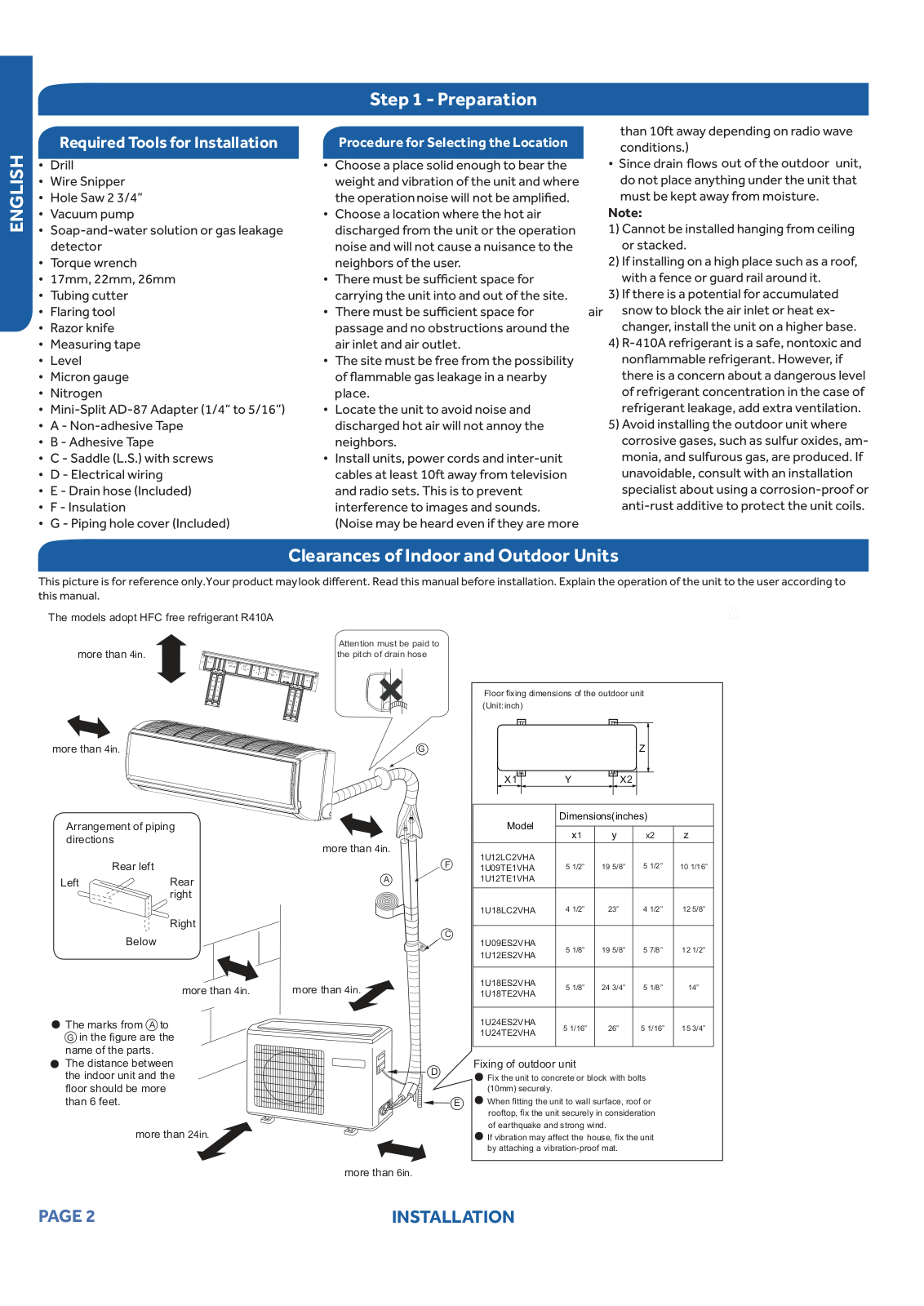
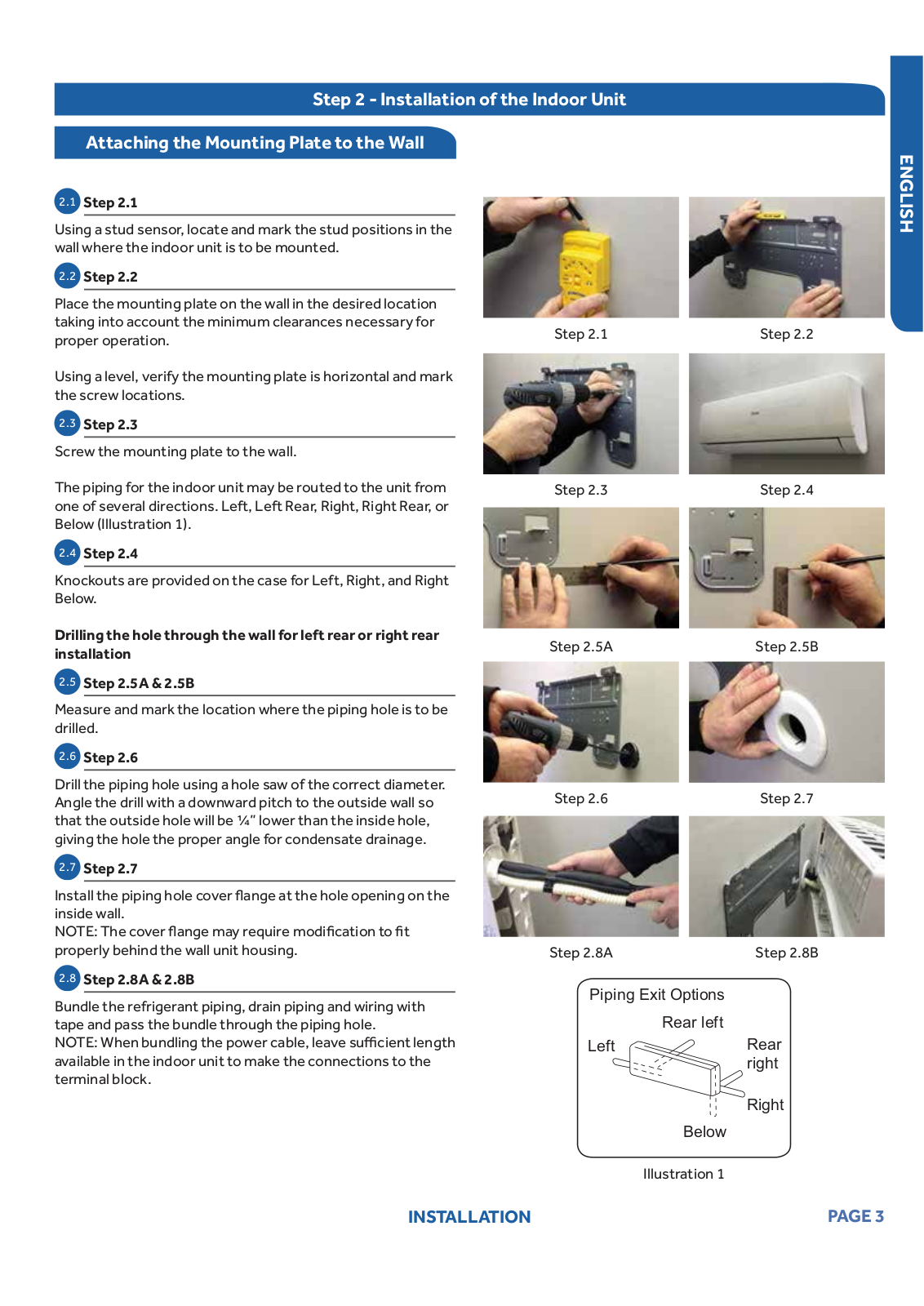
Haier 1u09es2vha-1, 1u12es2vha-1 Owner's Manual
...
Haier Owner's Manual
Download
Specifications and Main Features
Frequently Asked Questions
User Manual
Download
Loading...
+
7
hidden pages
Unhide
You need points to download manuals.
1 point = 1 manual.
You can buy points or you can get point for every manual you upload.
Buy points
Upload your manuals
 Loading...