

Page 1
Instructions/Parts List
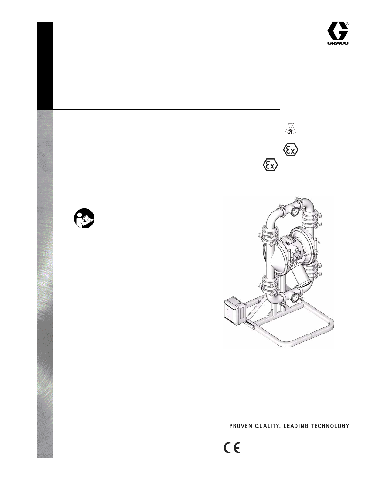
High Sanitation Pumps
For use in sanitary applications.
Models 1590 & 3150 SA__ Sanitary Diaphragm Pump
Models 1590 & 3150 SB__ Sanitary Ball Check Pump
Model 3150 SF__ Sanitary Flapper Check Pump
120 psi (0.8 MPa, 8 bar) Maximum Fluid Working Pressure
120 psi (0.8 MPa, 8 bar) Maximum Air Input Pressure
Important Safety Instructions.
Read all warnings and instructions in
this manual. Save these instructions.
See page 2 for Table of Contents.
II 2 G c T6
310622L
44-03
II 2 G c T6
US and Foreign Patents Pending
US Patent No. 5,368,452
Graco Inc. P.O. Box 1441 Minneapolis, MN 55440-1441
Copyright 2004, Graco Inc. is registered to I.S. EN ISO 9001
Model SA3AAA Shown
TI8760a
Page 2

Contents
Contents
Warning . . . . . . . . . . . . . . . . . . . . . . . . . . . . . . . . . . . 3
Installation . . . . . . . . . . . . . . . . . . . . . . . . . . . . . . . . 5
Operation . . . . . . . . . . . . . . . . . . . . . . . . . . . . . . . . 10
Maintenance . . . . . . . . . . . . . . . . . . . . . . . . . . . . . . 11
Troubleshooting . . . . . . . . . . . . . . . . . . . . . . . . . . . 14
Service . . . . . . . . . . . . . . . . . . . . . . . . . . . . . . . . . . 16
Pump Matrix . . . . . . . . . . . . . . . . . . . . . . . . . . . . . . 25
Parts . . . . . . . . . . . . . . . . . . . . . . . . . . . . . . . . . . . . 26
Accessories . . . . . . . . . . . . . . . . . . . . . . . . . . . . . . 32
3150 Conversion Kits . . . . . . . . . . . . . . . . . . . . . . 32
Model 1590 . . . . . . . . . . . . . . . . . . . . . . . . . . . . . . . 33
Model 3150 . . . . . . . . . . . . . . . . . . . . . . . . . . . . . . . 36
Graco Warranties . . . . . . . . . . . . . . . . . . . . . . . . . . 40
Graco Information . . . . . . . . . . . . . . . . . . . . . . . . . 40
Models
Refer to page 25 to determine the model number of your pump.
Dimensional Drawing . . . . . . . . . . . . . . . . . . . . . 33
Technical Data . . . . . . . . . . . . . . . . . . . . . . . . . . 34
Performance Chart . . . . . . . . . . . . . . . . . . . . . . 35
Dimensional Drawing . . . . . . . . . . . . . . . . . . . . . 36
Technical Data . . . . . . . . . . . . . . . . . . . . . . . . . . 37
Performance Chart . . . . . . . . . . . . . . . . . . . . . . 38
2 310622L
Page 3
Warnings
Warnings
The following general warnings are for the safe setup, use, grounding, maintenance, and repair of this equipment.
The exclamation point symbols alert you to general warnings and the hazard symbols refer to procedure-specific
risks. Refer back to these Warnings. Additional, product-specific warnings may be found throughout the body of this
manual where applicable.
Warning
FIRE AND EXPLOSION HAZARD
Flammable fumes, such as solvent and paint fumes, in work area can ignite or explode. To help prevent
fire and explosion:
• Use equipment only in well ventilated area.
• Eliminate all ignition sources; such as pilot lights, cigarettes, portable electric lamps, and plastic drop
cloths (potential static arc).
• Keep work area free of debris, including solvent, rags and gasoline.
• Do not plug or unplug power cords, or turn power or light switches on or off when flammable fumes
are present.
• Ground equipment and conductive objects in work area. See Grounding instructions.
• Use only grounded hoses.
• Hold gun firmly to side of grounded pail when triggering into pail.
• If there is static sparking or you feel a shock, stop operation immediately. Do not use equipment
until you identify and correct the problem.
PRESSURIZED EQUIPMENT HAZARD
Fluid from the gun/dispense valve, leaks, or ruptured components can splash in the eyes or on skin and
cause serious injury.
• Follow Pressure Relief Procedure in this manual, when you stop operating and before cleaning,
checking, or servicing equipment.
• Tighten all fluid connections before operating the equipment.
• Check hoses, tubes, and couplings daily. Replace worn or damaged parts immediately.
EQUIPMENT MISUSE HAZARD
Misuse can cause death or serious injury.
• Do not exceed the maximum working pressure or temperature rating of the lowest rated system component. See Technical Data in all equipment manuals.
• Use fluids and solvents that are compatible with equipment wetted parts. See Technical Data in all
equipment manuals. Read fluid and solvent manufacturer’s warnings.
• Check equipment daily. Repair or replace worn or damaged parts immediately with genuine Graco
replacement parts only.
• Do not alter or modify equipment.
• For professional use only.
• Use equipment only for its intended purpose. Call your Graco distributor for information.
• Route hoses and cables away from traffic areas, sharp edges, moving parts, and hot surfaces.
• Do not use hoses to pull equipment.
• Comply with all applicable safety regulations.
TOXIC FLUID OR FUMES HAZARD
Toxic fluids or fumes can cause serious injury or death if splashed in the eyes or on skin, inhaled, or swallowed.
• Read MSDS’s to know the specific hazards of the fluids you are using.
• Store hazardous fluid in approved containers, and dispose of it according to applicable guidelines.
310622L 3
Page 4
Warning
Warning
BURN HAZARD
Equipment surfaces and fluids that are heated can become very hot during operation. To avoid severe
burns, do not touch hot fluid or equipment. Wait until equipment/fluid has cooled completely.
PERSONAL PROTECTIVE EQUIPMENT
You must wear appropriate protective equipment when operating, servicing, or when in the operating
area of the equipment to help protect you from serious injury, including eye injury, inhalation of toxic
fumes, burns, and hearing loss. This equipment includes but is not limited to:
• Protective eyewear
• Clothing and respirator as recommended by the fluid and solvent manufacturer
•Gloves
• Hearing protection
4 310622L
Page 5
Installation
General Information
• The typical installation shown in FIG. 3 is only a
guide for selecting and installing system components. Contact your Graco distributor for assistance
in planning a system to suit your needs.
• Always use genuine Graco parts and accessories.
• Reference numbers and letters in parentheses refer
to the callouts in the figures and the parts lists on
pages 26 - 31.
The pump is very heavy (see Technical Data on
pages 34 and 37 for specific weights). If the pump
must be moved, follow the Pressure Relief Proce-
dure on page 10 and have two people lift the pump
by grasping the outlet manifold securely, or use
appropriate lifting equipment. Never have one person
move or lift the pump.
Installation
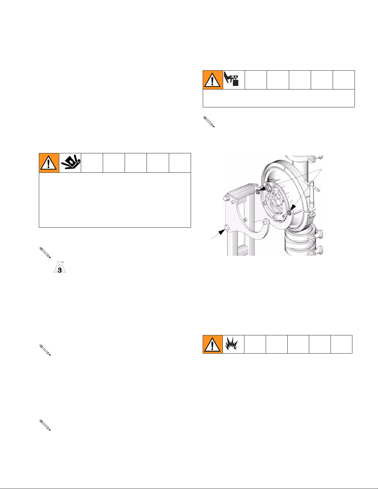
Moving Parts Hazard
Keep clear of moving parts.
Bolts (V) may be loosened to allow the pump, while
still securely mounted to the bracket, to be rotated
for draining or servicing.
659
Leak Detection System
A leak detection system will be included with all
approved pumps. See manual 311200
included with leak detector for leak detector installation instructions.
Tighten Clamps Before First Use
After you unpack the pump, and before you use it for the
first time, check all clamps, and tighten as necessary.
Stand
See pages 30 and 31 for parts.
1. Place the stand assembly on a level surface.
2. Mount the pump securely to the brackets using bolts
(659).
3. Tighten the bolts (V) to hold the slotted bracket in
place. See F
IG. 1.
V
TI8765a
F
IG. 1
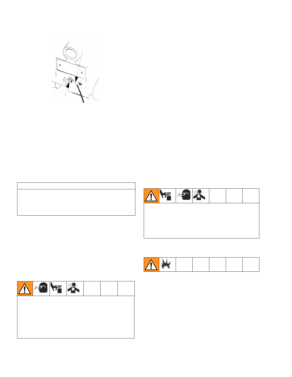
Grounding
To reduce the risk of static sparking, ground the pump
and all other equipment used or located in the pumping
area. Check your local electrical code for detailed
grounding instructions for your area and type of equipment.
• Pump: Connect a ground wire and clamp as shown
in F
IG. 2. Loosen the grounding screw (W). Insert
one end of a 12 ga (1.5 mm²) minimum ground wire
(X) behind the grounding screw and tighten the
screw securely. Connect the clamp end of the
ground wire to a true earth ground. To order a
ground wire and clamp, order part number 222011.
Bolts (V) must be tightened to hold the bracket in
place during operation.
310622L 5
Page 6
Installation
X
W
TI4736A
Ground Wire Connection
F
IG. 2
• Air and fluid hoses: Use only grounded hoses with a
maximum of 500 ft (150 m) combined hose length to
ensure grounding continuity.
• Air compressor: Follow the manufacturer’s recommendations.
• Fluid supply container: Follow the local code.
Mountings
1. Install the air line accessories as shown in FIG. 3.
Mount these accessories on the wall or on a
bracket. Be sure the air line supplying the accessories is grounded.
a. Install an air regulator (C) and gauge to control
the fluid pressure. The fluid outlet pressure will
be the same as the setting of the air regulator.
b. Locate one bleed-type master air valve (B)
close to the pump and use it to relieve trapped
air. Locate the other master air valve (E)
upstream from all air line accessories and use it
to isolate them during cleaning and repair.
c. The air line filter (F) removes harmful dirt and
moisture from the compressed air supply.
2. Install a grounded, flexible air hose (A) between the
accessories and the 1/2 npt(f) pump air inlet (M).
Use a minimum 3/8 in. (9.5 mm) ID air hose. Screw
an air line quick disconnect coupler (D) onto the end
of the air hose (A), and screw the mating fitting into
the pump air inlet snugly.
CAUTION
The pump exhaust air may contain contaminants.
Ventilate to a remote area if the contaminants could
affect your fluid supply. See Air Exhaust Ventilation
on page 8.
• Be sure the mounting surface can support the
weight of the pump, hoses, and accessories, as well
as the stress caused during operation.
• For ease of operation and service, mount the pump
so the air valve cover (2), air inlet, and fluid inlet and
outlet ports are easily accessible.
Air Line
A bleed-type master air valve (B) is required in the
system to relieve air trapped between this valve and
the pump. Trapped air can cause the pump to cycle
unexpectedly, which could result in serious injury
including splashing in the eyes or on the skin, injury
from moving parts, or contamination from hazardous
fluids. See F
IG. 3.
Do not connect the coupler (D) to the fitting until you
are ready to operate the pump. Connecting the coupler too early can result in unintentional operation of
the pump, leading to serious injury from to moving
parts, splashing fluid in the eyes or on the skin, and
contact with hazardous fluids.
Fluid Suction Line
1. Use flexible, grounded fluid hoses (G) where possible.
2. For best sealing results, use a standard Tri-Clamp®
style sanitary gasket of a flexible material such as
EPDM, Buna-N, fluoroelastomer, or silicon.
3. If the fluid inlet pressure to the pump is more than
25% of the outlet working pressure, the ball check
valves will not close fast enough, resulting in inefficient pump operation.
6 310622L
Page 7
Installation
4. At inlet fluid pressures greater than 15 psi (0.1 MPa,
1 bar), diaphragm life will be shortened.
Fluid Outlet Line
A fluid drain valve (J) is required to relieve pressure in
the hose if it is plugged. The drain valve reduces the risk
of serious injury, including splashing in the eyes or on
the skin, or contamination from hazardous fluids when
relieving pressure. Install the valve close to the pump
fluid outlet. See F
IG. 3.
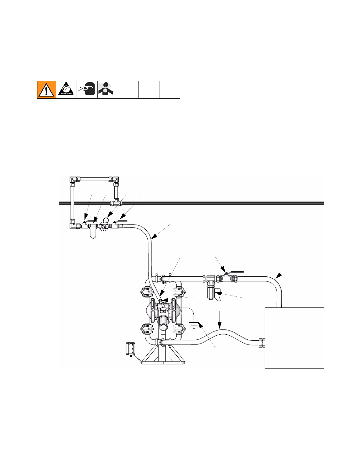
Typical Installation
EF
C
B
5. See the Technical Data on pages 34 and 37 for
maximum suction lift (wet and dry).
1. Use flexible, grounded fluid hoses (L) where possible.
2. For best sealing results, use a standard Tri-Clamp®
style sanitary gasket of a flexible material such as
EPDM, Buna-N, fluoroelastomer, or silicon
3. Install a fluid drain valve (J) near the fluid outlet. See
F
IG. 3.
4. Install a shutoff valve (K) in the fluid outlet line.
Key:
A Air supply line
B Bleed-type master air valve
(required for pump)
C Air regulator
D Air line quick disconnect
E Master air valve (for accessories)
F Air line filter
G Flexible fluid suction line
J Fluid drain valve
K Fluid shutoff valve
L Flexible fluid line
M 1/2 npt (f) air inlet
X Ground wire (required; see page
5 for installation instructions)
FIG. 3 Typical Floor-Mount Installation
A
D
M
K
L
J
G
X
TI8766a
310622L 7
Page 8
Installation
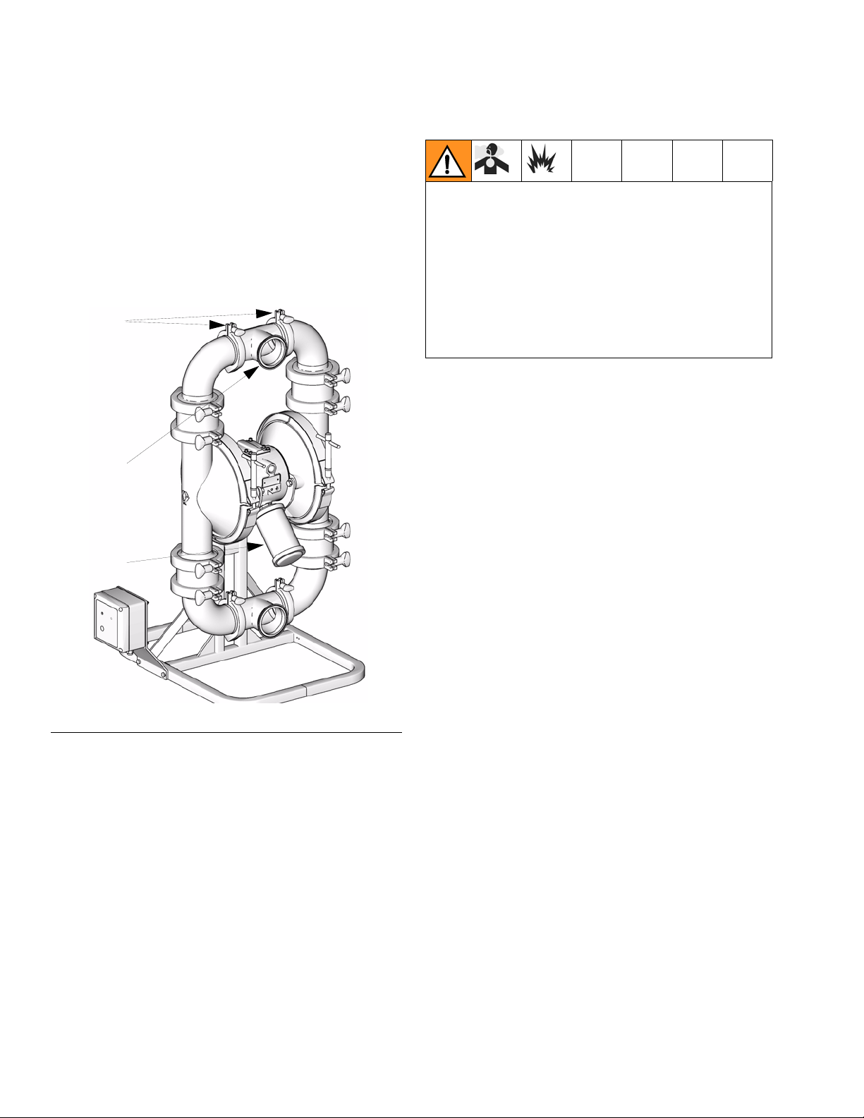
Changing the Orientation of the Fluid Inlet
and Outlet Ports
The pump is shipped with the ports facing the same
direction. To re-orientate the ports into any position:
1. Remove the clamps (130) holding the inlet and/or
outlet tee to the elbows.
2. Rotate the manifold tee (339) and reattach. Install
the clamps (130) and tighten handtight.
130
339
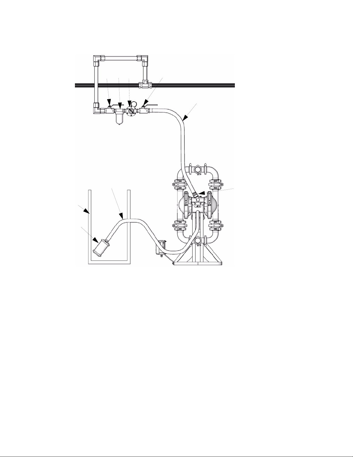
Air Exhaust Ventilation
Be sure the system is properly ventilated for your type
of installation. You must vent the exhaust to a safe
place, away from people, animals, food handling
areas, and all sources of ignition when pumping flammable or hazardous fluids.
Diaphragm failure can cause the fluid being pumped
to exhaust with the air. Place an appropriate container at the end of the air exhaust line to catch the
fluid. See F
The air exhaust port is 3/4 npt(f). Do not restrict the air
exhaust port. Excessive exhaust restriction can cause
erratic pump operation.
To provide a remote exhaust:
1. Remove the muffler (P) from the pump air exhaust
port. See F
IG. 5.
IG. 5.
P
F
IG. 4 Orientation of Fluid Ports
TI5133e
2. Install a grounded air exhaust hose (T) and connect
the muffler (P) to the other end of the hose. The
minimum size for the air exhaust hose is 3/4 in. (19
mm) ID. If a hose longer than 15 ft (4.57 m) is
required, use a larger diameter hose. Avoid sharp
bends or kinks in the hose.
3. Place a grounded container (U) at the end of the air
exhaust line to catch fluid in case of a diaphragm
rupture. See F
IG. 5.
8 310622L
Page 9
Installation
Key:
A Air supply line
B Bleed-type master air valve
BCFE
A
(required for pump)
C Air regulator
D Air line quick disconnect
E Master air valve (for accessories)
F Air line filter
P Muffler
T Grounded air exhaust hose
U Container for remote air exhaust
U
P
F
IG. 5 Venting Exhaust Air
T
D
TI8767a
310622L 9
Page 10
Operation
Operation
Pressure Relief Procedure
1. Shut off the air to the pump.
2. Open any available outbound fluid valve to relieve
fluid pressure from the pump.
3. If fluid is still in the outbound fluid lines, isolate this
fluid as follows:
a. Close the outbound fluid valves.
b. Slowly remove the fluid connections from the
pump, and have a container ready to catch any
fluid that runs out.
Sanitizing the Pump Before First Use
The pump was built and tested using a food grade
lubricant.
It is the user’s responsibility to properly sanitize the
pump before first use. It is up to the user whether this
will include disassembling and cleaning individual parts
or simply flushing pump with a sanitizing solution. As
necessary, follow the steps under Starting and Adjust-
ing the Pump below, under Flushing on page 11, or
under Disassembly in the Service section on pages
19, 21.
2. Check connections to be sure they are tight. Tighten
fluid inlet and outlet connections securely.
3. Place the suction tube (if used) in fluid to be
pumped.
If fluid inlet pressure to the pump is more than
25% of the outlet working pressure, the ball check
valves will not close fast enough, resulting in inefficient pump operation.
4. Place the end of fluid hose (L) into an appropriate
container.
5. Close the fluid drain valve (J).
6. Back out the air regulator (C) knob, and open all
bleed-type master air valves (B, E).
7. If the fluid hose has a dispensing device, hold it
open while continuing with the following step.
8. Slowly increase air pressure with the air regulator
(C) until the pump starts to cycle. Do not exceed the
maximum operating air pressure as listed in the
Technical Data section on pages 34 and 37. Allow
the pump to cycle slowly until all air is pushed out of
the lines and the pump is primed.
Pump Shutdown
At the end of the work shift, relieve pressure.
Starting and Adjusting the Pump
1. Be sure the pump is properly grounded. Refer to
Grounding on page 5.
10 310622L
Page 11
Maintenance
Maintenance
Lubrication
The air valve is designed to operate unlubricated, however if lubrication is desired, every 500 hours of operation (or monthly) remove the hose from the pump air
inlet and add two drops of machine oil to the air inlet.
CAUTION
Do not over-lubricate the pump. Oil is exhausted
through the muffler and could contaminate your fluid
supply or other equipment. Excessive lubrication can
also cause the pump to malfunction.
Flushing
Insert suction tube into cleaning solution. Open air regulator to supply low pressure air to the pump. Run the
pump long enough to thoroughly clean the pump and
hoses. Close the air regulator. Remove the suction tube
from the cleaning solution and drain pump. Place suction tube in the fluid to be pumped.
Flush the pump often enough to prevent the fluid you
are pumping from drying or freezing in the pump and
damaging it. Flushing schedule will be based on what
the pump is being used for. Use a compatible cleaning
solution and always cycle the pump during the entire
flushing process.
Routine Cleaning of Product Contact
Section of Pump
The pump and the system should be cleaned in
accordance with your state sanitary standard
codes and local regulations.
1. Flush the system. See Flushing above.
2. Relieve pressure in the system. See Pressure
Relief Procedure on page 10.
3. Disassemble the fluid section of the pump and
accessories. See Check Valve Repair on page 19
and Diaphragm Repair on page 21.
4. Using a brush or other C.I.P. methods, wash all
product contact pump parts with an alkaline detergent at the manufacturer’s recommended temperature and concentration.
5. Rinse these parts again with water and allow parts
to completely dry.
6. Inspect the parts and reclean any soiled parts.
7. Immerse all product contact parts in an approved
sanitizer before assembly. Leave the parts in the
sanitizer, taking them out only one by one as
needed for assembly. See Check Valve Repair on
page 19 and Diaphragm Repair on page 21.
8. Lubricate the clamps, clamping surfaces, and gaskets with waterproof sanitary lubricant.
Always flush the pump and relieve the pressure before
storing it for any length of time.
9. Circulate the sanitizing solution through the pump
and the system prior to use. Cycle the pump as the
sanitizing solution is circulated.
Tightening Connections
Before each use, check all hoses for wear or damage,
and replace as necessary. Check to be sure all connections are tight and leak-free.
310622L 11
Page 12

Maintenance
Preventive Maintenance Schedule
Establish a preventive maintenance schedule based on
the pump’s service history. This is especially important
for prevention of spills or leakage due to diaphragm
failure.
Operator Maintenance Person
Task
Inspect system for leaks
Depressurize fluid, after
operation
Remove heat from system,
after operation
Inspect diaphragm for wear
Inspect check valve compo-
nents for wear
Check hoses for wear
Check/tighten fluid connections
Check/tighten air connections
Lubricate air valves
Daily Weekly Monthly
✓
✓
✓
✓
✓
✓
✓
✓
The following is a list of recommended maintenance
procedures and frequencies to operate your equipment
safely. Maintenance must be performed by trained personnel per this schedule to assure safety and reliability
of the equipment.
✓
12 310622L
Page 13

Maintenance
310622L 13
Page 14

Troubleshooting
Troubleshooting
• Relieve the pressure before checking or servicing the equipment.
• Check all possible problems and causes before disassembling the pump.
PROBLEM
Pump cycles at stall or fails to hold
pressure at stall.
Pump will not cycle, or cycles once
and stops.
Pump operates erratically. Clogged suction line. Inspect; clear.
CAUSE SOLUTION
Worn check valve balls (541) or
seats (233).
Air valve is stuck or dirty. Disassemble and clean air valve.
Check valve ball (541) severely
worn and wedged in seat (233) or
manifold.
Check valve ball (541) is wedged
into seat (233), due to overpressurization.
Dispensing valve clogged. Relieve pressure and clear valve.
Leak detector has activated a shutdown solenoid
Sticky or leaking balls (541). Clean or replace. See page 19.
Diaphragm ruptured. Replace. See page 21.
Replace. See page 19.
See page 16. Use filtered air.
Replace ball and seat. See page
19.
Follow Pressure Relief Proce-
dure, page 10. Disassemble ball
check assembly and inspect for
damage, see page 19.
Investigate failure and reset leak
detector
Restricted exhaust. Remove restriction.
Air bubbles in fluid. Suction line is loose. Tighten.
Diaphragm ruptured. Replace. See page 21.
Loose inlet manifold, damaged seal
between manifold and seat, damaged gaskets.
14 310622L
Tighten manifold clamps or replace
seats or gaskets. See page 19.
Page 15

Troubleshooting
PROBLEM
Leak in inlet or outlet sanitary fit-
CAUSE SOLUTION
Loose sanitary clamp. Tighten clamp.
ting.
Damaged or worn gasket. Replace gasket.
Misalignment of inlet/outlet hose or
pipe.
Use flexible hoses at pump inlet
and outlet.
Gasket does not seal. Use a standard sanitary gasket of
flexible material such as EPDM,
Buna-N, fluoroelastomer, or silicon.
Fluid in exhaust air. Diaphragm ruptured. Replace. See page 21.
Loose diaphragm plate. Tighten or replace. See page 21.
Pump exhausts excessive air at
stall.
Worn air valve block, plate, pilot
block, u-cups, or pilot pin o-rings.
Repair or replace. See page 16.
Worn shaft seals. Replace. See page 21.
Pump leaks air externally. Air valve cover is loose. Tighten screws. See page 16.
Air valve gasket or air cover gasket
Inspect; replace. See page 16.
is damaged.
Air cover clamps are loose Tighten clamps.
Pump leaks fluid externally from
ball check valves.
Loose manifolds, damaged seal
between manifold and seat, damaged gaskets.
Chattering. Check balls not seating prop-
erly/cleanly due to imbalance
between fluid inlet and outlet line
sizing. Noise is accentuated with
light viscosity fluids.
Tighten manifold clamps or replace
seats or clamps (32). See page 19.
Reduce size/diameter of inlet line
relative to outlet line. Outlet line
size should not exceed pump size.
310622L 15
Page 16

Service
Service
Repairing the Air Valve
Tool Required
• Torque wrench
• Torx (T20) screwdriver or 7 mm (9/32 in.) socket
wrench
• Needle-nose pliers
• O-ring pick
• Lithium base grease
Air Valve Repair Kit 255122 is available. Refer to
Parts on page 31. Parts included in the kit are
marked with ◆ symbol. Use all the parts in the kit
for the best results.
Disassembly
1. Relieve the pressure.
2. With a Torx (T20) screwdriver or 7 mm (9/32 in.)
socket wrench, remove the six screws (103), air
valve cover (102), and gasket (104). See F
IG. 6.
3. Move the valve carriage (105) to the center position
and pull it out of the cavity. Using a needle-nose pliers, pull the pilot block (116) straight up and out of
the cavity. See F
116
◆
IG. 7.
105
◆
TI4616b
FIG. 7
4. Pull the two actuator pistons (111). Remove the
u-cups (110) from the pistons. Pull the pilot pins
(114). Remove the o-rings (115) from the pilot pins.
See F
IG. 8.
FIG. 6
103
102
104
TI4682b
111
110
◆
◆
TI4617b
◆
F
IG. 8
114
115
16 310622L
Page 17

Service
5. Inspect the valve plate (108) in place. If damaged,
use a Torx (T20) screwdriver or 7 mm (9/32 in.)
socket wrench to remove the three screws (103).
Remove the valve plate (108). See F
F
IG. 9
IG. 9.
103
108
◆
TI4618c
6. Inspect the bearings (112, 117) in place. See Parts
on page 31. The bearings are tapered and, if damaged, must be removed from the outside. This
requires disassembly of the fluid section. See page
23.
7. Clean all parts and inspect for wear or damage.
Replace as needed. Reassemble, page 17.
Reassembly
1. If you replaced the bearings (112, 117), reinstall as
explained on page 24. Reassemble the fluid section.
2. Install the valve plate (108) in the cavity, seal down.
Install the three screws (103), using a Torx (T20)
screwdriver or 7 mm (9/32 in.) socket wrench.
Tighten until the screws bottom out on the housing.
See F
IG. 9.
3. Install an o-ring (115) on each pilot pin (114).
Grease the pins and o-rings. Insert the pins into the
bearings, narrow end first. See F
114
IG. 10.
115
◆
111
110
TI4617b
FIG. 10
4. Install u-cups (110) on each actuator piston (111),
so the lips of the packings face the narrow end of
the pistons. See F
IG. 10.
5. Lubricate the u-cups (110) and actuator pistons
(111). Insert the actuator pistons in the bearings,
wide end first. Leave the narrow end of the pistons
exposed. See F
IG. 10.
6. Grease the lower face of the pilot block (116) and
install so its tabs snap into the grooves on the ends
of the pilot pins (114). See F
IG. 11.
7. Grease the lower face of the valve carriage (105).
See F
IG. 11.
◆
310622L 17
Page 18

Service
8. Install the valve carriage (105) so its tabs slip into
the grooves on the narrow end of the actuator pistons (111). See F
116
◆
F
IG. 11
IG. 11.
105
◆
TI4616b
9. Align the valve gasket (104) and cover (102) with
the six holes in the center housing (101). Secure
with six screws (103), using a Torx (T20) screwdriver or 7 mm (9/32 in.) socket wrench. Torque to
50-60 in-lb (5.7-6.8 N•m). See F
IG. 12
F
IG. 12.
103
102
104
◆
TI4682b
18 310622L
Page 19

Check Valve Repair
Service
Disassembly
Reference numbers with an asterisk (*) are
replacement parts. For a complete list of replacement parts see Parts, page 26.
1. Relieve the pressure. Disconnect all hoses.
2. Remove the pump from its mounting. Drain.
3. From the outlet manifold, remove both upper clamps
(132a).
4. Remove outlet manifold leaving elbows (128), gaskets (129), clamps (130), and tee (339) assembled.
5. For 3A Ball Check pumps: remove ball gasket (240).
Remove middle clamp (132c) and ball stop housing
(2XA). Remove middle gasket (240) and ball (541).
Remove lower clamp (132b), seat (2XB), and gasket
(240). Clean all parts and inspect for wear or damage. Replace parts as needed.
128
132a
*240
2XA
132c
*240
*541
2XB
*240
132b
129*
130
3A Ball Check Assembly
TI8768a
FIG. 13
310622L 19
Page 20

Service
For Sanitary Ball Check pumps: remove ball gasket
(242) and ball (541). Remove lower clamp (132b),
seat (233), and gasket (240). Clean all parts and
inspect for wear or damage. Replace parts as
needed.
128
132a
*242
*541
233
*240
132b
129*
130
339*
For Flapper Check pumps: remove gasket (240).
Remove middle clamp (232) and housing (252).
Remove middle gasket (250), flapper retainer (253),
and flapper valve (251). Remove lower clamp
(132b), lower flapper housing (248), and gasket
(240). Clean all parts and inspect for wear or damage. Replace parts as needed.
130
129*
132a
240*
252
232*
250
253
251
248
240*
132b
331*
TI8769a
Sanitary Ball Check Assembly
F
IG. 14
Flapper Check Assembly
TI8770a
FIG. 15
6. Disassemble the outlet manifold. Remove clamps
(130), tee (339), gasket (129), and elbow (128).
Clean all parts and inspect for wear or damage.
Replace parts as needed.
20 310622L
Page 21

Service
7. Repeat for inlet manifold.
Reassembly
Lubricate clamps, clamping surfaces, and gaskets
with waterproof, sanitary lubricant.
1. Reassemble inlet and outlet fluid manifolds in
reverse order. See step 6. Tighten clamps
handtight.
2. Reassemble ball or flapper check assembly in
reverse order. See step 5. Tighten clamps
handtight.
For flapper check, make sure flapper check (251)
is placed properly in housing (248) groove and
flapper retainer (253) is aligned with housing
groove. Ensure that the flapper check moves freely.
Diaphragm Repair
Tools Required
• Torque wrench
• 5/8 in. wrench
• 19 mm open end wrench
• O-ring pick
• Lithium-base grease
• Spanner wrench
Disassembly
1. Relieve the pressure.
2. Remove the manifolds and disassemble the ball
check valves as explained on page 19.
3. Hold fluid covers in place and remove the clamps
(135). Pull the fluid covers (234) off the pump
.
Y
135
234
TI8771a
FIG. 16
4. Non 3A approved diaphragms: With both fluid covers removed, using two 5/8 in. wrenches hold the
wrench flats (Y) on the plates of each diaphragm
assembly and loosen. One diaphragm assembly will
come free and the other will remain attached to the
shaft.
3A approved diaphragms: Diaphragms are assembled handtight. To loosen, grip both diaphragms
securely around the outer edge and rotate counter
clockwise. One diaphragm assembly will come free
and the other will remain attached to the shaft. Continue to step 6.
5. Disassemble the free diaphragm assembly.
6. Remove plate (444) with bolt (143) installed, diaphragm (446), backer (447) if present, and plate
(445)
310622L 21
Page 22

Service
121
.
121
Sanitary Pump
3A Pump
F
IG. 17
121
445
445
446*
447
143
446*
444
Reassembly
1. Install the shaft u-cups (110) so the lips face out of
the housing (101). Lubricate the u-cups. See reas-
Y
sembly of bearing and air gasket removal, page 24.
2. Non 3A approved diaphragms: Assemble dia-
phragm (446), backer (447) if present, and plate
(445) onto plate (444) with screw (143). Rounded
side of plate (445) should face diaphragm. Make
sure the side marked AIR SIDE faces the center
TI8772a
housing.
3A approved diaphragms: Assemble plate (445)
onto diaphragm assembly (446). Round side of
plate should face diaphragm.
Thread locker must be applied to screw (143) and
to threads of 3A diaphragm assembly as shown in
F
IG. 19 for all diaphragm assemblies.
diaphragm plate side:
TI8773a
445121101
high strength thread lock
446*
447
143
444
7. Pull the other diaphragm assembly and the diaphragm shaft (121) out of the center housing (101).
Hold the shaft flats with a 19 mm open end wrench,
and remove the diaphragm assembly from the shaft.
Disassemble the remaining diaphragm assembly.
101
TI4789a
IG. 18
F
8. Inspect the diaphragm shaft (121) for wear or
scratches. If it is damaged, inspect the bearings
(117) in place. If the bearings are damaged, refer to
Bearing and Air Gasket Removal on page 23.
9. Reach into the center housing (101) with an o-ring
pick and hook the u-cups (110), then pull them out
of the housing. This can be done with the bearings
(117) in place. See F
IG. 22.
Sanitary Pump
shaft side:
medium strength thread lock
121101
445
3A Pump
medium strength thread lock
(bolt not shown)
F
IG. 19
TI8774a
446*
TI8775a
10. Clean all parts and inspect for wear or damage.
Replace parts as needed.
3. Screw assembled diaphragm assembly into shaft
(121) and hand tighten.
22 310622L
Page 23

Service
4. Grease the length of the diaphragm shaft (121), and
slide it through the housing (101).
5. Assemble the other diaphragm assembly to the
shaft as explained in step 2.
6. Non 3A approved diaphragms: Using a 5/8 in.
wrench hold the wrench flats of one diaphragm
assembly and torque the other diaphragm to 60-70
ft-lb (81-94 N
•m).
3A approved diaphragms: Grip both diaphragms
securely around the outer edge and handtighten.
Waterproof, sanitary lubricant may be applied to
the clamp (135) and clamping surface of the cover
(234) to ease assembly.
7. Align the fluid covers (234) and the center housing.
Secure the covers with the clamps (135) and hand
tighten.
135
234
Bearing and Air Gasket Removal
Tools Required
• Torque wrench
• 10 mm socket wrench
• Bearing puller
• O-ring pick
• Press, or block and mallet
Disassembly
Do not remove undamaged bearings.
1. Relieve the pressure.
2. Remove the manifolds and disassemble the ball
check valves as explained on page 19.
3. Remove the fluid covers and diaphragm assemblies
as explained on page 21.
TI8771a
F
IG. 20
8. Reassemble the ball check valves and manifolds as
explained on page 19.
If you are removing only the diaphragm shaft
bearing (117), skip step 4.
4. Disassemble the air valve as explained on page 16.
5. Using a 10 mm socket wrench, remove the screws
(122) holding the air covers (120) to the center
housing (101).
119 120 122101
TI4733a
F
IG. 21
6. Remove the air cover gaskets (119). Always replace
the gaskets with new ones.
7. Use a bearing puller to remove the diaphragm shaft
bearings (117), air valve bearings (112) or pilot pin
bearings (113). Do not remove undamaged bearings
310622L 23
Page 24

Service
.
101
112
113
117
TI4731a
F
IG. 22
110*
8. If you removed the diaphragm shaft bearings (117)
reach into the center housing (101) with an o-ring
pick and hook the u-cups (110), then pull them out
of the housing. Inspect the u-cups. See F
IG. 22.
Replace parts as needed.
Reassembly
Adhesive must be applied to the outside surface of
the bearing (112) and the inside surface of bore (Z)
prior to assembly.
.
114 119
TI4730a
IG. 24
F
5. Align the air cover (120) so the pilot pin (114) fits in
the middle hole (M) of the three small holes near the
center of the cover.
120
M114
1. Install the shaft u-cups (110) so the lips face out of
the housing.
2. Insert new bearings (112, 113, and 117) into the
center housing (101), tapered end first. Using a
press or a block and rubber mallet, press-fit the
bearing so it is flush with the surface of the center
housing.
Z
112
113
117
TI4731a
F
IG. 23
101
110*
3. Reassemble the air valve as explained on page 16.
TI4790a
F
IG. 25
6. Apply medium-strength (blue) Loctite® or equivalent
to the threads of the screws (122). Install the screws
(122), handtight. Using a 10 mm socket wrench,
torque the screws oppositely and evenly to 130-150
in-lb (15-17 N
•m). Install the diaphragm assemblies
and fluid covers as explained on page 21.
122
TI4790a
IG. 26
4. Align the new air cover gasket (119) so the pilot pin
(114) protruding from the center housing (101) fits
through the proper hole in the gasket
F
7. Reassemble the ball check valves and manifolds as
explained on page 19.
24 310622L
Page 25

Pump Matrix
3150 Stainless Steel Sanitary Pumps
Pump Matrix
Your Model No. is marked on the pump’s serial plate. To
determine the Model No. of your pump from the following matrix, select the six digits which describe your
pump, working from left to right. The first digit is always
S, designating Graco Sanitary diaphragm pumps. The
remaining five digits define the pump configuration, size,
and materials of construction. For example, a sanitary
Sanitary
Pump
S - (for all pumps)
Pump
Configuration
A 3A Approved 1 1 1/2 x 1 1/2 A 3A Approved
B Ball Check 2 2 x 2
F Flapper Check 3 3 x 3 7 Buna-N 7 Buna-N 3 None
Inlet and Outlet
(in.)
4 4 x 4 8 fluoroelas-
5 3 x 2 F Flapper
PNONE
ball check pump with a three inch inlet and outlet, Santoprene balls and diaphragms, a pump stand, and no
leak detector is model
SB3661. To order replace-
ment parts, refer to the part lists on pages 26 - 31. The
digits in the matrix do not correspond to the reference
numbers in the parts drawing and lists.
Diaphragm Check Ball
Material
A 3A Approved
(EPDM)
6 Santoprene
tomer
®
6 Santoprene
(PTFE)
8 fluoroelas-
tomer
Leak Detector,
Pump Stand
A Leak Detec-
®
1 Pump Stand
tor and Pump
Stand
1590 Stainless Steel Sanitary Pumps
The table below shows all available configurations for 1590 Stainless Steel Sanitary Pumps.
Model Number Pump
Configuration
SABAAA 3A Approved 2 x 2 3A Ball Checks 3A PTFE 3A Approved
SBBAAA Non-3A Approved
No Leak Detector
SBBA11 Non-3A Approved
No Leak Detector
SBBA22 Non-3A Approved
No Leak Detector
Inlet and Outlet
(in.)
2 x 2 3A Ball Checks 3A PTFE 3A Approved
2 x 2 3A Ball Checks (3A) PTFE PTFE
2 x 2 3A Ball Checks Santoprene Santoprene
Check Valve
Style
Check Ball Material
Diaphragm
Material
EPDM
EPDM
310622L 25
Page 26

Parts Drawing
Parts Drawing
3A Pump Shown
128
3
132
3
3
3
*240
2XA
132
*240
541
129* 130
Sanitary Ball Check
3
*242
*541
3
3
Valve Assembly
339*
Sanitary Diaphragm Assembly
3
446*444 143 445135
447*
3
132
3
234
3
132
3
3
3
3
132
3
128
2XB
*240
*240
2XA
132
*240
541
2XB
*240
233
3
*240
135
3
Flapper Check Valve
Assembly
*240
3
252
232
3
200
3
3
*250
*253
251
248
*240
TI7644a
446*
TI4683a
1
2
445
2
1
Apply a high strength thread locker to
diaphragm plate side of screw threads.
2
Apply a medium strength thread locker to
shaft side of screw threads.
3
Apply a waterproof sanitary lubricant to
clamps, clamping surfaces, and gaskets.
TI4729c
*129 130 *331
3
3
TI7645c
26 310622L
Page 27

Parts List
Parts List
Pump Configuration Parts List
Digit Ref.
No.
Model 3150
A 3A Approved Ball Check
132 510490 CLAMP, 4 in. 4
2XB 15H406 SEAT 4
234 249533 COVER, fluid 2
240* 15H460 GASKET, 4 in., EPDM 12
2XA 15H407 STOP, ball 4
B Ball Check
233
234
240* 15H460 GASKET, 4 in., EPDM 4
242* 15D346 GASKET, ball stop 4
F
234 234530 COVER, fluid 2
240* 15H460 GASKET, 4 in., EPDM 8
200 249535 MODULE, flapper;
232 510490 CLAMP, 4 in. 4
248 15D079 HOUSING, lower
250* 15H460 GASKET, 4 in., EPDM 4
251 15D091 VALVE, flapper,
252 15D090 HOUSING, upper
253* 15K693 RETAINER, flapper 4
Model 1590
Part No. Description Qty
15D026 SEAT 4
234530 COVER, fluid 2
Flapper Check
includes items 232,
248, 250, 251, 252,
253
flapper
weldment
flapper
Inlet and Outlet Parts List
Digit Ref.
No.
Model 3150
1 1 1/2 x 1 1/2 in. tee
331* 234536 TEE, inlet 1
339* 234536 TEE, outlet 1
2 2 x 2 in. tee
331* 234534 TEE, inlet 1
339* 234534 TEE, outlet 1
3 3 x 3 in. tee
331* 234532 TEE, inlet 1
339* 234532 TEE, outlet 1
4 4 x 4 in. tee
331* 234535 TEE , inlet 1
339* 234535 TEE, outlet 1
5 3 x 2 in. tee
4
331* 234532 TEE , inlet 1
339* 234534 TEE, outlet 1
Model 1590
4
4
4
All 331* 249893 TEE, Inlet 1
All 339* 249893 TEE, Outlet 1
* Indicates replacement parts.
Part No. Description Qty
2 x 2 in. Tee
3A Approved Ball Check
All 132 15D475 CLAMP, 3 in. 4
All 2XB 15H481 SEAT 4
All 234 249892 COVER, Fluid 2
All 240* 15H459 GASKET, 3 in., EPDM 12
All 2XA 15H482 STOP, Ball 4
* Indicates replacement parts.
310622L 27
Page 28

Parts List
Diaphragm Material Parts List
Digit Ref. Part Description Qty
Model 3150
A
6 253225 Santoprene; includes 110, 446
7 253223 Buna-N; includes 110, 446
8 253222 fluoroelastomer; includes 110, 446
253224 3A Approved, EPDM, Overmolded;
includes 110 and 446
110 112181 U-CUP 2
446*† DIAPHRAGM ASSY 2
445 189298 PLATE, diaphragm
(air side)
110 112181 U-CUP 2
446*† DIAPHRAGM 2
143 15D021 BOLT 2
444 15D018 PLATE, diaphragm 2
445 189298 PLATE, diaphragm 2
110 112181 U-CUP 2
446*† DIAPHRAGM 2
143 15D021 BOLT 2
444 15D018 PLATE, diaphragm 2
445 189298 PLATE, diaphragm 2
110 112181 U-CUP 2
446*† DIAPHRAGM 2
143 15D021 BOLT 2
444 15D018 PLATE, diaphragm 2
445 189298 PLATE, diaphragm 2
2
Model Ref. Part Description Qty
Model 1590
255058 3A Approved, EPDM, Overmolded;
includes 110 and 446
110 112181 U-CUP 2
446*† DIAPHRAGM
ASSEMBLY
445 15K448 PLATE, Diaphragm (air
SABAAA
SBBAAA
255059 Santoprene; includes 110 and 446
110 112181 U-CUP 2
446*† DIAPHRAGM 2
143 15D021 BOLT 2
444 15K288 PLATE, Diaphragm (fluid
SBBA22
445 15K448 PLATE, Diaphragm (air
255060 PTFE; includes 110 and 446 and 447
110 112181 U-CUP 2
446*† DIAPHRAGM 2
447*† BACKER 2
143 15D021 BOLT 2
444 15K288 PLATE, Diaphragm (fluid
SBBA11
445 15K448 PLATE, Diaphragm (air
All diaphragm modules above include 2 u-cups
(110) to replace seals around shaft (121). See page
30.
side)
side)
side)
side)
side)
2
2
2
2
2
* Indicates replacement parts.
† Indicates a recommended spare part.
28 310622L
Page 29

Check Ball Material Parts List
Digit Ref. Part Description Qty
Model 3150
A 3A Approved, PTFE
541*† 112359 BALL 4
F Flapper check
NONE
6 Santoprene
541*† 112361 BALL 4
7 BUNA-N
541*† 15B492 BALL 4
8 fluoroelastomer
541*† 15B491 BALL 4
Model 1590
3A Approved PTFE
SABAAA
SBBAAA
SBBA11
SBBA22 541*† 112421 BALL 4
541*† 112419 BALL 4
Santoprene
Parts List
* Indicates replacement parts.
† Indicates a recommended spare part.
310622L 29
Page 30

Parts Drawing
Parts Drawing
122 120
2
116
103
3
102
104◆
◆114115◆
105◆
111
110◆
147
1
Apply medium strength adhesive to outside
surface of piston bearing and inside surface of
center housing bore.
2
Apply a medium strength thread locker to
screw threads and torque to 130-150 in-lbs
(14.6-16.9 N•m).
3
Torque to 50-60 in-lb (5.7-6.8 N•m).
119
164
660
661
637
103
108◆
101
Z
TI4680c
112
113
121
110◆
117
1
659
V
638
TI8068a
30 310622L
Page 31

Parts List
Parts List
Air Section Parts
Ref. Part Description Qty.
101 15K010 HOUSING, center 1
102 15K697 HOUSING, cover 1
103 116344 SCREW, mach, torx 10
104◆ 188618 GASKET, cover 1
105◆ 248904 CARRIAGE, manifold assy 1
108◆ 15H178 VALVE, plate 1
110◆ 112181 U-CUP, packing 4
111 188612 PISTON, actuator 2
112 188613 BEARING, piston 2
113 188611 BEARING, pin 2
114 188610 PIN, push 2
115◆ 157628 O-RING 2
116◆ 188614 BLOCK, pilot 1
117 188609 BEARING, shaft 2
119 188603 GASKET air cover 2
120 15D016 COVER, machined air, 3150 2
15G694 COVER, machined air, 1590 2
121 189245 SHAFT 1
122 112178 SCREW 12
147 103778 PLUG 2
162▲ 188621 TAG, warning 1
164 15G332 MUFFLER 1
◆ Parts included in Air Valve Repair Kit 255122
(purchase separately).
▲ Replacement Danger and Warning labels, tags, and
cards are available at no cost.
Fluid Section Parts
Ref. Part Description Qty.
Model 3150
128 234531 ELBOW 4
129 15H459 GASKET, sanitary, EPDM, 3 in. 4
130 15D475 CLAMP, sanitary, 3 in. 4
132 510490 CLAMP, sanitary, 4 in. 8
135 15G323 CLAMP, sanitary, diaphragm 2
Model 1590
128 249894 ELBOW
129 15H598 GASKET, sanitary, EPDM,
2 in.
130 500984 CLAMP, sanitary, 2 in.
132 15D475 CLAMP, sanitary, 3 in.
135 15H341 CLAMP, sanitary, dia-
phragm
Leak Detector and Pump Stand Parts List
Digit Ref. Part Description Qty
A 3A Approved, Leak Detector and Pump Stand
3150 and 1590 SABAAA
637 15D990 LEAK DETECTOR 1
638 15F694 FRAME 1
659 15D008 BOLT, sst 4
660 15H971 GASKET, upper 1
661 15H972 GASKET, lower 1
1 Pump Stand Only 3150 and 1590 SBBAAA,
SBBA11, SBBA22
638 15F694 FRAME 1
659 15D008 BOLT, sst 4
3 Bare Pump
none
4
4
4
8
2
* Indicates replacement parts.
† Indicates a recommended spare part.
310622L 31
Page 32

Accessories
Accessories
15D990 Leak Detector
Sensor and control package that monitors the diaphragm condition. In case of diaphragm failure, the control will provide an audible alarm and relay contacts for
remote alarms or solenoids. See Leak Detector manual
311200.
To be approved, a leak detection system must
be used on the pump. Any pump with a leak detec-
tor installed is NOT Atex approved.
3150 Conversion Kits
15H461 3A Approved Ball Check
Conversion Kit
Converts flapper check valve to 3A ball check valve.
Includes four seats and four ball stops. Balls need to be
ordered separately.
Part No. Description
15B406 SEAT, ball 4
15H460 GASKET, 4 in. 12
510490 CLAMP, 4 in. 4
15H407 STOP, ball 4
Qty.
15D989 Flapper Valve Conversion Kit
Converts ball check valve to flapper check valve.
Includes four flapper assemblies. See Flapper Valve
Assembly, page 26.
Part No. Description
513548 GASKET, 4 in. 8
249535 MODULE, flapper 4
Qty.
15E285 Sanitary Ball Check Conversion Kit
Converts flapper check valve to sanitary ball check
valve. Includes four seats and four ball stops. Balls need
to be ordered separately.
Part No. Description
15D026 SEAT, ball 4
15D346 GASKET, ball stop 4
Qty.
32 310622L
Page 33

Model 1590
Dimensional Drawing
Model 1590
24.9 in.
(632.5 mm)
35.8 in.
(909.3 mm)
22.0 in.
(558.8 mm)
TI8778a
8.6 in.
(218.4 mm)
23.5 in.
(596.9 mm)
TI8777a
310622L 33
Page 34

Model 1590
Model 1590
Technical Data
Maximum fluid working pressure . . . . . . . . . . . . . . . . . . . 120 psi (0.8 MPa, 8 bar)
Air pressure operating range . . . . . . . . . . . . . . . . . . . . . . 20-120 psi (0.14-0.8 MPa, 1.4-8 bar)
Maximum air consumption . . . . . . . . . . . . . . . . . . . . . . . . 125 scfm
Air consumption at 70 psi air inlet pressure/60 gpm. . . . .
Maximum free-flow delivery . . . . . . . . . . . . . . . . . . . . . . . 100 gpm (378.5 l/min)
Maximum pump speed . . . . . . . . . . . . . . . . . . . . . . . . . . . 200 cpm
* Gallons (Liters) per cycle . . . . . . . . . . . . . . . . . . . . . . . .
Maximum suction lift . . . . . . . . . . . . . . . . . . . . . . . . . . . . . 28 ft (8.5 m) wet, 15 ft (4.57 m) dry
Maximum size pumpable solids . . . . . . . . . . . . . . . . . . . . 5/8 in. (15.9 mm)
** Maximum Noise Level at 100 psi, full flow . . . . . . . . . . 90 dBa
** Sound Power Level. . . . . . . . . . . . . . . . . . . . . . . . . . . . 103 dBa
** Noise Level at 70 psi and 50 cpm. . . . . . . . . . . . . . . . . 85 dBa
50 scfm (see chart)
0.5 (1.96)
Maximum fluid operating temperature is based on the
following maximum diaphragm, ball, and o-ring tempera-
ture ratings.. . . . . . . . . . . . . . . . . . . . . . . . . . . . . . . . . . . .
Air inlet size . . . . . . . . . . . . . . . . . . . . . . . . . . . . . . . . . . .
Wetted parts
***All fluid contact materials are FDA-compliant and meet the United States Code of Federal Regulations (CFR)
Title 21, Section 177.
All fluid contact materials are FDA-compliant.
Wetted materials on all models . . . . . . . . . . . . . . . . . . . .
Wetted material depending on model. . . . . . . . . . . . . . . .
CAUTION:
Santoprene® may be used only with non-fatty, non-oily foods or alcohols up to 15%.
Non-wetted external parts . . . . . . . . . . . . . . . . . . . . . . . .
Weight . . . . . . . . . . . . . . . . . . . . . . . . . . . . . . . . . . . . . . . 97 lb (44 kg)
Santoprene® is a registered trademark of the Monsanto Co.
PTFE 220°F (104.4°C)
Santoprene® 180°F (82.2°C)
3A Approved EPDM 275°F (135°C)
0.5 in. npt(f)
316 SST, 3A Approved EPDM, PTFE,
Santoprene®, 3A Approved EPDM, PTFE
300 series stainless steel, polyester (labels), LDPE foam
(gasket)
Loctite® is a registered trademark of the Loctite Corporation.
* Displacement per cycle may vary based on suction condition, discharge head, air pressure, and fluid type.
** Noise levels measured with the pump mounted on the stand. Sound power measured per ISO Standard 9614-1.
*** The pump user must verify that the construction materials meet their specific application requirements.
34 310622L
Page 35

Model 1590
Performance Chart
Test Conditions: Pump tested in water with inlet submerged
Model 1590
To find Fluid Outlet Pressure
(psi/MPa/bar) at a specific fluid flow (gpm/lpm) and
operating air pressure (psi/MPa/bar):
1. Locate fluid flow rate along bottom of chart.
2. Follow vertical line up to intersection with selected
fluid outlet pressure curve.
3. Follow left to scale to read fluid outlet pressure.
1590 3A Performance Chart
120
(8.4, 0.84)
100
(7, 0.7)
80
(5.5, 0.55)
60
(4.2, 0.42)
psi (bar, MPa)
Fluid Outlet Pressure
40
(2.8, 0.28)
20
(1.4, 0.14)
To find Pump Air Pressure
(scfm or m
3
/min) at a specific fluid flow (gpm/lpm) and
operating air pressure (psi/MPa/bar):
1. Locate fluid flow rate along bottom of chart.
2. Read vertical line up to intersection with selected air
consumption curve.
3. Follow left to scale to read fluid outlet pressure.
120
(3.4)
100
(2.8)
80
(2.2)
/min)
60
(1.7)
40
(1.1)
20
(0.6)
3
scfm (m
Air Consumption
0
0
20
(76)
40
(152)
60
(227)
80
(303)
100
(379)
120
(454)
TI8646
Fluid Flow
gpm (lpm)
TI8647
310622L 35
Page 36

Model 3150
Model 3150
Dimensional Drawing
3A Ball Check Valve Pumps
22.0 in
(558.8 mm)
TI4929d
Sanitary Ball Check Valve Pumps
28.4 in.
(721.4 mm)
6.5 in.
(165.1 mm)
(955.0 mm)
23.5 in.
(596.9 mm)
Flapper Check Valve Pumps
37.6 in.
TI7610c
28.3 in.
(718.8 mm)
6.5 in.
(165.1 mm)
19.3 in.
(490.2 mm)
36 310622L
37.5 in.
(952.5 mm)
TI4685d
29.5 in.
(749.3 mm)
5.9 in.
(149.9 mm)
19.3 in.
(490.2 mm)
38.1 in.
(967.7 mm)
TI4928d
Page 37

Model 3150
Technical Data
Maximum fluid working pressure . . . . . . . . . . . . . . . . . . . 120 psi (0.8 MPa, 8 bar)
Air pressure operating range . . . . . . . . . . . . . . . . . . . . . . 20-120 psi (0.14-0.8 MPa, 1.4-8 bar)
Maximum air consumption . . . . . . . . . . . . . . . . . . . . . . . . 175 scfm
Air consumption at 70 psi air inlet pressure/60 gpm. . . . .
Maximum free-flow delivery . . . . . . . . . . . . . . . . . . . . . . . 150 gpm ( 570 l/min)
Maximum pump speed . . . . . . . . . . . . . . . . . . . . . . . . . . . 145 cpm
* Gallons (Liters) per cycle . . . . . . . . . . . . . . . . . . . . . . . .
Maximum suction lift . . . . . . . . . . . . . . . . . . . . . . . . . . . . . Flapper 10 ft (3.5 m) wet, 5 ft (1.75 m) dry
Maximum size pumpable solids . . . . . . . . . . . . . . . . . . . .
** Maximum Noise Level at 100 psi, full flow . . . . . . . . . . 90 dBa
** Sound Power Level . . . . . . . . . . . . . . . . . . . . . . . . . . . . 103 dBa
** Noise Level at 70 psi and 50 cpm . . . . . . . . . . . . . . . . . 85 dBa
50 scfm (see chart)
1.03 (3.90)
Ball 18 ft (5.5 m) wet, 9 ft (2.75 m) dry
Flapper 2.5 in. (63.5 mm)
Ball 1.0 in. (25.4 mm)
Model 3150
Maximum fluid operating temperature is based on the
following maximum diaphragm, ball, and seat temperature
ratings. . . . . . . . . . . . . . . . . . . . . . . . . . . . . . . . . . . . . . . .
Air inlet size . . . . . . . . . . . . . . . . . . . . . . . . . . . . . . . . . . .
Wetted parts
***All fluid contact materials are FDA-compliant and meet the United States Code of Federal Regulations (CFR)
Title 21, Section 177.
Wetted materials on all models. . . . . . . . . . . . . . . . . . . . .
Wetted material depending on model . . . . . . . . . . . . . . . .
CAUTION:
Santoprene® may be used only with non-fatty, non-oily foods or alcohols up to 15%.
Non-wetted external parts. . . . . . . . . . . . . . . . . . . . . . . . .
Weight . . . . . . . . . . . . . . . . . . . . . . . . . . . . . . . . . . . . . . . 145 lb (66 kg)
Santoprene® is a registered trademark of the Monsanto Co.
PTFE 220°F (104.4°C)
Santoprene® 180°F (82.2°C)
Buna-N 180°F (82.2°C)
fluoroelastomer 250°F (121.1°C)
3A Approved EPDM 275°F (135°C)
0.5 in. npt(f)
316 SST, 3A Approved EPDM
316 SST, Santoprene®, Buna-N (Nitrile), fluoroelastomer,
3A Approved EPDM, PTFE
300 series stainless steel, polyester (labels), LDPE foam
(gasket)
Loctite® is a registered trademark of the Loctite Corporation.
* Displacement per cycle may vary based on suction condition, discharge head, air pressure, and fluid type.
** Noise levels measured with the pump mounted on the stand. Sound power measured per ISO Standard 9614-1.
*** The pump user must verify that the construction materials meet their specific application requirements.
310622L 37
Page 38

Model 3150
Model 3150
Performance Chart
Test Conditions: Pump tested in water with inlet submerged
To find Fluid Outlet Pressure
(psi/MPa/bar) at a specific fluid flow (gpm/lpm) and
operating air pressure (psi/MPa/bar):
1. Locate fluid flow rate along bottom of chart.
2. Follow vertical line up to intersection with selected
fluid outlet pressure curve.
3.Follow left to scale to read fluid outlet pressure.
3150 3A Performance Chart
120
(8.4, 0.84)
100
(7, 0.7)
80
(5.5, 0.55)
60
(4.2, 0.42)
psi (bar, MPa)
Fluid Outlet Pressure
40
(2.8, 0.28)
20
(1.4, 0.14)
0
60
40
20
0
(76)
(152)
(227)
Fluid Flow
80
(303)
gpm (lpm)
To find Pump Air Pressure
(scfm or m
3
/min) at a specific fluid flow (gpm/lpm) and
operating air pressure (psi/MPa/bar):
1. Locate fluid flow rate along bottom of chart.
2. Read vertical line up to intersection with selected air
consumption curve.
3. Follow left to scale to read fluid outlet pressure.
150
(4.2)
125
(3.5)
100
(2.8)
100
(379)
120
(454)
140
(531)
75
(2.1)
50
(1.4)
25
(0.7)
160
(606)
Air Consumption
/min)
3
scfm (m
TI8644a
TI8645a
38 310622L
Page 39

Model 3150
310622L 39
Page 40

Graco Warranties
Graco Standard Pump Warranty
Graco warrants all equipment manufactured by Graco and bearing its name to be free from defects in material and workmanship on the date of
sale to the original purchaser for use. With the exception of any special, extended, or limited warranty published by Graco, Graco will, for a period
of five years from the date of sale, repair or replace any part of the equipment determined by Graco to be defective. This warranty applies only
when the equipment is installed, operated and maintained in accordance with Graco’s written recommendations.
This warranty does not cover, and Graco shall not be liable for general wear and tear, or any malfunction, damage or wear caused by faulty
installation, misapplication, abrasion, corrosion, inadequate or improper maintenance, negligence, accident, tampering, or substitution of
non-Graco component parts. Nor shall Graco be liable for malfunction, damage or wear caused by the incompatibility of Graco equipment with
structures, accessories, equipment or materials not supplied by Graco, or the improper design, manufacture, installation, operation or maintenance
of structures, accessories, equipment or materials not supplied by Graco.
This warranty is conditioned upon the prepaid return of the equipment claimed to be defective to an authorized Graco distributor for verification of
the claimed defect. If the claimed defect is verified, Graco will repair or replace free of charge any defective parts. The equipment will be returned
to the original purchaser transportation prepaid. If inspection of the equipment does not disclose any defect in material or workmanship, repairs will
be made at a reasonable charge, which charges may include the costs of parts, labor, and transportation.
THIS WARRANTY IS EXCLUSIVE, AND IS IN LIEU OF ANY OTHER WARRANTIES, EXPRESS OR IMPLIED, INCLUDING BUT NOT LIMITED
TO WARRANTY OF MERCHANTABILITY OR WARRANTY OF FITNESS FOR A PARTICULAR PURPOSE.
Graco’s sole obligation and the buyer’s sole remedy for any breach of warranty shall be as set forth above. The buyer agrees that no other remedy
(including, but not limited to, incidental or consequential damages for lost profits, lost sales, injury to person or property, or any other incidental or
consequential loss) shall be available. Any action for breach of warranty must be brought within six years of the date of sale.
Graco makes no warranty, and disclaims all implied warranties of merchantability and fitness for a particular purpose in connection with
accessories, equipment, materials or components sold but not manufactured by Graco. These items sold, but not manufactured by Graco (such as
electric motors, switches, hose, etc.), are subject to the warranty, if any, of their manufacturer. Graco will provide purchaser with reasonable
assistance in making any claim for breach of these warranties.
In no event will Graco be liable for indirect, incidental, special or consequential damages resulting from Graco supplying equipment hereunder, or
the furnishing, performance, or use of any products or other goods sold hereto, whether due to a breach of contract, breach of warranty, the
negligence of Graco, or otherwise.
FOR GRACO CANADA CUSTOMERS
The parties acknowledge that they have required that the present document, as well as all documents, notices and legal proceedings entered into,
given or instituted pursuant hereto or relating directly or indirectly hereto, be drawn up in English. Les parties reconnaissent avoir convenu que la
rédaction du présente document sera en Anglais, ainsi que tous documents, avis et procédures judiciaires exécutés, donnés ou intentés, à la suite
de ou en rapport, directement ou indirectement, avec les procédures concernées.
Extended Product Warranty
Graco warrants all 205, 307, 515, 716, 1040, 1590, 2150, 3150, and 3275 air valve center sections to be free from defects in material and
workmanship for a period of fifteen years from date installed in service by the original purchaser. Normal wear of items such as packings or seals
are not considered to be defects in material and workmanship.
Five years Graco will provide parts and labor.
Six to Fifteen years Graco will replace defective parts only.
Graco Information
TO PLACE AN ORDER, contact your Graco distributor, or call this number to identify the distributor closest to you.
1-800-328-0211 Toll Free
612-623-6921
612-378-3505 Fax
All written and visual data contained in this document reflects the latest product information available at the time of publication.
Graco reserves the right to make changes at any time without notice.
This manual contains English. MM 310622
Graco Headquarters: Minneapolis
International Offices: Belgium, China, Japan, Korea
GRACO INC. P.O. BOX 1441 MINNEAPOLIS, MN 55440-1441
www.graco.com
5/2004, Revised 4/2007
 Loading...