

Page 1

Page 2

TA1100/TA1600
Signal-to-Noise: >102dB below rated output “A” weighted
CMRR: >65dB at 1kHz
Input Impedance: 47kΩ per phase balanced
47kΩ unbalanced
Gain: 29dB maximum
Damping Factor: 350 (to 1kHz); 150 (to 10kHz); 18 (to 100kHz)
Controls & Switches: Front Panel: Power Switch and Level Controls
Indicators: Power Lamp, Clip/Thermal/Protect LEDs
Connectors: Input: Balanced:
1
/4” Tip Ring Sleeve
Unbalanced RCA
Output:
1
/4” Phone, Spring Clip
Headphone:
1
/4”
Power: IEC 320
Dimensions: 19”W x 8 1/2”D x 3 1/2”H (2 rack space)
(48cm x 25cm x 8.9cm)
Net Weight: 22 lbs
(9.98kg)
TA 1100
Power Rating: 1kHz, 0.1% THD
50 wpc into 4Ω
40 wpc into 8Ω
Frequency Response: ± 0.1dB, 20Hz to 20kHz
+0/-3dB, 1.0Hz to 100kHz
Slew Rate: 20V/µs
Input Sensitivity for rated output power:
Unbalanced: 0.640V RMS (8Ω), 0.510V (4Ω)
Balanced: 0.320V (8Ω), 0.250V (4Ω) per phase
Power Consumption: 40VA quiescent
TA 1600
Power Rating: 1kHz, 0.1% THD
75 wpc into 4Ω
60 wpc into 8Ω
Frequency Response: ± 0.1dB, 20Hz to 20kHz
+0/-3dB, 1.0Hz to 300kHz
Slew Rate: 100V/µs
Input Sensitivity for rated output power:
Unbalanced: 0.780V RMS (8Ω), 0.620V (4Ω)
Balanced: 0.390V (8Ω), 0.310V (4Ω) per phase
Power Consumption: 60VA quiescent
– i –
Specifications
Page 3

ii
NOTICE - IMPORTANT SAFETY INFORMATION
1. Read Instructions
All the safety and operating instructions of your Hafler equipment should be read before power is applied to the equipment.
2. Retain Owner's Manual
These safety and operating instructions should be retained for
future reference.
3. HEED WARNINGS
All warnings on the equipment and in the operating instructions are important and should be followed.
4. FOLLOW INSTRUCTIONS
All operating and use instructions are important and should be
followed.
5. HEAT
The equipment should be kept away from areas of high temperature, i.e., heater vents, radiators, stoves/ovens, fireplaces,
etc.
6. VENTILATION
The equipment should be used in an area suitable for proper
ventilation. Care should be taken not to impede airflow in and
around the cabinet. Do not mount on a carpeted shelf or in a
sealed enclosure. Allow for proper clearance above the equipment.
7. WATER AND MOISTURE
The equipment should not be used in or around water, such as
a bathtub, sink, or swimming area. Also, the equipment should
not be used in areas prone to flooding, such as a basement.
8. POWER SOURCES
The equipment should be connected only to a power source of
the same voltage and frequency as that listed on the rear panel
above the power cord entry point.
9. POWER CORD PROTECTION
Power cords should be arranged so they do not interfere with
the movement of objects in the room: people, fan blades, utility carts, etc. Also, care should be taken that the cord is not
pinched or cut, and placed so it is not in danger of being
pinched or cut, as in under a rug, around a tight corner, etc.
10. POWER CORD GROUNDING
The power supply cord is of a three wire grounded type,
designed to reduce the risk of electric shock sustained from a
live cabinet. It is assumed to be of suitable length for most uses
of the equipment. The use of extension cords and power strips
is discouraged unless they are of suitable rating to deliver the
required total current for safe operation of all connected
equipment. Furthermore, extension cords or power strips must
provide the same three wire grounded connection. It is important that the blades of the equipment’s plug be able to fully insert
into the mating receptacle.
Never remove the round grounding
pin on the plug in an attempt to mate to a two wire ungrounded receptacle:
use a grounding adapter with the grounding tab or
wire suitably connected to earth ground.
11. NON-USE PERIODS
During periods of extended non-use, the power cord should be
unplugged from the power source.
12. CLEANING
The equipment should be cleaned only as detailed in the operating instructions.
13. OBJECT AND LIQUID ENTRY
Care should be taken so that objects and/or liquids, such as
cleaning fluids or beverages, are not spilled into the enclosure of
the equipment.
14. DAMAGE REQUIRING SERVICE
Hafler equipment should be serviced by qualified service personnel when:
A. The power supply cord or plug has been damaged, or
B. Objects have fallen, or liquid has been spilled into the
equipment, or
C. The equipment has been exposed to rain, or
D. The equipment does not appear to operate normally or
exhibits a marked change in performance, or
E. The equipment has been dropped, or the enclosure has
been damaged.
15. SERVICING
The user should not attempt to service the equipment beyond
that which is described in the operating instructions. All other service should be referred to qualified service personnel.
16. CARTS AND STANDS
The equipment should be used with carts or stands only of
sufficient strength and stability for the use intended.
An equipment and cart combination should be moved with
care. Quick stops and starts, excessive force, and uneven sur
faces.
The lightning flash with arrowhead symbol within an equilateral triangle
is intended to alert the user to the presence of uninsulated "dangerous voltage" within the product's enclosure, that may be of sufficient magnitude
to constitute a risk of electric shock to persons.
The exclamation point within an equilateral triangle is intended to alert
the user of the presence of important operating and maintenance (servicing) instructions in the literature accompanying the appliance.
CAUTION
RISK OF ELECTRIC SHOCK
DO NOT OPEN
WARNING:
DO NOT EXPOSE THIS EQUIPMENT TO RAIN OR MOISTURE.
TO PREVENT FIRE OR SHOCK HAZARD
!
Page 4
1. LEA LAS INSTRUCCIONES
Todas las instrucciones de seguidad y operación de su equipo
Hafler, deben ser leídas antes de que el equipo sea conectado
dléctricamente.
2. CONSERVE EL MANUAL DEL PROPIETARIO
Estas instrucciones de seguridad y operación, deben ser conservadas para futuras referencias.
3. CUADROS DE ADVERTENCIAS
Todas las advertencias en el equipo y en las instrucciones de
operación, son importantes y deben ser seguidas.
4. SIGA LAS INSTRUCCIONES
Todas las instrucciones de uso y operación son importantes y
deben ser seguidas.
5. CALOR
El equipo debe ser mantenido lejos de areas de alta temperatura,
como por ejemplo: ventilaciones de calentadores, radiadores, estufas/hornos, hogueras, etc.
6. VENTILACION
El equip debe ser usado en áreas con ventilación adecuada.
Deben er tornadas las precauciones necesarias para no impedir
el flujo de aire dentro y alrededor del aparato.
7. AGUA Y HUMEDAD
El equipo no debe ser usado en el agua ó alrededor de ésta, tales
como en una bañera, tanque o áreas de nado. También, el
equipo no debe ser usado en áreas propensas a inundaciones,
tales como en un sótano.
8. FUENTES DE PODER
El equipo debe ser conectado a una fuente de poder del mismo
voltaje y frecuencia que el indicado en el panel trasero sobre el
punto de entrada del cable de corriente.
9. PROTECCION DEL CABLE DE CORRIENTE
Los cables de corriente deben ser dispuestos de forma tal que no
interfieran con el movimiento de objetos en la sala: personas,
aspas de ventilación, carretillas, etc. También, es necesario tener
cuidado de que el cable no esté punzado o cortado, y debe estar
ubicado de forma tal que esto no ocurra, como podría suceder
debajo de una alfombra o al pasar el cable por una esquina
aguda, etc.
10. ATERRAMIENTO DEL CABLE DE CORRIENTE
El cable de corriente es del tipo aterrado de tres hilos, diseñado
para reducir el riesgo de una descarga eléctrica procendent de un
chasis energizado. Se asume que su longitud es suficiente para la
mayoría de usos del equipo. El uso de extensiones y multienchufes no es recomendado, a menos que tengan el amperaje
adecuado para poder suministrar la corrioente requerida pra la
operación segura de todo el equipo conectado. Aun más, las
extensiones deben proveer de la misma conección aterrada de
tres hiles. Es importante que el enchufe se pueda introducir completamente en el receptáculo.
Nunca remeva el pin de aterramiento en un intento por conectar el cable en un receptáculo
de dos hilos no aterrado:
use un adaptador de aterramiento que
esté adecuadamente conectado a un punto de tierra.
11. PERIODOS SIN USO
Durante períodos prolongados sin uso del equipo, el cable de
corriente debe ser desconectado de la fuente de electrixidad.
12. LIMPIEZA
El equip debe ser limpiado solo en la forma que se detalla en las
instruccione opera`Å+˘ción.
13. INTRODUCCIÓN DE OBJETOS Y LIQUIDO
Deben ser tornadas precauciones con el fin de que objetos y/ó
líquidos, tales como fluidos de limpieza y gaseosas, no sean derramados dentro del chassis del aparato.
14. DAÑOS QUE REQUIEREN DE SERVICIO
Los equipos Hafler deben ser llevados a servicio por personal
calificado cuando:
A. El cable de corriente ó el enchufe haya sido dañado, ó
B. Objetos ó líquido hayan sido introducidos ó derramado en
el equipo, ó
C. El equipo haya sido expuesto a lluvia, ó
D. El equipo aparenta no operar normalmente ó exhibe un
marcado cambio en su desempeño, ó
E. El equipo se ha caído, o el chassis ha sido golpeado.
15. SERVICIO
El usuario no deberá intentar darle servicio al equipo más allá de
lo que está descrito en el instructivo de operación. Todo lo
demás, deberá ser referido a servicio por personal calificado.
16. CARRETILLAS Y SOPORTES
El equipo podrá ser usado con carretillas y soportes que tengan la
fortaleza y estabilidad suficiente para el uso previsto.
La combinación equipo/carretilla deberá ser movida con cuidado. Rápidas paradas y arranques, excesiva fuerza y superficies
imparejas, pueden causar el volcamiento del conjunto de carretilla/equipo.
ADVERTENCIA – INFORMACION DE SEGURIDAD IMPORTANTE
El símbolo de flecha relámpago dentro de un triángulo equilátero, es para alertar al usario de la presencia de “voltajes peligrosos” no aislados en el interior del aparato, los cuales pueden
ser de suficiente magnitud para constituir un riesgo de choque
eléctrico a las personas.
El símbolo de exclamación dentro de un triángulo equilátero, es
para alertar al usuario de la presencia de instrucciones importantes de operación y mantenimiento (servicio) en la documentación que acompaña al equipo.
iii
P E L I G R O
RIESGO DE DESCARGA
´
ELECTRICA NO ABRIR.
PRECAUCIONS:
Para Prevenir el incendio o la descarga electrica, no
exponer este equipo a la lluvia o a la humedad
´
´
!
Page 5

iv
PERFORMANCE SPECIFICATIONS ..................................................................................................................................................i
SAFETY PRECAUTIONS ..................................................................................................................................................................ii
INTRODUCTION ............................................................................................................................................................................1
DESIGN FEATURES ..........................................................................................................................................................................2
INSTALLATION
Location ....................................................................................................................................................................................3
AC Line......................................................................................................................................................................................3
Input..........................................................................................................................................................................................3
Output ......................................................................................................................................................................................3
Hum ..........................................................................................................................................................................................3
OPERATION
Power Switch ............................................................................................................................................................................5
Level Controls............................................................................................................................................................................5
TA1100 ....................................................................................................................................................................................5
TA1600 - Short Circuit Protection ............................................................................................................................................5
Warm Up ..................................................................................................................................................................................5
Cleaning and Maintenance........................................................................................................................................................5
SERVICE POLICY & LIMITED WARRANTY ......................................................................................................................................6
Table of Contents
Page 6

– 1 –
The Hafler TA1100 and TA1600 are two channel, two rack height, convection-cooled, MOSFET power amplifiers suitable
for use in the most demanding applications of critical listening and instrument amplification. These amplifiers offer the
same outstanding sonic quality and reliability that has contributed to Hafler’s enviable reputation within professional
recording studios and broadcast facilities all over the world.
This manual contains information on using the TA1100 and TA1600 amplifiers. It is organized into two main sections.
“Installation” covers the location and connection of the amplifier in the system. Like many precision components, careful
attention to the initial setup can yield dividends in higher performance and trouble-free use. “Operation” covers the controls and features of the amplifiers and how to use them to get the best effect.
The circuitry used in the TA 1600 is the latest refinement of our patented trans•
nova
(TRANSconductance NOdal Voltage
Amplifier, US Patent 4,467,288) circuit. It has been proven to offer sound quality to satisfy the most analytic audiophile or
the most demanding professional. The natural sound and realistic reproduction have made trans•
nova
amplifiers preferred
in many critical installations. Since our pioneering use of MOSFETs in the DH-200 amplifier, they have proven extremely
fault tolerant even in abusive situations. This sturdiness enables the amplifier to drive reactive speaker loads without the
performance and sound penalties imposed by elaborate protection schemes.
The TA1100 trans•
ana
circuitry has been very successful in bringing new levels of clarity and intelligibility to many broad-
cast facilities and headphone monitoring installations. Even at low power levels, the trans•
ana
MOSFET amplifier circuit
imitates the accuracy and warmth of it’s bigger brother, the TA1600 trans•
nova.
Specialized circuits in both amplifiers prevent damage to the amplifiers and speakers, without affecting the audio signal. A
soft start circuit prevents sending potentially destructive turn-on and turn-off transients to the speakers. A thermal sensing
network monitors the heatsink and transformer temperature, and shuts down the amplifier to protect from excessive operating heat. The need for internal fuses has been eliminated; a sensing circuit monitors the output and shuts down operation
when it detects a short in the output load.
The front panel has controls for input level adjustment. In addition, LED indicators give a visual representation of the operating status of each channel. Any type of fault - whether it is clipping, short protection, or thermal standby - will be indicated with a red LED.
Hafler manufactures additional Professional and Home Theatre amplifiers and monitors that offer an extreme level of performance and advanced technology. Visit our website at www.hafler.com for more information.
Introduction
Page 7

2
Design Features
1. Input level control
2. Clip/Thermal/ Protect LED
3. Power switch
4. Headphone jack
1. Balanced 1/4” input
2. Unbalanced RCA input
3. IEC line cord connector
4. Line fuse compartment
5. 1/4” mono speaker output
6. Spring clip output
1 2 4 3 2 1
1
2
4
3 5
6
5 2 1
Page 8

LOCATION
The TA1100 and TA1600 power transformer can generate a substantial magnetic field, so caution should be exercised in
the placement of low level components such as a tape deck, mixer or mic preamp to avoid inducing noise in the low level
circuitry. The amplifiers can also produce considerable heat in normal operation, so the primary consideration when determining a location for the amplifiers is to allow for adequate ventilation. The large heatsinks provide unrestricted airflow, but
care must be taken to keep the slots in the bottom panel and top cover clear. Use the rubber feet if the amplifier is placed
on a flat surface. If the amplifier is mounted in an equipment rack, make sure adjacent equipment does not impede cool air
flow.
We recommend leaving one rack space above and below the amplifier for proper cooling.
Inadequate ventilation can shorten component life, especially when other equipment raises the ambient air temperature, so
circulating fans should be considered in tight quarters.
AC LINE
The TA1100 and TA1600 operate from a 120 volt, 60Hz AC power line. Connection is made by a 16 gauge, IEC Type 320,
grounded line cord. For safety considerations only a properly grounded (earthed) receptacle should be used. If a grounded
circuit is not available do not break off the ground pin; use the proper adapter plug for a two wire receptacle. The line fuse
mounted on the rear panel will interrupt power to the amplifier if an internal fault is detected. If this fuse blows, replace it
with the same type and rating fuse only. The correct replacement fuse value is printed on the rear panel of the amplifier. If
the new fuse blows, this is an indication of a fault with the amplifier. Servicing should be performed only by a qualified
technician.
INPUT
The input jacks on the back of the amplifier will accept either
1
/4” balanced, 1/4” unbalanced, or RCA unbalanced inputs. If
both jacks are used simultaneously, the
1
/4” input will automatically activate internal switches and disconnect the RCA
input, so that only the
1
/4” input remains operational.
OUTPUT
Speakers can be connected to the amplifier with
1
/4” mono plugs, or bare wires into spring clip connectors. Polarity of the
1
/4” connectors is Tip (+) and Sleeve (-).
HUM
It is not unusual to experience objectionable hum in even the simplest audio systems. If you are hearing hum in the
speakers or headphones, here is a very effective test that will help you troubleshoot your system, and eliminate the
problem:
CAUTION: DO NOT PERFORM THIS TEST WITH HEADPHONES . PROTECT YOUR EARS. MONITOR THE
OUTPUT OF YOUR AMPLIFIER AT A SAFE DISTANCE AWAY FROM FULL- RANGE SPEAKERS.
Hum Test:
Step 1:
Turn off the amplifier, turn both level controls all the way down, disconnect all input cables, disconnect head-
phones.
Step 2: Connect a full- range speaker to the output of One CHANNEL of the amplifier.
Step 3: Turn on amplifier. Slowly turn up the level controls and listen for hum. Turn level control back down and turn off
the amplifier. If the hum level was low, then the amplifier is not the source of the hum problem.
Step 4: Repeat this procedure on the remaining channel.
3
Installation
Page 9
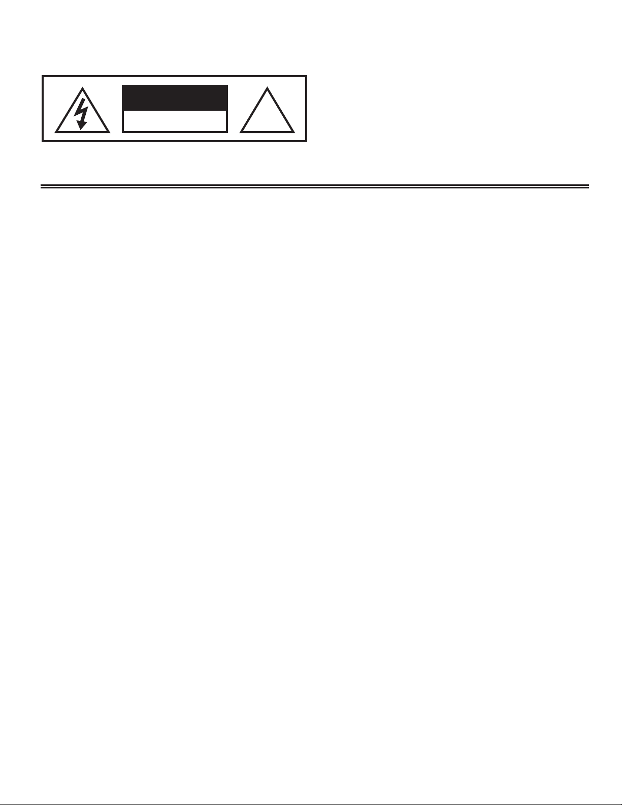
1/4" TRS Balanced Input
Check output of source unit for proper signal polarity
Tip = (+)
Ring = (–)
Sleeve = GND
1/4" TRS Unbalanced Input
Tip
= (+)
Sleeve = GND
4
Operation
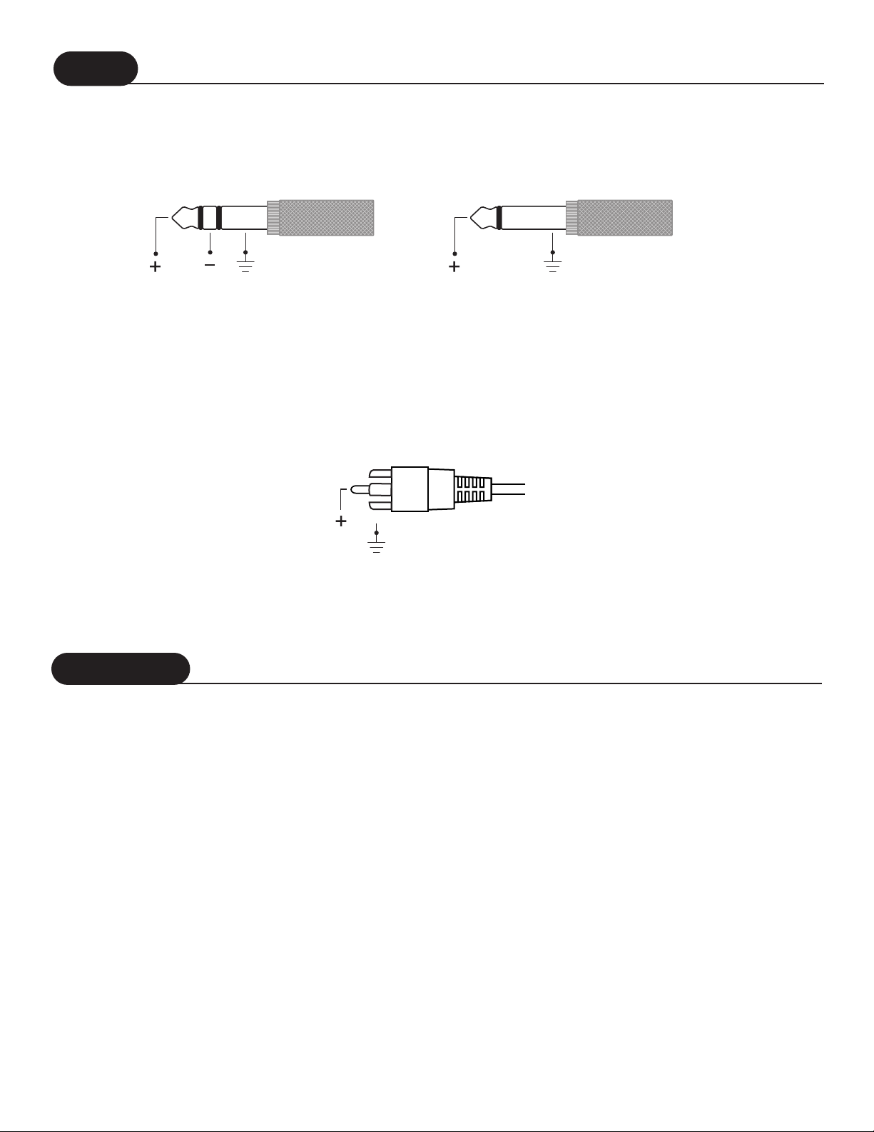
RCA Unbalanced Input
Tip = (+)
Shell = GND
Input
Tip
Shell
POWER SWITCH
The POWER switch is located on the front panel of the amplifier. An internal lamp indicates when it is turned on.
Standard practice is to turn the amplifier on last and off first when switching components to prevent sending damaging transients to the speakers.
It is possible to leave the power switch in the on position and switch the amplifier remotely through a power distribution block
or preamp switched outlet. When doing so make sure the switch is rated for the current required by the amplifier.
LEVEL SETUP
The input sensitivity for each channel can be adjusted individually using the Level Controls on the front panel. Set up the
amplifier Level Controls such that the amplifier clipping LED’s light occasionally when the source unit level control is turned
up approximately
2
/
3
to
3
/
4
full on.
Turning up the amplifier level controls any further than this will not make the amplifier any
louder! It will only increase the noise floor (hum and hiss)
TA 1100 - SHORT CIRCUIT PROTECTION
In the event of a short in the speaker load or cables, the protection circuit will automatically shut down the amplifier and
illuminate the red LED. When the short is removed, the red LED will turn off, and the signal will return to normal.
Tip Ring Sleeve Tip Sleeve
1/4" TRS Unbalanced Input1/4" TRS Balanced Input
Page 10

TA 1600 - SHORT CIRCUIT PROTECTION
The TA1600 amplifier circuit has no need for sonically degrading voltage and current limiting circuits. To protect the amplifier from problems which may occur in the speaker line there is an overload detection circuit.
In the event of a short in the speaker load or cables, the speaker detection circuit will shut down that channel and light
the red front panel indicator. If this happens, correct the fault and turn the amplifier off, then back on. This will reset
the amplifier.
WARM UP
In order to achieve the best sonic performance from the amplifier, we recommend letting it warm up for 1 hour before beginning any critical listening. The amplifier may not deliver its full potential sound quality before this time has passed. Many users
leave Hafler amplifiers on indefinitely to ensure the best operation without delay.
CLEANING AND MAINTENANCE
There is no requirement for regular maintenance on the electronic components of the amplifier. If the case becomes soiled it
can be cleaned using a soft cloth and a mild detergent, such as spray window or glass cleaner. If the amplifier is located in a
particularly dusty environment cleaning the inside with compressed air or vacuuming every 18 to 24 months is sufficient.
Troubleshooting
No Sound
Adjust the system headroom. First, turn the
source unit level control up to
3
/
4
maximum. Next, turn the amplifier level
controls down until the clip LED activates
occasional, only during peak audio events.
SYMPTOM DIAGNOSIS REMEDY
No Power
Check the line fuse on the back panel, line
cord connections, power strip switch, wall
receptacle switch, and breaker.
Check connections, substitute with known
working source and cables and repair or
replace as
necessary.
Disconnect existing speakers and wires and
replace with known working speakers and
wires. If amplifier works, check and repair
wiring and speakers as needed.
Line voltage not present
RCA or
1
/
4
” input from
source unit is not connected
or not functioning properly
Speaker leads are shorted, or
speakers are blown
Too much system Gain
Protection circuit has
activated
Reset the amplifier by turning the power
off, then back on again. If protection
activates again, check for shorted speaker
wires or blown speakers.
No Sound - Red LED on
TA1600
Hum in Speakers or
Headphones
Ground Loop
(Balanced Input Only)
Try disconnecting the ground wire on both
1
/
4
”balanced cables
5
Page 11

Please contact Hafler for any Warranty issues.
Hafler offers the following limited warranty on Hafler products.
• Length of Warranty
1 year on TA1100 and TA1600
90 days on all B-Stock electronics (receipts are required)
• What is Covered
This warranty applies only to products sold to the original owner (non-transferable). This only applies to units sold in the
Continental United States. You are required to have a copy of the receipt stating the customer's name, dealer name, product purchased and date of purchase.
• Products found to be defective during the warranty period will be repaired or replaced (with product deemed to be
equivalent) at Hafler's discretion.
• What is NOT Covered
1. Damage caused by accident, abuse, improper operation, water, theft
2. Service performed by anyone other than Hafler or an Authorized Hafler service center
3. Any product purchased outside the United States (please contact your local dealer)
4. Shipping charges to get the unit to Hafler
5. Any product which has had the serial number defaced, altered, or removed
• Limit on Implied Warranties
Any implied warranties including warranties of fitness for use and merchantability are limited in duration to the period
of the express warranty set forth above. Some states do not allow limitations on the length of an implied warranty, so
this limitation may not apply. No person is authorized to assume for Hafler any other liability in connection with the
sale of the product.
•
How to obtain service or technical support
Please call 1-800-669-9899 for Rockford/Hafler support. You must obtain an RA # (return authorization number) to
return any products to Hafler. You are responsible for shipment of product to Hafler.Always include proof of purchase.
Mark RA# on outside of shipping carton.
Rockford Corporation
Hafler Division - receiving amps.
2055 E. 5th Street
Tempe, Arizona 85281
6
Service Policy & Limited Warranty
Page 12

®
HAFLER
A DIVISION OF
ROCKFORD CORPROATION
546 SOUTH ROCKFORD DRIVE
TEMPE, ARIZONA 85281 U.S.A.
480-967-3565 / 1-888-HAFLER1
WWW.HAFLER.COM
M.J.T. 6/00
MADE IN TAIWAN
 Loading...