

Page 1

Catalog Number 8990
Sigma 900 MAX Refrigerated Sampler
INSTRUMENT MANUAL
07/03 4ed
Page 2

Page 3

Catalog Number 8990
Sigma 900 MAX Refrigerated Sampler
INSTRUMENT MANUAL
© Hach Company, 2002, 2003. All rights reserved. Printed in the U.S.A.
eac 07/03 4ed
Page 4

Visit http: //www.hach.com
Page 5

Table of Contents
Safety Precautions .................................................................................................................................................... 7
Specifications ............................................................................................................................................................ 9
Section 1 Introduction ...................................................................................................................................... 15
1.1 Controller Cover ................................................................................................................................................ 15
1.2 Front Panel........................................................................................................................................................ 15
1.2.1 Keypad Description.................................................................................................................................. 16
1.2.2 Liquid Crystal Display.............................................................................................................................. 16
1.2.3 Internal Humidity Indicator....................................................................................................................... 17
1.3 Interface Connectors......................................................................................................................................... 18
1.3.1 Receptacle Caps ..................................................................................................................................... 18
1.4 Principle of Operation ....................................................................................................................................... 19
1.4.1 Liquid Sensing ......................................................................................................................................... 19
INSTALLATION.................................................................................................................................................... 21
Section 2 Installation......................................................................................................................................... 23
2.1 Unpacking the Instrument ................................................................................................................................. 23
2.2 Selecting the Installation Site ............................................................................................................................ 23
2.3 Installing the Pump Tube in the Sensor Body ................................................................................................... 24
2.3.1 Attaching the Intake Line ......................................................................................................................... 25
2.3.1.1 Attaching the Vinyl Tubing .......................................................................................................... 25
2.3.1.2 Attaching the Teflon®-Lined Tubing ........................................................................................... 25
2.3.2 Setting Up the Intake Line and Strainer................................................................................................... 26
2.4 Choosing Bottle and Retainer Configurations ................................................................................................... 26
2.5 Setting Up the Bottles ....................................................................................................................................... 27
2.5.1 One-Bottle Sampling ............................................................................................................................... 27
2.5.2 Two- and Four-bottle Sampling................................................................................................................ 27
2.5.3 Eight-, 12-, or 24-bottle Sampling ............................................................................................................ 28
2.6 Installing the Distributor (Multiple Bottle Operation).......................................................................................... 29
2.6.1 Distributor Arm Alignment........................................................................................................................ 30
2.7 Installing the Full-Bottle Shut-Off Device (Single Bottle Operation) .................................................................. 31
2.8 Power Connections ........................................................................................................................................... 31
2.9 Auxiliary Receptacle Pin Identification .............................................................................................................. 32
2.9.1 Splitter Interface....................................................................................................................................... 33
OPERATION......................................................................................................................................................... 35
Section 3 Basic Programming Setup............................................................................................................ 37
3.1 Initial Power-Up of Sampler............................................................................................................................... 37
3.2 Basic Programming Setup ................................................................................................................................ 37
3.3 Advanced Sampling .......................................................................................................................................... 49
Section 4 Sensor Setup.................................................................................................................................... 61
4.1 Downlook Ultrasonic Sensor ............................................................................................................................. 61
4.1.1 Downlook Ultrasonic Sensor Connection ................................................................................................ 61
4.1.2 Downlook Ultrasonic Sensor Programming ............................................................................................. 61
Page 3
8990TOC.fm Table of Contents
Page 6

Table of Contents
4.1.3 Downlook Ultrasonic Sensor Calibration ................................................................................................. 61
4.1.3.1 Liquid Depth................................................................................................................................ 61
4.1.3.2 Sensor Height ............................................................................................................................. 62
4.1.3.3 Setting the Invisible Range ......................................................................................................... 62
4.2 Submerged Area/Velocity Sensor ..................................................................................................................... 63
4.2.1 Submerged Area/Velocity Sensor Connection......................................................................................... 63
4.2.2 Submerged Area/Velocity Sensor Programming ..................................................................................... 63
4.2.3 Submerged Area/Velocity Submerged Area/Velocity Sensor Calibration ................................................ 64
4.3 Submerged Pressure Sensor............................................................................................................................ 65
4.3.1 Submerged Pressure Sensor Connection ............................................................................................... 65
4.3.2 Submerged Pressure Sensor Programming............................................................................................ 66
4.3.3 Submerged Pressure Sensor Calibration ................................................................................................ 66
Section 5 Optional Device Installation.......................................................................................................... 69
5.1 Rain Gauge ....................................................................................................................................................... 69
5.1.1 Rain Gauge Programming ....................................................................................................................... 70
5.2 pH Probe........................................................................................................................................................... 70
5.2.1 pH Probe Connection .............................................................................................................................. 70
5.2.2 pH Probe Programming ........................................................................................................................... 71
5.2.3 pH Probe Calibration ............................................................................................................................... 71
5.3 ORP Probe........................................................................................................................................................ 72
5.3.1 ORP Probe Connection ........................................................................................................................... 72
5.3.2 ORP Probe Programming........................................................................................................................ 73
5.3.3 ORP Probe Calibration ............................................................................................................................ 73
5.3.3.1 ORP Preamplifier/Junction Box Calibration ................................................................................ 73
5.4 Dissolved Oxygen Probe................................................................................................................................... 74
5.4.1 Dissolved Oxygen Probe Connection ...................................................................................................... 74
5.4.2 Dissolved Oxygen Probe Programming................................................................................................... 74
5.4.3 Dissolved Oxygen Probe Temperature Programming ............................................................................. 75
5.4.4 Dissolved Oxygen Probe Calibration ....................................................................................................... 75
5.5 Conductivity Probe ............................................................................................................................................ 76
5.5.1 Conductivity Probe Connection ............................................................................................................... 76
5.5.2 Conductivity Probe Programming ............................................................................................................ 76
5.5.3 Conductivity Temperature Programming ................................................................................................. 76
5.5.4 Conductivity Probe Calibration ................................................................................................................ 77
Section 6 Communication Setup.................................................................................................................... 79
6.1 RS232 Cable..................................................................................................................................................... 79
6.1.1 RS232 Connection .................................................................................................................................. 79
6.1.2 RS232 Programming ............................................................................................................................... 79
6.2 Modem .............................................................................................................................................................. 80
6.2.1 Modem Connection ................................................................................................................................. 80
6.2.2 Modem Programming .............................................................................................................................. 80
6.2.2.1 Cellular Communication Option .................................................................................................. 81
6.2.2.2 Reliable Communications ........................................................................................................... 82
6.2.2.3 Cellular Modem Scheduling........................................................................................................ 82
6.2.2.4 Cellular Modem Scheduling Basis .............................................................................................. 83
6.2.2.5 Cellular Modem Triggering ......................................................................................................... 84
6.2.2.6 Pager Option............................................................................................................................... 84
6.2.2.7 Reporting Devices ...................................................................................................................... 85
Page 4
Table of Contents
8990TOC.fm
Page 7

Table of Contents
6.3 4–20 mA Option ................................................................................................................................................ 87
6.3.1 4–20 mA Connection ............................................................................................................................... 87
6.3.2 4–20 mA Programming............................................................................................................................ 87
6.3.3 4–20 mA Calibration ................................................................................................................................ 88
6.4 Alarm Relays..................................................................................................................................................... 89
6.4.1 Alarm Relays Connection ........................................................................................................................ 90
6.4.2 Alarm Relays Programming..................................................................................................................... 91
6.4.2.1 Trouble Alarms ........................................................................................................................... 91
6.4.2.2 Set Point Alarms ......................................................................................................................... 91
6.5 Analog Inputs .................................................................................................................................................... 93
6.5.1 Analog Inputs Connection ....................................................................................................................... 93
6.5.2 Analog Inputs Programming .................................................................................................................... 94
MAINTENANCE................................................................................................................................................... 95
Section 7 Maintenance ..................................................................................................................................... 97
7.1 Cleaning the Sampler ....................................................................................................................................... 97
7.1.1 Cleaning the Sampler Cabinet................................................................................................................. 97
7.1.2 Cleaning the Sample Bottles ................................................................................................................... 97
7.1.3 Cleaning the Intake Tubing and Pump Tubing ......................................................................................... 97
7.1.4 No Lubrication Required .......................................................................................................................... 97
7.2 Pump Tubing Maintenance................................................................................................................................ 97
7.2.1 Tubing Life Estimates............................................................................................................................... 97
7.2.2 Replacing Pump Tubing........................................................................................................................... 98
7.3 Upgrades, Repairs, General Maintenance ........................................................................................................ 98
Electrostatic Discharge (ESD) Considerations ................................................................................................. 99
7.4 Internal Maintenance Items............................................................................................................................... 99
7.5 Removing and Opening the Controller.............................................................................................................. 99
7.6 Re-installing the Bottom Panel........................................................................................................................ 100
7.7 Circuit Board Identification .............................................................................................................................. 101
7.8 Replacing the Fuse ......................................................................................................................................... 103
7.9 Motor/Gear Box............................................................................................................................................... 103
7.10 Internal Desiccant Module ............................................................................................................................ 103
7.10.1 Replacing the Desiccant...................................................................................................................... 103
7.11 Memory Battery ............................................................................................................................................ 104
Appendix A Quick Start Guides ......................................................................................................................... 105
Sigma 900 MAX Refrigerated Sampler Main Menu Flow Chart ..................................................................... 105
Sigma 900 MAX Refrigerated Sampler Setup Flow Chart.............................................................................. 106
Sigma 900 MAX Refrigerated Sampler Options Flow Chart........................................................................... 107
Sigma 900 MAX Refrigerated Sampler Advanced Sampling Flow Chart ....................................................... 108
Sigma 900 MAX Refrigerated Sampler Alarms Flow Chart ............................................................................ 109
Sigma 900 MAX Refrigerated Sampler Calibration Flow Chart (1 of 2) ......................................................... 110
Sigma 900 MAX Refrigerated Sampler Calibration Flow Chart (2 of 2) ......................................................... 111
Appendix B Programming Features .................................................................................................................. 113
Review All Items ............................................................................................................................................. 113
Running a Program ........................................................................................................................................ 113
Displaying Data .............................................................................................................................................. 113
Page 5
8990TOC.fm Table of Contents
Page 8

Table of Contents
Selecting the Channel .................................................................................................................................... 114
Tabular or Graph Format ................................................................................................................................ 114
Graph Manipulation ........................................................................................................................................ 115
Graphic Display Averaging ............................................................................................................................. 115
Sample History ............................................................................................................................................... 115
Options Menu Features .................................................................................................................................. 116
Setting the Time and Date.............................................................................................................................. 116
Volume Calibration ......................................................................................................................................... 116
Data Log ......................................................................................................................................................... 119
Logging Intervals ............................................................................................................................................ 119
Dynamic Memory Allocation ........................................................................................................................... 120
Data Logging Configuration ............................................................................................................................ 121
Diagnostics ..................................................................................................................................................... 121
Load Program................................................................................................................................................. 124
Screen Saver Mode ........................................................................................................................................ 124
Flow Totalizer ................................................................................................................................................. 125
Appendix C Troubleshooting and Error Messages............................................................................................ 127
Error Messages .............................................................................................................................................. 127
Trouble Alarm Conditions, Causes, and Solutions ......................................................................................... 129
Downlook Ultrasonic Sensor Troubleshooting................................................................................................ 130
pH Troubleshooting ........................................................................................................................................ 131
Sigma 900 MAX Refrigerated Sampler Troubleshooting Issues .................................................................... 132
Appendix D How to Calculate Pulses/Counts.................................................................................................... 133
Appendix E Exploded Drawings ........................................................................................................................ 137
Sigma 900 MAX Refrigerated Sampler Assembly Drawing (1 of 3) ............................................................... 137
Sigma 900 MAX Refrigerated Sampler Assembly Drawing (2 of 3) ............................................................... 138
Sigma 900 MAX Refrigerated Sampler Assembly Drawing (3 of 3) ............................................................... 139
Sigma 900 MAX Refrigerated Composite Sampler Assembly........................................................................ 140
Sigma 900 Composite Refrigerator Assembly................................................................................................ 141
Sigma 900 MAX Refrigerated Discrete Sampler Assembly............................................................................ 142
Sigma 900 Discrete Refrigerator Assembly.................................................................................................... 143
Transition Tray Assembly ............................................................................................................................... 144
Sigma 900 MAX Refrigerated Sampler Reference Dimensions ..................................................................... 145
GENERAL INFORMATION .............................................................................................................................. 147
Parts and Accessories .......................................................................................................................................... 149
Contact Information for U.S.A. and Outside Europe ............................................................................................. 153
Contact Information for Europe............................................................................................................................. 154
Warranty ............................................................................................................................................................... 155
Page 6
Table of Contents
8990TOC.fm
Page 9
Safety Precautions
Please read this entire manual before unpacking, setting up, or operating this instrument.
Pay particular attention to all danger and caution statements. Failure to do so could result in serious injury to the
operator or damage to the equipment.
To ensure the protection provided by this equipment is not impaired, do not use or install this equipment in any
manner other than that which is specified in this manual.
Use of Hazard Information
If multiple hazards exist, this manual will use the signal word (Danger, Caution, Note) corresponding to the
greatest hazard.
DANGER
Indicates a potentially or imminently hazardous situation which, if not avoided, could result in
death or serious injury.
CAUTION
Indicates a potentially hazardous situation that may result in minor or moderate injury.
NOTE
Information that requires special emphasis.
Precautionary Labels
Read all labels and tags attached to the instrument. Personal injury or damage to the instrument could occur if
not observed.
This symbol, if noted on the instrument, references the instruction manual for operation
and/or safety information.
This symbol, when noted on a product enclosure or barrier, indicates that a risk of electrical shock
and/or electrocution exists and indicates that only individuals qualified to work with hazardous voltages
should open the enclosure or remove the barrier.
This symbol, when noted on the product, identifies the location of a fuse or current limiting device.
This symbol, when noted on the product, indicates that the marked item can be hot and should not be
touched without care.
This symbol, when noted on the product, indicates the presence of devices sensitive to Electro-static
Discharge and indicates that care must be taken to prevent damage to them.
This symbol, when noted on the product, identifies a risk of chemical harm and indicates that only
individuals qualified and trained to work with chemicals should handle chemicals or perform
maintenance on chemical delivery systems associated with the equipment.
This symbol, if noted on the product, indicates the need for protective eye wear.
This symbol, when noted on the product, identifies the location of the connection for Protective Earth
(ground).
Page 7
8990saf.fm Safety Precautions
Page 10

Safety Precautions
Hazardous Locations
The Sigma 900 MAX Refrigerated Sampler is not approved for use in
hazardous locations as defined in the National Electrical Code.
DANGER
Although some Sigma products
are designed and certified for
installation in hazardous
locations as defined by the
National Electrical Code, many
Sigma products are not suitable
for use in hazardous locations. It
is the responsibility of the
individuals who are installing the
products in hazardous locations
to determine the acceptability of
the product for the environment.
Additionally, to ensure safety, the
installation of instrumentation in
hazardous locations must be per
the manufacturer's control
drawing specifications. Any
modification to the
instrumentation or the
installation is not recommended
and may result in life threatening
injury and/or damage to facilities.
Confined Space Entry
DANGER
Bien que certains produits Sigma soient conçus et certifiés pour être installés
dans des endroits dangereux tels que définis par le National Electric Code, de
nombreux produits Sigma ne conviennent pas pour de tels endroits. Il relève de
la responsabilité des personnes qui placent les produits dans des endroits
dangereux de déterminer s'ils sont adaptés à cet environnement. En outre, à des
fins de sécurité, le placement de machines dans des endroits dangereux doit
s'effectuer dans le respect des consignes des schémas de contrôle du fabricant.
Toute modification apportée aux machines ou tout déplacement de celles-ci est
déconseillé, car susceptible de provoquer des accidents matériels et/ou
corporels.
Important Note: The following
information is provided to guide
users of samplers on the dangers
and risks associated with entry into
confined spaces.
On April 15, 1993, OSHA's final ruling on CFR 1910.146, Permit Required
Confined Spaces, became law. This new standard directly affects more than
250,000 industrial sites in the United States and was created to protect the
health and safety of workers in confined spaces.
Definition of Confined Space
A Confined Space is any location or enclosure that presents or has the
immediate potential to present one or more of the following conditions:
• An atmosphere with less than 19.5% or greater than 23.5% oxygen
and/or more than 10 ppm Hydrogen Sulfide (H
• An atmosphere that may be flammable or explosive due to gases, vapors,
mists, dusts, or fibers
• Toxic materials which upon contact or inhalation, could result in injury,
impairment of health, or death
Confined spaces are not designed for human occupancy. They have restricted
entry and contain known or potential hazards. Examples of confined spaces
include manholes, stacks, pipes, vats, switch vaults, and other similar
locations.
Standard safety procedures must always be followed prior to entry into
confined spaces and/or locations where hazardous gases, vapors, mists,
dusts, or fibers may be present. Before entering any confined space check
with your employer for procedures related to confined space entry
S)
2
Page 8
Safety Precautions
8990saf.fm
Page 11
Specifications
Specifications are subject to change without notice.
General
Dimensions Width 61 cm (24 in.), Depth 61 cm (24 in.), Height 110 cm (43.5 in.), Weight 63.3 kg (140 lb)
Cabinet Fiberglass reinforced plastic with beige UV inhibited polymer laminate.
Temperature Range
Recovery Time
Pull-Down Time From 24 °C (75 °F) to 4 °C (39 °F), 15 minutes.
Thermal System
Power Requirements
Optional ac
Power Backup
(Pump Controller Only)
Internal Battery
Control Panel
Data Logging
Set Point Sample Trigger
Sampling Modes
Program Delay
Overload Protection
Diagnostics Tests keypad, display, ROM, pump, liquid sensors, velocity signal, and distributor.
-29 to +50 °C (-20 to 122 °F); With optional controller compartment heater, -40 to +50 °C
(-40 to 122 °F).
With door open one minute in 24 °C (75 °F) ambient and 4 °C sample temperature, 5
minutes.
Top mounted compressor/condenser with fan forced air cooled condenser; three-sided
wrap-around evaporator plate; 2 in. rigid foam insulation; microprocessor controlled
thermostat maintains sample liquid at 4 °C (±1 °C); frost free; compression gasket door seal;
refrigeration components and plumbing are corrosion protected with conformal coating.
115 V ac, 60 Hz (230 and 100 V ac optional); Compressor Running Amperage 1.5–2.0 A.
Locked rotor current 12 amps. Installation Category II.
Pump/Controller Only: Rechargeable 6 amp-hour gel lead acid battery takes over
automatically with ac line power failure. Integral trickle charger maintains battery at full
charge (factory installed option).
Two C cell alkaline batteries; maintains program logic and real time clock for five years.
Internal battery current draws less than 40 micro amps.
21 key membrane switch keypad with 4 multiple function soft keys; 8 line x 40 character
alphanumeric, back lit liquid crystal graphics display. Self prompting/menu driven program.
Records program start time and date, stores up to 400 sample collection times/dates, all
program entries, operational status including number of minutes or pulses to next sample,
bottle number, number of samples collected, number remaining, sample identification
number, and all logged data (i.e. level, flow, pH, stream temperature, refrigerated
compartment sample temperature, ORP, rainfall, and any externally logged data - up to 7
external channels). Also, up to 200 events are logged, including alarm conditions, program
run/stop events, etc.
When equipped with integral flow meter, pH/temperature/ORP meter, conductivity, and/or
D.O. monitoring options, sampling can be triggered upon an upset condition when field
selectable limits are exceeded. Concurrent with normal sampling routine, sample liquid is
deposited in designated “trouble bottle(s)”.
Multiple Bottle Time, Multiple Bottle Flow, Composite Multiple Bottle Time, Composite
Multiple Bottle Flow, Composite Time, Composite Flow, Flow with Time Override, Variable
Interval, Start/Stop, and Level Actuation.
Three formats: (1) 1-9,999 minutes or flow pulses in one unit increments (2) programmable
sampler start time/date, and (3) programmable time/day of week.
Controller: 5 amp dc line fuse. Compressor: Thermal overload relay opens at
110 °C (230 °F).
Program Lock Access code protection precludes tampering.
Communications
EPROM Flash Memory Via RS232. Permits embedded software upgrades in the field.
Serial Interface RS232 compatible; allows on-site collection of stored data.
Modem (optional)
Pager Alarm codes sent to up to three separate pagers’ telephone numbers.
8990spc.fm Specifications
14400, V.32 bis, V.42, MNP2-4 error correction. V.42 bis MNP5 data compression.
MNP10-EC Cellular Protocol.
Page 9
Page 12
Specifications
Sample Bottle Capacity
Single Bottle Mode 6 gal polyethylene (with polypropylene cap)
Two Bottle Sampling: Set of two 2.5 gal glass (with Teflon®-lined lid) or
3 gal polyethylene bottle (with polypropylene cap)
Four Bottle Sampling: Set of four 2.5 gal glass (with Teflon-lined lid) or
Multiple Bottle Mode
Sampling Features
Multiple Programs Stores up to five separate sampling programs.
3 gal polyethylene bottles (with polypropylene cap)
Eight Bottle Sampling: Set of eight 1.9 liter glass bottles (with Teflon-lined lid) or
2.3 L polyethylene bottles (with polypropylene cap)
Twenty-four Bottle Sampling: Set of twenty-four 350 mL glass bottles (with Teflon-lined lid) or
1000 mL polyethylene bottles (with polypropylene cap)
Cascade
Allows using two samplers in combination where the first sampler at the completion of the
program initiates the second.
When equipped with integral flow meter, pH/temperature/ORP meter, conductivity, and/or
Upset Sampling
D.O. monitoring options, sampling can be triggered upon an upset condition when field
selectable limits are exceeded, concurrent with normal sampling routine, sample liquid is
deposited in designated “trouble bottle(s)”. Can also be triggered from an external trigger.
Status Output
Alerts operator to low main battery, low memory power, plugged intake, jammed distributor
arm, sample collected, and purge failure.
Multiple Bottle Mode: After complete revolution of distributor arm (unless Continuous Mode
Automatic Shutdown
selected). Composite Mode: After preset number of samples have been delivered to
composite container, from 1–999 samples, or upon full container.
Sample Volume Programmed in milliliters, in one mL increments from 10 to 9999 mL.
Sample Volume
Repeatability
±5% typical
Time Proportional Sampling: Selectable in single increments from 1 to 9999 minutes in one
minute increments.
Flow Proportional Sampling: Continuous Volume, Variable Time (CVVT): 1 to 9999 “units” of
Sampling Interval
flow volume, where “units” are whatever is set up for in the integral flow option or -1 to 9999
external-meter flow pulses: (momentary contact closure 25 msec. Or 5–12 V dc pulse;
4–20 mA interface optional)
Flow Proportional Sampling: Constant Time, Variable Volume (CTVV):
Format: 999: 00 hrs:min. Selectable in 1-minute increments of 1 to 59,940 minutes.
Selectable in single increments form 1 to 9,999 flow pulses (momentary contact closure
Interval Between
Samples
25 msec. or 5–10 V dc pulse; 4–20 mA interface optional), or 1 to 9,999 minutes in one
minute increments, or 1 to 9,999,999 “units” of volume, where “units” are whatever is set up
for the integral flow option.
Multiplex (Multiple Bottle
Mode)
Multiple Bottle Mode: Programming allows multiple samples per bottle and/or multiple bottles
per sample collection.
Sample Pump and Strainer
Sample Pump
Pump Body
High speed peristaltic, dual roller, with
pump tube.
Impact/corrosion resistant, glass reinforced Delrin®
3
/8 in. ID by 5/8 in. OD medical grade silicone rubber
Vertical Lift 27 ft maximum (Remote Pump Option recommended for lifts from 22 to 35 ft).
Sample Transport
Velocity
2 fps minimum, at 15 ft vertical lift in a
Pump Flow Rate 60 mL/sec at 3 ft vertical lift in a
3
/8 in. ID intake tube.
3
/8 in. ID intake line.
Liquid Sensor Non-wetted, non-contact, ultrasonic.
Page 10
Specifications
8990spc.fm
Page 13
Specifications
Intake Purge
Pump/Controller
Housing
Internal Clock Indicates real time and date; 0.007% time base accuracy.
Manual Sample Initiates a sample collection independent of program in progress.
Intake Rinse Intake line automatically rinsed with source liquid prior to each sample, from 0 to 3 rinses.
Intake Retries
Intake Tubing ¼ in. and 3/8 in. ID vinyl or 3/8 in. ID Teflon* lined polyethylene with protective outer cover.
Intake Strainers
Air purged automatically before and after each sample; duration automatically compensates
for varying intake line lengths.
High impact injection molded ABS; submersible, watertight, dust tight, corrosion & ice
resistant; NEMA 4X,6.
Sample collection cycle automatically repeated from 0 to 3 times if sample is not obtained on
initial attempt.
®
Choice of Teflon
and low profile for shallow depth applications.
and 316 stainless construction, and all 316 stainless steel in standard size
Factory Installed Options
pH/Temperature/ORP Meter
Control/Logging
pH/Temperature Sensor
Measurement Range 0 to 14 pH, -10 to 105 °C
Field selectable to log pH/temperature or ORP independent of sample operation or to control
sample collection in response to volume exceeding low/high setpoints.
Temperature compensated; impact resistant ABS plastic body
Combination electrode with porous Teflon junction
Operating Temperature -18 to 80 °C (0 to 176 °F)
Dimensions 1.9 cm dia. × 15.2 cm long (0.75 in. × 6 in.) with 1.9 cm (0.75 in.) mpt cable end
Dissolved Oxygen Meter
Control/Logging
Measurement Method Galvanic
Sensor Temperature compensated; impact resistant polypropylene body
Measurement Range 0 to 20 mg/L
Resolution 0.01 mg/L
Accuracy ±3% of reading or 0.1 mg/L
Operating Temperature 0 to 50 °C (32 to 122 °F)
Dimensions 1.7 mm diameter × 15.7 cm long (0.65 in. × 6.25 in.) with 1.9 cm (0.75 in.)
Conductivity Meter
Control/Logging
Sensor Temperature compensated; impact resistant polypropylene body
Measurement Range 0 to 20 mS/cm
Field selectable to log dissolved oxygen independent of sampler operation or to control
sample collection in response to volume exceeding low/high setpoints.
Field selectable to log conductivity independent of sampler connection or to control sample
collection in response to volume exceeding low/high setpoints.
Resolution 0.01 mS/cm or 1 mS/cm
Accuracy ±2% of reading or 0.01 mS
Operating Temperature 0 to 50 °C (32 to 122 °F)
Dimensions 1.7 cm diameter × 15.2 cm long (0.67 in. x 6 in.) with 1.9 cm (0.75 in.) mpt cable end
Page 11
8990spc.fm Specifications
Page 14
Specifications
Rain Gauge Input
For use with the Tipping Bucket Rain Gauge.
General Information
Analog Input Channels
General Information
4–20 mA Output
General Information
Maximum Resistive
Load
Output Voltage 24 V dc–no load
The Sampler Program can be initiated upon field selectable rate of rain.
Sampler records rainfall data.
Each tip = 0.25 mm (0.01in.) of rain.
Up to 3 additional data logging channels record data from external source(s)
Field assignable units
-4.0 to +4.0 V dc and 0 to 20 mA
Up to 2 output signals available.
User assignable
600 ohms
Insulation Voltage
Alarm Relays
General Information
Downlook Ultrasonic Sensor 40 kHz
Accuracy 0.003 m (±0.01 ft)
Maximum Range 3.35 m (11 ft) with a 3.05 m (10 ft) span
Deadband 38 cm (15 in.) maximum, self-minimizing
Material PVC housing with Buna-N acoustic window
Cable 4 conductor with integral stainless steel support cable
Submerged Pressure Transducer
Material Epoxy body with stainless steel diaphragm.
Cable Polyurethane sensor cable with air vent.
Cable Length 7.6 m (25 ft) standard; 76 m (250 ft) maximum
Between flow meter and 4–20 mA output—2500 V ac
Between the two 4–20 mA outputs—1500 V ac
(4) 10 amp/120 V ac or 5 amp/220 V ac form C relays
±0.1% FS Error
User assignable for any internal or external data channel or event.
Sensor Dimensions 2 cm H x 3.8 cm W x 12.7 cm L (0.8 in. x 1.5 in. x 5 in.)
Maximum Range
Maximum Allowable
Level
Operating Temperature
Range
Compensated
Temperature Range
Air Intake Atmospheric pressure reference is desiccant protected.
Page 12
Specifications
5 psi, 0.063 to 3.5 mm (0.018 to 11.5 ft)
15 psi, 0.063 m to 10.5 m (0.018 to 34.6 ft)
3x over pressure
0 to 71 °C (32 to 160 °F)
0 to 30 °C (32 to 86 °F)
8990spc.fm
Page 15
Submerged Area/Velocity Probe
Method Doppler Principle/Pressure Transducer.
Material Polymer body, 316 series stainless steel diaphragm.
Cable 8-conductor urethane sensor cable with air vent.
Cable Length 7.6 m (25 ft) standard
Length: 12.7 cm (5 in.)
Sensor Dimension
Velocity
Depth
Width: 3.8 cm (1.5 in.)
Height: 2 cm (0.8 in.)
Velocity accuracy: 2% of reading; Zero Stability: <0.015 mps (<0.05 fps).
Response time: 4.8 seconds.
Profile Time: 4.8 seconds.
Range: -1.52 to 6.1 mps (-5 to +20 fps).
Resolution: 0.3 cm (0.01 fps).
Depth Accuracy: 0–3.35 m (0–11 ft) 1.37 mm (±0.054 in.)
0–10.06 m (0–33 ft) 4.09 mm (±0.161 in.)
Maximum Allowable Level: 3x over pressure.
Operating Temperature Range: 0 to 71 °C (32 to 160 °F).
Compensated Temperature Range: 0 to 30 °C (32 to 86 °F).
Temperature Error:
0.005 to 3.5 m ±0.0022 m/°C (0.018 to 11.5 ft ±0.004 ft/°F)
0.005 to 10.5 m ±0.006 m/°C (0.018 to 34.6 ft ±0.012 ft/°F)
(maximum error w/in compensated temperature range - per degree of change)
Velocity Induced Error on Depth (patent pending):
0 to 3.05 mps (0 to 10 fps) = 0.085% of reading.
Air Intake: Atmospheric pressure reference is desiccant protected.
Specifications
Page 13
8990spc.fm Specifications
Page 16

Visit http: //www.hach.com
Page 17
Section 1 Introduction
1.1 Controller Cover
The controller is mounted on top of a specially designed refrigerator. The
sample line passes through the top of the refrigerator and into the refrigerated
compartment where the sample containter(s) are located. The compartment
is surrounded by rigid foam insulation and utilizes a 120 CFM condenser fan.
An optional controller cover locks and protects the controller from damage
and unauthorized users.
Sample temperature is controlled by an adjustable air sensing thermostat
maintaining samples at 4 °C (39 °F) in ambients up to 50 °C (120 °F). The unit
has a magnetic door seal and does not require rear ventilation. The
refrigerator interior is food grade plastic and the exterior is coated galvanized
steel (304 stainless steel is optional). As a further barrier against corrosion,
the refrigeration components and copper plumbing are treated with phenolic
resin coating.
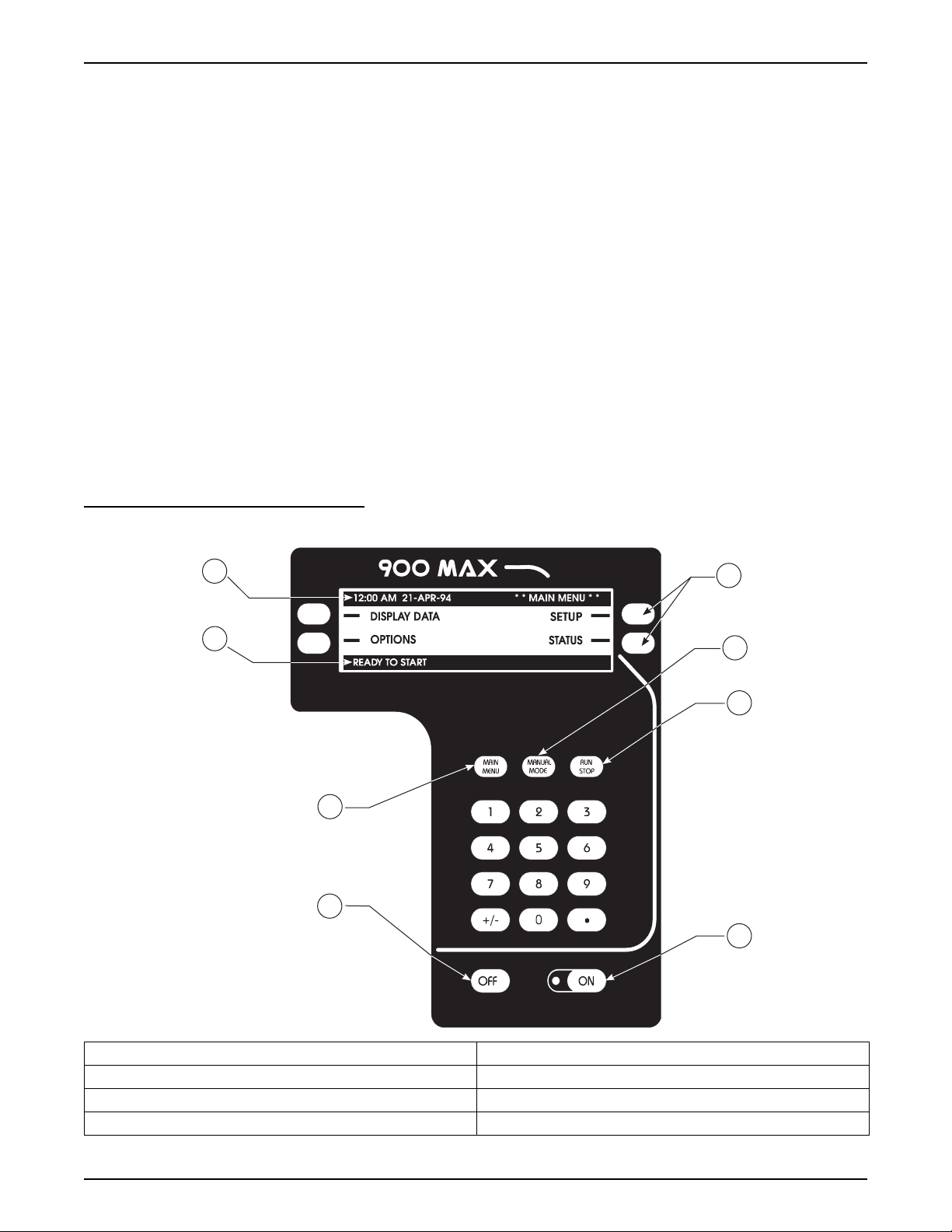
1.2 Front Panel
The front panel (Figure 1) of the sampler consists of the keypad, liquid crystal
display, and the internal case humidity indicator.
Figure 1 Front Panel
8
7
1
2
3
6
5
4
1. Soft Keys 5. Power OFF Key
2. Manual Mode Key 6. Main Menu Key
3. Run/Stop Key 7. Status Bar
4. Power ON Key 8. Menu Bar
Page 15
8990int.fm Introduction
Page 18

Section 1
1.2.1 Keypad Description
The keypad includes the numeric keypad, soft keys, and function keys.
Numeric Keypad
The numeric keypad consists digits 0 through 9, a +/- key, and a decimal key.
“Soft” Keys
Soft keys are blank, white keys located to the left and right of the display. If no
function is shown for a specific key, that key is not currently active. The soft
key labels appear on the display and indicates (with a straight line) the proper
soft key to push for that action.
In some cases during a programming step an item from a list needs to be
selected. The soft keys on the right side of the display will change to display
UP and DOWN arrows. Scroll through the list of choices.
Power ON/OFF Key
To turn the instrument on, press the
on, a green light located next to the
sampler power is turned on. To turn the instrument off, press the
ON key. When the instrument is turned
ON key flashes to indicate that the
OFF key.
Function Keys
Three white function keys (Tab l e 1 ) are located just above the numeric keypad
re used often while operating the sampler. These functions are dedicated
keys to allow quick access.
Table 1Function Key Descriptions
Function Key Description
Main Menu
This is the starting point to get to any other point in the program. Press the Main Menu key at any time
during programming to return to the Main Menu Screen. The current action is cancelled if changes are not
yet accepted.
Manual Mode
Manually controls the operation of the sample pump and the distributor arm.
ADVANCED DISTRIBUTOR soft key: Moves the distributor arm to the user selected bottle. Used to verify the
operation of the distributor or when repositioning the arm if it was moved by hand.
GRAB SAMPLE soft key: Takes a sample in the same manner as when a program is running. Includes all
pre-rinses and sample retries, if programmed.
PUMP OPERATION soft key: Allows manual control of the pump in both forward and reverse directions. Once
started, the pump is stopped by pressing any key.
Run/Stop
Runs (or resumes) a program and stops a currently running program.
1.2.2 Liquid Crystal Display
The liquid crystal display (LCD) works in conjunction with the four soft keys.
When a soft key changes function, the display shows the new function.
Page 16
Front Panel
Menu Bar
The Menu Bar appears in a black band on the top edge of the display.
The upper left corner of the menu bar shows the time and date. The upper
right corner shows the name of the current menu (Figure 1).
8990int.fm
Page 19

Status Bar
The Status Bar appears along the bottom edge of the display.
The appearance of the status bar changes depending upon the
function performed (Figure 1). The lower left corner of the Status Bar
indicates whether a program is Complete, Running, Halted, or Ready To Start.
If it is not needed during a programming step, it disappears.
The lower right corner displays system alarm conditions, such as low memory
battery, jammed distributor etc. For a list of possible alarms refer to
section 6.4 on page 89. The status bar also lists the valid choices when
entering certain programming information.
1.2.3 Internal Humidity Indicator
The round window of the internal case humidity indicator (Cat. No. 2660)
turns pink when the internal case humidity exceeds 60 percent.
The sampler is equipped with an internal desiccant module (Cat. No. 8849) to
absorb any humidity that may have been trapped in the case during final
assembly. Under normal operating conditions, this desiccant provides longterm protection against condensed moisture inside the case.
Replacement of the internal desiccant module is only necessary if the
indicator turns pink. (Refer to section 7.10 on page 103 for details on
replacing the internal desiccant.)
Section 1
Figure 2 Humidity Indicator
Internal Humidity
Replace
Desiccant
When
Pink
Page 17
8990int.fm Front Panel
Page 20
Section 1
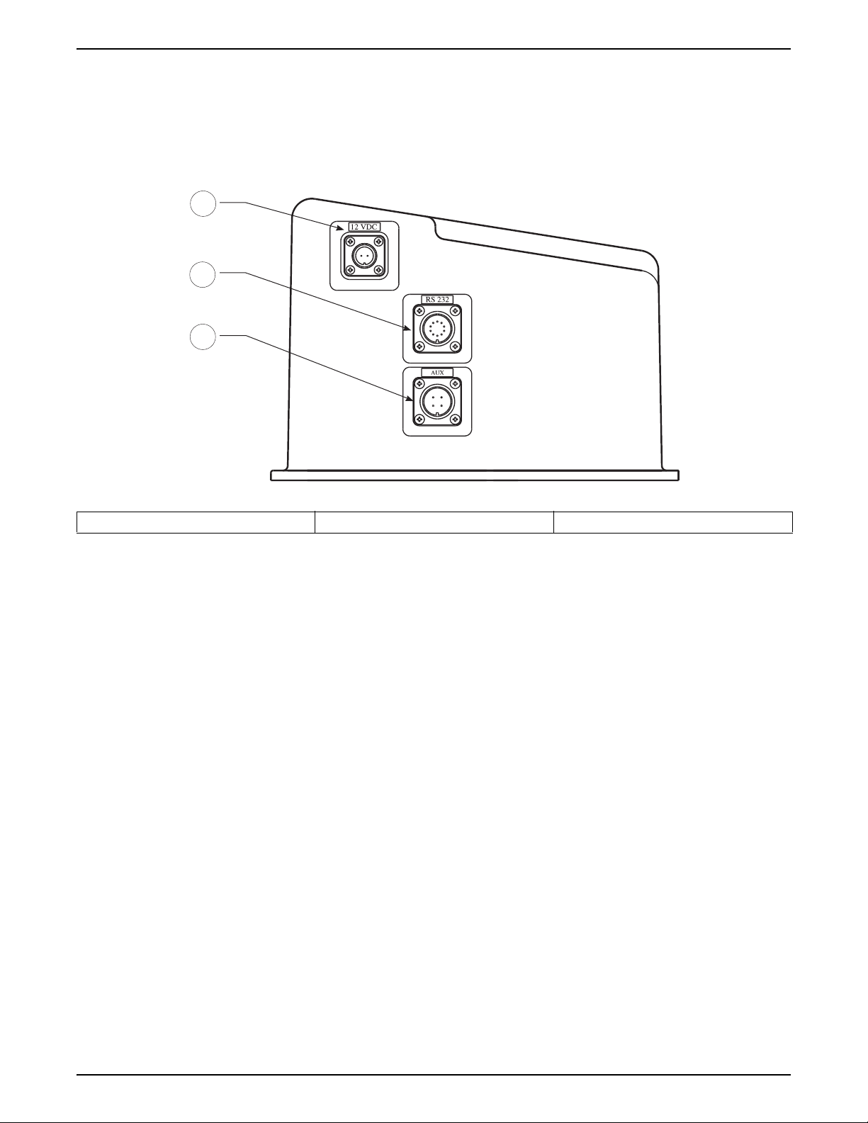
1.3 Interface Connectors
1
2
3
Interface connectors are located on the left side of the controller housing. An
optional weather tight terminal box located on the back of the sampler
provides conduit termination for all input/output lines.
1. 12 V dc 2. RS232 3. Auxiliary
The sampler comes standard with two interface receptacles.
• 12 V dc (Power Input)
• Auxiliary (Multi-purpose input/output port)
• RS232 (Serial communications port)
• Thermal (Control port for heating and cooling system)
In addition, the sampler can be used with a wide variety of optional devices:
• Level and Flow Monitoring
(Sensors)
• pH/ORP • 4–20 mA Current Loop Output
• Conductivity • Modem
• Dissolved Oxygen • Rain Gauge
• Temperature
Three additional analog inputs of
4–20 mA or -4.0 V dc to +4.0 V dc
1.3.1 Receptacle Caps
Page 18
Interface Connectors
Interface receptacles are covered with push-on receptacle caps. These caps
protect the connector pins from dirt and moisture and should be attached to
any receptacle not in use.
8990int.fm
Page 21
1.4 Principle of Operation
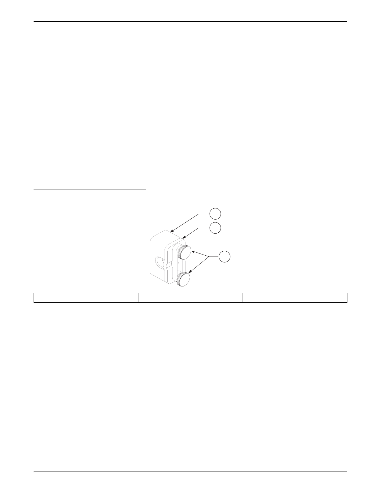
1.4.1 Liquid Sensing
The sampler is designed for indoor, permanent installation. All controls are
located on the front panel. Capped, watertight connectors for interfacing to
external devices are located along the left side of the controller.
The sampler uses a liquid sensing system to detect the absence or presence
of liquid at the peristaltic pump intake. The liquid sensor (Figure 3) is located
on the front of the control housing.
The liquid sensing system provides three primary benefits:
• Accurate, repeatable sample volumes
• Intake tube prerinse
• Sample retry
Figure 3 Liquid Sensor
Section 1
1
2
3
1. Sensor Body 2. Sensor Cover 3. Knobs (turn to remove)
Accurate, Repeatable Sample Volumes
The liquid sensor detects the presence and velocity of the incoming sample.
This information allows the sampler to automatically dispense the correct
amount of liquid into the sample bottle.
The liquid sensing system allows the sampler to deliver repeatable sample
volumes even with changing suction lifts. Each time the peristaltic pump pulls
a sample, the microprocessor determines the time required for liquid to travel
to the liquid sensor. If the suction lift increases due to a drop in level at the
sample source, the time required for liquid to reach the sensor will increase.
The microprocessor automatically compensates for this change by allowing
the peristaltic pump to deliver sample liquid for a corresponding longer period
of time. Conversely, if suction lift decreases due to an increase in level at the
sample source, the time required for liquid to the sensor will decrease. Again,
the microprocessor automatically compensates for this change by decreasing
the sample delivery time.
Page 19
8990int.fm Principle of Operation
Page 22

Section 1
Intake Tube Pre-Rinse
The liquid sensor also rinses the intake tubing with the liquid from the sample
source before taking each sample.
Upon sample initiation, the pump purges the intake line. The pump then
reverses, pulling liquid through the tubing, until it reaches the liquid sensor.
When the sensor detects liquid, the pump purges back to the source, and
then draws a sample. After the desired sample is collected, the pump purges
the intake line and awaits the next sample cycle. The sampler can be
programmed for up to 3 rinses before each sample.
Sample Retry
The liquid sensing system permits the sampler to repeat a collection cycle if a
sample is not obtained during the regular cycle.
The intake line length is user-programmed into the sampler memory. For a
line length of 3 to 99 feet, the sampler has a built-in “look up” table that
detects the maximum time required for liquid to reach the sensor. If liquid
does not reach the sensor within the defined time period, the pump will
automatically purge the intake line and initiate another sample cycle. The
sampler may be programmed for up to three repeated attempts. If a sample is
not obtained, the sampler retains in memory the time, date and reason for the
missed sample.
Page 20
Principle of Operation
8990int.fm
Page 23

INSTALLATION
DANGER
Some of the following manual sections contain information in the form of warnings, cautions and notes
that require special attention. Read and follow these instructions carefully to avoid personal injury and
damage to the instrument. Only personnel qualified to do so, should conduct the installation/maintenance
tasks described in this portion of the manual.
DANGER
Certains des chapitres suivants de ce mode d’emploi contiennent des informations sous la forme
d’avertissements, messages de prudence et notes qui demandent une attention particulière. Lire et suivre
ces instructions attentivement pour éviter les risques de blessures des personnes et de détérioration de
l’appareil. Les tâches d’installation et d’entretien décrites dans cette partie du mode d’emploi doivent être
seulement effectuées par le personnel qualifié pour le faire.
PELIGRO
Algunos de los capítulos del manual que presentamos contienen información muy importante en forma de
alertas, notas y precauciones a tomar. Lea y siga cuidadosamente estas instrucciones a fin de evitar
accidentes personales y daños al instrumento. Las tareas de instalación y mantenimiento descritas en la
presente sección deberán ser efectuadas únicamente por personas debidamente cualificadas.
GEFAHR
Einige der folgenden Abschnitte dieses Handbuchs enthalten Informationen in Form von Warnungen,
Vorsichtsmaßnahmen oder Anmerkungen, die besonders beachtet werden müssen. Lesen und befolgen
Sie diese Instruktionen aufmerksam, um Verletzungen von Personen oder Schäden am Gerät zu
vermeiden. In diesem Abschnitt beschriebene Installations- und Wartungsaufgaben dürfen nur von
qualifiziertem Personal durchgeführt werden.
PERICOLO
Alcune parti di questo manuale contengono informazioni sotto forma d’avvertimenti, di precauzioni e di
osservazioni le quali richiedono una particolare attenzione. La preghiamo di leggere attentivamente e di
rispettare quelle istruzioni per evitare ogni ferita corporale e danneggiamento della macchina. Solo gli
operatori qualificati per l’uso di questa macchina sono autorizzati ad effettuare le operazioni di
manutenzione descritte in questa parte del manuale.
Page 21
8990i_stop.fm INSTALLATION
Page 24

Visit http: //www.hach.com
Page 25
Section 2 Installation
DANGER
This instrument should be
installed by qualified technical
personnel to ensure adherence to
all applicable electrical codes.
DANGER
Cet appareil doit être installé par du personnel technique qualifié, afin d'assurer
le respect de toutes les normes applicables d'électricité.
2.1 Unpacking the Instrument
Remove the sampler from the shipping carton and inspect it for any damage.
Contact Hach Customer Service at 1-800-227-4224 if any items are missing
or damaged.
2.2 Selecting the Installation Site
DANGER
This product is not designed for
hazardous locations where
combustible environments may
exist.
DANGER
Ce produit n'est pas conçu pour des endroits dangereux dans lesquels il peut
exister des environnements combustibles.
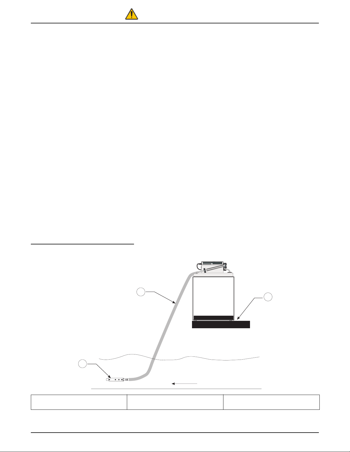
See Figure 4 and follow the simple guidelines below to allow complete
drainage of the intake line and prevent cross-contamination between samples.
• Install the sampler as close to the sample source as site conditions
permit. This will increase pump tube life and optimize overall sampler
performance.
• Install the sampler above the sample source, with the intake tubing
sloping downward to the sample.
• Make sure that the intake tubing is free of kinks or loops.
Figure 4 Setting Up the Instrument
3
1
2
FLOW
1. Slope tubing down to source (no
loops, kinks, or excessive tubing)
8990hrd.fm Installation
2. Place sampler on a level surface. 3. Locate strainer in an area of
turbulent and well mixed flow.
Page 23
Page 26
Section 2
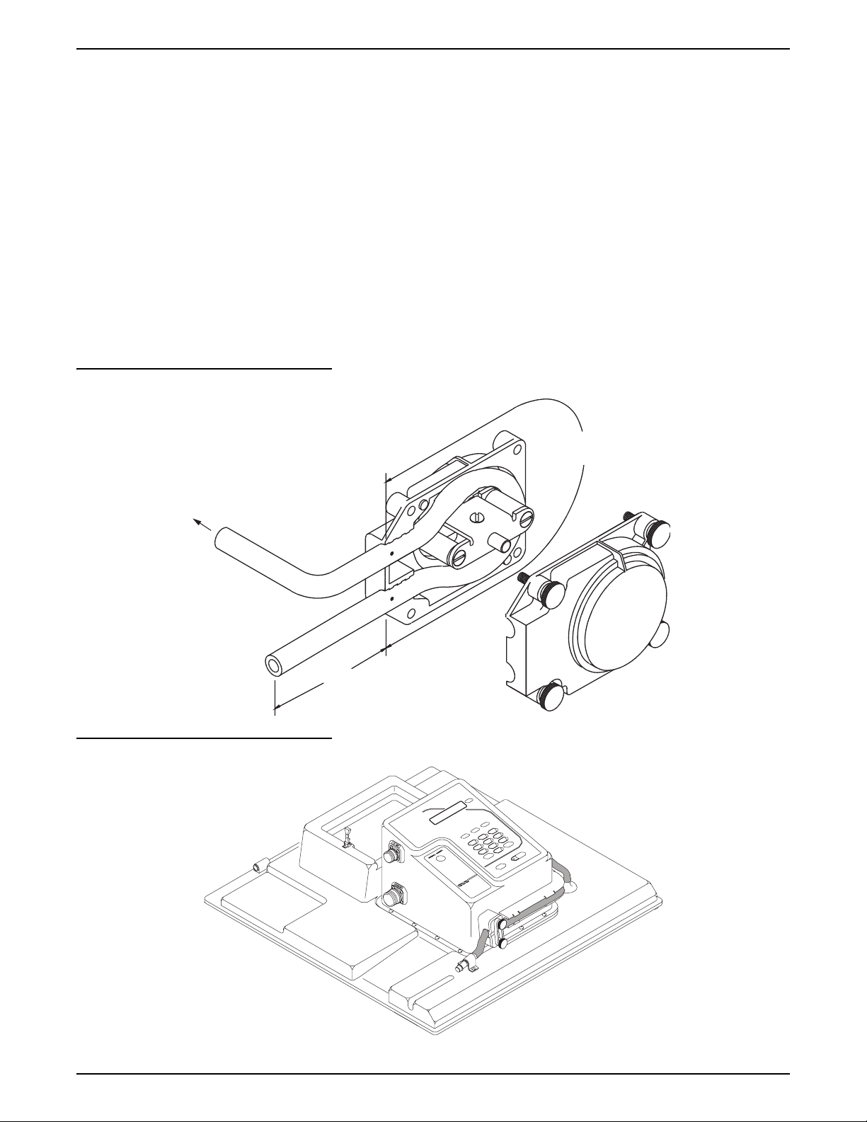
2.3 Installing the Pump Tube in the Sensor Body
1. Remove the four screws on the pump cover (Figure 5).
Note: Do not stretch the tubing in
the sensor body, as this could affect
the ability of the sensor to detect
liquid through the pump tubing.
2. Remove the front cover of the pump housing. Remove the tubing. Locate
the black dots on the tubing. The end of the tube that extends farthest
beyond the black dot attaches to the stainless steel tubing connector.
3. Install the pump tube in the pump housing so the black dots are visible
just outside the pump body.
Note: Use the proper length of
silicone tubing in the pump body. An
improper length can reduce the life
of the tubing and pump rollers. Refer
to Figure 5 for the correct length.
Figure 5 Pump Tube Loading
To Intake Tubing Connector
4. After inserting the new pump tube as shown, reinstall the front cover and
secure it with the four screws until finger tight.
5. Make sure that the tubing extends through the liquid sensor and out of the
controller as shown in Figure 6.
11 5/8 in.
(Tubing in Pump)
5 3/4 in. to Sample Fitting
Figure 6 Installing Pump Tube Through the Sensor Body
Page 24
Installing the Pump Tube in the Sensor Body
8990hrd.fm
Page 27
2.3.1 Attaching the Intake Line
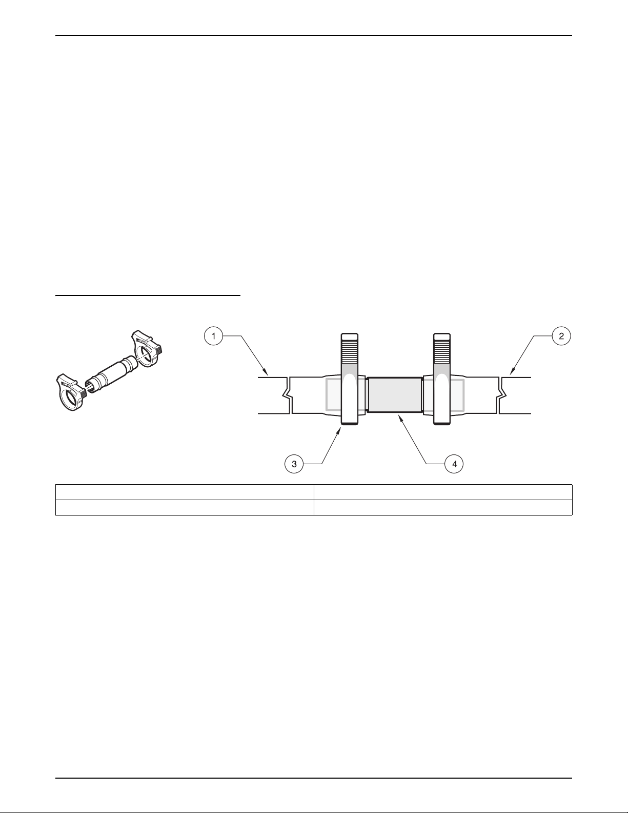
2.3.1.1 Attaching the Vinyl Tubing
The connection kit (Cat. No. 2248) contains two identical assemblies, one for
connecting vinyl tubing to the tubing attached to the sampler, and the other for
connecting the vinyl tubing to an intake strainer or remote pump. The kit
contains four hose clamps and two stainless-steel tubing connectors.
1. Push one end of the tubing connector into the vinyl tubing attached to the
controller until the tubing abuts the shoulder of the tubing connector.
Secure with a tubing clamp (Figure 7).
2. Push the other end of the tubing connector into the vinyl tubing until the
tubing abuts the shoulder of the tubing connector and secure with a
tubing clamp (Figure 7).
3. Repeat Step 1 and Step 2 for the fitting that connects the vinyl tubing to
an intake strainer or a remote pump.
Figure 7 3/8” Vinyl Tubing Connector
Section 2
1. Vinyl tubing to controller 3. Tubing clamp (2 required)
2. Vinyl tubing to strainer or pump. 4. Stainless-steel tubing connector
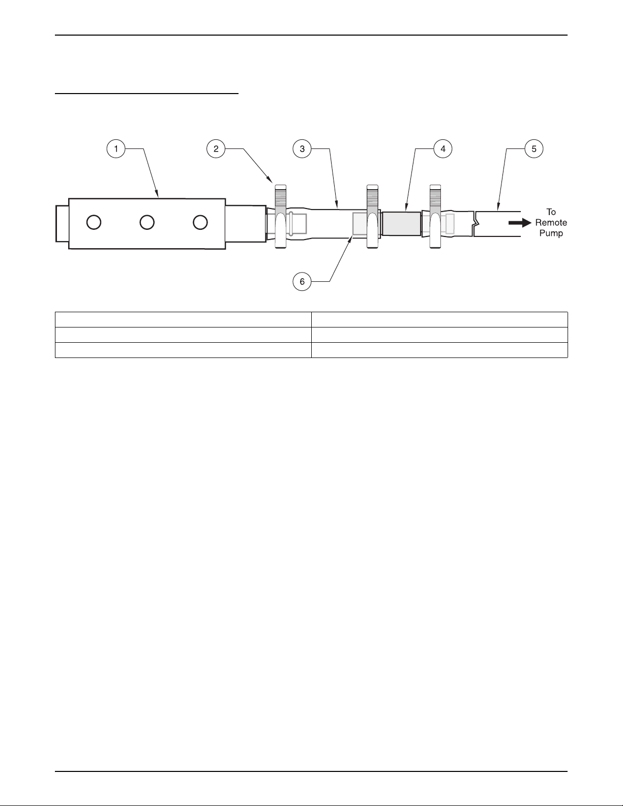
2.3.1.2 Attaching the Teflon®-Lined Tubing
The Connection Kit for Teflon-lined Tubing (Cat. No. 2186) contains two
identical assemblies, one for connecting the Teflon-lined tubing to the
stainless steel tubing connector and the other for connecting the Teflon-lined
tubing to the intake strainer. The kit contains six clamps, two lengths of
silicone tubing, and two stainless-steel barbed fittings.
To connect the Teflon-lined tubing follow the instructions and Figure 8 below:
1. Place the Teflon-lined tubing over the tubing connector nipple until it abuts
the shoulder of the tubing connector and secure with a tubing clamp.
2. Place one end of the silicone tubing over the wide end of the tubing
connector and secure with a tubing clamp.
3. Slide a second tubing clamp over the other end of the silicone tubing.
Push the silicone tubing over the stainless-steel fitting on the intake
strainer and tighten the tubing clamp.
Page 25
8990hrd.fm Installing the Pump Tube in the Sensor Body
Page 28
Section 2
4. Repeat the procedure for the fitting that connects the Teflon-lined tubing
to the silicone pump tubing.
Figure 8
1. Intake strainer 4. Stainless-steel tubing connector
2. Tubing clamp (3 required) 5. Teflon-lined intake tubing
3. Two-inch piece of silicone tubing 6. Wide end of stainless steel tubing connector
3
/8″ ID Teflon-lined Tubing Attached to Intake Strainer and Tubing Connector
2.3.2 Setting Up the Intake Line and Strainer
Note: If site conditions do not permit
the intake to slope downward from
the sampler to the sample source,
disable the liquid sensors by
calibrating the sample volume using
the Timed Calibrate method when
programming the sampler.
For each sampling location, the intake line should be as short as practical,
and be free of any sharp bends, coils, or loops. Install the intake line with a
downward slope from the sampler to the sample source because:
• This will ensure the complete drainage of the intake line when it is
air-purged before and after each sample, and will help to prevent
cross-contamination of the individual samples.
• Complete drainage is important in freezing conditions, as any liquid slugs
that remain could freeze and plug the line and possibly damage the
sampler.
Note: Vertical lift should not exceed
27 ft. If the site requires more lift,
you may purchase the Remote
Pump Option. The remote pump
option is factory installed. Any
remote pump installed outside the
factory will void the warranty.
Place the sample intake and strainer in the mainstream of the sampling
source, in an area of turbulent and well mixed flow.
Also, you must account for the vertical location of the intake. A position too
near the surface may yield excess lighter materials, while a position too near
the bottom may yield excess heavy materials. The constituents of interest
must be considered when positioning the intake strainer.
2.4 Choosing Bottle and Retainer Configurations
A broad range of bottle configurations are available for the Sigma 900 MAX
Refrigerated Sampler.
Page 26
Choosing Bottle and Retainer Configurations
8990hrd.fm
Page 29
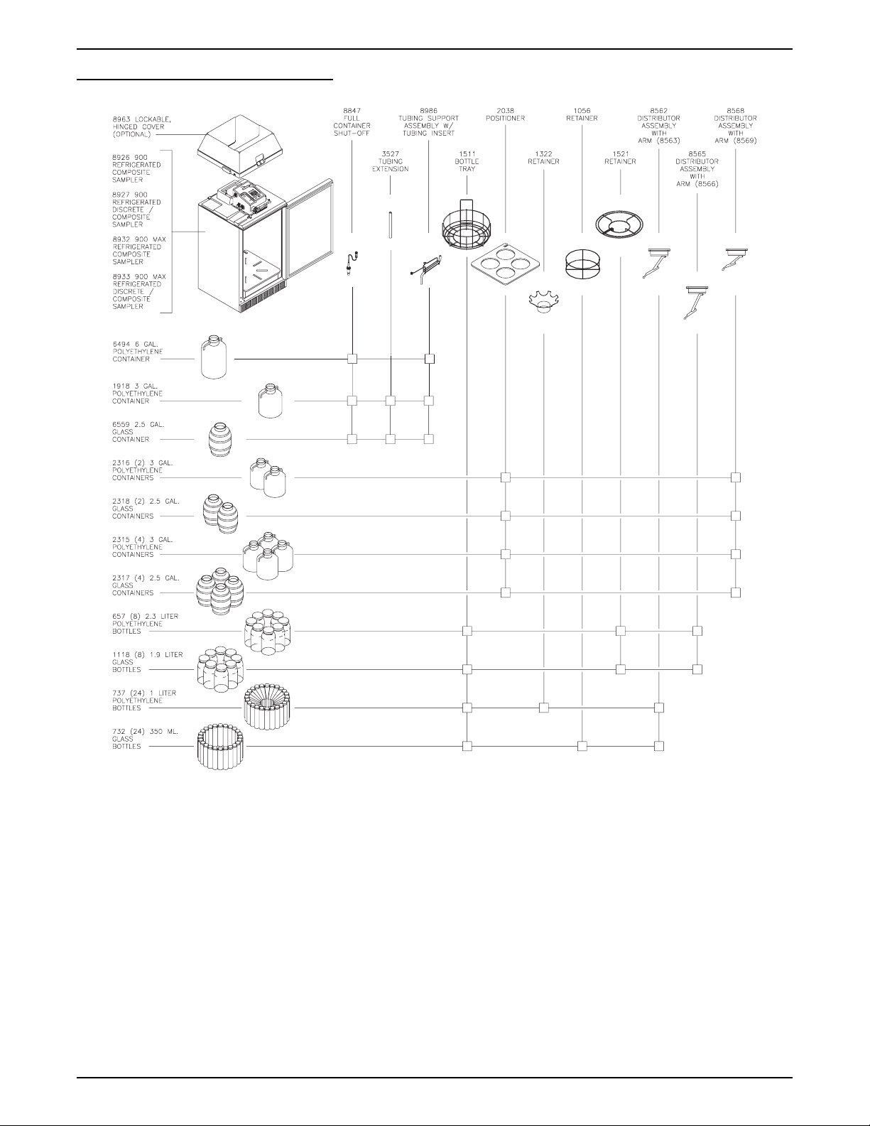
Figure 9 Bottle Configurations
Section 2
2.5 Setting Up the Bottles
2.5.1 One-Bottle Sampling
For single bottle composite sampling, install the Full Bottle Shut-off (refer to
Section 2.7 on page 31) and place the bottle in the center of the refrigerator
(Figure 15 on page 31). The Full Bottle Shut-off positions the sample tubing
over the bottle mouth.
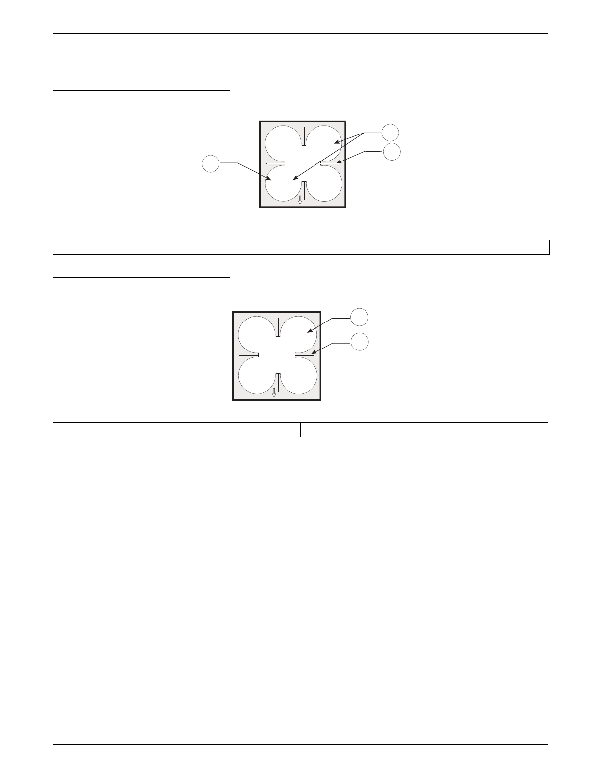
2.5.2 Two- and Four-bottle Sampling
For two-bottle sampling, install the distributor (refer to Section 2.6.1 on
page 30) and place the bottles in the Bottle #1 and Bottle #2 positions in the
tray as shown in Figure 10.
Page 27
8990hrd.fm Setting Up the Bottles
Page 30
Section 2
For four-bottle sampling, install the distributor and place all four bottles in the
tray as shown in Figure 11.
Figure 10 Two-bottle Locations
2
2
1
3
1
Front
1. Single Bottle Location 2. Two Bottle Location 3. Slots for Wire From Bottle Tray (8 or 24 bottle)
Figure 11 Four-bottle Locations
1
2
1
1. 1, 2, or 4 Bottle Locations 2. Slot for Wire From Bottle Tray (8 or 24 bottles)
2.5.3 Eight-, 12-, or 24-bottle Sampling
For eight-, 12- or 24-bottle sets, install the distributor (refer to section 2.6.1 on
page 30). Place the bottles in the tray and install the proper bottle retainer
(Figure 12).
Bottle #1 is the first bottle clockwise (looking down on the tray) from the right
side of the tray. Bottle #1 is located on the inside of each bottle tray for all
multiple bottle sets (Figure 12).
Front
3
4
2
Page 28
Setting Up the Bottles
8990hrd.fm
Page 31

Figure 12 Eight-, 12-, or 24-bottle Configuration
1
2
3
1. Distributor 2. Retainer 3. Bottles and Bottle Tray
Section 2
2.6 Installing the Distributor (Multiple Bottle Operation)
Note: Make sure the sampler is
powered off before removing or
installing the distributor.
For multiple bottle sampling, a motorized arm (Distributor) is provided to
automatically position the sample tube over the proper bottle. The
microprocessor-controlled distributor arm can automatically locate two, four,
eight, 12, or 24 discrete bottles.
To install the distributor:
1. Locate the two slots along one edge of the distributor assembly base
plate (Figure 14). Slide the distributor assembly, slots first, under the
shoulder screws located on the top inside surface of the controller
section.
2. When fully seated, hand tighten the knurled thumbscrew to hold the
distributor in place.
3. To ensure the arm has sufficient freedom of movement, hand-rotate the
arm to the opposite end of the Arm Stop.
4. Install the silicone distributor tubing to the sample fitting on the top
underside surface of the controller housing.
Note: Use care not to force the arm past the Arm Stop clip. The Arm Stop keeps the
arm from being rotated more than 360 degrees and keeps the distributor tubing
from kinking.
The distributor tubing should be installed so that the end of the tubing extends
out of the nozzle end of the distributor arm no more than
not let the tubing extend more than
8990hrd.fm Installing the Distributor (Multiple Bottle Operation)
1
/8 in. past the nozzle end of the arm.
1
/8 in. (Figure 13). Do
Page 29
Page 32

Section 2
2.6.1 Distributor Arm Alignment
1. Program the sampler for 24-bottle operation.
2. Press
Bottle #1 position.
3. Place the arm on the distributor shaft and align the rib on the inside wall of
the control housing skirt.
4. Secure the arm to the shaft by tightening the
located on the distributor arm.
Figure 13 Distributor Tubing in Arm
START PROGRAM to set the distributor shaft to the
1
/8 in. hex-head screw,
1
2
1. Distributor Shaft 2. Nozzle End (1/8 in. max)
Figure 14 Distributor Installation
2
3
1
1. Refrigerator 2. Distributor Assembly 3. Distributor Arm
Page 30
Installing the Distributor (Multiple Bottle Operation)
8990hrd.fm
Page 33

Section 2
2.7 Installing the Full-Bottle Shut-Off Device (Single Bottle Operation)
1. Install the rubber grommet into the hole provided in the cap of the
composite bottle.
2. Slide the Full Bottle Shut-Off, float first, into the bottle through the center
of the grommet.
3. Insert the Full Bottle Shut-Off connector into the receptacle (Figure 15)
and securely tighten.
Figure 15 Full Bottle Shut-off Installation
2
1
1. Full Bottle Shut-off 2. Refrigerator
2.8 Power Connections
Note: Install the sampler on its own
circuit to ensure a continuous,
stable source of power.
Use the ac power cords to apply ac power to the controller and
the refrigerator.
The sampler controller operates on a 12 V dc which is supplied by a built-in
ac/dc power converter. The power supply is permanently sealed in the
compartment located behind the transition plate. An ac line fuse is located on
the left side of the controller.
An optional power backup assembly is located on top of the ac power supply.
The ac power backup is designed to power the pump and controller only. Pull
the rubber hold-downs up and over the clips at each end of the ac Power
Backup to hold it in place.
The short, 2-pin cable on the power supply (or battery) connects to the
controller receptacle labeled 12 V dc.
Page 31
8990hrd.fm Installing the Full-Bottle Shut-Off Device (Single Bottle Operation)
Page 34

Section 2
Important: Whenever electricity is present, there is a possibility of electrical
shock. Before connecting the sampler to an ac power source, the following
safety precautions should be taken:
• Check the power source to make sure that it satisfies the ac power
requirements of the sampler.
• Make sure that all electrical installations and connections are in
accordance with national and local electrical codes.
• Before performing any maintenance, disconnect the sampler from the
power source.
• Do not attempt to make any connection or otherwise handle the electrical
components of the sampler when connected to ac line power if the
immediate area is wet, or if hands or clothing are wet.
• If the circuit breaker or fuse in the ac power source is tripped, determine
the cause before restoring power to the sampler.
• Make sure the power circuit is grounded and protected with a Ground
Fault Interrupter (GFI).
2.9 Auxiliary Receptacle Pin Identification
Pin A/White (12 V dc) Powers an external device or flow meter. Must be used in conjunction with Pin B (ground).
Pin B/Blue (Ground) Connected to dc ground and is isolated from the earth ground found in the ac power line.
With the sampler in Flow Proportional mode and connected to an external flow meter, a 5 to
12 V dc input pulse lasting at least 25 milliseconds will cause the sampler to decrement one
Pin C/Yellow (Pulse Input)
Pin D/Black
(Liquid Level Actuator/
Auxiliary Control Input)
count. The 12 V dc line found on Pin A can be used directly with a simple contact closure to
Pin C or an external 5 to 12 V dc pulse may be applied providing the ground side of the
external signal is connected to the sampler ground at Pin B. This count is actuated at the
beginning of the input signal (the leading edge of the pulse).
This line is held at 5 V dc inside the sampler. When shorted to ground (Pin B), a signal is sent
to the microprocessor inside the sampler causing it to “wake up” and begin or resume its
sampling program. It can be used in conjunction with a simple level float to actuate the
sampler when liquid is present or to take over after a second sampler has finished its
program. It may also be used with any device (such as a pH meter) that produces a dry
contact output to control the sampler in response to some user-defined condition (i.e. high or
low pH); must be used in conjunction with Pin B.
Pin E/Red (Special Output) Normally at 0 V dc, this line goes to 12 V dc upon any of the selected events described in.
Normally an open circuit, this line switches to ground for 90 seconds at the conclusion of the
Pin F/Green
(Program Complete Output)
Page 32
Auxiliary Receptacle Pin Identification
sampling program. Used to “wake up” another sampler to take over sampling or to signal an
operator or data logger upon the completion of the sampling program. This pin is also used to
signal the bottle full condition in a single bottle/continuous mode, and will transmit the bottle #
to an 950 Flow Meter if the program complete signal is disabled.
8990hrd.fm
Page 35

2.9.1 Splitter Interface
Figure 16 Splitter Interface
Section 2
Use the Splitter Interface (Cat. No. 939) when more than one signal is needed
simultaneously. Connecting the interface to the 6-pin connector on the
sampler provides three additional connectors. Two or more interfaces may be
connected in series to allow for additional connections.
Page 33
8990hrd.fm Auxiliary Receptacle Pin Identification
Page 36

Visit http: //www.hach.com
Page 37

OPERATION
DANGER
Handling chemical samples, standards, and reagents can be dangerous. Review the necessary Material
Safety Data Sheets and become familiar with all safety procedures before handling any chemicals.
DANGER
La manipulation des échantillons chimiques, étalons et réactifs peut être dangereuse. Lire les Fiches de
Données de Sécurité des Produits (FDSP) et se familiariser avec toutes les procédures de sécurité avant
de manipuler tous les produits chimiques.
PELIGRO
La manipulación de muestras químicas, estándares y reactivos puede ser peligrosa. Revise las fichas
de seguridad de materiales y familiarícese con los procedimientos de seguridad antes de manipular
productos químicos.
GEFAHR
Das Arbeiten mit chemischen Proben, Standards und Reagenzien ist mit Gefahren verbunden. Es wird dem
Benutzer dieser Produkte empfohlen, sich vor der Arbeit mit sicheren Verfahrensweisen und dem richtigen
Gebrauch der Chemikalien vertraut zu machen und alle entsprechenden Materialsicherheitsdatenblätter
aufmerksam zu lesen.
PERICOLO
La manipolazione di campioni, standard e reattivi chimici può essere pericolosa. La preghiamo di prendere
conoscenza delle Schede Techniche necessarie legate alla Sicurezza dei Materiali e di abituarsi con tutte
le procedure di sicurezza prima di manipolare ogni prodotto chimico.
Page 35
8990o_stop.fm OPERATION
Page 38

Visit http: //www.hach.com
Page 39

Section 3 Basic Programming Setup
3.1 Initial Power-Up of Sampler
After pressing the ON key, the sampler performs a complete diagnostic test
and displays the menu shown when the unit was last turned off. Set the
instrument programming features when the Main Menu is displayed. The Main
Menu is the starting point for all programming operations. The Main Menu
offers four choices:
• Setup—Basic and Advanced Sampling programming
• Status—Lists all current sampling status, power supply voltage, and
values of any data channels that are enabled.
• Display Data—Shows graphs and tables of logged data
(Displaying Data on page 113)
• Options—Optional Device Programming
Setup and Option functions lead to sub-menus and will configure the basic
and advanced features of the sampler. Refer to the Quick Start Guides on
page 105. The Display Data and Status Menus lead to sub-menus and will
provide information only. Press
enabled logging (flow, pH, temp., etc.)
STATUS to display any data channels that have
11:00 AM 21 - APR - 01 * MAIN MENU*
READY TO START
3.2 Basic Programming Setup
Basic programming setup must be performed, step-by-step and in its entirety,
after the instrument is installed. Refer to the Quick Start Guides on page 105
for more information. The basic program setup will modify the following items:
• Bottles • Intake Tubing
• Program Lock • Program Delay
• Sample Collection • Sample Distribution
• Liquid Sensor • Sample Volume
• Intake Rinses • Sample Retries
• Site ID
DISPLAY DATA SETUP
OPTIONS STATUS
In addition, several advanced sampling features are found on a sub-menu
called Advanced Sampling. Refer to section 3.3 on page 49 for Advanced
Sampling Basic Programming Setup.
Page 37
8990startup.fm Basic Programming Setup
Page 40

Section 3
To make changes to the program entries after the basic programming setup,
press
MAIN MENU and select SETUP>MODIFY SELECTED ITEMS and highlight
the program entry using the
UP and DOWN keys.
To review all information in the Setup and Option menus without worrying
about accidentally changing the information, use the Review All Items function
to verify that the program is properly set up. For more information on this
function refer to Review All Items on page 113.
1. Press
11:00 AM 21 - APR - 01 * MAIN MENU*
READY TO START
2. From the Main Menu select
11:00 AM 21 - APR - 01 * MAIN MENU*
READY TO START
3. Press
SETUP from the Main Menu to prepare the instrument for use.
DISPLAY DATA SETUP
OPTIONS STATUS
SETUP>MODIFY ALL ITEMS.
MODIFY
ALL ITEMS
REVIEW ALL
ITEMS
ACCEPT to begin setting up the bottles.
SELECTED ITEMS
MODIFY
Step 1 - Bottles
1-A. Enter the total number of sample bottles in the refrigeration
compartment, using the numeric keypad.
11:00 AM 21 - APR - 01 BOTTLES
ACCEPT NUMBER OF BOTTLES:
—
BACKUP
ENTER: 1, 2, 4, 8, 12, OR 24
Note: The bottles may be installed directly in the refrigeration compartment or in the
removable bottle tray when using sets greater than four bottles.
CLEAR
ENTRY
1-B. Press ACCEPT to continue and move to the Bottle Volume menu.
Page 38
Basic Programming Setup
8990startup.fm
Page 41

Section 3
1-C. Enter the bottle volume using the numeric keypad and select gallons or
milliliters using the
11:00 AM 21 - APR - 01 BOTTLES
CHANGE UNITS key.
Step 2 - Intake Tubing
ACCEPT
BACKUP
1-D. Press
11:00 AM 21 - APR - 01 INTAKE TUBING
ACCEPT and continue to Intake Tubing.
ACCEPT
BACKUP
BOTTLE VOLUME
— —
ENTER: 0.500—99.90
INTAKE TUBE LENGTH:
_____
ENTER: 3—99
CHANGE
UNITS
CLEAR
ENTRY
CHANGE
UNITS
CLEAR
ENTRY
2-A. Enter the intake tube length attached to the sampler, using the numeric
keypad. Length values from 100 to 3000 cm (3 to 99 ft) are valid.
Change the measurement unit using the
Note: Intake tube length affects sample volume accuracy, cut the tubing to the nearest
whole foot. Avoid excessively long tubing runs. Doubling the intake tubing length
can quadruple the pump tubing wear if intake rinses or sample retries are
enabled. Always locate the sampler close to the sample liquid source to minimize
tubing, pump, motor, and gearbox maintenance.
CHANGE UNITS key.
Step 3 - Program Lock
Note: The program lock password is
configured at the factory as “9000”
and cannot be changed.
2-B. Press ACCEPT to move to the Intake Tube Type menu.
2-C. Select the type of intake tube (
using the
2-D. Press
CHANGE UNITS key.
ACCEPT to select the intake tube type and continue with Program
3
/8 in. Vinyl, ¼ in. Vinyl, 3/8 in. Teflon®)
Lock.
Enabling the Program Lock will provide a protective “password” which will
keep unauthorized personnel from tampering with the instrument keypad.
3-A. Enable or Disable Program Lock using the
Note: When program lock is enabled and a user attempts to make a change in the
program, a screen will ask the operator to enter the password. The operator must
enter 9000 and press ACCEPT.
CHANGE CHOICE key.
3-B. Press ACCEPT to continue the basic program setup and continue with
Program Delay.
Page 39
8990startup.fm Basic Programming Setup
Page 42

Section 3
Step 4 - Program Delay
Note: If both Setpoint Sampling and
Program Delay are enabled, the
program delay is evaluated first,
prior to any checking for
setpoint conditions.
4-A. Enable or Disable Program Delay using the CHANGE CHOICE key.
4-B. After enabling the program delay, enter the time and day of week that
11:00 AM 21 - APR - 01 PROGRAM DELAY
4-C. Press
Step 5 - Sample Collection
5-A. Select the type of sample collection; Time Proportional,
Enabling the Program Delay will cause the sampling program to delay
starting until a user specified time and day of week are programmed.
the program will begin. Use the soft keys to change the day of week as
well as the AM/PM indicator.
ACCEPT
CLEAR
ENTRY
ACCEPT to continue with Sample Collection.
START PROGRAM:
00:00 AM MON
(USE THE NUMERIC KEYPAD)
CHANGE
AM/PM
CLEAR
DAY
Flow- Proportional Constant Volume, Variable Time (CVVT), or
Flow-Proportional Constant Time, Variable Volume (CTVV).
11:00 AM 21 - APR - 01 SAMPLE COLLECTION
Timed-Proportional Sampling Intervals
When the program starts, a sample is taken immediately or delayed until after
the first interval has elapsed. Select either, Take First Sample Immediately or
After the First Interval.
Timed-Proportional samples are taken each time a user defined time interval
has elapsed. Samples can be continually taken at that interval until the
completion of the program.
11:00 AM 21 - APR - 01 SAMPLE COLLECTION
ACCEPT
BACKUP
CHOICES: TIMED, FLOW PROPORTIONAL
a. From the Sample Collection menu, press
SAMPLE COLLECTION
_______________
CHANGE CHOICE until
Timed Proportional is displayed. Press ACCEPT to continue.
ACCEPT
BACKUP
CHOICES: TIMED, FLOW PROPORTIONAL
SAMPLE COLLECTION
TIMED PROPORTIONAL
CHANGE
CHOICE
CHANGE
CHOICE
Page 40
Basic Programming Setup
8990startup.fm
Page 43

Section 3
b. Enter the Interval Between Samples. Press ACCEPT to continue.
11:00 AM 21 - APR - 01 SAMPLE COLLECTION
ACCEPT
INTERVAL:
CANCEL
ENTER: 000:01—999.00 (hrs:min)
c. Select either Take First Sample Immediately or After The
First Interval?
Note: When the program is started, the first sample is taken immediately upon
pressing the start button or after the first interval has elapsed.
11:00 AM 21 - APR - 01 SAMPLE COLLECTION
00:00 (hrs:min) CLEAR
ENTRY
ACCEPT
CANCEL
CHOICES: IMMEDIATE, AFTER 1st SAMPLE
d. Press ACCEPT to continue to Sample Distribution.
Flow Proportional Constant Volume, Variable Time (CVVT)
CVVT sampling is a flow-proportional method of sampling. CVVT samples are
taken when a user-defined flow volume occurs in the flow stream. This occurs
when the sampler is programmed to take a sample every time a specified
volume of flow occurs in the flow stream. Specified flow volume intervals can
vary with the flow rate of the stream, therefore varied time intervals can occur
when constant (fixed) volume occurs.
Flow volume is determined internally, by the optional integral flow meter or by
an external flow meter.
a. Press
11:00 AM 21 - APR - 01 SAMPLE COLLECTION
ACCEPT
CANCEL
CHANGE CHOICE until Flow Proportional is displayed. Press
ACCEPT.
SAMPLE COLLECTION:
FLOW-PROPORTIONAL
ENTER: 1.00 - 99999999
TAKE FIRST SAMPLE:
_______________
CHANGE
CHOICE
CHANGE
UNITS
b. In the Flow Proportional menu, press
Volume, Variable Time is displayed. Press
11:00 AM 21 - APR - 01 FLOW PACING
ACCEPT
FLOW PACING MODE:
CONST VOL / VAR TIME
CANCEL
CHOICES: VAR T / CST VOL, CST T / VAR VOL
8990startup.fm Basic Programming Setup
CHANGE CHOICE until Constant
ACCEPT.
CHANGE
CHOICE
Page 41
Page 44

Section 3
c. Select either Integral or External flow meter and press ACCEPT.
d. Enter the flow volume between samples using the numeric keypad
and select a unit of measure using the
ACCEPT. Refer to Table 2 for flow unit choices.
11:00 AM 21 - APR - 01 SAMPLE COLLECTION
ACCEPT
CANCEL
TAKE SAMPLE EVERY:
1500 gal
ENTER: 1.00—99999999
CHANGE UNITS key, then press
CHANGE
UNITS
CLEAR
ENTRY
Table 2 Sampler Pacing Flow Units
Abbreviation Volume
gal gallons
ltr liters
3
m
af acre-feet
cf cubic feet
cubic meters
e. Enable or Disable Timed Over-Ride using the
Press
ACCEPT to continue, then enter a time period using the
CHANGE CHOICE key.
numeric keypad.
Note: Select Timed Over-Ride if the flow rate drops to an unusually low value
during flow-proportional sampling and if the sample is collected once an hour
for example, even if the flow interval has not elapsed.
11:00 AM 21 - APR - 01 SAMPLE COLLECTION
ACCEPT
CANCEL
TIMED OVER-RIDE:
00:00 (hrs:min)
CLEAR
ENTRY
ENTER: 000:01 — 999:00 (hrs:min)
f. Select Take First Sample Immediately or After First Interval?
Note: When the program is started, the first sample is taken immediately upon
pressing the start button or after the first interval has elapsed.
11:00 AM 21 - APR - 01 SAMPLE COLLECTION
ACCEPT
TAKE FIRST SAMPLE:
_______________
CANCEL
CHOICES: IMMEDIATE, AFTER 1st SAMPLE
CHANGE
CHOICE
Page 42
Basic Programming Setup
g. Press ACCEPT to continue to Sample Distribution.
8990startup.fm
Page 45

Flow Proportional Constant Time, Variable Volume Sampling (CTVV)
A Level-Velocity Sensor Input must be logged and electrically connected for
the CTVV feature to work correctly.
CTVV samples are taken at user-specified constant (fixed) intervals. However
the actual volume of each sampling is based on the known average flow rate
of the site, the actual metered flow rate for each specific interval, the total
sample volume desired, the user-specified collection period, and the specified
Sampling Interval. Depending on the flow volumes of a stream and various
intervals within the Collection Period, the volume of individual sampling can
vary. Also, the total sample collected during the entire period can carry slightly
above or below the Total Volume Desired. For these reasons, the
manufacturer advises to use a sampling container that has a larger volume
than the Total Volume Desired value.
• Sample Distribution menus are not available when CTVV is selected.
• A level-velocity sensor input must be logged and electrically connected for
the CTVV feature to correctly work.
• The Flow Pacing Mode menu within the Flow Proportional menus
sequence will not remember the previous setting whenever you re-enter
this menu, it will revert to the CVVT default. When re-entering this menu,
press
CHANGE CHOICE to select the sampling method, CVVT or CTVV.
Section 3
Example:
This is an example of how the instrument determines sample volume, based
on user inputs and actual metered flow volume.
The user entered values are the following:
• Average Flow Rate (historical, site specific): 150 gph
• Sampling Interval: 2 minutes
• Total Sample Volume Desired: 1500 mL
• Collection Sampling Period: 30 minutes
Calculation 1: Total Number of Samples
Sample Period
--------------------------------------------- -
Sampling Interval
30 min.
------------------- 15 samples total within specified period==
2 min.
Calculation 2: Average Sample Volume
Total Sample Volume Desired
------------------------------------------------------------------------------- -
Total Number of Samples
1500 mL
--------------------------------------------- 100 mL/sample==
15 samples Total
Calculation 3: Sample’s Volume per unit of Flow Rate
Avg. Sample Volume
------------------------------------------------------- -
Avg. Flow Rate
100 mL/Sample
----------------------------------------- - 0.7mL/gph==
150 gph
Calculation 4: Actual Sample Volume to be Collected
Sample Volumes per unit of Flow Rate Actual metered Flow Rate×
0.7 mL/gph 150 gph× 105 mL for this sample interval=
Page 43
8990startup.fm Basic Programming Setup
Page 46

Section 3
a. In the Sample Collection menu, press CHANGE CHOICE until Flow
Proportional is displayed. Press
11:00 AM 21 - APR - 01 SAMPLE COLLECTION
ACCEPT
SAMPLE COLLECTION:
FLOW-PROPORTIONAL
CANCEL
ENTER: 1.00 - 99999999
ACCEPT.
CHANGE
UNITS
b. In the Flow Pacing menu, press
Const Time/Var Vol appears. Press
11:00 AM 21 - APR - 01 FLOW PACING
ACCEPT
FLOW PACING MODE:
CONST TIME/ VAR VOL
CANCEL
CHOICES: VAR T / CST VOL, CST T / VAR VOL
CHANGE CHOICE until
ACCEPT.
CHANGE
CHOICE
c. In the Average Flow Rate menu use the numeric keypad to enter the
known historical Average Flow Rate for a particular site.
11:00 AM 21 - APR - 01 CONST TIME/ VAR VOL
ACCEPT AVERAGE FLOW RATE:
150.00 gph
CANCEL
ENTER: 1.00—99999999
CLEAR
ENTRY
d. In the Interval menu use the numeric keypad to enter the time interval
between sample collections. Press
11:00 AM 21 - APR - 01 CONST TIME/ VAR VOL
ACCEPT.
Page 44
Basic Programming Setup
ACCEPT INTERVAL:
0:02 (hrs:min)
CANCEL
ENTER: 1.00—999:00 (hrs:min)
CLEAR
ENTRY
e. In the Total Volume Desired menu use the numeric keypad to enter
the total volume of the sample. Press
11:00 AM 21 - APR - 01 CONST TIME/ VAR VOL
ACCEPT TOTAL VOLUME DESIRED:
1500 Ml
CANCEL
ENTER: 10—9999
ACCEPT.
CLEAR
ENTRY
8990startup.fm
Page 47

Section 3
f. In the Collection Period menu use the numeric keypad to enter the
time period for collecting samples.
11:00 AM 21 - APR - 01 CONST TIME/ VAR VOL
ACCEPT COLLECTION PERIOD
0:30 (hrs:min)
CANCEL
ENTER: 000:01—999:00 (hrs: min)
CLEAR
ENTRY
Step 6 - Sample Distribution
Sample distribution describes the way samples are deposited in a bottle(s).
Several bottle combinations are available with the sampler (Figure 10 on
page 24). Sample distribution is deposited into a single bottle or multiple
bottles. Multiple bottle applications use a distributor arm to automatically aim
the sample intake tubing into the proper bottle. Multiple bottle sets deliver
each sample to all bottles or deliver each sample into individual bottles or a
subset of bottles.
Single Bottle
6-A. Select either Stop After Last Bottle or Run Continuously Stop After Last
11:00 AM 21 - APR - 01 SAMPLE DISTRIBUTION
g. Press
ACCEPT to continue to Sample Distribution.
Bottle mode stops the program when the sample is deposited into the
last bottle. Run Continuously mode continues running until it is
manually stopped.
ACCEPT
CANCEL
CHOICES: CONTINUOUS, STOP AFTER LAST
RUN MODE:
RUN CONTINUOUSLY
CHANGE
CHOICE
6-B. Press
ACCEPT to continue to Liquid Sensor setup.
Multiple Bottle Sets
Multiple bottle applications use a distributor arm to automatically aim the
sample intake tubing into the proper bottle. Multiple bottle sets deliver each
sample to all bottles or deliver each sample into individual bottles or a subset
of bottles.
6-A. Select
11:00 AM 21 - APR - 01 SAMPLE DISTRIBUTION
8990startup.fm Basic Programming Setup
YES or NO for Deliver Each Sample to All Bottles.
ACCEPT
CANCEL NO
DELIVER EACH SAMPLE TO
ALL BOTTLES?
CHOICES: YES, NO
CHANGE
CHOICE
Page 45
Page 48

Section 3
If NO is selected:
a. Select Samples per Bottle or Bottles per Sample.
Example 1: Samples Per Bottle
• Bottles— 8
• Sample Collection; Time-Proportional; Sampling Interval—30 min.
• Sample Distribution; Deliver Each Sample to All Bottles?— No
Samples Per Bottle— Yes
Number of Samples Per Bottle— 3
• Sample Volume—100 mL
Every 30 minutes a sample is initiated. A 100 mL sample is drawn into
bottle #1, 30 minutes later a second sample is drawn into bottle #1, 30
minutes later a third sample is drawn into bottles #1. Thirty minutes later
the distributor arm advances to bottle #2 and a 100 mL sample is drawn
into bottle #2. The sequence continues until all bottles are filled. Each
bottle receives three samples before the distributor moves to the next
bottle.
Note: A high pressure air purge is
automatically applied to the intake
tube between each sample
intake cycle.
Example 2: Bottles Per Sample
• Bottles— 4
• Sample Collection; Timed Proportional; Sampling Interval— 30 min.
• Sample Distribution; Deliver Each Sample to All Bottles?— No
Bottles Per Sample— Yes
Number of Bottles Per Sample— 2
• Sample Volume— 1000 mL
Every 30 minutes a sample cycle is initiated. A 1000 mL sample is drawn
into the first bottle. The distributor arm immediately advances to bottle #2
and a 1000 mL sample is drawn into the second bottle. Thirty minutes
later, the distributor arm advances to bottle #3, and a 1000 mL sample is
taken. The distributor arm immediately advances to bottle #4 and a 1000
mL sample is drawn into the fourth bottle. The pattern continues each
sample cycle with each set of two bottles receiving a sample each time.
b. Press
If
YES is selected:
ACCEPT to continue with Liquid Sensor setup.
Each time a sample is taken it is consecutively placed in all bottles. This
allows for split samples.
Page 46
Basic Programming Setup
a. Select Stop After Last Sample or Run Continuously.
11:00 AM 21 - APR - 01 SAMPLE DISTRIBUTION
ACCEPT
BACKUP
CHOICES: CONTINUOUS, STOP AFTER LAST
RUN MODE:
RUN CONTINUOUSLY
CHANGE
CHOICE
8990startup.fm
Page 49

Section 3
b. If Stop After Last Sample is chosen, enter the samples to collect
using the numeric keypad. Press
Liquid Sensor.
11:00 AM 21 - APR - 01 SAMPLE DISTRIBUTION
ACCEPT
SAMPLES TO COLLECT:
BACKUP
ENTER: 1 — 999
Example 1: The following example creates four identical composite
samples automatically if the sampler is programmed as follows:
• Bottles— 4
• Sample Collection; Sampling Interval— 30 minutes
• Sample Collection; Samples to Collect— 25
• Sample Volume— 100 mL
ACCEPT to continue to
2CLEAR
ENTRY
Step 7 - Liquid Sensor
Note: Sample retries cannot be
enabled when the liquid sensor
is disabled.
Every 30 minutes a sample is initiated and a 100 mL sample is drawn into
the first bottle. The distributor arm advances to bottle #2 and 100 mL of
sample is drawn into the second. This also occurs in bottles #3 and #4.
Sampling will continue every 30 minutes until 25 samples are deposited.
Once all samples are deposited the program will terminate. If Run
Continuously is selected the sampling will restart automatically.
The liquid sensor contains a pair of ultrasonic transducers which sense the
presence of liquid inside silicone tubing.
7-A. Enable or Disable Liquid Sensor using the
CHANGE CHOICE key.
Enabling the Liquid Sensor
When the liquid sensor is enabled, the sampler will perform two duties:
• It senses when liquid reaches the pump during an intake cycle. The pump
then reverses to rinse the line, up to three times.
• It senses the absence of liquid during a sample intake cycle if the intake
tubing is plugged or if the water level has dropped below the level of the
intake tube strainer. This initiates a Sample Retry if programmed
Disabling the Liquid Sensor/Timed Calibration
Disabling the liquid sensor turns the liquid sensor off. The sample volume is
then metered using a timed method (Timed Calibration), instead of a
sensed method.
7-B. Press
8990startup.fm Basic Programming Setup
ACCEPT to continue to Sample Volume.
Page 47
Page 50

Section 3
Step 8 - Sample Volume
Note: The minimum sample volume
is ten milliliters.
Step 9 - Intake Rinses
When multiple bottles are selected in Bottle Per Sample mode all bottles in a
subset receive a full sample volume. The volume is not divided among
the bottles.
8-A. Enter the desired volume of each sample using the numeric keypad.
Press
ACCEPT to continue to Intake Rinses.
11:00 AM 21 - APR - 01 SAMPLE VOLUME
ACCEPT
SAMPLES VOLUME:
BACKUP
ENTER: 10 — 9999
______ CLEAR
ENTRY
9-A. Enter number of rinses using the numeric keypad.Press ACCEPT to
continue to Sample Retries.
11:00 AM 21 - APR - 01 INTAKE RINSES
ACCEPT
INTAKE RINSES:
BACKUP
ENTER: 0 — 3
0CLEAR
ENTRY
Step 10 - Sample Retries
Note: Excessive intake tube line
lengths combined with multiple
Intake Rinses and Sample Retries
can increase the pump tube and
drive train wear. Locate the sampler
as close to the sample liquid source
as possible to minimize wear and
maintenance requirements.
Up to three intake rinses are enabled per sample cycle. After the sample
cycle’s initial purge has been completed, the sample liquid is drawn in until it
reaches the liquid sensor. The pump stops and purges the line before any
liquid enters the bottle. This is repeated up to three times before the actual
sample is taken and the line purged for the final time during that cycle.
Intake rinse can prevent cross contamination of samples. When the line is
purged at the end of each sample cycle, a few droplets of sample liquid may
cling to the inside walls of the tubing and the droplets are drawn in with the
following sample. Intake rinses will condition the intake line with a source
liquid that minimizes contamination from the previous sample.
10-A. Enter the number of Sample Retries using the numeric keypad. Press
ACCEPT to continue to Site ID.
Up to three sample retries are enabled per sample cycle. After the initial purge
is completed, the sample liquid is drawn until it reaches the liquid sensor. If
the sample liquid does not reach the sensor within a reasonable time
(determined using the tubing length), the sample attempt is aborted, a purge
is initiated and the first of up to three sample retries is attempted.
After three attempts and no sample liquid has been collected, the cycle is
aborted, a Missed Sample is reported to the Sample History Log, and the
sampler begins a new sample interval.
Page 48
Basic Programming Setup
8990startup.fm
Page 51

Step 11 - Site ID
Section 3
11-A. Enter a site identification number of up to 8 digits. This Site ID will
appear on all data printouts. This feature is useful when multiple sites
are monitored using a single flow meter or if data readings from multiple
flow meters are collected.
11:00 AM 21 - APR - 01 SITE ID
ACCEPT
SITE ID:
BACKUP
(USE NUMERIC KEYPAD)
00000000 CLEAR
ENTRY
11-B. Press
ACCEPT.
11-C. After Site ID is accepted the following menu will appear:
11:00 AM 21 - APR - 01 ADVANCED SAMPLING
DO YOU WISH TO
ACCESS THE ADVANCED
SAMPLING FEATURES?
ENTER: 1 — 999
11-D. If
Note: To return to the Advanced Sampling options at a later time, from the Main Menu
11:00 AM 21 - APR - 01 PROGRAM ENTRIES
NO, the basic setup program is complete.
select, SETUP>MODIFY SELECTED ITEMS>PROGRAM ENTRIES. Highlight
Advanced Sampling and press SELECT. In the Advanced Sampling menu highlight
an item using the
SELECT
UP and DOWN keys and press SELECT.
INTAKE RINSES
SAMPLE RETRIES
SITE ID
ADVANCED SAMPLING
YES
NO
RETURN
11-E. If YES, continue to Advanced Sampling, section 3.3.
3.3 Advanced Sampling
When enabled, the Advanced Sampling option will have an arrow pointing at it
on the Advanced Sampling menu display.
Advanced Sampling Choices Include:
• Program Complete Output • Timed Bottle Sets
• Setpoint Sampling • Upset Sample
• Special Output • Variable Intervals
• Start/Stop Times • Variable Volumes
• Storm Water
Page 49
8990startup.fm Advanced Sampling
Page 52

Section 3
Step 12 - Program Complete Output
Program Complete Output sends a +12 V dc signal out Pin F of the Auxiliary
Receptacle at the completion of the sampling program. This signal is also sent
when a Full Bottle condition causes the program to complete. The Program
Complete signal remains on (+12 V dc) for 61 seconds and then turns
back off (0 V dc).
Program Complete Output is used for the following purposes:
• Multiple Sampler Operation. Samplers are arranged in a “Cascade”
control where the first sampler signals a second sampler to start its
program when the first sampler’s program is complete. This feature
requires the second sampler to be programmed for external
start operation.
• To interface to a PC to signal the end of the sampling program.
• To interface to a relay that trips a signal light in a control room to indicate
that sampling is finished and samples are ready to be picked up.
12-A. From the Advanced Sampling menu highlight Program Complete using
the
UP and DOWN keys. Press SELECT to continue.
11:00 AM 21 - APR - 01 ADVANCED SAMPLING
12-B. Enable or Disable Program Complete using the
12-C. Press
Step 13 - Setpoint Sampling
Setpoint sampling allows the control of an automatic liquid sampler from one
of up to 14 sources. Setpoint sampling defines a set of limits that inhibit
sampling until an upset condition occurs, causing the limits to exceed.
Sampling is enabled only when the waste stream falls outside the setpoints.
13-A. Highlight Setpoint Sampling using the
11:00 AM 21 - APR - 01 ADVANCED SAMPLING
SELECT
PGM CMPLT OUTPUT
SETPOINT SAMPLING
RETURN
SPECIAL OUTPUTS
ACCEPT to continue to Set Point Sampling.
Advanced Sampling Menu. Press
SELECT
RETURN
PGM CMPLT OUTPUT
SETPOINT SAMPLING
SPECIAL OUTPUTS
START/STOP TIMES
CHANGE CHOICE key.
UP and DOWN keys on the
SELECT.
Page 50
Advanced Sampling
13-B. Enable or Disable Setpoint Sampling using the
Press
ACCEPT to continue.
CHANGE CHOICE key.
8990startup.fm
Page 53

Section 3
13-C. Select either Start on Setpoint or Stop on Setpoint by pressing
CHANGE CHOICE. Press ACCEPT to continue.
• Start on Setpoint will start a program when the setpoint condition is
met. The program continues to run even if the condition falls back
within the setpoint limits.
• Stop On Setpoint halts the program if the setpoint condition falls back
within the setpoint limits and starts again if the limits are exceeded.
13-D. Highlight the desired channel to trigger from, then press
13-E. Press either
11:00 AM 21 - APR - 01 SETPOINT SAMPLING
SETPOINT CONDITION:
Note: Flow Rate of Change and Rainfall are signals that only increase and never
decrease in value, therefore these signals do not require Low Condition.
HIGH CONDITION or LOW CONDITION.
SELECT.
HIGH
CONDITION
LOW
CONDITION
The external control signal must be configured on the external equipment for
the desired setpoint. An external control device must provide a dry contact
and can include a float switch, push-button, external flow meter, etc. For
interface connections refer to section 2.10 on page 29.
13-F. Enable or Disable the trigger point using the
CHANGE CHOICE key.
13-G. Select the desired high or low trigger point using the numeric keypad.
Press
ACCEPT. Refer to Tabl e 3.
11:00 AM 21 - APR - 01 SETPOINT SAMPLING
ACCEPT SETPOINT SAMPLING:
HIGH TRIGGER POINT:
CANCEL
(USE NUMERIC KEYPAD)
00000 in. CLEAR
ENTRY
13-H. Enter the Deadband value if required or, if programming Flow Rate Of
Change or Rainfall, enter a time interval that the flow or rainfall change
must take place (refer to section 6.4 on page 87).
11:00 AM 21 - APR - 01 SETPOINT SAMPLING
ACCEPT SETPOINT SAMPLING
DEADBAND:
CANCEL
(USE NUMERIC KEYPAD)
0.000 CLEAR
ENTRY
Page 51
8990startup.fm Advanced Sampling
Page 54

Section 3
13-I. Enter a delay when input is active. This delay will keep the program
from starting until the end of the delay period. Using the numeric
keypad, enter the delay in minutes and/or hours. Press
11:00 AM 21 - APR - 01 SETPOINT SAMPLING
ACCEPT DELAY WHEN INPUT
BECOMES ACTIVE:
CANCEL
(USE NUMERIC KEYPAD)
Table 3 Sampling Triggers and Settings
Channel Sampling Trigger Settings
1 Level High and/or Low Condition, Deadband
2 Flow High and/or Low Condition, Deadband
3 Flow Rate of Change High Condition within Time Interval
4 pH or ORP High and/or Low Condition, Deadband
5 Process Temperature High and/or Low Condition, Deadband
6 Rainfall High Condition within Timed Interval
7 Analog Input Channel 1 High and/or Low Condition, Deadband
8 Analog Input Channel 2 High and/or Low Condition, Deadband
9 Analog Input Channel 3 High and/or Low Condition, Deadband
10 Analog Input Channel 4 or DO High and/or Low Condition, Deadband
11 Analog Input Channel 5 or DO Temperature High and/or Low Condition, Deadband
12 Analog Input Channel 6 or Conductivity High and/or Low Condition, Deadband
13 Analog Input Channel 7 or Conductivity Temperature High and/or Low Condition, Deadband
14 External Control Configured in External Equipment
(hrs:min) CLEAR
ACCEPT.
ENTRY
Step 14 - Special Output
Page 52
Advanced Sampling
The Special Output is a +12 V dc signal that appears on Pin E of the Auxiliary
Receptacle (refer to section 2.10 on page 29).
14-A. Highlight Special Output using the
Sampling Menu. Press
11:00 AM 21 - APR - 01 ADVANCED SAMPLING
SELECT
RETURN
PGM CMPLT OUTPUT
SETPOINT SAMPLING
SPECIAL OUTPUTS
START/STOP TIMES
STORM WATER
SELECT to continue.
14-B. Enable or Disable Special Outputs using the
Press
SELECT to continue.
UP and DOWN keys on the Advanced
CHANGE CHOICE key.
14-C. If enabled, select After Each Sample, Only When Pumping, or From
Rinse to Purge.
8990startup.fm
Page 55

Section 3
Bottle Number
If the Program Complete Output is disabled, then it is used in conjunction with
this Special Output to transmit the bottle number to the connected device.
The Special Output signal can be configured to activate during one of the
following conditions:
• After Each Sample—One second pulse at the completion of each sample
cycle. It signals an external datalogger or PC that a sample cycle was
initiated. When this choice is enabled, the sample success/failure is also
transmitted to the external datalogger by means of Pin F on the
Auxiliary connector.
• Only When Pumping—During sample intake portion of cycle only,
ignoring all purges and rinse cycles. Used for tipping solenoid or ball
valves when sampling from a pressurized line.
• From Rinse To Purge—During entire sample cycle, including all purge
and rinse cycles. Used for tripping solenoid or ball valves when sampling
from a pressurized line.
Step 15 - Start/Stop Times
Start/Stop Times start and stop a program at pre-arranged times. For
example, this feature can be used to run a program during weekdays and stop
the program during weekends, restarting on the following Monday. It can also
halt sampling for nighttime shutdowns.
Up to 12 Start and 12 Stop time entries can be set in any one program. Either
a Start Time and Date or a Start Time and Day of the Week may be selected.
15-A. Highlight the Start/Stop Time choices on the Advanced Sampling menu.
11:00 AM 21 - APR - 01 ADVANCED SAMPLING
15-B. Enable or Disable Start/Stop Times using the
15-C. Press
Press
SELECT to continue.
PGM CMPLT OUTPUT
SELECT
RETURN
Press
SETPOINT SAMPLING
SPECIAL OUTPUT
START/STOP TIMES
STORM WATER
TIMED BOTTLE SETS
CHANGE CHOICE key.
ACCEPT to continue.
CHANGE CHOICE to select either Time/Date or Time/Weekday.
Select Time/Date if the start and stop times are longer than one week.
Select Time/Weekday if the program repeats on a daily or weekly basis.
15-D. Press
8990startup.fm Advanced Sampling
ACCEPT to continue.
Page 53
Page 56

Section 3
15-E. Enter the Start Time #1, press ACCEPT to continue. Enter Stop Time #
and press
11:00 AM 21 - APR - 01 START/STOP TIMES
ACCEPT to continue.
Step 16 - Storm Water
ACCEPT
CLEAR
ENTRY
HIT CLEAR, THEN ACCEPT, AFTER LAST ENTRY
11:00 AM 21 - APR - 01 START/STOP TIMES
ACCEPT
CLEAR
ENTRY
HIT CLEAR, THEN ACCEPT, AFTER LAST ENTRY
PROGRAM START # 1
(TIME:DAY)
PROGRAM STOP # 1
(TIME:DATE)
CHANGE
AM/PM
CHANGE
DAY
CHANGE
AM/PM
CHANGE
DAY
15-F. Continue entering Start and Stop times until finished. To exit and save
entries, enter a blank time and date. Press
press
ACCEPT to continue to Storm Water.
CLEAR ENTRY and then
EPA regulations for storm water discharges require monitoring of
precipitation, flow, and water samples in order to assess the impact of storm
or snow melt runoff on receiving waters. The manufacturer can help you
create a storm water monitoring system that consists of a multiple bottle
sampler, an external flow meter, and a tipping bucket rain gauge.
In addition to performing basic sampling routines, 900 MAX Series Samplers
that are equipped with the storm water monitoring program have the following
additional capabilities:
• The storm water sampling routine allows collection of automatic grab
sample(s) at user-selectable timed intervals (up to 24 different intervals
may be selected) during the storm's early stage or “first flush.” First flush
grab and main program flow weighted composite samples are
automatically segregated. The first flush sample volume may be set
independently of the sample volume for the flow weighted composite.
• The special storm water program allows an external device to initiate the
start of the sampling program. A dry contact closure across Pins B and D
on the Auxiliary receptacle, held closed for at least 61 seconds, is
required.
• When sampling with multiple bottles, the sampler can be programmed to
collect one large “first flush” sample (or small multiple samples) at timed
interval(s). The number of bottles segregated for the first flush sample is
selectable. Concurrently, flow weighted samples are collected from the
beginning of the storm until all remaining bottle(s) are filled, or after a user
selected time has elapsed.
Page 54
Advanced Sampling
8990startup.fm
Page 57

Section 3
• Storm water samplers are equipped with a special prerinse that occurs
only with the first sample collection. This “one time only” rinse ensures a
clean intake for installations that may remain dormant for extended
periods, and extends battery life by eliminating the prerinse for
subsequent samples.
16-A. Highlight Storm Water using the
Sampling Menu. Press
11:00 AM 21 - APR - 01 ADVANCED SAMPLING
SETPOINT SAMPLING
SELECT
RETURN
SPECIAL PUTPUT
START/STOP TIMES
STORM WATER
TIMED BOTTLE SETS
UPSET SAMPLE
SELECT to continue.
16-B. Enable or Disable Storm Water using the
ACCEPT to continue.
16-C. Select a Start Condition using the
UP and DOWN keys on the Advanced
CHANGE CHOICE key. Press
CHANGE CHOICE key.
• Rain
• Level
• Rain or Level (either conditions must be met for the program to begin)
• Rain and Level (both conditions must be met for the program
to begin)
• Immediate (program starts as soon as the
RUN key is pressed, a start
condition is not required)
• External Trigger (program starts when signaled by an external device
at least 61 seconds through the Auxiliary connector. No start
condition is required).
16-D. Enter the Start Condition Limits. Rainfall times will depend on the
historical rainfall in a specific area. Consult your state or an EPA
regional office for details.
Table 4 Start Condition Requirements
Rain Enter the amount of rainfall and the time period when it must fall.
Level Level Limit
Rain and Level Enter the amount of rainfall and the time period when it must fall, and desired level limit.
Immediate No start condition required
External Trigger No start condition required
First Flush Bottles
First flush describes the initial storm water runoff. This runoff may contain
higher concentrations of pollutants and is sequestered in separate bottles
from the flow or time-weighted composite samples.
a. Enter the number of bottles to set aside for the First Flush portion of
the sampling program using the numeric keypad.
Page 55
8990startup.fm Advanced Sampling
Page 58

Section 3
The number of first flush bottles will depend on the sample volume
requirements in the NPDES permit.
11:00 AM 21 - APR - 01 STORM WATER
ACCEPT FIRST FLUSH:
NUMBER OF BOTTLES:
CANCEL
ENTER: 1— 4
1CLEAR
ENTRY
b. Enter number of samples to collect using the numeric keypad.
11:00 AM 21 - APR - 01 STORM WATER
ACCEPT FIRST FLUSH:
SAMPLER TO COLLECT:
CANCEL
ENTER 1 — 999
6CLEAR
ENTRY
c. Enter the first flush sampling interval. This is the time period between
sample cycles. The first flush samples are usually collected within
thirty minutes of the storm.
11:00 AM 21 - APR - 01 SETPOINT SAMPLING
ACCEPT FIRST FLUSH
INTERVAL:
CANCEL
ENTER: 000:00 — 999:00 (hrs:min)
(hrs:min) CLEAR
ENTRY
Variable time intervals may be entered or the same interval may be carried
through the entire first flush. Pressing
FINAL ENTRY carries the last displayed
interval through the remainder of the first flush sampling period.
d. Enter the first flush sample volume using the numeric keypad.
11:00 AM 21 - APR - 01 STORM WATER
ACCEPT FIRST FLUSH:
SAMPLE VOLUME
CANCEL
ENTER 10 — 9999
e. Enable or Disable Program Time Limit using the
100 mL CLEAR
ENTRY
CHANGE CHOICE
key. When enabled, the Program Time Limit will stop all sampling
activity at the end of the time limit, however data logging will continue.
Page 56
Advanced Sampling
8990startup.fm
Page 59

Section 3
f. Enter the Program Time Limit. NPDES typically requires monitoring
during the first three hours of any given storm. If the flow volume was
not as high as expected, flow-weighted sampling could continue for
some time as flow rates drop off and sample intervals
become longer.
11:00 AM 21 - APR - 01 SETPOINT SAMPLING
ACCEPT STORM WATER:
PROGRAM TIME LIMIT:
CANCEL
ENTER: 000:01 — 999:00 (hrs:min)
(hrs:min) CLEAR
ENTRY
Step 17 - Timed Bottle Sets
Timed Bottle Sets enables a single sampler to function like multiple samplers.
Timed Bottle Sets takes a 24-bottle sampler and sample using the first 12
bottles on the first day and the second bottles on the next day.
When a subset of bottles is set aside for each user defined time interval the
sampler will treat that subset as if it were the entire set. At the end of the time
interval the sampler will switch to the next subset and continue sampling.
17-A. Highlight Timed Bottle Sets using the
11:00 AM 21 - APR - 01 ADVANCED SAMPLING
17-B. Enable or Disable Timed Bottle Sets using the
g. Press
ACCEPT to continue to Timed Bottle Sets.
Advanced Sampling Menu. Press
SPECIAL PUTPUT
SELECT
RETURN
Press
START/STOP TIMES
STORM WATER
TIMED BOTTLE SETS
UPSET SAMPLE
VARIABLE INTERVALS
ACCEPT to continue.
UP and DOWN keys on the
SELECT to continue.
CHANGE CHOICE key.
17-C. Select a method for switching bottle sets. Select either clock time that
switches bottle sets every 24 hours or select duration that sets the
bottles sets in minutes and hours.
11:00 AM 21 - APR - 01 TIMED BOTTLE SETS
ACCEPT
CANCEL
USE CLOCK TIME OR
DURATION:
DURATION (hh:mm)
CHANGE
CHOICE
The number of bottles that were selected in bottles-per-sample mode are
used as the bottle set size. Two bottles per-sample means two bottles per
Timed Bottle Set.
Page 57
8990startup.fm Advanced Sampling
Page 60

Section 3
17-D. Enable or Disable Continuous Mode using the CHANGE CHOICE key. If
Continuous Mode is enabled the program will continuously run and
switch bottle sets after every specified duration elapses, until manually
stopped. If Continuous Mode is disabled, then the sampling halts when
the last bottle set in the tray is full.
Step 18 - Upset Sample
Note: Unlike Setpoint Sampling,
Upset Sampling can be enabled
while the sampler is performing its
regular sampling program. There
must be more than one bottle in the
sampler to perform Upset Sampling.
17-E. Press
ACCEPT to continue to Upset Sample.
Upset Sampling analyzes the collected samples to determine when samples
meet or exceed specified upset limits. The sampler will swing the distributor
arm around to a sequestered set of bottles and grab an upset bottle.
The upset sample bottles are always the last bottles in the tray. For example, if
there are 24 bottles in the tray, 4 first flush bottles and 4 upset bottles, then the
bottles assignment is 1–4 first flush, 5–20 main program, and 21–24
upset samples.
Upset Samples are collected even when there are no more regular samples to
be taken; when the status screen says Program Complete, but the bottom line
of the display says Program Running.
Refer to the Quick Start Guides on page 103 for more setup information for
individual channels.
18-A. Highlight Upset Sampling using the
Advanced Sampling Menu. Press
11:00 AM 21 - APR - 01 ADVANCED SAMPLING
START/STOP TIMES
SELECT
RETURN
STORM WATER
TIMED BOTTLE SETS
UPSET SAMPLING
VARIABLE INTERVALS
VARIABLE VOLUME
UP and DOWN keys on the
SELECT to continue.
Page 58
Advanced Sampling
18-B. Enable or Disable Upset Sampling using the
Press
ACCEPT to continue.
18-C. Press
18-D. Press either
CHANGE CHOICE to select the desired channel to trigger from.
Press
ACCEPT to make the selection.
HIGH CONDITION or LOW CONDITION.
CHANGE CHOICE key.
• Flow Rate of Change and Rainfall are signals that only increase in
value and do not require Low Condition.
• The external control signal (such as an external flow meter) must be
configured in the external equipment for the desired setpoint.
11:00 AM 21 - APR - 01 UPSET SAMPLES
HIGH
UPSET CONDITION:
CONDITION
LOW
CONDITION
8990startup.fm
Page 61

Section 3
18-E. Enter the desired high or low trigger point using the numeric keypad.
Press
ACCEPT to continue.
11:00 AM 21 - APR - 01 UPSET SAMPLES
ACCEPT UPSET SAMPLING:
HIGH TRIGGER POINT:
CANCEL
(USE NUMERIC KEYPAD)
18-F. Enter the Deadband value or, if programming for Flow Rate Of Change
or Rainfall, enter a time interval when the flow or rainfall change must
take place (refer to Alarm Relays Programming on page 91).
11:00 AM 21 - APR - 01 UPSET SAMPLES
ACCEPT UPSET SAMPLING
DEADBAND:
CANCEL
(USE NUMERIC KEYPAD)
00000 in. CLEAR
ENTRY
0.000 CLEAR
ENTRY
18-G. Enter the number of bottles (out of the total set) to set aside for upset
samples. These will be the last bottles in the tray.
11:00 AM 21 - APR - 01 UPSET SAMPLES
ACCEPT UPSET SAMPLING:
NUMBER OF BOTTLES
CANCEL
ENTER 1 — 4
2CLEAR
ENTRY
18-H. Select the method of distribution, Sample Per Bottle or
Bottles Per Sample.
18-I. Enter the sample volume using the numeric keypad.
11:00 AM 21 - APR - 01 UPSET SAMPLES
ACCEPT UPSET SAMPLING
SAMPLE VOLUME:
CANCEL
ENTER 10 — 9999
0000 CLEAR
ENTRY
18-J. Press
8990startup.fm Advanced Sampling
ACCEPT to continue to Variable Intervals.
Page 59
Page 62

Section 3
Step 19 - Variable Intervals
19-A. Highlight Variable Intervals using the UP and DOWN keys on the
11:00 AM 21 - APR - 01 ADVANCED SAMPLING
Advanced Sampling Menu. Press
STORM WATER
SELECT
RETURN
TIMED BOTTLE SETS
UPSET SAMPLING
VARIABLE INTERVALS
VARIABLE VOLUME
SELECT to continue.
Step 20 - Variable Volume
19-B. Enable or Disable Variable Intervals using the
Press
ACCEPT to continue.
19-C. Set sample intervals using the numeric keypad. Press
another interval or press
ACCEPT AS FINAL to return to the Advanced
CHANGE CHOICE key.
ACCEPT to enter
Sampling menu and continue to Variable Volumes.
20-A. Highlight Variable Volume using the UP and DOWN keys on the
Advanced Sampling Menu. Press
11:00 AM 21 - APR - 01 ADVANCED SAMPLING
TIMED BOTTLE SETS
SELECT
RETURN
UPSET SAMPLES
VARIABLE INTERVALS
VARIABLE VOLUME
20-B. Enable or Disable Variable Volume using the
Press
ACCEPT to continue.
SELECT to continue.
CHANGE CHOICE key.
20-C. Enter the Sample Volume counts using the numeric keypad. Press
ACCEPT to return to the Advanced Sampling Menu.
Page 60
Advanced Sampling
8990startup.fm
Page 63

Section 4 Sensor Setup
4.1 Downlook Ultrasonic Sensor
4.1.1 Downlook Ultrasonic Sensor Connection
The downlook ultrasonic sensor connection is located on the back side of the
refrigerated cabinet. The gray rectangular box houses the ultrasonic module
and the transducer connector labeled ULTRASONIC. The connector is keyed
and can only be inserted in the proper orientation (key up).
4.1.2 Downlook Ultrasonic Sensor Programming
The downlook ultrasonic sensor does not require specific programming,
unless more than one sensor option is connected to the sampler. When more
than one sensor option is connected to the sampler:
1. From the Main Menu, select
2. Select Ultra-Sonic using the CHANGE CHOICE key. Press ACCEPT.
4.1.3 Downlook Ultrasonic Sensor Calibration
Calibrate the current water level via one of two methods; Liquid Depth or
Sensor Height. An Invisible Range can also be set which allows the
transducer to ignore reflections from obstructions between the sensor and the
water surface, such as ladder rungs, channel side walls, etc. Each method
has its own advantages and disadvantages; selecting the proper method will
depend upon the site conditions. Calibrate the ultrasonic sensor each time the
sensor is installed at a new site.
4.1.3.1 Liquid Depth
This method requires the level or depth of liquid in the channel that is
contributing to flow. In a round pipe, the entire depth typically contributes to
flow. In a weir, only the depth that is flow over the weir plate contributes to
flow. Level Depth calibration is primarily used when:
• Access is available to the primary device for a physical measurement of
the liquid depth, and
• When water is flowing during installation (channel is not dry).
OPTIONS>LEVEL SENSOR.
Note: Always re-check the
Level Adjust when re-installing the
flow meter.
8990sensors.fm Sensor Setup
1. From the Main Menu, select OPTIONS>ADVANCED
OPTIONS>CALIBRATION>ULTRASONIC SENSOR.
2. Select Calibrate U-Sonic using the UP and DOWN keys. Press SELECT.
3. Select Standard as the type of Ultrasonic Transducer using the
CHOICE
Temperature Time Constant
The speed of sound in air varies with the temperature of the air. The ultrasonic
sensor is equipped with temperature compensation to help eliminate the
effect of temperature variation under normal site conditions. The transducer
must be equal to the ambient air temperature at the site prior to calibration for
optimum results. The manufacturer recommends that sensors be shielded
from direct sunlight for this reason.
key. Press ACCEPT to continue.
CHANGE
Page 61
Page 64

Section 4
4.1.3.2 Sensor Height
4. Enter the ambient air temperature at the transducer location. For optimum
results, allow enough time (100 minutes) to ensure that the sensor is at
equilibrium with the surrounding ambient temperature. Press
ACCEPT.
5. Select the Liquid Depth method and enter the new level.
6. Take a physical measurement of the liquid depth (level) and enter
the value. Press
ACCEPT when finished.
This method requires entering the distance between the face of the ultrasonic
sensor and the zero flow point in the primary device. The zero flow point in a
primary device is the level at which flow ceases. In a round pipe the zero flow
point would typically be the invert or bottom of the pipe. In a V-notch weir the
zero flow point occurs when the liquid behind the weir is level with the bottom
of the ‘V’. (There would still be liquid behind the weir plate but it would not be
contributing to flow). Sensor Height calibration is generally used when:
• Access to the primary device is difficult (such as confined space entry in a
manhole) or
• There is no liquid flowing during installation of the flow meter
1. From the Main Menu, select
2. Select Calibrate U-Sonic using the UP and DOWN keys. Press SELECT.
3. Select Standard as the type of Ultrasonic Transducer using the
4. Enter the ambient air temperature at the transducer location. For optimum
5. Select the Sensor Height method and enter the new level.
6. Enter the distance from the face of the transducer to the zero flow point of
7. Press
4.1.3.3 Setting the Invisible Range
OPTIONS>ADVANCED
OPTIONS>CALIBRATION>ULTRASONIC SENSOR.
CHANGE
CHOICE
key. Press ACCEPT to continue.
The speed of sound in air varies with the temperature of the air. The
ultrasonic sensor is equipped with temperature compensation to help
eliminate the effect of temperature variation under normal site conditions.
results, allow enough time (100 minutes) to ensure that the sensor is at
equilibrium with the surrounding ambient temperature. Press
ACCEPT.
the primary device.
ACCEPT when finished.
Page 62
Downlook Ultrasonic Sensor
1. From the Main Menu, select OPTIONS>ADVANCED
OPTIONS>CALIBRATION>ULTRASONIC SENSOR.
2. Select the Invisible Range option using the UP and DOWN keys. Press
SELECT to continue.
3. Enter the Distance to End of the Invisible Range.
8990sensors.fm
Page 65

Section 4
4. Select either inches or centimeters using the CHANGE UNITS key. The
distance must be greater than the minimum deadband of 10 in. (25.4 cm)
for the 75 kHz sensor and 15 in. (38.1 cm) for the 50 kHz sensor.
5. Press
ACCEPT when finished.
4.2 Submerged Area/Velocity Sensor
The Submerged area/velocity sensor simultaneously measures level
and velocity.
4.2.1 Submerged Area/Velocity Sensor Connection
Table 5 Submerged/Area Velocity Sensor Connection
Pin Signal Description Wire Color Bare Leads
A +12 V dc Red Red
B ground Green Green
C Receive (ground) B/W Shield Yellow
D Receive (+) B/W Center Orange
E Transmit (ground) Black Shield Violet
F Transmit (+) Black Center Gray
G Depth (-) Black Black
H Depth (+) White White
Recommended Routing of Submerged Area/Velocity Cable
Proper routing of the cable serves two functions:
• Keeps the in-line desiccant assembly inside the cover and out of the way
when installing and removing the sampler from tight manholes.
• Keeps the desiccant out of direct contact with the elements. Also, keeps
water from dripping directly onto the desiccant assembly.
To secure the submerged area velocity cable, route the cable around the
battery and clip it under the battery hold downs.
4.2.2 Submerged Area/Velocity Sensor Programming
1. From the Main Menu, select OPTIONS>LEVEL SENSOR.
2. Select Submerged Xducer using the CHANGE CHOICE key. Press
ACCEPT.
3. From the
4. Highlight Velocity Direction using the UP and DOWN keys. Press SELECT.
5. Set the velocity direction (upstream, downstream, or always positive)
using the
MAIN MENU, select SETUP>MODIFY SELECTED ITEMS.
CHANGE CHOICE key. Press ACCEPT to continue.
6. Highlight Velocity Units using the
8990sensors.fm Submerged Area/Velocity Sensor
UP and DOWN keys. Press SELECT.
Page 63
Page 66

Section 4
7. Set the Velocity Units (fps or m/s), using the UP and DOWN arrow keys.
Press
ACCEPT to continue.
8. Highlight Velocity Cutoff, using the
UP and DOWN keys. Press SELECT.
9. Read the Velocity Cutoff information screen. Press any key to continue.
10. Set the Velocity Cutoff using the numeric keypad. Press
ACCEPT.
11. Set the Velocity Default, using the numeric keypad. Press
RETURN to go back to the Setup Menu or Main Menu to return to the Main
Menu display.
4.2.3 Submerged Area/Velocity Submerged Area/Velocity Sensor Calibration
This calibration requires a graduated cylinder or bucket with at least
16 cm (6 in.) of water and a ruler. Calibrating the Submerged Area/Velocity
Sensor characterizes the sampler electronics to the unique characteristics of
each individual sensor. In addition, the calibration compensates for any
sensor drift that may occur over time (6 months or greater) as the materials in
the sensor age.
The Submerged Area/Velocity Sensor is a pressure transducer that contains a
stainless steel diaphragm. As the water pressure increases, (with increasing
level in the flow stream) the diaphragm is deflected, or pushed, against a solid
state device called a strain gauge. The strain gauge converts the pressure
against the diaphragm to a voltage. As the level in the flow stream increases,
so does the voltage coming from the Submerged Area/Velocity Sensor. The
voltage is read by the microprocessor in the sampler at regular intervals and
converted to a number that represents the level in the flow stream.
ACCEPT. Press
The manufacturer recommends calibrating the submerged area/velocity
sensor when:
• The sensor is first used.
• Installing a new or different sensor on a flow meter or input receptacle.
• The difference between the level reading of the flow meter and the
independent verification (measurement with a dipstick or ruler)
is increasing.
Note: The data is constant if the difference between the level reading of the flow meter
and the independent verification is constant; recalibration is not required.
Note: Errors can occur with the flow meter level reading and the independent
verification. Errors are caused by variation in site conditions and measurement
abilities. These errors may cause slight changes in the difference, therefore, not
indicating a true change in the difference.
1. From the Main Menu, select OPTIONS > ADVANCED OPTIONS >
CALIBRATION > SUBMERGED PROBE.
2. Place the sensor flat on a table top or floor with the sensor (the plate with
holes) facing down onto the surface (Figure 17). Press any key to
continue.
Page 64
Submerged Area/Velocity Sensor
8990sensors.fm
Page 67

Section 4
3. Place the sensor face up in the bucket or liquid. Tap lightly to remove air
bubbles. If these bubbles are not removed you can receive false readings
from the sensor during calibration (Figure 17).
Note: Always check the Level
Adjust when reinstalling the sampler
following a calibration. (See Keypad
Description on page 16.)
Figure 17 Calibrating the Submerged Area/Velocity Sensor
4. Place the sensor face down under at least 16 cm (6 in.) of water and wait
20 seconds. Make sure the water surface is calm and the sensor is stable.
5. Press any key to continue.
6. Measure the depth from the bottom of the bucket to the surface of the
water and enter the value using the numeric keypad (Figure 17).
7. Press
ACCEPT.
4.3 Submerged Pressure Sensor
The submerged pressure sensor is a pressure transducer that contains a
titanium diaphragm. As the water pressure increases, (with increasing level in
the flow stream) the diaphragm is deflected, or pushed, against a solid state
device called a strain gauge. The strain gauge converts the pressure against
the diaphragm to a voltage. As the level in the flow stream increases, the
voltage coming from the submerged pressure sensor increases. The voltage
is read by the microprocessor in the Sampler at a regular interval and
converted to a number which represents the level in the flow stream. The level
reading can then be converted by the meter to a flow rate based on the
mathematical formula for the selected primary device.
4.3.1 Submerged Pressure Sensor Connection
The submerged pressure sensor connection is located on the left side of the
controller housing and is labeled submerged pressure sensor. The connector
is keyed and can only be inserted in the proper orientation (key up).
Page 65
8990sensors.fm Submerged Pressure Sensor
Page 68

Section 4
Table 6 Submerged Level Sensor Base Board Connection (J21)
Pin Signal Description Wire Color
AV + Red
B Out + Yellow
C Out - Green
DGround Black
4.3.2 Submerged Pressure Sensor Programming
1. From the Main Menu, select OPTIONS>LEVEL SENSOR.
2. Select Submerged Xducer using the CHANGE CHOICE key and press
ACCEPT.
4.3.3 Submerged Pressure Sensor Calibration
In sites with harsh conditions (extremes of level, temperature, harsh
chemicals, etc.) calibration should be performed more often.
1. From the Main Menu, select
CALIBRATION > SUBMERGED PROBE.
2. Choose the orientation that the sensor will be mounted in the flow stream,
horizontal or vertical, using the
11:00 AM 21 - APR - 01 CALIBRATION
ACCEPT ORIENTATION OF
CANCEL
3. Lift the sensor out of the water and hold it in the air in the same orientation
that you selected in the previous step (horizontal or vertical) (Figure 18).
Then press
Figure 18 Lifting the Sensor Out of the Water
Horizontal Vertical
OPTIONS > ADVANCED OPTIONS >
CHANGE CHOICE key. Press ACCEPT.
CHANGE
CHOICE
SUBMERGED PROBE:
HORIZONTAL
SELECT APPROPRIATE UNITS
ACCEPT to continue.
Page 66
Submerged Pressure Sensor
4. Follow either the vertical or horizontal procedure below.
8990sensors.fm
Page 69

Section 4
Vertical Orientation Only
a. Place the sensor under at least 16 cm (6 in.) of water in a vertical
orientation. Make sure the sensor is stable and not moving around.
Then press
ACCEPT to continue.
b. Carefully measure the depth (D
) from the surface of the water to the
1
first weld mark that encircles the sensor body just above the breather
vent holes (Figure 19). The weld mark indicates the location of the
internal diaphragm.
c. Enter the depth (D
) and press ACCEPT when done.
1
Figure 19 Measuring Submerged Depth, Vertical Orientation
1
2
3
1. Gray Band 2. Breather Vents 3. Detachable Nose Cone
D
1
Horizontal Orientation Only
Note: Always check the Level
Adjust when reinstalling the sampler
following a calibration.
a. Place the sensor under at least 16 cm (6 in.) of water in a horizontal
orientation. Make sure the sensor is stable and not moving around.
Then press
ACCEPT to continue.
b. Measure the depth from the bottom of the bucket to the surface of the
water (D
) (Figure 20) and enter the value. Press the ACCEPT.
1
Figure 20 Measuring Submerged Depth, Horizontal Orientation
D
1
Page 67
8990sensors.fm Submerged Pressure Sensor
Page 70

Visit http: //www.hach.com
Page 71

Section 5 Optional Device Installation
This section describes how to setup a rain gauge to the Sampler as well as
how to connect, program, calibrate, and maintain the optional water
quality probes:
• Rain Gauge (section 5.1 on
page 69
• pH Probe
(section 5.2 on page 70)
• ORP Probe
(section 5.3 on page 72)
5.1 Rain Gauge
An external “tipping bucket” rain gauge (Cat. No. 2149) can be connected to
the Rain Gauge connector of the sampler (Figure 21). The rain gauge
provides a dry contact closure to the sampler.
As rainfall collects in the 20 cm (8 in.) diameter funnel, it is directed into one
side of a “tipping bucket” assembly. As each bucket fills, it causes the bucket
assembly to tip and empty out into the bottom of the rain gauge. Each tip of
the bucket causes a single contact closure to the rain gauge and sends a
short 12 V dc pulse into pin C of the Rain Gauge connector. Each pulse (tip)
represents 0.025 cm (0.01 in.) of rain.
Figure 21 Rain Gauge Tipping Bucket
• Dissolved Oxygen Probe
(section 5.4 on page 74)
• Conductivity Probe
(section 5.5 on page 76)
Table 7 Rain Gauge Base Board Connections (J5)
Pin Signal Description
A +12 V dc source output
B not used
C +12 V dc pulse input
D not used
E not used
F not used
Page 69
8990options.fm Optional Device Installation
Page 72

Section 5
5.1.1 Rain Gauge Programming
1. From the Main Menu select OPTIONS>ADVANCED OPTIONS>DATALOG.
2. Highlight Select Inputs using the UP and DOWN keys and press SELECT.
Note: When logging is enabled, an
arrow will point to the logged
channel.
5.2 pH Probe
5.2.1 pH Probe Connection
3. Highlight Rainfall using the UP and DOWN keys and press SELECT.
4. Press the
Logged, then press
5. Enter a logging interval using the numeric keypad, then press
CHANGE CHOICE key to cycle between Logged and Not
ACCEPT.
ACCEPT.
Valid logging intervals are shown on the status bar along the bottom edge
of the display.
6. Select Rainfall Units (in. or cm).
7. Select another channel to configure, or press
step. Press the
MAIN MENU key to return to the Main Menu.
RETURN to back up one
The pH probes are shipped with a wetting cap that covers the probe tip.
Remove the cap by turning it counter-clockwise and gently easing it off. Keep
this cap for long-term probe storage. Rinse the probe tip with distilled water.
Store the probe in a pH 4.0 buffer (Cat. No. 2104) for both overnight and long
term storage. Never store a probe in distilled or deionized water because this
will deplete the probe filling solution.
This connector is for installing the pH or ORP pre-amp interface junction box
or a stand-alone temperature sensor. The pH probe is attached to a terminal
strip in the junction box. The stand-alone temperature probe plugs directly into
the receptacle on the case.
Page 70
pH Probe
The pre-amplifier junction box is provided to allow for fast, easy replacement
of the pH probe.
Table 8 pH Connector Pin Assignments (J3)
Pin Signal Description Wire Color
A+5 V dc White
B ground Blue
C reference Yellow
DpH/ORP Black
E -5 V dc Red
FRTD Green
Since the pH reading needs to compensate for temperature variation, a
temperature sensor is built into every pH electrode. The pH probe consists of
five wires, three for the pH probe and two for the temperature sensor.
Stray electrical currents are sometimes found in wastewater stream. These
stray electrical currents can affect the pH readings. In the case of stray
electrical currents, a grounded pH probe is required. See Figure 22.
8990options.fm
Page 73

Section 5
Figure 22 pH Probe Wiring to Junction Box (grounded)
GND
REF
RTD
RTD
Red
Black
pH
Glass
Figure 23 pH Probe Wiring to Junction Box (un-grounded)
GND
REF
RTD
RTD
Yellow
Green
Clear
Yellow
Green
Red
5.2.2 pH Probe Programming
1. From the Main Menu, select OPTIONS>ADVANCED OPTIONS>DATALOG.
2. Highlight Select Inputs using the UP and DOWN keys and press SELECT.
3. Highlight pH using the
4. Press the
5. Enter a logging interval, then press
6. Select another channel to configure or press
5.2.3 pH Probe Calibration
Calibrate the pH probe after the pH probe is connected and programmed.
Calibrating the pH probe requires a thermometer and any two of the following
buffer solutions: 4, 7, or 10 pH.
Glass
CHANGE CHOICE key to cycle between Logged and Not
Logged, then press
pH
UP and DOWN keys, then press SELECT.
ACCEPT.
Clear
ACCEPT. Valid logging intervals are
shown on the status bar along the bottom edge of the display.
RETURN to back up one
step. Press
MAIN MENU to return to the Main Menu display.
The pH probe is an application sensitive device. When used in harsh
environments, the accuracy and life expectancy of pH probes can decrease.
Page 71
8990options.fm pH Probe
Page 74

Section 5
Probes must be calibrated to the sampler each time they are cleaned or
replaced. Regular inspection and comparison to a hand-held pH meter can
help determine the optimum cleaning and calibration schedule for
specific applications.
1. From the Main Menu, select
CALIBRATION > pH.
OPTIONS > ADVANCED OPTIONS >
2. Place the pH probe into the first buffer solution, then press any key
to continue.
3. Enter the temperature of the first buffer solution using the numeric
keypad. Press
ACCEPT to continue.
4. Select the pH for the first buffer solution (4, 7, or 10 pH) using the
CHANGE CHOICE key, then press ACCEPT.
5. Remove the probe from the first buffer solution, rinse it under distilled
water and place it into the second buffer solution (4, 7, or 10 pH, different
from the first buffer used). Press any key to continue.
6. Select the pH for the second buffer solution using the
key, then press
ACCEPT.
CHANGE CHOICE
If the pH probe is damaged and cannot be calibrated or if the buffer
solutions do not fall within an acceptable range, an error message will be
displayed as shown below.
11:00 AM 21 - APR - 01 ERROR MESSAGE
5.3 ORP Probe
5.3.1 ORP Probe Connection
pH CALIBRATION FAILED-GAIN
AND/OR OFFSET OUT OF RANGE
TRY AGAIN
(PRESS ANY KEY TO CONTINUE)
Another attempt at reading the second buffer solution will be made after
pressing a key. If this fails, it is likely that you have a bad pH probe or bad
buffer solutions. Try a new set of buffer solutions and if that fails try a
different pH probe
The probes are shipped with a wetting cap that covers the probe tip. Remove
the cap by turning it counter-clockwise and gently easing it off. Keep this cap
for long-term probe storage. Rinse the probe tip with distilled water.
Store the probe in a pH 4.0 buffer (Cat. No. 22834-49) for both overnight and
long term storage. Never store a probe in distilled or deionized water because
this will deplete the probe filling solution.
This connector is for installing the pH or ORP pre-amp interface junction box
or a stand-alone temperature sensor. The ORP probe is attached to a
terminal strip in the junction box.
Page 72
ORP Probe
8990options.fm
Page 75

Section 5
Table 9 ORP Connector Pin Assignments (J3)
Pin Signal Description Wire Color
A+5 V dc White
B ground Blue
C reference Yellow
DpH/ORP Black
E5 V dc Red
FRTD Green
The ORP probe consists of three wires; a pink, black, and red wire. There is
no temperature sensor on the ORP probe.
1. Attach the clear wire to either screw on the terminal strip labeled GLASS.
2. Attach the black wire to the REF screw on the other terminal strip.
3. Attach the red wire to the GND screw on the terminal strip.
5.3.2 ORP Probe Programming
1. From the Main Menu, select OPTIONS>ADVANCED OPTIONS>DATALOG.
2. Highlight Select Inputs using the UP and DOWN keys and press SELECT.
3. Highlight ORP using the
4. Press
CHANGE CHOICE to cycle between Logged and Not Logged, then
press
ACCEPT to continue.
5. Enter a logging interval, then press
shown on the status bar along the bottom edge of the display.
6. Select another channel to configure or press
step. Press
MAIN MENU to return to the Main Menu.
5.3.3 ORP Probe Calibration
5.3.3.1 ORP Preamplifier/Junction Box Calibration
Calibration of the ORP input circuit requires a source of dc voltage between
500 and 2000 m V dc. The reference voltage must be applied to the ORP
input terminals on the preamplifier/junction box during calibration. A regulated
dc power supply or a standard “C” cell battery (1500 mV dc) make excellent
sources for reference voltage.
UP and DOWN keys, then press SELECT.
ACCEPT. Valid logging intervals are
RETURN to back up one
1. From the Main Menu, select
CALIBRATION > ORP.
OPTIONS > ADVANCED OPTIONS >
2. Install the ORP junction box on the sampler with the ORP probe removed.
3. Apply a positive reference voltage to the ORP probe terminals in the
junction box, using either a 1.5 V dc “C” cell battery or a regulated
power supply.
Page 73
8990options.fm ORP Probe
Page 76

Section 5
4. Attach the positive battery terminal to the terminal block screw labeled
“glass” and the negative battery terminal to the terminal block screw
labeled “ref.”
5. After making all connections, measure the exact voltage on the “C” cell or
power supply with a voltmeter. Then press a key to continue. The sampler
displays the message “Waiting for ORP to Stabilize.”
6. Once the reading is sufficiently stable enter a new millivolt level. The “C”
cell battery should be approximately 1500 mV (or 1.5 V) when new. Enter
the exact voltage of the current source in millivolts.
7. Press
ACCEPT to store the new calibration values.
8. Disconnect the “C” cell battery or regulated power supply from the ORP
input terminals.
9. Reconnect the ORP Probe leads to the input terminals.
5.4 Dissolved Oxygen Probe
5.4.1 Dissolved Oxygen Probe Connection
This connection is for interfacing the optional D.O. probe to the
D.O./Conductivity Pre-Amp (Cat. No. 3369).
Table 10 D.O. Connections (J20)
Pin Signal Description Wire Color
A DO - (neg) Green
B DO + (pos) Red
C Thermister Black
D Thermister Yellow
Strain Relief Recommendation
A strain relief is recommended to protect the cable/probe junction during
application where the sensor will be thrown or tossed into liquid.
5.4.2 Dissolved Oxygen Probe Programming
Note: The membrane thickness
must be programmed into the
instrument. The instrument uses
this information to determine if the
sensor is generating a reasonable
current. Failure to program this
value may result in false error
conditions
Page 74
Dissolved Oxygen Probe
1. From the Main Menu, select OPTIONS>ADVANCED OPTIONS>DATALOG.
2. Highlight Select Inputs using the UP and DOWN keys and press SELECT.
3. Highlight D.O. using the
4. Press
CHANGE CHOICE to cycle between Logged and Not Logged, then
press
ACCEPT.
5. Enter a logging interval, then press
shown on the status bar.
6. Press
CHANGE CHOICE to select the appropriate units (ppm, ppb, mg/L,
sat). Press
ACCEPT to continue.
7. Select another channel to configure, press
or press
MAIN MENU to return to the Main Menu.
UP and DOWN keys, then press SELECT.
ACCEPT. Valid logging intervals are
RETURN to back up one step
8990options.fm
Page 77

5.4.3 Dissolved Oxygen Probe Temperature Programming
1. From the Main Menu, select OPTIONS>ADVANCED OPTIONS>DATALOG
2. Highlight Select Inputs using the UP and DOWN keys and press SELECT.
Section 5
3. Highlight D.O. Temp. using the
4. Cycle between Logged and Not Logged, then press
5. Enter a logging interval using the numeric keypad, then press
Valid logging intervals are shown on the status bar.
6. Select temperature units (°C, °F) using
5.4.4 Dissolved Oxygen Probe Calibration
The Dissolved Oxygen Probe is shipped without an electrolyte or membrane
installed. Install these items before initial use.
1. Connect a suitable power supply to the sampler, and power up the unit by
pressing the
2. From the Main Menu, select
CALIBRATION > DO.
3. Enter the ambient air temperature (the current reading is displayed for
reference) using the numeric keypad.
4. Enter the elevation above sea level for the specific location.
UP and DOWN keys, then press SELECT.
ACCEPT.
ACCEPT.
CHANGE CHOICE. Press ACCEPT.
ON button.
OPTIONS > ADVANCED OPTIONS >
Note: The membrane of a charged
sensor must be kept moist. If the
membrane is allowed to dry
completely, the electrolyte film
between the membrane and the
platinum will evaporate,
destabilizing the sensor. If the
sensor will be out of water for more
than 30 minutes, put a small amount
of water in the silicon soaking cap,
and install it over the protective
guard. Lift the edge of the cap to
break the seal as it is being
removed. This will prevent a vacuum
from forming inside the soaking cap
while it is being removed which can
result in the membrane becoming
stretched.
5. Enter the membrane thickness. The operation of the sampler will be
affected by membrane thickness for the oxygen sensor.
For general purpose applications, the 1-Mil membrane is standard. This
membrane allows measurements in the 0 to 20 ppm range of dissolved
oxygen and provides the best response time and durability.
The 2-Mil membrane can be used to measure up to 40 ppm dissolved oxygen.
Its increased thickness slows the response time of the sensor, but this
membrane has increased resistance to cuts and tears. For this reason, it is
recommended for use in wastewater aeration basins where solids in the water
are in rapid motion.
6. Enter the chlorinity (salinity) of the flow stream (typical wastewater is zero,
sea water is higher).
7. Place the D.O. probe in open air and press any key. The sampler will wait
for the reading to stabilize before storing the calibration value. The screen
will automatically return to the calibration menu.
Calibrating the D.O. Temperature
1. Place the probe and the thermometer in a liquid.
2. Wait for the temperature reading to stabilize.
3. Enter the actual temperature of the liquid.
Page 75
8990options.fm Dissolved Oxygen Probe
Page 78

Section 5
5.5 Conductivity Probe
5.5.1 Conductivity Probe Connection
Table 11 Conductivity Probe Wiring (J20)
Pin Signal Description Wire Color
A Probe Black
B Probe Red
CRTD White
D RTD Green
5.5.2 Conductivity Probe Programming
1. From the Main Menu, select OPTIONS>ADVANCED OPTIONS>DATALOG.
2. Highlight Select Inputs using the UP and DOWN keys. Press SELECT.
3. Highlight Conductivity (COND.) using the
4. Press
CHANGE CHOICE to cycle between Logged and Not Logged, then
press
ACCEPT.
5. Enter a logging interval using the numeric keypad, then press
Valid logging intervals are shown on the status bar along the bottom edge
of the display.
6. Press
CHANGE CHOICE to select the appropriate units (ms, µs). Press
ACCEPT to continue.
7. Select another channel to configure or press
step. Press
MAIN MENU to return to the Main Menu display.
5.5.3 Conductivity Temperature Programming
1. From the Main Menu, select OPTIONS>ADVANCED OPTIONS>DATALOG.
2. Highlight Select Inputs using the UP and DOWN keys and press SELECT.
3. Highlight Conductivity Temperature (COND. TEMP.) using the
DOWN keys, then press SELECT.
UP and DOWN. Press SELECT.
ACCEPT.
RETURN to back up one
UP and
Page 76
Conductivity Probe
4. Press
5. Enter a logging interval using the numeric keypad, then press
CHANGE CHOICE to cycle between Logged and Not Logged, then
press
ACCEPT.
ACCEPT.
Valid logging intervals are shown on the status bar along the bottom edge
of the display.
6. Press
CHANGE CHOICE to select temperature units (°C, °F).
Press
ACCEPT.
8990options.fm
Page 79

5.5.4 Conductivity Probe Calibration
1. From the Main Menu, select OPTIONS > ADVANCED OPTIONS >
CALIBRATION > CONDUCTIVITY.
2. Clean and dry the probe.
3. Place the sensor and thermometer in the calibration solution
(Cat. No. 3230). The temperature sensor is located in the middle of the
sensor body allowing the probe to be completely submerged in
the solution.
4. Allow the sensor to stabilize in the solution about 10 minutes to ensure
that the probe and the solution are the same temperature.
5. Enter the temperature correction factor or enter zero for no correction
factor.
Note: The temperature correction factor is used to compensate for the effects of
temperature on the conductivity readings at the point of installation. The
conductivity of a solution is temperature sensitive. Therefore the actual
conductivity of the solution will change with the temperature. Each site may have a
different correction factor depending on the major constituent of the flow stream.
This is not used for calibration and has no effect on the calibration of the sensor.
Below are some examples of compensation factors of various liquids.
Section 5
• 0.96%/°C 5% Sulfuric Acid
• 1.88%/°C Dilute Ammonia
• 1.91%/°C ‘Typical’ Wastewater
• 1.97%/°C Potassium Chloride
• 2.12%/°C Salt (Sodium Chloride)
• 2.84%/°C 98% Sulfuric Acid
• 4.55%/°C Ultra-pure Water
6. With the sensor still in the calibration solution, press any key. Wait for the
sensor to stabilize. Calculate the actual conductivity of the calibration
solution. If using the KCl solution provided by the manufacturer, make
your selection from the Table 12 on page 78. If using a solution other than
1.0 mS @ 25 °C KCl available from manufacturer, calculate the
conductivity of the solution using temperature correction factors. See the
following example.
Example: The KCl calibration solution is 1.0 mS at 25°C. If the actual
temperature of the KCl at the time of calibration is 18.4 °C, then the solution
has a conductivity value of 0.870 mS.
a. Find the difference between the labeled temperature and the actual
temperature of the calibration solution at the time of calibration.
25 °C – 18.4 °C = 6.6 °C
b. Multiply the difference (6.6) by the correction factor per °C (1.97% or
0.0197).
6.6 °C x 0.0197/°C = 0.13002
Page 77
8990options.fm Conductivity Probe
Page 80

Section 5
c. If the calibration temperature is lower than the labeled value, then
subtract that value from the standard (1.0 mS) to get the actual value
to be used for calibration.
1.0 mS - (correction factor) 0.13002 = 0.86998 mS
d. If the calibration temperature is higher than the labeled value, then
add that value to the standard (1.0 mS) to get the actual value to be
used for calibration.
7. Using the value that was calculated in step 6, enter the conductivity of the
solution then press
ACCEPT to complete the calibration.
Calibrating the Conductivity Temperature
Note: Conductivity temperature
calibration is only necessary when
logging temperature.
Table 12 Conductivity Values at Temperature for Hach KCl Solution
Solution
Tem p °C
30 1.099 25 1.000 20 0.902
29.8 1.095 24.8 0.996 19.8 0.898
29.6 1.091 24.6 0.992 19.6 0.894
29.4 1.087 24.4 0.988 19.4 0.890
29.2 1.083 24.2 0.984 19.2 0.886
29 1.079 24 0.980 19 0.882
28.8 1.075 23.8 0.976 18.8 0.878
28.6 1.071 23.6 0.972 18.6 0.874
28.4 1.067 23.4 0.968 18.4 0.870
28.2 1.063 23.2 0.965 18.2 0.866
28 1.059 23 0.961 18 0.862
27.8 1.055 22.8 0.957 17.8 0.858
27.6 1.051 22.6 0.953 17.6 0.854
27.4 1.047 22.4 0.949 17.4 0.850
27.2 1.043 22.2 0.945 17.2 0.846
27 1.039 22 0.941 17 0.842
26.8 1.035 21.8 0.937 16.8 0.838
26.6 1.032 21.6 0.933 16.6 0.835
26.4 1.028 21.4 0.929 16.4 0.831
26.2 1.024 21.2 0.925 16.2 0.827
26 1.020 21 0.921 16 0.823
25.8 1.016 20.8 0.917 15.8 0.819
25.6 1.012 20.6 0.913 15.6 0.815
25.4 1.008 20.4 0.909 15.4 0.811
25.2 1.004 20.2 0.905 15.2 0.807
Calibration Value
to be Entered
1. Place the probe in a liquid and wait for the temperature reading
to stabilize.
2. Enter the actual temperature of the liquid (the current reading is shown for
reference). Temperature calibration is complete.
Solution
Tem p °C
Calibration Value
to be Entered
Solution
Tem p °C
Calibration Value
to be Entered
Page 78
Conductivity Probe
8990options.fm
Page 81

Section 6 Communication Setup
Communication setup details connections and programming features of the:
• RS232 Serial Port (section 6.1 on page 79)
• Optional Modem (section 6.2 on page 80)
• 4–20 mA Option (section 6.3 on page 87)
• Alarm Relays (section 6.4 on page 89)
• Analog Inputs (section 6.5 on page 93)
6.1 RS232 Cable
6.1.1 RS232 Connection
The RS232 connector is a serial input/output port for communicating with a
sampler from an external device such as a Data Transfer Unit (DTU-II) or
direct serial connection to a personal computer with application software.
Table 13 RS232 Connection
Pin Signal Description Wire Color
A not used White
Bground Blue
C DSR Yellow
D RCD Black
EDTR Red
F TXD Green
6.1.2 RS232 Programming
Note: Some early generation IBM
compatibles may have a serial port
that is not capable of
communicating reliable at 19,200
baud. If errors develop at high baud
rates, try lowering the baud rate one
step at a time (on both the sampler
and Streamlogg II™, InSight
®
Vision
software) until error free
communications is achieved.
®
, or
Cable Required
RS232 Sampler/Flow Meter to PC Cable Assembly (Cat. No. 1727), 10 ft long,
6-pin connector on one end, 9-pin D connector on the other end (9-pin to
25-pin D type adapter included).
1. From the Main Menu, select OPTIONS > ADVANCED OPTIONS >
COMMUNICATIONS SETUP > RS232 SETUP
2. Select a baud rate for data communications by pressing the
CHOICE
key to cycle through the possible choices; 1200, 2400, 4800,
.
CHANGE
9600 or 19,200 baud. The higher the baud rate setting, the faster data will
transfer. Set the baud rate to the highest setting allowed by the computer.
The baud rate must correspond to the baud rate selected in the software.
Press
ACCEPT.
Note: Long runs of RS232 cable, especially if they are run near large motors or
fluorescent lights can cause communication errors and may require a slower
baud rate.
Page 79
8990cm.fm Communication Setup
Page 82

Section 6
6.2 Modem
6.2.1 Modem Connection
Pin Signal Description
ATip
B Ring
C12 V dc
D 12 V dc Reference
6.2.2 Modem Programming
This connection is for interfacing the optional internal modem (Cat. No. 1602)
with a standard public telephone line.
Table 14 Modem CPU Connections (J8)
1. From the Main Menu, select OPTIONS>ADVANCED
OPTION>COMMUNICATIONS SETUP
.
Note: There is no way of independently enabling power to just the internal modem
without also enabling the power to the Cellular Communications Option if it is
present. However, this poses no problem even if the sampler is physically
connected directly to a phone line without a cellular phone.
2. Highlight Modem Setup using the UP and DOWN keys. Press ACCEPT.
11:00 AM 21 - APR - 01 COMUNICATION SETUP
SELECT
MODEM SETUP
RS232 SETUP
RETURN
3. Enable modem power by pressing the
CHANGE CHOICE key. Modem
power is turned off when not in use to conserve battery power.
11:00 AM 21 - APR - 01 MODEM SETUP
CHANGE
ACCEPT
MODEM POWER:
ENABLED
CANCEL
CHOICES: ENABLED, DISABLED
CHOICE
Page 80
Modem
8990cm.fm
Page 83

Section 6
4. Select either pulse or tone dialing modes. This will depend on the type of
phone service selected for the site phone line. Press
11:00 AM 21 - APR - 01 MODEM SETUP
ACCEPT
DIAL METHOD:
TONE
CANCEL
CHOICES: TONE, PULSE
5. Enter a phone number using the numeric keypad. This phone number is
used by the modem when it sends an alarm report to a personal
computer running InSight
11:00 AM 21 - APR - 01 MODEM SETUP
ACCEPT
INPUT CHANNEL:
CANCEL
(USE NUMERIC KEYPAD)
software.
FLOW
ACCEPT.
CHANGE
CHOICE
CHANGE
CHOICE
6.2.2.1 Cellular Communication Option
Note: To ensure reliable
communications between the
sampler and the host computer, it is
required that the host computer is
equipped with a Cellular Compatible
modem, it must support the
MNP.10EC protocol. Computers
equipped with modems that do not
support this protocol are able to
connect to the sampler but will not
be able to maintain a reliable
connection.
Note: If the display on the cell
phone is not present, check to make
sure the cell phone power is
enabled in the setup of the sampler.
Also check to make sure that the
sampler is connected to a power
source and is turned on.
This option couples the sampler to an external, 3-watt, cellular phone. The
cellular phone is mounted in a NEMA 4X enclosure and is powered through
the sampler by the sampler power supply. Enabling Modem Power also
provides power to the Cellular Communication via a connector cable.
The cellular phone is set to activate upon an alarm. Additionally, the end user
can use the phone to make cellular voice calls directly from the installation site
as needed.
Site Selection
The quality and availability of cellular service varies considerably from one
geographical location and from day to day. Factors that affect the quality of
cellular service include but are not limited to: weather, time of day, distance to
the nearest cell tower, other cellular traffic, etc.
Installation and Setup
1. Connect the four conductor cable between the four pin connector on the
side of the cellular phone housing and to the connector in the side of the
sampler case labeled MODEM. This cable supplies both the data and the
12 V dc power for the cell modem.
2. Attach the magnetic base cell phone antenna to any flat metal object in
the immediate area. For optimum performance, mount the antenna in a
vertical position.
Note: Mount the antenna as high and as far away from the sampler as possible. RF
power radiated during transmission by the cell phone antenna in close proximity to
the sampler may have adverse affects on data measurements.
3. When necessary, reposition the antenna to obtain optimum signal
strength.
Page 81
8990cm.fm Modem
Page 84

Section 6
4. Loosen the four screws on the cover of the cell phone enclosure and
6.2.2.2 Reliable Communications
In order to ensure reliable communications between the sampler and the host
computer, it is absolutely essential that the host computer is equipped with a
Cellular Compatible modem. The modem on the host computer must support
the “MNP.10ED” protocol. Computers equipped with modems that do not
support this protocol may be able to connect to the sampler but will not be
able to maintain reliable connections.
6.2.2.3 Cellular Modem Scheduling
With Cellular Modem Scheduling enabled, both the modem and cell phone
power will simultaneously be turned off and on at user defined intervals to
conserve battery power. If Cellular Modem Scheduling is disabled the sampler
will assume that a land line is available and that the cell phone is not
connected to the sampler. With Cellular Modem Scheduling disabled (and the
sampler on battery power) the sampler will leave the modem turned off until a
call is received on the land line.
remove the cover, to view the signal strength. The signal strength is
indicated by the number of dashes across the bottom of the cell phone
display. The more dashes the greater the signal.
Note: If the Cellular Modem
Scheduling is disabled and the
sampler is connected to a cell
phone rather than a land line, the
sampler will not be able to answer
any incoming calls.
Note: If Modem Power is disabled,
the Cellular Modem Scheduling
prompt will not appear.
If the sampler is on ac power or the battery voltage is over 14.5 volts, the
power to both the cell phone and modem will constantly be on regardless of
whether Cellular Modem Scheduling is enabled or not.
If the sampler is configured to call a pager for alarms and the alarm condition
is met, the sampler will still call the pager even if modem scheduling is
disabled. In this situation the cell phone and modem will temporally be
powered back up again to allow the sampler to call the pager and transmit the
alarm code. However, as soon as the alarm code is transmitted, the power to
the cell phone and modem will again be turned off.
1. To enable Cellular Modem Scheduling, Modem Power must be enabled.
2. Enable the Cellular Modem Scheduling using the
11:00 AM 21 - APR - 01 MODEM SETUP
ACCEPT CELLULAR MODEM
SCHEDULING:
ENABLED
CANCEL
CHOICES: ENABLED, DISABLED
3. Press
ACCEPT to continue.
CHANGE CHOICE key.
CHANGE
CHOICE
Page 82
Modem
8990cm.fm
Page 85

6.2.2.4 Cellular Modem Scheduling Basis
After enabling Cellular Modem Scheduling it will be necessary to choose the
type of scheduling; Hourly, Daily or Weekly. If Hourly is chosen the modem
and cell phone are powered up once every hour on the hour for a user defined
duration. If Daily is chosen the modem and cell phone are powered up once a
day, every day, at a user defined time and duration. If Weekly is chosen the
cell phone and modem are powered up only once a week, every week, on a
user defined day, time, and duration.
Section 6
1. To set the Cellular Modem Scheduling Basis press
the correct choice appears in the center of the display. Press
11:00 AM 21 - APR - 01 MODEM SETUP
ACCEPT CELLULAR MODEM
SCHEDULING BASIS:
DAILY
CANCEL
CHOICES: HOURLY, DAILY, WEEKLY
CHANGE CHOICE until
ACCEPT.
CHANGE
CHOICE
2. Set up the actual time and duration when the modem will be enabled.
3. For Hourly, schedule the duration that the modem will be turned on.
11:00 AM 21 - APR - 01 MODEM SETUP
ACCEPT CELLULAR SCHEDULING
DURATION: 5 min.
CLEAR
CANCEL
ENTER: 1 - 59
ENTRY
4. If Daily is selected enter the Cellular Scheduling Start Time and Duration.
11:00 AM 21 - APR - 01 MODEM SETUP
ACCEPT CELLULAR SCHEDULING
START TIME:
1:00 (hrs:min) CLEAR
CANCEL
ENTER: 000:01 - 024:00 (hrs:min)
ENTRY
5. If Weekly is selected, enter the Cellular Modem Schedule Day, Start time,
and Duration.
11:00 AM 21 - APR - 01 MODEM SETUP
ACCEPT CELLULAR MODEM
SCHEDULE DAY:
FLOW CLEAR
CANCEL
CHOICES: MON, TUE, WED, THU, FRI, SAT, SUN
ENTRY
Page 83
8990cm.fm Modem
Page 86

Section 6
6.2.2.5 Cellular Modem Triggering
When Cellular Modem Triggering is enabled both the cell phone and modem
remains on for a user specified duration after calling a pager or remote
computer when an alarm condition is met. It is useful when calling back to a
site via modem, after receiving an alarm, or viewing the current status.
11:00 AM 21 - APR - 01 MODEM SETUP
If Cellular Modem Triggering is disabled the sampler is still able to call a pager
or remote computer when an alarm condition is met. However, both the
modem and cell phone will immediately turn off after the call is completed.
Cellular Modem Triggered Duration
After enabling Cellular Modem Triggering, enter a value for Cellular Modem
Triggered Duration. This is the amount of time that the modem remains on
after it dials a pager or remote computer when an alarm condition has been
met. The value is in minutes and can be anywhere between 1 to 120 minutes.
ACCEPT CELLULAR MODEM
TRIGGERING:
ENABLED CLEAR
CANCEL
CHOICES: ENABLED, DISABLED
ENTRY
6.2.2.6 Pager Option
11:00 AM 21 - APR - 01 MODEM SETUP
ACCEPT CELLULAR MODEM
TRIGGERING DURATION:
30 min. CLEAR
CANCEL
ENTER 1 - 120
Note: This display will not appear unless Cellular Modem Triggering is enabled.
ENTRY
The sampler can be set to call up to three individual pagers or a remote
computer when an alarm condition has been met. The pager setup is an
extension of the Modem Setup menus. To have the sampler call a pager, the
Pager Option must be enabled.
1. Enable the Pager Option, using the
11:00 AM 21 - APR - 01 MODEM SETUP
ACCEPT
PAGER OPTION:
ENABLED
CANCEL
CHOICES: ENABLED, DISABLED
CHANGE CHOICE key. Press ACCEPT.
CHANGE
CHOICE
Page 84
Modem
8990cm.fm
Page 87

Section 6
2. Enter the phone number of the paging service. Press ACCEPT.
11:00 AM 21 - APR - 01 MODEM SETUP
ACCEPT PAGER SERVICE
PHONE NUMBER:
555-5555 CLEAR
CANCEL
(USE NUMERIC KEYPAD)
ENTRY
6.2.2.7 Reporting Devices
3. Enter the number of pagers to call when an alarm occurs. Press
11:00 AM 21 - APR - 01 MODEM SETUP
ACCEPT
NUMBER OF PAGERS:
3CLEAR
CANCEL
ENTER 1 - 3
ACCEPT.
ENTRY
4. Enter the phone numbers of the individual pagers to send the message to.
This is usually the phone number that is given to the pager when it is
purchased. Press
11:00 AM 21 - APR - 01 MODEM SETUP
ACCEPT PAGER #1
CANCEL
ACCEPT.
CHANGE
CHOICE
PHONE NUMBER:
555-5555
CHOICES: ENABLED, DISABLED
The reporting order of the communication devices can be set to MODEM ONLY,
PAGER ONLY, PAGER THEN MODEM, and MODEM THEN PAGER
.
1. Press
11:00 AM 21 - APR - 01 MODEM SETUP
CHANGE CHOICE until the desired reporting method is displayed
then press
ACCEPT REPORTING ORDER:
CANCEL
ACCEPT.
PAGER THAN MODEM
CHOICES: MODEM AND / OR PAGER
CHANGE
CHOICE
When the sampler calls the pager service, it will transmit a Pager Alarm Code
number (Table 15) which corresponds to a specific
alarm condition.
Page 85
8990cm.fm Modem
Page 88

Section 6
Table 15 Pager Alarm Codes
Alarm Code Equipment Reason Alarm Code Equipment Reason
Low Main Battery 1 — Battery pack is less than 11.5 V High CH5 28 — —
Memory Battery 2 — Internal memory battery is low High CH6 29 — —
Low Slate Memory 3 — Less than 10% slate memory left High CH7 30 — —
High
Slate Memory Full 4 — Slate memory is used up
Modem Failure 5 — Modem chip/modem board failure
Missed Sample 6 — No liquid detected when sampling High D.O. 33 — —
Purge Failure 7 —
Jammed Distributor 8 —
Bottle is Full 9 — Full bottle option indicator is on
U-Sonic Echo Loss 10 — No return signal detected Low Level 37 — —
Xducer Ringing 11 —
U-Sonic failure 12 — Ultrasonic board detects an error
RS485 Timed Out 13 — Comm. problems with RS485
Unable to Cool 14 AWRS only
Unable to heat 15 AWRS only
Low Bubbler Pres. 16
Clogged Bubbler 17
High Level 18 — — Low CH5 45 — —
High Flow 19 — — Low CH6 46 — —
High Flow Rate of
Chg.
High pH/ORP 21 — —
High Process
Temperature
High Rainfall 23 — — Low D.O. 50 — —
High CH1 24 — —
High CH2 25 — —
High CH3 26 — —
High CH4 27 — —
20 — — Low CH7 47 — —
22 — — Low Velocity 49 — —
(not
applicable)
(not
applicable)
Water present at sensors after
purge
Sensors indicate arm is not
moving
The return signal is detected too
soon
Too high temperature in a
compartment
Too cold a temperature in
compartment
Possible leak in bubble tank Low CH3 43 — —
Bubbler tube is plugged Low CH4 44 — —
Reference
Te m p.
High
Velo city
High D.O.
Te m p.
High
Conductivity
High Cond.
Te m p.
Low Flow 38 — —
Low
pH/ORP
Low
Process
Te m p.
Low CH1 41 — —
Low CH2 42 — —
Low
Reference
Te m p.
Low D.O.
Te m p.
Low
Conductivity
Low Cond.
Te m p.
31 — —
32 — —
34 — —
35 — —
36 — —
39 — —
40 — —
48 — —
51 — —
52 — —
53 — —
Page 86
Modem
8990cm.fm
Page 89

6.3 4–20 mA Option
6.3.1 4–20 mA Connection
Pin Signal Description Wire Color
A Output 1 + (pos) Yellow
B Output 1 - (neg) Black
C Output 2 + (pos) Red
D Output 2 - (neg) Green
Section 6
The 4–20 mA option provides a current loop for controlling external devices
such as a chart recorder or PC. Either one or both of the 4–20 mA outputs can
be factory installed and are isolated from each other.
The interface has a 3-ft cable with a connector on one end, and a 10-ft cable
with two open wire leads on the other. Insert the connector into the sampler
receptacle labeled “Auxiliary”, located on the left side of the control housing.
On the 10-ft cable, the wire with clear insulation is positive (+) and the wire
with black insulation is negative (-).
Table 16 4–20 mA Connections (J18)
6.3.2 4–20 mA Programming
Note: When the 4–20 mA outputs
are disabled and not completely
turned off, they will continue to
output a steady 4 mA.
Rating:
• Isolation Voltage:
Between sampler and either 4–20 mA output: 2500 V ac
Between the two 4–20 mA outputs: 1500 V ac
• Maximum Resistive Load: 600 ohm
• Output Voltage: 24 V dc - no load
Cable Required
4–20 mA Interface Cable (Cat. No. 2924), 25 ft long, 4-pin connector on one
end, tinned wire leads on the other end.
1. From the Main Menu, select OPTIONS > ADVANCED OPTIONS > 4–20 mA
OUTPUTS > SELECT
.
2. Enable the 4–20 mA outputs by pressing CHANGE CHOICE while in the
4–20 mA output menu.
3. When the display shows the outputs as enabled, press
4. Choose either OUTPUT A or OUTPUT B. Use the
highlight the choice, then press
SELECT.
ACCEPT.
UP and DOWN keys to
11:00 AM 21 - APR - 01 4–20 mA OUTPUTS
SELECT
RETURN
8990cm.fm 4–20 mA Option
OUTPUT A
OUTPUT B
Page 87
Page 90

Section 6
5. Select an analog Input Channel (e.g., channel 1, 2, 3, or, flow, etc.) to
assign to that output. Press
channel names. When the desired channel is displayed, press
11:00 AM 21 - APR - 01 4–20 mA OUTPUTS
ACCEPT
INPUT CHANNEL:
CANCEL
SELECT APPROPRIATE UNITS
CHANGE CHOICE to cycle through the
ACCEPT.
CHANGE
CHOICE
FLOW
6. Assign a channel value to the 4 mA current value. This value is typically 0,
however any value can be set. Enter the value of the input needed to
generate 4 mA of current at the output.
11:00 AM 21 - APR - 01 4–20 mA OUTPUTS
ACCEPT
4 mA INPUT VALUE
CLEAR
ENTRY
SELECT APPROPRIATE UNITS
0.00 mgd CANCEL
6.3.3 4–20 mA Calibration
7. Assign an input value to the 20 mA current level.
8. Repeat this process to configure the other 4–20 mA output.
After wiring the 4–20 mA connection perform a 4–20 mA output calibration.
The 4–20 mA output calibration requires a digital multimeter or access to the
4–20 mA current loop wiring. Two 4–20 mA outputs are available and are
designated Output A and Output B. Both outputs are calibrated the same way
and are isolated from each other.
Calibration may be performed while the 4–20 mA device is in the current loop,
as shown in Figure 24 or disconnected from the current loop as shown in
Figure 25. In either case, the multimeter must be set to a 20 milliamp dc range
or greater.
1. From the Main Menu, select
CALIBRATION > 4–20 mA OUTPUTS.
OPTIONS > ADVANCED OPTIONS >
2. Connect a multimeter to the 4–20 mA current outputs per Figure 24 and
Figure 25.
3. Make sure that the 4–20 mA output is enabled. If it is not enabled, press
CHANGE CHOICE so that the display shows Enabled and press ACCEPT.
Page 88
4–20 mA Option
4. Select the output (A or B) to calibrate.
5. Press any key to set the selected output to 4.00 mA dc.
6. Measure the current on the selected output using the multimeter and
enter the measured value using the numeric keypad. Press
ACCEPT.
8990cm.fm
Page 91

7. Press any key to set the output to 20.00 mA dc.
8. Measure the current on the selected output using the multimeter and
enter the measured value using the numeric keypad. Press
complete the calibration.
By entering the measured current values, the microprocessor will
electronically adjust the outputs to compensate for the difference between the
measured values and the expected values.
Figure 24 Calibration with the Meter in the Loop
Section 6
ACCEPT to
Chart
Recorder
Multimeter
900 MAX
Current Loop
Figure 25 Calibration with the 4–20 mA Device Disconnected from the Loop
Multimeter
900 MAX
6.4 Alarm Relays
Note: Current to the relay contacts
must be limited to 5 amps. A means
to remove power from the relays
locally in case of an emergency or
for servicing the product must be
provided by the user. This can be
accomplished with an external
switch and a 5-amp fuse or with a
switched 5-amp circuit breaker.
8990cm.fm Alarm Relays
Four alarm relay outputs are available as a factory installed option. The relays
are mounted in an external NEMA 4X enclosure for installation to a wall or
panel. Alarm contacts are rated for 10 amps at 240 V ac (resistive load).
The alarm wiring can be sized according to the load being used. The relay
connector will accept wire sizes from 18–12 AWG with a rating of 300 V, 80 °C
minimum. Do not use wire smaller than 18 AWG.
For relay pin assignments refer to Table 17 and Figure 26.
Page 89
Page 92

Section 6
6.4.1 Alarm Relays Connection
Pin Signal Description Wire Color
A+12 V dcRed
B Relay #1 Yellow
C Relay #2 Black
D Relay #3 Red
E Relay #4 Green
Figure 26 Relay Pin Connections
Table 17 Relay Connector (J17)
Page 90
Alarm Relays
Table 18 Relays
Connector Relay
J2 1
J3 2
J4 3
J5 4
Relay Junction Box
Required relay box is an alarm relay box assembly with a 10-ft long cable with
a 6-pin connector on one end and a relay box on the other end (Figure 27).
1. Choose Normally Closed (NC) or Normally Open (NO) connections.
2. Connect one wire to the common (COM) and the other to the connector
with the preferred signal.
8990cm.fm
Page 93

Figure 27 Single Relay Wiring Inside the Relay Junction Box
6.4.2 Alarm Relays Programming
Program alarms activate based on certain conditions (low battery, low
memory, etc.). When an alarm is tripped, an action is initiated (report via
modem, dial a pager, or set a relay). There are two types of alarms: Trouble
Alarms and Set Point Alarms.
6.4.2.1 Trouble Alarms
Trouble Alarms initiate an action when a trouble condition occurs. For
example, a relay may close when the memory is full. Refer to Troubleshooting
and Error Messages on page 127 for more information on trouble alarms.
Section 6
1. From the Main Menu, select
2. Select one of the trouble conditions.
3. Select an action to occur when the alarm is activated. The table below
lists each Trouble Condition. Refer to Appendix C on page 127 for causes
and solutions.
Trouble Conditions:
• Low Main Battery • Memory Battery
• Low Slate Memory • Slate Memory Full
• Modem Failure • Missed Sample
• Purge Failure • Jammed Distributor
• RS485 Timed Out
Alarm Actions:
• Set Relay #1 • Set Relay #2
• Set Relay #3 • Set Relay #4
• Report Via Modem
SETUP > ADVANCED OPTIONS > ALARMS.
6.4.2.2 Set Point Alarms
Set Point Alarms look for trip points to be reached (either high or low or both)
before initiating an action. For example an initiated action may be the closing
of a relay when the water level exceeds 60 cm (24 in.) or drops below 10 cm
(4 in.) Set Point Alarms activate when a user-definable high and/or low set
point is reached.
Page 91
8990cm.fm Alarm Relays
Page 94

Section 6
1. Enable one of the alarm conditions.
2. Select an action to occur when the alarm is activated.
3. Set either a High trip point or a Low trip point.
4. After entering the trip point enter the deadband value. The deadband is
the area between the alarm “turn on” and “turn off.”
Note: Log rainfall to use an alarm on a rainfall condition; likewise, log flow in order to
implement an alarm on a flow rate of change.
Set Point Alarm Conditions:
• Level • Cabinet Temperature (refrigerated samplers)
• Flow • Analog Channels 1–3
• Flow Rate of Change • Analog Ch. 4 or D.O.
• pH • Analog Ch. 5 or D.O. Temp.
• ORP • Analog Ch. 6 or Conductivity
• Process Temperature • Analog Ch. 7 or Conductivity Temp.
• Rainfall
Note: Rainfall and Flow Rate of Change alarms are HIGH set point conditions; they
take no deadband and they are time dependant.
Deadband
After entering the trip point, enter a deadband value. The deadband is the
area between alarm “turn-on” and “turn-off”.
The purpose of setting the deadband is to eliminate alarm chatter which may
occur if the “turn-on” and “turn-off” values are too close together. Small
fluctuations occurring when the reading is at or near the trip point can rapidly
toggle an alarm relay on and off.
In the pH example (Figure 28) the deadband is set to 0.10 pH. When the pH
reached 6.9 (lower dashed line), the alarm tripped, but the alarm did not turn
off until the pH came back up to 7.00. This difference is the deadband setting
which should be set according to the characteristics of the item
being measured.
Page 92
Alarm Relays
8990cm.fm
Page 95

Figure 28 Deadband Concept
7.60
7.40
Section 6
7.20
pH
7.00
6.80
6.60
6.40
6.5 Analog Inputs
6.5.1 Analog Inputs Connection
Note: 4–20 mA inputs must be
isolated. Maximum load per unit is
200 ohms.
Analog voltage as well as analog current input signals are accommodated in a
single connector.
To connect the analog voltage signal (-4.0 to +4.0 V dc):
1. Tie ground wire to Pin B (ground).
2. Tie analog voltage wire to the appropriate voltage input pin
Alarm Off
Alarm On
(Pin C, E, or G).
Deadband
Low Alarm Setpoint= 6.9 pH
For example, to connect an analog voltage input to analog input channel 1, tie
the ground wire to pin B and your positive wire to pin C.
To connect an analog current signal (4–20 mA dc)
1. Tie ground wire to Pin B (ground).
2. Connect analog current wire to both voltage and current input pins for the
appropriate channel (Pin C and D, or E and F, or G and H).
Table 19Analog Input Pin Assignments
Pin Signal Description Wire Color
A +12 V dc White
B Signal Ground Blue
C Voltage Input 1 (-4.0 V dc to +4.0 V dc) Yellow
D Current Input 1 (4–20 mA dc) Black
E Voltage Input 2 (-4.0 V dc to +4.0 V dc) Red
F Current Input 2 (4–20 mA dc) Green
G Voltage Input 3 (-4.0 V dc to +4.0 V dc) Gray
H Current Input 3 (4–20 mA dc) Brown
J not used Violet
K not use Orange
Page 93
8990cm.fm Analog Inputs
Page 96

Section 6
There are a total of three analog input channels available on the sampler.
These inputs accept 4–20 mA dc or -4.0 to +4.0 V dc analog signals. They
can be logged and graphed and can also be used to trigger alarms, cause
setpoint samples, and control 4–20 mA outputs.
6.5.2 Analog Inputs Programming
Analog input channels can accept a signal from an external device. This
signal may range from -4.0 V dc (min) to +4.0 V dc (max) or from 4 to 20 mA
dc depending on the input selected. In some cases, input signals from certain
devices may also fall somewhere within those ranges. For that reason, each
analog input channel must be mapped to the minimum and maximum signal
limits of the external device.
To map an external device to an analog input channel:
Note: If logging is enabled on any
channel, then that channel will have
an arrow in front of the channel
name to signify the channel
is logged.
1. From the Main Menu, select
OPTIONS>ADVANCED OPTIONS>DATALOG.
2. Highlight Select Inputs using the UP and DOWN keys and press SELECT.
3. Highlight the analog channel to log using the UP and DOWN keys, then
press
SELECT.
4. Press
5. Enter a Logging Interval using the numeric keypad. Press
CHANGE CHOICE to cycle between Logged and Not Logged, then
press
ACCEPT.
ACCEPT to
continue.
6. Select Unit of measurement (ppm, ppb, afd, cfs, cfm, cfd, cms, cmm, cmh,
cmd, gps, gpm, gph, lps, lpm, lph, or mgd).
7. Enter Low Point.
8. Enter High Point.
9. Select another channel to configure, or press
step. Press
MAIN MENU to return to the Main Menu display.
RETURN to back up one
Page 94
Analog Inputs
8990cm.fm
Page 97

MAINTENANCE
DANGER
Some of the following manual sections contain information in the form of warnings, cautions and notes
that require special attention. Read and follow these instructions carefully to avoid personal injury and
damage to the instrument. Only personnel qualified to do so, should conduct the installation/maintenance
tasks described in this portion of the manual.
DANGER
Certains des chapitres suivants de ce mode d’emploi contiennent des informations sous la forme
d’avertissements, messages de prudence et notes qui demandent une attention particulière. Lire et suivre
ces instructions attentivement pour éviter les risques de blessures des personnes et de détérioration de
l’appareil. Les tâches d’installation et d’entretien décrites dans cette partie du mode d’emploi doivent être
seulement effectuées par le personnel qualifié pour le faire.
PELIGRO
Algunos de los capítulos del manual que presentamos contienen información muy importante en forma de
alertas, notas y precauciones a tomar. Lea y siga cuidadosamente estas instrucciones a fin de evitar
accidentes personales y daños al instrumento. Las tareas de instalación y mantenimiento descritas en la
presente sección deberán ser efectuadas únicamente por personas debidamente cualificadas.
GEFAHR
Einige der folgenden Abschnitte dieses Handbuchs enthalten Informationen in Form von Warnungen,
Vorsichtsmaßnahmen oder Anmerkungen, die besonders beachtet werden müssen. Lesen und befolgen
Sie diese Instruktionen aufmerksam, um Verletzungen von Personen oder Schäden am Gerät zu
vermeiden. In diesem Abschnitt beschriebene Installations- und Wartungsaufgaben dürfen nur von
qualifiziertem Personal durchgeführt werden.
PERICOLO
Alcune parti di questo manuale contengono informazioni sotto forma d’avvertimenti, di precauzioni e di
osservazioni le quali richiedono una particolare attenzione. La preghiamo di leggere attentivamente e di
rispettare quelle istruzioni per evitare ogni ferita corporale e danneggiamento della macchina. Solo gli
operatori qualificati per l’uso di questa macchina sono autorizzati ad effettuare le operazioni di
manutenzione descritte in questa parte del manuale.
Page 95
8990m_stop.fm MAINTENANCE
Page 98

Visit http: //www.hach.com
Page 99

Section 7 Maintenance
DANGER
Always disconnect power to the
sampler before performing any
maintenance or service.
DANGER
Débranchez toujours l'alimentation de l'analyseur d'echantillonneur avant de
procéder à un entretien ou une réparation.
7.1 Cleaning the Sampler
7.1.1 Cleaning the Sampler Cabinet
Clean the interior and exterior of the sampler cabinet with a damp sponge and
mild detergent. Do not use abrasive cleaners.
7.1.2 Cleaning the Sample Bottles
Clean the bottles using a brush and water with a mild detergent, followed by a
fresh water rinse and a distilled water rinse. Glass bottles may also be
autoclaved.
7.1.3 Cleaning the Intake Tubing and Pump Tubing
Clean the tubing by pumping water with mild detergent or other cleaning
solution through the tubing, using the peristaltic pump in Manual Pump Mode.
Press
MANUAL MODE.
7.1.4 No Lubrication Required
The sampler does not require routine lubrication. Do not lubricate the pump
tube with petroleum jelly, silicone grease, oil, or any other lubricant, as this will
substantially reduce the life of the pump tube and roller assembly.
7.2 Pump Tubing Maintenance
DANGER
Always disconnect power to the
sampler before removing the
pump cover.
7.2.1 Tubing Life Estimates
DANGER
Débranchez toujours l'alimentation de l'analyseur d'echantillonneur avant de
déposer le couvercle de la pompe.
Replacement pump tubing is available from the manufacturer in 15' bulk
length (Cat. No. 4600-15), and 50' bulk length (Cat. No. 4600-50). Use of
tubing other than that supplied by the manufacturer may cause excessive
wear on mechanical parts and/or poor pump performance.
Pump tubing life depends on several factors:
• Distance from sample source. Locate the sampler as close to the sample
source as possible.
• Vertical lift. Minimize the vertical lift (ideally, 15 feet or less).
• Intake Rinses. Minimize the number of intake rinses prior to
sample collection.
• Pump roller assembly condition. Remove (clean) the silicone residue in
the interior of the pump housing and on the rollers before installing a
new tube.
• Constituents in the sample liquid. Grit and other abrasive solids
cause greater wear on the tubing as they are squeezed through the
pump rollers.
Page 97
8990mnt.fm Maintenance
Page 100

Section 7
Note: To extend the life of the
tubing, rotate the pump tube 90
degrees in the pump housing after
approximately
been realized (once the tube life has
been determined through use).
2
/3 of the life has
Figure 29 Pump Tube Loading
To Intake Tubing Connector
Experience at a particular site will be your best indicator of tubing life. Visually
inspect the tubing and rollers on a regular basis after initial installation to get a
feel for what maintenance your site will require. Be sure to replace the pump
tubing before it splits to prolong the life of the sampler and keep the work area
free of contamination from the sample liquid.
The proper length of silicone tubing must be used in the pump body. An
improper length can reduce the life of the tubing and pump rollers. Refer to
Figure 29 for the correct length.
11 5/8 in.
(Tubing in Pump)
5 3/4 in. to Sample Fitting
7.2.2 Replacing Pump Tubing
1. To replace the pump tube, remove the four screws on the pump cover.
2. Remove the front cover of the pump housing.
3. Remove the existing tubing. Locate the black dot on the new tubing. The
end of the tube that extends farthest beyond the black dot attaches to the
stainless steel tubing connector.
4. Install the pump tube in the pump housing until the black dots are visible
just outside the pump body.
5. After inserting the new pump tube, reinstall the front cover and secure it
with the four screws until finger tight.
7.3 Upgrades, Repairs, General Maintenance
Only a qualified technician should service the sampler. For example, steps
that require knowledge of CMOS electrostatic discharge precautions and
advanced electronics training and should only be performed by a qualified
technician. If you need assistance in performing any of the following service
steps, contact the manufacturer.
Page 98
Upgrades, Repairs, General Maintenance
8990mnt.fm
 Loading...