

GW Instek GPT-10000 Series, GPT-12000 Series, GPT-12001, GPT-12004, GPT-12002 User Manual
...
Electrical Safety Analyzer
GPT-10000 Series
USER MANUAL
ISO-9001 CERTIFIED MANUFACTURER

This manual contains proprietary information, which is protected by
copyright. All rights are reserved. No part of this manual may be
photocopied, reproduced or translated to another language without
prior written consent of Good Will company.
The information in this manual was correct at the time of printing.
However, Good Will continues to improve products and reserves the
rights to change specification, equipment, and maintenance
procedures at any time without notice.
Good Will Instrument Co., Ltd.
No. 7-1, Jhongsing Rd., Tucheng Dist., New Taipei City 236, Taiwan.

Table of Contents
Table of Contents
SAFETY INSTRUCTIONS .................................................. 5
GETTING STARTED .......................................................... 9
GPT-12000 Series Overview ................. 10
Front Panel Overview ........................... 14
Rear Panel Overview ............................ 18
Set Up .................................................. 21
OPERATION .................................................................. 28
Menu Tree ............................................ 30
Test Lead Connection ........................... 35
Manual Tests ....................................... 38
Special MANU Test Mode (000) ........... 87
Sweep Function.................................... 89
Automatic Tests ................................... 92
System Settings ................................. 116
EXTERNAL CONTROL ................................................... 144
External Control Overview .................. 145
REMOTE CONTROL ...................................................... 151
Interface Configuration ...................... 152
Command Syntax ............................... 156
Command List ................................... 159
Error Messages .................................. 208
FAQ .............................................................................. 209
APPENDIX .................................................................... 211
Fuse Replacement .............................. 211
Test Errors ......................................... 212
3

GPT-10000 Series User Manual
GPT-12000 Specifications .................. 214
GPT-12001/12002/12003 Dimensions 220
GPT-12004 Dimensions ...................... 221
Declaration of Conformity .................. 222
INDEX .......................................................................... 223
4
SAFETY INSTRUCTIONS
WARNING
Warning: Identifies conditions or practices that
could result in injury or loss of life.
CAUTION
Caution: Identifies conditions or practices that
could result in damage to the instrument or to
other properties.
DANGER High Voltage
Attention Refer to the Manual
Protective Conductor Terminal
Frame or Chassis Terminal
Earth (ground) Terminal
SAFETY INSTRUCTIONS
This chapter contains important safety
instructions that you must follow during
operation and storage. Read the following before
any operation to ensure your safety and to keep
the instrument in the best possible condition.
Safety Symbols
These safety symbols may appear in this manual or on the
instrument.
5
GPT-10000 Series User Manual
Do not dispose electronic equipment as unsorted
municipal waste. Please use a separate collection
facility or contact the supplier from which this
instrument was purchased.
General
Guideline
CAUTION
Do not place any heavy object on the
instrument.
Avoid severe impact or rough handling that
leads to damaging the instrument.
Do not discharge static electricity to the
instrument.
Use only mating connectors, not bare wires, for
the terminals.
Do not block the cooling fan opening.
Do not disassemble the GPT-10000 unless you
are qualified.
Position
Guideline
WARNING
The rear position of the GPT-10000 should be
placed in an area with easy accessible for power
disconnection, that is, unplugging the power
cord with ease.
Keep away from the device under test which
connects with the GPT-10000 when test is
underway. In addition, while test is ongoing,
never touch the device under test, the GPT10000 as well as other relevant units.
Any inappropriate manner that is unspecified
by the manufacturer may result in irreversible
harms or impaired protection by the GPT-10000.
Safety Guidelines
6

SAFETY INSTRUCTIONS
(Measurement categories) EN 61010-1:2010 specifies the
measurement categories and their requirements as follows. The
GPT-10000 does not fall under category II, III or IV.
Measurement category IV is for measurement performed at the
source of low-voltage installation.
Measurement category III is for measurement performed in the
building installation.
Measurement category II is for measurement performed on the
circuits directly connected to the low voltage installation.
Power Supply
WARNING
AC Input voltage range:
AC 100V – 240V ± 10%
Frequency: 50Hz/60Hz
To avoid electrical shock connect the protective
grounding conductor of the AC power cord to
an earth ground.
Cleaning the
GPT-10000
Disconnect the power cord before cleaning.
Use a soft cloth dampened in a solution of mild
detergent and water. Do not spray any liquid.
Do not use chemicals containing harsh material
such as benzene, toluene, xylene, and acetone.
Operation
Environment
Location: Indoor, no direct sunlight, dust free,
almost non-conductive pollution (Note below)
Relative Humidity: ≤ 70% (no condensation)
Altitude: < 2000m
Temperature: 0˚C~40˚C
7

GPT-10000 Series User Manual
(Pollution Degree) EN 61010-1:2010 specifies the pollution degrees
and their requirements as follows. The GPT-10000 falls under
degree 2.
Pollution refers to “addition of foreign matter, solid, liquid, or
gaseous (ionized gases), that may produce a reduction of dielectric
strength or surface resistivity”.
Pollution degree 1: No pollution or only dry, non-conductive
pollution occurs. The pollution has no influence.
Pollution degree 2: Normally only non-conductive pollution
occurs. Occasionally, however, a temporary conductivity caused
by condensation must be expected.
Pollution degree 3: Conductive pollution occurs, or dry, non-
conductive pollution occurs which becomes conductive due to
condensation which is expected. In such conditions, equipment
is normally protected against exposure to direct sunlight,
precipitation, and full wind pressure, but neither temperature
nor humidity is controlled.
Storage
environment
Location: Indoor
Temperature: -10°C to 70°C
Relative Humidity: ≤ 85% (no condensation)
Disposal
Do not dispose this instrument as unsorted
municipal waste. Please use a separate collection
facility or contact the supplier from which this
instrument was purchased. Please make sure
discarded electrical waste is properly recycled to
reduce environmental impact.
8

GETTING STARTED
GPT-12000 Series Overview ............................................ 10
Series lineup ..............................................................................................10
Lineup Overview......................................................................................11
Main Features ...........................................................................................11
Accessories ................................................................................................12
Package Contents .....................................................................................13
Front Panel Overview ..................................................... 14
GPT-12001/12002/12003/12004 ............................................................14
Rear Panel Overview ...................................................... 18
GPT-12001/12002/12003/12004 ............................................................18
Set Up ........................................................................... 21
Tilting the Stand .......................................................................................21
Line Voltage Connection and Power Up ..............................................22
Installing the Optional GPIB Card .........................................................23
Workplace Precautions ............................................................................24
Operating Precautions .............................................................................25
Basic Safety Checks ..................................................................................27
GETTING STARTED
This chapter describes the safety analyzer in a
nutshell, including its main features and front /
rear panel introduction. After going through the
overview, please read the safety considerations in
the Set Up chapter.
9

GPT-10000 Series User Manual
GPT-12000 Series Overview
Series lineup
The GPT-12000 Series Safety Analyzers are AC/DC withstanding
voltage, insulation resistance, ground bond and continuity safety
analyzers.
The GPT-12001 is AC withstanding voltage and continuity tester,
the GPT-12002 is AC/DC withstanding voltage and continuity
tester and the GPT-12003 is AC/DC withstanding voltage,
insulation resistance and continuity tester. The GPT-12004 includes
all the test functions of the previous models, plus the ground bond
testing. Also, for the all the models, the testing terminals are also
mirrored on the rear panel for added safety and for more
permanent safety testing environments.
The GPT-12000 Series can store up to 100 manual tests, as well as
run up to 10 manual tests sequentially as an automatic test,
allowing the safety analyzers to accommodate any number of
safety standards, including IEC, EN, UL, CSA, GB, JIS and others.
Note: Throughout this user manual, the terms ACW, DCW, IR, GB
and CONT refer to AC Withstanding, DC Withstanding, Insulation
Resistance, Ground Bond and Continuity testing, respectively.
10

GETTING STARTED
Model name
ACW
DCW
IR
GB
CONT
GPT-12001
GPT-12002
GPT-12003
GPT-12004
Performance
ACW: 5kVAC
DCW: 6kVDC
IR: 50V~1200V (50V steps)*
GB: 3A~30A
CONT: 100mA
Features
Ramp up time control
Ramp down time control
Safety discharge
100 test conditions (MANU mode)
100 automatic tests (AUTO mode)
Over temperature, voltage and current
protection
Pass, Fail, Test, High Voltage and Ready
indicators
PWM output (90% efficiency, increased
reliability)
Interlock (configurable)
Rear panel output
Lineup Overview
Main Features
11

Interface
Remote control start/stop interface terminal
RS232/USB interface for programming
Optional GPIB interface for programming
Signal I/O port for pass/fail/test monitoring
and start/stop control/interlock
Accessories
Standard
Accessories
Part number
Description
GHT-115x1
Te st lead
Region dependent
Power cord
GTL-215x1
GB test lead
(GPT-12004 only)
GHT-119
Remote terminal cable
N/A
Interlock key
Optional
Accessories
Part number
Description
GHT-205
High Voltage Test Probe
GHT-113
High Voltage Test Pistol
GTL-232
RS232C cable
GTL-248
GPIB cable
GTL-246
USB cable (A to B type)
Options
Part number
Description
Opt.01 GPIB Interface
GPIB module
GPT-10000 Series User Manual
12
GETTING STARTED
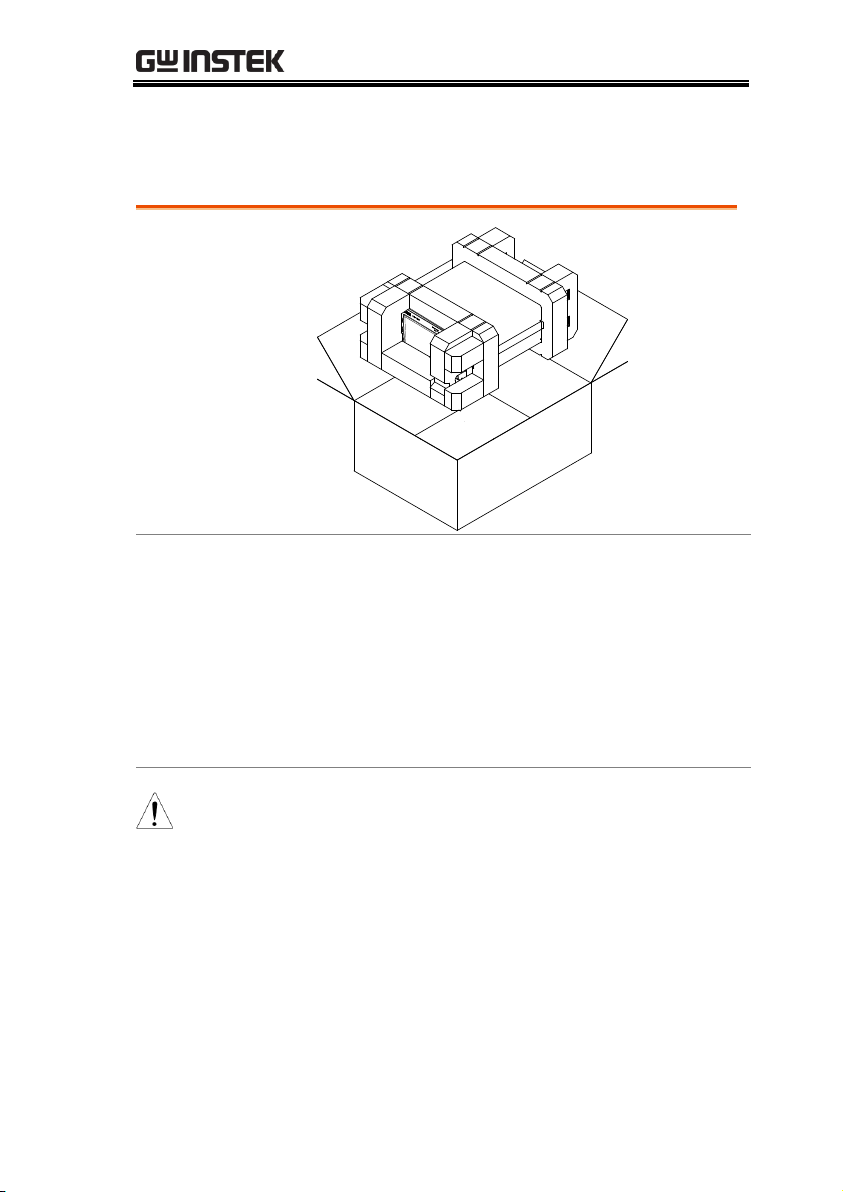
Opening the box
Contents
(single unit)
GPT-12000 unit
Quick Start Guide
User manual CD
CTC (Calibration
Traceable Certificate)
Power cord x1 (region
dependent)
GHT-115 test leads x1
GTL-215 GB test leads
x1 (GPT-12004)
GHT-119 Remote
terminal cable
Interlock key
Note
Keep the packaging, including the box, polystyrene
foam and plastic envelopes should the need arise
to return the unit to GW Instek.
Package Contents
Check the contents before using the GPT-12000 series.
13
GPT-10000 Series User Manual
1
2
3
4 5
6
7
8
9
0
A
B
C
D
E
F
G
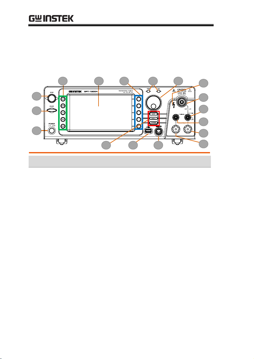
Item
Description
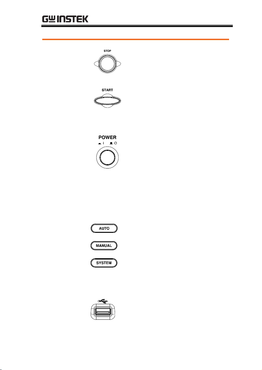
1
STOP Button
2
START Button
3
POWER Switch
4
Test Function Keys (Green Zone)
5
Display
6
Mode Keys (AUTO, MANUAL, SYSTEM in Red Zone)
7
Soft Keys (Blue Zone)
8
USB A-Type Host Port
9
PASS/FAIL Indicators
0
REMOTE Terminal
A
Scroll Wheel
B
HIGH VOLTAGE Indicator
C
HIGH VOLTAGE Output Terminal
D
SENSE L & RETURN Terminal
E
SENSE H & Output Terminal
F
SOURCE L (GPT-12004 only)
G
SOURCE H (GPT-12004 only)
Front Panel Overview
GPT-12001/12002/12003/12004
14
GETTING STARTED
STOP button
The STOP button is used to
stop/cancel tests. The STOP button
will also put the safety analyzer in the
READY status to begin testing.
START button
The START button is used to start tests.
The START button can be used to start
tests when the tester is in the READY
status. Pressing the START button will
put the tester in the TEST status.
POWER switch
Turns the power on. The safety
analyzer will always start up with the
last test setting from when the
instrument was last powered down.
Test Function
Keys
The keys indicate the 5 testing functions including
ACW, DCW, IR, GB and CONT. Pressing one of
the keys enters the function settings.
Display
7” Color TFT LCD display in 800 X 480 resolution
AUTO button
Press to enter the AUTO test mode.
MANUAL button
Press to enter the MANUAL test mode.
SYSTEM button
Press to enter the SYSTEM mode.
Soft Keys
The Soft keys correspond to the menu keys directly
above on the main display.
USB Host Port
It can connect with USB flash drive
for data storage.
15
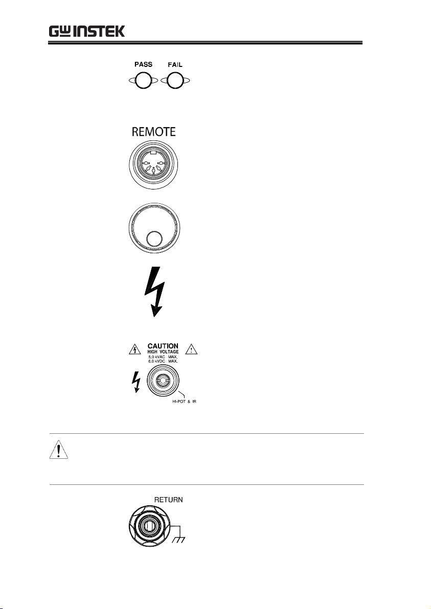
GPT-10000 Series User Manual
Pass/Fail
indicators
The PASS and FAIL indicators
light up upon a PASS or FAIL test
result at the end of a manual test
or automatic test.
REMOTE
terminal
The REMOTE terminal is used to
connect to a remote controller.
Scroll wheel
The scroll wheel is used to edit
parameter values.
HIGH VOLTAGE
indicator
The HIGH VOLTAGE indicator
will light up red when an output
terminal is active. Only after the
test has finished or stopped will
the indicator turn off.
HIGH VOLTAGE
output terminal
The HIGH VOLTAGE terminal
output is used for outputting the
testing voltage in ACW, DCW and
IR tests. The terminal is recessed
for safety. This terminal is used in
conjunction with the RETURN
terminal.
WARNING
USE EXTREME CAUTION.
Do not touch the HIGH VOLTAGE terminal
during testing.
RETURN
terminal
The RETURN terminal is used
for ACW, DCW, IR and CONT
tests.
16
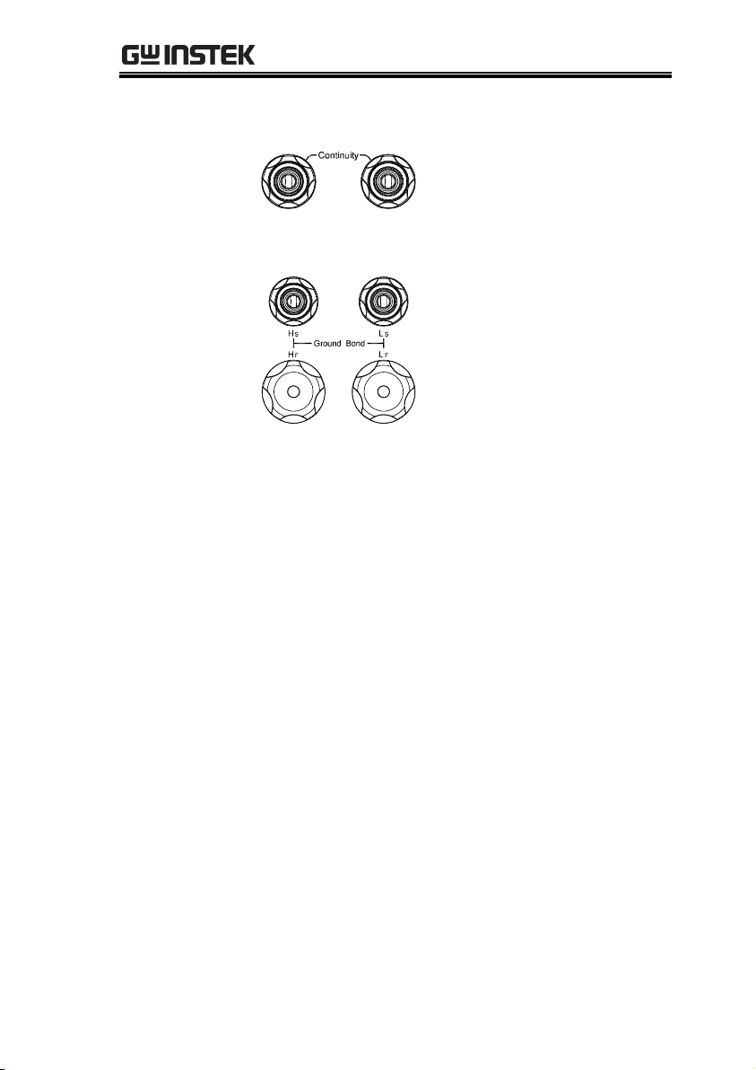
GETTING STARTED
OUTPUT and
RETURN
terminals
All models
The OUTPUT terminal (red)
and RETURN terminal (black)
are used for CONT
(Continuity) test.
SENSE H/L and
SOURCE H/L
terminals
GPT-12004 only
The SENSE H, SENSE L,
SOURCE H and SOURCE L,
terminals are used for GB
(Ground Bond) test.
17
GPT-10000 Series User Manual
1
3
7 8 9 A
B
C
D
2
4
5
6
E
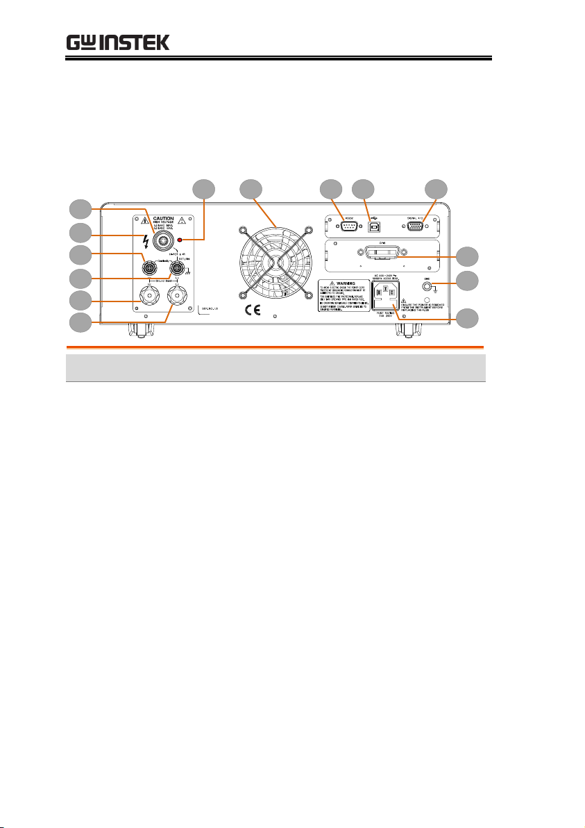
Item
Description
1
HIGH VOLTAGE Output Terminal
2
HIGH VOLTAGE Indicator
3
SENSE H & Output Terminal
4
SENSE L & RETURN Terminal
5
SOURCE H (GPT-12004 only)
6
SOURCE L (GPT-12004 only)
7
Fan 8 RS-232 Port
9
USB B-Type Interface Port
A
Signal I/O Port
B
GPIB Port (Optional)
C
GND
D
AC Mains Input (Power Cord Socket)
E
HIGH VOLTAGE pilot lamp
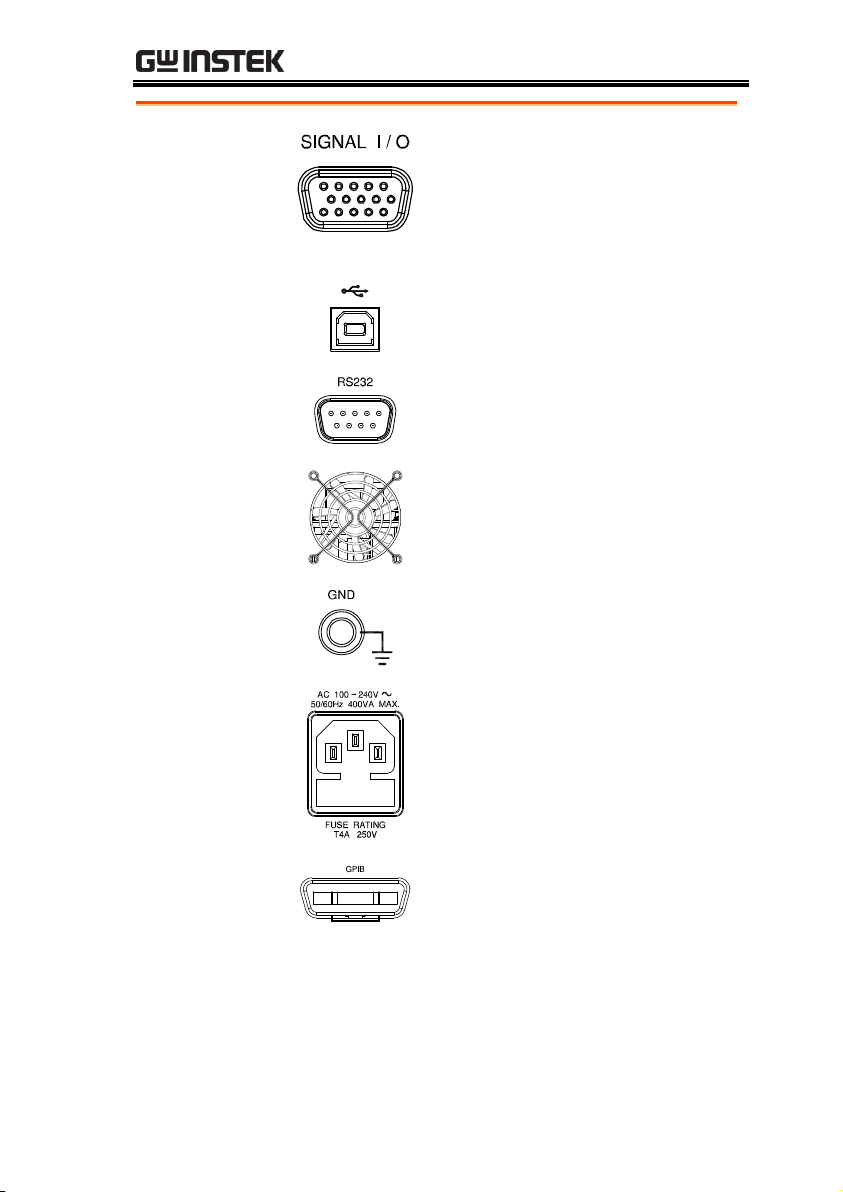
Rear Panel Overview
GPT-12001/12002/12003/12004
18
GETTING STARTED
SIGNAL I/O port
The SIGNAL I/O port is used to
monitor the tester status (PASS,
FAIL, TEST) and input (START/
STOP signals). It is also used with
the Interlock key.
USB B-Type port
The USB B-Type port is used for
remote control.
RS232 interface
port
The RS-232 port is used for remote
control and firmware updates.
Fan/Fan Vents
Exhaust fan. Allow enough room
for the fan to vent. Do not block the
fan openings.
GND
Connect the GND (ground)
terminal to the earth ground.
AC Mains Input
AC Mains Input for Power Cord
Socket: 100 – 240 VAC ±10%.
The fuse holder contains the AC
mains fuse. For fuse replacement
details, see page 45.
Optional GPIB
port
Optional GPIB interface for remote
control.
19
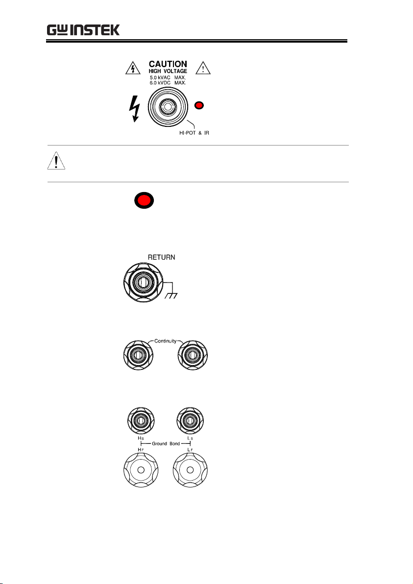
GPT-10000 Series User Manual
HIGH VOLTAGE
output terminal
The HIGH VOLTAGE
terminal output is used for
outputting the testing voltage
in ACW, DCW and IR tests.
The terminal is recessed for
safety and used in conjunction
with the RETURN terminal.
WARNING
USE EXTREME CAUTION. Do not touch the
HIGH VOLTAGE terminal during testing.
HIGH
VOLTAGE pilot
lamp
The HIGH VOLTAGE pilot lamp will
light up red when an output terminal is
active. Only after the test has finished
or stopped will the lamp turn off.
RETURN
terminal
The RETURN terminal is
used for ACW, DCW, IR and
CONT tests.
OUTPUT and
RETURN
terminals
All models
The OUTPUT terminal (red)
and RETURN terminal
(black) are used for CONT
(Continuity) test.
SENSE H/L and
SOURCE H/L
terminals
GPT-12004 only
The SENSE H, SENSE L,
SOURCE H and SOURCE L,
terminals are used for GB
(Ground Bond) test.
20
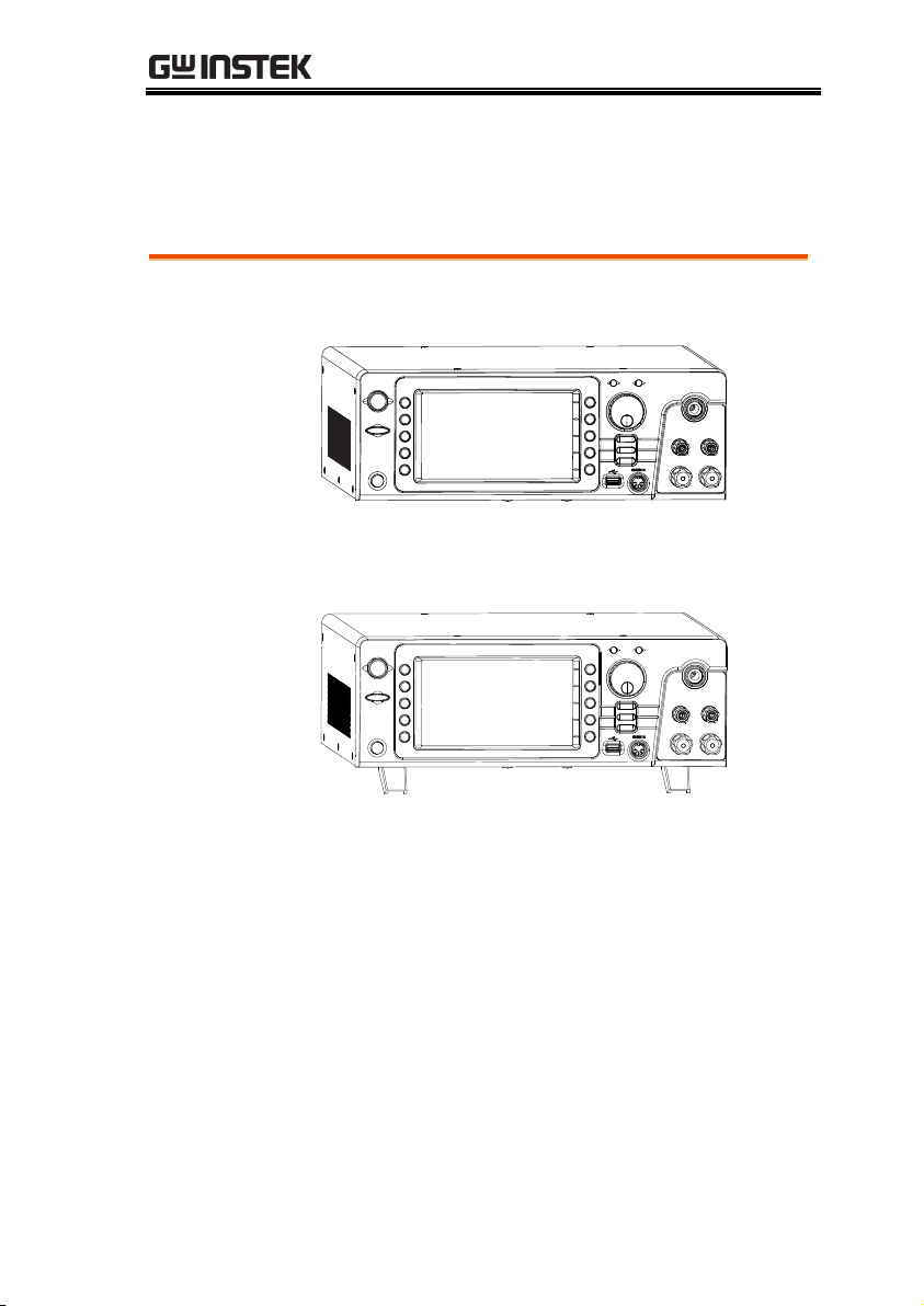
GETTING STARTED
Horizontal
position
Place the unit on a flat surface horizontally.
Tilt stand
position
Gently pull the 2 stands out from the bottom and
the unit will be placed in the tilt stand position.
Set Up
Tilting the Stand
21

GPT-10000 Series User Manual
Background
The GPT-12000 accepts line voltages of
100 - 240V at 50Hz or 60Hz.
Steps
1. Connect the power cord to
the AC Mains Input socket
on the rear panel.
2. If the power cord does not
have an earth ground,
ensure the ground
terminal is connected to an
earth ground.
Warning
Ensure the power cord is connected to an earth
ground. Failure could be harmful to the operator
and instrument.
3. Press the Power button.
4. When the unit is powered up, the display will
show the last time parameters in either MANU
or AUTO test mode as shown below.
Line Voltage Connection and Power Up
22
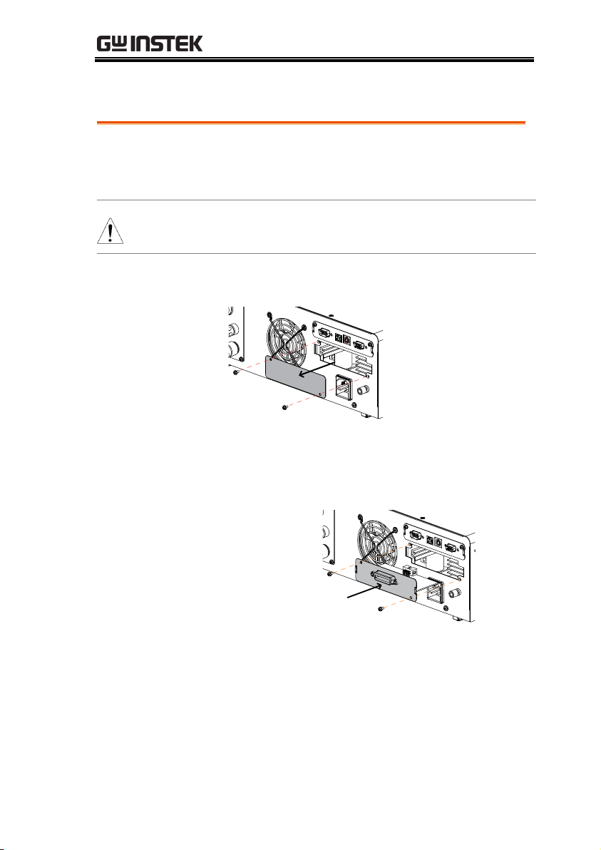
GETTING STARTED
Background
The optional GPIB is a user-installable option.
Follow the instructions below to install the
GPIB card.
WARNING
Before installing optional GPIB card ensure the GPT12000 is turned off and disconnected from power.
Steps
1. Remove screws from the rear panel cover plate.
2. Insert the GPIB card into the opening of rear
panel. Push the card gently until it is fully
inserted followed by fastening the screws.
GPIB Card
Installing the Optional GPIB Card
23
GPT-10000 Series User Manual
Background
The GPT-12000 is a high voltage instrument
that outputs dangerous voltages. The following
section describes precautions and procedures
that must be followed to ensure a safe work
environment.
WARNING
The GPT-12000 generates voltages in excess of
5kVAC or 6kVDC. Follow all safety precautions,
warnings and directions given in the following
section when using the instrument.
1. Only technically qualified personnel should be
allowed to operate the safety analyzer.
2. The operating workplace must be fully isolated,
especially when the instrument is in operation.
The instrument should be clearly labeled with
appropriate warning signage.
3. The operator should not wear any conductive
materials, jewelry, badges, or other items, such
wrist watches.
4. The operator should wear insulation gloves for
high voltage protection.
5. Ensure the earth ground of the line voltage is
properly grounded.
6. Ensure any devices that are adversely affected
by magnetic fields are not placed near the
tester.
Workplace Precautions
24

GETTING STARTED
Background
The GPT-12000 is a high voltage instrument
that outputs dangerous voltages. The following
section describes precautions and procedures
that must be followed to ensure that the tester
is operated in a safe manner.
WARNING
The GPT-12000 generates voltages of up to 5kVAC
or 6kVDC. Follow all safety precautions, warnings
and directions given in the following section when
using the instrument.
1. Never touch the safety analyzer, lead wires,
terminals, probes and other connected
equipment when the tester is testing.
2. Do not turn the safety analyzer on and off
quickly or repeatedly. When turning the power
off, please allow a few moments before turning
the power back on. This will allow the
protection circuits to properly initialize.
Do not turn the power off when a test is
running, unless in an emergency.
3. Only use those test leads supplied with the
instrument. Leads with inappropriate gauges
can be dangerous to both the operator and the
instrument.
For GB testing, never use the Sense leads on the
SOURCE terminals.
4. Do not short the HIGH VOLTAGE terminal
with ground. Doing so could charge the chassis
to dangerously high voltages.
Operating Precautions
25

GPT-10000 Series User Manual
5. Ensure the earth ground of the line voltage is
properly grounded.
6. Only connect the test leads to the HIGH
VOLTAGE/SOURCE H/SENSE H terminals
before the start of a test. Keep the test leads
disconnected at all other times.
7. Always press the STOP button when pausing
testing.
8. Do not leave the safety analyzer unattended.
Always turn the power off when leaving the
testing area.
9. When remotely controlling the safety analyzer,
ensure adequate safety measures are in place to
prevent:
Inadvertent output of the test voltage.
Accidental contact with the instrument during
testing. Ensure that the instrument and DUT are
fully isolated when the instrument is remotely
controlled.
10. Ensure an adequate discharge time for the
DUT.
When DCW or IR tests are performed, the DUT,
test leads and probes become highly charged.
The GPT-12000 has discharge circuitry to
discharge the DUT after each test. The time
required for a DUT to discharge depends on the
DUT and test voltage.
Never disconnect the safety analyzer before a
discharge is completed.
26

GETTING STARTED
Background
The GPT-12000 is a high voltage device and as
such, daily safety checks should be made to
ensure safe operation.
1. Ensure all test leads are not broken and are free
from defects such as cracks or splitting.
2. Ensure the safety analyzer is always connected
to an earth ground.
3. Test the safety analyzer operation with a low
voltage/current output:
Ensure the safety analyzer generates a
FAIL judgment when the HIGH
VOLTAGE and RETURN terminals are
shorted (using the lowest voltage/current as
the testing parameters).
WARNING
Do not use high voltages/currents when the HIGH
VOLTAGE and RETURN terminals are shorted. It
may result in damage to the instrument.
Basic Safety Checks
27

GPT-10000 Series User Manual
Menu Tree ...................................................................... 30
Menu Tree Overview ............................................................................... 31
Test Lead Connection ...................................................... 35
ACW, DCW, IR Connection ................................................................... 35
GB Connection .......................................................................................... 36
CONT Connection.................................................................................... 37
Manual Tests .................................................................. 38
Setting the Test Function ......................................................................... 39
Choose/Recall a Manual Test Number ................................................. 40
Creating a MANU Test File Name ......................................................... 41
Setting the Upper and Lower Limits ..................................................... 42
Setting the Test Time ............................................................................... 44
Setting the Ramp Up Time ...................................................................... 46
Setting the Ramp Down Time ................................................................ 48
Setting the Test Voltage or Test Current ............................................... 50
Setting the Test Frequency ...................................................................... 52
Setting a Reference Value ........................................................................ 53
Setting an Initial Voltage ......................................................................... 54
Setting the Wait Time .............................................................................. 56
Setting the ARC Function........................................................................ 58
Setting MAX HOLD ................................................................................. 61
Setting PASS HOLD ................................................................................. 62
Setting IR Mode ........................................................................................ 63
Setting GND OFFSET .............................................................................. 65
Setting GB Contact ................................................................................... 67
Zero Check for the Test Leads ................................................................ 69
Setting the Grounding Mode .................................................................. 72
Running a MANU Test ............................................................................ 76
PASS / FAIL MANU Test ....................................................................... 81
OPERATION
28

OPERATION
Special MANU Test Mode (000) ...................................... 87
Sweep Function .............................................................. 89
Automatic Tests ............................................................. 92
Choose/Recall an AUTO Test ................................................................93
Creating an AUTO Test File Name ........................................................94
Adding a Step to the AUTO Test ...........................................................95
Continuous AUTO Tests .........................................................................97
AUTO Test Page Editing .........................................................................99
Running an Automatic Test ..................................................................104
Automatic Test Results ..........................................................................110
29
GPT-10000 Series User Manual
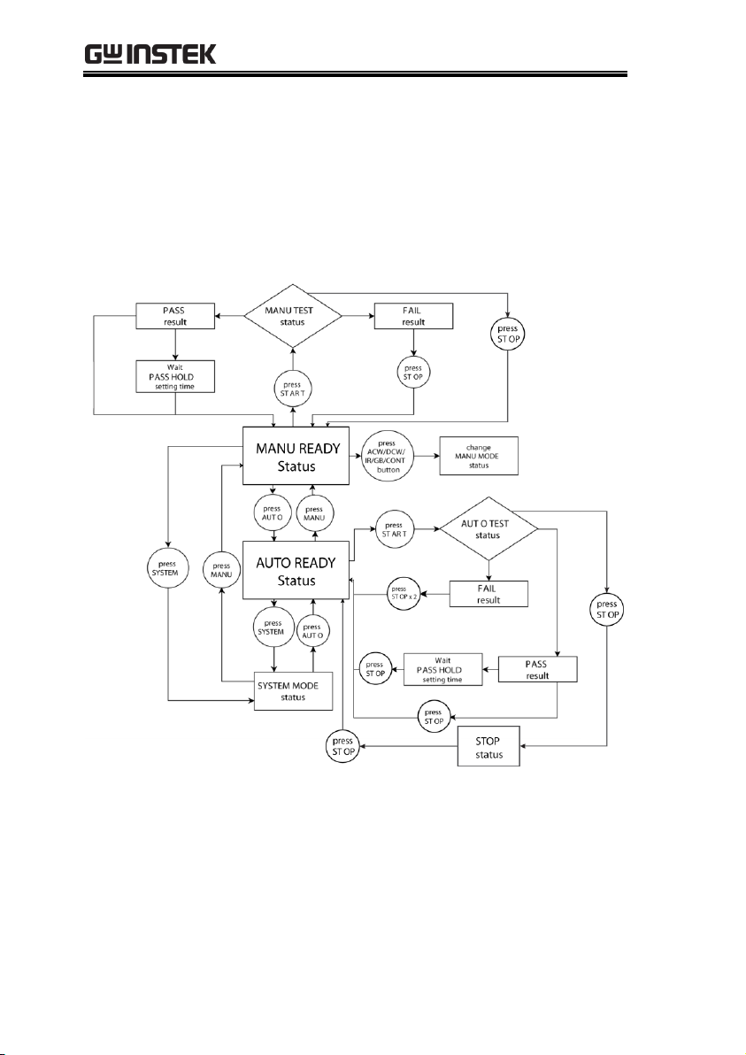
Menu Tree
This section describes the overall structure of the operation statuses
and modes for the GPT-12000 safety analyzers. The testers have
two main testing modes (MANU, AUTO), one system mode
(SYSTEM) and 5 main operation statuses (READY, TEST, PASS,
FAIL and STOP).
30
 Loading...