

Page 1

GPS
4303/ 4251/ 3303/ 2303
Verification/ Adjustment Manual
GPS-4303/ 4251/ 3303/ 2303
Page 2

Page 3

Table of Contents
Table of Contents
How to Use this Manual................................................ 4
Specification............................................................... 5
Front Panel ................................................................ 7
Performance Verification .............................................. 9
Overall Procedure............................................................
Verification Equipment..................................................... 9
Output Voltage Verification ..............................................10
Tracking Series Voltage Verification...................................12
Output Current Verification..............................................14
Tracking Parallel Current Verification .................................16
Current Load Regulation Verification .................................18
Ripple Current Verification...............................................20
Voltage Load Regulation Verification..................................22
Tracking Series Load Regulation/ Ripple Verification ............24
Ripple Voltage Verification ...............................................26
Recording Tables............................................................28
9
Adjustment ...............................................................31
Overall Procedure...........................................................31
Adjustment Equipment....................................................31
Opening the Case...........................................................32
Adjustment Point ...........................................................33
Output Voltage Adjustment..............................................37
Tracking Series Voltage Adjustment ..................................40
Output Current Adjustment .............................................42
Tracking Parallel Current Adjustment.................................
Overload Indicator Adjustment.........................................
3
44
46
Page 4

GPS Verification/ Adjustment Manual
How to Use this Manual
This manual describes how to verify and adjust the performance of
GPS-4303/ 4251/ 3303/ 2303 Multiple Output D.C. Power Supplies.
Specification, page
It also shows the locations of relevant verification and adjustment
procedures in this manual.
Front Panel, page
indicators. The Default Settings column shows the basic panel settings
applicable to all verification and adjustment items.
Performance Verification, page9, shows how to verify GPS performance,
step by step. Check the necessary equipment and the overall procedure
before start working on each item.
Adjustment, page31, shows how to adjust GPS specification. Same as
Performance Verification, check the equipment and the overall procedure
before start working on each item.
5, shows GPS electronic and mechanical specifications.
7, describes the front panel switches, terminals, and
4
Page 5
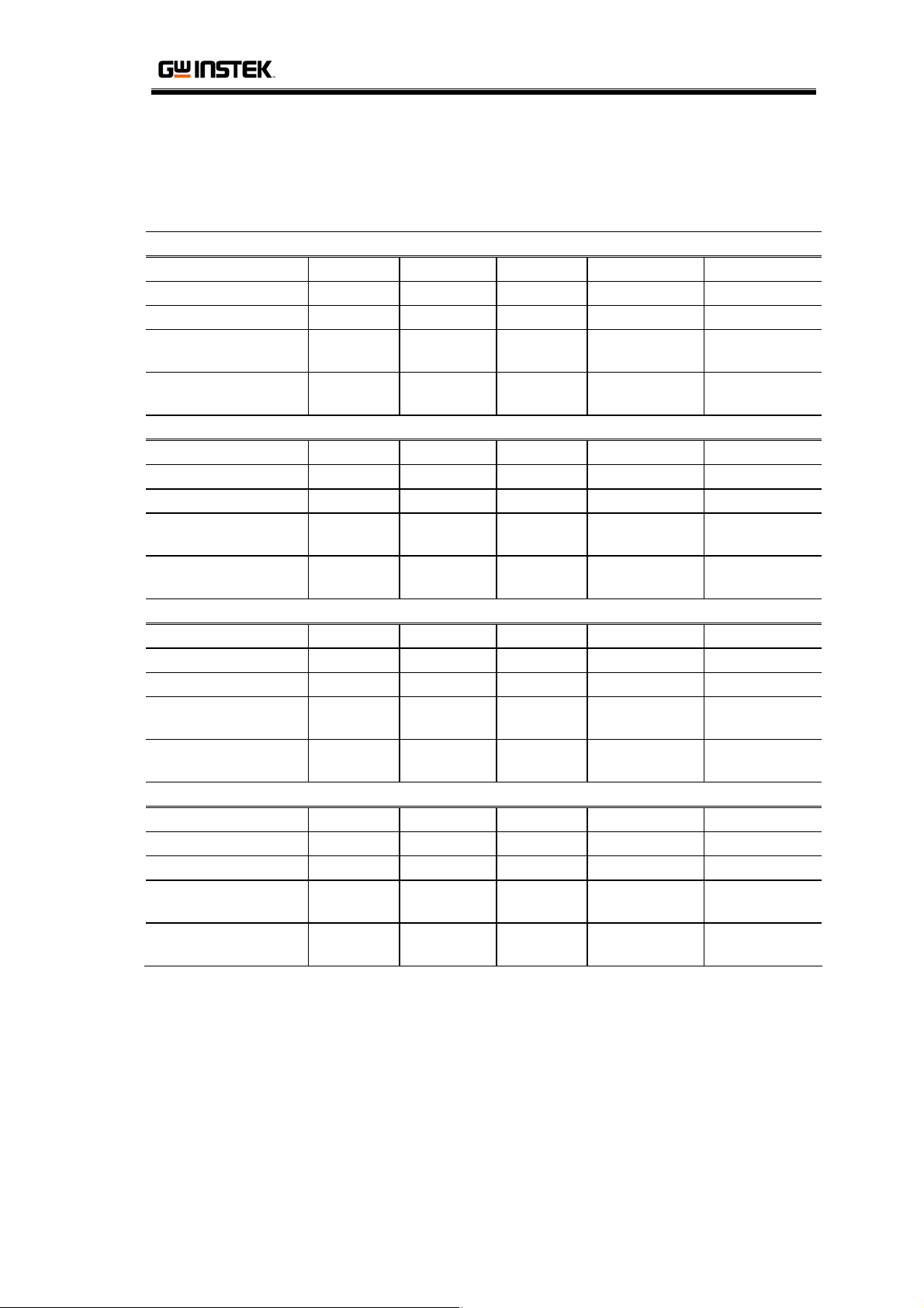
Specification
Specification
GPS-4303
Output Mode CH1, 2 CH3 CH4 Verification Adjustment
Voltage 0 ~ 30V 2.2 ~ 5.2V 8 ~ 15V Page10 Page37
Current 0 ~ 3A 1A Max. 1A Max. Page14 Page42
Tracking Series
Voltage
Tracking Parallel
Current
Output Mode CH1, 2 CH3 CH4 Verification Adjustment
Voltage 0 ~ 25V 3 ~ 6V 8 ~ 15V Page10 Page37
Current 0 ~ 0.5A 2.5A Max. 1A Max Page14 Page42
Tracking Series
Voltage
Tracking Parallel
Current
Output Mode CH1, 2 CH3 CH4 Verification Adjustment
Voltage 0 ~ 30V 5V Fixed --- Page10 Page37
Current 0 ~ 3A 3A Max. --- Page14 Page42
Tracking Series
Voltage
Tracking Parallel
Current
Output Mode CH1, 2 CH3 CH4 Verification Adjustment
Voltage 0 ~ 30V --- --- Page10 Page37
Current 0 ~ 3A --- --- Page14 Page42
Tracking Series
Voltage
Tracking Parallel
Current
0 ~ 60V --- --- Page
0 ~ 6A --- --- Page
GPS-4251
0 ~ 50V --- --- Page
0 ~ 1A --- --- Page
GPS-3303
0 ~ 60V --- --- Page
0 ~ 6A --- --- Page
GPS-2303
0 ~ 60V --- --- Page
0 ~ 6A --- --- Page
12 Page40
16 Page44
12 Page40
16 Page44
12 Page40
16 Page44
12 Page40
16 Page44
(Continued on next page)
5
Page 6
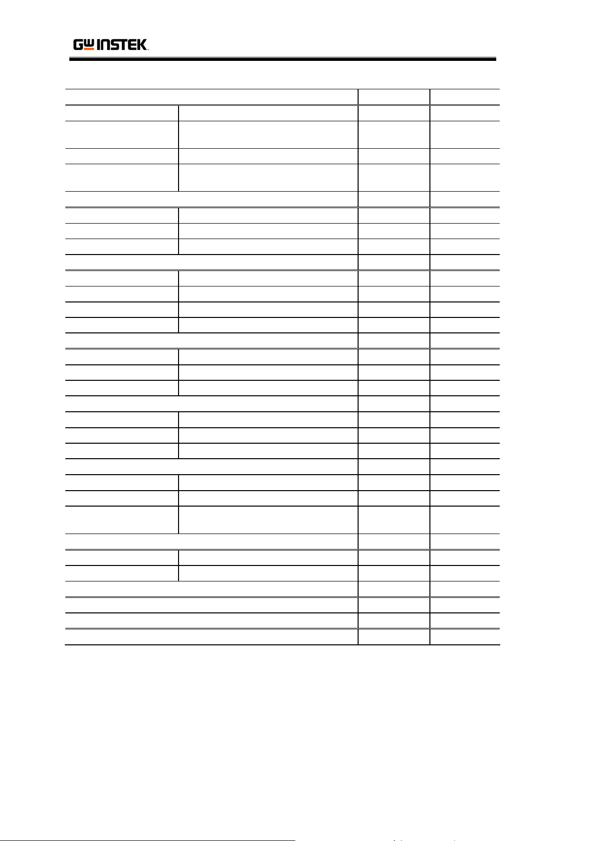
GPS Verification/ Adjustment Manual
Constant Voltage Operation (CH1, CH2) Verifi c ation Adju s tment
Line Regulation ≤ 0.01% + 3mV --- ---
Load Regulation
Ripple & Noise ≤ 1mVrms, 5Hz ~ 1MHz Page26 ---
Recovery Time
Constant Current Operation (CH1, CH2) Verificati o n Adjustme n t
Line Regulation ≤ 0.2% + 3mA --- --Load Regulation ≤ 0.2% + 3mA Page18 --Ripple Current ≤ 3mArms Page20 ---
Tracking Operation (CH1, CH2) Verifi c ation Adju s tment
Tracking Error ≤ 0.5%(CH1) + 10mV Page12 Page41
Series Regulation ≤ 300mV --- --Load Regulation ≤ 0.01% + 3mV Page24 --Ripple & Noise ≤ 2mVrms, 5Hz ~ 1MHz Page24 ---
Line Regulation ≤ 5mV --- --Load Regulation ≤ 15mV Page22 --Ripple & Noise ≤ 2mVrms, 5Hz ~ 1MHz Page26 ---
Line Regulation ≤ 5mV --- --Load Regulation ≤ 10mV Page22 --Ripple & Noise ≤ 2mVrms, 5Hz ~ 1MHz Page26 ---
Model 3 Digits, 0.5” LED display --- --Out ON Accuracy ± (0.5% rdg + 2 digits) Page10, 14 Page38, 43
Out OFF Accuracy
Chassis and Terminal ≥ DC 500V/ 20MΩ --- --Chassis and AC Cord ≥ DC 500V/ 30MΩ --- ---
AC 100V/ 120V/ 220V (± 10%)/ 230V (+10% ~ −6%), 50/ 60Hz --- ---
255(W) x 145(H) x 265(D) mm, 7kg *GPS-4251: 6.3kg --- ---
≤ 0.01% + 3mV (rating current ≤ 3A)
≤ 0.02% + 5mV (rating current > 3A)
≤ 100μS (50% Load Change,
Minimum Load 0.5A)
CH3 Output Verifi c ation Adju s tment
CH4 Output Verifi c ation Adju s tment
Meter Verificat i on Adjustm e nt
± (0.5% rdg + 8 digits)
* GPS-2303: ± (0.5% rdg + 2 digits)
Insulation Ve rificatio n A djustmen t
Power Source Ver i f ication A d j ustment
Dimensions & Weight Verifi c ation Adju s tment
Page22 ---
--- ---
Page
14, 16
10, 12,
Page
43, 45
39, 41,
6
Page 7
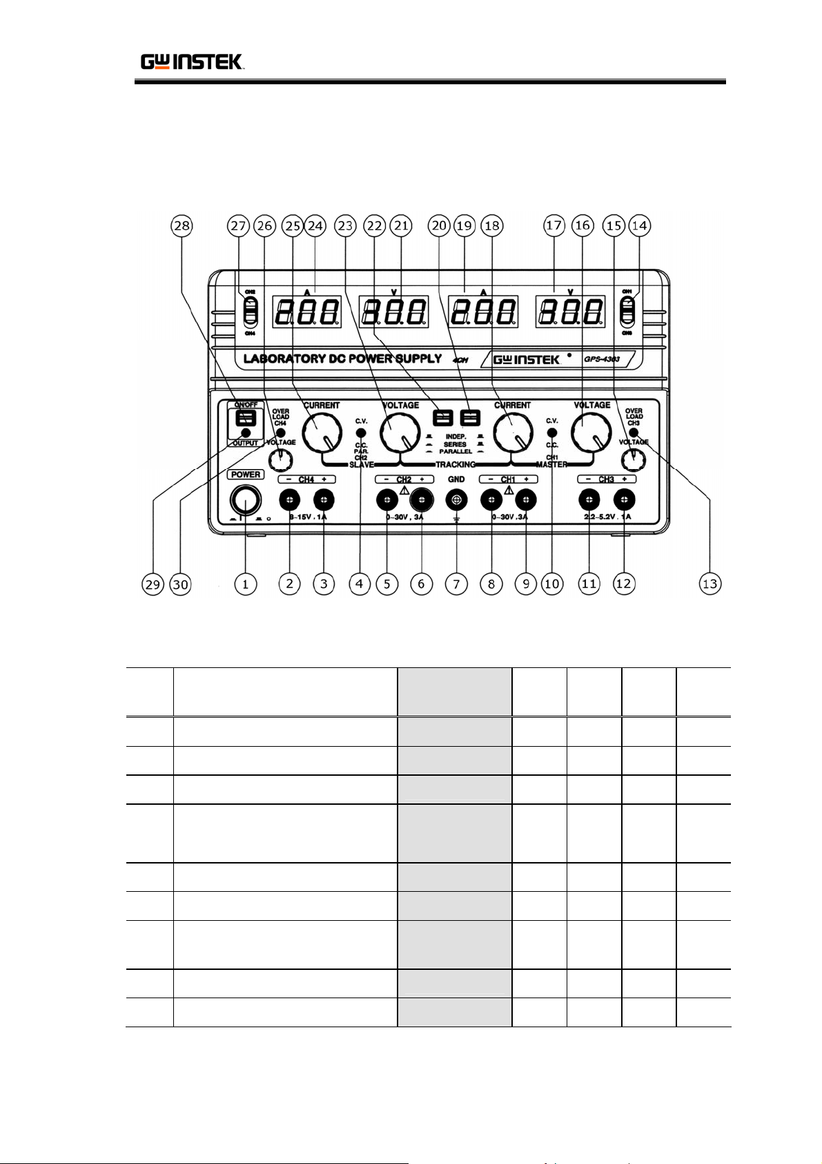
Front Panel
Front Panel
Description and Default Settings
No Description
Default
Settings
GPS-
4303
GPS-
4251
GPS-
3303
GPS-
2303
1 Power Switch ON * * * *
2 CH4 − Output Terminal * *
3 CH4 + Output Terminal * *
CH2 C.V./ C.C. Indicator
Green : Constant Voltage (C.V.)
4
Red : Constant Current (C.C.)
* * * *
5 CH2 − Output Terminal * * * *
6 CH2 + Output Terminal * * * *
7 GND Terminal
Connect to
Ground
* * * *
8 CH1 − Output Terminal Connected * * * *
9 CH1 + Output Terminal Connected * * * *
7
Page 8
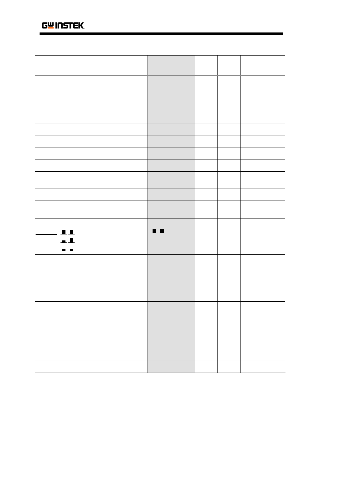
GPS Verification/ Adjustment Manual
No Description
CH1 C.V./ C.C. Indicator
10
Green : Constant Voltage (C.V.)
Red : Constant Current (C.C.)
Default
Settings
* * * *
GPS-
4303
GPS-
4251
GPS-
3303
GPS-
2303
11 CH3 − Output Terminal * * *
12 CH3 + Output Terminal * * *
13 CH3 Overload Indicator * * *
14 CH1/ CH3 Selector CH1 * *
15 CH3 Voltage Control Minimum * *
16 CH1 Voltage Control Minimum * * * *
17 CH1/ CH3 Voltage Meter * *
CH1
Only
CH1
Only
18 CH1 Current Control Minimum * * * *
19 CH1/ CH3 Current Meter * *
20
22
Mode Switch
Independent
Series
Parallel
Independent
* * * *
CH1
Only
CH1
Only
21 CH2/ CH4 Voltage Meter * *
CH2
Only
CH2
Only
23 CH2 Voltage Control Minimum * * * *
24 CH2/ CH4 Current Meter * *
CH2
Only
CH2
Only
25 CH2 Current Control Minimum * * * *
26 CH4 Voltage Control Minimum * *
27 CH2/ CH4 Selector CH2 * *
28 Output Switch OFF * * * *
29 Output Indicator * * * *
30 CH4 Overload Indicator * *
8
Page 9

Performance Verification
Performance Verification
Overall Procedure
1. Prepare the Equipment according to the following table.
2. Set the front panel according to the
3. Verify a specification item and record the result (page10 to 26).
The recording tables are at the end of this chapter (page28).
4. Repeat step 3 for all items.
5. In case of over- or under-specification, continue with the
relevant item in the Adjustment chapter (page31).
Verification Equipment
Equipment Required Specification Used in
• AC & DC Voltage
Digital
Multimeter
2nd Digital
Multimeter
Electronic Load
AC Power
Supply
GPS –
Multimeter
cable
GPS – 2nd
Multimeter
cable
GPS –
Electronic Load
cable
Calculator
Accuracy: < ±0.1%
• DC Current Range: ≥ 6A
• DC Current Accuracy:
<±0.1%
• AC & DC Voltage
Accuracy: < ±0.1%
• DC Voltage Range: ≥ 60V
• DC Current Range: ≥ 6A
• CV, CC, CR Mode
• Short Mode
• Capacity: ≥ 1k VA
• Frequency: 50 – 60Hz
• Line Voltage: ±10%
*230V: −6% ~ +10%
• Vo lt ag e rating: > 60V
• Current rating: > 6A
• Vo lt ag e rating: > 30V • Ripple Current
• Vo lt ag e rating: > 60V
• Current rating: > 6A
• For calculating the
acceptance ranges
• Ripple Current
• Load Regulation
• Ripple Voltage
• Ripple Current
• Ripple Voltage
• Load Regulation
• Ripple Voltage
• Ripple Current
All items
All items ---
All items ---
Default Settings
Recommended
• GDM-8245
• GDM-8246
• GDM-8245
• GDM-8246
• Agilent
N3305A
• APS-9102
• Agilent 6813B
---
---
(page7).
Model
9
Page 10

GPS Verification/ Adjustment Manual
Output Voltage Verification
Here we verify Minimum Output Voltage, Maximum Output Voltage, and
Voltage Meter Accuracy.
Connection
GPS Series
Digital Multimeter
V
A
-1 +
- 3 +- 2 +- 4 +
Verification steps
1. Set the front panel according to
Default Settings
, page7.
2. Connect the Multimeter to CH1 and turn ON the Output
Switch.
Minimum Output V oltage
3. (CH1, CH2 only) Turn up the Current Control to full.
4. (CH1, CH2 only) Make sure the indicator shows C.V. (green).
5. Record the Multimeter readout as Minimum Output Voltage.
Maximum Output Voltage
6. Turn up the Voltage Control to full.
10
7. (CH1, CH2 only) Make sure the indicator shows C.V. (green).
8. Record the Multimeter readout as Maximum Output Voltage.
Out ON Meter Accuracy
9. Record the GPS readout. Calculate the difference between the
previous Multimeter readout and record it as Out ON Meter
Accuracy.
Out OFF Meter Accuracy
10. Turn OFF the Output Switch.
Page 11
Performance Verification
11. Record the GPS readout. Calculate the difference between the
previous GPS readout (Output ON) and record it as Out OFF
Meter Accuracy.
12. Switch the GPS connection to the next channel and turn ON
the Output Switch.
13. Repeat step 3 to 12 for CH2, CH3, and CH4.
Acceptance range: Output Voltage
GPS-4303 GPS-4251 GPS-3303 GPS-2303
Min: < −30mV
CH1
Max: 30V +3% ~
+8% (30.9 ~ 32.4)
Min: < −30mV
CH2
Max: > CH1 +0.2V
Min: 2.2V ±8%
(2.024 ~ 2.376)
CH3
Max: 5.2V ±8%
(4.784 ~ 5.616)
Min: 8.0V ±8% (7.36 ~ 8.64)
CH4
Max: 15.0V ±8% (13.8 ~ 16.2)
Min: < −30mV
Max: 25V +3% ~
+8% (25.75 ~ 27)
Min: 3.0V ±8%
(2.76 ~ 3.24)
Max: 6.0V ±8%
(5.52 ~ 6.48)
Min: < −30mV
Max: 30V +3% ~ +8% (30.9 ~
32.4)
Min: < −30mV
Max: > CH1 +0.2V
Min: 5.0V ±8%
(4.6 ~ 5.4)
Max: N/A
Acceptance range: Voltage Meter Accuracy
GPS-4303 GPS-4251 GPS-3303 GPS-2303
Out ON:
CH1
Out ON: ±(0.5% rdg + 2digits)
CH2
Out OFF: ±(0.5% rdg + 8digits)
CH3 N/A
CH4
±(0.5% rdg +
2digits)
Out OFF:
±(0.5% rdg +
8digits)
Out ON:
±(0.5% rdg +
2digits)
Out OFF: N/A
When out of range…
Refer to
11
Output Voltage
adjustment, page37.
Page 12

GPS Verification/ Adjustment Manual
Tracking Series Voltage Verification
Here we verify Tracking Series Minimum Voltage, Tracking Error, and
Tracking Series Meter Accuracy.
Connection
GPS Series
Digital Multimeter
V
A
-1 +
- 3 +- 2 +- 4 +
Verification steps
1. Set the front panel according to
Default Settings
, page7.
2. Connect the Multimeter to CH1 and turn ON the Output
Switch.
Tracking Series Minimum Voltage
3. Turn up the Current Control to full and set the Tracking
Switch to Series .
4. Make sure the indicator shows C.V. (green) for both CH1 and
CH2.
5. Turn up the Voltage control to 1.0V and record the Multimeter
12
readout.
6. Switch the GPS connection to CH2, turn up the Current
Control to full, and record the Multimeter readout.
7. Calculate the difference between the CH1 readout and record
it as Tracking Series Minimum Voltage.
Tracking Error
8. Switch the GPS connection to CH1, turn up the Voltage
Control to full, and record the Multimeter readout.
Page 13

Performance Verification
9. Make sure the indicator shows C.V. (green) for both CH1 and
CH2.
10. Switch the GPS connection to CH2, turn up the Voltage
Control to full, and record the Multimeter readout.
11. Calculate the difference between CH1 and record it as
Tracking Error.
Tracking Series Meter Accuracy
12. Switch the GPS connection to CH1 and record the GPS
readout. Turn OFF the Output Switch and record the GPS
readout.
13. Calculate the difference between Output ON and OFF GPS
readout and record it as CH1 Tracking Series Meter Accuracy.
14. Switch the GPS connection to CH2 and record the GPS
readout. Turn ON the Output Switch and record the GPS
readout.
15. Calculate the difference between Output ON and OFF GPS
readout and record it as CH2 Tracking Series Meter Accuracy.
Acceptance range
GPS-4303 GPS-4251 GPS-3303 GPS-2303
Minimum Voltage: ±10mV
Error: ≤ 0.5% of CH1 + 10mV
CH1
CH2
Meter Accuracy: ±(0.5% rdg +
8digits)
Minimum Voltage: ±10mV
Error: ≤ 0.5% of CH1 + 10mV
Meter
Accuracy: ±
(0.5% rdg +
8digits)
N/A
When out of range…
Refer to
Tracking Series Voltage
adjustment, page40.
13
Page 14
GPS Verification/ Adjustment Manual
Output Current Verification
Here we verify Minimum Output Current, Maximum Output Current, and
Current Meter Accuracy.
Connection
GPS Series
Digital Multimeter
V
A
-1 +
- 3 +- 2 +- 4 +
Verification steps
1. Set the front panel according to
Default Settings
, page7.
2. Connect the Multimeter to CH1 and turn ON the Output
Switch.
Minimum Output Current
3. Turn up the Voltage Control to full.
4. (CH1, CH2 only) Make sure the indicator shows C.C. (red).
5. (CH1, CH2 only) Record the Multimeter readout as Minimum
Output Current.
Maximum Output Current
14
6. (CH1, CH2 only) Turn up the Current Control to full.
7. (CH1, CH2 only) Make sure the indicator shows C.C. (red).
8. (CH3, CH4 only) Make sure the Overload indicator turns on.
9. Record the Multimeter readout as Maximum Output Current.
Out ON Meter Accuracy
10. Record the GPS readout. Calculate the difference between the
previous Multimeter readout and record it as Out ON Meter
Accuracy.
Page 15

Performance Verification
Out OFF Meter Accuracy
11. (CH1, CH2 only) Turn OFF the Output Switch.
12. (CH1, CH2 only) Record the GPS readout. Calculate the
difference between the previous GPS readout (Output ON)
and record it as Output OFF Meter Accuracy.
13. Switch the GPS connection to the next channel and turn ON
the Output Switch.
14. Repeat step 3 to 13 for CH2, CH3, and CH4.
Acceptance range: Output Current
GPS-4303 GPS-4251 GPS-3303 GPS-2303
Min: < −30mA
CH1
Max: 3A +2% ~
+10% (3.06~3.3)
Min: < −30mA
CH2
Max: CH1 < CH2 < CH1+150mA
Min: N/A
CH3
Max: 1.18A ~
1.20A
CH4
Max: 1.12A ~ 1.28A
Min: < −30mA
Max: 0.5A +2%~
+10%(0.51~0.6)
Min: N/A
Max: 2.8A ~ 2.9A
Min: N/A
Min: < −30mA
Max: 3A +2% ~ +10% (3.06~3.3)
Min: < −30mA
Max: CH1 < CH2 <CH1+150mA
Min: N/A
Max: 3.38A ~
3.42A
Acceptance range: Current Meter Accuracy
GPS-4303 GPS-4251 GPS-3303 GPS-2303
CH1
Out ON: ±(0.5% rdg + 2digits)
Out OFF: ±(0.5% rdg + 8digits)
CH2
CH3 N/A
CH4
N/A
Out ON:
±(0.5% rdg +
2digits)
Out OFF:
±(0.5% rdg +
8digits)
Out ON:
±(0.5% rdg +
2digits)
When out of range…
Refer to
Refer to
15
Output Current
adjustment, page42.
Overload Indicator
adjustment, page46.
Page 16

GPS Verification/ Adjustment Manual
Tracking Parallel Current Verification
Here we verify Tracking Parallel Maximum Current and Tracking Parallel
Meter Accuracy.
Connection
GPS Series
Digital Multimeter
V
A
-1 +
- 3 +- 2 +- 4 +
Verification steps
1. Set the front panel according to
Default Settings
, page7.
2. Connect the Multimeter to CH1 and turn ON the Output
Switch.
Tracking Parallel Maximum Current
3. Turn up CH2 Voltage Control, CH2 Current Control, and CH1
Voltage Control to full.
4. Turn up CH1 Current Control to 3.000A by watching the
Multimeter.
5. Set the Tracking Switch to Parallel .
16
6. Record the Multimeter readout as Tracking Parallel Maximum
Current.
Tracking Parallel Meter Accuracy
7. Record the GPS readout.
8. Turn OFF the Output Switch.
9. Record the GPS readout. Calculate the difference between the
previous GPS readout (Output ON) and record it as Tracking
Parallel Meter Accuracy.
Page 17

Performance Verification
Acceptance range: Output Current
GPS-4303 GPS-4251 GPS-3303 GPS-2303
Max: 6.000A Max: 6.000A
Acceptance range: Meter Accuracy
GPS-4303 GPS-4251 GPS-3303 GPS-2303
±(0.5% rdg + 8digits)
When out of range…
Refer to
Tracking Parallel Current
±(0.5% rdg +
8digits)
adjustment, page44.
N/A
17
Page 18

GPS Verification/ Adjustment Manual
Current Load Regulation Verification
Here we verify Current Load Regulation for Independent and Tracking
Parallel mode.
Connection
Connect the Digital Multimeter in series with the Electronic Load
and GPS.
Digital Multimeter
V
A
Electronic Load
+
-
Electronic Load settings
GPS Series
-1 + - 3 +- 2 +- 4 +
GPS-4303 GPS-4251 GPS-3303 GPS-2303
CH1
CH2
30V, 3A 25V, 0.5A
Tracking Parallel
30V, 6A
Tracking Parllel
25V, 1A
30V, 3A
Tracking Parallel 30V, 6A
18
Page 19

Performance Verification
Verification steps
1. Set the front panel according to
Default Settings
, page7 and
turn OFF the Electronic Load output.
2. Connect the Multimeter and Electronic Load to CH1 and turn
ON the Output Switch.
3. Turn ON the Electronic Load output. Set the output value
according to the table on the previous page.
4. Turn up the Voltage Control and Current Control to full.
5. (Tracking Parallel only) Set the Tracking Switch to
Parallel .
6. Record the Multimeter readout.
7. Short the Electronic Load output.
8. Record the Multimeter readout.
9. Calculate the difference between normal and shorted Load
Multimeter readout and record as Current Load Regulation.
10. Set the Electronic Load output to normal (No short).
11. Switch the GPS connection to the next channel and turn ON
the Output Switch.
12. Repeat step 3 to 11 for CH2 and Tracking Parallel (Connect to
CH1).
Acceptance range
GPS-4303 GPS-4251 GPS-3303 GPS-2303
CH1
CH2
≤ 0.2% +3mA
(≤ 9mA)
Tracking Parallel
≤ 0.2% +5mA
(≤ 17mA)
≤ 0.2% +3mA
(≤ 4mA)
Tracking Parallel
≤ 0.2% +5mA
(≤ 7mA)
≤ 0.2% +3mA
(≤ 9mA)
Tracking Parallel
≤ 0.2% +5mA
(≤ 17mA)
19
Page 20

GPS Verification/ Adjustment Manual
Ripple Current Verification
Here we verify Ripple Current for Independent mode.
Connection
Connect the first Digital Multimeter in series with the Electronic
Load and GPS. Connect the second Digital Multimeter in parallel to
GPS.
Digital Multimeter
V
A
Electronic Load
+
-
Electronic Load settings
GPS Series
-1 + - 3 +- 2 +- 4 +
Digital Multimeter
V
A
GPS-4303 GPS-4251 GPS-3303 GPS-2303
CH1
CH2
30V, 3A 25V, 0.5A
30V, 3A
20
Page 21

Performance Verification
Verification steps
1. Set the front panel according to
Default Settings
, page7 and
turn OFF the Electronic Load output.
2. Connect the Multimeter and Electronic Load to CH1 and turn
ON the Output Switch.
3. Turn ON the Electronic Load output. Set the output value
according to the table on the previous page
4. Change the Electronic Load to CR mode.
5. Decrease the Electronic Load value until the C.C. indicator
turns on.
6. Record the first Multimeter readout (DC Current).
7. Record the second Multimeter readout (DC Voltage).
8. Calculate Load Resistance R = (DC Voltage)/ (DC Current).
9. Switch the second Multimeter range to AC mV. Record the
Multimeter readout.
10. Calculate the Ripple Current I = (AC mV)/ (Load Resistance
R).
11. Switch the GPS connection to CH2 and turn ON the Output
Switch.
12. Repeat step 3 to 11 for CH2.
Acceptance range
GPS-4303 GPS-4251 GPS-3303 GPS-2303
CH1
CH2
≤ 3mA rms
≤ 3mA rms
21
Page 22

GPS Verification/ Adjustment Manual
Voltage Load Regulation Verification
Here we verify Voltage Load Regulation for Independent and Tracking
Parallel mode.
Connection
Digital Multimeter
GPS Series
V
A
Electronic Load
-1 + - 3 +- 2 +- 4 +
+
-
Electronic Load settings
GPS-4303 GPS-4251 GPS-3303 GPS-2303
CH1
CH2
CH3 5.2V, 1A 6V, 2.5A 5V, 3A
CH4 15V, 1A
30V, 3A 25V, 0.5A
Tracking Parallel
30V, 6A
Tracking Parllel
25V, 1A
30V, 3A
Tracking Parallel 30V, 6A
22
Page 23

Performance Verification
Verification steps
1. Set the front panel according to
Default Settings
, page7 and
turn OFF the Electronic Load output.
2. Connect the Multimeter and Electronic Load to CH1 and turn
ON the Output Switch.
3. Turn ON the Electronic Load output. Set the output value
according to the table on the previous page.
4. Turn up the Voltage Control and Current Control to full.
5. (Tracking Parallel only) Set the Tracking Switch to Parallel
.
6. Record the Multimeter readout.
7. Turn OFF the Electronic Load output.
8. Record the Multimeter readout.
9. Calculate the difference between Load ON and OFF
Multimeter readout and record as Voltage Load Regulation.
10. Switch the GPS connection to the next channel and turn ON
the Output Switch.
11. Repeat step 3 to 10 for CH2, CH3, CH4, and Tracking Parallel
(Connect to CH1).
Acceptance range: Load Regulation
GPS-4303 GPS-4251 GPS-3303 GPS-2303
CH1
CH2
CH3 ≤ 15mV ≤ 15mV
CH4 ≤ 10mV
≤ 0.01% +3mV
(≤ 6mV)
Tracking Parallel
≤ 0.01% +3mV
(≤ 6mV)
≤ 0.01% +3mV
(≤ 5.5mV)
Tracking Parallel
≤ 0.01% +3mV
(≤ 5.5mV)
≤ 0.01% +3mV
(≤ 6mV)
Tracking Parallel
≤ 0.01% +3mV
(≤ 6mV)
23
Page 24

GPS Verification/ Adjustment Manual
Tracking Series Load Regulation/ Ripple Verification
Here we verify Voltage Load Regulation and Ripple Voltage for Tracking
Series mode.
Connection
Connect the positive side to CH1 + and the negative side to CH2 −.
Digital Multimeter
V
A
Electronic Load
+
-
AC Power Supply
GPS Series
-1 + - 3 +- 2 +- 4 +
Electronic Load settings
GPS-4303 GPS-4251 GPS-3303 GPS-2303
60V, 3A 50V, 0.5A 60V, 3A
24
Page 25

Performance Verification
Verification steps
1. Set the front panel according to
Default Settings
, page7 and
turn OFF the Electronic Load output.
2. Connect the Multimeter and Electronic Load as shown in the
previous page and turn ON the Output Switch.
3. Turn up CH1 Voltage Control and Current Control to full.
4. Turn up CH2 Voltage Control and Current Control to full.
5. Set the Tracking Switch to Series .
Tracking Series Voltage Load Regulation
6. Record the Multimeter readout.
7. Turn ON the Electronic Load output. Set the output value
according to the table on the previous page.
8. Record the Multimeter readout.
9. Calculate the difference between Load ON and OFF
Multimeter readout and record as Tracking Series Load
Regulation.
Tracking Series Ripple Voltage
10. Check the AC Selector on the rear panel for Power Supply
Voltage Rating. Set AC Power to Rating value −10%, 50Hz.
(for 230V, −6%, 50Hz).
11. Record the Multimeter readout (AC Voltage) as Ripple Voltage.
12. Repeat step 11 for AC Power −10%, 60Hz (for 230V, −6%,
50Hz) / +10%, 50Hz/ +10%, 60Hz.
13. Pick up the largest value of the four as Tracking Series Ripple
Voltage.
Acceptance range
GPS-4303 GPS-4251 GPS-3303 GPS-2303
Tracking Series
Load Regulation
≤ 0.01% +3mV
(≤ 9mV)
Tracking Series
Ripple Voltage
≤ 2mVrms
Tracking Series
Load Regulation
≤ 0.01% +3mV
(≤ 8mV)
Tracking Series
Ripple Voltage
≤ 2mVrms
Tracking Series Load Regulation
≤ 0.01% +3mV (≤ 9mV)
Tracking Series Ripple Voltage
≤ 2mVrms
25
Page 26

GPS Verification/ Adjustment Manual
Ripple Voltage Verification
Here we verify Ripple Voltage for Independent and Tracking Parallel mode.
Connection
Digital Multimeter
V
A
Electronic Load
+
-
AC Power Supply
GPS Series
-1 + - 3 +- 2 +- 4 +
Electronic Load settings
GPS-4303 GPS-4251 GPS-3303 GPS-2303
CH1
CH2
CH3 5.2V, 1A 6V, 2.5A 5V, 3A
CH4 15V, 1A
30V, 3A 25V, 0.5A
Tracking Parallel
30V, 6A
Tracking Parallel
25V, 1A
30V, 3A
Tracking Parallel 30V, 6A
26
Page 27

Performance Verification
Verification steps
1. Set the front panel according to
Default Settings
, page7 and
turn OFF the Electronic Load output.
2. Connect the Multimeter and Electronic Load to CH1 and turn
ON the Output Switch.
3. Turn up Voltage Control and Current Control to full.
4. (Tracking Parallel only) Set the Tracking Switch to
Parallel .
5. Turn ON the Electronic Load output. Set the output value
according to the table on the previous page.
6. Check the AC Selector on the rear panel for Power Supply
Voltage Rating. Set AC Power to Rating value −10%, 50Hz.
(for 230V, −6%, 50Hz).
7. Record the Multimeter readout (AC Voltage) as Ripple Voltage.
8. Repeat step 7 for AC Power −10%, 60Hz (for 230V, −6%, 50Hz)
/ +10%, 50Hz/ +10%, 60Hz.
9. Pick up the largest value of the four as Ripple Voltage.
10. Switch the GPS connection to the next channel and turn ON
the Output Switch.
11. Repeat step 3 to 10 for CH2, CH3, CH4, and Tracking Parallel
(Connect to CH1).
Acceptance range
GPS-4303 GPS-4251 GPS-3303 GPS-2303
CH1
CH2
CH3 ≤ 2mVrms
CH4
≤ 1mVrms
≤ 2mVrms
Tracking Parallel
≤ 2mVrms
≤ 1mVrms
Tracking Parallel
≤ 2mVrms
27
Page 28

GPS Verification/ Adjustment Manual
Recording Tables
GPS-4303 GPS-4251 GPS-3303 GPS-2303
CH C.V. Multimeter Pass/ Fail Note
Minimum
Output
Voltag e
Maximum
Output
Voltag e
Out ON
Voltag e
Meter
Accuracy
Out OFF
Voltag e
Meter
Accuracy
Tracking
Series
Minimum
Voltag e
Tracking
Series
Error
Tracking
Series
Meter
Accuracy
1
2
3
4
CH C.V. Multimeter Pass/ Fail Note
1
2
3
4
CH
1
2
3
4
CH
1
2
3
4
CH C.V. Multimeter CH2 – CH1 Pass/ Fail Note
1
2
CH C.V. Multimeter CH2 – CH1
1
2
CH
1
2
ON OFF
ON OFF
ON OFF
ON OFF
V
V
Multimeter
Out ON
GPS Out
ON
ON OFF
ON OFF
ON OFF
ON OFF
GPS Out
OFF
mV
mV
V
V
V
V
( CH1 + 0.2V = V)
GPS Out
ON
V V mV
V V mV
V V mV
V V mV
GPS Out
OFF
V V mV mV
V V mV mV
V V mV mV
V V mV mV
GPS Out
ON
V V mV mV
V V mV mV
Multimeter
GPS Out
ON – OFF
V
V
V
V
GPS Out
ON – OFF
– GPS
mV
mV mV
P F
P F
P F
P F
P F
P F
P F
P F
0.5% rdg +
2 digits
0.5% rdg +
8 digits
P F
10mV +
0.5%(CH1)
0.5% rdg +
8 digits
mV
mV
mV
mV
Pass/ Fail
P F
P F
P F
P F
Pass/ Fail
P F
P F
P F
P F
Pass/ Fail
P F
Pass/ Fail
P F
P F
28
Page 29

Performance Verification
Recording Tables cont.
Minimum
Output
Current
Maximum
Output
Current
Out ON
Current
Meter
Accuracy
Out OFF
Current
Meter
Accuracy
Tracking
Parallel
Maximum
Current
Tracking
Parallel
Meter
Accuracy
Current
Load
Regulation
Tracking
Parallel
Current
Load
Regulation
Ripple
Current
Regulation
CH1
CH2
Voltag e
Load
Regulation
P F
P F
CH C.C. Multimeter Pass/ Fail Note
− GPS
Load
Load
Load
Load
mA
mA
A
A
A
A
mA
P F
P F
P F
P F
P F
P F
0.5% rdg +
2 digits
mV
mV
mV
mV
0.5% rdg +
8 digits
P F
0.5% rdg +
8 digits
Pass/ Fail Note
P F
P F
Pass/ Fail Note
P F
AC Voltage
Pass/ Fail Note
P F
P F
P F
P F
Pass/ Fail
P F
P F
P F
P F
Pass/ Fail
P F
P F
Pass/ Fail
P F
Ripple
Current
1
2
CH C.C. Overload Multimeter Pass/ Fail Note
1
2
3
4
CH Multimeter GPS
1 A A mA
2 A A mA
3 A A mA
4 A A mA
CH GPS Out ON
1 A A mA mV
2 A A mA mV
CH
1 A A
CH GPS Out ON
1 A A mA mV
CH Load ON Load short
1 A A
2 A A mA
CH Load ON Load short
1 A A mA
CH DC Current DC Voltage
1 A V Ω mV mA
2 A V Ω mV mA
CH Load ON Load OFF
1 V V mV
2 V V mV
3 V V mV
4 V V mV
ON OFF
ON OFF
ON OFF
ON OFF
Multimeter
Independent
ON OFF
ON OFF
Multimeter
GPS Out
OFF
Multimeter Parallel Pass/ Fail Note
GPS Out
OFF
GPS Out
ON − OFF
GPS Out
ON − OFF
ON − short
ON − short
Resistance
ON − OFF
29
Page 30

GPS Verification/ Adjustment Manual
Recording Tables cont.
Tracking
Parallel
Voltag e
Load
Regulation
Tracking
Series
Voltag e
Load
Regulation
Tracking
Series
Ripple
Voltag e
Ripple
Voltag e
Ripple
Voltag e
Ripple
Voltag e
Ripple
Voltag e
Tracking
Parallel
Ripple
Voltag e
CH Load ON Load OFF
1 V V mV
CH Load OFF Load ON
1
2
CH AC Power Multimeter Largest Pass/ Fail Note
−10/6%,50Hz mV
+10%, 50Hz mV
1
2
−10/6%,60Hz mV
+10%, 60Hz mV
CH AC Power Multimeter Largest Pass/ Fail Note
−10/6%,50Hz mV
+10%, 50Hz mV
1
−10/6%,60Hz mV
+10%, 60Hz mV
CH AC Power Multimeter Largest Pass/ Fail Note
−10/6%,50Hz mV
+10%, 50Hz mV
2
−10/6%,60Hz mV
+10%, 60Hz mV
CH AC Power Multimeter Largest Pass/ Fail Note
−10/6%,50Hz mV
+10%, 50Hz mV
3
−10/6%,60Hz mV
+10%, 60Hz mV
CH AC Power Multimeter Largest Pass/ Fail Note
−10/6%,50Hz mV
+10%, 50Hz mV
4
−10/6%,60Hz mV
+10%, 60Hz mV
CH AC Power Multimeter Largest Pass/ Fail Note
−10/6%,50Hz mV
+10%, 50Hz mV
1
−10/6%,60Hz mV
+10%, 60Hz mV
V V mV
Load
ON − OFF
Load
ON − OFF
Pass/Fail Note
P F
Pass/Fail Note
P F
P F
P F
P F
P F
P F
P F
30
Page 31

Adjustment
Overall Procedure
1. Prepare the Equipment according to the following table.
2. Open the Case according to the diagram on page32.
Adjustment
3. Set the front panel according to
Default Settings
4. Connect the Multimeter to GPS CH1 and turn ON the Output
Switch.
5. Adjust the specifications according to your needs (page34 to
46). The adjustment points are shown in the diagram: page33
(GPS-4303), page34 (GPS-4251), page35 (GPS-3303), page36
(GPS-2303).
6. When the adjustment is completed, run the Performance
Verification again to verify the result (page9).
Adjustment Equipment
Equipment Required Specification Used in
• AC & DC Voltage
Digital
Multimeter
Electronic Load
GPS –
Multimeter
cable
GPS –
Electronic Load
cable
Flathead Screw
Driver Small
Phillips Screw
Driver Small
Phillips Screw
Driver Large
Accuracy: < ±0.1%
• DC Current Range: ≥ 6A
• DC Current Accuracy:
<±0.1%
• DC Voltage Range: ≥ 60V
• Current Range: ≥ 6A
• Vo lt ag e rating: > 60V
• Current rating: > 6A
• Vo lt ag e rating: > 60V
• Current rating: > 6A
• 1.5mm
• For adjustment
• 2mm
• For adjustment
• 3mm/ 4mm
• For opening the case
All items
• Overload Indicator
All items ---
• Overload Indicator
All items ---
All items ---
All items ---
, page7.
Recommended
Model
• GDM-8245
• GDM-8246
• Agilent
N3305A
---
31
Page 32

GPS Verification/ Adjustment Manual
Opening the Case
1. Take off six screws, 3x6mm, on the side panels.
2. Take off two screws, 4x12mm, holding the belt on the top
panel.
3. Hold the case, slide it behind, and pull it off upward.
32
Page 33

Adjustment
Adjustment Point
GPS-4303
VR801
VR901
VR803
VR303
VR301
VR902
VR601
VR602
Left View
Right View
VR201
VR701
VR101
VR103
VR203
VR702
VR401
VR402
VR306
VR802
VR502
VR903
Top View
VR501
VR804
VR202
VR904
VR703
33
Page 34

GPS Verification/ Adjustment Manual
GPS-4251
VR901
VR902
VR803
VR303
VR301
VR602
VR601
Left View
Right View
VR701
VR702
VR203
VR101
VR401
VR402
VR306
VR802
VR302
VR502
VR903
VR202
Top View
VR804
VR501
VR703
VR904
VR102
Main PCB - Rear View
VR201 VR801
Daughter
Board
34
VR103
Page 35

Adjustment
GPS-3303
VR801
VR901
VR303
VR301
Left View
Right View
VR201
VR701
VR101
VR103
VR203
VR702
VR403
VR401
VR402
VR306
VR802
VR502
VR903
Top View
VR501
VR804
VR202
VR904
VR703
35
Page 36

GPS Verification/ Adjustment Manual
GPS-2303
VR801
Left View
Right View
VR201
VR103
VR101
VR802
VR303
Top View
VR502
VR306
VR301
VR202
VR501
36
Page 37

Adjustment
Output Voltage Adjustment
Here we adjust Minimum Output Voltage, Maximum Output Voltage, Out
ON Voltage Meter Accuracy, and Out OFF Voltage Meter Accuracy.
Connection
GPS Series
Digital Multimeter
V
A
-1 +
- 3 +- 2 +- 4 +
Minimum Output Voltage Adjustment (GPS-4251 only)
1. Set the front panel according to
Default Settings
, page7, and
connect the Multimeter to CH1. Turn on the Output.
2. Turn up the Current Control to full.
3. Adjust the Multimeter readout. The following table shows the
adjustment point and range.
4. Switch the connection to CH2 and repeat step 2 and 3.
GPS-4303 GPS-4251 GPS-3303 GPS-2303
CH1
N/A
CH2
CH3 N/A
CH4
N/A
VR102
< -30mV
VR302
< -30mV
N/A
N/A
37
Page 38

GPS Verification/ Adjustment Manual
Maximum Output Voltage Adjustment
1. Set the front panel according to
Default Settings
, page7, and
connect the Multimeter to CH1. Turn on the Output.
2. Turn up the Current Control and Voltage Control to full.
3. Adjust the Multimeter readout. The following table shows the
adjustment point and range.
4. Switch the connection to CH2. Repeat step 2 and 3 for CH2
and CH3 (GPS-3303 only).
GPS-4303 GPS-4251 GPS-3303 GPS-2303
VR101
CH1
30V +3% ~ +8%
(30.9 ~ 32.4)
CH2
CH3
CH4
VR301
> CH1 +0.2V
N/A
VR101
25V +3% ~ +8%
(25.75 ~ 27)
30V +3% ~ +8% (30.9 ~ 32.4)
VR403
5V ±8%
(4.6 ~ 5.4)
VR101
VR301
> CH1 +0.2V
Out ON Voltage Meter Accuracy Adjustment
1. Set the front panel according to
Default Settings
, page7, and
connect the Multimeter to CH1. Turn on the Output.
2. Turn up the Current Control and Voltage Control to full.
3. Adjust the difference between Multimeter and GPS readout.
The following table shows the adjustment point and range.
4. Switch the connection to CH2 and repeat step 2 and 3.
GPS-4303 GPS-4251 GPS-3303 GPS-2303
CH1
CH2
CH3 N/A
CH4
±(0.5% rdg + 2digits)
±(0.5% rdg + 2digits)
VR201
VR801
N/A
VR201
±(0.5% rdg + 2digits)
±(0.5% rdg + 2digits)
VR801
38
Page 39

Adjustment
Out OFF Voltage Meter Accuracy Adjustment
1. Set the front panel according to
Default Settings
, page7, and
connect the Multimeter to CH1. Turn ON the Output.
2. Turn up the Current Control and Voltage Control to full.
3. Check the GPS readout. Turn OFF the Output and adjust the
difference between Out ON and OFF GPS readout. The
following table shows the adjustment point and range.
4. Switch the connection to CH2. Repeat step 2 and 3 for CH2,
CH3, and CH4.
GPS-4303 GPS-4251 GPS-3303 GPS-2303
CH1
CH2
CH3
CH4
±(0.5% rdg + 8digits)
±(0.5% rdg + 8digits)
±(0.5% rdg + 8digits)
VR202
VR203
VR803
N/A
VR202
±(0.5% rdg +
8digits)
N/A
39
Page 40

GPS Verification/ Adjustment Manual
Tracking Series Voltage Adjustment
Here we adjust Tracking Series Minimum Voltage, Tracking Series Error,
and Tracking Series Meter Accuracy.
Connection
GPS Series
Digital Multimeter
V
A
-1 +
- 3 +- 2 +- 4 +
Tracking Series Minimum Voltage Adjustment
1. Set the front panel according to
Default Settings
, page7, and
connect the Multimeter to CH1. Turn on the Output.
2. Turn up the Current Control to full and set the Tracking
Switch to Series
. Turn up the Voltage Control to 1.0V.
3. Check the Multimeter readout. Switch the connection to CH2
and adjust the difference between CH1 and CH2 Multimeter
readout. The following table shows the adjustment point and
range.
GPS-4303 GPS-4251 GPS-3303 GPS-2303
40
VR306
±10mV
VR306
±10mV
Page 41

Adjustment
Tracking Series Error Adjustment
1. Set the front panel according to
Default Settings
, page7, and
connect the Multimeter to CH1. Turn on the Output.
2. Turn up CH1 Current Control and Voltage Control to full.
Turn up CH2 Current Control and Voltage Control to full.
3. Set the Tracking Switch to Series and check the
Multimeter readout.
4. Switch the connection to CH2 and adjust the difference
between CH1 and CH2 Multimeter readout. The following
table shows the adjustment point and range.
GPS-4303 GPS-4251 GPS-3303 GPS-2303
≤ 0.5% of CH1 + 10mV
VR501
≤ 0.5% of CH1 + 10mV
VR501
Tracking Series Meter Accuracy Adjustment
1. Set the front panel according to
Default Settings
, page7, and
connect the Multimeter to CH1. Turn on the Output.
2. Turn up CH1 Current Control and Voltage Control to full.
Turn up CH2 Current Control and Voltage Control to full.
3. Set the Tracking Switch to Series .
4. Check the GPS readout and turn OFF the Output.
5. Adjust the difference between Out ON and OFF GPS readout.
The following table shows the adjustment point and range.
6. Switch the connection to CH2 and repeat step 2, 3, and 4.
GPS-4303 GPS-4251 GPS-3303 GPS-2303
CH1
CH2
±(0.5% rdg + 8digits)
VR804
VR804
±(0.5% rdg +
8digits)
N/A
41
Page 42

GPS Verification/ Adjustment Manual
Output Current Adjustment
Here we adjust Maximum Output Current, Out ON Current Meter Accuracy,
and Out OFF Current Meter Accuracy.
Connection
GPS Series
Digital Multimeter
V
A
-1 +
- 3 +- 2 +- 4 +
Maximum Output Current Adjustment
1. Set the front panel according to
Default Settings
, page7, and
connect the Multimeter to CH1. Turn on the Output.
2. Turn up the Current Control and Voltage Control to full.
3. Adjust the Multimeter readout. The following table shows the
adjustment point and range.
4. Switch the connection to CH2 and repeat step 2 and 3.
GPS-4303 GPS-4251 GPS-3303 GPS-2303
VR103
CH1
CH2
CH3 N/A
CH4
3A +2% ~ +10%
(3.06 ~ 3.3)
VR303
CH1 < CH2 < CH1+150mA
N/A
VR103
0.5A +2%~+10%
(0.51 ~ 0.6)
3A +2% ~ +10% (3.06 ~ 3.3)
CH1 < CH2 < CH1+150mA
VR103
VR303
42
Page 43

Adjustment
Out ON Current Meter Accuracy Adjustment
1. Set the front panel according to
Default Settings
, page7, and
connect the Multimeter to CH1. Turn on the Output.
2. Turn up the Current Control and Voltage Control to full.
3. Adjust the difference between Multimeter and GPS readout.
The following table shows the adjustment point and range.
4. Switch the connection to CH2. Repeat step 2 and 3 for CH2,
CH3, and CH4.
GPS-4303 GPS-4251 GPS-3303 GPS-2303
CH1
CH2
CH3
CH4
VR701
±(0.5% rdg + 2digits)
VR901
±(0.5% rdg + 2digits)
VR702
±(0.5% rdg + 2digits)
VR902
±(0.5% rdg + 2digits)
VR701
±(0.5% rdg +
2digits)
VR901
±(0.5% rdg +
2digits)
N/A
VR202
±(0.5% rdg +
2digits)
VR802
±(0.5% rdg +
2digits)
Out OFF Meter Accuracy Adjustment
1. Set the front panel according to
Default Settings
, page7, and
connect the Multimeter to CH1. Turn ON the Output.
2. Turn up the Current Control and Voltage Control to full.
3. Check the GPS readout. Turn OFF the Output and adjust the
difference between Out ON and OFF GPS readout. The
following table shows the adjustment point and range.
4. Switch the connection to CH2 and repeat step 2 and 3.
GPS-4303 GPS-4251 GPS-3303 GPS-2303
CH1
CH2
CH3 N/A
CH4
±(0.5% rdg + 8digits)
±(0.5% rdg + 8digits)
VR703
VR903
N/A
VR703
±(0.5% rdg +
8digits)
VR903
±(0.5% rdg +
8digits)
N/A
43
Page 44

GPS Verification/ Adjustment Manual
Tracking Parallel Current Adjustment
Here we adjust Tracking Parallel Error and Tracking Parallel Meter
Accuracy.
Connection
GPS Series
Digital Multimeter
V
A
-1 +
- 3 +- 2 +- 4 +
Tracking Parallel Error Adjustment
1. Set the front panel according to
Default Settings
, page7, and
connect the Multimeter to CH1. Turn on the Output.
2. Turn up CH1 Voltage Control, CH2 Current Control, and CH2
Voltage Control to full. Turn up CH1 Current Control to
3.000A by watching the Multimeter.
3. Set the Tracking Switch to Parallel and adjust the
Multimeter readout.
GPS-4303 GPS-4251 GPS-3303 GPS-2303
VR502
6.000A
VR502
6.000A
44
Page 45

Adjustment
Tracking Parallel Meter Accuracy Adjustment
1. Set the front panel according to
Default Settings
, page7, and
connect the Multimeter to CH1. Turn on the Output.
2. Turn up the Current Control and Voltage Control to full and
set the Tracking Switch to Parallel .
3. Check the GPS readout and turn OFF the Output.
4. Adjust the difference between Out ON and OFF GPS readout.
The following table shows the adjustment point and range.
GPS-4303 GPS-4251 GPS-3303 GPS-2303
VR904
±(0.5% rdg +
8digits)
N/A
CH1
VR904
±(0.5% rdg + 8digits)
45
Page 46

GPS Verification/ Adjustment Manual
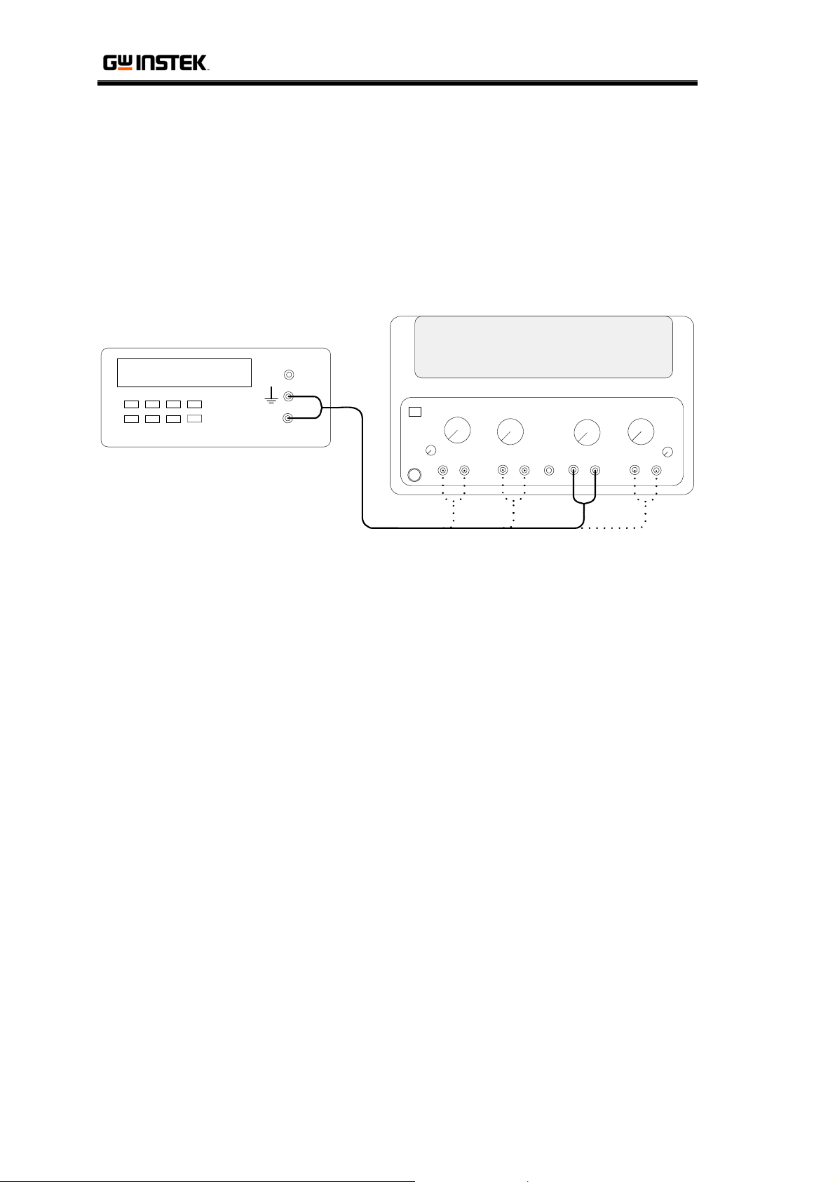
Overload Indicator Adjustment
Here we adjust Overload Indicator Accuracy.
Connection
Digital Multimeter
V
A
GPS Series
-1 +
- 3 +- 2 +- 4 +
Overload Indicator Accuracy Adjustment
1. Set the front panel according to
Default Settings
, page7, and
connect the Multimeter to CH3. Turn on the Output.
2. Turn up the Voltage Control to full.
3. Check the Multimeter readout and adjust the Overload
Indicator turns ON at the correct range. The following table
shows the adjustment point and range.
4. Switch the connection to CH4 and repeat step 2 and 3.
GPS-4303 GPS-4251 GPS-3303 GPS-2303
CH1
CH2
CH3
CH4
VR402
1.10A ~ 1.14A
N/A
2.67A ~ 2.73A
VR602
1.04A ~ 1.2A
VR402
VR402
3.22 ~ 3.28A
N/A
46
 Loading...