

Page 1
Service Manual
HiFi
Grundig Service
Hotline Deutschland...
Technik:
TV/SAT
VCR/LiveCam
HiFi/Audio
Car Audio
T elekommunikation
Fax:
Ersatzteil-Bestellannahme:
Telefon:
Fax:
...Mo.-Fr. 8.00-16.30 Uhr
0180/52318-41
0180/52318-42
0180/52318-43
0180/52318-44
0180/52318-45
0180/52318-51
0180/52318-40
0180/52318-50
SAT/TV VOLUME
V 21
TUNER
Service
Manual
V 21
Sach-Nr./Part No.
72010-755.45
CD
PHONO
POWER
HEADPHONES
Zusätzlich erforderliche
Unterlagen für den Komplettservice
Additionally required
Service Manuals for the Complete Service
Service
Manual
Sicherheit
Safety
Sach-Nr./Part No.
72010-800.00
HIFI STEREO DISCRETE AMPLIFIER V21
TAPE
VCR
BALANCE BASS TREBLE
–+ +–
DEFEAT
LEFT RIGHT
LOUDNESS
Btx * 32700 #
Sachnummer
Part Number 72010-755.45
Änderungen vorbehalten
Subject to alteration
Printed in Germany
VK233 0997
Page 2

Allgemeiner Teil / General Section V 21
Es gelten die Vorschriften und Sicherheitshinweise gemäß dem Service Manual "Sicherheit",
Sach-Nummer 72010-800.00, sowie zusätzlich
die eventuell abweichenden, landesspezifischen
Vorschriften!
Inhaltsverzeichnis
D
Seite
Allgemeiner Teil ............................ 1 - 2 … 1 - 6
Meßgeräte / Meßmittel .............................................................. 1 - 2
Technische Daten ..................................................................... 1 - 2
Ausbauhinweise ........................................................................ 1 - 3
Bedienhinweise ......................................................................... 1 - 5
Abgleich ...................................................... 2 - 1
Platinenabbildungen
und Schaltpläne .......................... 3 - 1 … 3 - 10
Verdrahtungsplan...................................................................... 3 - 1
Bauteilhinweise ......................................................................... 3 - 6
Schaltplan ................................................................................. 3 - 3
Druckplattenabbildungen .......................................................... 3 - 7
Ersatzteilliste und
Explosionszeichnung ................... 4 - 1 … 4 - 2
The regulations and safety instructions shall be
valid as provided by the "Safety" Service Manual,
part number 72010-800.00, as well as the
respective national deviations.
Table of Contents
GB
Page
General Section............................. 1 - 2 … 1 - 7
Test Equipment / Aids ............................................................... 1 - 2
Specifications ............................................................................ 1 - 2
Disassembly Instructions .......................................................... 1 - 3
Operating Hints ......................................................................... 1 - 6
Adjustment Procedures............................. 2 - 1
Layout of the PCBs
and Circuit Diagrams .................. 3 - 1 … 3 - 10
Wiring Diagram ......................................................................... 3 - 1
Note of Components ................................................................. 3 - 6
Circuit Diagram ......................................................................... 3 - 3
Layout of PCBs ......................................................................... 3 - 7
Spare Parts List and
Exploded View............................... 4 - 1 … 4 - 2
Allgemeiner Teil
Meßgeräte / Meßmittel
Digitalvoltmeter
Beachten Sie bitte das GRUNDIG Meßtechnik-Programm, das Sie
unter folgender Adresse erhalten:
GRUNDIG Instruments
Test- und Meßsysteme GmbH
Würzburger Str. 150, D-90766 Fürth/Bay
Tel. 0911/703-4118, Fax 0911/703-4130
Technische Daten
Ausgangsleistung (acc. DIN 45500)
Musikleistung 4Ω.............................................................. 2 x 95W
Sinusleistung 4Ω .............................................................. 2 x 50W
Sinusleistung 8Ω .............................................................. 2 x 40W
Eingangsempfindlichkeit/Impedanz
Line in..................................................................... 180mV / 47kΩ
Phono MM.............................................................. 1,8mV / 4,7kΩ
Klirrfaktor Sinusleistung -1dB, 8Ω, 1kHz.............................. ≤ 0,01%
Geräuschspannungsabstand ................................................. ≥ 94dB
Leistungsbandbreite............................................ < 10Hz … > 70kHz
Übertragungsbereich
Line in (-3dB)................................................... < 10Hz … > 90kHz
Phono MM............................................................. 20Hz … 30kHz
Stereo crosstalk 10kHz .......................................................... > 60dB
Dämpfungsfaktor 8Ω, 1kHz........................................................ ≥ 50
Spannungsversorgung
Betriebsspannung ............................................................... 230V~
Frequenz .......................................................................... 50/60Hz
max. Leistungsaufnahme .................................................. < 250W
Leistungsaufnahme in Standby.......................................... ca. 1W
Abmessungen und Gewicht
B x H x T ........................................................435 x 125 x 300mm
Gewicht .............................................................................. ca. 7kg
General Section
Test Equipment / Aids
Digital voltmeter
Please note the Grundig Catalog "Test and Measuring Equipment"
obtainable from:
GRUNDIG Instruments
Test- und Meßsysteme GmbH
Würzburger Str. 150, D-90766 Fürth/Bay
Tel. 0911/703-4118, Fax 0911/703-4130
Specifications
Output power (acc. DIN 45500)
Music 4Ω .......................................................................... 2 x 95W
Nominal 4Ω ...................................................................... 2 x 50W
Nominal 8Ω ...................................................................... 2 x 40W
Input sensitivity / impedance
Line in..................................................................... 180mV / 47kΩ
Phono MM.............................................................. 1.8mV / 4.7kΩ
Distortion Nom. -1dB, 8Ω, 1kHz........................................... ≤ 0.01%
Signal-to-noise ratio ............................................................... ≥ 94dB
Power bandwidth ................................................ < 10Hz … > 70kHz
Frequency response
Line in (-3dB)................................................... < 10Hz … > 90kHz
Phono MM............................................................. 20Hz … 30kHz
Stereo crosstalk 10kHz .......................................................... > 60dB
Damping factor 8Ω, 1kHz........................................................... ≥ 50
Power supply
Voltage ................................................................................ 230V~
Frequency ........................................................................ 50/60Hz
Max. power consumption .................................................. < 250W
Standby power consumption....................................... approx. 1W
Dimensions & weight
W x H x D .......................................................435 x 125 x 300mm
Weight .........................................................................approx. 7kg
1 - 2 GRUNDIG Service
Page 3
V 21 Allgemeiner Teil / General Section
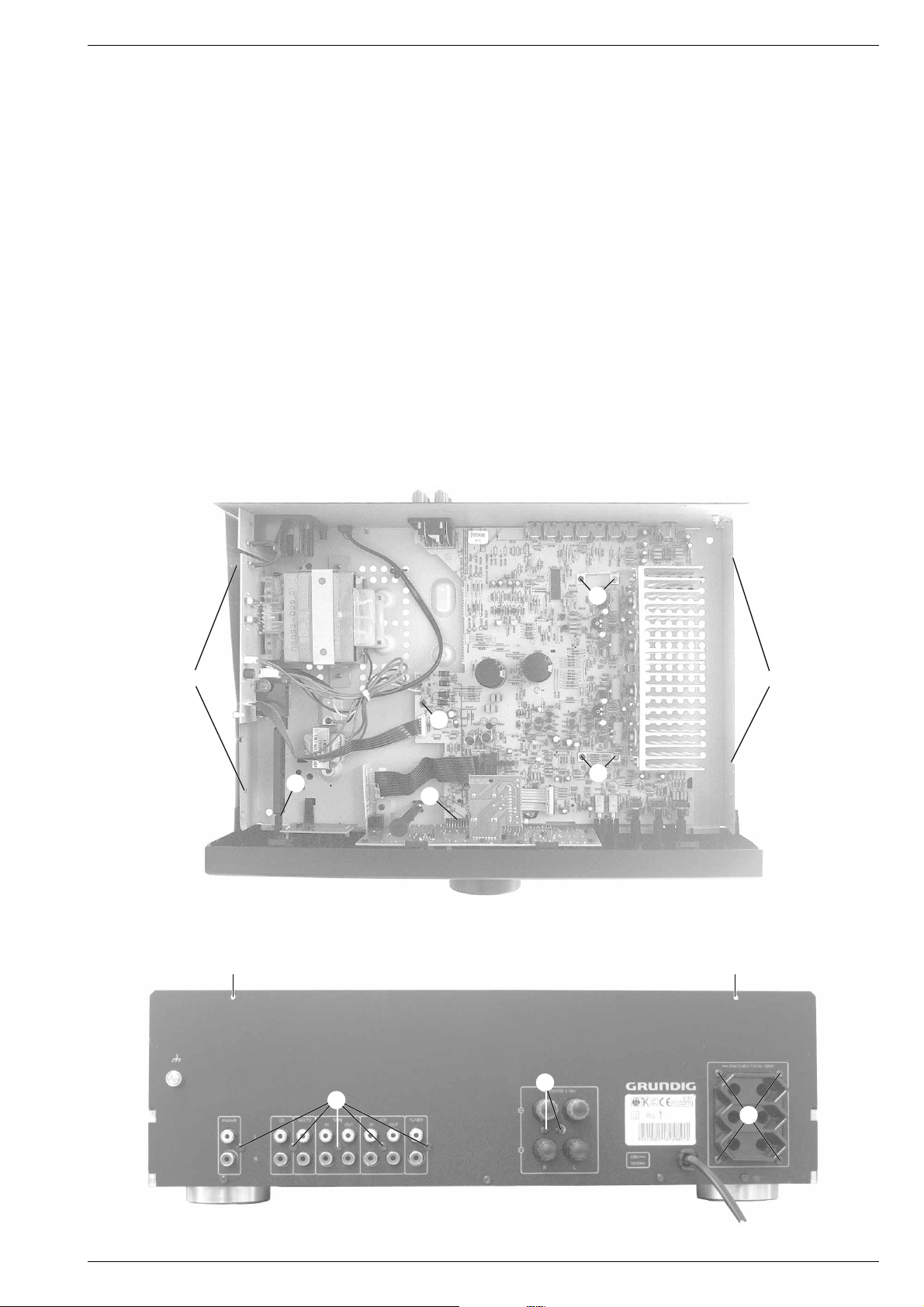
Ausbauhinweise
1. Öffnen des Gehäuses
- Die 4 Schrauben A (Fig. 1) und die 2 Schrauben B (Fig. 2)
herausschrauben.
- Den Deckel abheben.
2. Ausbau der Frontplatte
- Schraube C (Fig. 3) herausschrauben.
- Die Rastung D der Netztaste ausrasten (Fig. 1).
- Die 2 Füße E (Fig. 3) abschrauben.
- Die 3 Rastnasen F (Fig. 3) ausrasten.
- Beim Zusammenbau auf richtigen Sitz des Steckverbinders G
(Fig. 1) achten.
3. Ausbau der Hauptplatte
- Frontplatte ausbauen (Pkt. 2).
- Die 5 Schrauben H (Fig. 1) und die 7 Schrauben J (Fig. 2)
herausschrauben.
- Die Platte herausheben, dabei Steckverbinder nach Bedarf öffnen.
4. Ausbau der Trafoplatte
- Die Rastung D der Netztaste ausrasten (Fig. 1).
- Die 4 Schrauben K (Fig. 2) und die 5 Schrauben L (Fig. 3)
herausschrauben.
- Trafoplatte mit AC-Outlet-Platte herausheben, Steckverbinder nach
Bedarf öffnen.
Disassembly Instructions
1. Opening the Cabinet
- Undo the 4 srews A (Fig. 1) and the 2 screws B (Fig. 2).
- Remove the top of the cabinet.
2. Removing the Front Panel
- Undo screw C (Fig. 3).
- Disengage the mains button D (Fig. 1).
- Undo 2 feet E (Fig. 3).
- Disengage the 3 catches F (Fig. 1).
- When mounting the board, look for the correct position of connector
G (Fig. 1).
3. Removing the Main Board
- Remove the Front Panel (para 2).
- Undo the 5 screws H (Fig. 1) and the 7 screws J (Fig. 2).
- The main board can now be removed. Open connectors if
necessary.
4. Removing the Power Supply Board
- Disengage the mains button D (Fig. 1).
- Undo the 4 screws K (Fig. 2) and the 5 screws L (Fig. 3).
- Remove Power Supply Board together with the AC Outlet Board,
open connectors if necessary
H
H
D
H
G
Fig. 1
B B
AA
J
J
K
Fig. 2
GRUNDIG Service 1 - 3
Page 4
Allgemeiner Teil / General Section V 21
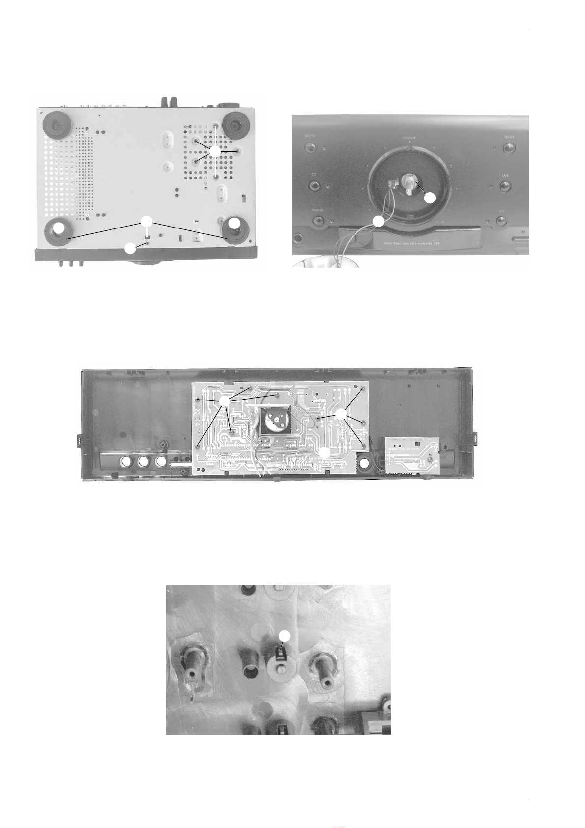
5. Ausbau der Potiplatte (Fig. 4)
- Lautstärkeknopf abziehen.
- Die Mutter M losschrauben.
- Die Potiplatte kann jetzt nach innen herausgezogen werden. Bei
Bedarf die Kabel N ablöten.
L
E
F
E
C
Fig. 3 Fig. 4
6. Zerlegen der Frontplatte (Fig. 5)
- Frontplatte ausbauen (Pkt. 2).
- Potiplatte ausbauen (Pkt. 5).
- Die 9 Schrauben O (Fig. 5) herausschrauben.
- Die Leiterplatte P kann jetzt abgenommen werden.
5. Disassembling of the Potentiometer Board (Fig. 4)
- Pull off the volume knob.
- Disengage the nut M.
- The PCB can now be removed. If necessary unsolder the wires N.
M
N
6. Disassembling of the Front Panel (Fig. 5)
- Remove the Front Board (para 2).
- Remove the potentiometer board (para 5).
- Undo 9 screws O (Fig. 5).
- The PCB P can now be removed.
7. Ausbau der Eingangswahltasten (Fig. 6)
- Frontplatte zerlegen (Pkt. 6).
- Rastnase R ausrasten und die Taste herausnehmen.
O
O
P
Fig. 5
7. Disassemble the Input Selection Buttons (Fig. 6)
- Disassemble the front panel (para 6).
- Disengage the catch R and pull out the button.
R
Fig. 6
1 - 4 GRUNDIG Service
Page 5

V 21 Allgemeiner Teil / General Section
Bedienhinweise
Dieses Kapitel enthält Auszüge aus der Bedienungsanleitung. Weitergehende Informationen entnehmen Sie bitte der gerätespezifischen Bedienungsanleitung, deren Sachnummer Sie in der
entsprechenden Ersatzteilliste finden.
Anschluß der Programmquellen
Schalten Sie zum Anschließen der Signalquellen alle beteiligten Geräte aus. Achten Sie auf den
richtigen Anschluß der Stereo-Kanäle: R: rechts (rot)
L: links (weiß).
PHONO Schließen Sie Ihren Analog-Plattenspieler an die Buchsen PHONO an.
Ist Ihr Plattenspieler mit einem getrennten Massekabel ausgestattet, klemmen Sie dieses
an die Masseschraube e an.
CD Schließen Sie Ihren CD-Spieler an die Buchsen CD an.
SAT/TV Weitere Signalquellen, wie Satellitenempfänger, Fernsehgerät, usw. schließen Sie an
den Buchsen SAT/TV an.
TAPE Verbinden Sie die LINE IN-Buchsen Ihres Kassetten-Decks, Tonbandgerätes oder digitalen
Aufnahmegeräts mit den Buchsen TAPE OUT.
Verbinden Sie die LINE OUT-Buchsen Ihres Kassetten-Decks, Tonbandgerätes oder
digitalen Aufnahmegeräts mit den Buchsen TAPE IN.
VCR
Verbinden Sie die LINE IN-Buchsen Ihres Videorecorders mit den Buchsen VCR OUT.
Verbinden Sie die LINE OUT-Buchsen Ihres Videorecorders mit den Buchsen VCR IN.
TUNER Schließen Sie Ihren TUNER and die Buchsen TUNER an.
Wollen Sie einen Satellitentuner anschließen, schließen Sie diesen an die Buchsen
SAT/TV an.
INSTALLATION
Anschließen der Lautsprecher
Um die Qualität der Wiedergabe und Leistung dieses
Gerätes voll nutzen zu können, sind entsprechend
belastbare und wertige Lautsprecherboxen
erforderlich.
Dabei sollten die Lautsprecher-boxen eine Impedanz
zwischen 4 und 16Ω aufweisen.
Die maximale Leistung gibt der Verstärker an 4Ω-
Boxen ab.
Achten Sie auf die feinen Drähte der Anschluß-Litzen.
Es dürfen keine Drähte seitlich abstehen. Diese
können Kurzschlüsse verursachen.
Wichtig: Wichtig ist auch der seitenrichtige Anschluß
der Lautsprecherboxen.
•
Der vom Hörer aus gesehen rechte Lautsprecher
muß
mit der Klemme R (rechter Kanal) verbunden sein,
der linke Lautsprecher mit der Klemme L (linker
Kanal).
• Eine Isolierung der Lautsprecherkabel
ist mit einer
Farbe oder einer Rille gekennzeichnet.
Die gekenn-
zeichnete Ader wird an die rote Klemme ange-
schlossen, die Ader ohne Kennzeichnung an die
schwarze Klemme. Achten Sie darauf, daß alle Laut-
sprecher auf diegleiche Weise angeschlossen werden.
SPEAKERS 4-16 Ω
L
R
+
–
CD
L
R
PHONO
SAT/TV TAPE
IN OUT
VCR
IN OUT
TUNER
RL
SPEAKERS 4-16
230 V
50/60 Hz
+
–
SWITCHED TOTAL 100W
AC MAINS
OUTPUTS
SPEAKERSTUNERVCRTAPESAT/TVCDPHONO
MAINS ~
RECHTS LINKS
POWER Dieser Schalter wird zum Ein- und Ausschalten des Geräts
verwendet.
HEADPHONES Hier können Sie einen handelsüblichen Stereokopfhörer mit
6,3 mm-Klinkenstecker anschließen. Die Lautstärke stellen Sie
mit dem Drehknopf VOLUME ein.
Die Lautsprecher-Ausgänge des Verstärkers werden
abgeschaltet, wenn Sie den Klinkenstecker einstecken.
Ziehen Sie den Klinkenstecker, werden die Lautsprecher
automatisch wieder eingeschaltet.
VOLUME Mit diesem Einsteller passen Sie die Lautstärke Ihren
Wünschen an.
Quellenwahl:
SAT/TV Hiermit wählen Sie den Eingang SAT/TV an.
CD Hiermit wählen Sie den Eingang CD an.
PHONO
Hiermit wählen Sie den Eingang PHONO (Plattenspieler) an.
TUNER Hiermit wählen Sie den Eingang TUNER (Radio) an.
TAPE Hiermit wählen Sie den Eingang TAPE (Kassettendeck) an.
VCR Hiermit wählen Sie den Eingang VCR (Videorecorder) an.
BEDIENELEMENTE
LOUDNESS Mit diesem Schalter können Sie die Wiedergabe bei
geringen Lautstärken dem Hörempfinden des menschlichen
Ohres anpassen.
DEFEAT
Mit diesem Schalter überbrücken Sie die klangbeeinflussende
Wirkung des BASS-, TREBLE und LOUDNESS-Einstellers.
BALANCE Hiermit beeinflussen Sie die Verteilung des Klanges
zwischen linkem und rechtem Kanal.
BASS Hiermit beeinflussen Sie den unteren Frequenzbereich.
TREBLE Hiermit beeinflussen Sie den oberen Frequenzbereich.
POWER
LOUDNESS TREBLEDEFEAT BALANCE BASS
SAT/TV, CD, PHONO
TUNER , TAPE , VCR
SAT/TV VOLUME
CD
PHONO
HIFI STEREO DISCRETE AMPLIFIER V21
TUNER
HEADPHONES
POWER
–+ +–
LEFT RIGHT
LOUDNESS
BALANCE BASS TREBLE
DEFEAT
TAPE
VCR
HEADPHONES VOLUME
Vorderseite des Verstärkers
Ein- und Ausschalten
• Schalten Sie Ihr Gerät ein, indem Sie den
Netzschalter POWER betätigen.
– Die Betriebsanzeige, eine gelbe LED in der
Mitte des Einschaltknopfes, informiert Sie über
den Schaltzustand:
Lampe brennt: EIN
Lampe brennt nicht: AUS.
– Beim Einschalten wird der Bereitschaftsbetrieb
gewählt.
–
Wollen Sie den Verstärker aktivieren, drücken
Sie eine der Eingangswahltasten am Gerät
oder auf der Fernbedienung.
– Unmittelbar nach dem Aktivieren ist der Ver-
stärker für ca. 3 Sekunden stummgeschaltet, um
störende Einschaltgeräusche zu unterdrücken.
– Wenn Sie den Verstärker aktivieren, sind auch
die
Geräte mit Spannung versorgt, die an den
Wechsel
spannungs-Ausgängen angeschlossen
sind.
• Zum Ausschalten des Verstärkers drücken Sie
die Taste POWER erneut.
– In Bereitschaftsbetrieb oder wenn Sie den
Verstärker mit dem Netzschalter POWER
ausschalten, sind weitere (über die AC-
Netzanschlüsse) angeschlossene Geräte vom
Netz getrennt.
POWER
BEDIENUNG
Wahl der Programmquellen
• Drücken Sie die entsprechende Taste am
Gerät oder auf der Fernbedienung, um eine
Programmquelle anzuwählen.
– Die gelbe LED neben der jeweiligen Taste am
Verstärker leuchtet auf.
SAT/TV VOLUME
CD
PHONO
TUNER
TAPE
VCR
Stand by-Betrieb
• Sie können den Verstärker mit der Fern-
bedienung (Taste y) in STAND BY schalten.
– Die Wechselspannungs-Ausgänge und daran
angeschlossene Geräte sind dann vollständig
vom Netz getrennt. Die gelbe LED in der Mitte
des Netz
schalters leuchtet als Bereitschafts-
anzeige weiterhin.
•
Wollen Sie die Anlage wieder einschalten,
drücken
Sie eine der Eingangswahltasten am
Gerät oder auf der Fernbedienung.
Hinweis:
Um den Stromverbrauch ungefähr
1W zu halten, wurde ein Stand-By-
Transformator in das Gerät einge-
baut. Die Auswahl dieser Option ist
eine Konsequenz der Grundig
Umweltpolitik, die sich zum Ziel
gesetzt hat, den Stromverbrauch
auf ein Minimum zu reduzieren.
VOLUME
• Regulieren Sie die Lautstärke mit dem Einsteller
VOLUME.
• Sie können diese Funktion aber auch über die
Fernbedienung, Tasten VOLUME +/–,
ausführen.
– Ein Leuchtpunkt im Drehknopf des Lautstärke-
Einstellers VOLUME zeigt die jeweilige Position
an.
MUTING
•
Drücken Sie auf der Fernbedienung die Taste a,
können Sie die Lautstärke stummschalten, um
z.
B. ein Telefongespräch entgegenzunehmen.
– Nehmen Sie während dieser Zeit Tonband-
Aufnahmen vor, beeinträchtigt die Funktion
MUTING Ihre Aufnahme nicht, da nur die
Lautsprecher abgeschaltet werden.
– Das Klicken, welches Sie hören, wenn Sie die
Taste a betätigen, rührt von den Relais her,
welche die Lautsprecher-Ausgänge
stummschalten.
– Während der Funktion MUTING blinkt die LED
im Lautstärke-Einsteller.
• Drücken Sie die Taste a erneut, beenden Sie
die Funktion MUTING.
MUTING wird auch aufgehoben, wenn Sie
die Taste VOLUME + oder eine der
Eingangswahltasten drücken.
VOLUME
KLANGEINSTELLUNG
BASS, TREBLE
• Mit den Einstellern BASS und TREBLE können
Sie das Klangbild in den Höhen und Bässen
individuell verändern.
Somit können Sie Unregelmäßigkeiten in der
Akustik des Abhörraumes kompensieren, die
von Reflektionen an glatten Wänden oder
Dämpfung durch Textilien verursacht werden.
Hinweis: Diese Funktionen sind nur ausführbar,
wenn DEFEAT ausgeschaltet ist.
BALANCE
– Für Stereo-Wiedergabe ist es wichtig, daß von
beiden Stereo-Lautsprechern im Mittel eine
gleichmäßige Schallabstrahlung erfolgt.
– Das ‘akustische Gleichgewicht’ kann durch
eine unsymmetrische Anordnung der Sitz-
gruppe, des Hörortes, verschoben werden.
Dadurch kann der Stereo-Eindruck verfälscht
werden.
• Mit dem Einsteller BALANCE können Sie in
solchen Fällen einen Ausgleich schaffen.
–+ +–
LEFT RIGHT
BALANCE BASS TREBLE
LOUDNESS
• Betätigen Sie die Taste LOUDNESS, werden
die tiefen und hohen Frequenzen etwas
angehoben, so daß der Gesamtklang auch
bei leiser Wiedergabe immer ausgeglichen
bleibt.
– Dies geschieht in Abhängigkeit von der
Stellung des Lautstärke-Einstellers. Dabei wird
der Klang dem menschlichen Gehör
angepaßt, dessen Klangempfinden von der
Lautstärke abhängt.
– Haben Sie sehr baß-starke Lautsprecher-Boxen
angeschlossen, sollten Sie die Funktion
LOUDNESS ausschalten, um eine lineare
Wiedergabe zu erreichen.
DEFEAT
• Die Funktion DEFEAT umgeht alle Klang-
abstimmungen und bringt die Musik
unverändert an die Lautsprecher.
– Das heißt, daß die Funktionen der Tasten
LOUDNESS, BASS und TREBLE den Klang
nicht mehr beeinflussen.
Hinweis: Beachten Sie hierbei, daß LOUDNESS
und DEFEAT nicht gleichzeitig aktiviert
sein können.
LOUDNESS DEFEAT
Operating Hints
This chapter contains excerpts from the operating instructions. For further particulars please refer to the appropriate user instructions the part number of which is indicated in the relevant
spare parts list.
SYSTEMFERNBEDIENUNG
Batteriewechsel
Läßt die Reichweite Ihres IR-Gebers nach oder lassen
sich einzelne Funktionen nicht mehr ausführen, sollten
Sie die Batterien auswechseln.
Verwendeter Batterietyp 2x Micro 1,5 Volt LR03,
Größe AAA. Öffnen Sie zum Batteriewechsel den
Deckel des Batteriefaches auf der Rückseite des
Gebers. Achten Sie auf die richtige Polung der
Batterien (Markierung im Batteriefach beachten).
Umwelthinweis:
Denken Sie beim Batteriewechsel daran:
Batterien sind Sondermüll.
Allgemeine Tasten
y HIFI – zum Umschalten des HiFi-Systems auf
Standby
VOLUME +/– – Zum Einstellen der Lautstärke des
Verstärkers.
a – zum Stummschalten der Lautsprecher.
REAR - SURROUND - CENTRE
INSTALL – / +
Diese Auswahl betrifft nur Dolby-ProLogic-Verstärker.
Sie dienen zur Auswahl und Änderung der
Surroundeinstellungen.
TUNER
TUNER –
Zur Auswahl des Radios und um die Komman
-
dos der Fernbedienung für die Tuner-Tasten zu aktivieren.
Zehnertastatur für Direkt-Anwahl von Stationen
$#STATION – zur Auswahl der Speicherplätze oder zur
Auswahl von Buchstaben bei Eingabe von Sendernamen.
ST– Startet die Senderabstimmung vor- oder
rückwärts oder bewegt den Cursor bei der
Sendernameneingabe.
TXT/
6
– um die angegebene Information im Display zu
ändern oder die Sendernameneingabe aufzurufen.
PTY – zur Auswahl des Programmartmodus.
CD
CD/disc –
Zur Auswahl des CD-Spielers und um die Kom-
mandos der Fernbedienung für die CD-Tasten zu aktivieren.
Zehnertastatur für Direkt-Anwahl von Titeln
; – um den CD-Spieler auf PAUSE zu stellen.
9 – um den CD-Spieler auf STOP zu stellen.
B – zum Starten der Wiedergabe.
ST– um zum nächsten/vorigen Titel zu springen
oder den Suchlauf vor- oder rückwärts zu aktivieren.
TXT/
6
–
um die angegebene Information im Display zu
ändern. (nicht verwendbar für Grundig CD-Spieler
CD21/22/23)
DISC – um bei Benutzung eines CD-Wechslers, eine
bestimmte CD auszuwählen.
TAPE
TAPE – zur Auswahl des Kassettendecks und um die
Kommandos der Fernbedienung für die TAPE-Tasten
zu aktivieren.
B – zum Starten der Wiedergabe.
9 – um das Kassettendeck auf STOP zu stellen.
; – um das Kassettendeck auf PAUSE zu stellen.
ST– schneller Rück- oder Vorlauf oder Musik-
suchlauf zum nächsten oder vorigen Titel (aus
Wiedergabe gedrückt).
AB– zur Auswahl der Abspielrichtung.
1 2
3 4 5
6 7
8 9 0
STATION TUNER
VOLUME
SAT
TV
TAPE
CD
TUNER VCR
SAT
TV
8
3
AUDIO/VIDEO RC - -URC20
by
1
E
a
P
P
P
HIFI
88
TXT/6
P
P
P
AV
TV VOLUME
–
+
CENTRE/+
SURROUND/INST.
REAR/–
$
#
2
w
DISC/PTY
TV
TV – zur Auswahl des Fernsehgerätes (wenn dieser an
den SAT/TV-Eingang angeschlossen ist).
y TV – zum Umschalten auf Standby.
– nächstes oder voriges Programm.
Damit die folgenden Funktionen vom Fernsehgerät
auch ausgeführt werden können, stellen Sie bitte
sicher, daß zuerst die Taste TV auf der
Fernbedienung gedrückt ist.
Zehnertastatur für Direkt-Anwahl von Programmen.
TXT/
6
– Auswahl von Teletext.
a – Stummschaltung der Lautsprecher.
VOLUME +/– – zur Einstellung der Lautstärke.
SAT
SAT – zur Auswahl des Satellitenempfängers (wenn
dieser an den SAT/TV-Eingang angeschlossen ist).
y SAT – zum Umschalten auf Standby.
Damit die folgenden Funktionen vom Satelliten-
empfänger auch ausgeführt werden können, stellen
Sie bitte sicher, daß zuerst die Taste SAT auf der
Fernbedienung gedrückt ist.
Zehnertastatur für Direkt-Anwahl von Programmen.
– nächstes oder voriges Programm.
VCR
VCR – zur Auswahl des Videorecorders (wenn dieser
an den VCR-Eingang angeschlossen ist).
– nächstes oder voriges Programm
.
Damit die folgenden Funktionen vom Videorecorder
auch ausgeführt werden können, stellen Sie bitte
sicher, daß zuerst die Taste VCR auf der
Fernbedienung gedrückt ist.
B – zum Starten der Wiedergabe.
9 – zum Stoppen der Aufnahme/Wiedergabe.
; – um den Videorecorder auf PAUSE zu stellen.
ST– schneller Rück– und Vorlauf.
PPPPP
P
SYSTEMFERNBEDIENUNG
Bedienung von Geräten anderer Firmen
Die zu diesem Gerät beigelegte Fernbedienung kann
neben Geräten der Unterhaltungselektronik von Grundig,
auch Fernsehgeräte, Satellitenempfänger und Video-
recorder anderer Firmen fernbedienen.
Die Fernbedienung hat die Befehle für insgesamt 5 ver-
schiedene TV-, 3 SAT-Empfänger- und 10 Video-
recorder-Fernbediensysteme gespeichert.
Einstellung des zu Ihrem Fernsehgerät passenden
Fernbediencodes
• Halten Sie die Taste TV gedrückt und drücken Sie
für 6 Sekunden eine der Tasten 1...5.
• Bitte überprüfen Sie mit den Tasten , ob Ihr
Fernsehgerät auf die Befehle der Fernbedienung
reagiert.
– Wenn das Fernsehgerät reagiert, haben Sie den
korrekten Code aktiviert.
– Sollte Ihr Fernseher nicht auf den Tastendruck
reagieren, wählen Sie bitte eine andere Einstellung.
Einstellung des zu Ihrem Satellitenempfänger
passenden Fernbediencodes
• Halten Sie die Taste SAT gedrückt und drücken Sie
für 6 Sekunden eine der Tasten 1, 2 oder 3.
•
Bitte überprüfen Sie mit
,
ob Ihr SAT-Empfänger
auf die Befehle der Fernbedienung
reagiert.
–
Sollte Ihr SAT-Empfänger nicht auf den Tastendruck
reagieren, wählen Sie bitte eine andere Einstellung.
Einstellung des zu Ihrem Videorecorder passenden
Fernbediencodes
• Halten Sie die Taste VCR gedrückt und drücken Sie
für 6 Sekunden eine der Tasten 0...9.
•
Bitte überprüfen Sie mit
,
ob Ihr Videorecorder
auf
die Befehle der Fernbedienung
reagiert.
–
Sollte der Videorecorder nicht auf den Tastendruck
reagieren, wählen Sie bitte eine andere Einstellung.
PPP
P
P
P
1 2 3 4 5 6 7 8 9
0
STATION TUNER
VOLUME
SAT
TV
TAPE
CD
TUNER VCR
SAT
TV
8
3
AUDIO/VIDEO RC - -URC20
by
1
E
a
P
P
P
HIFI
88
TXT/6
P
P
P
AV
TV VOLUME
–
+
CENTRE/+
SURROUND/INST.
REAR/–
$
#
2
w
DISC/PTY
Connecting programme sources
Before connecting any programme sources, always switch any other connected units off. In
addition, note the correct connection of the stereo channels: R: right (red)
L: left (white).
PHONO Connect your analog record player to the PHONO sockets.
If your record player is provided with a separate earth cable, connect the cable to the
earthing screw e.
CD Connect your CD player to the CD sockets.
SAT/TV Other signal sources, such as a satellite tuner, TV, etc., can be connected to the SAT/TV
sockets.
TAPE Connect the LINE IN sockets of your cassette deck, tape recorder or DAT recorder to the
sockets TAPE OUT.
Connect the LINE OUT sockets of your cassette deck, tape recorder or DAT recorder to
the sockets TAPE IN.
VCR Connect the LINE IN sockets of your VCR recorder to the sockets VCR OUT.
Connect the LINE OUT sockets of your VCR recorder to the sockets VCR IN.
TUNER Connect your TUNER to the TUNER sockets.
If you want to connect a satellite tuner, connect it to the SAT/TV sockets.
INSTALLATION
CD
L
R
PHONO SAT/TV TAPE
IN OUT
VCR
IN OUT
TUNER
RL
SPEAKERS 4-16
230 V
50/60 Hz
+
–
SWITCHED TOTAL 100W
AC MAINS
OUTPUTS
SPEAKERSTUNERVCRTAPESAT/TVCDPHONO
MAINS ~
Connecting the speakers
In order to take full advantage of your unit´s superior
play-back quality and overall performance, only
quality speakers with corresponding load ratings
should be used. Speakers should thus have an
impedance of 4 to 16Ω. Maximum amplifier output is
achieved with 4Ω speakers.
In addition, always make sure that speaker wires are
properly and tightly twisted to avoid protruding
individual wires. These can cause shorts.
Important:
Proper speaker connection is also important for quality
sound.
• As seen from the listener, the right speaker must be
connected to the right terminal (right channel) and
the left speaker to the left terminal (left channel).
•
One of the wires of a loudspeaker cable is marked,
e.g. with a colour or rib. Connect the marked wire
to the red
terminal, the non-marked wire to the
black one.
Make sure that all loudspeakers are connected in
the same way.
SPEAKERS 4-16 Ω
L
R
+
–
RIGHT LEFT
POWER For switching the amplifier on and off.
HEADPHONES
This socket is for connecting standard stereo headphones with
a 6.3 mm jack.
Volume is adjusted with the rotary VOLUME knob.
The amplifier´s speaker outputs are automatically switched
off when the headphone jack is inserted.
VOLUME This control is used for adjusting the volume.
Source selection:
SAT/TV This switch is used to select the SAT/TV input.
CD This switch is used to select the CD (Compact Disc) input.
PHONO This switch is used to select the PHONO input.
TUNER This switch is used to select the TUNER (radio) input.
TAPE This switch is used to select the TAPE (cassette deck) input.
VCR This switch is used to select the VCR (video recorder) input.
OPERATING ELEMENTS
LOUDNESS This switch is used during playback to adapt the volume
level to individual hearing sensitivity.
DEFEAT This switch is used to bypass the BASS, TREBLE and
LOUDNESS controls
BALANCE
This control is used to adjust the sound balance between the left
and right channels
BASS This is to adjust the bass tones.
TREBLE This is to adjust the high tones.
POWER
LOUDNESS TREBLEDEFEAT BALANCE BASS
SAT/TV, CD, PHONO
TUNER , TAPE , VCR
SAT/TV VOLUME
CD
PHONO
HIFI STEREO DISCRETE AMPLIFIER V21
TUNER
HEADPHONES
POWER
–+ +–
LEFT RIGHT
LOUDNESS
BALANCE BASS TREBLE
DEFEAT
TAPE
VCR
HEADPHONES VOLUME
Front of the amplifier
V 21 Allgemeiner Teil / General Section
GRUNDIG Service GRUNDIG Service
1 - 5 1 - 6
Page 6

Allgemeiner Teil / General Section V 21
R 310 R 410
Al BrBl Ar
R 333 R 332 R 432 R 433
Switching on and off
• When you want to switch your amplifier on,
press the POWER button.
– The yellow LED in the middle of the button
indicates that the unit is on:
button depressed: POWER ON
button not depressed: POWER OFF
– The standby mode will be selected when the
power is switched on.
• When you want to activate your amplifier,
simply press one of the input selection buttons
on the unit or on the remote control.
– The amplifier is muted for approximately 3
seconds when it is turned on in order to
suppress disturbing initial signal noise.
– The units connected to the AC outputs are also
provided with power when the amplifier is
activated.
• To switch off the amplifier press the POWER
button again.
– In standby mode or when you switch the
amplifier off with POWER, all auxiliary units
which are connected to the amplifier via the
AC outlets are disconnected from the power
supply.
POWER
OPERATION
Source selection
• To select a listening source, press either the
corresponding button on the unit or the
corresponding button on the remote control.
– The yellow LED next to the respective button on
the amplifier comes on.
SAT/TV VOLUME
CD
PHONO
TUNER
TAPE
VCR
Stand by
• You can switch the system to STAND BY with
the y button on the system remote control.
– This also disconnects any units connected to
the AC outputs from the power supply. Active
STAND BY mode is indicated by the yellow
LED in the middle of the POWER button.
• When you want to switch your system on
again, simply press one of the input selection
buttons on the unit or on the remote control.
Note: In order to keep power
consumption at about 1W a stand-
by transformer has been built in.
The choise for this option is a
consequence of Grundig's environ-
mental policy targeting to reduce
unnecessary power consumption.
VOLUME
• The volume can be adjusted with the rotary
VOLUME knob.
• The volume can also be controlled via the
remote control with the VOLUME +/– buttons.
– An illuminated dot in the VOLUME knob
indicates the respective adjustment position.
MUTING
• The volume can be completely muted by
pressing the a button on the remote control.
This is useful, for example, if you want to take
a telephone call and do not want to be
distracted by music, news, etc., from your
system.
– If the muting function is used when recording a
tape, this has no effect on the subsequent
recor
ding volume level as only the speakers are
muted.
– The click you hear when you press the a button
comes from the relay which mutes the
speakers.
– The LED in the volume knob blinks when the
MUTING function is active.
• The MUTING function can be deactivated by
pressing the a button again or by pressing the
VOLUME + button on the remote control or
any one of the input selection buttons.
VOLUME
SOUND CONTROL
BASS, TREBLE
• The BASS and TREBLE controllers can be used
to individually adjust the higher and lower
frequencies from the sound of your speakers.
In this way, you can compensate for
surrounding acoustic irregularities which may
be caused, for example, by sound reflection
behaviour on walls with relatively large, empty
surface areas, or "damping" caused by
furniture or other objects.
Note: These controls only function when ‘DEFEAT’
is switched off.
BALANCE
– For effective stereo playback, it is important
that the sound emanates equally from both
speakers.
– Acoustic equilibrium can be distorted by
furniture groups or the listener´s position in a
room, thus distorting the impression of stereo
sound.
• The BALANCE controller can compensate for
such distortions.
–+ +–
LEFT RIGHT
BALANCE BASS TREBLE
LOUDNESS
• Pressing the LOUDNESS button slightly
accentuates the lower and higher frequencies
which renders a more balanced overall sound
during playback at a low volume.
– Its effectiveness depends in turn on the setting
of the volume knob. The sound is thus optimally
adapted to human hearing sensitivity, which is
also dependent on the respective volume.
– If you have connected speakers which exhibit
a great deal of bass, LOUDNESS should
always remain off to achieve a more linear
acoustic pattern. In this way, you compensate
for excessive emphasis of the lower
frequencies.
DEFEAT
• The DEFEAT function bypasses all tone controls
bringing the sound unchanged to the speakers.
– This means that the influence of the
LOUDNESS, BASS and TREBLE controls is
removed from the signal path
Note: LOUDNESS and DEFEAT can not be
switched on at the same time.
LOUDNESS DEFEAT
SYSTEM REMOTE CONTROL
Changing the batteries
If the range of your infrared remote control seems to
decrease, or if certain individual functions can no longer
be carried out, you should replace the batteries.
Two micro 1.5 Volt LR03 size AAA are required. To
change the batteries, open the compartment on the
back of the remote control. Ensure that the batteries
are inserted properly (note the markings in the
compartment).
In the interest of the environment: Remember that
batteries must always be disposed of properly.
General controls
y HIFI – To switch the HIFI system to STAND BY.
VOLUME +/– – Controlling the volume of the
amplifier.
a – For muting the speakers (provided the HIFI -
TV/VCR switch is in position HIFI).
REAR - SURROUND - CENTRE
INSTALL – / +
These controls are only used for Dolby Pro Logic
amplifiers.
For selecting and adapting the different surround
modes
TUNER
TUNER– For selecting the tuner (radio) and to assign
the RC commands to tuner keys.
10-button keypad for directly selecting stations
$#STATION – For selecting stations or to select
characters in the station name input mode.
ST– To start tuning up/down or to move the
cursor in the station name input mode.
TXT/
6
– To change the information shown in the
display or to enter the station name input mode.
PTY – For selecting the programme type (PTY) mode.
CD
CD – For selecting the CD player and to assign the RC
commands to CD keys.
10-button keypad for directly selecting tracks
; – To switch the CD player to PAUSE.
9 – To switch the CD player to STOP.
B – To start and restart playback of the CD player.
ST– To select next or previous tracks on a
CD, to search forward and backward.
TXT/
6
– To change the information shown in the display.
(not useful for Grundig CD players CD21/22/23)
DISC – To enter disc selection mode when using a CD-
changer.
TAPE
TAPE – For selecting the cassette deck and to assign
the RC commands to TAPE keys.
B – To start playback.
9 – To switch the cassette deck to STOP.
; – To switch the cassette deck to PAUSE.
ST– For fast winding of the tape in forward or
reverse direction or to search for next or previous
tracks during playback.
AB– For selecting the tape travel direction.
1 2 3 4 5 6 7 8 9
0
STATION TUNER
VOLUME
SAT
TV
TAPE
CD
TUNER VCR
SAT
TV
8
3
AUDIO/VIDEO RC - -URC20
by
1
E
a
P
P
P
HIFI
88
TXT/6
P
P
P
AV
TV VOLUME
–
+
CENTRE/+
SURROUND/INST.
REAR/–
$
#
2
w
DISC/PTY
TV
TV – For selecting the TV set (when connected to the
SAT/TV input).
y TV – To switch the TV to STAND BY.
– For selecting next or previous TV stations.
To control the following functions of the TV, make
sure that you have pressed the TV key on the
remote control
10-button keypad for directly selecting stations .
TXT/
6
– For selecting teletext .
a – For muting the speakers.
TV VOLUME +/– – For controlling the volume of the TV.
SAT
SAT – For selecting the satellite receiver (when
connected to the SAT/TV input).
y SAT –
To switch the satelite receiver to STAND BY.
To control the following functions of the satellite
receiver, make sure that you have pressed the SAT
key on the remote control
10-button keypad for directly selecting stations .
– For selecting next or previous satellite
programmes.
VCR
VCR – For selecting the video recorder (when
connected to the VCR input).
–
For selecting next or previous VCR stations.
To control the following functions of the video
recorder, make sure that you have pressed the VCR
key on the remote control
B – To start playback of the video recorder.
9 – To switch the video recorder to STOP.
; – To switch the video recorder to PAUSE.
QR– Fast winding of the tape in forward or
reverse direction.
PPPPP
P
SYSTEM REMOTE CONTROL
Operation of other brands
This remote control can be used to operate also other
brands of TV’s, Satellite receivers and Video recorders.
T
he codes for these other brands have already been
put in the memory.
For TV sets you can select 5 different presets, for
Satellite receivers 3 and for Video recorders 10
different presets.
How to select the right presets?
for TV sets
• Keep the TV button pressed and press one of the
number 1...5 of the numeric keys for approx. 6
seconds.
• To control if you have selected the right code, press
e.g. one of the buttons on the remote control.
– If your TV reacts to this command you have selected
the right preset.
–
If you TV does not react, try to select another preset.
for Satellite receivers
• Keep the SAT button pressed and press number 1,
2 or 3 of the numeric keys for approx. 6 seconds.
• To control if you have selected the right code, press
e.g. one of the buttons.
– If your Satellite receiver reacts to this command you
have selected the right preset.
– If you Satellite receiver does not react, try to select
another preset.
for Video recorders
• Keep the VCR button pressed and press one of the
numeric keys (1...0) for approx. 6 seconds.
• To control if you have selected the right code, press
e.g. one of the buttons.
– If your VCR reacts to this command you have
selected the right preset.
– If you VCR does not react, try to select another
preset.
P
PPPPP
1 2 3 4 5
6 7 8 9 0
STATION TUNER
VOLUME
SAT
TV
TAPE
CD
TUNER VCR
SAT
TV
8
3
AUDIO/VIDEO RC - -URC20
by
1
E
a
P
P
P
HIFI
88
TXT/6
P
P
P
AV
TV VOLUME
–
+
CENTRE/+
SURROUND/INST.
REAR/–
$
#
2
w
DISC/PTY
Abgleichvorschriften / Adjustment Procedures V 21
D
Abgleichvorschriften
Meßgeräte: Digitalvoltmeter
Abgleich Vorbereitung Abgleichprozedur
Ruhestrom
Kein Eingangssignal. Lautstärke auf Null. Gerät mindestens 2 min warmlaufen lassen.
Linker Kanal:
Digitalvoltmeter zwischen Meßpunkte Al und Bl.
Rechter Kanal:
Digitalvoltmeter zwischen Meßpunkte Ar und Br.
Linker Kanal:
Mit R 310 auf 6,0mV ± 0,5mV einstellen.
Rechter Kanal:
Mit R 410 auf 6,0mV ± 0,5mV einstellen.
GB
Adjustment Procedures
Test equipment: Digital voltmeter
Adjustment Preperation Adjustment Procedure
Quiescent current No Input Signal. Volume to Minimum. Turn on the set for at
least 2 minutes.
Left channel:
Digitalvoltmeter between testpoints Al and Bl.
Right channel:
Digitalvoltmeter between testpoints Ar and Br.
Left channel:
Adjust with R 310 for 6.0mV ± 0.5mV.
Right channel:
Adjust with R 410 for 6.0mV ± 0.5mV.
1 - 7 2 - 1
GRUNDIG Service GRUNDIG Service
Page 7

V 21 Schaltpläne und Druckplattenabbildungen / Circuit Diagrams and Layout of PCBs V 21 Schaltpläne und Druckplattenabbildungen / Circuit Diagrams and Layout of PCBs
Schaltpläne und Druckplattenabbildungen / Circuit Diagrams and Layout of PCBs
Verdrahtungsplan / Wiring Diagram
GRUNDIG Service GRUNDIG Service
3 - 1 3 - 2
Page 8

Schaltpläne und Druckplattenabbildungen / Circuit Diagrams and Layout of PCBs V 21 Schaltpläne und Druckplattenabbildungen / Circuit Diagrams and Layout of PCBs V 21
0V
0V
0V
0V
5.0V 5.0V
-0.6V
0V
-1.2V
+28.5V
+27.8V
+27.2V
-0.1V -0.1V
-0.7V
-35.3V
-36.0V
+2.5V
-0.3V
1.0V
+1.0V
+0.8V
-0.8V
+1.0V
+0.35V
-0.35V
-1.0V
+0V
+0V
0V
0V
0V
-1.0V
-1.0V
-1.7V
-1.7V
-0.6V
GRUNDIG Service GRUNDIG Service3 - 3 3 - 4
-1.2V
+28.5V
+27.8V
+27.2V
-0.1V -0.1V
-0.7V
-35.3V
-36.0V
+2.5V
-0.3V
1.0V
+1.0V
+0.8V
-0.8V
+1.0V
+0.35V
-0.35V
-1.0V
+0V
+0V
Page 9

V 21 Schaltpläne und Druckplattenabbildungen / Circuit Diagrams and Layout of PCBs V 21 Schaltpläne und Druckplattenabbildungen / Circuit Diagrams and Layout of PCBs
+0.5V
+1.2V
+4.2V
+4.9V
+1.2V
+0.7V
0V
+0V
+0.4V
+0.7V
+36.6V
-36.6V
+5.6V
+5.0V
GRUNDIG Service GRUNDIG Service3 - 5 3 - 6
Page 10

Schaltpläne und Druckplattenabbildungen / Circuit Diagrams and Layout of PCBs V 21 Schaltpläne und Druckplattenabbildungen / Circuit Diagrams and Layout of PCBs V 21
Bedienplatte / Operating Board
Lautstärke-Platte / Volume Board
Trafo-Platte / Transformer Board
T315mA
1001
1
6001
6002
1401
5
1
2002
4
2
3
2001
1301
1011
1002
Tasten-Platte / Button Board
1004
1102
1012
T1.25AL
1101
1010
4303 303 6003.1
1103
1013
8001
T800mAL
1104
1201
5201
21
1005
1003
Kopfhörer-Platte / Headphone Board
534
GRUNDIG Service GRUNDIG Service3 - 7 3 - 8
Page 11

V 21 Schaltpläne und Druckplattenabbildungen / Circuit Diagrams and Layout of PCBs V 21 Schaltpläne und Druckplattenabbildungen / Circuit Diagrams and Layout of PCBs
Hauptplatte / Main Board
GRUNDIG Service GRUNDIG Service3 - 9 3 - 10
Page 12

Ersatzteilliste und Explosionszeichnung / Spare Parts List and Exploded View V 21
0001
0002
0003
0004
0005
0006
0007
0008
0009
0010
0011
0065
0012
0013
0014
0015
0016
0017
0018
0019
0020
0021
0022
0023
0024
0025
0027
0028
0029
0030
0031
0032
0033
0034
0035
0036
0037
0038
0039
0040
0041
0042
0044
0045
0046
0049
0050
0052
0053
0068
0066
0067
0060
0055
0054
0056
0100
0101
8000
0070
1100
1101
1101
1101
1101
1102
5000
5001
0047
0026
Ersatzteilliste und Explosionszeichnung / Spare Parts List and Exploded View
Ersatzteilliste und Explosionszeichnung / Spare Parts List and Exploded View V 21
S 59401-042.00 NETZSCHALTER/POWER SWITCH
S 8315-612-027 LOET-SI.-GR 315 MA/T
S 8315-618-002 SI 5X20 T1,25A L 250V
S 8315-616-006 FS. 800MA WIC
POS. NR. SACHNUMMER BEZEICHNUNG
POS. NO. PART NUMBER DESCRIPTION
S 213 59401-030.00 SCHALTER/SWITCH
D 514 8309-215-148 DIODE 1 N 4148 WW.
POS. NR. SACHNUMMER BEZEICHNUNG
POS. NO. PART NUMBER DESCRIPTION
S 214 59401-030.00 SCHALTER/SWITCH
S 601 75954-003.31 TAKTSCHALTER/TACT SWITCH
S 602 75954-003.31 TAKTSCHALTER/TACT SWITCH
S 603 75954-003.31 TAKTSCHALTER/TACT SWITCH
S 604 75954-003.31 TAKTSCHALTER/TACT SWITCH
D 530 8309-215-148 DIODE 1 N 4148 WW.
D 531 8309-215-104 DIODE 1 N 4002 <<< -GA
D 532 8309-215-104 DIODE 1 N 4002 <<< -GA
D 533 8309-215-104 DIODE 1 N 4002 <<< -GA
D 534 8309-215-104 DIODE 1 N 4002 <<< -GA
1011
S 605 75954-003.31 TAKTSCHALTER/TACT SWITCH
S 606 75954-003.31 TAKTSCHALTER/TACT SWITCH
S 1301
1012
D 535 8309-215-148 DIODE 1 N 4148 WW.
D 536 8309-215-045 DIODE 1N4148
D 541 8309-215-401 DIODE 1 N 5401 G GI/FAG
D 542 8309-215-401 DIODE 1 N 5401 G GI/FAG
D 543 8309-215-401 DIODE 1 N 5401 G GI/FAG
D 544 8309-215-401 DIODE 1 N 5401 G GI/FAG
V 21
1013
T 161 8303-259-550 TRANS.BC 550 C SIE/PHI
T 261 8303-259-550 TRANS.BC 550 C SIE/PHI
T 301 8303-259-560 TRANS.BC 560 C
T 302 8303-241-546 TRANS.BC 546 B
T 303 8303-241-546 TRANS.BC 546 B
T 304 8303-259-560 TRANS.BC 560 C
D 551 8309-215-148 DIODE 1 N 4148 WW.
D 552 8309-215-148 DIODE 1 N 4148 WW.
D 553 8309-215-148 DIODE 1 N 4148 WW.
D 554 8309-215-148 DIODE 1 N 4148 WW.
D 611 8309-944-411 LE DIODE TLHY 4405 BT12Z
D 612 8309-944-411 LE DIODE TLHY 4405 BT12Z
D 613 8309-944-411 LE DIODE TLHY 4405 BT12Z
D 614 8309-944-411 LE DIODE TLHY 4405 BT12Z
T 305 8303-241-546 TRANS.BC 546 B
T 306 8303-293-880 TRANS.BC 880
T 307 8303-241-546 TRANS.BC 546 B
T 308 8303-273-338 TRANS.BC 338-25
T 309 8303-273-338 TRANS.BC 338-25
T 311 8302-999-142 TRANS.TIP 142 T
T 312 8302-999-147 TRANS.TIP 147 T
T 401 8303-259-550 TRANS.BC 550 C SIE/PHI
T 402 8303-241-546 TRANS.BC 546 B
T 403 8303-241-546 TRANS.BC 546 B
D 615 8309-944-411 LE DIODE TLHY 4405 BT12Z
D 616 8309-944-411 LE DIODE TLHY 4405 BT12Z
D 617 8309-944-411 LE DIODE TLHY 4405 BT12Z
D 618 8309-215-148 DIODE 1 N 4148 WW.
D 630 8309-215-148 DIODE 1 N 4148 WW.
D 631 8309-215-148 DIODE 1 N 4148 WW.
D 701 8309-944-410 LE DIODE TLHY 4405 TFK
IC 501 8305-205-703 IC MC7805CT
IC 502 8305-112-018 IC MC78L18ACP
T 404 8303-259-560 TRANS.BC 560 C
T 406 8303-293-880 TRANS.BC 880
T 407 8303-241-546 TRANS.BC 546 B
T 408 8303-273-338 TRANS.BC 338-25
T 409 8303-272-328 TRANS.BC 328-25
T 411 8302-999-142 TRANS.TIP 142 T
T 412 8302-999-147 TRANS.TIP 147 T
IC 503 8305-112-018 IC MC78L18ACP
IC 504 8305-262-821 IC LC7821 SANYO
IC 505 8305-204-834 IC LM833N/ ELLI580 NSC
IC 702 75954-068.22 IC UP MAN MC68HC705-C4
K 601 8602-331-086 CER.RES.86/13 CST 4.0 MGW
T 461 8303-259-550 TRANS.BC 550 C SIE/PHI
T 511 8303-241-546 TRANS.BC 546 B
T 512 8303-241-546 TRANS.BC 546 B
T 513 8303-293-517 TRANS.BC 517 TID/SIE
T 551 8303-272-328 TRANS.BC 328-25
T 552 8303-272-328 TRANS.BC 328-25
T 553 8303-273-338 TRANS.BC 338-25
T 554 8303-273-338 TRANS.BC 338-25
T 562 8303-241-546 TRANS.BC 546 B
T 602 8303-205-548 TRANS BC548B
QUIESCENT CURRENT
S 8701-118-049 KSW SI B 100 OHM 5%
S 8701-118-049 KSW SI B 100 OHM 5%
S 8766-701-055 KSW SI A 180 OHM 5%
S 8766-701-055 KSW SI A 180 OHM 5%
R 318
R 323
L 335 09238-197.01 HF-DROSSEL/CHOKE COIL
L 435 09238-197.01 HF-DROSSEL/CHOKE COIL
R 300 59713-028.00 POTENTIOMETER BALANCE
R 310 8790-009-036 ESTR.S 10100 OHM/RUHESTROM/
R 317
R 326
T 603 8303-205-548 TRANS BC548B
T 611 8303-205-558 TRANS BC558B
T 612 8303-205-558 TRANS BC558B
T 613 8303-205-558 TRANS BC558B
T 614 8303-205-548 TRANS BC548B
T 615 8303-205-548 TRANS BC548B
T 616 8303-205-558 TRANS BC558B
VOLUME
HOEHEN +BASS/TREBLE+BASS
HOEHEN+BASS/TREBLE+BASS
QUIESCENT CURRENT
S 8705-278-993 MOW 0922 0,47 OHM 10%
R 330 59713-043.00 POTENTIOMETER LAUTST./
R 332
R 333 8705-278-993 MOW 0922 0,47 OHM 10%
R 400 59713-016.00 POTENTIOMETER ALPS
R 401 59713-016.00 POTENTIOMETER ALPS
R 410 8790-009-036 ESTR.S 10 100 OHM/RUHESTROM/
S 8701-118-049 KSW SI B 100 OHM 5%
S 8701-118-049 KSW SI B 100 OHM 5%
S 8766-701-063 KSW SI A 390 OHM 5%
S 8766-701-055 KSW SI A 180 OHM 5%
S 8766-701-057 KSW SI A 220 OHM 5%
S 8766-701-057 KSW SI A 220 OHM 5%
R 417
R 418
R 423
R 426
R 432 8705-278-993 MOW 0922 0,47 OHM 10%
R 433 8705-278-993 MOW 0922 0,47 OHM 10%
R 541
R 542
ÄNDERUNGEN VORBEHALTEN / SUBJECT TO ALTERATION
S 8312-003-012 RELAIS G2R-1A 12V DC
RL 2 8312-001-302 RELAIS V23037-A0002-A102
RL 1401
Btx *32700#
4 - 1
GRUNDIG Service
1
AUDIO/HIFI
POS. NR. SACHNUMMER BEZEICHNUNG
POS. NO. PART NUMBER DESCRIPTION
D 325 8309-215-148 DIODE 1 N 4148 WW.
D 398 8309-215-148 DIODE 1 N 4148 WW.
D 399 8309-215-148 DIODE 1 N 4148 WW.
D 408 8309-215-104 DIODE 1 N 4002 <<< -GA
D 409 8309-215-104 DIODE 1 N 4002 <<< -GA
D 410 8309-720-034 Z DIODE 3,3 B 0,5W
D 411 8309-215-148 DIODE 1 N 4148 WW.
D 412 8309-215-148 DIODE 1 N 4148 WW.
D 424 8309-215-148 DIODE 1 N 4148 WW.
D 425 8309-215-148 DIODE 1 N 4148 WW.
D 498 8309-215-148 DIODE 1 N 4148 WW.
D 499 8309-215-148 DIODE 1 N 4148 WW.
SACH-NR. / PART NO.: 75.7099-1051
BESTELL-NR. / ORDER NO.: G.LG 2251 SCHWARZ/BLACK
Ersatzteilliste
Spare Parts List
09 / 97
d©
75709-910.51 V 21 SCHWARZ V 21 BLACK
S 29303-452.02 NETZSTECKER-UNTERTEIL KPL. MAINS PLUG LOWER PART
S1 09626-904.00 AC-BUCHSE 3-FACH AC SOCKET 3 FOLD
S 8134-023-002 THERMOSCHALTER 100 GRAD C THERMAL SWITCH 100 DEGR.
S 09623-399.01 THERMOSCHALTER 130 GRAD C THERMAL SWITCH 100 DEGR.
POS. NR. ABB. SACHNUMMER ANZ. BEZEICHNUNG DESCRIPTION
POS. NO. FIG. PART NUMBER QTY.
0001.000 1 75954-068.12 FRONTBLENDE KPL FRONT MASK CPL.
0002.000 1 75954-068.03 LICHTLEITER LIGHT GUIDE
0003.000 1 75954-068.08 LOGO GRUNDIG LOGO GRUNDIG
0004.000 1 75954-068.02 RING RING
0005.000 1 75954-068.13 FENSTER WINDOW
0006.000 1 75954-068.04 KNOPF, FUNKTION KNOB FUNCTION
0007.000 1 75954-068.14 TASTE, LOUDNESS KEY LOUDNESS
0008.000 1 75954-068.15 TASTE, DEFFAT KEY DEFFAT
0009.000 1 75954-068.11 3 KNOPF BASS, TREBLE, BALANCE KNOB BASS, REBLE, BALANCE
0010.000 1 55301-210.00 NETZTASTE POWER KEY
0011.000 1 55301-250.00 LED-LINSE LED LENS
0014.000 1 75954-068.09 2 FUSS, VORNE FOOT FRONT
0027.000 1 59852-007.00 KOPFHOERERBUCHSE PHONE JACK
0031.000 1 09666-451.00 ZUGENTLASTUNG NETZKABEL PULL-RELIEF POWER CABLE
0033.000 1 75954-068.10 2 FUSS, HINTEN FOOT REAR
0046.000 1 55301-206.01 STOESSEL PUNCH SLIDE
0061.000
0053.000 1 55306-285.00 CLIP CLIP
0054.000 1 55306-510.00 DREHKNOPF KPL ROTARY KNOB CPL.
0059.000
0060.000
0062.000
0066.000 1 09623-449.00 3 CINCHBUCHSE 4-FACH CINCH SOCKET 4 FOLD
0067.000 1 09623-448.00 2 CINCHBUCHSE 2-FACH CINCH SOCKET 2 FOLD
0068.000 1 39612-060.04 LS-KOPFKONTAKTKLEMME LS-HEAD CONTACT CLAMP
0070.000 1 75954-068.24 IR-EMPFAENGER IR RECEIVER
0080.000 75954-068.56 FERNBEDIENUNG REMOTE CONTROL
0100.000 55306-140.00 FEDER SPRING
S1 09092-005.01 NETZTRAFO POWER TRANSFORMER
5000.000
D/GB/F/I/P/E/NL/DK/S/FIN D/GB/F/I/P/E/NL/DK/S/FIN
72010-756.00 BEDIENUNGSANLEITUNG INSTRUCTION MANUAL
72010-755.45 SERVICE MANUAL SERVICE MANUAL
S1 59430-027.01 TRAFO STAND BY TRANSFORMER (STAND BY)
S1 8290-991-275 NETZKABEL KPL GWN9.17 WF MAINS CABLE CPL GWN9.17 S
5001.000
8000.000
POS. NR. SACHNUMMER BEZEICHNUNG
S 8660-197-042 SI-KERKO.A 3300PF 20%
S 8660-197-042 SI-KERKO.A 3300PF 20%
POS. NO. PART NUMBER DESCRIPTION
2002
C 545 8410-001-568 ELKO 6800UF 50V USP (A) S
2001
C 546 8410-001-568 ELKO 6800UF 50V USP (A) S
6001 8309-215-148 DIODE 1 N 4148 WW.
6002 8309-215-148 DIODE 1 N 4148 WW.
D 308 8309-215-104 DIODE 1 N 4002 <<< -GA
Änderungen vorbehalten Printed in Germany Service Manual Sach-Nr. / Part No. 72010-755.45
Subject to alteration VK 233 0997
D 513 8309-215-148 DIODE 1 N 4148 WW.
D 309 8309-215-104 DIODE 1 N 4002 <<< -GA
D 310 8309-720-034 Z DIODE 3,3 B 0,5W
D 311 8309-215-148 DIODE 1 N 4148 WW.
D 312 8309-215-148 DIODE 1 N 4148 WW.
D 324 8309-215-148 DIODE 1 N 4148 WW.
ÄNDERUNGEN VORBEHALTEN / SUBJECT TO ALTERATION
Btx *32700#
 Loading...