

Grundig GV 400, GV 410, GV 412, GV 402, GV 430 Servise Manual
...
Service
It`s Free
Manual
SERVICE MANUAL
*
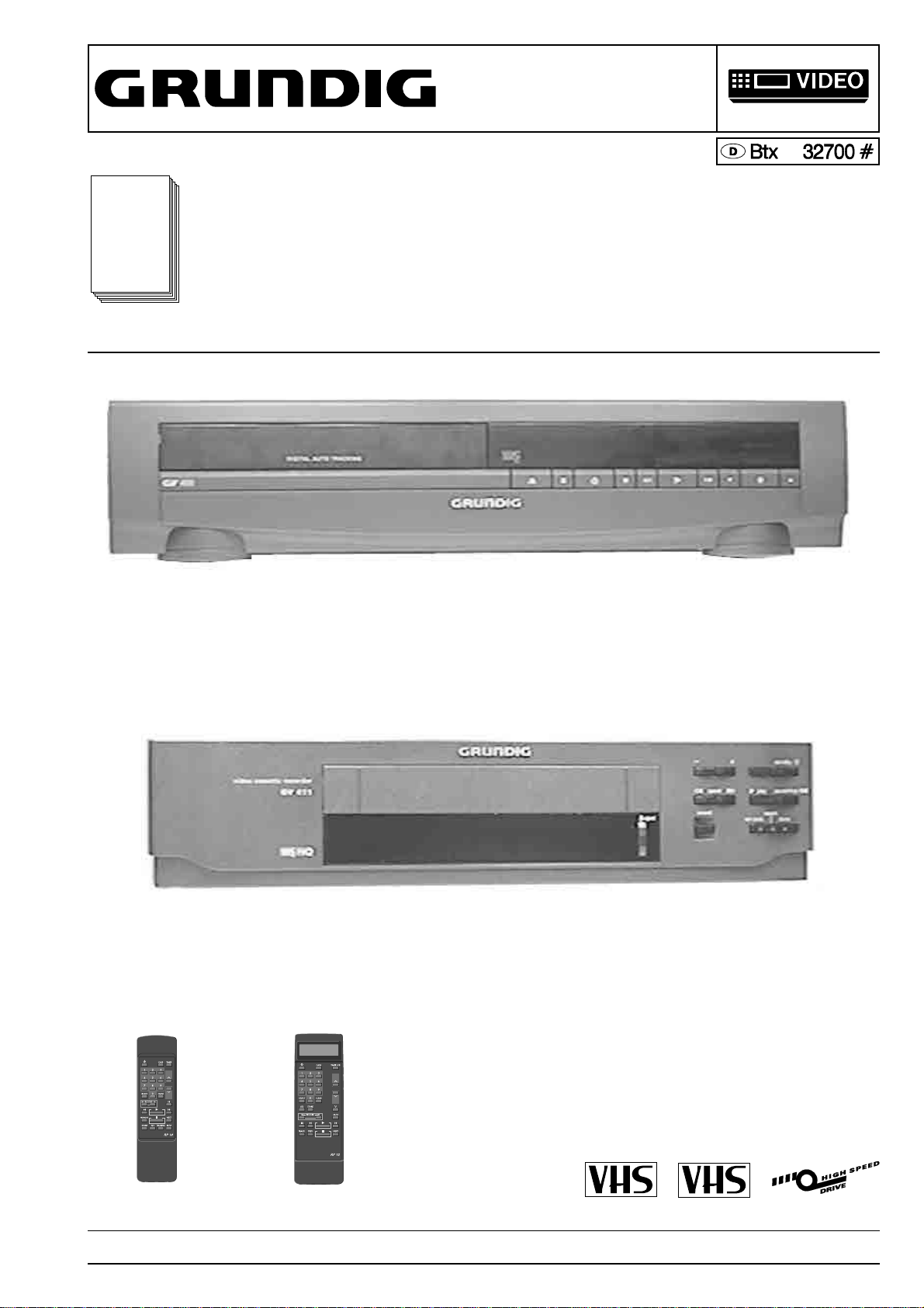
GV 400, GV 402
GV 410, GV 412
Sach-Nr./Part no.
72010-514.80
GV 400 (77400-010.51 / G.MD 0200) RP 10
GV 402 (77400-012.51 / G.MD 0900) RP 13
GV 410 (77400-110.51 / G.MD 1400) RP 10
GV 412 (77400-111.51 / G.MD 1900) RP 13
GV 430
MV 4005, MV 4105
GV 400 OST, GV 411 OST
GV 430 (77400-310.51 / G.MD 2600) RP 13
MV 4005 (77400-044.51 / M.MD 0800) RP 10
MV 4105 (77400-144.51 / M.MD 1700) RP 13
GV 400 OST (77400-013.51 / G.MD 5600) RT130
RP 10 / RT 130 RP 13 / RT 230
Änderungen vorbehalten Printed in Germany Service Manual Sach-Nr. 72010-514.80
Subject to alteration VK 222 0793 Service Manual Part No. 72010-514.80
GV 411 OST (77400-112.51 / G.MD 5700) RT 230
PAL
SECAM OST

Allgemeiner Teil / General
It`s Free
D
Inhaltsverzeichnis
Seite
Allgemeiner Teil................................. 1-1…1-38
Geräteübersicht ........................................................................... 1-3
Meßgeräte / Meßmittel................................................................. 1-4
Technische Daten ........................................................................ 1-4
Chip-Technologie......................................................................... 1-5
Sicherheitsvorschriften................................................................. 1-6
Sicherheitsbestimmungen............................................................ 1-7
Abkürzungen.............................................................................. 1-11
Bedienelemente ......................................................................... 1-12
Servicehinweise ......................................................................... 1-29
Servicetestprogramm................................................................. 1-35
Beschreibungen.................................... 2-1…2-8
Netzteil (MSM1) ........................................................................... 2-1
Chassisplatte (MFB) .................................................................... 2-1
• Ablaufsteuerung / Deckelektronik (DE) .................................... 2-1
• Empfangseinheit (FV) ............................................................. 2-4
• Video / Chroma, In / Out (VSIO) ............................................. 2-5
• Standardton / Audio Linear (AL) ............................................... 2-7
Bedieneinheit ............................................................................... 2-8
Abgleich ................................................ 3-1…3-3
Netzteil (MSM1) ........................................................................... 3-1
Chassisplatte (MFB) .................................................................... 3-1
• Ablaufsteuerung / Deckelektronik (DE) ..................................... 3-1
• Empfangseinheit (FV) .............................................................. 3-2
• Video / Chroma (VS) ................................................................ 3-2
• Standardton / Audio Linear (AL) ............................................... 3-3
Bedieneinheit ............................................................................... 3-3
GB
Table of contents
Page
General ............................................... 1-1…1-38
Video Recorder Overview ............................................................ 1-3
Test Equipment / Jigs .................................................................. 1-4
Specifications............................................................................... 1-4
Chip Technology .......................................................................... 1-5
Safety Requirements ................................................................... 1-6
Safety Standard Requirements.................................................... 1-7
Abbreviations ............................................................................. 1-11
General Notes............................................................................ 1-12
Service instructions .................................................................... 1-29
Servicetestprogram .................................................................... 1-35
Descriptions.......................................... 2-1…2-8
Power Supply (MSM1) ................................................................. 2-1
Family Board (MFB)..................................................................... 2-1
• Sequence Control / Deckelectronic (DE) .................................. 2-1
• Frontend (FV)............................................................................ 2-4
• Video / Chroma, In / Out (VSIO) ............................................... 2-5
• Standard Sound / Audio Linear (AL) ......................................... 2-7
Keyboard Control Unit.................................................................. 2-8
Adjustment Procedures....................... 3-4…3-6
Power Supply (MSM1) ................................................................. 3-4
Family Board (MFB)..................................................................... 3-4
• Sequence Control / Deckelectronic (DE) .................................. 3-4
• Frontend (FV)............................................................................ 3-5
• Video / Chroma (VS) ................................................................. 3-5
• Standard Sound / Audio Linear (AL) ......................................... 3-6
Keyboard Control Unit.................................................................. 3-6
Platinenabbildungen
und Schaltpläne ................................. 4-1…4-22
Verdrahtungsplan......................................................................... 4-1
Blockschaltplan (Analog) ............................................................. 4-2
Blockschaltplan (Digital)............................................................... 4-3
Netzteil (MSM1) ........................................................................... 4-4
Laufwerkplatte – Sensoreneinheit................................................ 4-9
Chassisplatte (MFB) .................................................................... 4-6
• Ablaufsteuerung / Deckelektronik (DE) .................................... 4-8
• Empfangseinheit (FV) ........................................................... 4-11
• Video / Chroma, In / Out (VS) ............................................... 4-12
• Standardton / Audio Linear (AL) ............................................. 4-14
Kopfverstärker (LHA) ............................................................... 4-15
Bedieneinheit (MDCG1)............................................................ 4-17
Bedieneinheit (MDCB1) ............................................................ 4-19
Oszillogramme ........................................................................... 4-21
Laufwerk ............................................ 5-1…5-10
Explosionszeichnungen
und Ersatzteilliste .............................. 6-1…6-26
Layout of the P.C.B.
and Circuit Diagrams.......................... 4-1…4-2
Wiring Diagram ............................................................................ 4-1
Block Circuit Diagram (Analog).................................................... 4-2
Block Circuit Diagram (Digital) ..................................................... 4-3
Power Supply (MSM1) ................................................................. 4-4
Tape Deck Sensor Panel ............................................................. 4-9
Family Board (MFB)..................................................................... 4-6
• Sequence Control / Deckelectronic (DE) .................................. 4-8
• Frontend (FV).......................................................................... 4-11
• Video / Chroma, In / Out (VS) ................................................. 4-12
• Standard Sound / Audio Linear (AL) ....................................... 4-14
Head Amplifier (LHA) ................................................................. 4-15
Keyboard Control Unit (MDCG1) ............................................... 4-17
Keyboard Control Unit (MDCB1)................................................ 4-19
Oscillograms .............................................................................. 4-21
Drive Mechanism............................... 5-1…5-10
Exploded Views and
Spare Parts List ................................. 6-1…6-26
1 - 2 GRUNDIG Service-Technik
Allgemeiner Teil / General
It`s Free
Geräteübersicht / Video Reocorder Overview
Allgemeiner Teil / General
Geräte-Bausteinübersicht
Table of Moduls
• Ablaufsteuerung / Sequence Control/Deckelectonic (DE) S./P 4-8
• Video/Chroma / In/Out (VSIO) S./P 4-12
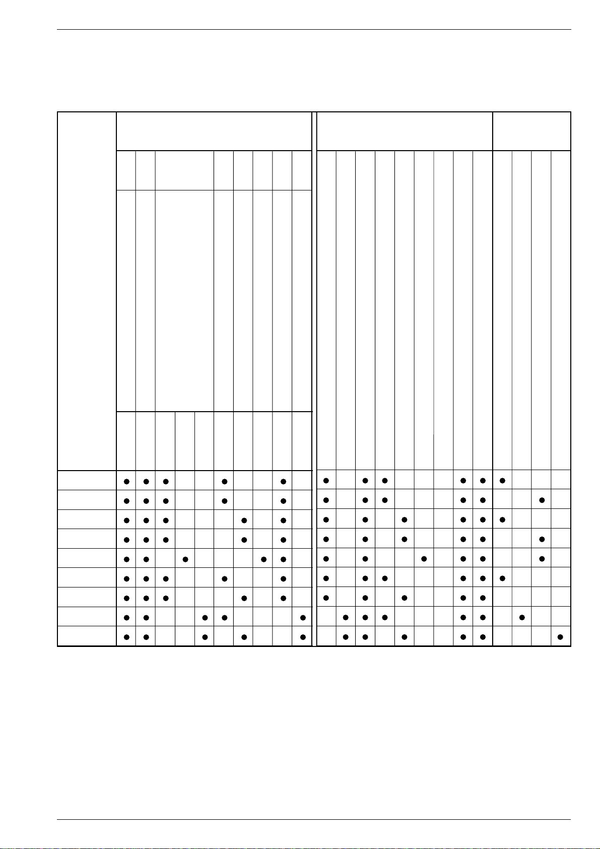
Geräte-Feature-Übersicht
Table of Features
Fernbedienung
Remote Control
GV 400
GV 402
GV 410
GV 412
GV 430
MV 4005
MV 4105
GV 400 OST
GV 411 OST
27599-003.00 Netzteil / Power Supply (MSM1) S./P 4-4
75988-001.18 Laufwerkplatte-Sensoreneinheit / Tape Deck Sensor Print S./P 4-9
27599-001.00 Chassisplatte / Family Board (MFB) S./P 4-6
27599-001.01 • Empfangseinheit / Frontend (FV) S./P 4-11
27599-001.11 • Standardton / Standard Sound - Audio Linear (AL) S./P 4-14
27599-004.00 Kopfverstärker / Head Amplifier (2-Kopf/Head) S./P 4-15
27599-004.01 Kopfverstärker / Head Amplifier (3-Kopf/Head) S./P 4-15
27599-004.02 Kopfverstärker / Head Amplifier (4-Kopf/Head) S./P 4-16
27599-002.00 Bedieneinheit / Keyboard Control Unit (MDCG1) S./P 4-17
27599-002.14 Bedieneinheit / Keyboard Control Unit (MDCB1) S./P 4-19
CCIR, B/G/H - PAL
CCIR, DK - PAL/SECAM
VST-Abstimmung/Tuning system
2-Kopf/Head
3-Kopf/Head
4-Kopf/Head (NP/LP)
VPS
6 Timer
VISS
RP10
RT130
RP13
RT230
GRUNDIG Service-Technik 1 - 3

Allgemeiner Teil / General
It`s Free
Meßgeräte / Meßmittel
Regeltrenntrafo Farbgenerator
Zweikanaloszilloskop Tongenerator
Digitalmultimeter Stabilisiertes Netzgerät
Millivoltmeter Frequenzzähler
Beachten Sie bitte das Grundig Meßtechnik-Programm, das Sie unter
folgender Adresse erhalten:
Grundig AG
Geschäftsbereich Industrieelektronik
Würzburger Str. 150
90766 Fürth/Bay.
Tel.0911/7330-0
Telefax 0911/7330-479
Sach-Nr
Testcassette.............................................................. 9.27540 - 1011
Testcassette (HiFi).................................................... 9.27540 - 1016
Bandzug-Einstellgriff und stift ................................... 75988 - 002.27
Drehmomentmesser 600gf-cm ................................. 75987 - 262.72
Adapter ..................................................................... 75987 - 262.73
Einstellschraubendreher ........................................... 75987 - 262.80
Nylonhandschuhe ....................................................... handelsüblich
Tentelometel ............................................................... handelsüblich
Diese Meßmittel können Sie über die Serviceorganisation beziehen.
Wir weisen jedoch darauf hin, daß es sich hierbei z.T. um Meßmittel
handelt, die am Markt bereits eingeführt sind.
Testcassette Sach-Nr. 9.27540-1011
• Farbtestbild mit Dropout-Einblendung
• 6,3kHz- Senkrecht-Vollspuraufzeichnung und Bezugspegel 333Hz
in dreiminütigem Wechsel.
Testcassette (HiFi) Sach-Nr. 9.27540-1016
• Farbtestbild mit Dropout-Einblendung
• Längsspur - Ton: 6,3kHz und 333Hz
• FM - Ton: 1kHz Vollpegel (± 50kHz Hub)
Test equipment / aids
Variable isolating transformer Colour generator
Dual channel oscilloscope AF Generator
Digital multimeter Stabilized power supply
Millivoltmeter Frequency counter
Please note the Grundig Catalog "Test and Measuring Equipment"
obtainable from:
Grundig AG
Geschäftsbereich Industrieelektronik
Würzburger Str. 150
90766 Fürth/Bay.
Tel.0911/7330-0
Telefax 0911/7330-479
Part no
Test cassette............................................................. 9.27540 - 1011
Test cassette (HiFi)................................................... 9.27540 - 1016
Tape tension adjustment tool - handle and - pin....... 75988 - 002.27
Torquemeter ............................................................. 75987 - 262.72
Adapter ..................................................................... 75987 - 262.73
Adjustment screw driver............................................ 75987 - 262.80
Nylon gloves ...................................................... commonly available
Tentelometer...................................................... commonly available
You can order these test equipments from the Service organization.We
refer to you that these test equipments are already obtainable on the
market.
Test cassette Part no. 9.27540-1011
• Colour test pattern with dropout recording
• 6.3kHz vertical full-track recording alternating with 333Hz reference
level every 3 minutes.
Test cassette (HiFi) Part no. 9.27540-1016
• Colour test pattern with dropout recording
• Longitudinal track sound: 6.3kHz and 333Hz
• FM sound: 1kHz full level (± 50kHz deviation)
Technische Daten
VHS-System
1/2” Video - Cassettenrecorder
Bandgeschwindigkeit .............................. 2.339cm/s (Standard play)
Aufzeichnungsgeschwindigkeit ................... 4.84m/s (Standard play)
Umspulzeit bei Vor-/Rücklauf mit E180-Cassette: .......... typisch 95s
FS-Norm
CCIR, B/G/H - PAL .................................. GV 400, GV 402, GV 410,
............................................... GV 412, GV 430, MV 4005, MV 4105
CCIR, D/K - PAL/SECAM ...................... GV 400 OST, GV 411 OST
Video
Signal / Rauschabstand .................................. ≥ 48 ±3dB (weighted)
Auflösung ........................................................................... ca. 3MHz
Ton
Frequenzgang
Standard play:.................................................... 80Hz…10kHz ≤8dB
Longplay: ............................................................. 80Hz…5kHz ≤8dB
Störabstand.......................................................... ≥ 43dB (weighted)
Gleichlaufschwankung .......................................≤ 0.5% (DIN 45507)
Netzspannung ......................................................... 220V~…240V~
Netzfrequenz ................................................................... 45…65Hz
Leistungsaufnahme
- Aufnahme .......................................................................... ca. 14W
- EE-Betrieb ......................................................................... ca. 10W
- Stand by (Modulator aus) ................................................. ca. 9,5W
Umgebungstemperatur ...........................................+10°C…+35°C
Relative Luftfeuchte.............................................................. ≤ 80%
Betriebslage ..................................................................... horizontal
Specification
VHS-System
1/2” video cassette recorder
Tape speed ............................................. 2.339cm/s (Standard play)
Head to tape speed..................................... 4.84m/s (Standard play)
Winding time or forward wind/rewind of a E180 Cassette: typically 95s
TV standard
CCIR, B/G/H - PAL .................................. GV 400, GV 402, GV 410,
............................................... GV 412, GV 430, MV 4005, MV 4105
CCIR, D/K - PAL/SECAM ...................... GV 400 OST, GV 411 OST
Video
Signal / noise ratio .......................................... ≥ 48 ±3dB (weighted)
Video resolution .......................................................... approx. 3MHz
Sound
Frequency response
Standard play:.................................................... 80Hz…10kHz ≤8dB
Longplay: ............................................................. 80Hz…5kHz ≤8dB
Signal / noise ratio ............................................... ≥ 43dB (weighted)
Wow and flutter ..................................................≤ 0.5% (DIN 45507)
Mains voltage .......................................................... 220V~…240V~
Mains frequency.............................................................. 45…65Hz
Power consumption
- Record ........................................................................ approx. 14W
- EE mode ..................................................................... approx. 10W
- Stand by mode (Modulator off) .................................. approx. 9,5W
Ambient temperature .............................................+10°C … +35°C
Relative humidity .................................................................. ≤ 80%
Operating position ........................................................... horizontal
1 - 4 GRUNDIG Service-Technik
Allgemeiner Teil / General
It`s Free
D
CHIP Technik
Aus- und Einlöten von CHIP-Bauteilen
- Verwenden Sie nur einen Niedervoltlötkolben mit Temperaturregelung.
- Die Löttemperatur sollte ca. 240 °C betragen (max. 300 °C).
- Halten Sie die Lötzeit so kurz wie möglich.
- Belassen Sie CHIP-Bauteile bis zur Bearbeitung in der Originalverpackung. Damit wird die Oxidation der Stirnkontakte vermieden.
- Berühren Sie CHIP- Bauteile nicht mit der bloßen Hand.
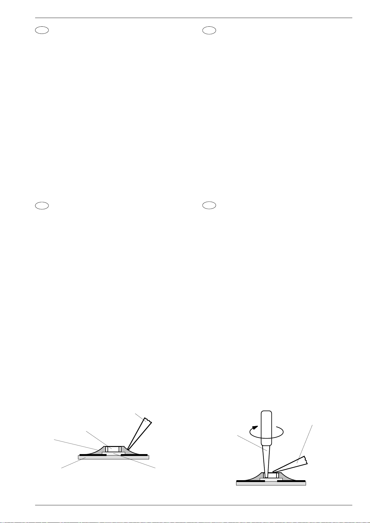
Auslöten von CHIP-Bauteilen
1. Schritt:CHIP- Lötstelle mit Sauglitze absaugen (Fig. 1).
2. Schritt: CHIP-Enden, bzw. das komplette CHIP-Bauteil erwärmen.
CHIP von der Klebung ohne Kraftaufwand abdrehen, damit
unter dem CHIP liegende Leiterbahnen nicht abgerissen
werden (Fig. 2).
Achtung! Ausgelötetes CHIP nicht wiederverwenden!
Die leitende Schicht kann ausgebrochen sein.
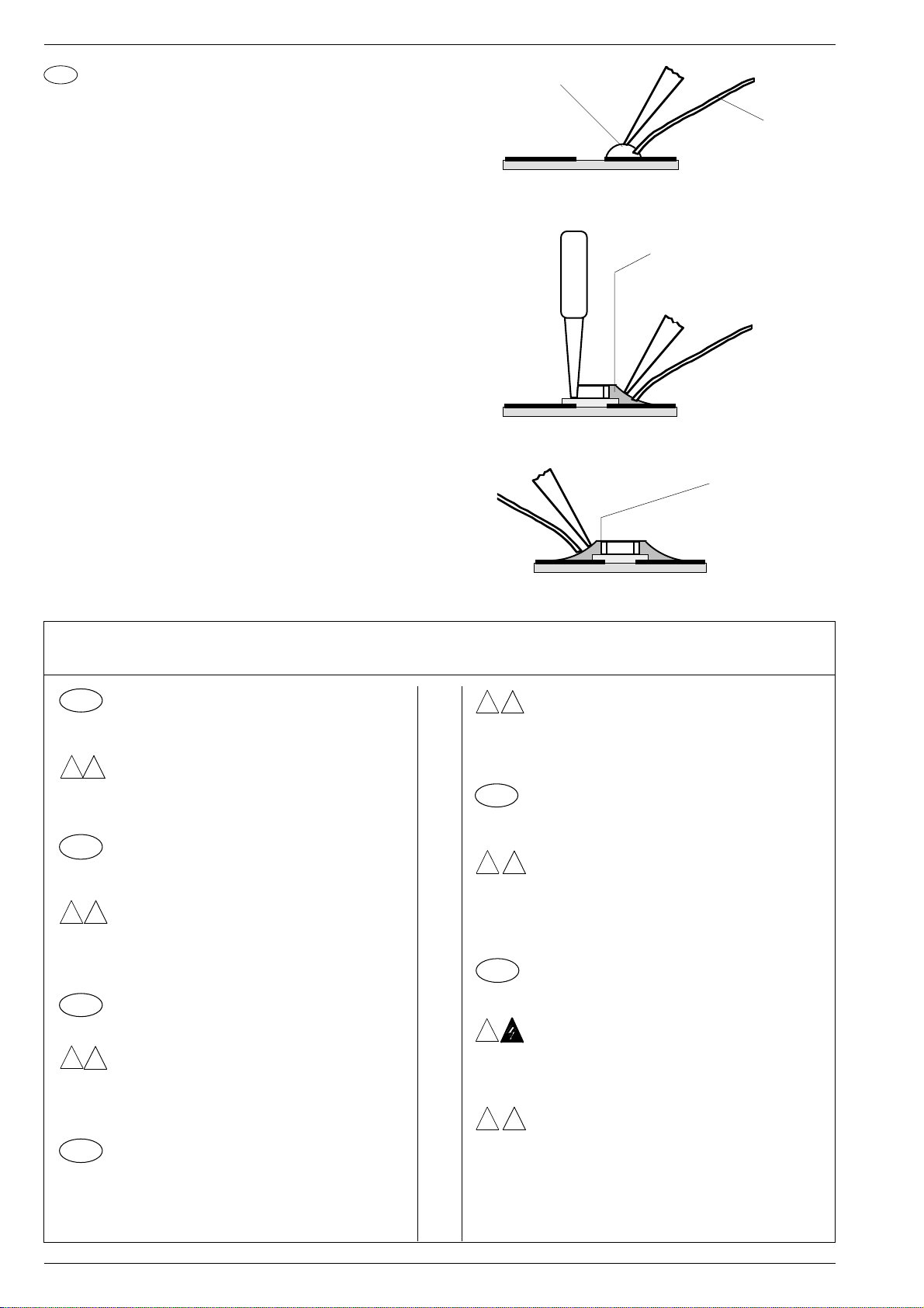
Einlöten von CHIP-Bauteilen
3. Schritt:Lötpunkt von Lötrückständen säubern.
Lötperle anbringen (Fig. 3).
4. Schritt:CHIP an der Lötstelle ansetzen, zentrieren und anlöten
(Fig. 4).
5. Schritt: Freie Seite löten. Nach dem Erkalten die erste Lötstelle
nochmals nachlöten (Fig. 5).
I
Tecnica CHIP
Saldatura e dissaldatura di componenti MOS
- Impiegare un saldatore a basso voltaggio con regolazione della
temperatura.
- Temperatura del saldatore: ca. 240 °C (valore massimo 300 °C).
- Il tempo di saldatura deve essere il più breve possibile.
- Il componente CHIP deve rimanere nell´imballaggio originale fino al
momento del suo impiego per evitare che le superfici di contatto si
ossidino.
- Non toccare i componenti CHIP con mani nude.
Dissaldatura di un CHIP
1. Aspirare i punti di saldatura del CHIP con una calza dissaldante
(Fig. 1).
2. Riscaldare le superfici di contatto del CHIP risp. te tutto il CHIP e
staccarlo con cautela. Attenzione a non esercitare for za per non
danneggiare le piste sottostanti (Fig. 2).
Attenzione! Non impiegare più il CHIP dissaldato, perchè il
corpo elettrico può presentare delle rotture.
Saldatura di un CHIP
3. Pulire il punto dai residui di saldatura. Applicare una goccia di stagno
(Fig. 3).
4. Appoggiare il CHIP sul punto di saldatura, centrarlo e quindi saldarlo
(Fig. 4).
5. Saldare la superfici di contatto libera e, dopo che questa si è
raffreddata, saldare nuovamente la superfici opposta (Fig. 5).
CHIP Technology
GB
Soldering and unsoldering of CHIP components
- Use only low-voltage soldering irons with temperature control.
- Permissible soldering temperatures are approx. 240 °C up to max.
300 °C.
- Keep the soldering period as short as possible.
- Keep the CHIP components in their original packages until they are
used to avoid oxidation of the end contacts.
- Do not touch CHIP components with bare hands.
Unsoldering of CHIP components
1. step: Clean the CHIP soldering point with a solder wick (Fig. 1).
2. step: Warm up the ends of the CHIP or the whole CHIP component
and remove the CHIP from the adhesive by turning it without
application of force so that the tracks beneath the CHIP do not
break (Fig. 2).
Attention! Do not use unsoldered CHIPS any more!
The conductive layer may be broken.
Soldering of CHIP components
3. step: Remove possible residues from the soldering point.
Then apply a solder bead (Fig. 3).
4. step: Put the CHIP onto the soldering point, then center and fix it
(Fig. 4).
5. step:Solder the free end of the CHIP and resolder the first soldering
point after it has cooled (Fig. 5).
Technologie CMS
F
Soudure des composants CMS
- Utiliser exclusivement un fer à souder à basse tension et réglage
thermique
- La température de soudure doit être de 240 OC environ
(max. 300 OC)
- L´opération doit être très brève.
- Conserver les composants CMS dans leur emballage d´origine
jusqu´au moment de leur utilisation, ceci pour éviter l´oxydation
des contacts externes.
- Ne pas toucher les composants CMS à la main nue.
Dessoudage des composants CMS
1. Aspirer la soudure du composant CMS à l'aide de la tresse à
souder (Fig. 1).
2. Chauffer légèrement les contacts externes du composant CMS
ou le composant lui-même. Retirer ce dernier avec précaution en
le tournant afin d´évìter un arrachement des circuits imprimés
situés sous le composant (Fig. 2).
Attention! Ne pas réutiliser les composants CMS, la face
conductrice pouvant être endommagée.
Soudure des composants CMS
3. Aspirer les restes de soudure sur le circuit. Poser une pointe de
soudure (Fig. 3).
4. Poser le composant CMS sur cette pointe de soudure, centrer et
souder. Maintenir le composant CMS à l´aide d´une pince (Fig. 4).
5. Effectuer la même opération pour l'autre côté. Terminer la première soudure (Fig. 5).
Chip
Composant CMS
Lötzinn
Solder
Stagno
Soudure
Estaño
Leiterplatte
P.C.B.
Piastra stampata
Circuit imprimé
Placa de circuito impreso
Fig. 1 Fig. 2
GRUNDIG Service-Technik
Lötkolbenspitze
Tip of soldering iron
Punta saldatore
Panne du fer à souder
Punto de soldator
Kleber
Adhesive
Adesivo
Adhesif
Pegamento
Pinzette
Tweezers
Pinzetta
Pince brucelle
Pinzas
Lötkolbenspitze
Tip of soldering iron
Punta saldatore
Panne du fer à souder
Punto de soldator
1 - 5
Allgemeiner Teil / General
It`s Free
E
Técnica de CHIP´s
Soldaje y desoldaje de CHIP´s
- Emplear sólo un soldador de bajo voltaje con regulación de temperatura.
- La temperatura del soldador debe ser de aprox. 240 °C
(máx. 300 °C).
- El tiempo de soldadura debe de ser lo más corto posible.
- Dejar los componentes CHIP hasta su montaje en el embalaje
original. Con ello se evita la oxidación de los contactos frontales.
- No tocar con las manos los componentes CHIP.
Desoldaje de un CHIP
Primer paso: Aspirar el estaño del punto de soldadura con un
aspirador de los tipos de pera o de resorte (Fig. 1).
Segundo paso: Calentar los extremos o todo el CHIP y girarlo con las
pinzas. No hacer fuerza para que la placa de circuito
impreso no resulte dañada. Cuidar de que las pistas
situadas debajo del CHIP no se suelten de la placa, ya
que éstas también están pegadas (Fig. 2).
Ciudado! No volver a utilizar el CHIP desoldado. La capa
eléctrica puede estar interrumpida.
Soldadura de CHIP´s
Tercer paso: Limpiar el punto de soldadura de residuos de la
soldadura anterior. Poner una gota de estaño (Fig. 3).
Cuarto paso: Colocar el CHIP sobre la gota estaño, centrarlo y
soldarlo (Fig. 4).
Quinto paso: Soldar la parte libre y, después enfriarse, soldar tam-
bién la parte opuesta (Fig. 5).
Fixierpunkt
Fixing point
Punto di fissaggio
Point de soudure
Punto de fijación
Fig. 3
Fig. 4
Lötzinn
Solder
Stagno
Soudure
Estaño
1. Lötstelle
Joint 1
Punto di saldatura 1
Point de soudure 1
Primer punto de soldadura
2. Lötstelle
Joint 2
Punto di saldatura 2
Point de soudure 2
Segundo punto de
soldadura
D
!
GB
!
I
!
F
Sicherheitsvorschriften / Safety requirements / Prescrizioni de sicurezza /
Prescriptions de sécurité / Prescripciones de seguridad
Achtung: Bei Eingriffen ins Gerät sind die Sicherheitsvorschriften nach VDE 0701 (reparaturbezogen)
bzw. VDE 0860 / IEC 65 (gerätebezogen) zu beachten!
Bauteile nach IEC- bzw. VDE-Richtlinien ! Im Ersatz-
V
D E
fall nur Teile mit gleicher Spezifikation verwenden!
MOS - Vorschriften beim Umgang mit MOS - Bautei-
len beachten!
Attention: Please observe the applicable safety re-
quirements according to VDE 0701 (concerning repairs) and VDE 0860 / IEC 65 (concerning type of
product)!
Components to IEC or VDE guidelines! Only use
V
D E
components with the same specifications for replacement!
Observe MOS components handling instructions
when servicing!
Attenzione: Osservarne le corrispondenti prescrizioni di sicurezza VDE 0701 (concernente servizio) e
VDE 0860 / IEC 65 (concernente il tipo di prodotto)!
Componenti secondo le norme VDE risp. te IEC! In
V
D E
caso di sostituzione impiegare solo componenti con le
stesse caratteristiche.
Osservare le relative prescrizioni durante, lavori con
componenti MOS!
Attention:
Prière d'observer les prescriptions de sécurité VDE
0701 (concernant les réparations) et VDE 0860 / IEC
65 (concernant le type de produit)!
Fig. 5
USA
Canada
!
E
!
U.S. &
!
!
Composants répondant aux normes VDE ou IEC. Les
V
D E
remplacer uniquement par des composants ayant les
mêmes spécifications.
Lors de la manipulation des circuits MOS, respecter les
pescriptions MOS!
Atención: Recomendamos las normas de seguridad
VDE u otras normas equivalentes, por ejemplo: VDE
0701 para reparaciones, VDE 0860 / IEC 65 para
aparatos!
Componentes que cumplen las normas VDE/IEC. En
V
D E
caso de sustitución, emplear componentes con idénticas especificaciones!
Durante la reparacion observar las normas sobre
componentes MOS!
Attention: Because of autovoltage facility this set can
be operated from AC mains from 180 - 240V, 50/60Hz.
Also observe the information given on the rear of the
set.
CAUTION-for continued protection against risk of fire
replace only with same type of fuses!
CAUTION: to reduce the risk of electric shock, do not
remove cover (or back), no user-serviceable parts
inside, refer servicing to qualified service personnel.
Components to safety guidelines (IEC/U.L.)! Only use
V
D E
com-ponents with the same specifications for replacement!
By checking the leakage current and insulation resistance ensure that the exposed parts are acceptably
insulated from the supply circuit.
Observe MOS components handling instructions
when servicing!
1 - 6 GRUNDIG Service-Technik
Allgemeiner Teil / General
It`s Free
D
Sicherheitsbestimmungen
Prescriptions de sécurité
F
D
Sicherheitsbestimmungen
Safety Standard Compliance
GB
E
Disposiciones para la seguridad
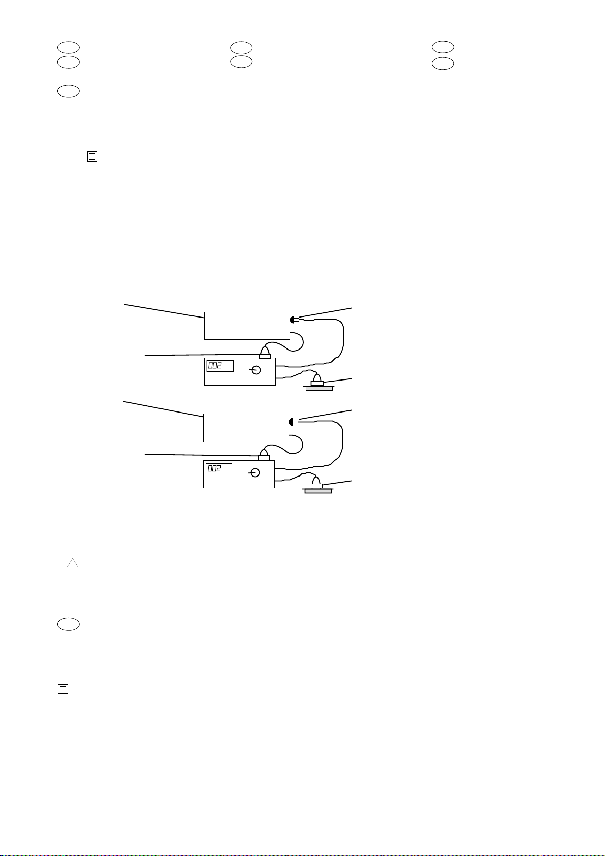
Nach Servicearbeiten ist bei Geräten der Schutzklasse II die Messung
des Isolationswiderstandes und des Ableitstromes bei eingeschaltetem Gerät nach VDE 0701 / Teil 200 bzw. der am Aufstellort geltenden
Vorschrift, durchzuführen!
Dieses Gerät entspricht der Schutzklasse II, erkennbar durch das
Symbol .
• Messen des Isolationswiderstandes nach VDE 0701.
Isolationsmesser (U
und zwischen allen Gehäuse- oder Funktionsteilen (Antenne, Buch-
= 500V-) gleichzeitig an beiden Netzpolen
Test
sen, Tasten, Zierteilen, Schrauben, usw.) aus Metall oder Metallegierungen anlegen. Fehlerfrei ist das Gerät bei einem:
R
≥ 2MΩ bei U
Isol
= 500V-
Test
Meßzeit: ≥ 1s (Fig. 1)
Anmerkung: Bei Geräten der Schutzklasse II kann durch Entladungswiderstände der Meßwert des Isolationswiderstandes konstruktionsbedingt < 2MΩ sein. In diesen Fällen ist die Ableitstrommessung
maßgebend.
Prüfling
Test item
Apparecchio in misura
Pièce d'essai
Aparato de prueba
Netzstecker des Prüflings
Mains plug of test item
Spina di rete dell´apparecchio in misura
Fiche secteur pièce d'essai
Clavija de red del aparato de prueba
Prüfling
Test item
Apparecchio in misura
Pièce d'essai
Aparato de prueba
Netzstecker des Prüflings
Mains plug of test item
Spina di rete dell´apparecchio in misura
Fiche secteur pièce d'essai
Clavija de red del aparato de prueba
MΩ
MΩ
METRATESTER 4
Fig. 1
mA
mA
METRATESTER 4
I
Norme di sicurezza
USA
Safety Instructions
• Messen des Ableitstromes nach VDE 0701.
Ableitstrommesser (U
und zwischen allen Gehäuse- oder Funktionsteilen (Antenne, Buch-
=220V≈) gleichzeitig an beiden Netzpolen
Test
sen, Tasten, Zierteilen, Schrauben, usw.) aus Metall oder Metallegierungen anlegen. Fehlerfrei ist das Gerät bei einem:
I
≤ 1mA bei U
• Wir empfehlen die Messungen mit dem METRATESTER 4 durch-
Ableit
= 220V ≈ / Meßzeit ≥ 1s (Fig. 2)
Test
zuführen. (Meßgerät zur Prüfung elektrischer Geräte nach VDE
0701).
ABB METRAWATT GmbH
Thomas-Mann-Str. 16-20
90471 Nürnberg
• Ist die Sicherheit des Gerätes nicht gegeben, weil
- eine Instandsetzung unmöglich ist,
- oder der Wunsch des Benützers besteht, die Instandsetzung nicht
durchführen zu lassen, so muß dem Betreiber die vom Gerät
ausgehende Gefahr schriftlich mitgeteilt werden.
Mit der Greifklemme alle Metallteile u. metallisierten Teile abtasten.
All metal and metallised parts must be tested with the Caliper clamp.
Con cavo provvisto di morsetto toccare tutte le parti metalliche o
metallizzate.
A l´aide d´une pince vérifier toutes les parties métalliques ou
métallisées.
Con la pinza, tocar todas las piezas metálicas o metalizadas.
Netzstecker/Mains plug/Spina di rete/Fiche secteur/Clavija de red
Fig. 2
Empfehlungen für den Servicefall
• Nur Original - Ersatzteile verwenden.
Bei Bauteilen oder Baugruppen mit der Sicherheitskennzeichnung
!
sind Original - Ersatzteile zwingend notwendig.
• Auf Sollwert der Sicherungen achten.
Zur Sicherheit beitragende Teile des Gerätes dürfen weder beschädigt noch offensichtlich ungeeignet sein.
Safety Standard Compliance
GB
After service work on a product conforming to the Safety Class II, the
insulating resistance and the leakage current with the product switched
on must be checked according to VDE 0701 or to the specification valid
at the installation location!
This product conforms to the Safety Class II, as identified by the symbol
.
• Measurement of the Insulation Resistance to VDE 0701,
Connect an Insulation Meter (U
simultaneously and between all cabinet or functional parts (antenna,
= 500V-) to both mains poles
Test
sockets, buttons, decorative parts, etc.) made from metal or metal
alloy. The product is fault free if:
R
≥ 2MΩ at U
Isol
Measuring time: ≥ 1s, (Fig. 1)
= 500V-
Test
Comment: On products conforming to the Safety Class II the Insulation Resistance can be < 2MΩ, dependent constructively on discharge resistors. In this case, the check of the leakage current is significant.
• Dies gilt besonders für Isolierungen und Isolierteile.
• Netzleitungen und Anschlußleitungen sind auf äußere Mängel vor
dem Anschluß zu prüfen. Isolation prüfen!
• Die Funktionssicherheit der Zugentlastung und von BiegeschutzTüllen ist zu prüfen.
• Thermisch belastete Lötstellen absaugen und neu löten.
• Belüftungen frei lassen.
• Measurement of the Leakage Current to VDE 0701.
Connect the Leakage Current Meter (U
poles simultaneously and between all cabinet or functional parts
= 220V≈) to both mains
Test
(antenna, sockets, buttons, screws, etc.) made from metal or metal
alloy. The product is fault free if:
I
≤ 1mA at U
Leak
Measuring time: ≥ 1s, (Fig. 2)
= 220V ≈
Test
• We recommend that the measurements be carried out using the
METRATESTER 4. (Test equipment for checking electrical pro-
ducts to VDE 0701).
ABB METRAWATT GmbH
Thomas-Mann-Str. 16-20
90471 Nürnberg
• If the safety of the product is not proved, because
- a repair and restoration is impossible
- or the request of the user is that the restoration is not to be carried
out, the operator of the product must be warned of the danger by
a written warning.
GRUNDIG Service-Technik
1 - 7

Allgemeiner Teil / General
It`s Free
Recommendation for service repairs
• With components or assemblies accompanied with the Safety
Symbol ! only original spare parts are strictly to be used.
• Use only original fuse value.
• Parts contributing to the safety of the product must not be damaged
or obviously unsuitable. This is valid especially for insulators and
insulating parts.
I
Norme di sicurezza
Successivamente ai lavori di riparazione, negli apparecchi della classe
di protezione II occorre effettuare la misura della resistenza di isolamento e della corrente di dispersione quando l’apparecchio e’acceso,
secondo le norme VDE 0701 / parte 200 e rispettivamente le norme
locali!
Questo apparecchio corrisponde alla classe di protezione II ed è
riconoscibile dal simbolo . MM
• Misura della resistenza di isolamento secondo VDE 0701
Applicare il misuratore di isolamento (tens.
poraneamente ai due poli di rete e tra tutte le parti del mobile e delle
= 500V-) contem-
prova
funzioni (antenna, prese, tasti, mascherine, viti ecc.) in metallo o in
lega metallica. L’apparecchio non presenta difetti quando:
R
≥ 2MΩ con tens.
isol
Tempo di misura: ≥ 1s (Fig. 1).
prova
= 500V-
Nota: Negli apparecchi della classe II, che per motivi costruttivi
dispongono di resistenze di dispersione, il valore di misura della
resistenza di isolamento può essere inferiore a < 2MΩ.
In questi casi è determinante la misura della corrente di dispersione.
• Misura della corrente di dispersione secondo VDE 0701
Applicare il misuratore di isolamento (tens.
raneamente ai due poli di rete e tra tutte le parti del mobile e delle
= 220V≈) contempo-
prova
funzioni ( antenna, prese, tasti, mascherine, viti ecc.) in metallo o in
lega matallica. L’apparecchio non presenta difetti quando:
I
≤ 1mA con tens.
disp.
Tempo di misura : ≥ 1s (Fig. 2)
prova
= 220V≈
• Mains leads and connecting leads should be checked for external
damage before connection. Check the insulation!
• The tension relief and bending protection bushes are to be checked
for their functional safety.
• Thermally loaded solder pads are to be sucked off and re-soldered.
Ensure that the ventilation slots are not obstructed.
• Si raccomanda di effettuare le misure con lo strumento METRATE-
STER 4 (strumento di misura per il controllo di apparecchi elettrici
secondo VDE 0701).
ABB METRAWATT GmbH
Thomas-Mann-Str. 16-20
90471 Nürnberg
• Se la sicurezza dell’apparecchio non è raggiunta, perchè
- una riparazione non è possibile
- oppure è desiderio del cliente che una riparaz. non avvenga in
questi casi si deve comunicare per iscritto all’utilizzat. la pericolosità dell’apparecchio riguardo il suo isolamento.
Raccomandazione per il servizio assistenza
• Impiegare solo componenti originali:
I componenti o i gruppi di componenti contraddistinti dall’ indicaz.
!
devono assolutamente venir sostituiti con parti originale.
• Osservare il valore nominale dei fusibili.
I componenti che concorrono alla sicurezza dell´apparecchio non
possono essere nè danneggiati nè risultare visibilmente inadatti.
Questo vale soprattutto per isolamenti e parti isolate.
• I cavi di rete e di collegamento vanno controllati prima dell’utilizzo
affinchè non presentino imperfezioni esteriori. Controllare l’isolamento.
• E´necessario controllare la sicurezza dei fermacavi e delle guaine
flessibili.
• Saldature caricate termicam. vanno rifatte.
• Lasciare libere le fessure di areazione.
Prescriptions de sécurité
F
Suite aux travaux de maintenance sur les appareils de la classe II, il
convient de mesurer la résistance d’isolement et le courant de fuite sur
l’appareil en état de marche, conformément à la norme VDE 0701 §
200, ou selon les prescriptions en vigueur sur le lieu de fonctionnement
de l’appareil!
Cet appareil est conforme aux prescriptions de sécurité classe II,
signalé par le symbole .
• Mesure de la résistance d'isolement selon VDE 0701
Brancher un appareil de mesure d’isolation (U
tanément sur les deux pôles secteur et entre toutes les parties
= 500V-) simul-
test
métalliques ou métallisées accessibles de l’appareil (antenne, embases, touches, enjoliveurs, vis, etc.).
Le fonctionnement est correct lorsque:
R
≥ 2MΩ pour une U
isol
Durée de la mesure: ≥ 1s
= 500V-
test
Observations: L’isolation des appareils de la classe II, de part leur
conception (résistances de décharge), peut être inférieure à 2MΩ,
(Fig. 1).
• Mesure du courant de fuite selon VDE 0701
Brancher un ampèremètre du courant de fuite (U
simultanément sur les deux pôles du secteur et entre toutes les
= 220V≈)
test
parties métalliques ou métallisées accessibles de l’appareil (antenne, embases, touches, enjoliveurs, vis, etc.). Le fonctionnement est
correct lorsque (Fig. 2):
I
≤ 1mA pour U
fuite
Durée de la mesure: ≥ 1s.
= 220V≈
test
Pour ces mesures, nous préconisons l´utilisation du METRATE-
STER 4 (instrument de mesure pour le contrôle d’appareils électriques conformes à la norme VDE 0701).
ABB METRAWATT GmbH
Thomas-Mann-Str. 16-20
90471 Nürnberg
• Dans le cas où la sécurité de l’appareil n´est pas assurée pour les
raisons suivantes:
- la remise en état est impossible
- l’utilisateur ne souhaîte pas la remise en état de l’appareil, l'utili-
sateur doit être informé par écrit du danger que représente l'utilisation de l’appareil.
Recommandations pour la maintenance
• Utiliser exclusivement des pièces de rechange d’origine. Les com-
posants et ensembles de composants signalés par le symbole !.
• doivent être impérativement remplacés par des pièces d’origine.
• Respecter la valeur nominale des fusibles.
• Veiller au bon état et la conformité des pièces contribuant à la
sécurité de fonctionnement de l’appareil. Ceci s’applique particulièrement aux isolements et pièces isolantes.
• Vérifier le bon état extérieur des câbles secteur et des câbles de
raccordement au point de vue isolement avant la mise sous tension.
• Vérifier le bon état des protections de gaine.
• Nettoyer les soudures avant de les renouveler.
• Dégager les voies d’aération.
1 - 8 GRUNDIG Service-Technik
E
It`s Free
Disposiciones para la seguridad
Después de operaciones de servicio en aparatos de la clase de
proteccion II, se llevará a cabo la medida de la resistencia de
aislamiento y de la corriente derivada, con el aparato conectado, de
acuerdo con VDE 0701 o de las disposiciones vigentes en el lugar de
instalación.
Este aparato corresponde a la clase de protección II, reconocible por
el sìmbolo .
• Medida de la resistencia de aislamiento según VDE 0701.
Aplicar el medidor de aislamiento (U
te, a los dos polos de red y entre todas las partes del mueble o de
= 500V-), simultáneamen-
prueba
funciones ( antena, conectores, teclas, tornillos, etc.) de metal o
aleaciones metálicas. El aparato estará libre de defectos con:
R
≥ 2MΩ con U
aisl
Tiempo de medida: ≥ 1seg.
prueba
= 500V-
Observación: En aparatos de la clase de protecciòn II, condicionado
por la construcción y por resistencias de descarga, el valor de medida
de la resistencia de aislamiento puede ser inferior a < 2MΩ.
En este caso es decisiva la medida de la corriente derivada (Fig.1).
• Medida de la corriente derivada de acuerdo con VDE 0701.
Aplicar el medidor de corriente derivada (U
neamente a los dos polos de red y entre todas las partes del mueble
= 220V≈) simultá-
prueba
o de funciones (antena, conectores, teclas, tornillos, etc.)
de metal o aleaciones metálicas. El aparato estará libre de defectos
con (Fig. 2):
I
≤ 1mA con U
deriv
Tiempo de medida: ≥ 1seg.
prueba
= 220V≈.
Allgemeiner Teil / General
• Aconsejamos llevar a cabo las medidas con el METRATESTER 4
(Instrumento de medida para la comprobación de aparatos eléctricos según VDE 0701).
ABB METRAWATT GmbH
Thomas-Mann-Str. 16-20
90471 Nürnberg
• Si no se cumple la seguridad del aparato, porque
- la puesta en orden es imposible, o
- esiste el desco del usuario de no realizarla, se ha de comunicar a
quien lo haga funcionar, por escrito, del peligro dimanante del
aparato.
Recomendaciones para caso de servicio
• Emplear sólo componentes originales.
Con componentes o grupos constructivos con el indicativo de seguridad ! son de obligada necesidad piezas de repuesto originales.
• Las partes del aparato que contribuyan a la seguridad del mismo no
deben estar deterioradas ni ser manifiestamente inadecuadas.
• Esto es especialmente válido para aislamientos o piezas aislantes.
• Los cables de red y de conexión se comprobarán, antes de conec-
tarlos, en cuanto a defectos externos. Comprobar el aislamiento.
• Se ha de comprobar la función de seguridad de la compensación de
tiro o de los manguitos de protección contra doblamientos.
• Repasar los puntos de soldadura sometidos a carga térmica.
• Mantener libres los canales aireación.
USA
Safety Instructions
U.S. & Canada
The lightning flash with arrowhead symbol, within an
equilateral triangle, is intended to alert the user to the
presence of uninsulated "dangerous voltage", within the
product´s enclosure that may be of sufficient magnitude to constitute
a risk of electric shock to persons.
The exclamation point within an equilateral triangles is
intended to alert the user to the presence of important
!
operating and maintenance (servicing) instructions in the
literature accompanying the appliance.
This product was designed and manufactured to meet strict
quality and safety standards. There are, however, some installation and operation precautions which you should be particularly
aware of.
• Read Instructions - All the safety and operating instructions
should be read before the appliance is operated.
• Retain Instructions - The safety and operating instructions should
be retained for future reference.
• Heed Warnings - All warnings on the appliance and in the operating instructions should be adhered to.
• Follow Instructions - All operating and use instructions should be
followed.
• Water and Moisture - The appliance should not be used near
water-for example, near a bathtub, washbowl, kitchen sink, laundry tub, in a wet basement, or near a swimming pool, and the like.
• Wall or Ceiling Mounting - The appliance should be mounted to
wall or ceiling only as recommended by the manufacturer.
• Ventilation - The appliance should be situated so that its location
or position does not interfere with its proper ventilation. For
example, the appliance should not be situated on a bed, sofa, rug,
or similar surface that may block the ventilation openings; or,
placed in a built - in installation, such as a bookcase or cabinet that
may impede the flow of air through the ventilation openings.
• Heat - The appliance should be situated away from heat sources
such as radiators, heat registers, stoves, or other appliances
(including amplifiers) that produce heat.
• Power Sources - The appliance should be connected to a power
supply only of the type given above or as marked on the appliance.
• Power-Cord Protection - Power-supply cords should be routed so
that they are not likely to be walked on or pinched by items placed
upon or against them, paying particular attention to cords at plugs,
convenience receptacles, and the point where they exit from the
appliance.
• Cleaning - The appliance should be cleaned only as recommended by the manufacturer.
(x1) Power Lines - An outdoor antenna should be located away from
power lines.
(x2) Outdoor Antenna Grounding - If an outside antenna is connected
to the receiver, be sure the antenna system is grounded so as to
provide some protection against voltage surges and built up static
charges. Section 810 of the National Electrical Code, ANSI / NFPA
No. 70-1984, provides information with respect to proper grounding of the mast and supporting structure, grounding of the leadin wire to an antenna discharge unit, size of grounding conductors,
location of antenna discharge unit, connection to grounding electrodes, and requirements for the grounding electrode.
• Nonuse Periods - The power cord of the appliance should be
unplugged from the outlet when left unused for a long period of
time.
• Object and Liquid Entry - Care should be taken so that objects do
not fall and liquids are not spilled into the enclosure through
openings.
• Damage Requiring Service - The appliance should be serviced by
qualified service personnel when: The power-supply cord or the
plug has been damaged; or objects have fallen,or liquid has been
spilled into the appliance; or the appliance has been exposed to
rain; or the appliance does not appear to operate normally or
exhibits a marked change in performance; or the appliance has
been dropped, or the enclosure damaged; or the batteries have
been damaged.
• Servicing - the user should not attempt to service the appliance
beyond that described in the operating instructions. All other
servicing should be referred to qualified service personnel .
Items (x1) and (x2 ) apply only to receivers or tuners.
GRUNDIG Service-Technik
1 - 9

Allgemeiner Teil / General
It`s Free
D
Behandlung von MOS - Bauelementen
Schaltungen in MOS-Technik bedürfen besonderer Vorsichtsmaßnahmen gegenüber statischer Aufladung. Statische Aufladungen können an allen hochisolierenden Kunststoffen auftreten und auf den
Menschen übertragen werden, wenn Kleidung und Schuhe aus synthetischem Material bestehen.
Schutzstrukturen an den Ein- und Ausgängen der MOS-Schaltungen
geben wegen ihrer Ansprechzeit nur begrenzte Sicherheit.
Bitte beachten Sie folgende Regeln, um Bauelemente vor Beschädigung durch statische Aufladungen zu schützen:
1. MOS-Schaltungen sollen bis zur Verarbeitung in elektrisch leitenden Verpackungen verbleiben. Keinesfalls MOS-Bauteile in Styropor oder Plastikschienen lagern oder transportieren.
2. Personen müssen sich durch Berühren eines geerdeten Gegenstandes entladen, bevor sie MOS-Bauteile anfassen.
3. MOS-Bauelemente nur am Gehäuse anfassen, ohne die Anschlüsse zu berühren.
4. Prüfung und Bearbeitung nur an geerdeten Geräten vornehmen.
5. Lösen oder kontaktieren Sie MOS-ICs in Steckfassungen nicht
unter Betriebsspannung.
6. Bei p-Kanal-MOS-Bauelementen dürfen keine positiven Spannungen (bezogen auf den Substratanschluß VSS) an die Schaltung
gelangen.
Lötvorschriften für MOS-Schaltungen:
• Nur netzgetrennte Niedervoltlötkolben verwenden.
• Maximale Lötzeit 5 Sekunden bei einer Lötkolbentemperatur von
300 °C bis 400 °C.
Handling of MOS Chip Components
GB
MOS circuits require special attention with regard to static charges.
Static charges may occur with any highly insulating plastics and can
be transferred to persons wearing clothes and shoes made of
synthetic materials.
Protective circuits on the inputs and outputs of MOS circuits give
protection to a limited extent only due to the time of reaction.
Please observe the following instructions to protect the components
against damages from static charges:
1. Keep MOS components in conductive packages until they are
used. MOS components must never be stored or transported in
Styropor materials or plastic magazines.
2.Persons have to rid themselves of electrostatic charges by
touching a grounded object before handling MOS components.
3.Take the chip by the body without touching the terminals.
4.Use only grounded instruments for testing and processing
purposes.
5.Remove or connect MOS ICs with in mounting sockets only if the
operating voltage is disconnected.
6.The circuits of p-channel MOS components must not be connected
to positive voltages (with reference to bulk VSS).
MOS Soldering Instructions
• Use only mains isolated low-voltage soldering irons.
• Maximum soldering period 5 seconds at a soldering iron temperature of 300 to 400 degrees Celsius.
I
Impiego dei componenti MOS
I circuiti in tecnica MOS necessitano di una particolare attenzione per
evitare le scariche elettrostatiche.
Tutti i materiali sintetici ad alto potere isolante possono caricar si
staticamente e queste cariche possono trasmettersi all´uomo, par
ticolarmente se scarpe o vestiti sono sintetici.
Le strutture di sicurezza sull´ingresso e sull´uscita dei circuiti MOS
hanno un´efficacia limitata a causa del loro periodo di intervento.
Per proteggere i componenti MOS dalle scariche elettrostatiche si
consigla di adottare le seguenti precauzioni:
1. Fino al momento del loro impiego, i MOS devono restare in materiale
elettricamente conduttivo. Non trasportarli o depositarli mai in listelli
di plastica o in polistirolo.
2. Le persone che maneggiano i componenti MOS devona prima
scaricar si elettrostaticamente toccando un oggetto con collegamento a massa.
3. Maneggiare i componenti MOS toccandone solo l´involucro e mai i
piedini.
4. Controlli e lavorazioni devono avvenire soltanto su apparecchi con
messa a terra.
5. Non inserire e non staccare mai gli integrati MOS dagli zoccoli
quando la tensione di alimentazione è collegata.
6. Ai componenti MOS canale P non devono giungere tensioni positive
(rif. a collegamento del substrato VSS).
Norme di taratura per gli integrati MOS:
• Impiegare solo saldatori a bassa tensione con separazione dalla
rete.
• Il tempo massimo di saldatura è di 5 sec. con una temperatura del
saldatore compresa fra 300 °C e 400 °C.
Précautions à prendre pour la manipula-
F
tion des circuits MOS
Les circuits équipés en technique MOS exigent des précautions
particulières contre les charges statiques.
Des charges statiques peuvent se creér sur toutes les matières
synthétiques à fort pouvoir isolant, elles peuvent se transmettre au
corps humain et le risque est d´autant plus important si la personne
porte des vêtements ou des chaussures en matière synthétique.
Les systèmes de protection dont sont équipées les entrées et sorties
des circuits MOS n´apportent qu´une sécurité limitée du fait de leur
temps de fonctionnement.
Afin de protéger les composants contre les charges statiques, il est
recommandé d´observer règles suivantes:
1. Les circuits MOS doivent rester placés dans un matériau conducteur
jusqu´au moment de leur utilisation. Il ne doivent en aucun cas être
stockés ou transportés dans du styropore ou sur des bandes de
plastique.
2. Les personnes travaillant sur des circuits MOS doivent au préalable
se décharger de leur charge statique en touchant un object mis à
terre.
3. Les ensembles équipés de circuits MOS doivent être saisis uniquement par leur boîtier, on ne doit pas toucher les broches de
raccordement.
4. On ne doit effectuer de contrôles et travaux que sur des appareils
mis à la terre.
5. Ne jamais retirer ou raccorder un circuit MOS sur un appareil sous
tension.
6. Les circuits MOS canal p ne doivent en aucun cas recevoir de
tensions positives (en VSS par rapport à la liaison vers le substrat).
Prescription de soudure sur les circuits MOS
• N´utiliser que des fers à souder basse tension isolés du secteur
• Temps de soudre maximum : 5 secondes pour une température
comprise entre 300 °C et 400 °C.
1 - 10 GRUNDIG Service-Technik

E
It`s Free
Tratamiento de componentes en técnica
MOS
Los circuitos contruídos en técnica MOS precisan un cuidado especial
contra las cargas estáticas.
En todos los materiales plásticos de elevado aislamiento pueden
aparecer cargas estáticas y también ser transmitidas a la personas,
especialmente cuando las ropas y zapatos son de materia sintética.
Las estructuras de protección en las entradas y salidas de los
integrados MOS, debido a su tiempo de conexión, proporcionan sólo
una limitada seguridad.
Para proteger los módulos de las descargas estáticas es aconsejable
prestar atención a las siguientes reglas:
1. Los circuitos integrados MOS deben permanecer envueltos en un
material conductor hasts el momento de su empleo. En ningún caso
se les colocará ni transportará en recepientes de styropor o guías
de plástico.
2. Las personas que trabajan con elementos MOS deben descargarse
previamente tocando un objecto puesto a tierra.
D
Abkürzungen /
Abbreviation
GB
Allgemeiner Teil / General
3. Los elementos MOS sólo deben cogerse por la cápsula, sin rozar
siquiera los terminales.
4. Pruebas y trabajos con los circuitos MOS sólo deben realizarse en
aparatos que estén puestos a tierra.
5. No extraer ni establecer contacto bajo tensión de funcionamiento de
los IC´s MOS enchufables.
6. En los componentes MOS canal-p no deben llegar tensiones
positivas (con respecto a la tensión de substrato VSS) a los
circuitos.
Prescipciones para la soldadura de los circuitos
integrados MOS:
• Utilizar únicamente soldadores de baja tensión con transformadorseparador de la red.
• Tiempo máximo de soldadura: 5 segundos con una temperatura
entre 300 y 400 °C.
+12A +12V analog +12V analog
+14/9V 14V oder 9V Versorgung 14V or 9V supply
für Capstan capstan
+14A +14V analog +14V analog
+14M1 +14V motor +14V motor
+14M2 +14V motor +14V motor
+33V +33V +33V
+5A +5,2V analog +5.2V analog
+8M2 +8V motor +8V motor
-28V -28V -28V
5V2D +5,2V digital +5.2V digital
AEH1/2 Audio Löschkopf audio erase head
AFC Automatische automatic frequency
Frequenzkontrolle control
AFV Audio von Empfangseinheit audio from Frontend
AGC Automatische Verstärkungs- automatic gain control
regelung
AL Standardton (Audio Linear) Standard Sound (Audio Linear)
AMLP Audio Mono Linear Wiedergabeaudio mono linearplayback
AMLR Audio Mono Linear Aufnahme audio mono linear record
APH Wiedergabekopf Audio audio playback head
ARH Aufnahmekopf Audio audio record head
AUDINL Audio Eingang links audio in left
AUDINR Audio Eingang rechts audio in right
AUDOUTL Audio Ausgang links audio out left
AUDOUTR Audio Ausgang rechts audio out right
BGP Burstauftastung burst gate pulse
CAP Capstan Geschwindigkeit capstan speed
CLCKD1 Clock IVC clock IVC
CREV Capstan "Reverse" capstan reverse
CROT Farbrotation chroma rotation
CSI Farb-Normkennung colour standard inform.
CSYNC Synchimpuls composite sync
CTL1/2 Kontrollimpulse control pulse sig/ref
DATD1 Daten IVC data IVC
DE Ablaufsteuerung/Deck- Sequence Control/Deckelec-
elektronik tronic
ENVC Hüllkurven Komperator envelope comparator
ESPBH Externe Wahl/Wiedergabe ext. select/playback
FFP V-Impuls / Testbild feature frame pulse
FG Capstantacho capstan tacho
FMPV FM Video-Wiedergabe fm playback video
FMR FM Aufnahmestrom fm rec current
FMRV FM Videoaufnahme fm record video signal
FTA Fädeltacho threading tacho
FV Empfangseinheit Frontend
GAER Löschoszillator Masse analog ground analog erease oscillator
GNDA Masse analog ground analog
GNDD Masse digital ground digital
GNDM1 Masse Motor 1 ground motor 1
GNDM2 Masse Motor 2 ground motor 2
HEHI Display-Heizung (HIGH) display heater (HIGH)
HELO Display-Heizung (LOW) display heater (LOW)
HP1 Kopfimpuls 1 Video head pulse 1 video
HSC Kopfauswahl head select control
I/R Init und Aufnahmesperre init/record protect
INIT Initialisierungsschalter initialisation switch
INT Interrupt interrupt
IPAL Schaltspannung bei inverse switching voltage for
I8SC112 invertierte Schalterspan- inverse switching voltage for
IPBV Schaltspannung bei inverse switching voltage for
IREC Schaltspannung bei inverse switching voltage for
LED LED für Bandende/anfang LED tape start/(end
LHA Kopfverstärker Head Amplifier
LP Longplay longplay
MAINS1/2 Netzanschluss mains connection
MEH1/2 Hauptlöschkopf main-erase-head
MDC… Bedieneinheit Keyboard Control Unit
MFB Chassisplatte Family Board
MODON Modulator ein modulator on
MSM1 Netzteil Power Supply
MSMS Pal/Secam Schalter pal/secam switch
MTA "Mute" Audio mute audio
PACO Spannung für Modulator power analog modulator
PFCO Spannung fixiert Modulator power fixed modulator
PG/FG Kopfscheibentacho head reel tacho
POR Reset bei Inbetriebnahme power on reset
PWM Pulsbreiten modulierte pulse width mod.
RECP Aufnahmeschutz record protection
REEL Kopfmotor ein head-disk motor on
REV Aufnahme Video record video
SB1 Secam Band 1 secam band 1
SCL I
SDA I2C Bus - Daten I2C bus data
SYNC CTL Sync zum Ablaufrechner ctl-sync to sequence control
TAE Bandende Erkennung tape end detector
TAS Bandanfang Erkennung tape start detector
THIO einfädeln / ausfädeln threading in/out
TMO Einfädelmotor threading motor
TMO1/2 Einfädelmotor threading motor
TRIV Trackinginfo Video tracking information video
V/H-SYNC Bild oder Zeilenimpuls frame or line-pulse
VBS Video von IO zum VS video from IO to VS
VFV Video von Empfangseinheit video from Frontend
VMCO Video zum Modulator video modulator combiunit
VSB Video von VS zum IO video from VS to IO
VS Video/Chroma Video/Chroma
IO In/Out In/Out
W/R schreiben/lesen CTL-sync write/read CTL-sync
WTL Tacho Wickelteller links tacho generator, left spindle
WTR Tacho Wickelteller rechts tacho generator, right spindle
für das Laufwerk for Deck Mechanism
Wiedergabe-Standardton playback standard sound
invertiert
nung für EURO-AV-Buchse EURO-AV-socket, contact 8
Kontakt 8
Wiedergabe Video invertiert playback video
Aufnahme invertiert record
Abstimmspannung tuning voltage
2
C Bus - Takt I2C bus clock
vom Csync from csync
GRUNDIG Service-Technik
1 - 11
Servicehinweise / Service Instructions
It`s Free
Servicehinweise
für Geräte mit dem Cassettenschacht links
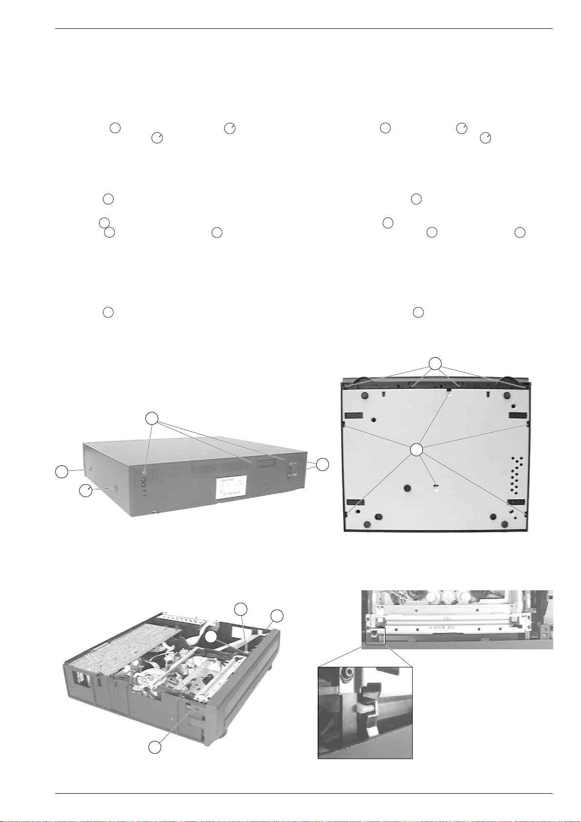
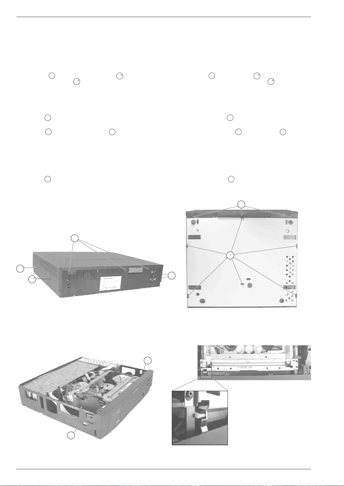
1. Entfernen der Gehäuseteile
Gehäuseoberteil
– 6 Schrauben A herausdrehen und Schraube A (Fig. 1) lösen.
Hinweis: Die Schraube A ist zur "VDE-Sicherheit" mit einer
Sicherungsscheibe an der Haube befestigt und nicht abnehmbar.
– Seitenteile des Gehäuseoberteils vorsichtig etwas auseinander-
ziehen und dabei Gehäuseoberteil ca. 3cm nach hinten schieben
und abnehmen.
Bodenblech
– Rastnasen B lösen (Fig. 2) und Bodenblech abnehmen.
Frontblende
– Schraube C (Fig. 3) herausdrehen.
– Rasthaken D (Fig. 3) sowie Rasthaken E (Fig. 2) lösen und
Frontblende abnehmen.
Hinweis zum Zusammenbau: Beim Aufstecken der Frontblende
von vorne auf das Gerät ist die Cassettenklappe so nach innen zu
drücken, daß der Hebel in die Führung (Fig. 4) der Cassettenklappe
eintaucht.
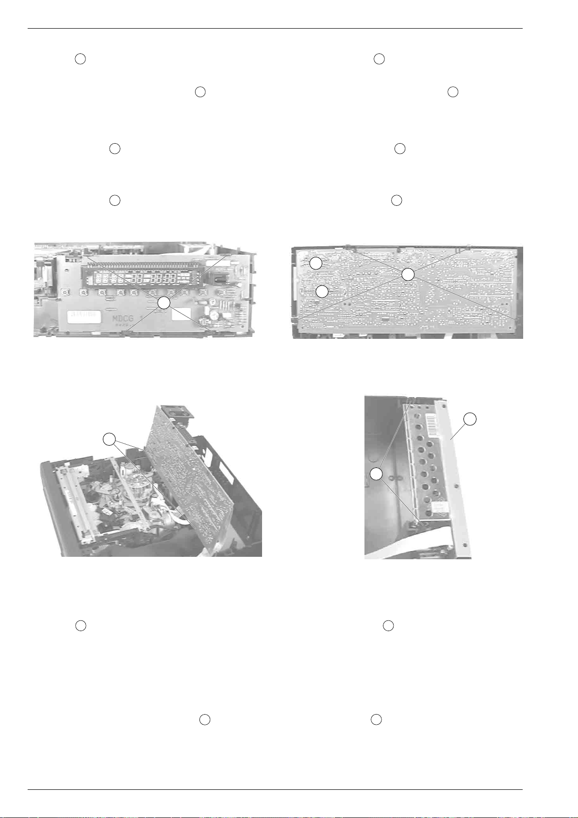
2. Bedieneinheit ausbauen
– Rastnasen F lösen (Fig. 5).
– Bedieneinheit abnehmen.
– Gegebenenfalls Steckverbindung lösen.
Service Instructions
for VCRs with the cassette compartment on the left
1. Removing the Cabinet Parts
Cabinet Upper Part
– Undo 6 screws A and loosen screw A (Fig. 1).
Note: For reasons of "VDE safety" the screw A is fastened with a
retaining washer to the upper part of the cabinet and cannot be
removed.
– Pressing the side panels carefully apart push the upper part of the
cabinet towards the rear by approx. 3cm and remove it.
Bottom Panel
– Release the locking lugs B (Fig. 2) and remove the bottom panel.
Front Panel
– Undo the screw
– Release the locking catches D (Fig.3) and the catch E (Fig. 2)
and remove the front panel.
Note: When attaching the front panel from the from to the video
recorder press the cassette lid inwards so that the lever engages
with the guide (Fig.4) of the cassette lid.
2. Removing the Keyboard Unit
– Release the locking lugs F (Fig. 5).
– Withdraw the Keyboard Unit.
– Unplug the connector if necessary.
C
E
A
B
A
A
Fig. 1
C
D
D
A
Fig. 2
GRUNDIG Service-Technik 1 - 29
D
Fig. 3
Fig. 4
Servicehinweise / Service Instructions
It`s Free
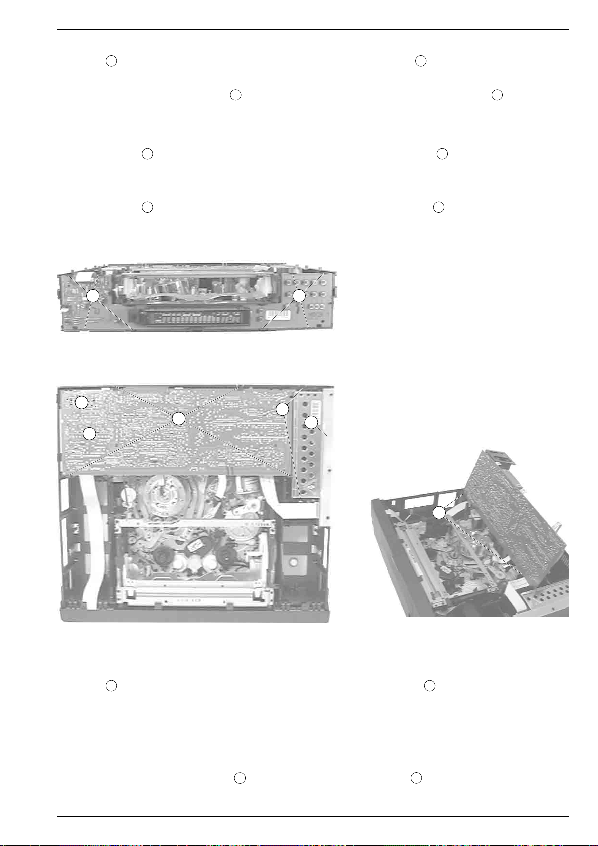
3. Chassisplatte ausbauen
– Rastnasen N öffnen und Chassisplatte herausnehmen (Fig. 6).
– Gegebenenfalls Steckverbindungen lösen.
Servicestellung:
Chassisplatte in die vorgesehenen Aussparungen O stecken (Fig. 7).
Nach Austausch: Abgleichschritte gemäß Kapitel 3 durchführen.
3.1 Tuner ausbauen
– Chassisplatte ausbauen.
– Befestigungslaschen G lösen und Tuner auslöten (Fig. 6).
– Gegebenenfalls Steckverbindung lösen.
3.2 Modulator ausbauen
– Chassisplatte ausbauen und Buchsenhalter abziehen.
– Befestigungslaschen H lösen und Modulator auslöten (Fig. 6).
– Gegebenenfalls Steckverbindung lösen.
F
3. Removing the Family Board
– Open the locking lugs N and remove the Family Board (Fig. 6).
– Unplug the connectors if necessary.
Service Position:
Insert Family Board into the cut-outs provided O (Fig. 7).
After replacement: Alignments according to chapter 3.
3.1 Removing the Tuner
– Remove the Family Board.
– Loosen the mounting hooks G and unsolder the Tuner (Fig. 6).
– Unplug the connector if necessary.
3.2 Removing the Modulator
– Remove the Family Board and pull off the socket holder.
– Loosen the mounting hooks H and unsolder the Modulator (Fig. 6).
– Unplug the connector if necessary.
H
N
G
O
Fig. 7
4. Netzteilbaustein ausbauen
– Rastnasen P ausrasten und Netzteilbaustein herausnehmen
(Fig. 8).
– Gegebenenfalls Steckverbindungen lösen.
Fig. 6Fig. 5
Q
P
Fig. 8
4. Removing the Power Supply Board
– Release the locking lugs P and take out the Power Supply Board
(Fig. 8).
– Unplug the connectors if necessary.
4.1 Reparaturen im Netzteil
Bei Reparaturen des Netzteilbausteins – Trenntrafo benutzen!
Sollen Bauteile im nicht netzgetrennten Teil des Netzteils ausgetauscht werden, müssen Sie den Abschirmdeckel abnehmen.
Nach der Reparatur darauf achten, daß der Abschirmdeckel des
Netzteilbausteins sowie der Isolationsstreifen Q (Fig. 8) angebracht sind!
1 - 30 GRUNDIG Service-Technik
4.1 Repairs within the Power Supply Unit
Use an isolating transformer when repairing the Power Supply Unit!
For replacement of components in the non-isolated circuits of the
Power Supply Unit remove the shielding cover.
On completion of the repairs take care that the shielding cover
and the isolating strip Q (Fig. 8) are refitted to the Power Supply
Unit!
Servicehinweise / Service Instructions
It`s Free
5. Kopfverstärker ausbauen
– Laufwerk ausbauen.
– Schrauben T entfernen, Steckverbindungen lösen und Kopfver-
stärker nach oben herausziehen (Fig. 11).
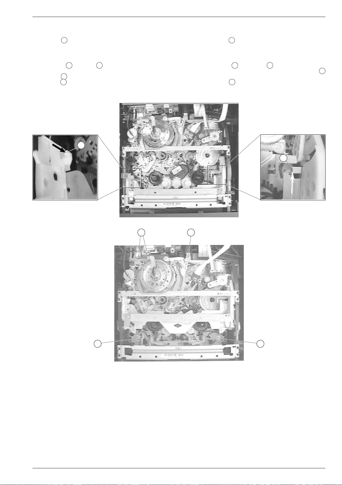
6. Laufwerkausbau
– Arretierungen R (Fig. 9) und S (Fig. 10) des Cassettenschachtes
lösen und diesen dabei so weit nach innen schieben, bis die
Schrauben U (Fig. 11) zugänglich sind.
– Schrauben U entfernen (Fig. 11) und gegebenenfalls Steckverbin-
dungen zur Elektronik lösen.
R
5. Removing the Head Amplifier
– Remove the Drive Mechanism.
– Undo the screws T, unplug the connectors and raise the Head
Amplifier to remove it (Fig. 11).
6. Removing the Drive Mechanism
– Release the locks R (Fig. 9) and S (Fig. 10) of the cassette
compartment and move it inwards to gain access to the screws
(Fig. 11).
– Undo the screws U (Fig. 11) and unplug the connectors to the
electronics if necessary.
S
U
Fig. 9
Fig. 10
UT
U
Fig. 11
U
7. Durchführen von Messungen
Bei Messungen mit dem Oszilloskop an Halbleitern sollten Sie nur
Tastköpfe mit 10:1 - Teiler verwenden. Außerdem ist zu beachten, daß
nach vorheriger Messung mit AC-Kopplung, der Koppelkondensator
des Oszilloskops aufgeladen sein kann. Durch die Entladung über das
Meßobjekt können diese Bauteile beschädigt werden.
8. Meßwerte und Oszillogramme
Bei den in den Schaltplänen und Oszillogrammen angegebenen
Meßwerten handelt es sich um Näherungswerte!
GRUNDIG Service-Technik 1 - 31
7. Carrying out Measurements
When making measurements on semi-conductors with an oscilloscope, ensure that the test probe is set to 10:1 dividing factor. Further,
please note that if the previous measurement is made on AC input, the
coupling capacitor in the oscilloscope will be charged. Discharge via
the item being checked can damage components.
8. Measured Values and Oscillograms
The measured values given in the circuit diagrams and oscillograms
are approximates!
Servicehinweise / Service Instructions
It`s Free
Servicehinweise
für Geräte mit dem Cassettenschacht in der Mitte
1. Entfernen der Gehäuseteile
Gehäuseoberteil
– 6 Schrauben A herausdrehen und Schraube A (Fig. 1) lösen.
Hinweis: Die Schraube A ist zur "VDE-Sicherheit" mit einer
Sicherungsscheibe an der Haube befestigt und nicht abnehmbar.
– Seitenteile des Gehäuseoberteils vorsichtig etwas auseinander-
ziehen und dabei Gehäuseoberteil ca. 3cm nach hinten schieben
und abnehmen.
Bodenblech
– Rastnasen B lösen (Fig. 2) und Bodenblech abnehmen.
Frontblende
– Rasthaken D (Fig. 3) sowie Rasthaken E (Fig. 2) lösen und
Frontblende abnehmen.
Hinweis zum Zusammenbau: Beim Aufstecken der Frontblende
von vorne auf das Gerät ist die Cassettenklappe so nach innen zu
drücken, daß der Hebel in die Führung (Fig. 4) der Cassettenklappe
eintaucht.
2. Bedieneinheit ausbauen
– Rastnasen F lösen (Fig. 5).
– Bedieneinheit abnehmen.
– Gegebenenfalls Steckverbindung lösen.
Service Instructions
for VCRs with the cassette compartment in the middle
1. Removing the Cabinet Parts
Cabinet Upper Part
– Undo 6 screws A and loosen screw A (Fig. 1).
Note: For reasons of "VDE safety" the screw A is fastened with a
retaining washer to the upper part of the cabinet and cannot be
removed.
– Pressing the side panels carefully apart push the upper part of the
cabinet towards the rear by approx. 3cm and remove it.
Bottom Panel
– Release the locking lugs B (Fig. 2) and remove the bottom panel.
Front Panel
– Release the locking catches D (Fig. 3) and catch E (Fig. 2) and
remove the front panel.
Note: When attaching the front panel from the front to the video
recorder press the cassette lid inwards so that the lever engages
with the guide (Fig. 4) of the cassette lid.
2. Removing the Keyboard Unit
– Release the locking lugs F (Fig. 5).
– Withdraw the Keyboard Unit.
– Unplug the connector if necessary.
E
A
B
A
A
Fig. 1
D
A
Fig. 2
D
Fig. 3 Fig. 4
1 - 32 GRUNDIG Service-Technik
Servicehinweise / Service Instructions
It`s Free
3. Chassisplatte ausbauen
– Rastnasen N öffnen und Chassisplatte herausnehmen (Fig. 6).
– Gegebenenfalls Steckverbindungen lösen.
Servicestellung:
Chassisplatte in die vorgesehenen Aussparungen O stecken (Fig. 7).
Nach Austausch: Abgleichschritte gemäß Kapitel 3 durchführen.
3.1 Tuner ausbauen
– Chassisplatte ausbauen.
– Befestigungslaschen G lösen und Tuner auslöten (Fig. 6).
– Gegebenenfalls Steckverbindung lösen.
3.2 Modulator ausbauen
– Chassisplatte ausbauen und Buchsenhalter abziehen.
– Befestigungslaschen H lösen und Modulator auslöten (Fig. 6).
– Gegebenenfalls Steckverbindung lösen.
F
3. Removing the Family Board
– Open the locking lugs N and remove the Family Board (Fig. 6).
– Unplug the connectors if necessary.
Service Position:
Insert Family Board into the cut-outs provided O (Fig. 7).
After replacement: Alignments according to chapter 3.
3.1 Removing the Tuner
– Remove the Family Board.
– Loosen the mounting hooks G and unsolder the Tuner (Fig. 6).
– Unplug the connector if necessary.
3.2 Removing the Modulator
– Remove the Family Board and pull off the socket holder.
– Loosen the mounting hooks H and unsolder the Modulator (Fig. 6).
– Unplug the connector if necessary.
F
Fig. 5
H
N
G
Fig. 6
P
Q
O
Fig. 7
4. Netzteilbaustein ausbauen
– Rastnasen P ausrasten und Netzteilbaustein herausnehmen
(Fig. 6).
– Gegebenenfalls Steckverbindungen lösen.
4.1 Reparaturen im Netzteil
Bei Reparaturen des Netzteilbausteins – Trenntrafo benutzen!
Sollen Bauteile im nicht netzgetrennten Teil des Netzteils ausgetauscht werden, müssen Sie den Abschirmdeckel abnehmen.
Nach der Reparatur darauf achten, daß der Abschirmdeckel des
Netzteilbausteins sowie der Isolationsstreifen Q (Fig. 6) angebracht sind!
GRUNDIG Service-Technik 1 - 33
4. Removing the Power Supply Board
– Release the locking lugs P and take out the Power Supply Board
(Fig. 6).
– Unplug the connectors if necessary.
4.1 Repairs within the Power Supply Unit
Use an isolating transformer when repairing the Power Supply Unit!
For replacement of components in the non-isolated circuits of the
Power Supply Unit remove the shielding cover.
On completion of the repairs take care that the shielding cover
and the isolating strip Q (Fig. 6) are refitted to the Power Supply
Unit!
Servicehinweise / Service Instructions
It`s Free
5. Kopfverstärker ausbauen
– Chassisplatte ausbauen.
– Laufwerk ausbauen.
– Schrauben T entfernen, Steckverbindungen lösen und Kopfver-
stärker nach oben herausziehen (Fig. 10).
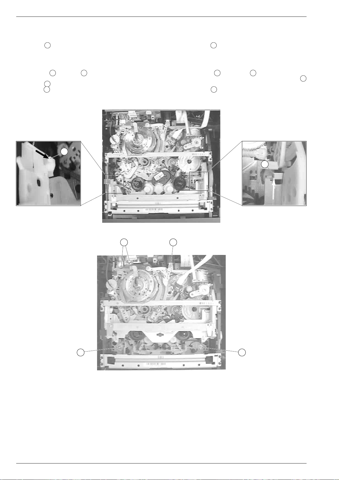
6. Laufwerkausbau
– Chassisplatte ausbauen.
– Arretierungen R (Fig. 8) und S (Fig. 9) des Cassettenschachtes
lösen und diesen dabei so weit nach innen schieben, bis die
Schrauben U (Fig. 10) zugänglich sind.
– Schrauben U entfernen (Fig. 10) und gegebenenfalls Steckverbin-
dungen zur Elektronik lösen.
R
5. Removing the Head Amplifier
– Remove the Family Board.
– Remove the Drive Mechanism.
– Undo the screws T, unplug the connectors and raise the Head
Amplifier to remove it (Fig. 10).
6. Removing the Drive Mechanism
– Remove the Family Board.
– Release the locks R (Fig. 8) and S (Fig. 9) of the cassette
compartment and move it inwards to gain access to the screws
(Fig. 10).
– Undo the screws U (Fig. 10) and unplug the connectors to the
electronics if necessary.
S
U
Fig. 8
Fig. 9
UT
U
Fig. 10
U
7. Durchführen von Messungen
Bei Messungen mit dem Oszilloskop an Halbleitern sollten Sie nur
Tastköpfe mit 10:1 - Teiler verwenden. Außerdem ist zu beachten, daß
nach vorheriger Messung mit AC-Kopplung, der Koppelkondensator
des Oszilloskops aufgeladen sein kann. Durch die Entladung über das
Meßobjekt können diese Bauteile beschädigt werden.
8. Meßwerte und Oszillogramme
Bei den in den Schaltplänen und Oszillogrammen angegebenen
Meßwerten handelt es sich um Näherungswerte!
1 - 34 GRUNDIG Service-Technik
7. Carrying out Measurements
When making measurements on semi-conductors with an oscilloscope, ensure that the test probe is set to 10:1 dividing factor. Further,
please note that if the previous measurement is made on AC input, the
coupling capacitor in the oscilloscope will be charged. Discharge via
the item being checked can damage components.
8. Measured Values and Oscillograms
The measured values given in the circuit diagrams and oscillograms
are approximates!
Servicetestprogramm / Service Test Programme
It`s Free
Servicetestprogramm
Einleitung
Im maskenprogrammierten Mikrocomputer ist ein Servicetestprogramm, das folgende Funktionen beinhaltet:
– Kontrolle der Laufwerksfunktionen
– Kontrolle der Sensoren im Laufwerk
– Betriebsstundenzähler
– Anzeige der Maskennummern und Version der Bedien-, Laufwerk-
software
– Dauerlaufprüfung
1.1 Aufruf und Beenden des Servicetestprogrammes
Der Aufruf des Servicetestprogrammes darf ausgenommen im Modus
Sendersuchlauf, Install, Uhr einstellen und Cassettenlängen wählen,
in jedem beliebigen Betriebszustand des Gerätes erfolgen. Während
des Servicemodes bleibt das Gerät bei allen Laufwerksfunktionen voll
einsatzbereit.
Der Aufruf des Servicetestprogrammes erfolgt:
– Durch gleichzeitiges Drücken der Taste " STOP " auf der Fernbedie-
nung und der Taste J am Gerät für mindestens 5s.
– Im Display erscheinen anschließend z.B. folgende Werte.
Das Beenden des Prüfprogrammes erfolgt:
– Durch Drücken der Bereitschaftstaste ("STAND-BY") oder durch
Trennen des Gerätes vom Netz.
PROG
DATE
START
STOP
Service Test Programme
Introduction
The service test programme stored in the mask-programmed microcomputer carries out the following functions:
– Checking the tape drive functions
– Checking the sensors in the drive mechanism
– Operating hours meter
– Indication of the mask numbers and the version of the keyboard
control and tape drive software
– Continuous operation test
1.1 Calling and Terminating the Service Test Programme
The service test programme can be called from any operating mode of
the VCR other than the station search, install, set clock and cassette
select. While it is operating in the service mode, the VCR remains fully
operational for all tape drive functions.
Calling up the Service Test Programme:
– Pressing the "STOP" button on the remote control and the J button
on the video recorder simultaneously for at least 5 seconds calls up
the service test programme.
– The display will then show the information below for example.
Terminating the Service Test Programme:
– Pressing the "STAND-BY" button or disconnecting the recorder
from the mains switches the test programme off.
DECODER PDCVPS
1.2 Betriebsstundenzähler
Der Betriebsstundenzähler gibt an, wieviele Stunden die Kopfscheibe
rotierte. Bei Geräten mit 10-stelliger Anzeige wird der Betriebsstundenzähler nicht dauernd angezeigt. Dafür ist die Anzeige der LaufwerkSensoren doppelt belegt und bei Bedarf umschaltbar auf den Betriebsstundenzähler. Diese Umschaltung erfolgt solange, wie die Taste
"Stop" gedrückt ist.
Anmerkung: Der Aufruf des Betriebsstundenzählers ist ab Bedienrechner-Maskennummer 2 möglich.
2. Löschen des EEPROM
– Netzstecker ziehen.
– Die Tasten G, F und W gemeinsam drücken, und gleichzeitig
das Gerät am Netz wieder anschließen.
Anschließend werden alle Daten im EEPROM gelöscht und initialisiert
(ausgenommen Laufwerkparameter und Optionen), sowie die vom
Kunden programmierten Fernsehsender! Es wird auch das interne
Prozessor-RAM gelöscht. Wenn im Zuge einer Reparatur ein neues
EEPROM eingebaut wird, so wird dieses automatisch gelöscht und
initialisiert.
Achtung: Nach dem Löschen bzw. dem Tausch des EEPROMs muß
das Gerät gemäß Kap. 3 - Abgleich abgeglichen werden.
STARTLPTODAY
Laufwerk Sensoren / Drive Mechanism sensors
(Betriebsstundenzähler / Operating hours meter)
Laufwerk Fehlerstatus / Drive Mechanism error status
Laufwerk Fehlercode / Drive Mechanism error code
Bedien µC Maskennr. / Keyboard Control µC mask no
Laufwerk µC Maskennr. / Drive Mechanism µC mask no
END
Betriebsstundenzähler / Operating hours meter
Laufwerk Fehlerstatus / Drive Mechanism error status
Laufwerk Fehlercode / Drive Mechanism error code
Laufwerk Sensoren / Drive Mechanism sensors
Bedien µC Maskennr. / Keyboard Control µC mask no
Bedien µC Version / Keyboard Control µC version
Laufwerk µC Maskennr. / Drive Mechanism µC mask no
1.2 Operating Hours Meter
The operating hours meter indicates the number of hours the headwheel has been rotating. Video recorders with a 10-position display do
not indicate the operating hours continuously but the display of the tape
deck sensors has a double function instead and can be switched over
to the operating hours indication. The hours are indicated as long as
the "Stop" button is pressed.
Advice: The operating hours indication can be called up from mask
number 2 of the keyboard control computer.
2. Erasing the EEPROM
– Disconnect the mains plug.
– Press the G , F and W buttons simultaneously and while the
buttons are held down reconnect the mains supply.
This erases and initializes all data in the EEPROM (with the exception
of tape deck parameters and options), including the TV stations
programmed by the customer! The internal processor RAM is also
erased. Should a new EEPROM be installed in the course of repairs,
this will automatically be erased and initialized when connecting the
recorder to the mains.
Attention: When erasing or replacing the EEPROM the video recorder
must be realigned as described in the alignment instructions, chap 3.
GRUNDIG Service-Technik 1 - 35
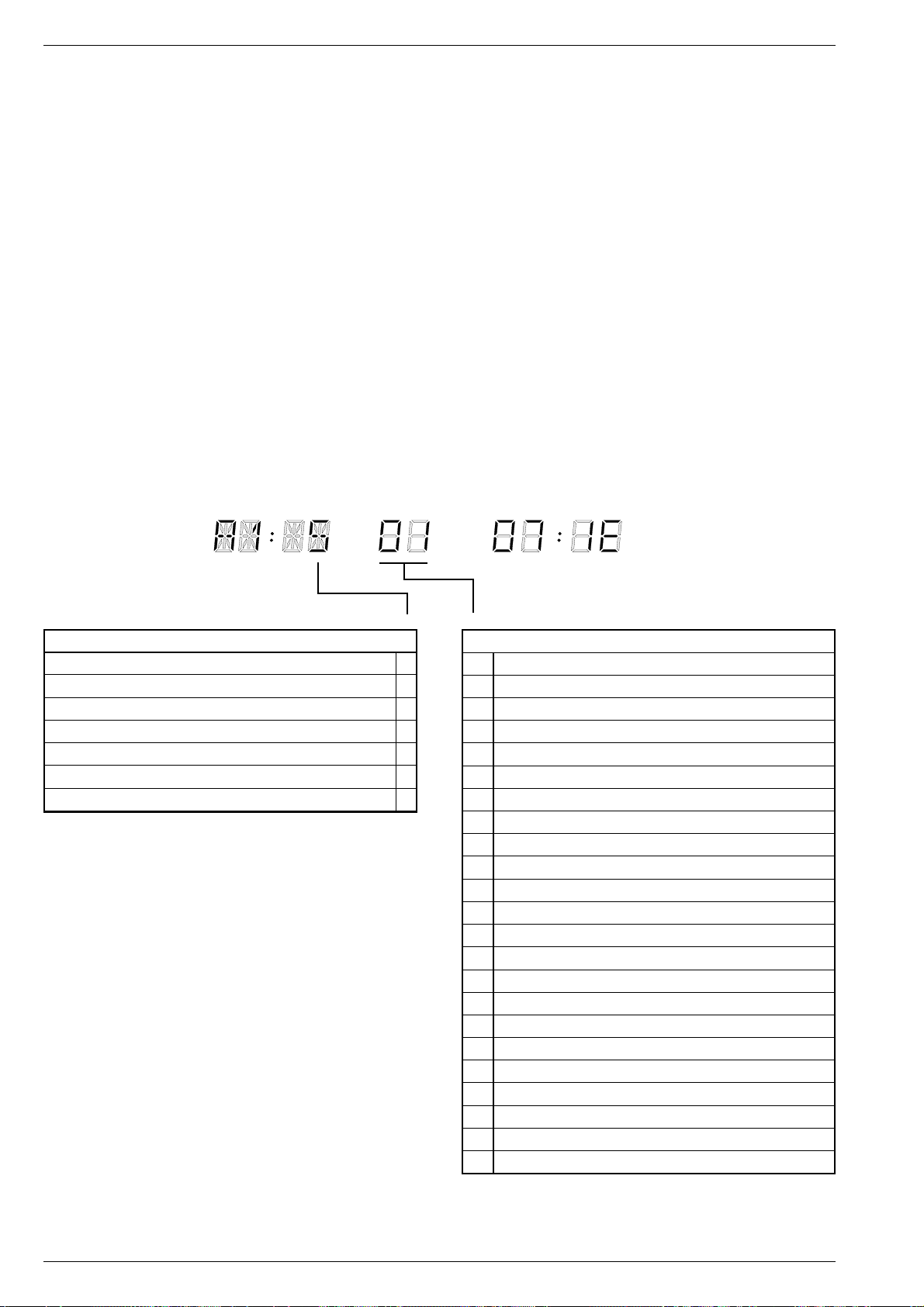
Servicetestprogramm / Service Test Programme
It`s Free
3. Überwachung der Laufwerksfunktionen
Wenn eines der nachfolgend beschriebenen Signale nicht vorliegt,
versucht das Gerät den Cassettenschacht in die Stellung "EJECT" zu
bringen.
3.1 Ein - und Ausfädeldauer
Als Referenz für die Ein - und Ausfädeldauer wird das Signal vom
Fädeltachogeber (FTA) genommen, der die Umdrehungen des Fädelmotors überwacht.
3.2 Stillstand des linken bzw. rechten Wickeltellers
Für diese Überwachung werden die Tachoimpulse vom linken (WTL)
und rechten (WTR) Wickelteller ausgewertet.
3.3 Stillstand des Kopfscheibenmotors
Zur Überwachung des Kopfscheibenmotors wird das PG/FG-Signal
verwendet. Dieses wird aus der EMK der nicht stromdurchflossenen
Spulen des Kopfscheibenmotors abgeleitet und gibt die Position der
Kopfscheibe an.
3.4 Capstanmotorfehler
Für diese Überwachung wird das Capstantacho-Signal (FG) verwendet.
3.5 Fehlercodes und Fehlerstatus
Der zuletzt aufgetretene Fehlercode wird im EEPROM abgespeichert
und bleibt auch dann erhalten, wenn das Gerät vom Netz getrennt wird.
Löschen kann man diesen Fehlercode durch Drücken der Taste
"CLEAR" auf dem Fernbediengeber im Servicemode.
Fehlercodes und Fehlerstatus für die 10-stellige Anzeige
3. Monitoring the Tape Deck Functions
If one of the signals described in the following is missing, the recorder
tries to move the cassette compartment to the "EJECT" position.
3.1 Threading-in and Threading-out Duration
The signal from the threading tacho generator (FTA) which monitors
the revolutions of the threading motor is taken as a reference for the
threading in and out duration.
3.2 No Rotation of the Left or the Right Reel
The signals sensed to check the rotation are the tacho pulses from the
left (WTL) and the right (WTR) reel.
3.3 No Rotation of the Headwheel Motor
The PG/FG signal is used for monitoring the headwheel motor. It is
derived from the e.m.f. of the non-current-carrying coil of the headwheel motor and indicates the position of the headwheel.
3.4 Error of the Capstan Motor
For monitoring the capstan motor the capstan tacho signal (FG) is
used.
3.5 Error Codes and Error Status
The last error code that occurred is stored in the EEPROM and is saved
even if the VCR is disconnected from the mains. To erase this error
code, press the "CLEAR" button on the remote control while in the
service mode.
Error Codes and Error Status for the 10-place Display
PROG
DATE
Laufwerk Fehlercode / Drive Mechanism Error Code
Kein Fehler / No error 0
Fädelfehler / Threading error 1
Kein Capstantacho / No capstan tacho 2
Band gerissen / Tape torn 3
fehlender Wickeltacho links / Missing left reel tacho 4
fehlender Wickeltacho rechts / Missing right reel tacho 5
Kopfscheibenmotorfehler / Headwheel motor error 6
START
STOP
Laufwerk Fehlerstatus / Drive Mechanism Error Status
00 Bereitschaft / Standby
01 Ausfädel - Fehler / Threading-out error
02 Stop
03 Standbild / Still
04 Wiedergabe / Play
05 Tuner
06 Aufnahme / Record
07 Wiedergabe +Tracking / Play + Tracking
08 Bildsuchlauf vorwärts / Picture search forward
09 Bildsuchlauf rückwärts / Picture search reverse
10 Vorlauf / Wind
11 Rücklauf / Rewind
12 Aufnahme - Pause / Record - Pause
13 Wiedergabe Rückwärts / Play reverse
14 Schneller Vorlauf / Fast forward
15 Schneller Rücklauf / Fast reverse
16 Zeitlupe (1/6) / Slow (1/6)
17 Zeitlupe (1/12) / Slow (1/12)
18 Zeitlupe (1/24) / Slow (1/24)
19 E-E-Betrieb / E-E-Mode
20 Bereitschaft-Schacht oben / Standby eject
21 Index next
22 Index previous
1 - 36 GRUNDIG Service-Technik
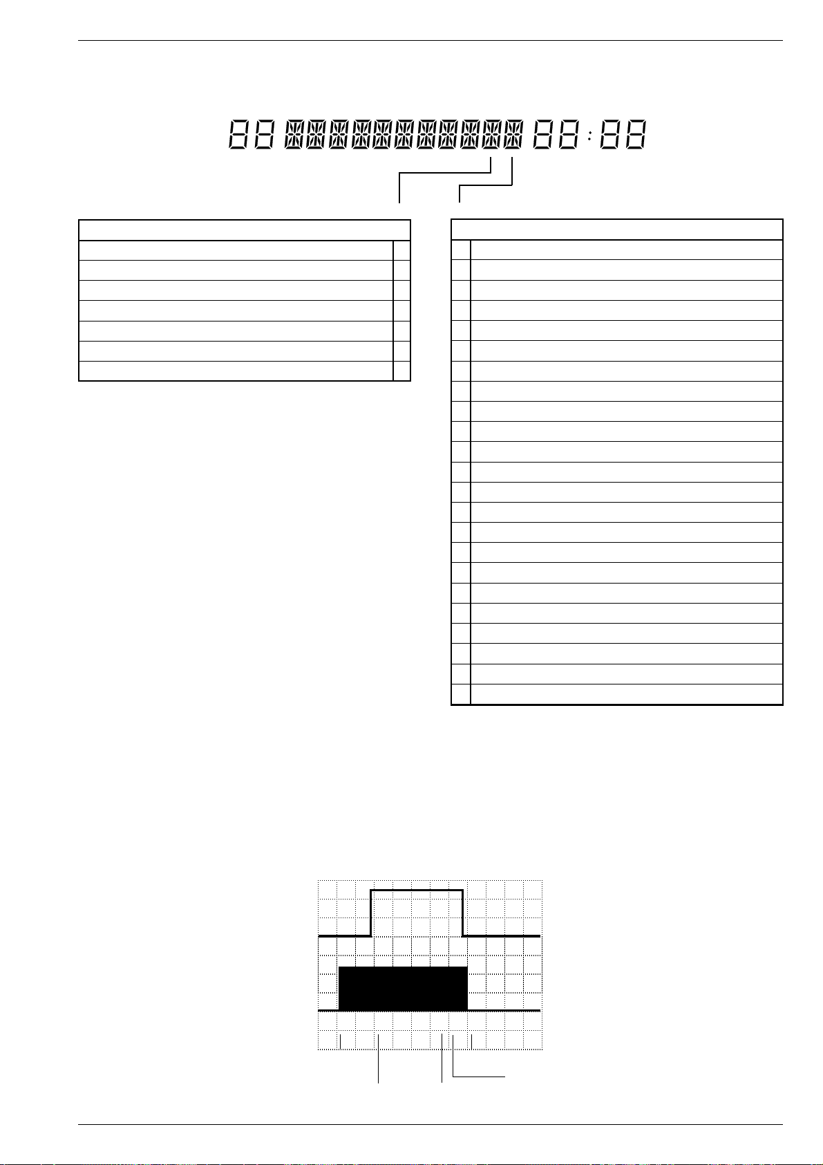
Servicetestprogramm / Service Test Programme
It`s Free
Fehlercodes und Fehlerstatus für die 17-stellige Anzeige Error Codes and Error Status for the 17-place Display
DECODER PDCVPS
Laufwerk Fehlercode / Drive Mechanism Error Code
Kein Fehler / No error 0
Fädelfehler / Threading error 1
Kein Capstantacho / No capstan tacho 2
Band gerissen / Tape torn 3
fehlender Wickeltacho links / Missing left reel tacho 4
fehlender Wickeltacho rechts / Missing right reel tacho 5
Kopfscheibenmotorfehler / Headwheel motor error 6
STARTLPTODAY
Laufwerk Fehlerstatus / Drive Mechanism Error Status
END
A Bereitschaft / Standby
B Ausfädelfehler / Unthreading error
C Stop
D Standbild / Still
E Wiedergabe / Play
F Tuner
G Aufnahme / Record
H Wiedergabe +Tracking / Play + Tracking
I Bildsuchlauf vorwärts / Picture search forward
J Bildsuchlauf rückwärts / Picture search reverse
K Vorlauf / Wind
L Rücklauf / Rewind
M Aufnahme - Pause / Record - Pause
N Wiedergabe Rückwärts / Play reverse
O Schneller Vorlauf / Fast forward
P Schneller Rücklauf / Fast reverse
Q Zeitlupe (1/16) / Slow (1/16)
R Zeitlupe (1/10) / Slow (1/10)
S Zeitlupe (1/6) / Slow (1/6)
T E-E-Betrieb / E-E-Mode
U Bereitschaft-Schacht oben / Standby eject
V Index next
W Index previous
4. Laufwerkstellung und Funktion des Init Schalters:
Das Diagramm zeigt die Funktion des Init-Schalters abhängig von der
Stellung des Laufwerks. Dafür ist die Anzahl der Fädeltacho - Impulse
(FTA) wichtig. Diese Impulse erzeugt der Fädeltachogeber (Flügelrad), der mechanisch mit dem Fädelmotor verbunden.
A: AC, 2V/Div, 0,5s/Div
B: AC, 2V/Div, 0,5s/Div
A
B
Cassette eingeschoben
Cassette in
Cassette unten
Cassette down
GRUNDIG Service-Technik 1 - 37
4. Tape Deck Position and Function of the Init Switch:
The diagram shows the function of the Init switch dependent on the
tape deck position. For this, the number of the threading tacho pulses
(FTA) is important. These signals are generated by the threading tacho
generator (butterfly sensor) which is mechanically connected with the
threading motor.
Init Schalter / Init switch
Fädeltacho-Impuls (FTA)
Threading pulse (FTA)
Wiedergabe / Play
Einfädeln / Thread in
Halber Ladezustand
Half loaded
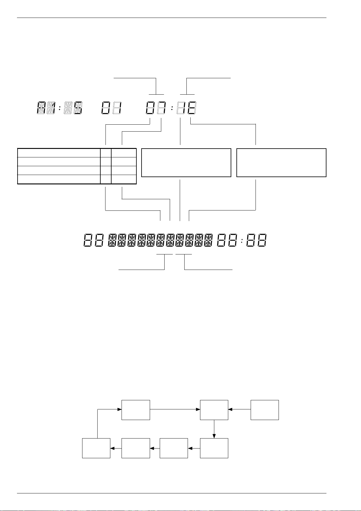
Servicetestprogramm / Service Test Programme
It`s Free
5. Kontrolle der Laufwerk Sensoren (Überprüfen ohne Cassette)
Die Anzeige zur Kontrolle der Laufwerksensoren erfolgt 4-stellig. In
einer Digitalstelle werden mehrere Sensoren angezeigt. Pro betätigtem Sensor ändert sich der Anzeigewert.
Mit den Laufwerkstellungen wird angezeigt, wo sich der Cassettenschacht und die Fädelschlitten befinden.
Laufwerksstellung
Tape drive state
PROG
DATE
Auswurf / Eject 0 5…9
Ausgefädelt-Stop / Stop threaded out 6 1…4
START
STOP
Wickeltacho links / Left reel tacho
Init Schalter / Init switch
Fädeltacho / Threading tacho (FTA)
Wiedergabeposition / Play position P 4…8
Wiedergabe rückwärts / Play reverse E D / E / F
5. Checking the Sensors (without a cassette loaded)
The indication of the deck sensor control is four-figured. Several
sensors are indicated in a digital place. The indicated value changes
with each operation of a sensor.
The tape drive indication shows the position of the cassette compartment and the threading roller units.
Laufwerkssensoren
Tape deck sensors
Bandende / End of tape (TAE)
Bandanfang / Beginning of tape (TAS)
Aufnahmesperre / Record protection
Wickeltacho rechts / Right reel tacho
DECODER PDCVPS
Laufwerksstellung
Tape drive state
6. Dauerlaufprüfung
Die Dauerlaufprüfung ist im Servicetestprogramm integriert. Diese hilft
Fehler zu finden, die sporadisch auftreten. Ein erkannter Fehler wird
im EEPROM gespeichert und bleibt erhalten, auch wenn das Gerät
vom Netz getrennt wird.
Aufruf der Dauerlaufprüfung
– Cassette einschieben.
– Servicetestprogramm starten durch gleichzeitiges Drücken der
Taste " STOP " auf der Fernbedienung und der Taste J am Gerät
für mindestens 5s.
– Dauerlaufprüfung starten mit den Tasten "REC", J oder F.
Anschließend durchläuft das Gerät die Dauerlaufprüfung entsprechend dem folgendem Schema.
Beenden der Dauerlaufprüfung
– Taste "STAND-BY" drücken oder Gerät vom Netz trennen.
STARTLPTODAY
END
Laufwerkssensoren
Tape deck sensors
6. Continuous Operation Test
The continuous operation test is part of the service test programme and
is used to find out occasionally occuring faults. The fault is stored in the
EEPROM and is saved even if the VCR is disconnected from the
mains.
Calling the Continuous Operation Test
– Insert a cassette.
– Enter the test programme by simultaneously pressing the "STOP"
button on the remote control and the J button on the video recorder
for at least 5 seconds.
– Start the continuous operation test by pressing the button "REC", J
or F. The video recorder is then subjected to the continuous
operation test as shown in the diagram below.
Terminating the Continuous Operation Test
– Press the "STAND-BY" button or disconnect the video recorder from
the mains.
Wiedergabe
Play
Einfädeln
Thread in
1 - 38 GRUNDIG Service-Technik
Bandanfang
Beginning of
tape
Rückspulen
Rewind
Bandende
End of Tape
Ausfädeln
Thread out
Aufnahme
Record

Beschreibungen / Descriptions
It`s Free
Beschreibungen
1. Netzteil (MSM1)
Das Netzteil ist für zwei IC-Konzepte ausgelegt: Bei einem ist der
Leistungstransistor im Ansteuer-IC integriert (SPH4690 - IC7105) und
beim anderen (TDA4605 - IC7110) ist dieser extern (T7135).
Diese Beschreibung ist beschränkt für die Variante mit dem externen
Leistungstransistor.
ln dem freischwingenden Sperrwandlernetzteil übernimmt der IC7110
die Ansteuerung und Überwachung des MOS-Leistungstransistors
T7135 sowie alle notwendigen Regelungs- und Überwachungsfunktionen. Über Pin 1 erhält IC7110 vom Optokoppler OK7210 (Netztrennung!) die Information über die Größe der sekundärseitigen 5,4VSpannung. Die Stromversorgung des IC7110 erfolgt an Pin 6 bis zum
Erreichen der Einschaltschwelle über die Widerstände R3112 und
R3119. Nach dem Anlauf wird die Versorgungsspannung über die
Diode D6115 aus der Wicklung 4, 3 des Wandlertrafos gewonnen.
Die Serienschaltung von Leistungstransistor T7135 und Primärwicklung 6…9 des Sperrwandlers liegt an der gleichgerichteten Netzspannung (C2112). Während der Leitphase des Transistors wird
Energie im Übertrager gespeichert und in der Sperrphase über die
Sekundärwicklungen abgegeben. Der IC7110 regelt über die Einschaltdauer des T7135 die übertragene Energie so nach, daß die
Sekundärspannungen weitgehend unabhängig von Netzspannung
und Last stabil bleiben. Die dazu nötige Regelinformation wird über
den Optokoppler gewonnen (s.o.). Außerdem erfolgt an IC7110-(8)
eine Nulldurchgangsdetektion aus der Wicklung 3, 4 über R3126.
Überspannungs- und Überlastschutz
Sollten im Störfall Überspannungen auftreten, spricht die Speisespannungsüberwachung im IC7110-(6) an und unterbricht die Ansteuerung
des MOS-Transistors T7135. Ist nach Wiederanlauf weiterhin Überspannung vorhanden, wiederholt sich der ganze Vorgang ("Abfragevorgang").
Bei einem Kurzschluß der Sekundärspannungen regelt der IC7110
mittels der Drainstromnachbildung (Pin 2) auf einen sich wiederholenden Abfragezustand und begrenzt somit die Leistung.
Netzunterspannung
Im IC7110 arbeitet über Pin 3 eine Schutzschaltung gegen Netzunterspannung. Den Ansprechwert bestimmen R3123 und R3121.
Descriptions
1. Power Supply (MSM1)
The power supply unit is designed for two IC-versions: One version has
the power transistor integrated in the driving IC (SPH4690 - IC7105),
the other version (TDA4605 - IC7110) has not; the transistor is an
external component (T7135) in this case.
The following description is confined to the version with the external
power transistor.
In this free-running blocking-oscillator type mains stage, the IC7110
carries out the drive and monitoring of the MOS power transistor T7135
and also all necessary control and monitoring functions. The IC7110
receives on pin 1 information from the optocoupler OK7210 (mains
isolation!) concerning the amplitude of the 5.4V supply on the secondary side. The current supply for the IC7110 takes place on pin 6 via
the resistors R3112 and R3119 until the switch-on level is reached.
After start up the supply voltage is obtained via the diode D6115 from
the winding 4, 3 of the transformer.
The series circuit consisting of the power transistor T7135 and the
primary winding 6…9 of the blocking oscillator transformer is connected to the rectified mains voltage (C2112). During the conducting
phase of the transistor, energy is stored in the transformer which is fed
to the secondary windings in the cut-off phase. The IC7110 controls the
transferred energy by the switch-on period of T7135 so that the
secondary voltages are held constant largely independent of mains
voltage and load variations. The required control information is produced via the optocoupler (see above). In addition, zero transition
detection is carried out on IC7110-(8) by the information from winding
3, 4 via R3126.
Overvoltage and Overload Protection
If an overvoltage condition occurs, the supply voltage monitoring circuit
responds via IC7110-(6) and interrupts the drive to the MOS transistor
T7135. If the overvoltage condition is still present after restart, the
complete process is repeated (“sensing process”).
With short circuit secondary voltages, the IC7110, in combination with
the drain current simulation (pin 2), takes up a repeated scanning state
and limits the power.
Mains Undervoltage
In IC7110 a protection circuit for mains undervoltage conditions
operates via pin 3. The threshold value is determined by R3123 and
R3121.
2. Chassisplatte (MFB)
2.1 Chassisplatte – Ablaufsteuerung /
Deckelektronik (DE)
Funktionsübersicht
Die Steuerung des Gerätes übernimmt der Ablaufrechner IC7410, IVC
(Intel Video Controller) und der Mikrocomputer IC7101 auf der Bedieneinheit. Der Datenaustausch zwischen den beiden Mikrocomputern
erfolgt über die bidirektionale serielle Schnittstelle DATD1 / CLKD1.
Der Ablaufrechner ist ein speziell für Videorecorder entwickelter
Mikrocomputer. Das Betriebssystem ist im integrierten maskenprogrammierten ROM und wird durch externe Beschaltung definiert:
Pin 23 LP-(4-Kopf) Die Festlegung erfolgt mit Bestük-
kung des Widerstandes R3463.
Pin 14 2-/3-Kopf-Umschaltung Die Festlegung erfolgt über den
eingesetzten Kopfverstärker.
Pin 26 Normumschaltung Bei LOW-Pegel über R3464 ist nur
die Anwahl von UHF-Sendern der
Norm PAL I (GB) möglich.
Die interne Rechnergeschwindigkeit beträgt 1MHz. Der Quarz Q1401
legt die Zeitreferenz fest.
Der Ablaufrechner übernimmt die Steuerung und die Kontrolle des
Laufwerks inklusive der Servosysteme für den Bandvorschub und der
Kopfradsteuerung. Des weiteren steuert dieser die Aufnahme-/
Wiedergabeumschaltung, sowie die Freigabe der Aufsprechströme.
Ein interner Schwarz/Weiß-Bildgenerator erleichtert den Modulatorabgleich.
2. Family Board (MFB)
2.1 Family Board – Sequence Control /
Deck Electronic (DE)
Function Overview
The video recorder is controlled by the sequence control computer
IC7410, IVC (Intel Video Controller), and the microcomputer IC7101
on the keyboard control unit. Data communication between the two
microcomputers is effected via the bidirectional serial interface DATD1/
CLKD1.
The sequence control computer is a microcomputer especially developed for video recorders. The operating system is stored in the
integrated mask-programmed ROM and is defined by externally connected circuits:
Pin 23 LP-(4-head) Defined by fitting the resistor
R3463.
Pin 14 2-/3-head switchover Defined by the head amplifier used.
Pin 26 Norm switchover With a LOW level present via
R3464 only UHF stations in PAL I
(GB) standard can be selected.
The internal computing speed is 1MHz. The quartz Q1401 determines
the time reference.
The sequence control computer is responsible for driving and checking
the drive mechanism and also the servo systems for the tape transport
and headwheel control. It controls the record/playback switching
process and the release of the recording currents.
An internal black/white video generator facilitates adjustment of the
modulator.
GRUNDIG Service-Technik 2 - 1

Beschreibungen / Descriptions
It`s Free
Die Ablaufsteuerung ist in folgende Funktionsgruppen unterteilt:
2.1.1 Reset
2.1.2 Steuerung des Fädelmotors (Cassettenschacht / Fädelmechanik)
2.1.3 Wickeltachoimpulsverarbeitung
2.1.4 Bandanfang-/ Bandende-Erkennung
2.1.5 Kopfservoregelung
2.1.6 Bandservoregelung
2.1.7 Trackingregelung / Autotracking
2.1.8 EEPROM
2.1.1 Reset
Den Einschaltreset, nach dem Anstecken des Gerätes ans Netz,
erzeugt IC7411 mit dem Resetkondensator C2414 an Pin 4. Der
daraus generierte "POR" (Power On Reset) an IC7411-(17) steht als
HIGH-Impuls (ca. 30ms) einmalig am Ablaufrechner IC7410-(15) an.
Des weiteren gelangt dieser Impuls über die phasendrehende Verzögerungsstufe T7030 / T7031 auf der Bedieneinheit als negierter
Impuls zum Bedienrechner IC7101-(12).
2.1.2 Steuerung des Fädelmotors (Cassettenschacht / Fädelmechanik)
Der Antrieb der Cassettenschacht - und Fädelmechanik erfolgt über
den Fädelmotor. Zur Ansteuerung des Fädelmotors gibt der Ablaufrechner IC7410 die Steuersignale TMO (Pin 27) und THIO (Pin 32)
aus. Mit diesen steuert man über den Fädelmotor-Treiber IC7402-(5),
-(6) / -(7), -(8) und Steckerkontakt F2-1, -3 den Fädelmotor.
Die Laufwerksposition erkennt der µC durch das Zählen der Fädeltachoimpulse (FTA) in Verbindung mit dem Schalter INIT sowie der
Kennung des "TAS" Bandanfangs sowie "TAE" Bandendes. Die
Fädeltachoimpulse (FTA) werden dem µC über Steckerkontakt F3-11
und IC7411-(5), -(15) zugeführt. Das Laufwerk enthält je einen Schalter zur Initialisierung des Fädeltachos (INIT) und zur Löschsicherung
(RECP). Die Spannungen entsprechend der Schaltzustände verkoppelt man über die Steckerkontakte 1502-14, -10, R3444 (INIT) sowie
R3445 (RECP) und führt diese dem IC7410-(57) zu.
Der Cassettenschacht ist mechanisch mit dem Fädeltachogeber (Flügelrad) verbunden. Beim Einschieben einer Cassette in den Cassettenschacht muß diese soweit eingeschoben werden, bis drei Fädeltachoimpulse erzeugt wurden. Danach aktiviert der Ablaufrechner den
Fädelmotor und übernimmt somit das Laden der Cassette.
Beim Auswurf (Eject) der Cassette werden kurz vor Erreichen der
Endposition des Cassettenschachtes die Empfänger für Bandanfangund Bandende-Kennung gleichzeitig freigegeben. Kurze Zeit später
schaltet der Ablaufrechner automatisch den Fädelmotor ab.
2.1.3 Wickeltachoimpulsverarbeitung
Die Optokoppler am linken und rechten Wickelteller (WTL / WTR)
geben pro Umdrehung des Wickels 8 Impulse ab. Diese werden im
IC7411 (Pins 7/6 –> Pins 13/14) in Rechteckimpulse umgeformt und
über die Pins 37 und 38 dem IC7410 zugeführt. Dieser errechnet aus
dem Verhältnis der beiden Frequenzen den augenblicklichen Bandstand und die Gesamtlänge der Cassette.
2.1.4 Bandanfang-/ Bandende-Erkennung
Zur Erkennung von Bandanfang und Bandende hat die VHS-Cassette
an den beiden Bandenden eine Klarsichtfolie von 13 bis 19cm Länge.
Über 2 Optokoppler wird Bandanfang und Bandende erkannt. Die über
T7404 getaktete Sendediode taucht dabei in der Cassettenmitte in ein
Loch ein. Die Empfänger sind links und rechts außerhalb der Cassette
angeordnet.
Die Phototransistoren "TAS" (Bandanfang) oder "TAE" (Bandende)
liefern Impulse, wenn sie Bandanfang oder -ende erkennen. Die
Ausgangsspannungen der Phototransistoren werden direkt den Analogeingängen des µCs IC7410-(58), -(55) zugeführt.
2.1.5 Kopfservoregelung
Die Kopfservoregelung sorgt für die richtige Drehzahl und Phase des
Kopfradantriebs. Die gesamte Regelung erfolgt dabei im µC (IC7410).
Die Istwerte werden im Kopfradmotor-Treiber (IC7301) im Kopfverstärker von den Informationen des Hallgenerators bzw. der Positionsspule im Kopfradmotor (Dreiphasenmotor) in Verbindung mit den
Phasenspannungen abgeleitet. Am Ausgang IC7301-(6) stehen sowohl die PG-Impulse (Phasengenerator) von 25Hz für die Phasenregelung als auch die FG-Impulse (Frequenzgenerator) von 450Hz für
die Drehzahlregelung. Über die Steckverbindung F4-1 gelangen die
FG-/PG-Impulse zum Ablaufrechner IC7410-(4).
The sequence control consists of the following function groups:
2.1.1 Reset
2.1.2 Threading motor control (cassette compartment / threading
mechanism)
2.1.3 Winding tachopulse processing
2.1.4 Beginning of tape / end of tape detection
2.1.5 Head servo control
2.1.6 Tape servo control
2.1.7 Tracking / autotracking
2.1.8 EEPROM
2.1.1 Reset
When connecting the video recorder to the mains, the IC7411 generates the switch-on reset pulse with the reset capacitor C2414 on Pin
4. The resulting "POR" (Power On Reset) on IC7411-(17) is applied
once as a HIGH pulse (approx. 30ms) to the sequence control
computer IC7410-(15). On another path, this pulse is also fed via the
phase-shifting delay circuit T7030 / T7031 on the keyboard control
board to the control computer IC7101-(12) as a negated pulse.
2.1.2 Threading Motor Control (cassette compartment / threading mechanism)
The cassette compartment and threading mechanism is driven by the
threading motor. For driving the threading motor, the sequence control
computer IC7410 feeds out the control signals TMO (Pin 27) and THIO
(Pin 32). This signal drives the threading motor via the threading motor
driver IC7402-(5), -(6) / -(7), -(8) and plug contact F2-1, -3.
The µC detects the position of the tape deck by counting the threading
tachopulses (FTA) in connection with the INIT switch and the identification "TAS" for the beginning of the tape, and "TAE" for the end of the
tape. The threading tachopulses (FTA) are supplied to the µC via plug
contact F3-11 and IC7411-(5), -(15). The tape deck is fitted with a
switch for initialisation of the threading tacho (INIT) and another for
erase protection (RECP). The voltages resulting from the switch
settings are coupled via the plug contacts 1502-14, -19, R3444 (INIT)
and R3445 (RECP) and fed to the IC7410-(57).
The cassette compartment is mechanically connected with the threading tacho generator (vane wheel). When loading a cassette into the
cassette compartment the cassette must be inserted as far as is
necessary to generate three threading tachopulses. Afterwards, the
sequence control computer activates the threading motor which then
takes over the loading of the cassette.
When ejecting the cassette, the phototransistors detecting the beginning and the end of the tape are enabled simultaneously a short time
before the lift reaches the end position. A short time later, the threading
motor is automatically switched off by the sequence control computer.
2.1.3 Winding Tachopulse Processing
The optocouplers on the left (WTL) and right (WTR) reels produce 8
pulses per revolution. These pulses are formed into rectangular
signals by IC7411 (pins 7/6 –> pins 13/14) and applied to pins 37 and
38 of IC7410. This IC calculates the instantaneous tape position and
the total length of the cassette from the ratio of these two frequencies.
2.1.4 Beginning of Tape / End of Tape Detection
To identify the beginning of tape and end of tape, the VHS cassette has
a clear foil, 13 -19cm long, on each end of the tape. The beginning and
end of tape is identified by two optocouplers. For this purpose, the
transmitting diode which is triggered by T7404 is inserted into a hole
in the middle of the cassette. The phototransistors are located at the
outside, left and right, of the cassette.
The phototransistors "TAS" (beginning of tape) or "TAE" (end of tape)
supply pulses as soon as they detect the beginning or end of tape. The
output voltages of the phototransistors are directly taken to the analog
inputs of the µC IC7410-(58), -(55).
2.1.5 Head Servo Control
The head servo control ensures that the rotational speed and the
phase of the headwheel drive are correct. The complete control is
carried out in the µC (IC7410). The actual values are derived in the
headwheel motor driver (IC7301) in the head amplifier from the
information given by the Hall generator or the position coil located in the
headwheel motor (threephase motor) in connection with the phase
voltages. At the output IC7301-(15) there are the PG (phase generator)
pulses of 25Hz for the phase control and also the FG (frequency
generator) pulses of 450Hz for the speed control. From the connector
F4-1 the FG/PG pulses are fed to the sequence control computer
IC7410-(4).
2 - 2 GRUNDIG Service-Technik

Beschreibungen / Descriptions
It`s Free
An IC7410-(31) gibt der µC ein impulsbreitenmoduliertes Rechtecksignal (REEL) aus, das sowohl Drehzahl- als auch Phaseninformationen
enthält. Dieses wird über Steckerkontakt F4-6 dem Kopfradmotortreiber IC7301 im Kopfverstärker als Regelspannung zugeführt.
2.1.6 Bandservoregelung
Der Capstanmotor ist ein Dreiphasenmotor, der mit Hallgeneratoren
bestückt ist. Diese erzeugen Signale, die dem Capstanmotor-TreiberIC (CXA-8005AS) auf der Capstanmotor-Einheit über die Pins 1…6
zugeführt werden. Abhängig von diesen Signalen erfolgt in diesem die
Kommutierung der einzelnen Phasen des Capstanmotors.
Die Drehrichtungsumschaltung (CREV) erfolgt über den Pin 15 des
CXA-8005AS. Dazu gibt der µC (IC7410) an Pin 19 für die Drehrichtung vorwärts LOW-Pegel bzw. rückwärts HIGH-Pegel aus. Dieses Steuersignal wird über D6402 und den Steckerkontakt F3-4 dem
Capstanmotor-Treiber zugeführt. Für die Drehzahlregelung gibt das
FG-Hallelement (Magneto Recitive Element) des Capstanmotors Impulse mit einer Frequenz von 1514Hz bei Nenndrehzahl ab. Diese
werden im Capstanmotor-Treiber verstärkt, über Steckerkontakt F3-2
und Pin 8 des IC7411 dem internen Komparator zugeführt. Die
Tachoimpulse (Istwert) werden im IC7410 mit einem intern erzeugten
Sollwert verglichen. Über IC7410-(30) gibt der µC eine impulsbreitenmodulierte Rechteckspannung (CAP) aus. Diese wird mit R3448 /
C2419 integriert und über Steckerkontakt F3-3 als Regelspannung
dem Capstanmotor-Treiber-IC (CXA-8005AS) zugeführt.
Bei den Funktionen "Spulen" und "Bildsuchlauf" (≥3) wird die
Versorgungsspannung des Capstanmotor-Treibers von +8,8V (+8M2)
auf +14,6V(+14M1) umgeschaltet. Dies erfolgt über das Steuersignal
(WIND) vom Ablaufrechner IC7410-(9) und die Transistorstufe
T7406…T7408.
2.1.7 Trackingregelung / Autotracking
Während der Aufnahme werden über den Synchronkopf codierte
25Hz-CTL-Impulse auf das Band aufgezeichnet, die bei Wiedergabe
zur Spurnachführung und für den Indexsuchlauf benötigt werden.
Diese 25Hz-Impulse gelangen bei Aufnahme von IC7410-(6) zum
IC7411-(16) und von hier über IC7411-(2) und die Steckverbindung
F8-1 / -2 an den Synchronkopf.
Bei Wiedergabe werden die aufgesprochenen CTL-Impulse vom
Synchronkopf abgetastet, im IC7411 in Rechteckimpulse umgeformt
und über IC7411-(16) dem IC7410-(6) zugeführt.
Nach dem Einlegen einer Cassette wird bei Wiedergabe mit Hilfe der
Autotracking-Funktion die optimale Spurlage ermittelt. Zu diesem
Zweck führt man dem Hauptrechner IC7410 über den Analogeingang
(Pin 54) eine von der Hüllkurve der FM-Pakete abgeleitete Spannung
"TRIV" (Trackinginformation Video) zu. Diese wird im Kopfverstärker
erzeugt.
Ausgehend von der Tracking-Mittellage wird der Tracking-Sollwert
vergrößert und verkleinert. Für jede der beiden Richtungen wird nun
der zugehörige Sollwert ermittelt, bei dem die von der FM-Hüllkurve
"TRIV" abgeleitete Spannung gegenüber dem maximal ermittelten
Spannungswert abzunehmen beginnt. Als optimaler Trackingwert
wird der Mittelwert zwischen den beiden Eckwerten eingestellt. Nach
Abschluß dieser Messung wird die Autotracking-Funktion abgeschaltet und die ermittelte Phasenlage über die CTL-Impulse geregelt.
Fehlen mehr als zwei aufeinanderfolgende CTL-Impulse, wird das
Autotracking erneut gestartet. Es wird in diesem Fall davon ausgegangen, daß eine neue Aufnahme mit anderer Trackinglage vorliegt.
Beim Abbruch des Autotracking, mit der Taste " 2", wird der aktuelle
Tracking-Wert vom µC festgesetzt. Die Phasenregelung hat die Aufgabe, die eingestellte Tracking-Soll-Lage festzuhalten.
2.1.8 EEPROM
Im 8kBit-EEPROM (IC7412) speichert der Bedienrechner (IC7101)
kunden- und gerätespezifische Daten (z.B. Sendereinstellungen-Kanäle, Software-Abgleichwerte). Die Datenübertragung erfolgt über
den I2C-Bus (SDA / SCL).
On IC7410-(31) the µC feeds out a pulse-width-modulated squarewave signal (REEL) containing information on the speed and the
phase. This signal is fed via the plug contact F4-6 to the headwheel
motor driver IC7301 located in the head amplifier and is used as a
control voltage.
2.1.6 Tape Servo Control
The capstan motor is a three-phase motor which is fitted with Hall
generators. These generate signals which are fed to the capstan motor
driver IC (CXA-8005AS) on the capstan motor assembly via the pins
1…6. Depending upon these signals the IC commutates the individual
phases of the capstan motor.
Switching over of the sense of rotation (CREV) is carried out via pin 15
of the CXA-8005AS. For this the µC (IC7410) feeds out from pin 19 a
LOW level for the forward sense of rotation or a HIGH level for the
reverse direction. This control signal is passed through D6402 and
plug contact F3-4 to the capstan motor driver. For speed control, the
FG Hall element (Magneto Recitive Element) in the capstan motor
generates pulses at a frequency of 1514Hz at the rated speed. The
pulses are amplified in the capstan motor driver and fed to the internal
comparator via plug contact F3-2 and pin 8 of the IC7411. The
tachopulses (actual value) are compared in the IC7410 with an
internally generated reference value. From IC7410-(30) the µC feeds
out a pulse-width-modulated square wave voltage (CAP). This is
integrated by R3448 / C2419 and fed via plug contact F3-3 as a control
voltage to the capstan motor driver IC (CXA-8005AS).
For the functions "Wind/Rewind" and "Picture Search Forward/Backward" (≥3) the supply for the capstan motor driver is switched over from
+8.8V (+8M2) to +14.6V (+14M1). This is done by the control signal
(WIND) from the sequence control computer IC7410-(9) and the
transistor stage T7406…T7408.
2.1.7 Tracking / Autotracking
During recording, encoded 25Hz-CTL-pulses are recorded onto the
tape via the sync head. These pulses are required on playback for
tracking control and for index search.
On recording, the 25Hz pulses are taken from IC7410-(6) to IC7411-(16)
and are then passed through IC7411-(2) and the connector F8-1 / -2
to the sync head.
On playback, the recorded CTL pulses are scanned by the sync head
to be subsequently converted to square wave pulses in IC7411 and
passed on via IC7411-(16) to IC7410-(6).
When a cassette is loaded, the Autotracking function determines the
optimum track position on playing back. For this, a voltage "TRIV"
(TRacking Information Video) is derived from the envelope of the FM
packages and fed in to the main computer IC7410 on the analog input
(pin 54). This voltage is generated in the head amplifier.
On the basis of the tracking centre position, the nominal tracking value
is increased or reduced. For each of the two directions, an appropriate
nominal value is determined at which the voltage derived from the FM
envelope "TRIV" starts to decrease as against the maximum determined voltage level. The mid-value between the two limit values is then
used as the optimum tracking value. On completion of this measurement, the autotracking function is switched off and the determined
phase is controlled by the CTL pulses.
If more than two successive CTL pulses are missing, the autotracking
function is reactivated assuming, in this case, that a new recording with
a different tracking position is played back.
When stopping the autotracking function with the "2" button the
nominal tracking value is fixed by the µC. The phase control has the
task of maintaining the nominal tracking position once it has been set.
2.1.8 EEPROM
In the 8kBit-EEPROM (IC7412) the control computer (IC7101) stores
special data of the customer and the machine (eg. station tuning data/
channels, software/adjustment values). The data is transferred via the
I2C-bus (SDA / SCL).
GRUNDIG Service-Technik 2 - 3

Beschreibungen / Descriptions
It`s Free
2.2 Chassisplatte – Empfangseinheit (FV)
Signalverarbeitung
Die Empfangseinheit hat die Aufgabe, das vom Tuner kommende ZFSignal zu verstärken und zu demodulieren. Es entstehen dabei das
FBAS-Signal und das Audio-Signal.
Vom Kontakt 17 des Tuners kommend durchläuft das ZF-Signal das
Oberflächenwellenfilter F1721, das die ZF-Durchlaßkurve bestimmt.
Über IC7702-(1), -(2) führt man es einem regelbaren Breitbandverstärker mit Synchrondemodulator und danach einem Videoverstärker zu. Des weiteren erzeugt man in diesem IC die Regelspannung für den Breitbandverstärker und den Tuner. Diese Regelspannung
gelangt über IC7702-(12) und den Transistor T7712 zum Tuner
(Kontakt 5). Ihr Regeleinsatz ist mit R3724 (AGC) einstellbar. Das
demodulierte ZF-Signal durchläuft zwischen Pin 13 und Pin 14 des
IC7702 einen Ton-Trap F1722, wo man den Tonanteil im FBAS-Signal
absenkt. Anschließend wird es verstärkt und über IC7702-(7) sowie
der Verstärkerstufe T7705 dem "IN/OUT / Video/Chroma"-Schaltungsteil zugeführt.
Das demodulierte ZF-Signal für die Tonverarbeitung wird über
IC7702-(13) ausgekoppelt. Über das ZF-Filter F1723 bzw. F1724 und
IC7702-(11) führt man es der FM-Demodulation zu. An IC7702-(9)
steht das NF-Signal, das über den "IN/OUT / Video/Chroma"-Schaltungsteil zum Ton-Schaltungsteil weitergeleitet wird. Das Deemphasisglied R3305/ C2500 ist im "IN/OUT / Video/Chroma"-Schaltungsteil.
Tunerabstimmspannung und Bandwahl
Der Bedienrechner IC7101 auf der Bedieneinheit gibt in digitaler Form
die Höhe der Abstimmspannung vor. Das pulsbreitenmodulierte Signal (PWM) des 8-Bit-Rechners ermöglicht 256 verschiedene Möglichkeiten. Für die genaue Abstimmung ist diese Rasterung jedoch
nicht ausreichend. Die serielle Schnittstelle (SDA / SCL / STROBE)
mit 8 Bit gibt die Feinabstimmung mit weiteren 6 Bit vor. Die verbleibenden 2 Bit werden für die Bandwahl benötigt.
Von der Bedieneinheit gelangen die digitalen Abstimmwerte (TTLPegel) zum MOS-Pegelwandler IC7704 (Pin 11 - PWM, Pin 4 - SDA /
Pin 12 - SCL / Pin 5 - STROBE). Mit diesem setzt man die Signale von
5V (TTL-Pegel) auf 12V um. An den Pegelwandlerausgängen des
IC7704 (Pin 10 - PWM, Pin 2 - SDA / Pin 3 - SCL / Pin 6 - STROBE)
stehen die digitalen Abstimmwerte zur weiteren Verarbeitung an.
Das umgesetzte pulsbreitenmodulierte Signal PWM für die GrobAbstimmung wird von IC7704-(10) zum Integrator IC7700-(2), -(3)
weitergeleitet. Dieser setzt das PWM-Signal in eine Gleichspannung
(0...12V / 256 Stufen) um. In der folgenden Addierstufe (R3707 /
R3708 / R3701) wird es mit der Spannung zur Feinabstimmung
addiert.
Mit den umgesetzten Daten zur Feinabstimmung von der seriellen
Schnittstelle (SDA / SCL / STROBE) lädet man das 8-Bit Schieberegister (IC7701) mit integriertem Speicher. Dieses wird mit den seriellen
Daten SDA an Pin 2 und der zugehörigen Taktfrequenz SCL an Pin 13
geladen. Der anschließend übertragene Befehl STROBE an Pin 1
übernimmt die parallelen Daten des Schieberegisters in den Speicher.
An den Pins 4...7, 11 und 12 gibt dieses die Daten für die Tuner-Feinabstimmung aus. Anschließend bildet man über den passiven D/AWandler, R1701 (R-2R-Netzwerk) eine Spannung (0...12V / 64 Stufen). Diese steht am Pin 8 des Widerstandsnetzwerkes und wird über
R3708 zur groben Abstimmspannung addiert. Das Summenprodukt
mit 14-Bit-Auflösung ist auf 12V begrenzt. Die generierte Tunerabstimmspannung wird mit dem Pegelwandler, IC7700 (Pin 5...7) und T7713,
T7714, auf einen Regelbereich von 0...33V umgesetzt und dem Tuner
über Kontakt 11 zugeführt.
Von den verbleibenden 2 Bit des seriellen 8-Bit-Datenwortes, das in
das Schieberegister eingelesen wurde, generiert man die Schaltspannungen zur Bandwahl. An den Ausgangspins 13 und 14 des
IC7701 stehen die 2 Bit zur Verfügung und schalten über die Transistoren T7708, T7709, T7710 und T7711 das vorgewählte Band ein.
Band 1 Pin 13 = LOW, Pin 14 = LOW
Band 3 Pin 13 = LOW, Pin 14 = HIGH
UHF Pin 13 = HIGH, Pin 14 = LOW
2.2 Family Board – Frontend (FV)
Signal Processing
The Frontend has the function of amplifying and demodulating the IF
signal fed in from the tuner. The resulting signals are the CCVS signal
and the audio signal.
From the tuner contact 17, the IF signal passes through the surface
acoustic wave filter F1721, which determines the IF band pass. Via
IC7702-(1), -(2), the signal is fed to a gain controlled wideband
amplifier with synchronous demodulator, and subsequently, to a video
amplifier. Another stage in the IC is used to generate the control
voltage for the wideband amplifier and the tuner. This control voltage
is fed from IC7702-(12) and the transistor T7712 to the tuner (contact
5). The control threshold level is adjustable with R3724 (AGC).
Between pin 13 and pin 14 of the IC7702, the demodulated IF signal
passes through a sound trap F1722, in which the audio component of
the CCVS signal is attenuated. Subsequently, the signal is amplified
and passed on to the "IN/OUT / Video/Chroma" circuit stage via
IC7702-(7) and the amplifier T7705.
The demodulated IF signal for sound processing is fed out from
IC7702-(13). Via the IF filter F1723 or F1724 and IC7702-(11), the
signal is fed in for FM demodulation. On IC7702-(9) the AF signal is
present which is passed on via the "IN/OUT / Video/Chroma" circuit
stage to the Sound stage. The de-emphasis network R3305/C2500 is
located in the "IN/OUT / Video/Chroma" circuit stage.
Tuning Voltage and Band Selection
The control computer IC7101 on the keyboard control module generates and digitises the tuning voltage level. The pulse-width-modulated
signal (PWM) from the 8-Bit computer offers 256 different possibilities.
However, for exact tuning this resolution is not sufficient. The serial
interface (SDA / SCL / STROBE) of 8 bits determines the fine tuning
value by means of additional 6 bits. The remaining two bits are used
for band selection.
From the keyboard control unit the digital tuning values (TTL level) are
supplied to the MOS level transformer IC7704 (Pin 11 - PWM, Pin 4 SDA / Pin 12 - SCL / Pin 5 - STROBE) which converts the signals from
5V (TTL level) to 12V. The digital tuning values are present at the level
transformer outputs of the IC7704 (Pin 10 - PWM, Pin 2 - SDA / Pin 3
- SCL / Pin 6 - STROBE) for further processing.
The converted pulse-width-modulated signal PWM for coarse tuning is
passed on from IC7704-(10) to the integrator IC7700-(2), -(3). This IC
transforms the PWM signal to a direct voltage (0...12V / 256 steps). In
the adding stage which follows (R3707 / R3708 / R3701) this voltage
is added to the fine tuning voltage.
The converted data for fine tuning from the serial interface (SDA /
SCL / STROBE) are loaded into the 8-bit shift register (IC7701) with
integrated memory. This register is loaded with the data SDA at Pin 2
and the respective clock frequency SCL at Pin 13. The following
STROBE command fed out from Pin 1 loads the parallel data from the
shift register into the memory. From the Pins 4...7, 11 and 12 the shift
register supplies the data for fine tuning of the tuner. Subsequently, a
voltage (0...12V / 64 steps) is generated via the passive D/A converter
R1701 (R-2R network). This voltage is applied to Pin 8 of the resistor
network and is added to the coarse tuning voltage via R3708. The sum
signal with 14-bit-resolution is limited to12V. The generated tuner
control voltage is converted to a control range of 0...33V with the level
transformer IC7700 (Pin 5...7) and T7713, T7714 and supplied to the
tuner via contact 11.
From the remaining 2 bits of the serial 8-bit data word read into the shift
register the band switching voltages are produced. The 2 bits are
available from the output pins 13 and 14 of the IC7701 for switching
over to the preselected band via the transistors T7708, T7709, T7710
and T7711.
Band 1 Pin 13 = LOW, Pin 14 = LOW
Band 3 Pin 13 = LOW, Pin 14 = HIGH
UHF Pin 13 = HIGH, Pin 14 = LOW
2 - 4 GRUNDIG Service-Technik
 Loading...