

Grundig MS-502 Service Manual

Service-Management
Service Manual
MS 502 (G.HK 59-00)
Inhaltsverzeichnis
D
Seite
Allgemeiner Teil .............................................. 2
Bedienhinweise .............................................................................. 2
Abgleichvorschriften .............................. 4 … 9
Schaltpläne und
Druckplattenabbildungen................... 10 … 40
Schaltpläne
HF-Teil ...................................................................................... 10
Klangsteller ............................................................................... 14
Prozessor-Teil........................................................................... 17
Cassetten-Teil........................................................................... 21
NF-Teil ...................................................................................... 23
Bedienplatten ............................................................................ 26
Anschlußplatte .......................................................................... 30
Druckplattenabbildungen .............................................................. 32
Ersatzteillisten und
Explosionszeichnungen ..................... 41 … 44
Ersatzteilliste und Explosionszeichnung Laufwerk ...................... 41
Ersatzteilliste MS 502 .................................................................. 43
Table of Contents
GB
Page
General Section............................................... 3
Operating Hints .............................................................................. 3
Adjustment Procedures.......................... 6 … 9
Circuit Diagrams
and Layout of PCBs ............................ 10 … 40
Circuit Diagrams
RF Part ..................................................................................... 10
Sound Control ........................................................................... 14
Processor Part .......................................................................... 17
Cassette Part ............................................................................ 21
AF Part...................................................................................... 23
Operating Boards...................................................................... 26
Connecting Board ..................................................................... 30
Layout of PCBs ............................................................................ 32
Spare Parts Lists and
Exploded Views................................... 41 … 44
Spare Parts List and Exploded View Tape Drive ......................... 41
Spare Parts List MS 502 .............................................................. 43
Zusätzlich erforderliche Unterlagen für den Komplettservice
Additionally required Documents for the Complete Service
Service
Manual
Sicherheit
Safety
Materialnr./Part No.
72010 800 0000
Dieses Service Manual ist nur in Datenform verfügbar
This Service Manual is only available as data
Änderungen vorbehalten
Subject to alteration
Made by GRUNDIG in Germany
E-BS 36 1199
http://www.grundig.com
Allgemeiner Teil / General Section
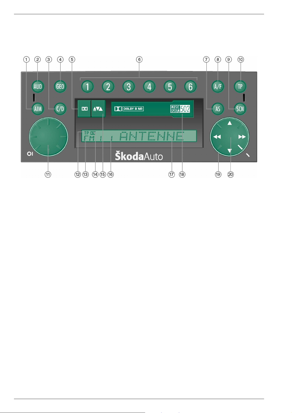
Bedienhinweise
MS 502
Bedientasten
1 AIM-Taste
Die AIM-Funktion dient zum Speichern und Wiedergeben von
Verkehrsmeldungen. Die Wiedergabe starten Sie durch Drücken
der AIM-T aste.
– Bei eingeschaltetem Radio wird jede Verkehrsmeldung aufgezeichnet.
2 Klangeinstellungstaste
durch Drücken der Klangeinstellungstaste und Drehen des Dreh-/
Drückknopfes §? Einstellung vornehmen.
– 1 x Drücken Tiefeneinstellung (BASS)
– 2 x Drücken Höheneinstellung (TRE)
3 Quellenwahltasten
durch Antippen wechseln Sie die Programmquelle bei eingeschobener Cassette bzw. angeschlossenem CD-Changer.
4 Geometrietasten
durch Drücken der Geometrietaste, und Drehen des Dreh-/
Drückknopfes §? Einstellung vornehmen.
– 1 x Balance (BAL)
– 2 x Fader (FAD)
5 Dolby®-Taste
zum Ein- bzw. Ausschalten der Dolby®-Rauschunterdrückung.
6 Stationstasten
für 12 FM-, und 12 AM-Sender.
– im CD-Wechslerbetrieb dienen die Stationstasten zur Auswahl
der CDs 1 – 6.
7 AS-Taste
mit der AS-Taste können Sie 6 Sender je Bereich automatisch speichern lassen.
8 A/F-Taste
mit der A/F-Taste können Sie zwischen FM 1/2 und AM 1/2 bzw.
von CC- oder CD-Betrieb auf Rundfunk umschalten.
9 SCN-Taste
durch Drücken können Sie im Radio-, Cassetten- oder CD-Betrieb
Sender bzw. Titel kurz anspielen lassen.
§I TP/Set-Taste
durch Antippen schalten Sie die Verkehrs-Funktionen ein.
Durch längeres Drücken gelangen Sie in das Setup-Menü.
§? Dreh-/Drückknopf
– Ein-/Ausschalten: Knopf drücken
– Lautstärkeregler: Knopf drehen
– Klangeinstellung: Klangeinstellungstaste 2 drücken, Knopf drehen
– Geometrieeinstellung: Geometrieeinstellungstaste 4 drücken,
Knopf drehen.
§E Autoreverse / Cassettenausschub
antippen: Autoreverse
länger drücken: Cassettenausschub.
§Z Cassettenschacht
§U Blinkdiode
Bei ausgeschaltetem Gerät und abgezogenem Zündschlüssel und
abgenommenem Bedienteil zeigt diese Diode durch ihr Blinken,
dass es sich um ein Autoradio mit Anti-Diebstahl-Codierung handelt.
«I Suchlauf-Wippe und abnehmbares Bedienteil
durch Antippen können Sie im AM-Bereich einen Sender-Suchlauf
starten.
Im FM-Bereich können Sie in der Speicherliste blättern.
Anzeigen
§` TP-Anzeige
§Q Wellenbereichsanzeige
§W Dolby®
§R Stationstastenanzeige
§T Sendername
Dolby Rauschunterdrückung ist hergestellt unter Lizenz von Dolby
Laboratories Licensing Corporation.
DOLBY und das Doppel-D-Symbol g sind Warenzeichen der Dolby
Laboratories Licensing Corporation.
2 GRUNDIG Service
MS 502
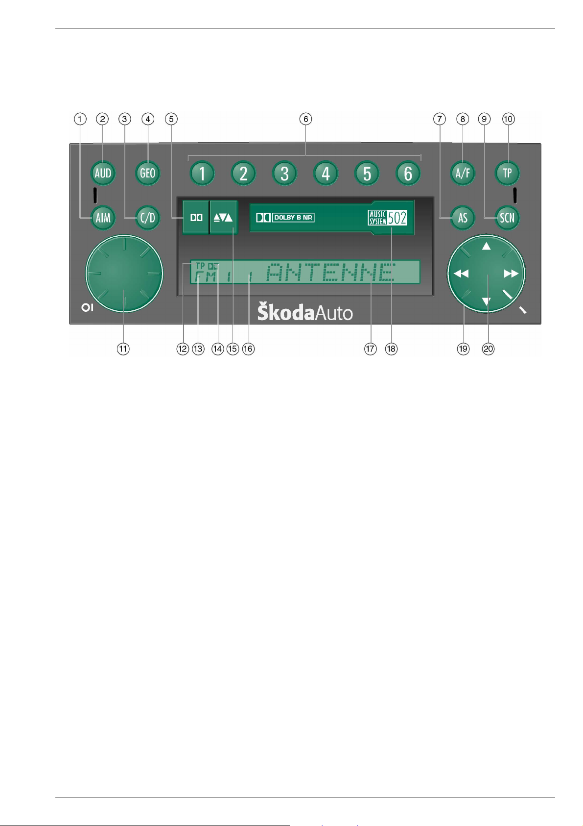
Operating Hints
Allgemeiner Teil / General Section
Buttons
1 AIM button
The AIM function serves for storing and playing back traffic announcements. Playback is started by pressing the AIM button.
– With the radio switched on, every traffic announcement is recorded.
2 Tone control
Press the tone control buttons and turn the control knob/push
button §? to change the setting.
– 1 pressure: bass control (BASS)
– 2 pressures: treble control (TRE)
3 Source selection button
Briefly press the button to change the programme source with a
cassette inserted or a CD changer connected.
4 Tone balance button
Press the tone balance button and turn the control knob/push
button §? to change the setting
– 1 pressure: balance (BAL)
– 2 pressures: fader (FAD)
5 Dolby® button
Serves for switching on and off the Dolby® noise reduction system.
6 Station buttons
for 12 FM and 12 AM stations.
– When in CD changer mode, the station buttons serve for selecting
the CD’s 1 to 6.
7 AS button
This button serves for the automatic storage of 6 stations in every
range.
8 A/F button
This button serves for switching over between FM 1/2 and AM 1/2
or between CC or CD mode and radio mode.
9 SCN button
Pressing this button briefly plays stations in radio mode or tracks in
cassette or CD mode.
§I TP/Set button
Briefly pressing this button switches on the traffic programme
functions.
Pressing this button a longer time displays the Setup menu.
§? Control knob/push button
– Switch on/off: press the button.
– Volume control: turn the knob.
– Tone control: press the tone control button 2 then turn the control
knob.
– Tone balance: press the tone balance button 4 then turn the
control knob.
§E Autoreverse / Cassette ejection
Brief pressure: autoreverse.
Long pressure: cassette ejection.
§Z Cassette compartment
§U Security diode
When the radio is switched off and the ignition key and the control
unit are removed, this diode will flash to signal that the car radio is
theft-protected by a code system.
«I Station search rocker
Briefly press the rocker to start a station search cycle in the AM
range.
When in the FM range, you can scroll through the memory list.
Display
§` TP indication
§Q Wavebands
§W Dolby®
§R Station buttons indication
§T Station name
Dolby noise reduction is manufactured under license from Dolby
Laboratories Licensing Corporation. DOLBY and the Double D symbol
g are registered trademards of the Dolby Laboratories Licensing
Corporation.
GRUNDIG Service
3
Abgleichvorschriften / Adjustment Procedures
D
Abgleichvorschriften
MS 502
1. Hauptplatte
Meßgeräte: DC-Voltmeter, Meßsender, NF-Voltmeter, Stereo-Coder, Wobbler, Oszilloskop
Aufruf des ´extended Expert Modus´:
Gerät ausschalten. Stationstaste 2 drücken, gedrückt halten und Gerät einschalten. Stationstaste 2 länger als 10 Sekunden gedrückt halten. GEOTaste drücken und ca. 4 Sekunden gedrückt halten, bis im Display SKODA - XX erscheint (XX = Versionsnummer). Taste TP drücken und 2 Sekunden
gedrückt halten. Nach dem Loslassen muss im Display PAR erscheinen. Mit den Tasten 5 bzw. 6 der Suchlaufwippe den entsprechenden
Parametersatz anwählen (Anzeige z.B. PAR 05). Taste TP kurz drücken (Anzeige ändert sich von PAR in CH). Mit den Tasten 5 bzw. 6 der
Suchlaufwippe den Wert ändern. Taste TP kurz drücken (Anzeige wieder PAR).
Sollte versehentlich ein anderer Parameter geändert werden, können Sie dessen korrekten Wert aus der Parametertabelle auf der Seite 9
entnehmen.
DX aktivieren: Suchlauf mindestens 2 mal ohne Eingangssignal komplett durchlaufen lassen.
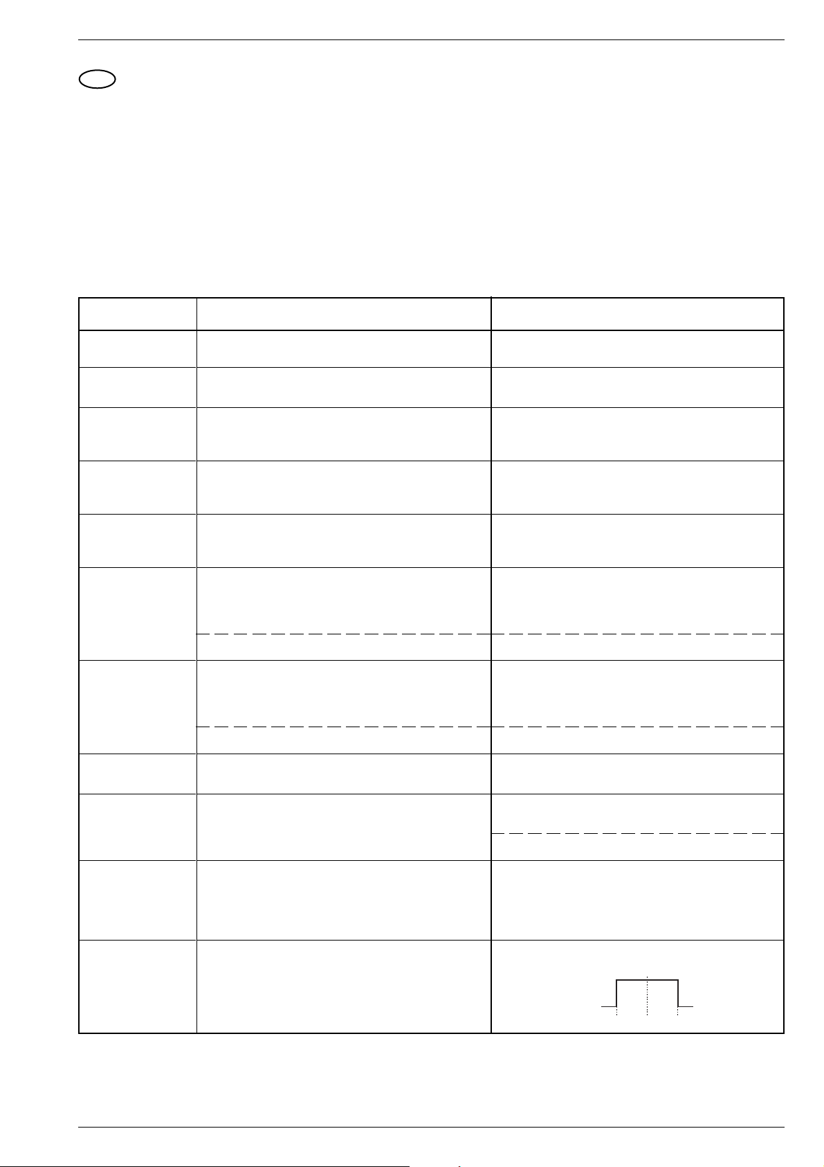
Abgleich Vorbereitung Abgleichvorgang
1. MW-Oszillator
2. LW-Oszillator
3. AM-ZF
4. MW-Vorkreis
5. LW-Vorkreis
6. MW-Suchlaufstop
7. LW-Suchlaufstop
MW;
DC-Voltmeter an FMP705.
LW;
DC-Voltmeter an FMP705.
Meßsender an Antenneneingang; Frequenz 1548kHz;
ohne Modulation; E´ = 100µV (40dBµV).
DC-Voltmeter an FMP602.
Meßsender an Antenneneingang;
ohne Modulation; E´ = 100µV (40dBµV).
DC-Voltmeter an FMP602.
Meßsender an Antenneneingang;
ohne Modulation; E´ = 100µV (40dBµV).
DC-Voltmeter an FMP602.
Meßsender an Antenneneingang;
Frequenz 1008kHz; ohne Modulation.
Extended Expert Modus aktivieren (s. o.).
Signal mit E´ = 250µV (48dBµV) anlegen.
Signal mit E´ = 20µV (26dBµV) anlegen. DX aktivieren.
Meßsender an Antenneneingang;
Frequenz 207kHz; ohne Modulation.
Extended Expert Modus aktivieren (s. o.).
Signal mit E´ = 250µV (48dBµV) anlegen.
Mit L606A bei 531kHz auf 1,0V ±50mV abgleichen.
Kontrolle: 7,0V ± 0,5V bei 1602kHz.
Mit L607AL bei 153kHz auf 1,3V ±50mV abgleichen.
Kontrolle: 5,0V ± 0,5V bei 279kHz.
Mit L604A auf maximale Spannung abgleichen.
Wechselweise mit C608A bei 1548kHz und mit L601A bei
558kHz auf maximale Spannung abgleichen.
Mit L602AL bei 162kHz auf maximale Spannung abgleichen.
Parameterwert 01 solange ändern bis Suchlauf gerade
stoppt.
Parameterwert 00 solange ändern bis Suchlauf gerade
stoppt.
Parameterwert 03 solange ändern bis Suchlauf gerade
stoppt.
Signal mit E´ = 20µV (26dBµV) anlegen. DX aktivieren.
8. FM-Oszillator
9. FM-HF- und ZFKreise
10. ZF-Mitten-
frequenz
11. Stop-Generator
4 GRUNDIG Service
FM;
DC-Voltmeter an FMP705.
Meßsender an Antenneneingang; Frequenz 94,8MHz;
ohne Modulation; E´ = 100µV (40dBµV).
DC-Voltmeter zwischen FMP101 (+) und FMP103 (-).
Meßsender an Antenneneingang; Frequenz 98,0MHz;
f
= 1kHz; Hub = 22,5kHz; E´ = 1mV (60dBµV).
mod
NF-Voltmeter an FMP101.
Extended Expert Modus aktivieren (s. o.).
Parametersatz 68 anwählen.
Wobbler an Antenneneingang; Mittenfrequenz 95,0MHz;
∆f = ± 100kHz; ohne Modulation; E´ = 100µV (40dBµV).
Oszilloskop an FMP104.
Parameterwert 02 solange ändern bis Suchlauf gerade
stoppt.
Mit L06 bei 87,5MHz auf 1,6V ±50mV abgleichen.
Kontrolle: 6,5V ± 0,5V bei 108MHz.
Wechselweise mit L03 und L04 auf Maximum abgleichen.
Mit L05 auf Maximum abgleichen.
Durch Ändern des Wertes auf minimale Anzeige (≤ 10mV)
am NF-Voltmeter einstellen.
Mit L 101 auf symmetrischen Spannungssprung einstellen.
95.0MHz
+5V
0V
∆f≤ ± 45kHz
MS 502
EMK
Rg
50Ω
Kabel
50Ω
10Ω 45Ω
10nF
60Ω
75Ω
E´
E´= EMK - 6dB
FM
Abgleichvorschriften / Adjustment Procedures
Abgleich Vorbereitung Abgleichvorgang
12. Feldstärke
Meßsender an Antenneneingang; Frequenz 95,0MHz; ohne
Modulation; E´ = 70µV (37dBµV).
DC-Voltmeter zwischen FMP101 (+) und FMP103 (-).
13.Stereo-Übersprechen
Meßsender mit Stereo-Coder an Antenneneingang;
Frequenz 94,8MHz;
f
1kHz mit 22,5kHz Hub;
mod
Pilotton 19kHz mit 7,5kHz Hub;
RDS 57kHz mit 1,2kHz Hub; E´ = 1mV (60dBµV).
Nur linken Kanal modulieren.
NF-Voltmeter an Lautsprecher-Ausgang rechter Ka-
nal.
Extended Expert Modus aktivieren (s. o.).
Parametersatz 73 anwählen.
14.FM-Suchlaufstop
Meßsender an Antenneneingang; Frequenz 95,0MHz; ohne
Modulation.
Extended Expert Modus aktivieren (s. o.).
Signal mit E´ = 80µV (38dBµV) anlegen. DX deaktivieren.
Signal mit E´ = 8µV (18dBµV) anlegen. DX aktivieren.
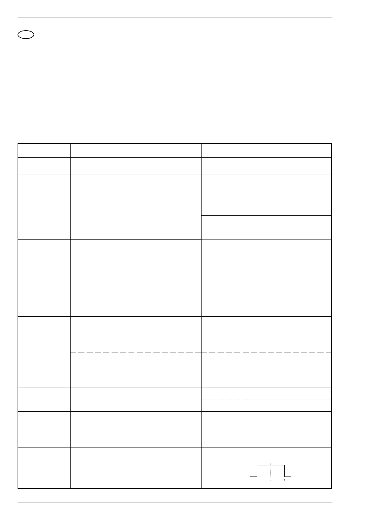
2. Cassettenlaufwerk
Meßgeräte: Frequenzzähler, Test-Cassette 3150Hz (z.B. 448A)
Mit CR26 auf +300mV ± 10mV einstellen.
Durch Ändern des Wertes auf minimale Anzeige einstellen.
Parameterwert 05 solange ändern bis Suchlauf gerade
stoppt.
Parameterwert 04 solange ändern bis Suchlauf gerade
stoppt.
Abgleich Vorbereitung Abgleichvorgang
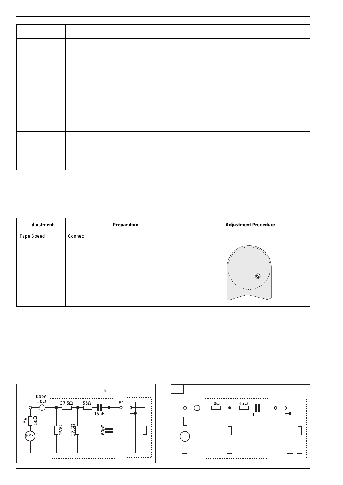
Bandgeschwindigkeit Frequenzzähler an Lautsprecher-Ausgang anschließen.
Test Cassette 3150Hz abspielen.
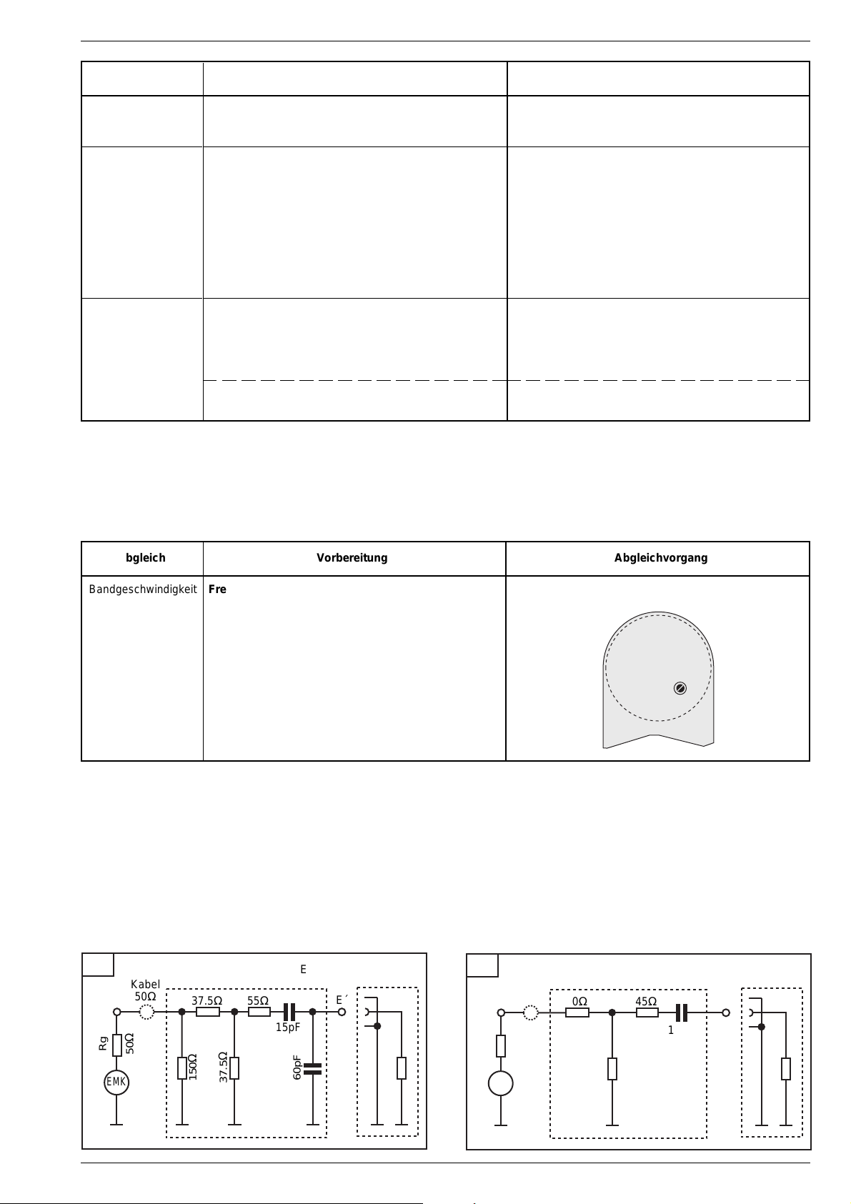
Zum Abgleich die Antennennachbildungen für AM bzw. FM verwenden
AM
E´= EMK - 26dB
Kabel
50Ω
Rg
50Ω
EMK
37.5Ω 55Ω
150Ω
37.5Ω
15pF
E´
60pF
Mit Motorpoti auf 3150Hz einstellen.
Motorpoti
PCB
GRUNDIG Service
5
Abgleichvorschriften / Adjustment Procedures
Abgleichlageplan / Alignment Layout
BU1301
BU1201
MS 502
IC1601V
L2001
BU1202
19373-468.00(01)4B
Q802
L604A
F601A
FMP
602
Q701
L606A
L607AL
Q201
FMP
705
FMP
104
C608A
L601A
L602AL
L101
FMP
103
10
CIC101
11 20
F03
F02
F102
IC2001
FMP
101
1
CR26
L06
F01
L05
L04
L03
BU1203
BU1101T
6 GRUNDIG Service
MS 502
GB
Adjustment Procedures
Abgleichvorschriften / Adjustment Procedures
1. Main Board
Test equipment: DC Voltmeter, Test Generator, AF Voltmeter, Stereo Coder, Sweep Generator, Oscilloscope
Calling up the ´extended Expert Mode´:
Switch off the set. Press and hold depressed station button 2 and switch on the set. Hold the station button 2 depressed for more than 10 seconds.
Press and hold depressed the GEO button for about 4 seconds until the display shows SKODA - XX (XX = version number). Press button TP for more
2 seconds. The display will show PAR. With the buttons 5 resp. 6 select the corresponding parameter set (display shows e.g. PAR 05). Press button
TP briefly (display changes from PAR to CH). With the buttons 5 resp. 6 change the value. Press button TP briefly (display shows PAR again).
If you changed an other parameter by mistake you can find its correct value in the parameter table on page 9.
Set DX to ON: Let the station search pass a complete search at least twice without an input signal.
Adjustment Preparation Adjustment Procedure
1. MW Oscillator
2. LW Oscillator
3. AM IF
4. MW Bandpass
5. LW Bandpass
6. MW search level
stop
7. LW search level
stop
MW;
Connect a DC Voltmeter to FMP705.
LW;
Connect a DC Voltmeter to FMP705.
Connect a Test Generator to aerial input;
Frequency 1548kHz; no modulation; E´ = 100µV (40dBµV).
Connect a DC Voltmeter to FMP602.
Connect a Test Generator to aerial input;
no modulation; E´ = 100µV (40dBµV).
Connect a DC Voltmeter to FMP602.
Connect a Test Generator to aerial input;
no modulation; E´ = 100µV (40dBµV).
Connect a DC Voltmeter to FMP602.
Connect a Test Generator to aerial input;
Frequency 1008kHz; no modulation;
Call up the extended expert mode (see above).
Apply a signal with E´ = 250µV (48dBµV).
Apply a signal with E´ = 20µV (26dBµV). Set DX to ON.
Connect a Test Generator to aerial input;
Frequency 207kHz; no modulation;
Call up the extended expert mode (see above).
Apply a signal with E´ = 250µV (48dBµV).
Apply a signal with E´ = 20µV (26dBµV). Set DX to ON.
Align with L606A at 531kHz for 1.0V ±50mV.
Check: 7.0V ± 0.5V at 1602kHz.
Align with L607AL at 153kHz for 1.3V ±50mV .
Check: 5.0V ± 0.5V at 279kHz.
Align with L604A for maximum voltage.
Align alternating with C608A at 1548kHz and with L601A at
558kHz for maximum voltage.
Align with L602AL at 162kHz for maximum voltage.
Change Parameter value 01 until search just stops.
Change Parameter value 00 until search just stops.
Change Parameter value 03 until search just stops.
Change Parameter value 02 until search just stops.
8. FM Oscillator
9. FM RF and IF
10. IF Center
frequency
11. Stop Generator
GRUNDIG Service
FM;
Connect a DC Voltmeter to FMP705.
Connect a Test Generator to aerial input;
Frequency 94.8MHz; no modulation; E´ = 100µV (40dBµV).
Connect a DC Voltmeter between FMP101 (+) and
FMP103 (-).
Connect a Test Generator to aerial input; Frequency
98.0MHz; f
Connect an AF Voltmeter to FMP101.
Call up the extended expert mode (see above).
Select parameter 68.
Connect a sweep generator to aerial input.
Center frequency 95.0MHz; ∆f = ± 100kHz; no modulation;
E´ = 100µV (40dBµV);
Connect an Oscilloscope to FMP104.
= 1kHz; Hub = 22.5kHz; E´ = 1mV (60dBµV).
mod
Align with L06 at 87.5MHz for 1.6V ±50mV.
Check for 6.5V ± 0.5V at 108MHz.
Align alternating with L03 and L04 for maximum.
Align with L05 for maximum.
Set the parameter value for minimum AF voltage (≤
10mV).
Align L 101 for a symmetrical stop impulse.
95.0MHz
+5V
0V
∆f≤ ± 45kHz
7
Abgleichvorschriften / Adjustment Procedures
Adjustment Preparation Adjustment Procedure
MS 502
12. Field strength
Connect a Test Generator to aerial input; Frequency
95.0MHz; no modulation; E´ = 70µV (37dBµV).
Connect a DC Voltmeter between FMP101 (+) and
FMP103 (-).
13. Stereo Crosstalk
Connect a Test Generator via a Stereo Coder to aerial
input;
Frequency 94.8MHz;
f
1kHz at 22.5kHz dev.;
mod
Pilot 19kHz at 7.5kHz dev.;
RDS 57kHz at 1.2kHz dev.; E´ = 1mV (60dBµV);
modulate only the left channel.
Connect an AF Voltmeter to loudspeaker output right
channel.
Call up the extended expert mode (see above).
Select parameter 73.
14. FM search level
stop
Connect a Test Generator to aerial input; Frequency
95.1MHz; no modulation;
Call up the extended expert mode (see above).
Apply a signal with E´ = 80µV (38dBµV) . Set DX to OFF.
Apply a signal with E´ = 8µV (18dBµV). Set DX to ON.
2. Cassette Drive
Test equipment: Frequency Counter, Test Cassette 3150Hz (e.g. 448A)
Adjust with CR26 for +300mV ± 10mV.
Set the parameter value for minimum AF voltage.
Change Parameter value 05 until search just stops.
Change Parameter value 04 until search just stops.
Adjustment Preparation Adjustment Procedure
Tape Speed Connect Frequency Counter to Loudspeaker Output.
With Motorpoti adjust for 3150Hz.
Play Test Cassette 3150Hz.
Motorpoti
PCB
For adjustment use the aerial dummies for AM resp. FM
AM
Kabel
50Ω
37.5Ω 55Ω
E´= EMK - 26dB
E´
FM
Kabel
50Ω
10Ω 45Ω
E´= EMK - 6dB
E´
15pF
Rg
50Ω
150Ω
EMK
8 GRUNDIG Service
37.5Ω
60pF
Rg
EMK
50Ω
60Ω
10nF
75Ω
MS 502
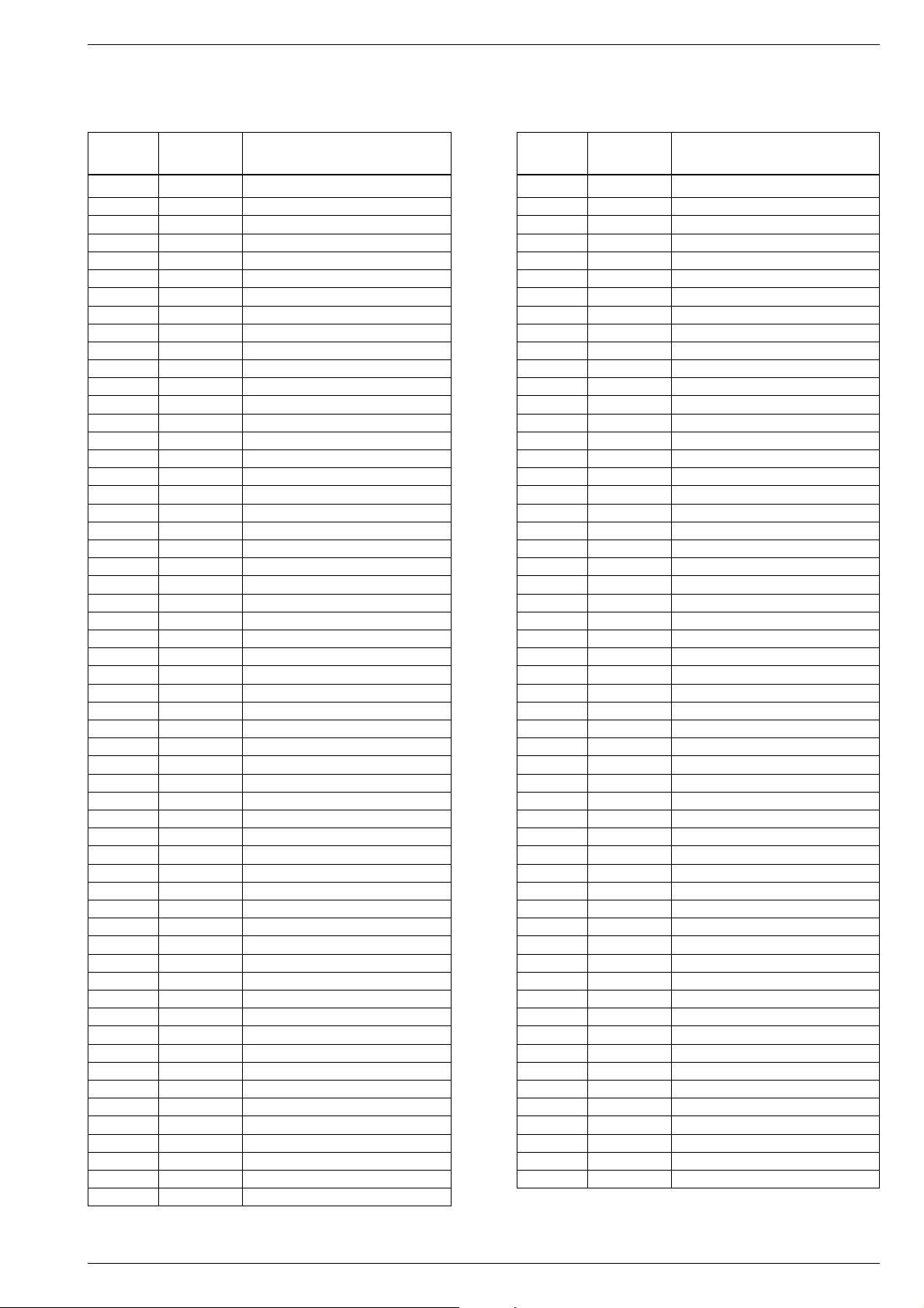
Parametertabelle / Set of Parameters
Abgleichvorschriften / Adjustment Procedures
Parameter Wert Beschreibung
Value Description
00 MW Schwelle DX
01 MW Schwelle LOCAL
02 LW Schwelle DX
03 LW Schwelle LOCAL
04 FM Schwelle DX
05 FM Schwelle LOC
06 3700
07 2880
08 2620
09 2620
10 2660
11 2460
12 2260
13 1860
14 1860
15 3040
16 2260
17 500
18 600
19 300
20 400
21 3580
22 3380
23 3040
24 2660
25 2260
26 2460
27 2260
28 3
29 150
30 25
31 50
32 60
33 50
34 60
35 50
36 60
37 255
38 5
39 80
40 80
41 15
42 30
43 50
44 80
45 100
46 31
47 224
48 16
49 224
50 24
51 1
52 0
53 60
54 75
55 15
56 5
Parameter Wert Beschreibung
Value Description
57 126
58 248
59 21
60 231
61 239
62 133
63 112
64 33
65 126
66 132
67 162
68 ZF-Mitteneinstellung / IF center
69 4
70 4
71 3
72 7
73 Übersprechen / Stereo Crosstalk
74 40
75 0
76 250
77 16
78 10
79 2
80 1
81 0
82 5
83 10
84 4
85 4
86 62
87 25
88 0
89 0
90 2
91 23
92 51
93 20
94 4
95 4
96 4
97 4
98 12
99 0
100 4
101 6
102 8
103 12
104 35
105 25
106 2
107 2
108 2
109 3
110 4
111 75
112 6
GRUNDIG Service
9
Schaltpläne und Druckplattenabbildungen / Circuit Diagrams and Layout of PCBs
L
603
O
A
MS 502
Schaltpläne und Druckplattenabbildungen / Circuit Diagrams and Layout of PCBs
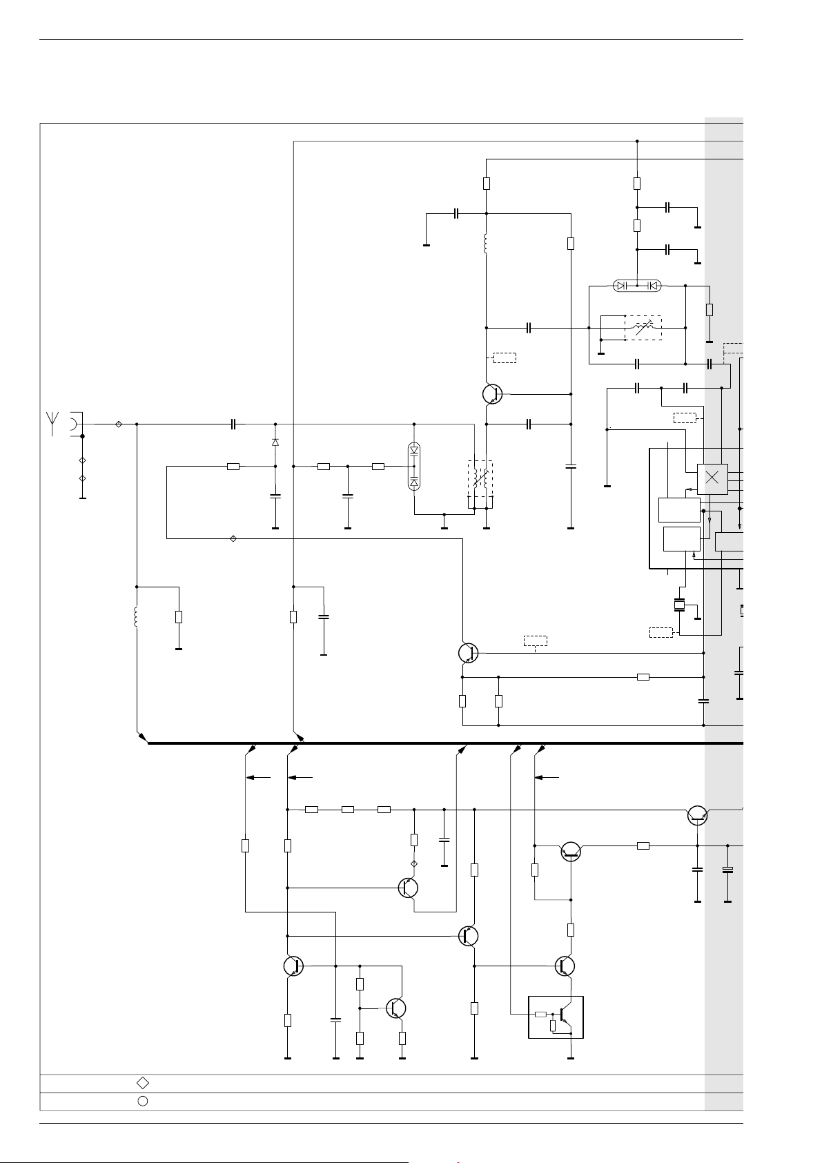
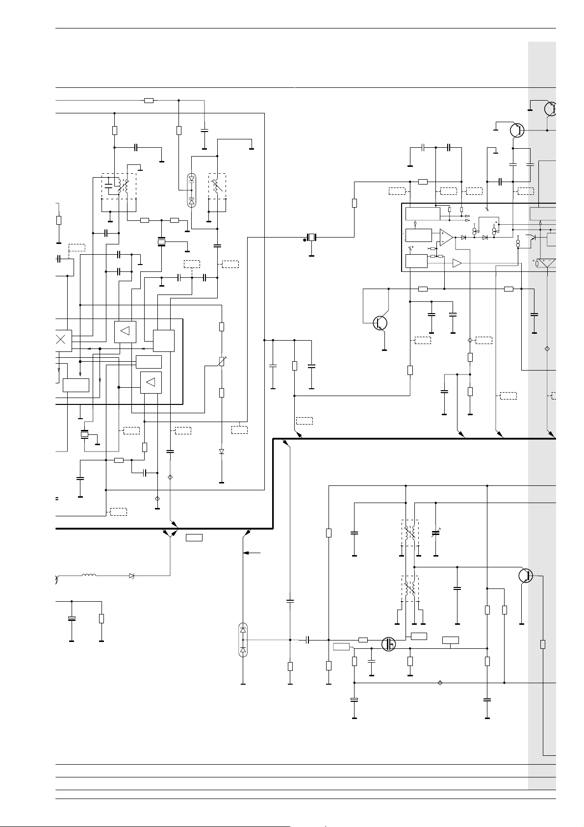
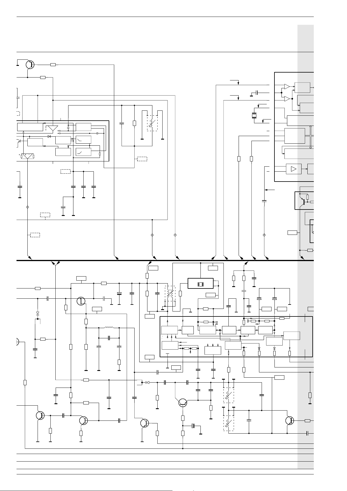
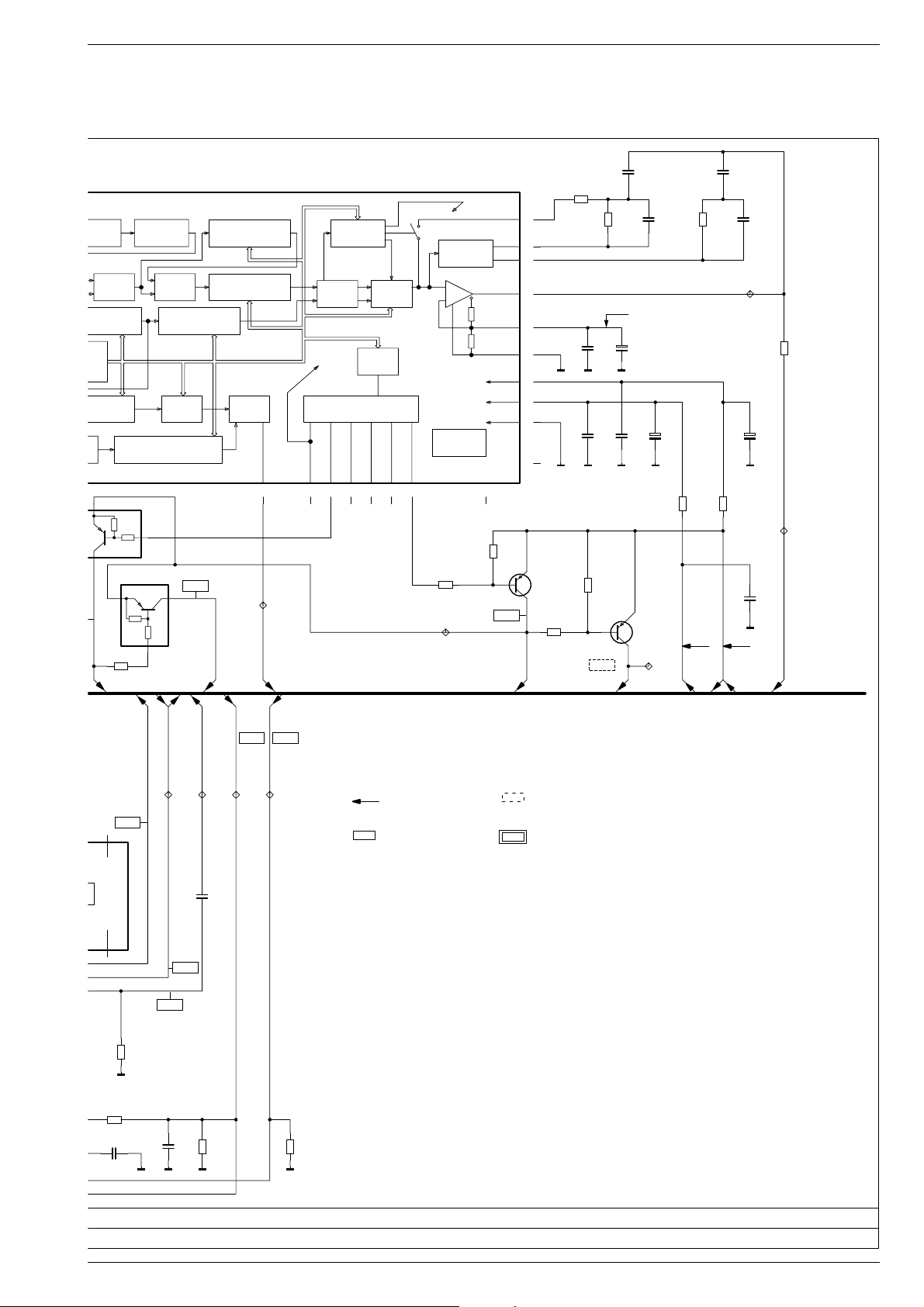
HF-Teil / RF Part
ANT
AN1
FMP01
FMP02
FMP03
2UH2
* CL01
AM-ANT
* CR06
603
470R
CR11
CC17
805
1N0
NP0
603
* CR12
47K
MISCHTEIL
MIXER SECTION
* CL02
2UH2
8140-516-057
* CC16
4P7
603
5V1
* CT01
BFR93AR
* CC02
805
3P3
BA779
* CR01
603
22R
FMP04
603
330K
* CD02
* CC04
CR08
603
10K
805
1N0
NP0
603
10R
* CR07
* CC07
805
1N0
CC08
NP0
805
1N0
CR09
603
47K
CD03
L03
BB804
134678
* CC13
27P
805
805
1N0
* CC12
NP0
8V55
CT02
BC858C
87.5MHz -> 1.6V
108 MHz -> ca.6.5V
CR34
805
805
680R
CR36
680R
CD04
413
NP0
NP0
* CIC01
603
10K
CR13
CC18
1N0
NP0
603
47K
CR14
CC19
12P
BB804
L04
CC21
805
1P0
CC22
805
1N0
WIDE BAND
12 11 10 9 8
1V3
CR33
603
330K
805
603
2
* CC24
CC23
603
6P8
3V6
U4065B
AGC
& IF
INTER-
FERENCE
MIXER
1
F02
2
3
CC43
603
* CR16
1N0
NP0
MIXER
603
805
100N
56K
3V6
1716151413
IF &
DETECT
F03
31
CC42
FM/AM-ABST
01
MESSPUNKTE
+G
+A
5V 14V 14V
PHANTOM
* CR2412P
* CR2411P
805
3R3
2%
603
* CR2408P
* CT2412P
0302
10K
BC848C
2%
603
10K
CR2404P
2%
603
10K
* CR2409P
805
3R3
603
* CC2403P
* CR2413P
10N
* CR2414P
* CR2418P
805
3R3
2%
603
33K
2%
603
10K
FMP2401
* CR2405P
240104
603
* CR2407P
* CT2411P
2%
603
1K6
2%
10K
* CC2404P
* CT2409P
BC858C
BC848C
603
100N
603
10K
* CR2403P
* CT2408P
BC858C
603
10K
* CR2406P
+A
ANT-ON
* CR2415P
603
10K
47K
* CT2404P
BC858C
* CR2420P
47K
603
47K
* CT2406P
BC848C
* CT2407P
BCR135
* CR2416P
603
1K0
T2401P
BC368
* CC2401P
+
603
100N
C2402P
SP
ABGLEICHPUNKTE
10 GRUNDIG Service
10U/16V
MS 502
4
8
H
U
G
-
CD602A
100N
603
Schaltpläne und Druckplattenabbildungen / Circuit Diagrams and Layout of PCBs
CR19
603
470R
603
15R
CR18
CC29
603
22N
432
876
1
CR22
470R
603
CC27
603
100N
CC26
603
4P7
CR23
603
F01
603
820R
1
2
3
* CC34
C24
1N0
NP0
L05
603
56K
CC28
180P
3V6
805
242322212019181716
MIXER
IF &
DETECTOR
IF1
VOLTAGE
REG.
IF2
LOCAL
OSCI
987654321
CC42
F03
1
2
3
603
100N
0V7 2V1
603
330R
CR31
CR32
603
22R
CC41
603
22N
* CC39
FMP06
CR21
22P
805
NP0
1N0
* CT10
BC84
CC106
603
10N
* CIC101
CR117
3V1
MPX
CT103
BC848C
CC107
603
33K
100N
100N
CC108
603
603
2V3 1V8 1V8 1V8
151617181920
ABSTIMM
STOP-LO
ST
SC
22N
CC114
603
FMP102
1
K-SIGNAL
FM-ZF
CC104
22N
CR112
603
120R
FM IF
603
CC103
22N
603
805
603
10K
CC31
NP0
1N0
2
L06
BB804
CD05
603
2V6
413
* CC36
603
47P
* CR26
* CC33
603
CR24
* CR28
* CD06
603
603
6P8
3V2
1K2
500mV
4K7
4K3
BAS16
7V8
CC37
NP0
1N0
805
8602-222-190
1
805
C38
4R7
* CR27
9V1
+FM
AM-ANT
F102
3
2
+
22U/16V
603
CR111
180R
AM-TEIL
AM SECTION
ZFVERSTAERKER
PEGELDETEKTOR
TDA
1593T
8305-841-593
ST
U
UREF
1 23456
CR121FK
603
12K
+
22N
CT102FK
BC848C
805
* CR122
10R
CC118
603
C117
* CC116
10U/16V
2V4 8V9
FMP101
603
1K8
* CR118
603
6N8
8K2
603
* CR124
FELDST
MW 531 KHZ - 1602 KHZ
LW 153 KHZ - 279 KHZ
*
100N
8V85
FMP05
FM-OSZ
ca.
12V0
AM-ANT
+
C2402P
L2401P
1MH0
10U/16V
603
68K
CR2417P
CD2401P
Z47
SPANNUNGSVERSORGUNG FUER AKTIVANTENNE
VOLTAGE SUPPLY FOR ACTIVE AERIAL (DC)
CD601A
BAV99
+S
9V2
805
CC602A
603
CR602A
1N0
CC603A
820K
1N0
34
603
CC607A
CR606A
100R
603
* CR607A
+
100N
603
1M0
* CC606A
10U/16V
L601A
MW
L602AL
LW
* CT601A
G1
G2 S
BF992A
603
47N
C608A
5P5-30P
781
6
34
603
12P
CC611AL
781
6
NP0
* CR612A
8V0
D
603
* CR608A
270R
2V8
* CR613A
FMP601
* CC612A
CT602AL
BC818/40
CC616A
603
603
22K
2K7
* CR614A
603
1K8
CR616AL
603
330R
603
100N
603
1M0
CR603A
805
7V2
603
560K
CR604A
C604A
6010605
GRUNDIG Service
11
Schaltpläne und Druckplattenabbildungen / Circuit Diagrams and Layout of PCBs
7
4
CC114
2K2
A
1
4
* CT104
BC848C
100N
603
ABSTIMMSTOP-LOGIK
STUMMSCHALTUNG
678
* CR113
603
10K
* CR114
FM-AUS
603
47K
VERSTIMMDETEKTOR
KLIRRFAKTKOMP.
2V1
L101
1378
1112131415
603
1K8
QUADRATUR
DEMOD.
50khz
1MHZ
CC109
100P
CR116
603
4V2
910
3V4
3V4
603
CR701
10K
CC701
Q701
603
* CR702
22N
10K
603
2V3
10MHz25
2V3
MS 502
FM_IN
24
19
25
AM_IN
9
OSCIN
OSCOUT
10
ADDR
20
SCL
12
SDA
13
IF_AM
14
IF_FM
15
HFREF
REF.OSCILLATOR
I2C BUS
INTERFACE
14 BIT PROG.CNT
SWITCH
AM/FM
SWITCH
SWM/DIR
L
22N
603
FMP102
K-SIGNAL
603
1K8
CR616AL
1V25
* CR627A
603
10R
CD602A
CR624A
603
CC616A
4V0
CC617A
1N0
KV1561
603
47K
100N
* CT603A
BC848C
* CR618A
CC119V
603
MW 1,0V - ca. 7V
LW 1,3V - ca. 5V
FM/AM-ABST
805
* CR626A
603
100N
* CC614A
* CC613A
603
10N
603
100K
100N
603
1M0
CR623A
* CR622A
CC113
* CT606A
603
22R
603
2K7
100N
CC112
603
8V1
BF543
GSD
CR633A
* CR621A
603
* CR619A
100N
603
603
150R
* CR629A
603
47R
* CR631A
603
3K3
603
680K
* CT604A
BC848C
180R
CC111
0V75
68N
805
* CR628A
CC618A
100N
603
* CC623A
603
10R
* CL603A
* CC622A
2N7
MPX(RDS)MUTE
+
C619A
1N0
805
* CC624A
* CR632A
603
100N
* CC628A
1N0
603
603
805
47U/10V
4N7
10R
603
5UH6
CC626A
603
CC621A
CC627AL
CT607AL
BC818/40
100N
603
22N
+AM
603
CR634A
603
* CR636A
8V2
8V2
CD603A
KV1561
3V4
603
10N
* CC704A
FMP103
UREF
22R
47K
* CC629A
22N
CR639A
CR641AL
FMP104
AM-OSZ
* CR653A
603
47N
CC631A
BALANCED
FULL-WAVE
CONTROLLED
OSCILLATOR
603
22R
* CR646A
1378
8140-535-116
1378
603
MW
L606A
LW
L607AL
SCL
AM-NF
10K
* CR638A
* CC635A
3K525R
AF PRE-
AMPLIFIER
* CR647A
603
603
FM-STOP
FM-OSZ
2V1 9V1
21F601A
4
L604A
1206
2N2 NP0
603
CR637A
781346
DOUBLE
BALANCED
MIXER
+
GAIN-
CONTROLLED
RF STAGE
20 19 18 17 16 15 14 13 12 11
4V0
*CC637A
603
CC638A
603
100N
NP0
603
47K
* CR643AL
603
10K
CR642AL
E
1K8
STANDBY
SWITCH
VR(AGC)
V1
CC641A
805
180P
* CT608AL
BC818/40
603
22K
C644AL
+
10U/16V
603
2K2
GND
A2
A1
3
2V1
CR645A
603
5K6
3K
V2
VR(AGC)
GAIN CON-
TROLLED IF
AMPLIFIER DETECTOR
V1 V2 V3
INTERNAL
SUPPLY
VOLTAGES
603
603
22N
NP0
33P
* CC646A
270P
805
* CC643AL
603
22K
100N
NP0
CC639A
805
CC642AL
* CR644AL
SDA
4K7
* CC633A
805
220N
603
CC632A
V3
0R
603
CC649A
7K
VR
NP0
603
C634A
22N
120P
FMP701
AM-ZF
15N
+
1U0/50V
0V5 1V4
7K
AGC
AMPLIFIER
V3
170R
603
22P
CC648A
C636A
INDIKATOR
DRIVER
* CT704AL
DTA143ZK
+
10U/16V
220R
4V1
CT609AL
BC848C
12K
8305-841-572
TDA1572T
AMPLIFIER
9V1
IF
* CIC601A
50R
* CR709
+MW
10987654321
CR649AL
* CC652A
n. c.
n. c.
603
47K
100N
100K
47K
4K
603
4V
603
* CR648A
603
701104103102101
12 GRUNDIG Service
MS 502
+MW
Schaltpläne und Druckplattenabbildungen / Circuit Diagrams and Layout of PCBs
SWITCH
AM/FM
S
CE
ROG.CNT
PRECOUNTER
:32/33
SWITCH SWITCH
SWM/DIR SWM/DIR
11 - 21 BIT PROG.CNT
47K
4K7
47K
* CR709AL
603
100K
4K7
16 BIT PROG.CNTOSCILLATOR
9V1
* CT703AL
DTA143ZK
AM-FM PLL
5 BIT PROG.CNT
11 BIT PROG.CNT
+LW
SSTOP
FMP702
AM-STOP
INLOCK
DOUT1
INLOCK
DETECTOR
PORT EXTENSIONCONTROLTIMER
DOUT3
DOUT2
567816 17 18
TEST
LOGIC
DOUT4
* CC716A
603
100K
* CR707A
Loop AMLoop FM
603
22R
* CR703
5V 9V2
+S
805
603
68N
* CC715A
FMP706
C706
47R
CC705
603
+
6N8
22U/16V
805
1N0
NP0
805
220R
* CR708
FMP705
FM/AM-ABST
603
10N
603
8K2
CC712
CC708
* CR714A
* CC714
805
603
* CR706
27K
* CC713
1N0
2V4
+
603
100N
C711
10U/16V
CC709
+FM
603
47N
* CT701A
FMP704
+
C707
BC808/40
100U/10V
CR704
+G
805
1N0
NP0
603
47K
9V1
2
1
3
28
4
26
27
21
22
23
* CT702A
BC808/40
* CR713A
603
4K7
* CR705
INLOCK
LPHC
VDD1
NC
11
* CR712A
LPFM
LPAM
LPOUT
VREF
GNDAN
VDD2
VDD1
GNDDIG
NC
603
47K
9V1
SWITCH
LP1/LP2
* CIC701
TDA7427D
8305-847-428
DOUT6
* CR711A
FMP703
+
POWER ON
RESET
603
4K7
CHARGEPHASE
PUMPCOMP
DOUT5
+AM
10
n. c.
IC601A
n. c.
11
CR649AL
* CC652A
100N
* CR648A
603
47K
4V4
603
603
2K2
AM-ZF
0V7
CC653AL
FELDST
FMP602
0V2
603
22N
AM-OSZ
FMP603
603
4N7
* CC654A
603
3K3
CR651AL
+MW
9V1 9V1
FMP604
+LW
FMP605
603
100K
CR652AL
ALLE SPANNUNGEN SIND NÄHERUNGSWERTE, GEMESSEN BEI UB=14V GEGEN MINUS
ALL VOLTAGES ARE APPROXIMATES, MEASURED AT UB=14V WITH RESPECT TO NEGATIV
OHNE SIGNAL
WITHOUT SIGNAL
OHNE SIGNAL:AM
WITHOUT SIGNAL:AM
OHNE SIGNAL:FM
WITHOUT SIGNAL:FM
MIT SIGNAL:TB
WITH SIGNAL:TR
HAUPTPLATTE
MAIN BOARD
19373-215.00
* = BAUTEILE REFLOWSEITE
GRUNDIG Service
19.05.99
702605604603602
703
704 706 705
13
Schaltpläne und Druckplattenabbildungen / Circuit Diagrams and Layout of PCBs
Klangsteller / Sound Control
MS 502
CC301FS
603
47P
603
* CC302FS
603
10K
* CR302FS
150P
* CR304FS
CR303FS
603
47K
* CC303FS
150P
603
5K6
CR301FS
603
603
10K
603
* CR306FS
+
C304FS
* CR307FS
603
1K0
22K
10U/16V
* CT301FS
603
18P
* CC306FS
603
10K
CR308FS
BC848C
* CT302FS
10N
603
* CC307FS
603
2K2
CR309FS
BC858C
603
10K
* CR311FS
603
1K0
* CR312FS
10N
CC308FS
603
* CC309FS
603
100N
FMP301
603
10K
* CR317FS
603
* CR313FS
UR
* CT303FS
100K
BC858C
10N
CC317FS
603
+S
9V2
CR321FS
603
10K
MPX2
* CC312
603
3K3
* CR316FS
UHCC
CT305FS
* CR314
68P
603
* CC313FS
FMP302
603
4K7
603
BC858C
100P
MPX
FMP201
DYN.HC
4N7
CC318FS
603
PAUSE
MPX(RDS)MUTE
+S
MESSPUNKTE
303
302301
15021501201
ABGLEICHPUNKTE
14 GRUNDIG Service
 Loading...