

Page 1
HiFi Service Manual
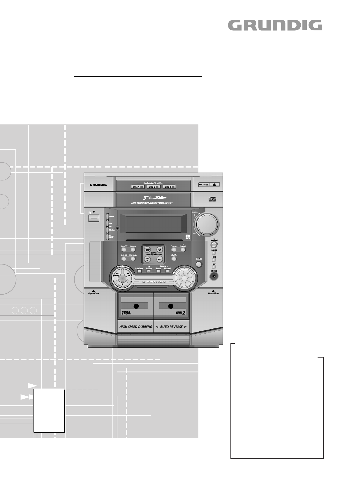
MS 4101
GLM0150
Zusätzlich erforderliche Unterlagen für den Komplettservice
Additionally required Service Documents for the Complete Service
Service
Manual
Sicherheit
Safety
Materialnr./Part No.
720108000000
Materialnummer/Part Number 720107717000
Änderungen vorbehalten/Subject to alteration • Printed in Germany • WÜ
E-BS-SA16 1001 • 8002/8012, 8005/8015, 8006/8016
http://www.grundig.com
Grundig Service
Hotline Deutschland…
Technik:
TV
TV
SAT
VCR/LiveCam
HiFi/Audio
Car Audio
Telekommunikation
Planatron
Ersatzteil-Verkauf: Mo.-Fr. 8.00-19.00 Uhr
Kundendienst/Werkstätten:
gebührenpflichtig
(8.00-22.00 Uhr)
…Mo.-Fr. 8.00-18.00 Uhr
0180/52318-41
0180/52318-49
0180/52318-48
0180/52318-42
0180/52318-43
0180/52318-44
0180/52318-45
Fax:
Telefon: 0180/52318-40
Telefon:
Fax:
0180/52318-51
0180/52318-99
0180/52318-50Fax:
Mo.-Fr. 8.00-18.00 Uhr
0180/52318-52
0180/52318-46
Page 2

Allgemeiner Teil / General Section MS 4101
Es gelten die Vorschriften und Sicherheitshinweise gemäß dem Service Manual "Sicherheit",
Materialnummer 720108000000, sowie zusätzlich die eventuell abweichenden, landesspezifischen Vorschriften!
Inhaltsverzeichnis
Seite
Allgemeiner Teil ........................... 1 - 2 … 1 - 13
Messgeräte / Messmittel ............................................................ 1 - 2
Technische Daten ...................................................................... 1 - 3
Servicehinweise ......................................................................... 1 - 3
Ausbauhinweise ......................................................................... 1 - 4
Bedienhinweise .......................................................................... 1 - 9
Abgleichvorschriften ......................2 - 1 ... 2 - 2
Tuner .......................................................................................... 2 - 1
Cassette ..................................................................................... 2 - 2
Schaltpläne und
Platinenabbildungen .................... 3 - 1 … 3 - 28
Schaltpläne:
Haupt-Platte ........................................................................... 3 - 1
NF-Verstärker ......................................................................... 3 - 7
Front-Platte .......................................................................... 3 - 11
CD-Platte .............................................................................. 3 - 15
Tuner .................................................................................... 3 - 19
Netzteil-Platte, Sicherungs-Platte,
Standby Netzteil, Optischer Ausgang .................................. 3 - 23
Platinenabbildungen:
Haupt-Platte ........................................................................... 3 - 5
NF-Verstärker ......................................................................... 3 - 9
Front-Platte .......................................................................... 3 - 13
CD-Platte .............................................................................. 3 - 17
Tuner .................................................................................... 3 - 21
Netzteil-Platte, Sicherungs-Platte,
Standby Netzteil, Optischer Ausgang .................................. 3 - 23
Verdrahtungsplan ..................................................................... 3 - 25
IC-Innenbeschaltungen ............................................................ 3 - 27
The regulations and safety instructions shall be
valid as provided by the "Safety" Service Manual,
part number 720108000000, as well as the respective national deviations!
Table of Contents
Page
General Section ............................ 1 - 2 … 1 - 18
Measuring Instruments / Equipment .......................................... 1 - 2
Technical Data ........................................................................... 1 - 3
Service Hints .............................................................................. 1 - 3
Disassembly Instructions ........................................................... 1 - 4
Operating Hints ........................................................................ 1 - 14
Adjustment Procedures..................2 - 3 ... 2 - 4
Tuner .......................................................................................... 2 - 3
Cassette ..................................................................................... 2 - 4
Circuit Diagrams and
Layout of the PCBs ...................... 3 - 1 … 3 - 28
Circuit Diagrams:
Main Board ............................................................................. 3 - 1
AF Amplifier ............................................................................ 3 - 7
Front Board .......................................................................... 3 - 11
CD Board ............................................................................. 3 - 15
Tuner .................................................................................... 3 - 19
Power Supply Board, Fuse Board,
Standby Power Supply, Optical Output ................................ 3 - 23
Layout of the PCBs:
Main Board ............................................................................. 3 - 5
AF Amplifier ............................................................................ 3 - 9
Front Board .......................................................................... 3 - 13
CD Board ............................................................................. 3 - 17
Tuner .................................................................................... 3 - 21
Power Supply Board, Fuse Board,
Standby Power Supply, Optical Output ................................ 3 - 23
Wiring Diagram ........................................................................ 3 - 25
IC Block Diagrams ................................................................... 3 - 27
Explosionszeichnungen und
Ersatzteilliste .................................. 4 - 1 … 4 - 7
Allgemeiner Teil
Messgeräte / Messmittel
Frequenzzähler Wobbel- / Mess-Sender
Oszilloskop Digital-Voltmeter
Testcassette 3150Hz/10kHz (z.B. 448)
Beachten Sie bitte das GRUNDIG Messtechnik-Programm, das Sie
unter folgender Adresse erhalten:
GRUNDIG AG Geschäftsbereich Instruments
Test- und Mess-Systeme
Würzburger Str. 150
D 90766 Fürth/Bay
Tel. 0911/703-4540
Fax 0911/703-4130
eMail: instruments@grundig.com
Internet: http://www.grundig-instruments.de
Internet: http://www.grundig-instruments.com
Exploded Views and
Spare Parts List .............................. 4 - 1 … 4 - 7
General Section
Measuring Instruments / Equipment
Frequency counter Sweep / Signal generator
Oscilloscope Digital voltmeter
Test cassette 3150Hz/10kHz (e.g. 448)
Please note the GRUNDIG Catalog "Test and Measuring Equipment"
obtainable from:
1 - 2 GRUNDIG Service
Page 3

MS 4101 Allgemeiner Teil / General Section
Technische Daten
Verstärkerteil
Ausgangsleistung:
Sinusleistung ................................................................... 2 x 85W
Musikleistung ................................................................ 2 x 170W
Maximalleistung .................................................................. 850W
Eingangsempfindlichkeit / -Impedanz ........................ 400mV / 22kΩ
Empfangsteil
Empfangsbereich FM ........................................... 87,5 ... 108,0MHz
Empfangsbereich MW ............................................. 522 ... 1611kHz
Empfangsbereich LW ................................................ 144 ... 290kHz
CD Teil
Frequenzgang ........................................................... 20Hz ... 20kHz
Geräuschspannungsabstand (wtd.) ......................................... 85dB
Cassettenteil
Tonträger ..................... Compact-Cassette nach DIN 45516 (IEC I)
Frequenzbereich .................................................... 40Hz ... 12,5kHz
Spurlage ...................................................... Viertelspur international
Geräuschspannungsabstand (wtd.) ......................................... 50dB
Gleichlaufschwankungen (WRMS) ...................................... ±0,25%
Spannungsversorgung
Betriebsspannung .................................................................. 230V~
Netzfrequenz ....................................................................... 50/60Hz
max. Leistungsaufnahme ........................................................ 500W
Leistungsaufnahme in Standby ................................................... 2W
Technical Data
Amplifier unit
Output power:
Sinusoidal power ............................................................. 2 x 85W
Music signal power ........................................................ 2 x 170W
Maximum power .................................................................. 850W
Input sensitivity / impedance ..................................... 400mV / 22kΩ
Receiver unit
Reception range FM ............................................ 87.5 ... 108.0MHz
Reception range MW .............................................. 522 ... 1611kHz
Reception range LW ................................................. 144 ... 290kHz
CD unit
Frequency response ................................................. 20Hz ... 20kHz
Noise voltage ratio (wtd.) ......................................................... 85dB
Cassette unit
Medium ............................. Compact tape acc. to DIN 45516 (IEC I)
Frequency range .................................................... 40Hz ... 12.5kHz
Tracking position ..................................... International quarter-track
Noise voltage ratio (wtd.) ......................................................... 50dB
Wow and flutter (WRMS) ....................................................... 0.25%
Power supply
Operating voltage ................................................................... 230V~
Mains frequency .................................................................. 50/60Hz
Max. power consumption ........................................................ 500W
Power consumption in stand-by mode ........................................ 2W
Abmessungen und Gewicht
Abmessungen Gerät ......................... B x H x T 270 x 332 x 410mm
Gewicht Gerät ........................................................................... 18kg
Abmessungen Lautsprecher ............. B x H x T 220 x 280 x 260mm
Gewicht pro Lautsprecher ........................................................... 4kg
Servicehinweise
Vor Öffnen des Gehäuses Netzstecker ziehen.
Cassettenteil
Überprüfen Sie vor Beginn der Service-Arbeiten, ob die Magnetköpfe,
die Tonwelle und die Gummiandruckrolle frei von Bandabrieb sind.
Zum Reinigen dieser Teile verwenden Sie ein mit Spiritus oder
Reinigungsbenzin getränktes Wattestäbchen; dadurch verbessert
sich der Aufnahme- und Wiedergabepegel, sowie der Bandlauf.
Nach dem Ersatz von Magnetköpfen oder sonstiger Bauteile müssen
die technischen Daten des Gerätes anhand der im Service Manual
vorgegebenen Messwerte überprüft bzw. eingestellt werden.
Leitungsverlegung
Bevor Sie die Leitungen und insbesondere die Masseleitungen lösen,
muss die Leitungsverlegung zu den einzelnen Baugruppen beachtet
werden.
Nach erfolgter Reparatur ist es notwendig, die Leitungsführung wieder
in den werkseitigen Zustand zu versetzen um evtl. spätere Ausfälle
oder Störungen zu vermeiden.
Auswurf einer CD bei defektem Laufwerk
Um bei defektem Schubladenantrieb CDs aus dem Gerät zu nehmen,
muss das Gehäuseoberteil abgenommen werden (Siehe Ausbauhinweise).
Dimensions and weight
Dimensions of device ....................... W x H x L 270 x 332 x 410mm
Weight of device ....................................................................... 18kg
Dimensions of speakers ................... W x H x L 220 x 280 x 260mm
Weight per speaker ..................................................................... 4kg
Service Hints
Disconnect the mains plug before opening the set.
Cassette Section
Before commencing service work, ensure that the magnetic heads, the
capstan and the pinch roller are free from particles produced by tape
abrasion. The recording and playback levels and the tape run can be
improved by cleaning these parts with a cotton-wool tip soaked in spirit
or cleaning benzine.
If the heads or other components have been replaced, the technical
data of the recorder must be checked or adjusted according to the
values specified in the Service Manual.
Wiring
Before disconnecting any leads and especially the earth connecting
leads observe the way they are routed to the individual assemblies.
On completion of the repairs the leads must be laid out as originally
fitted at the factory to avoid later failures or disturbances.
Ejecting a CD when the Drive is defective
To eject CDs from a set having a defective CD tray drive, remove the
cabinet top (see disassembling instructions).
CD-Teil
Bei Ausbau der CD-Lasereinheit muss vor Abziehen
der Steckverbindungen eine Schutzlötstelle auf der
Leiterplatte der Lasereinheit angebracht werden, um
eine Zerstörung der Laserdiode durch statische Aufladung zu vermeiden.
Beim Einbau einer neuen Lasereinheit (CD-Laufwerk) muss nach Einstecken der Steckverbinder
die werkseitig angebrachte Schutzlötstelle entfernt werden!
GRUNDIG Service 1 - 3
Schutzlötstelle
protective soldered joint
CD Section
When removing the Laser pick-up, the Laser pick-up
PCB must be provided with a protective soldered joint
before unplugging the connectors to avoid damage to
the Laser diode by static charges.
When inserting the new Laser pick-up (CD drive
mechanism) the soldered joint fitted at the factory
must be removed after the connectors are plugged
in.
Page 4
Allgemeiner Teil / General Section MS 4101
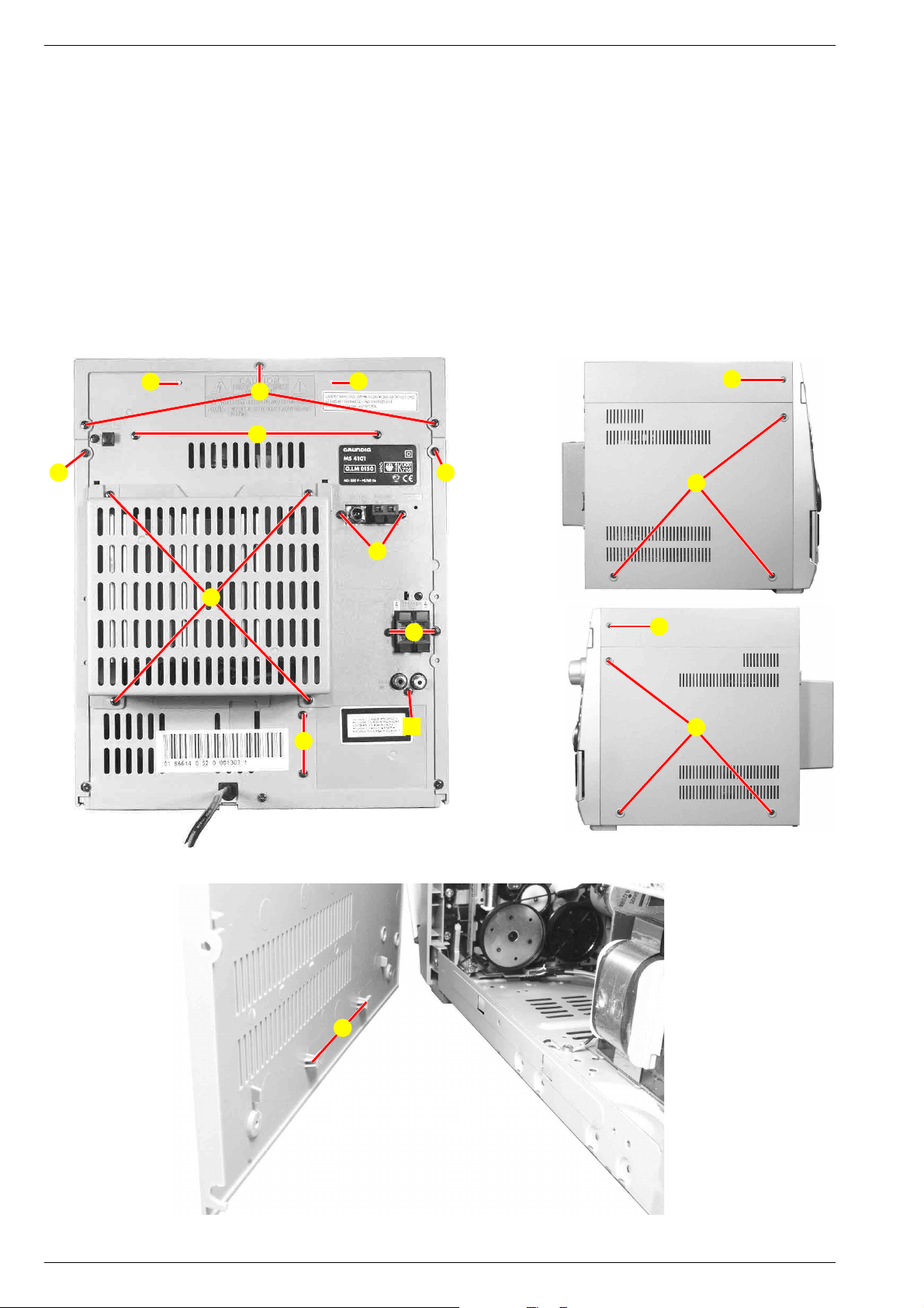
Ausbauhinweise
Bevor Sie Leitungen lösen, muss die Leitungsverlegung beachtet
werden. Nach erfolgter Reparatur ist es notwendig, die Leitungsführung in den werkseitigen Zustand zu versetzen.
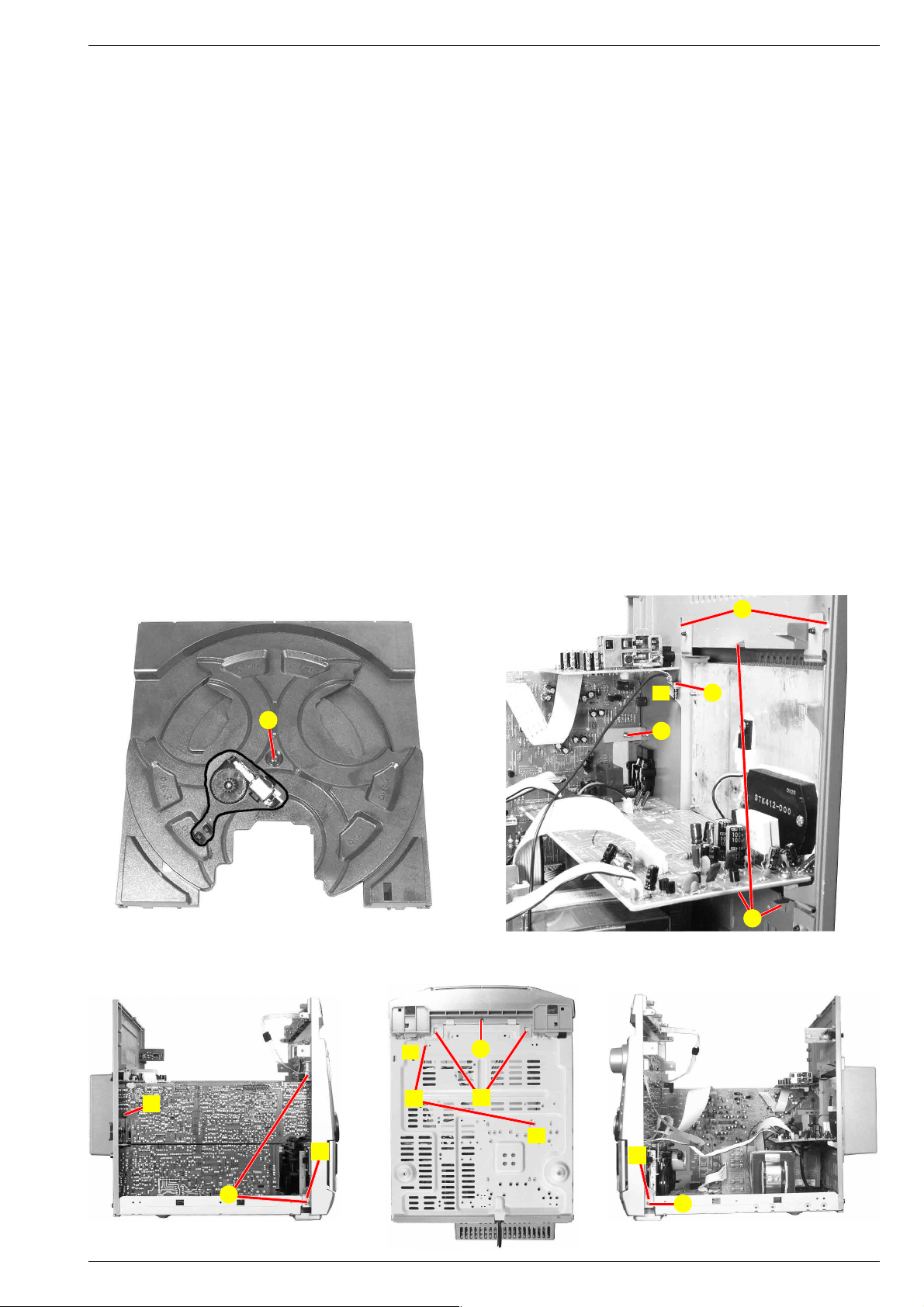
1. Gehäuseoberteil
- 5 Schrauben A (Fig. 1, 2, 3) herausdrehen.
- Gehäuseoberteil hinten anheben und nach oben abnehmen.
2. Gehäuseseitenteile
- 8 Schrauben B (Fig. 1, 2, 3) herausdrehen.
- Gehäuseseitenteile nach hinten schieben und abnehmen.
Beim Einbau die Haken C (Fig. 4) einhängen.
E
A
E
D
B B
Disassembly Instructions
Before disconnecting any leads observe the way they are routed.
On completion of the repairs the leads must be laid out as
originally fitted at the factory.
1. Cabinet Top
- Undo 5 screws A (Fig. 1, 2, 3).
- Lift the cabinet top at the rear side and remove it upwards.
2. Cabinet Sides
- Undo 8 screws B (Fig. 1, 2, 3).
- Move the sides to the rear and remove them.
When reassembling hook in the hooks C (Fig. 4).
A
B
T
Fig. 2
U
U
C
Y
Fig. 1 Fig. 3
A
B
C
Fig. 4
1 - 4 GRUNDIG Service
Page 5
MS 4101 Allgemeiner Teil / General Section
3. CD-Laufwerk
- Gehäuseoberteil (Punkt 1) und Gehäuseseitenteile (Punkt 2) abnehmen.
- CD-Schublade ausfahren (bei defektem Schubladenantrieb siehe
Punkt 3.1).
- CD-Fachblende nach oben abnehmen.
- CD-Schublade einfahren.
- 2 Schrauben D (Fig. 1) herausdrehen.
- Bei Bedarf Steckverbindungen lösen.
- Rückwand nach hinten drücken und Nasen E (Fig. 1) aushängen
- CD-Laufwerk herausnehmen.
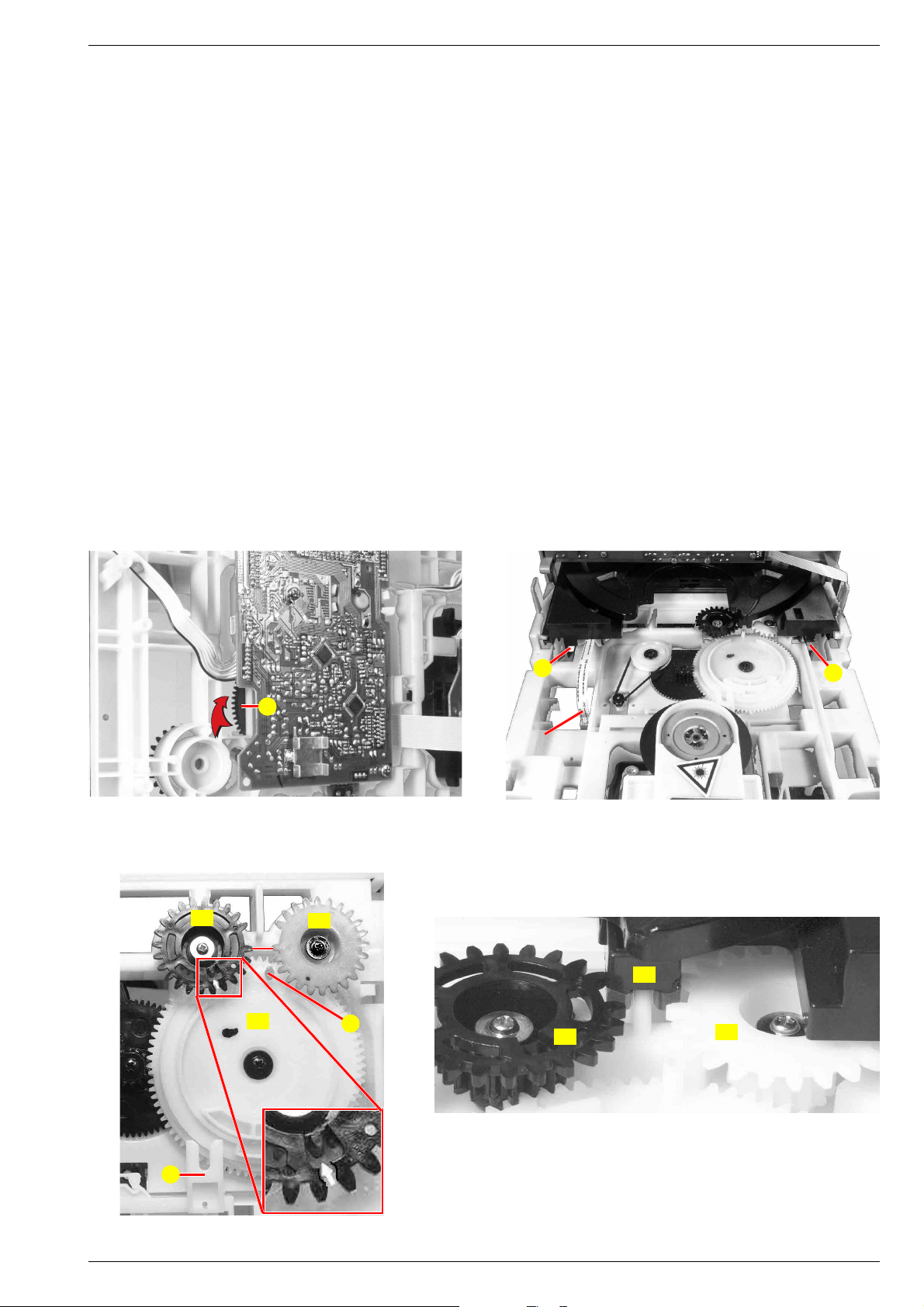
3.1 CD-Schublade manuell ausfahren
- Zahnrad F (Fig. 5) in Pfeilrichtung drehen, bis sich die Schublade
bewegt. Schublade von Hand öffnen.
3.2 CD-Schublade ausbauen
- CD-Schublade ausfahren (bei defektem Schubladenantrieb siehe
Punkt 3.1).
- 5-pol.-Flexprint (Fig. 6) abziehen.
- 2 Raster G (Fig. 6) ausrasten.
- Schublade abnehmen.
Montage:
- Fig. 7: Die Pfeilmarkierung von Zahnrad Z1 muss dem Markierungszahn von Zahnrad Z2 gegenüberstehen. Zahnrad Z3 muss wie
abgebildet zu Zahnrad Z2 ausgerichtet sein.
- Fig. 8: Die Zahnstange Z4 muss in die Lücken der Zahnräder Z2 und
Z3 eingreifen.
- Schublade einschieben. Führung H (Fig. 7) muss in Schieber I
(Fig. 7) eingreifen.
3. CD Mechanism
- Remove the cabinet top (para 1) and the cabinet sides (para 2).
- Open the CD tray (if the tray drive is defective see para 3.1).
- Remove the CD tray cover to the top.
- Close the CD tray.
- Undo 2 screws D (Fig. 1).
- When necessary unplug connectors.
- Move the rear panel backwards to unhook the noses E (Fig. 1).
- Remove the CD mechanism.
3.1 Open CD Tray manually
- Turn toothed wheel F (Fig. 5) in direction of the arrow until the tray
moves out. Open the tray by hand.
3.2 Disassembling the CD Tray
- Open the CD tray (if the tray drive is defective see para 3.1).
- Unplug the 5 pin flexprint (Fig. 6).
- Disengage 2 hooks G (Fig. 6).
- Remove the tray.
Mounting:
- Fig. 7: The arrow mark of toothed wheel Z1 must face the mark of
toothed wheel Z2. Toothed wheel Z3 must be oriented to toothed
wheel Z2 as shown in Fig. 7.
- Fig. 8: The toothed rack Z4 must engage with the spaces of toothed
wheels Z2 and Z3.
- Close the tray. Guide H (Fig. 7) must engage with slider I (Fig. 7).
G
F
Flexprint
Fig. 5 Fig. 6
Z2
Z1
Z3
H
Z2
G
Z4
Z3
Fig. 8
I
Fig. 7
GRUNDIG Service 1 - 5
Page 6
Allgemeiner Teil / General Section MS 4101
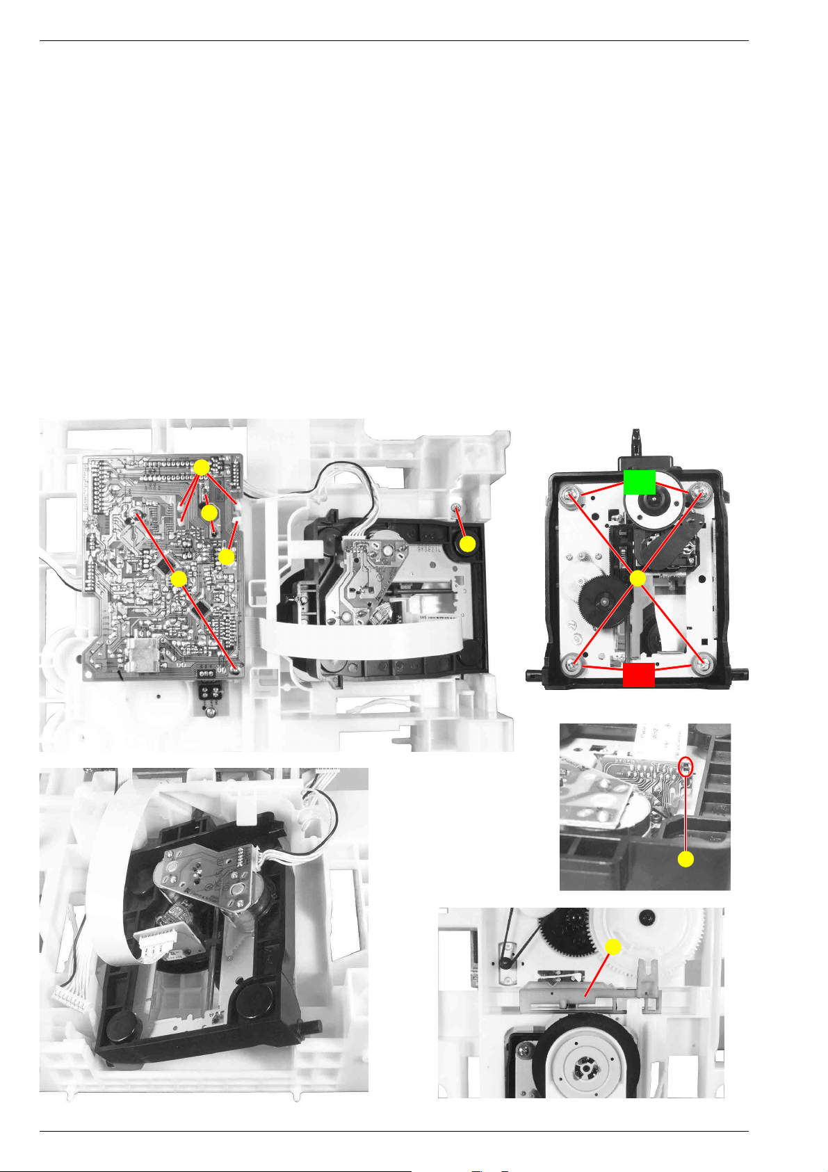
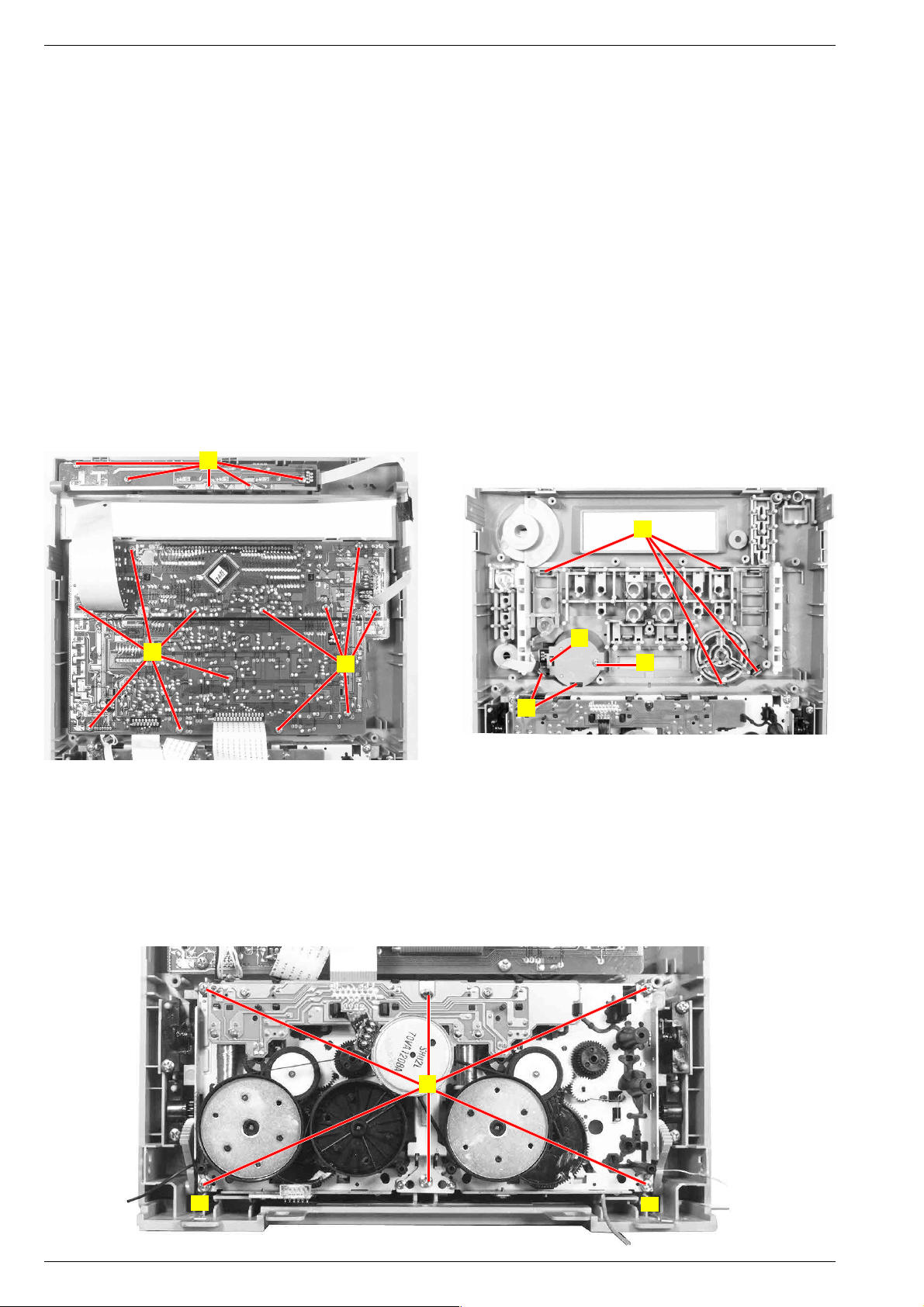
3.3 Schubladenantrieb
- Schublade ausbauen (Punkt 3.2).
- Die Zahnräder können nun abgeschraubt werden.
- Einbau siehe Punkt 3.2 Montage.
3.4 Motor Schubladenantrieb
- CD-Leiterplatte ausbauen (Punkt 3.5).
- Antriebsriemen abnehmen.
- 3 Rastnase N (Fig. 9) ausrasten und Motor herausnehmen.
3.5 CD-Leiterplatte
- 2 Schrauben K (Fig. 9) herausdrehen.
- 2 Motorlötstellen L (Fig. 9) auflöten.
- Rastnase M (Fig. 9) ausrasten und Leiterplatte abnehmen.
- Vor Abziehen des Flexprints Sicherheitslötstelle P (Fig. 11)
schließen.
- Bei Bedarf Steckverbindungen lösen.
3.6 Pickup
- Schraube O (Fig. 9) herausdrehen.
- Schieber I (Fig. 13) in Mittelstellung bringen.
- Pickup mit Montagerahmen herausnehmen (Fig. 12).
- Vor Abziehen des Flexprints Sicherheitslötstelle P (Fig. 11)
schließen.
- 4 Schrauben Q (Fig. 10) herausdrehen.
- Pickup herausnehmen.
- Beim Einbau die Farbe der Gummidämpfer beachten!
3.3 Tray Drive
- Remove the tray (para 3.2).
- The toothed wheels can now be unscrewed.
- Reassembling see para 3.2 Mounting.
3.4 Tray Drive Motor
- Remove the CD PCB (para 3.5).
- Remove the drive belt.
- Disengage 3 hooks N (Fig. 9) and remove the motor.
3.5 CD PCB
- Undo 2 screws K (Fig. 9).
- Unsolder 2 motor solder joints L (Fig. 9).
- Disengage hook M (Fig. 9) and remove the PCB.
- Short circuit the protective solder joint P (Fig. 11) before
unplugging the flexprint connector.
- When necessary unplug connectors.
3.6 Pickup
- Undo screw O (Fig. 9).
- Move slider I (Fig. 13) to mid-position.
- Remove the pickup together with the mounting frame (Fig. 12).
- Short circuit the protective solder joint P (Fig. 11) before
unplugging the flexprint connector.
- Undo 4 screws Q (Fig. 10).
- Remove the pickup.
- When reassembling pay attention to the different colors of the
damper!
Fig. 9
K
N
grün
green
L
O
M
Q
rot
red
Fig. 10
P
Fig. 11
I
Fig. 12 Fig. 13
1 - 6 GRUNDIG Service
Page 7
MS 4101 Allgemeiner Teil / General Section
3.7 Drehteller-Antrieb
- Schublade ausbauen (Punkt 3.2)
- Schraube R (Fig. 14) herausdrehen.
- Der Antrieb ist nun zugänglich.
4. Tunerplatte
- CD-Laufwerk ausbauen (Punkt 3).
- Schraube S (Fig. 15) herausdrehen.
- 2 Schrauben T (Fig. 1) herausdrehen.
- Bei Bedarf Steckverbindungen lösen.
5. Verstärkerplatte
- CD-Laufwerk ausbauen (Punkt 3).
- Schraube S (Fig. 15) herausdrehen.
Achtung: Masseverbindungen f.
- 6 Schrauben U (Fig. 1) herausdrehen.
- Kühlblechabdeckung ausrasten V (Fig. 15) und abnehmen.
- Kühlblechhalter W (Fig. 15) aushängen.
- Schraube X (Fig. 15) herausdrehen.
- Bei Bedarf Steckverbindungen lösen.
6. Standby-Netzteil
- Verstärkerplatte ausbauen (Punkt 5).
- 2 Schrauben Y (Fig. 1) herausdrehen.
- Bei Bedarf Steckverbindungen lösen.
7. Trafo(-platte)
- Verstärkerplatte ausbauen (Punkt 5).
- 4 Schrauben am Trafo herausschrauben.
- Bei Bedarf Steckverbindungen lösen.
8. Frontblende
- CD-Laufwerk ausbauen (Punkt 3).
- 4 Schrauben Z (Fig. 16, 17, 18) herausdrehen.
- 4 Rastungen A (Fig. 16, 17, 18) ausrasten.
- 2 Schrauben D (Masseverbindungen f, Fig. 17) herausdrehen.
- Bei Bedarf Steckverbindungen lösen.
3.7 Turntable Drive
- Remove the tray (para 3.2)
- Undo screw R (Fig. 14).
- Now the turntable drive is accessible.
4. Tuner PCB
- Remove the CD mechanism (para 3).
- Undo screw S (Fig. 15).
- Undo 2 screws T (Fig. 1).
- When necessary unplug connectors.
5. Amplifier PCB
- Remove the CD mechanism (para 3).
- Undo screw S (Fig. 15).
Attention: Ground connections f.
- Undo 6 screws U (Fig. 1).
- Disengage the heat sink cover V (Fig. 15) and remove.
- Unhook heat sink holder W (Fig. 15).
- Undo screw X (Fig. 15).
- When necessary unplug connectors.
6. Standby Power Supply
- Remove the amplifier PCB (para 5).
- Undo 2 screws Y (Fig. 1).
- When necessary unplug connectors.
7. Transformer (PCB)
- Remove the amplifier PCB (para 5).
- Undo the 4 screws of the transformer.
- When necessary unplug connectors.
8. Front
- Remove the CD mechanism (para 3).
- Undo 4 screws Z (Fig. 16, 17, 18).
- Disengage 4 hooks A (Fig. 16, 17, 18).
- Undo 2 screws D (Ground connections f, Fig. 17).
- When necessary unplug connectors.
R
Fig. 14 Fig. 15
f
Z
f
X
W
S
V
B
D
A
f
A
Z
Fig. 16 Fig. 17 Fig. 18
GRUNDIG Service 1 - 7
A
Z
Page 8
Allgemeiner Teil / General Section MS 4101
9. Hauptplatte
- Frontblende lösen (Punkt 8).
- Schraube B (Fig. 16) herausdrehen.
- Schraube C (Fig. 1) herausdrehen.
- Bei Bedarf Steckverbindungen lösen.
10. Obere Bedienplatte
- 5 Schrauben E (Fig. 19) herausdrehen.
- Bei Bedarf Steckverbindung lösen.
11. Untere Bedienplatte
- CD-Laufwerk ausbauen (Punkt 3).
- 12 Schrauben F (Fig. 19) herausdrehen.
- Volume-Knopf abziehen.
- Bei Bedarf Steckverbindungen lösen.
- Bedienplatte vorsichtig abnehmen - Achtung: Flexprint zum Multi
Jog abziehen.
12. Multi Jog
- Untere Bedienplatte ausbauen (Punkt 11).
- 6 Rastungen G (Fig. 20) ausrasten.
- Zierblende abnehmen.
- Schraube H (Fig. 20) herausdrehen.
- Rastung I (Fig. 20) ausrasten.
- Multi Jog herausnehmen.
E
9. Main PCB
- Loosen the front (para 8).
- Undo screw B (Fig. 16).
- Undo screw C (Fig. 1).
- When necessary unplug connectors.
10. Upper Operating PCB
- Undo 5 screws E (Fig. 19).
- When necessary unplug connectors.
11. Lower Operating PCB
- Remove the CD mechanism (para 3).
- Undo 12 screws F (Fig. 19).
- Pull off the volume knob.
- When necessary unplug connectors.
- Carefully remove the operating PCB - Attention: Unplug the
flexprint of the multi jog.
12. Multi Jog
- Remove the lower operating PCB (para 11).
- Disengage 6 hooks G (Fig. 20).
- Remove the decorative cover.
- Undo screw H (Fig. 20).
- Disengage hook I (Fig. 20).
- Remove the multi jog.
F
Fig. 19 Fig. 20
13. Cassetten-Laufwerke
- CD-Laufwerk ausbauen (Punkt 3).
- 6 Schrauben K (Fig. 21) herausdrehen.
Achtung: Masseverbindungen f.
- Bei Bedarf Steckverbindungen lösen.
F
13. Cassette Mechanisms
- Remove the CD mechanism (para 3).
- Undo 6 screws K (Fig. 21).
- When necessary unplug connectors.
G
I
H
G
Attention: Ground connections f.
K
f
Fig. 21
1 - 8 GRUNDIG Service
f
Page 9
MS 4101 Allgemeiner Teil / General Section
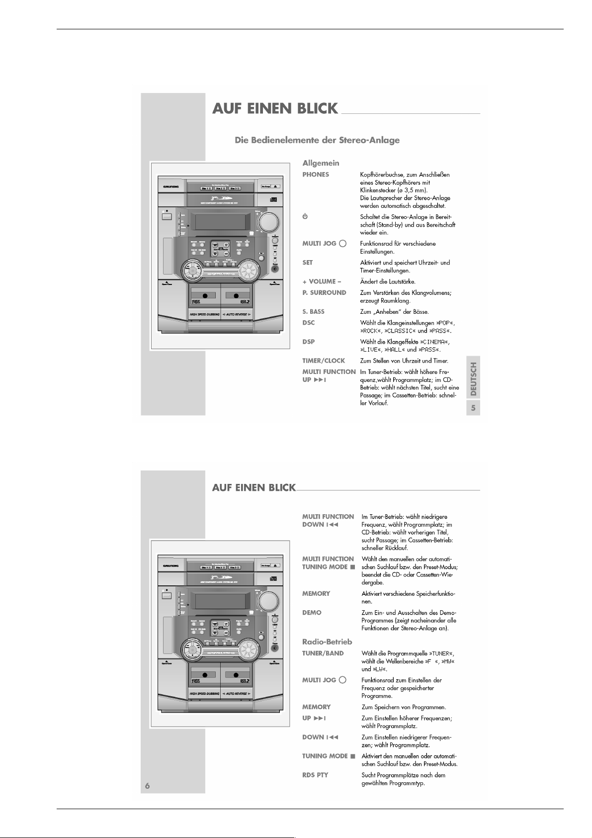
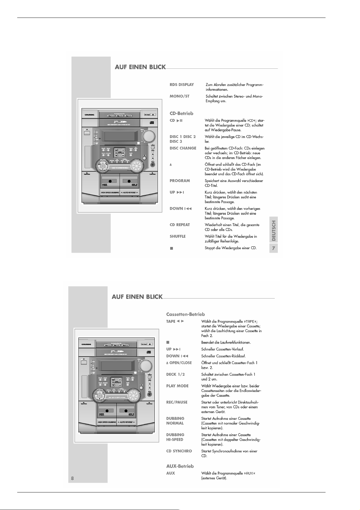
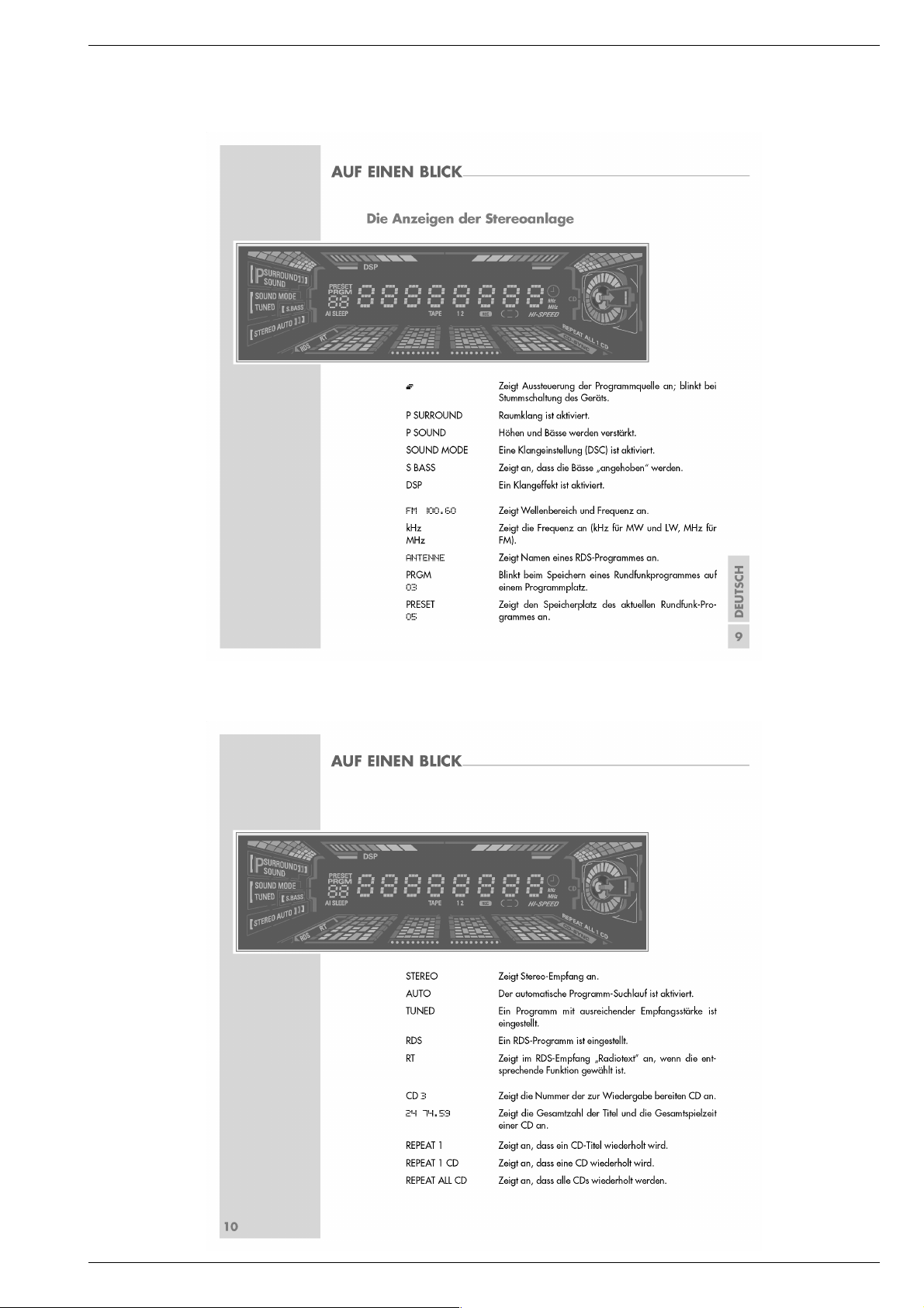
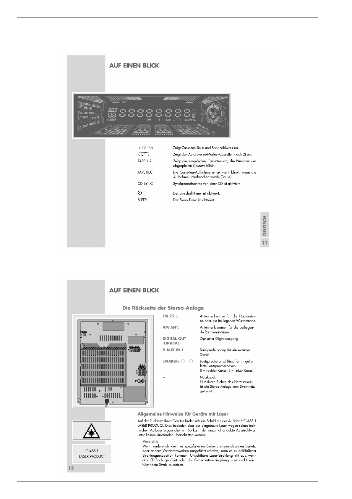
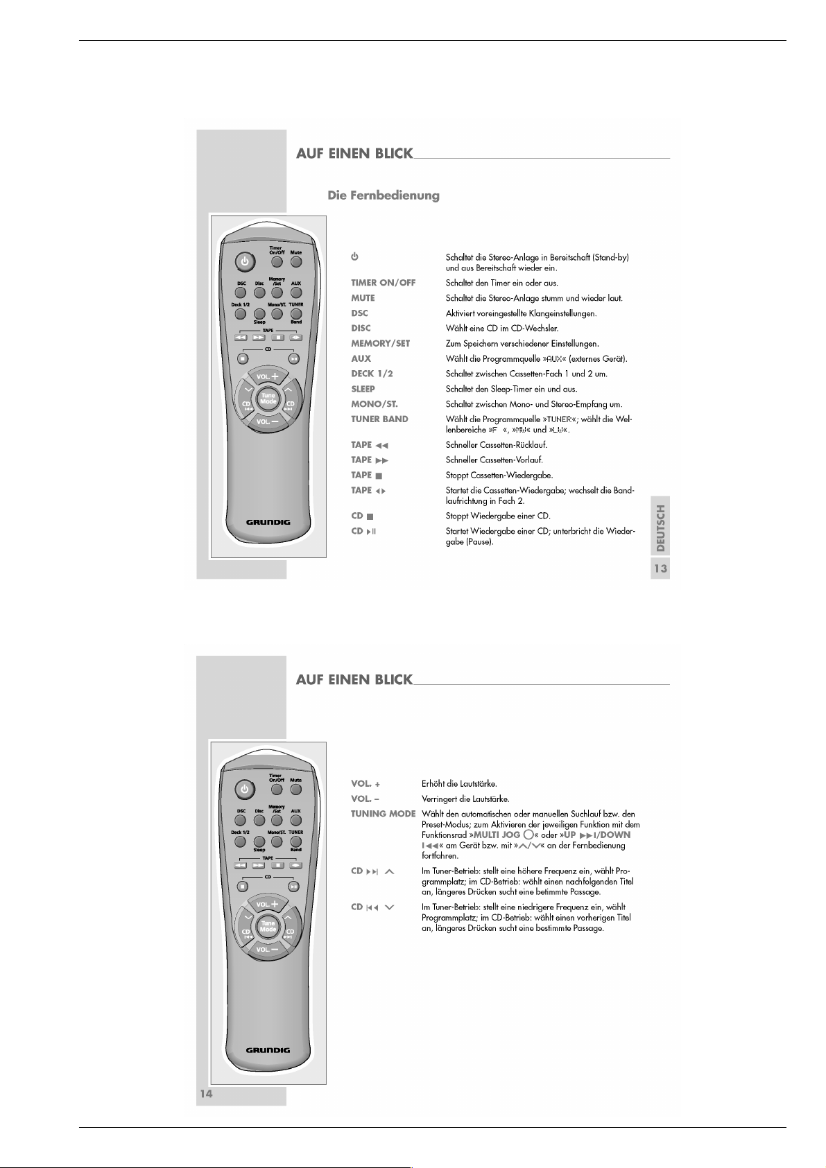
Bedienhinweise
Dieses Kapitel enthält Auszüge aus der Bedienungsanleitung. Weitergehende Informationen entnehmen Sie bitte der gerätespezifischen
Bedienungsanleitung, deren Materialnummer Sie in der entsprechenden Ersatzteilliste finden.
GRUNDIG Service 1 - 9
Page 10
Allgemeiner Teil / General Section MS 4101
1 - 10 GRUNDIG Service
Page 11
MS 4101 Allgemeiner Teil / General Section
GRUNDIG Service 1 - 11
Page 12
Allgemeiner Teil / General Section MS 4101
1 - 12 GRUNDIG Service
Page 13
MS 4101 Allgemeiner Teil / General Section
GRUNDIG Service 1 - 13
Page 14

Allgemeiner Teil / General Section MS 4101
Operating Hints
This chapter contains excerpts from the operating instructions. For further particulars please refer to the appropriate user instructions the part number
of which is indicated in the relevant spare parts list.
1 - 14 GRUNDIG Service
Page 15

MS 4101 Allgemeiner Teil / General Section
GRUNDIG Service 1 - 15
Page 16

Allgemeiner Teil / General Section MS 4101
1 - 16 GRUNDIG Service
Page 17

MS 4101 Allgemeiner Teil / General Section
GRUNDIG Service 1 - 17
Page 18

Allgemeiner Teil / General Section MS 4101
1 - 18 GRUNDIG Service
Page 19

MS 4101 Abgleichvorschriften / Adjustment Procedures
Abgleichvorschriften
Tuner
Messgeräte: Wobbel- / Mess-Sender, Oszilloskop, Digital-Voltmeter
Hinweis: Das Frontend ist ein komplett abgeglichener Baustein. Nur das ZF-Filter muss dem ZF-Verstärker angeglichen werden (Punkt 7).
Abgleich Vorbereitung Abgleichvorgang
1. MW-Oszillator
2. LW-Oszillator
3. AM-ZF
4. MW-Vorkreis
5. LW-Vorkreis
6. FM-Demodulator
7. FM-ZF
MW, 522kHz;
Digital-Voltmeter an Messpunkt A (JW9).
LW, 144kHz;
Digital-Voltmeter an Messpunkt A (JW9).
AM;
Mess-Sender 450kHz in AM-Antennen-Eingang ein-
speisen;
Ue = 50dBµV; f
Oszilloskop an Lautsprecher-Ausgang.
= 1kHz;
mod
MW;
Mess-Sender über Loop-Antennen ankoppeln;
Ue > 50dBµV; f
Oszilloskop an Lautsprecher-Ausgang.
= 1kHz;
mod
LW;
Mess-Sender über Loop-Antennen ankoppeln;
Ue > 50dBµV; f
Oszilloskop an Lautsprecher-Ausgang.
= 1kHz;
mod
FM;
Mess-Sender mit exakter Frequenz an FM-AntennenEingang (alternativ: Rundfunksender).
Digital-Voltmeter zwischen Messpunkte B (IC01-(23))
und C (IC01-(28)).
FM; 98MHz
Wobbel-Mess-Sender an FM-Antennen-Eingang;
Ue = 50dBµV;
Mit MO a auf 1,2V ± 0,1V abgleichen.
Kontrolle bei 1611kHz auf < 7V.
Mit LO b auf 2,0V ± 0,1V abgleichen.
Kontrolle bei 290kHz auf < 7V.
Mit AM IF c auf NF-Maximum abgleichen.
Mit MA d bei 594kHz auf NF-Maximum abgleichen.
Mit LA e bei 150kHz auf NF-Maximum abgleichen.
Mit FM-DET f auf 0V ± 0,05V abgleichen.
Mit g auf Maximum und Symmetrie einstellen.
8. FM-Suchlaufstopp
9. 19kHz-Sperrkreise
FM; 98MHz
Mess-Sender an FM-Antennen-Eingang;
Ue = 28dBµV;
FM;
Mess-Sender an FM-Antennen-Eingang;
Ue = 50dBµV; f
Oszilloskop an Lautsprecher-Ausgänge.
= 19kHz;
mod
SVR1 h so abgleichen, dass "TUNED" im Display gerade beginnt aufzuleuchten.
Mit B.P.F i (linker Kanal) und mit B.P.F j (rechter
Kanal) auf NF-Minimum abgleichen.
GRUNDIG Service 2 - 1
Page 20

Abgleichvorschriften / Adjustment Procedures MS 4101
Cassette
Messgeräte: Frequenzzähler, Oszilloskop, Test-Cassette 3150Hz/10kHz (z.B. 448)
Abgleich Vorbereitung Abgleichvorgang
1. Lösch-Oszillator
2. Vormagnetisierung
3. Wiedergabe-Pegel
4. Azimut Deck 1
5. Azimut Deck 2
Frequenzzähler an Messpunkt A (JCW1-(5)).
Leer-Cassette einlegen und Aufnahme starten.
Leer-Cassette in Deck 2 einlegen und Aufnahme starten.
Linker Kanal: Oszilloskop an Messpunkt B (JCW1-(1),
Masse: JCW1-(6)).
Rechter Kanal: Oszilloskop an Messpunkt C (JCW1-(4),
Masse: JCW1-(6)).
Test-Cassette in Deck 1 einlegen und 3150Hz-Teil abspielen.
Oszilloskop an Lautsprecher-Ausgänge.
Oszilloskop an Lautsprecher-Ausgang.
Test-Cassette in Deck 1einlegen und 10kHz-Teil abspielen.
Oszilloskop an Lautsprecher-Ausgang.
Test-Cassette in Deck 2 einlegen und 10kHz-Teil abspielen.
Mit JL1 a auf 105kHz ± 0,5kHz abgleichen.
Mit JSR2L b auf 0,7V
Mit JSR2R c auf 0,7V
(2,0Vss) ± 0,1V abgleichen.
eff
(2,0Vss) ± 0,1V abgleichen.
eff
Mit JSR1L d im linken Kanal den gleichen Pegel wie im
rechten enstellen.
Mit Kopfschraube e auf maximalen und gleichen
Pegel auf beiden Kanälen abgleichen.
e
Bei Laufrichtung >> mit Kopfschraube f auf maximalen und gleichen Pegel auf beiden Kanälen abgleichen.
Bei Laufrichtung << mit Kopfschraube g auf maximalen und gleichen Pegel auf beiden Kanälen abgleichen.
fg
6. BandGeschwindigkeit
Frequenzzähler an Lautsprecher-Ausgang.
Test-Cassette einlegen und 3150Hz-Teil abspielen.
Mit dem Einstellregler VSR1 (untere Bedienplatte)
auf 3150Hz ± 0,1% einstellen.
2 - 2 GRUNDIG Service
Page 21

MS 4101 Abgleichvorschriften / Adjustment Procedures
Adjustment Procedures
Tuner
Test equipment: Sweep / Signal Generator, Oscilloscope, Digital Voltmeter
Note: The frontend is a completely preadjusted module. Only the IF filter must be adjusted to the IF amplifier (para 7).
Adjustment Preparation Adjustment Procedure
1. MW Oscillator
2. LW Oscillator
3. AM IF
4. MW Band Pass
5. LW Band Pass
6. FM Demodulator
7. FM IF
MW, 522kHz
Digital Voltmeter to Testpoint A (JW9).
LW, 144kHz
Digital Voltmeter to Testpoint A (JW9).
AM;
Signal Generator 450kHz to AM Aerial Input;
Ue = 50dBµV; f
Oscilloscope to Loudspeaker Output.
= 1kHz;
mod
AM;
Couple Signal Generator via Loop Antennas;
Ue > 50dBµV; f
Oscilloscope to Loudspeaker Output.
= 1kHz;
mod
AM;
Couple Signal Generator via Loop Antennas;
Ue > 50dBµV; f
Oscilloscope to Loudspeaker Output.
= 1kHz;
mod
FM;
Signal Generator with exact frequency to FM Aerial Input
(alternatively: Radio Station).
Digital Voltmeter between Testpoints B (IC01-(23))
and C (IC01-(28)).
FM, 98MHz;
Sweep Generator to FM Aerial Input;
Ue = 50dBµV;
Adjust with MO a for 1.2V ± 0.1V.
Check at 1611kHz for < 7V.
Adjust with LO b for 2.0V ± 0.1V.
Check at 290kHz for < 7V.
Adjust with AM IF c for AF Maximum.
Adjust with MA d at 594kHz for AF Maximum.
Adjust with LA e at 150kHz for AF Maximum.
Adjust with FM-DET f for 0V ± 0.05V.
Adjust g to maximum and symmetry.
8. FM Search Stop
9. 19kHz Filter
FM, 98MHz;
Signal Generator to FM Aerial Input;
Ue = 28dBµV;
FM;
Signal Generator to FM Aerial Input;
Ue = 50dBµV; f
Oscilloscope to Loudspreaker Outputs.
= 19kHz;
mod
Adjust SVR1 h so that "TUNED" in the display just
appears.
Adjust with B.P.F i (left channel) and with B.P.F j
(right channel) for AF Minimum.
GRUNDIG Service 2 - 3
Page 22

Abgleichvorschriften / Adjustment Procedures MS 4101
Cassette
Test equipment: Frequency Counter, Oscilloscope, Test Cassette 3150Hz/10kHz (z.B. 448)
Adjustment Preparation Adjustment Procedure
1.Bias Oscillator
2. Bias Voltage
3. Playback Level
4. Azimuth Deck 1
5. Azimuth Deck 2
Frequency Counter to Testpoint A (JCW1-(5)).
Insert empty Cassette and start recording.
Insert empty Cassette in Deck 2 and start recording.
Left Channel: Oszilloscope to Testpoint B (JCW1-(1),
GND: JCW1-(6)).
Right Channel: Oszilloscope to Testpoint B (JCW1-(4),
GND: JCW1-(6)).
Insert Test Cassette in Deck 1 and play 3150Hz part.
Oscilloscope to Loudspreaker Outputs.
Oscilloscope to Loudspreaker Outputs.
Insert Test Cassette in Deck 1 and play 10kHz part.
Oscilloscope to Loudspreaker Outputs.
Insert Test Cassette in Deck 2 and play 10kHz part.
Adjust JL1 a for 105kHz ± 0.5kHz.
Adjust JSR2L b for 0.7V
Adjust JSR2R c for 0.7V
(2.0Vpp) ± 0.1V.
rms
(2.0Vpp) ± 0.1V.
rms
With JSR1L d adjust on the left channel the same level
as on the right channel.
With Head Screw e adjust for maximal and equal level
on both channels.
e
At Tape Direction >> adjust with Head Screw f for
maximal and equal level on both channels.
At Tape Direction << adjust with Head Screw g for
maximal and equal level on both channels.
fg
6. Tape Speed
Frequency Counter to Loudspreaker Output.
Insert Test Cassette and play 3150Hz part.
Adjust VSR1 (lower Front) for 3150Hz ± 0.1%.
2 - 4 GRUNDIG Service
Page 23

MS 4101 Schaltpläne und Platinenabbildungen / Circuit Diagrams and Layout of the PCBs MS 4101 Schaltpläne und Platinenabbildungen / Circuit Diagrams and Layout of the PCBs
Schaltpläne und Platinenabbildungen / Circuit Diagrams and Layout of the PCBs
Haupt-Platte (Teil 1) / Main Board (Part 1)
to CW106
S./p. 3-16
L
Spannungen
Voltages FIC4
Pin
10V
20V
30V
4 -12V
50V
60V
70V
8 12V
to ACW1-1
S./p. 3-7
T
to FCW1-1
S./p. 3-11
C
to CON01
S./p. 3-19
Q
Spannungen / Voltages FIC1
Pin
1 4V3
2 4V3
3 4V3
4 4V3
5 4V3
6 4V3
7 4V3
8 4V3
9 4V3
10 4V3
11 4V3
12 4V3
13 4V3
14 4V3
Pin
15 4V3
16 4V3
17 4V3
18 4V3
19 4V3
20 0V
21 4V8
22 4V8
23 4V3
24 8V6
25 0V
26 3V7
27 3V7
28 4V3
Spannungen
Voltages FIC2
Pin
10V
20V
30V
4 -12V
50V
60V
70V
8 12V
to ACW10-1
S./p. 3-8
V
A
B
GRUNDIG Service GRUNDIG Service3 - 1 3 - 2
Page 24

Schaltpläne und Platinenabbildungen / Circuit Diagrams and Layout of the PCBs MS 4101 Schaltpläne und Platinenabbildungen / Circuit Diagrams and Layout of the PCBs MS 4101
Haupt-Platte (Teil 2) / Main Board (Part 2)
A
B
Spannungen / Voltages JIC1
S
Pin
1 2V7
2 1V3
30V
40V
50V
60V
70V
8 2V0
90V
10 0V
11 0V
12 0V
Pin
13 0V
14 0V
15 0V
16 0V6
17 8V4
18 0V
19 0V
20 0V
21 0V
22 0V
23 1V3
24 2V6
d
-12V
-23V
to ACW2-1
S./p. 3-7
U
to LCW10
S./p. 3-23
N
+24V
+24V
-24V
R
CB
A
c
a
b
-35V
+55V
-55V
-27V
36V~
80V~
to RCW1-1
S./p. 3-23
M
3 - 3 3 - 4
GRUNDIG Service GRUNDIG Service
Page 25

MS 4101 Schaltpläne und Platinenabbildungen / Circuit Diagrams and Layout of the PCBs MS 4101 Schaltpläne und Platinenabbildungen / Circuit Diagrams and Layout of the PCBs
Sicht auf Bestückungsseite / View on Component Side
GRUNDIG Service GRUNDIG Service3 - 5 3 - 6
Page 26

Schaltpläne und Platinenabbildungen / Circuit Diagrams and Layout of the PCBs MS 4101 Schaltpläne und Platinenabbildungen / Circuit Diagrams and Layout of the PCBs MS 4101
NF-Verstärker / AF Amplifier
Spannungen / Voltages AIC1
to ACW1
S./p. 3-2
T
Pin
1 55V
2 24V
3 10V
4 -10V
5 -24V
6 -55V
70V
80V
90V
Pin
10 0V
11 0V
12 -54V
13 +54V
14 0V
15 0V
16 0V
17 0V
18 0V
to HCW1-1
S./p. 3-11
F
Spannungen
Voltages AIC2
Pin
1 12V
2 22V
3 5V7
4
5 4V5
60V
7 4V5
8 407
9 8V8
10 22V
11 12V
to ACW10
S./p. 3-2
V
to ACW2
S./p. 3-4
U
3 - 7 3 - 8
GRUNDIG Service GRUNDIG Service
Page 27

MS 4101 Schaltpläne und Platinenabbildungen / Circuit Diagrams and Layout of the PCBs MS 4101 Schaltpläne und Platinenabbildungen / Circuit Diagrams and Layout of the PCBs
Sicht auf Bestückungsseite / View on Component Side
GRUNDIG Service GRUNDIG Service3 - 9 3 - 10
Page 28

Schaltpläne und Platinenabbildungen / Circuit Diagrams and Layout of the PCBs MS 4101 Schaltpläne und Platinenabbildungen / Circuit Diagrams and Layout of the PCBs MS 4101
Keys1
Keys2
Keys3
Tastenspannungen / Key Voltages
Keys1 4V95
USW1
(Disc1)
2V35
USW2
(Disc2)
2V79
USW3
(Disc3)
3V21
USW4
(Change)
3V60
USW5
(/)
4V04
USW7
(ON)
1V55
USW8
(Demo)
1V15
USW9
(PTY)
0V77
USW10
(Display)
0V38
USW11
(Timer)
0V0
Tastenspannungen / Key Voltages
Keys2 4V95
USW13
(Tuning)
4V04
USW14 (
Down ∞)
3V60
USW15
(Up §)
3V21
USW16
(Rec/Pause)
2V79
USW17
(CD Synchro)
2V35
USW18
(TAPE)
1V91
USW19
(TUNER)
1V55
USW20
(Rev.Mode)
1V15
USW21
(Memory)
0V77
USW22
(Deck1/2)
0V38
USW23
(Mono/St)
0V0
Tastenspannungen / Key Voltages
Keys2 4V95
USW24
(Surround)
4V48
USW25
(Bass)
4V04
USW26
(DSC)
3V60
USW27
(DSP)
3V21
USW28
(SET)
2V79
USW29
(CD Repeat)
2V35
USW30
(Program)
1V91
USW31
(Shuffle)
1V55
USW32
(Hi-Speed)
1V15
USW33
(Normal)
0V77
USW34
(AUX)
0V38
USW35
(CD)
0V0
Front-Platte / Front Board
to FCW1
S./p. 3-1
C
to CW105
S./p. 3-16
D
A
B
E
to HCW1
S./p. 3-8
F
3 - 11 3 - 12
GRUNDIG Service GRUNDIG Service
Page 29

MS 4101 Schaltpläne und Platinenabbildungen / Circuit Diagrams and Layout of the PCBs MS 4101 Schaltpläne und Platinenabbildungen / Circuit Diagrams and Layout of the PCBs
Sicht auf Bestückungsseite / View on Component Side
GRUNDIG Service GRUNDIG Service3 - 13 3 - 14
Page 30

Schaltpläne und Platinenabbildungen / Circuit Diagrams and Layout of the PCBs MS 4101 Schaltpläne und Platinenabbildungen / Circuit Diagrams and Layout of the PCBs MS 4101
CD-Platte / CD Board
I
J
to CCW1
S./p. 3-1
L
to OCW1
S./p. 3-23
G
K
CD-Mechanik
CD Mechanism
3 - 15 3 - 16
GRUNDIG Service GRUNDIG Service
H
CD-Mechanik
CD Mechanism
to FCW2
S./p. 3-12
D
Page 31

MS 4101 Schaltpläne und Platinenabbildungen / Circuit Diagrams and Layout of the PCBs MS 4101 Schaltpläne und Platinenabbildungen / Circuit Diagrams and Layout of the PCBs
Sicht auf Lötseite / View on Solder SideSicht auf Bestückungsseite / View on Component Side
GRUNDIG Service GRUNDIG Service3 - 17 3 - 18
Page 32

Schaltpläne und Platinenabbildungen / Circuit Diagrams and Layout of the PCBs MS 4101 Schaltpläne und Platinenabbildungen / Circuit Diagrams and Layout of the PCBs MS 4101
Tuner
Spannungen / Voltages IC01
A
d
g
a
h
Pin
1 3V6
2 8V9
3 3V5
4 3V6
50V
6 5V2
7 5V3
8 8V8
9 8V7
10 1V3
11 0V3
12 0V
13 0V
14 7V8
15 7V8
C
Pin
16 4V3
17 4V3
18 4V3
19 4V3
20 3V3
21 3V3
22 2V9
23 3V4
24 0V
25 0V
26 3V8
27 3V8
28 3V7
29 3V7
30 2V0
B
ij
Spannungen / Voltages IC02
Pin
1 2V2
20V
30V
4 4V8
5 5V1
6 0V1
7 7V8
8 7V8
90V
10 0V
Pin
11 0V
12 0V
13 0V
14 2V5
15 5V2
16 0V9
17 0V9
18 0V
19 0V
20 2V0
e
b
c
f
Spannungen / Voltages IC02
Pin
1 1V9
20V
3 2V1
4 2V1
5 3V9
60V
70V
8 2V1
Pin
90V
10 0V
11 4V7
12 3V9
13 1V9
14 1V9
15 3V9
16 1V9
to TCW1 S./p. 3-1 Q
3 - 19 3 - 20
GRUNDIG Service GRUNDIG Service
Page 33

MS 4101 Schaltpläne und Platinenabbildungen / Circuit Diagrams and Layout of the PCBs MS 4101 Schaltpläne und Platinenabbildungen / Circuit Diagrams and Layout of the PCBs
Sicht auf Lötseite / View on Solder SideSicht auf Bestückungsseite / View on Component Side
GRUNDIG Service GRUNDIG Service3 - 21 3 - 22
Page 34

Schaltpläne und Platinenabbildungen / Circuit Diagrams and Layout of the PCBs MS 4101 Schaltpläne und Platinenabbildungen / Circuit Diagrams and Layout of the PCBs MS 4101
to RCW3
S./p. 3-4
N
Standby-Netzteil / Standby Power Supply
Sicherungs-Platte
Fuse Board
18V~
18V~40V~
Netzteil-Platte
Power Supply Board
O
P
Netz / Mains
230V~ 50/60Hz
Standby-Netzteil
Standby Power Supply
to RCW1
S./p. 3-4
40V~
M
35V~
5V~
Optischer Ausgang / Optical Output
to CW107
S./p. 3-16
G
O
Sicherungs-Platte
Fuse Board
Netzteil-Platte
Power Supply Board
3 - 23 3 - 24
GRUNDIG Service GRUNDIG Service
Page 35

MS 4101 Schaltpläne und Platinenabbildungen / Circuit Diagrams and Layout of the PCBs MS 4101 Schaltpläne und Platinenabbildungen / Circuit Diagrams and Layout of the PCBs
Verdrahtungsplan / Wiring Diagram
Tuner
CON01
Q
Jog-Platte
Jog Board
FCW4-1
A
B
FCW3-1
CD-Tasten-Platte
CD Key Board
FCW1
C
TCW1
FCW3
B
CD-Mechanik
CD Mechanism
Pick-Up
Front-Platte
Front Board
C
FCW1-1
Optischer Ausgang
Optical Output
OCW1
G
FCW2
D
FCW4
A
DCW1
HCW1-1
EF
RCW2
O
JCW1
R
RCW3
N
JCW2
S
Haupt-Platte
Main Board
M
RCW1
ACW1
T
CCW1
L
ACW2
U
ACW10-1
V
H
IJ
CW101
CW104
CW102
CW103
K
CD-Platte
CD Board
D
CW105
CW107
CW106
L
G
CASS
DECK 1
CASS
DECK 2
M
RCW1-1
Sicherungs-Platte
Fuse Board
Netzteil-Platte
Power Supply
OP
LCW11 LCW12
Standby Netzteil
Standby Power Supply
N
LCW10
Board
ACW10
V
ACW1-1
T
NF-Verstärker
AF Amplifier
U
ACW2-1
F
HCW1
GRUNDIG Service GRUNDIG Service3 - 25 3 - 26
Page 36

Schaltpläne und Platinenabbildungen / Circuit Diagrams and Layout of the PCBs MS 4101 Schaltpläne und Platinenabbildungen / Circuit Diagrams and Layout of the PCBs MS 4101
V
SS3
comparator
8th Switched
capacitor filter
anti-aliasing
filter
120kΩ
100kΩ
100kΩ
Analog
Power supply
Digital
Power supply
PLL
57kH
Z
RDS/ARI
PLL
1187.5Hz
Bi-phase
decoder
Measurement
circuit
Differential
decoder
Reference
clock
(4)
(3)
(5)
(6)
(12)
(11)
(13) (14) (10)
(7) (8)
(16)
(2)
(9)
(1)
2728
+
LEVEL
SHIFT
LEVEL
SHIFT
LEVEL
SHIFT
LEVEL
SHIFT
REGULATOR
BUY
BUY
10K
10K
10K
10K
50K
50K
MUTE
10K
10K
BUY
_
+
_
26 25 24 23 18 17 16 15
21 3 4 5 6 7 8 11 12 13
22 2021 19
9 10 14
+
_
+
_
+
_
+
_
+
_
+
_
+
_
+
T.S D
_
+
_
1 2 3 4 5 6 7 8 9 10 11 12 13 14 15
30 29 28 27 26 25 24 23 22 21 20 19 18 17 16
ALC
BUFF
AM
OSC
AM
MIX
REG
AM
RF.AMP
AGC
DETAM IF
SD
COMP
AM
S-METER
FM
S-METER
S-CURVE
AM/FM
IF-BUFF
AM IF
FM
DET
TUNING
DRIVE
STEREO
DRIVE
GND GND
STEREO
SW
MUTE
VCO
304kHzFF38k
PILOT
DET
FF
19k ∠ –
π
2
FF
19k ∠ Θ
P-DET
ø
DECODER
ANTI-BIRDIE
3rd or 5th
IC-Innenbeschaltungen / IC Block Diagrams
IC301
IC02
LC 72131 M
1
XIN 10
22
XOUT
CCB
I/F
POWER ON
RESET
1/2
FM IN
AM IN
CE
DO
VDO
VSS
16
15
3
4
DI
5
CL
6
17
21
REVERENCE
DIVIDER
SWALLOW COUNTER
1/16, 1/17 4bits
12 bits PROGRAMMABLE
DIVIDER
DATA SHIFT REGISTER
LATCH
PHASE DETECTOR
CHARGE PUMP
UNLOCK
DETECTOR
UNIVERSAL
COUNTER
131110987
IO2IO1BO4BO3BO2BO1
KA 9258 D
PO
19
A IN
20
A OUT
1212
IF IN
IC03
BU 1924
WIC401
WIC402
KA 3082
BIAS
1234
GND
AIC2
V
S
L 4959
3 - 27 3 - 28
EN 12V(a)
EN 12V(b)
EN 8V
O1
V
2/10
8
7
5
V
REF
GEN
Z1
LOGIC SWITCH
V
CTL
DRIVER OUT
PRE DRIVER
678910
5
V
IN1VIN2
5.6V, 250mA
REGULATOR
8.6V, 600mA
REGULATOR
SWITCHED
12V, 800mA
REGULATOR
SWITCHED
12V, 1.3A
REGULATOR
SWITCHED
11
10
9
8
7
6
5
4
3
2
1
SV
CC
OUT 12V(a)
V
S
OUT 8.6V
EN 8.6V
EN 12V(a)
GND
EN 12V(b)
N.C.
OUT 5.6V
V
S
OUT 12V(b)
TSD
PV
CC
V
O2
V
Z2
IC01
3
OUT 5.6V
9
OUT 8.6V
11
OUT 12V(a)
1
OUT 12V(b)
GND
6
GRUNDIG Service GRUNDIG Service
LA 1837
Page 37

MS 4101 Explosionszeichnungen und Ersatzteilliste / Exploded Views and Spare Parts List MS 4101 Explosionszeichnungen und Ersatzteilliste / Exploded Views and Spare Parts List
Explosionszeichnungen und Ersatzteilliste / Exploded Views and Spare Parts List
A
GRUNDIG Service GRUNDIG Service4 - 1 4 - 2
Page 38

Explosionszeichnungen und Ersatzteilliste / Exploded Views and Spare Parts List MS 4101 Explosionszeichnungen und Ersatzteilliste / Exploded Views and Spare Parts List MS 4101
CD-Laufwerk / CD Drive
B
Cassetten-Laufwerk / Tape Drive
C
4 - 3 4 - 4
GRUNDIG Service GRUNDIG Service
Page 39

MS 4101 Explosionszeichnungen und Ersatzteilliste / Exploded Views and Spare Parts List
Lautsprecherboxen / Loudspeaker Boxes
D
GRUNDIG Service 4 - 5
Page 40

4 - 6 GRUNDIG Service
Ersatzteilliste
Spare Parts List
9 / 2001
POS. NR. ABB. MATERIAL-NR. ANZ. BEZEICHNUNG DESCRIPTION
POS. NO. FIG. PART NUMBER QTY.
0001.000 A 759550440100 KNOPF MULTI JOG KNOB MULTI JOG
0002.000 A 759550440200 ABDECKUNG JOG/FUNKTION COVER JOG/FUNCTION
0003.000 A 759550440300 BLENDE FUNKTION MASK FUNCTION
0004.000 A 759550440400 HALTER KNOPF MULTI JOG HOLDER KNOB MULTI JOG
0005.000 A 759550440500 KNOPF LAUTSTAERKE KNOB VOLUME
0006.000 A 759550440600 FENSTER CASS LINKS WINDOW CASS LEFT
0007.000 A 759550440700 FENSTER CASS RECHTS WINDOW CASS RIGHT
0008.000 A 759550440800 TUER CASS LINKS DOOR CASS LEFT
0009.000 A 759550440900 TUER CASS RECHTS DOOR CASS RIGHT
0010.000 A 759550441000 FEDER EJEKT LINKS SPRING EJECT LEFT
0011.000 A 759550441100 FEDER EJEKT RECHTS SPRING EJECT RIGHT
0012.000 A 759550441200 GEHAEUSEVORDERTEIL FRONT CABINET
0013.000 A 759550441300 FENSTER DISPLAY WINDOW DISPLAY
0014.000 A 759550441400 FENSTER TUER CD WINDOW DOOR CD
0015.000 A 759550441500 TUER CD DOOR CD
0016.000 A 759550441600 FENSTER DISC WINDOW DISC
0019.000 A 759550173100 2 BREMSE TUER CASS BRAKE DOOR CASS
0020.000 A 759550173000 2 HALTER BREMSE HOLDER BRAKE
0021.000 A 759550441700 KNOPF BASS/KLANG KNOB BASS/SOUND
0022.000 A 759550441800 KNOPF SURROUND KNOB SURROUND
0023.000 A 759550441900 LINSE SURROUND LENS SURROUND
0024.000 A 759550442000 2 LINSE LINKS/RECHTS LENS LEFT/RIGHT
0025.000 A 759550442100 LINSE DUBBING LENS DUBBING
0026.000 A 759550442200 KNOPF SET KNOB SET
0027.000 A 759550442300 LINSE SET LENS SET
0029.000 A 759550442400 LINSE FUNKTION LENS FUNCTION
0030.000 A 759550442500 FILTER FUNKTION FILTER FUNCTION
0031.000 A 759550442600 KNOPF FUNKTION KNOB FUNCTION
0032.000 A 759550442700 KNOPF DISC KNOB DISC
0033.000 A 759550442800 LINSE DISC LENS DISC
0034.000 A 759550442900 KNOPF MULTI FUNKTION KNOB MULTI FUNCTION
0035.000 A 759550443000 KNOPF POWER KNOB POWER
0037.000 A 759550443100 GRUNDIG LOGO GRUNDIG LOGO
0038.000 A 759550443200 LINSE POWER LENS POWER
0080.000
0090.000 759550449600 TUNER KPL FM/MW/LW/RDS TUNER KPL FM/MW/LW/RDS
0094.000 759550159900 TUER BATTERIE RC DOOR BATTERY RC
0095.000 759550449800 FERNBEDIENUNG REMOTE CONTROL
0001.000 B 759550174200 SCHIEBER SLIDER
0002.000 B 759550174300 RIEMEN LADEN BELT LOAD
0003.000 B 759550174400 HUBRAD PULLY GEAR PULLEY
0004.000 B 759550174500 HUBRAD LADEN GEAR LOAD
0005.000 B 759550174600 KURVENRAD GEAR CAM
0006.000 B 759550174700 HUBRAD SCHUBLADE GEAR TRAY
0007.000 B 759550174800 HUBRAD KONVERTER GEAR CONVERT
0008.000 B 759550174900 HUBRAD SYNCHRON GEAR SYNCRO
0009.000 B 759550443300 GETRIEBE MOTOR GEAR MOTOR
0010.000 B 759550443400 MOTOR LADEN MOTOR LOADING
0011.000 B 759550443500 GETRIEBE DREHTELLER GEAR ROTARY PLATE
0012.000 B 759550443600 DREHTELLER ROTARY PLATE
ǵ
AUDIO/HIFI
MS 4101
MATERIAL-NR. / PART NO.: 755098105000
BESTELL-NR. / ORDER NO.: GLM0150 CHROM
d©
755098105000 MS 4101 CHROM MS 4101 CHROM
S 759550449500 NETZKABEL250V2,5A1540MM POWER CABLE 250V2,5A1540M
KEIN E-TEIL NO SPARE PART
LAUFWERK CD DRIVE MECHANISM CD
POS. NR. ABB. MATERIAL-NR. ANZ. BEZEICHNUNG DESCRIPTION
POS. NO. FIG. PART NUMBER QTY.
0013.000 B 759550443700 SCHUBLADE CD DRAWER CD
0014.000 B 759550443800 SENSOR SENSOR
0016.000 B 759550443900 MAGNET MAGNET
0017.000 B 759550444000 ANDRUCKSCHEIBE CD CHUCKING PLATE CD
0018.000 B 759550444100 FILZSCHEIBE FELT DISC
0019.000 B 759550444200 MICRO SCALTER SWITCH MICRO
0020.000 B 759550444300 MOTOR DC MOTOR DC
0021.000 B 759550444400 PULLY MOTOR PULLEY MOTOR
0022.000 B 759550444500 PUFFER ROT CUSHION RED
0023.000 B 759550444600 LAUFWER CD CMS-D73SG6U MECHANISM CD CCMS-D73SG6U
0026.000 B 759550175400 PUFFER GRUEN CUSHION GREEN
759550159000 LAUFWERK CASS ADR246ANW DRIVE MECHANISM ADR246AMW
0001.000 C 759550159100 KOMBI KOPF ADR2400-RP COMBINATION HEAD ADR2400-
0002.000 C 759550159200 KOPF WIEDERGABE TC881CB HEAD PLAY TC881CB
0003.000 C 759550159300 MOTOR KPL ADR2400SHU2L MOTOR CPL ADR2400SHU2L
0004.000 C 759550159400 HAUPTRIEMEN 1 0,5 BELT MAIN 1 0,5
0005.000 C 759550159500 HAUPTRIEMEN 2 1,3 BELT MAIN 2 1,3
0006.000 C 759550159600 RIEMEN UNTEN BELT SUB
0007.000 C 759550159700 TAUCHANKERMAGNET SOLENOID
0001.000 D 759550446800 2 GEHAEUSEVORDERTEIL BOX FRONT CABINET BOX
0002.000 D 759550446900 2 RAHMEN BESPANNUNG KPL FRAME COVERRING CPL
0003.000 D 759550447000 2 LAUTSPRECHER TIEFTON LOUDSPEAKER WOOFER
0004.000 D 759550447100 2 LAUTSPRECHER HOCHTON LOUDSPEAKER TWEETER
720114011000 BEDIENUNGSANLEITUNG D/GB OPERATING INSTRUCTION D/G
720114011100 BEDIENUNGSANLEITUNG F/I OPERATING INSTRUCTION F/I
720107717000 SERVICE MANUAL D/GB SERVICE MANUAL D/GB
POS. NR. MATERIAL-NR. BEZEICHNUNG
POS. NO. PART NUMBER DESCRIPTION
AC 00054 759550448700 ELKO 3300UF25V20%
AD 00001 830921504500 DIODE 1N4148 AV619 -GA
AD 00002 830921504500 DIODE 1N4148 AV619 -GA
AD 00003 830921504500 DIODE 1N4148 AV619 -GA
AD 00004 830921504500 DIODE 1N4148 AV619 -GA
AD 00005 830921504500 DIODE 1N4148 AV619 -GA
AD 00051 759540286400 DIODE 1N4002GPF
AD 00052 759540286400 DIODE 1N4002GPF
AD 00053 759540286400 DIODE 1N4002GPF
AD 00054 759540286400 DIODE 1N4002GPF
AD 00057 830921504500 DIODE 1N4148 AV619 -GA
AD 00058 759540286400 DIODE 1N4002GPF
AIC 00001 759550445400 IC STK412000
AIC 00002 759550445500 IC L4959
AQ 0002L 759854350000 TRANS.KSD 471 Y 214940112
AQ 0002R 759854350000 TRANS.KSD 471 Y 214940112
AQ 0003L 759550445200 TRANS:KSC1009YTA
AQ 0003R 759550445200 TRANS:KSC1009YTA
AQ 00004 759853700000 TRANS.KSA 733 C 33-C 2139
AQ 00005 759510451400 TRANS.KSC 945 Y
AQ 00006 759510451400 TRANS.KSC 945 Y
AQ 00007 759510451900 TRANS.KSR 2003
AQ 00008 759853980000 TRANS.KSC 1008 Y 21493014
AQ 00009 759853700000 TRANS.KSA 733 C 33-C 2139
AQ 00051 759550448600 IC KA7805AB
AQ 00052 759853980000 TRANS.KSC 1008 Y 21493014
AR 0009L 759550445600 R-METALL PLATTE 0,22OHM7W
AR 0009R 759550445600 R-METALL PLATTE 0,22OHM7W
d©
BOX LS SPEAKER BOX
POS. NR. MATERIAL-NR. BEZEICHNUNG
POS. NO. PART NUMBER DESCRIPTION
AR00010
S 870522704900 MOW 0411 100 OHM 5% AV619
AR00011 S 870522704900 MOW 0411 100 OHM 5% AV619
AR0012L
S 870522701700 MOW 0411 4,7 OHM 5% DRA
AR0012R S 870522701700 MOW 0411 4,7 OHM 5% DRA
AR00013 S 759550447900 SI-WIDERST 1,5KOHM5%1W
AR00014
S 759550447900 SI-WIDERST 1,5KOHM5%1W
ARY00001 759550445700 RELAIS OSASS212DM3
AUX 759550448500 CINCHBUCHSE 2-FACH
AZD00001 759550447600 MELF Z-DIODE RLZ 13B
AZD00002 759550447600 MELF Z-DIODE RLZ 13B
AZD00051 759520533200 Z DIODE UZ 5.1 BSB
D 00301 759540491400 DIODE 1N5392
E -VR 759550447300 DREHSCHALTER RE012104PVB2
E -JOG 759550447400 DREHSCHALTER RE012103PVB2
FD 00001 830921504500 DIODE 1N4148 AV619 -GA
FD 00002 830921504500 DIODE 1N4148 AV619 -GA
FIC 00001 759550446600 IC TDA7442D
FIC 00002 759540212300 IC BA 4560 F
FIC 00004 759540212300 IC BA 4560 F
FL 00001 759550446300 SPULE 470UH
FL 00002 759550446200 SPULE 33UH BAL03ST330K
FQ 00001 759510451900 TRANS.KSR 2003
FQ 0002L 759510451400 TRANS.KSC 945 Y
Explosionszeichnungen und Ersatzteilliste / Exploded Views and Spare Parts List MS 4101
ÄNDERUNGEN VORBEHALTEN / SUBJECT TO ALTERATION
ÄNDERUNGEN VORBEHALTEN / SUBJECT TO ALTERATION
Page 41

GRUNDIG Service 4 - 7
POS. NR. MATERIAL-NR. BEZEICHNUNG
POS. NO. PART NUMBER DESCRIPTION
FQ 0002R 759510451400 TRANS.KSC 945 Y
FQ 00003 759510451400 TRANS.KSC 945 Y
FQ 0004L 759510451400 TRANS.KSC 945 Y
FQ 0004R 759510451400 TRANS.KSC 945 Y
FQ 00005 759510451900 TRANS.KSR 2003
FQ 00006 759510451400 TRANS.KSC 945 Y
FZD00001 759550448000 Z-DIODE UZ10V500MW
H/P 759550447500 KOPFHOERERBUCHSE 7P3,6
HD 00001 759540286400 DIODE 1N4002GPF
HD 00002 759540286400 DIODE 1N4002GPF
HQ 0001 759510451900 TRANS.KSR 2003
HQ 0001R 759854350000 TRANS.KSD 471 Y 214940112
HQ 0001L 759854350000 TRANS.KSD 471 Y 214940112
IC 00101 759550448900 IC KB9226
IC 00201 759550448800 IC KS9290
IC 00301 759550164400 IC KA9258D
JD 00001 830921504500 DIODE 1N4148 AV619 -GA
JD 00002 830921504500 DIODE 1N4148 AV619 -GA
JD 00003 830921504500 DIODE 1N4148 AV619 -GA
JD 00004 830921504500 DIODE 1N4148 AV619 -GA
JIC 00001 759550446400 IC KA22291
JL 00001 759550178200 SPULE PCHNS5371EQJ 105KHZ
JL 0002L 759550445900 SPULE BIAS-TRAP105K
JL 0002R 759550445900 SPULE BIAS-TRAP105K
JL 0003L 759550446000 SPULE 5,6MH K Q80
JL 0003R 759550446000 SPULE 5,6MH K Q80
JL 00004 759550446300 SPULE 470UH
JQ 0001L 759510452100 TRANS.KSR 1003
JQ 0001R 759510452100 TRANS.KSR 1003
JQ 0002L 759853980000 TRANS.KSC 1008 Y 21493014
JQ 0002R 759853980000 TRANS.KSC 1008 Y 21493014
JQ 0002L 759510452100 TRANS.KSR 1003
JQ 0002R 759510452100 TRANS.KSR 1003
JQ 0003L 759853980000 TRANS.KSC 1008 Y 21493014
JQ 0003R 759853980000 TRANS.KSC 1008 Y 21493014
JQ 00004 759854350000 TRANS.KSD 471 Y 214940112
JQ 0006L 759854350000 TRANS.KSD 471 Y 214940112
JQ 0006R 759854350000 TRANS.KSD 471 Y 214940112
JQ 00007 759510452100 TRANS.KSR 1003
JQ 0008L 759510452100 TRANS.KSR 1003
JQ 0008R 759510452100 TRANS.KSR 1003
JQ 00009 759510451400 TRANS.KSC 945 Y
JQ 0010L 759510451400 TRANS.KSC 945 Y
JQ 0010R 759510451400 TRANS.KSC 945 Y
JQ 00011 759510451900 TRANS.KSR 2003
JQ 00012 759510451400 TRANS.KSC 945 Y
JQ 00013 759510451100 TRANS.KSA 928 A-Y
JQ 00017 759510451900 TRANS.KSR 2003
JQ 00111 759510451400 TRANS.KSC 945 Y
JQ 00517 759510451400 TRANS.KSC 945 Y
JSR0001L 759550446100 REGLER 5KOHM1/10W
JSR0002R 759520152700 ESTR S6 200 KOHM LIN RM3
JSR0002L 759520152700 ESTR S6 200 KOHM LIN RM3
LFU00010
S 831560600200 SI 5X20 T80MA L 250V
LRE00001
S759550179500 RELAY 24DC 0,54W
M-SPK 759550445800 TERMINAL LS
POS. NR. MATERIAL-NR. BEZEICHNUNG
POS. NO. PART NUMBER DESCRIPTION
O JACK 759550445100 BUCHSE OPTICAL
OIC 00001 759550444900 IC M74HCU04
S 759550449400 NETZTRAFO MAX-L68 115/230
PT00001
PT00002 S 759550448400 TRAFO STANDBY 220V EI35
Q 00101 759550169500 TRANS KSA812
Q 00301 759510451100 TRANS.KSA 928 A-Y
Q 00302 759853980000 TRANS.KSC 1008 Y 21493014
R 00301
S 759550449200 SI-WIDERST 2,2OHM1/2W
RBD00001 759550177200 DIODE GBU606
RBD00002 759550177200 DIODE GBU606
RC 00001 759550179000 ELKO 3300UF 20% 80V
RC 00002 759550179000 ELKO 3300UF 20% 80V
RC 00003 845299619300 ELKO 3300UF 20% 35V CB
RC 00004 845299619300 ELKO 3300UF 20% 35V CB
RC 00014
S 759550178000 SI-KERKO 4,7NF 20% 400V
RC 00015S 759550178000 SI-KERKO 4,7NF 20% 400V
RD 00001 759540286400 DIODE 1N4002GPF
RD 00003 759540286400 DIODE 1N4002GPF
RD 00004 830921504500 DIODE 1N4148 AV619 -GA
RD 00030 759540286400 DIODE 1N4002GPF
RFS00001
S831562101500 SI 5X20 F2,5A L 250V
RFS00002S831562310200 SI 5X20 T6,3A L 250V
RFS00003S831562310200 SI 5X20 T6,3A L 250V
RFS00004
S831562301300 SI 5X20 F4A L 250V
RFS00005S831562301300 SI 5X20 F4A L 250V
RFS00006S831560600200 SI 5X20 T80MA L 250V
RFS00008
S831561300400 SI 5X20 T400MA L 250V
RIC 00001 759550446500 IC KA7912-AB
RL 00001
S 759550178300 SPULE 27UH
RL 00002 S 759550178300 SPULE 27UH
RQ 00001 759853960000 TRANS.KSA 708 Y 213910371
RQ 00002 759853980000 TRANS.KSC 1008 Y 21493014
RQ 00003 759853980000 TRANS.KSC 1008 Y 21493014
RQ 00014 759510451600 TRANS.KSC 2331 Y
RR 00001 759550177900 MOW 0411 470 OHM 5% 2W
RR 00008 759550446700 MSW 100 OHM5%2W
RR 00016
S 759550447700 SI-WIDERST 1KOHM5%0,5W
RZD00001 759550448300 Z-DIODE TZP16A16V1W
RZD00002 759550448100 Z-DIODE UZP20B20V1W
RZD00003 759550448200 Z-DIODE UZP8,2B8,2V1W
RZD00010 759550177100 Z DIODE UZP128 12V/1W
RZD00011 759550177100 Z DIODE UZP128 12V/1W
SD 00001 830921504500 DIODE 1N4148 AV619 -GA
TR 759550445300 TRANS.2SD2495
UC 00006 759550447200 GOLDCAP 47MF5,5V4UA
UD 00005 830921504500 DIODE 1N4148 AV619 -GA
UD 00007 830921504500 DIODE 1N4148 AV619 -GA
UD 00009 830921504500 DIODE 1N4148 AV619 -GA
UD 00010 830921504500 DIODE 1N4148 AV619 -GA
UD 00011 830921504500 DIODE 1N4148 AV619 -GA
UD 00012 830921504500 DIODE 1N4148 AV619 -GA
UD 00013 830921504500 DIODE 1N4148 AV619 -GA
ÄNDERUNGEN VORBEHALTEN / SUBJECT TO ALTERATION
POS. NR. MATERIAL-NR. BEZEICHNUNG
POS. NO. PART NUMBER DESCRIPTION
UD 00014 830921504500 DIODE 1N4148 AV619 -GA
UIC 00001 759550177300 IC M66010
UIC 00002 759550444800 IC LC86P6560
ULD00001 759550178400 LE-DIODE 1PCS
ULD00002 759550178400 LE-DIODE 1PCS
ULD00003 759550178400 LE-DIODE 1PCS
ULD00004 759550178400 LE-DIODE 1PCS
ULD00005 759550178500 LE-DIODE AMB 3,1MM
ULD00005 759550445000 LE-DIODE ROT 2,5MM
ULD00006 759550445000 LE-DIODE ROT 2,5MM
ULD00007 759550178400 LE-DIODE 1PCS
ULD00008 759550178400 LE-DIODE 1PCS
ULD00009 759550178400 LE-DIODE 1PCS
ULD00010 759550178400 LE-DIODE 1PCS
ULD00011 759550178400 LE-DIODE 1PCS
ULD00012 759550178400 LE-DIODE 1PCS
ULD00013 759550178400 LE-DIODE 1PCS
ULD00014 759550178400 LE-DIODE 1PCS
ULD00015 759550178400 LE-DIODE 1PCS
ULD00016 759550178400 LE-DIODE 1PCS
ULD00017 759550178400 LE-DIODE 1PCS
ULD00018 759550178400 LE-DIODE 1PCS
UQ 00001 759510452100 TRANS.KSR 1003
UQ 00002 759510452100 TRANS.KSR 1003
UQ 00003 759510452100 TRANS.KSR 1003
UQ 00004 759510452100 TRANS.KSR 1003
UQ 00005 759510452100 TRANS.KSR 1003
UQ 00006 759510452100 TRANS.KSR 1003
UQ 00007 759510452100 TRANS.KSR 1003
UQ 00008 759510452100 TRANS.KSR 1003
UQ 00009 759510452100 TRANS.KSR 1003
UQ 00010 759510452100 TRANS.KSR 1003
UQ 00011 759510452100 TRANS.KSR 1003
UQ 00012 759510452100 TRANS.KSR 1003
UQ 00013 759510452100 TRANS.KSR 1003
UQ 00014 759510451100 TRANS.KSA 928 A-Y
UQ 00015 759510452100 TRANS.KSR 1003
UQ 00016 759510451100 TRANS.KSA 928 A-Y
UQ 00017 759510452100 TRANS.KSR 1003
UQ 00018 759510451100 TRANS.KSA 928 A-Y
UQ 00019 759510452100 TRANS.KSR 1003
UQ 00020 759510451400 TRANS.KSC 945 Y
UQ 00021 759510451400 TRANS.KSC 945 Y
UQ 00022 759510452100 TRANS.KSR 1003
UR00058
S 759550449700 SI-WIDERST 680OHM5%0,5W
UR00059
S 759550449700 SI-WIDERST 680OHM5%0,5W
UR00060S 759550449700 SI-WIDERST 680OHM5%0,5W
USW 00001 759550178700 TIPPTASTE 2POLIG
USW 00002 759550178700 TIPPTASTE 2POLIG
USW 00003 759550178700 TIPPTASTE 2POLIG
USW 00004 759550178700 TIPPTASTE 2POLIG
USW 00005 759550178700 TIPPTASTE 2POLIG
USW 00006 759550178700 TIPPTASTE 2POLIG
USW 00007 759550178700 TIPPTASTE 2POLIG
USW 00008 759550178700 TIPPTASTE 2POLIG
USW 00009 759550178700 TIPPTASTE 2POLIG
USW 00010 759550178700 TIPPTASTE 2POLIG
USW 00011 759550178700 TIPPTASTE 2POLIG
USW 00013 759550178700 TIPPTASTE 2POLIG
USW 00014 759550178700 TIPPTASTE 2POLIG
USW 00015 759550178700 TIPPTASTE 2POLIG
Es gelten die Vorschriften und Sicherheitshinweise
gemäß dem Service Manual "Sicherheit", Mat.-Nummer 720108000000, sowie zusätzlich die eventuell abweichenden, landesspezifischen Vorschriften!
POS. NR. MATERIAL-NR. BEZEICHNUNG
POS. NO. PART NUMBER DESCRIPTION
USW 00016 759550178700 TIPPTASTE 2POLIG
USW 00017 759550178700 TIPPTASTE 2POLIG
USW 00018 759550178700 TIPPTASTE 2POLIG
USW 00019 759550178700 TIPPTASTE 2POLIG
USW 00020 759550178700 TIPPTASTE 2POLIG
USW 00021 759550178700 TIPPTASTE 2POLIG
USW 00022 759550178700 TIPPTASTE 2POLIG
USW 00023 759550178700 TIPPTASTE 2POLIG
USW 00024 759550178700 TIPPTASTE 2POLIG
USW 00025 759550178700 TIPPTASTE 2POLIG
USW 00026 759550178700 TIPPTASTE 2POLIG
USW 00027 759550178700 TIPPTASTE 2POLIG
USW 00028 759550178700 TIPPTASTE 2POLIG
USW 00029 759550178700 TIPPTASTE 2POLIG
USW 00030 759550178700 TIPPTASTE 2POLIG
USW 00031 759550178700 TIPPTASTE 2POLIG
USW 00032 759550178700 TIPPTASTE 2POLIG
USW 00033 759550178700 TIPPTASTE 2POLIG
USW 00034 759550178700 TIPPTASTE 2POLIG
USW 00035 759550178700 TIPPTASTE 2POLIG
UX 00001 759550178900 CER RESONATOR 6MHZ
UX 00002 759550178800 QUARZ 32,768KHZ
VFD 759550444700 DISPLAY BJ836GNK
WIC00401 759550169200 IC KA3082
WIC00402 759550169200 IC KA3082
WIC00801 759550169800 IC KA78L05T
X 00201 759550169100 CER.RES 16,93MHZ
ZD 00301 759550449000 Z-DIODE UZ3,9VB500MW
ZD 00401 759550449100 Z-DIODE UZ6,2BSB
ZD 00402 830970701200 Z-DIODE ZPD4,7 ITT
The regulations and safety instructions shall be valid
!
as provided by the "Safety" Service Manual, part
number 720108000000, as well as the respective
( ! )
national deviations.
ÄNDERUNGEN VORBEHALTEN / SUBJECT TO ALTERATION
MS 4101 Explosionszeichnungen und Ersatzteilliste / Exploded Views and Spare Parts List
Page 42

 Loading...