

Page 1
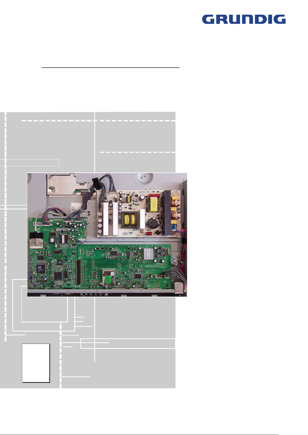
TV Service Manual
Service
Manual
Chassis
P060L46M4W2
Cinemo 40
LXW 102-8735 REF GML5300
Cinemo 46
LXW 117-8735 REF GML5400
Torreon 40
LXW 102-8790 REF GML5800
Zusätzlich erforderliche Unterlagen für den Komplettservice
Additionally required Service Documents for the Complete Service
Sicherheit
Safety
Materialnr./Part No.
720108000001
Materialnummer/Part Number 720100523000
Änderungen vorbehalten/Subject to alteration
TCC 1106 MP • Printed in Germany
http://www.grundig.com
Page 2
GRUNDIG Service Chassis P060L46M4W2
Es gelten die Vorschriften und Sicherheitshinweise
gemäß dem Service Manual "Sicherheit", Materialnummer 720108000001, sowie zusätzlich die eventuell abweichenden, landesspezifischen Vorschriften!
Inhaltsverzeichnis
Seite
Allgemeiner Teil .................................. 1-2…1-12
Allgemeine Hinweise .....................................................................1-2
Technische Daten ..........................................................................1-3
Bedienhinweise .............................................................................1-5
Service- und Sonderfunktionen ...................................................1-11
Platinenabbildungen
und Schaltpläne ..................................
Blockschaltplan ..............................................................................2-1
Netzteil ...........................................................................................2-2
Haupt-Platte ...................................................................................2-9
– VGA/HDMI-IN ..........................................................................
– IN/OUT
– Video-Konverter (UPD64015) ..................................................
– Prozessor (VCT49xyI) .............................................................
– Scaler (MST5181)
– Speicher
– Netzteil .....................................................................................
– Video-Display-Prozessor (MDIN180) .......................................2-23
– Video-Speicher ........................................................................
AV-Platte .....................................................................................2-25
– Buchsen ...................................................................................
– Tuner, SPDIF, NIMP .................................................................
– IN/OUT (CXA2069Q) ...............................................................
– Audio (MSP44xx) .....................................................................2-30
– Ton-Verzögerung (NSP-2100A) ...............................................
– Verstärker (TAS5112) ..............................................................
Buchsen-Platte ............................................................................2-33
Lautsprecherplatte .......................................................................2-34
LED/IR-Empfänger ......................................................................2-34
LED-/Lautsprecher-Platte ............................................................2-34
Keyboard .....................................................................................2-34
.....................................................................................2-13
....................................................................2-18
...................................................................................2-20
2-1…2-34
2-11
2-14
2-16
2-22
2-24
2-26
2-27
2-28
2-31
2-32
The regulations and safety instructions shall be valid
as provided by the "Safety" Service Manual, part
number 720108000001, as well as the respective
national deviations.
Table of Contents
Page
General Section .................................. 1-2…1-12
General Notes ...............................................................................1-2
Technical Data ...............................................................................1-3
Operating Hints ..............................................................................1-8
Service and Special Functions ....................................................1-11
Layout of PCBs
and Circuit Diagrams .........................
Block Circuit Diagram ....................................................................2-1
Power Supply Board ......................................................................2-2
Main Board ....................................................................................2-9
– VGA/HDMI-IN ..........................................................................
– IN/OUT
– Video Converter (UPD64015) ..................................................
– Processor (VCT49xyI) .............................................................
– Scaler (MST5181)
– Memory ....................................................................................
– Power Supply ...........................................................................
– Video Display Processor
– Video Memory ..........................................................................
AV Board .....................................................................................2-25
– Sockets ....................................................................................2-26
– Tuner, SPDIF, NIMP .................................................................
– IN/OUT (CXA2069Q) ...............................................................
– Audio (MSP44xx) .....................................................................2-30
– Sound Delay (NSP-2100A) ......................................................
– Amplifier (TAS5112) .................................................................
Socket Board ...............................................................................2-33
Speaker Board .............................................................................2-34
LED/IR Receiver ..........................................................................2-34
LED/Speaker Board .....................................................................2-34
Keyboard .....................................................................................2-34
.....................................................................................2-13
....................................................................2-18
(MDIN180) .......................................2-23
2-1…2-34
2-11
2-14
2-16
2-20
2-22
2-24
2-27
2-28
2-31
2-32
Explosionszeichnungen
und Ersatzteillisten ...............................
3-1…3-5
Allgemeiner Teil
Allgemeine Hinweise
Achtung: ESD-Vorschriften beachten
Vor dem Öffnen des Gehäuses zuerst den Netzstecker ziehen!
Leitungsverlegung
Bevor Sie Leitungen und insbesondere Masseleitungen lösen, muss die
Leitungsverlegung zu den einzelnen Baugruppen beachtet werden.
Nach erfolgter Reparatur ist es notwendig, die Leitungsführung wieder
in den werkseitigen Zustand zu versetzen um evtl. spätere Ausfälle
oder Störungen zu vermeiden.
Durchführen von Messungen
Bei Messungen mit dem Oszilloskop an Halbleitern sollten Sie nur
Tastköpfe mit 10:1 - Teiler verwenden. Außerdem ist zu beachten, dass
nach vorheriger Messung mit AC-Kopplung der Koppelkondensator
des Oszilloskops aufgeladen sein kann. Durch die Entladung über das
Messobjekt können Bauteile beschädigt werden.
Messwerte und Oszillogramme
Bei den in den Schaltplänen und Oszillogrammen angegebenen
Messwerten handelt es sich um Näherungswerte!
Austausch der Haupt-Platte
Nach Austausch der Haupt-Platte müssen alle Einstellungen im Service
Mode nach Tabelle "Grundeinstellwerte" (Punkte 1 und 2 im Kapitel
"Service- und Sonderfunktionen" auf Seite 1-11) eingestellt werden.
Exploded Views
and Spare Parts Lists ...........................
General Section
General Notes
Attention: Observe the ESD safety regulations
Before opening the cabinet disconnect the mains plug!
Wiring
Before disconnecting any leads and especially the earth connecting
leads observe the way they are routed to the individual assemblies.
On completion of the repairs the leads must be laid out as originally
fitted at the factory to avoid later failures or disturbances.
Carrying out Measurements
When making measurements on semi-conductors with an oscilloscope,
ensure that the test probe is set to 10:1 dividing factor. If the previous
measurement was made on AC input, please note that the coupling
capacitor in the oscilloscope will be charged. Discharge via the item
being checked can damage the components.
Measured Values and Oscillograms
The measured values given in the circuit diagrams and oscillograms
are approximates!
Change of the Main Board
After changing the main board all settings in the service mode must be
done according to the table "Basic Settings" (points 1 and 2 in chapter
"Service and Special Functions" on page 1-11).
1 - 2
3-1…3-5
Page 3
Chassis P060L46M4W2GRUNDIG Service
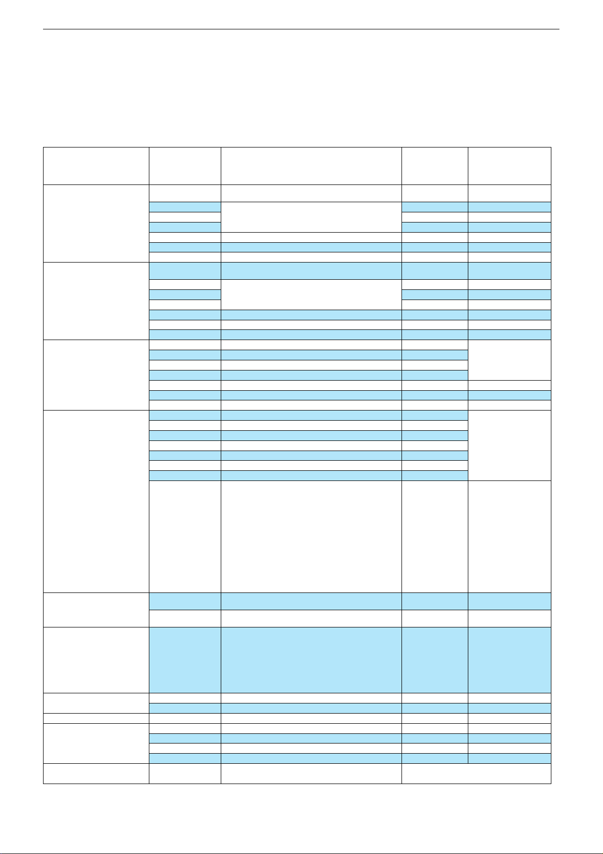
Technische Daten / Technical Data
Order No.
Destination
Approbations
IM-Languages
Remote control
EAN
Color
DISPLAY
Panel
Display-Manufacturer
16:9 wide-screen format
Response time
Brightness
Contrast ratio (Panel)
Viewing angle approx.
Physical display resolution max. pixel
PICTURE
Digital Reference Plus
Motion Compensative Deinterlacing
Motion Adaptive Deinterlacing
Natural view HD Reference
Full HD
Line Flicker Reduction
Digital Color Transition Improv. (DCTI)
Digital Combfilter
Digital Luminace Transition Improv. (DLTI)
Picture Noise Reduction (DNR)
CCS (Clear Color Screen)
Preset picture modes
Picture Status Memory
Aspect ratios (Format switching)
Blackline detection
PIP
Multifold Tuner scan (Mosaic Picture)
PAT: Split screen (PICTURE + TEXT)
PAP: Double Window (PICTURE + PICTURE)
P2AT: Double Window + TXT
POP: PICTURE on PICTURE
Picture freezing
Zoom with point function
Auto 16:9 selection via Scart
Sharpness control
Blue Background
CHASSIS
Progressive
Tuner
Keyboard
Cinemo 40 LXW 102-8735 REF Cinemo 46 LXW 117-8735 REF Torreon 40 LXW 102-8790 REF
D,GB,F,I,NL,DK,N,S,FIN,E,P,PL,CZ
D, CH, F, I, E, P, NL, Nordic, PL, CZ, HR
40" / 102 cm Active Matrix TFT-LC-Display
5 Mode - Dynamic, Standard, Mild, Game, User
7 keys: stand-by, menue, ± for programme,
TP 170 C (black)
40 13833-60922 3
Samsung LTA400WS-L02
Super High Speed PVA-Panel
178° vertical / 178° horizontal
WXGA 1366 x 768
4 Mode - Cool, Warm, Normal, User
Auto WSS, 4:3 / 14:9 / 16:9 /
Zoom 1 / Zoom 2 / Spectacle
PLL frequency synthesizer tuning
± for volume, input select
G.ML 53-00
CE,I
D,GB,F,I,NL,DK,N,S,FIN,E,P,PL,CZ
D, CH, F, I, E, P, NL, Nordic, PL, CZ
black black
46" / 117 cm Active Matrix TFT-LC-Display
[
8ms
500cd/m2
ca. 1.200:1
[[
[
[
\
\
[
[
(3D)
[
[
[
\
\
1-Tuner PIP
4 & 16-Freeze
\
[
\
[
[
\
[
[
\\
[
4 Mode - Cool, Warm, Normal, User
5 Mode - Dynamic, Standard, Mild, Game, User
7 keys: stand-by, menue, ± for programme,
G.ML 54-00
CE,I
TP 170 C (black)
40 13833-60923 0
Samsung LTA460WS-L03
Super High Speed PVA-Panel
178° vertical / 178° horizontal
Auto WSS, 4:3 / 14:9 / 16:9 /
Zoom 1 / Zoom 2 / Spectacle
PLL frequency synthesizer tuning
[
8ms
500cd/m2
ca. 1.200:1
WXGA 1366 x 768
[
[
\
\
[
[
[
(3D)
[
[
\
\
1-Tuner PIP
4 & 16-Freeze
\
[
\
[
[
\
[
[
[
± for volume, input select
D,GB,F,I,NL,DK,N,S,FIN,E,P,PL,CZ
D, CH, F, I, E, P, NL, Nordic, PL, CZ
40" / 102 cm Active Matrix TFT-LC-Display
4 Mode - Cool, Warm, Normal, User
5 Mode - Dynamic, Standard, Mild, Game, User
PLL frequency synthesizer tuning
7 keys: stand-by, menue, ± for programme,
G.ML 58-00
CE,I
TP 170 C (black)
40 13833-60926 1
silver/black
Samsung LTA400WS-L02
Super High Speed PVA-Panel
178° vertical / 178° horizontal
Auto WSS, 4:3 / 14:9 / 16:9 /
Zoom 1 / Zoom 2 / Spectacle
[
8ms
500cd/m2
ca. 1.200:1
WXGA 1366 x 768
[
[
[
\
\
[
[
(3D)
[
[
[
\
\
1-Tuner PIP
4 & 16-Freeze
\
[
\
[
[
\
[
[
\
[
± for volume, input select
1 - 3
Page 4
Chassis P060L46M4W2GRUNDIG Service
ELECTRONIC
Stand by indicator
EPG (Electronic Programme Guide)
Easy Dialog
Megalogic
Manual & autom. labeling of prog.
Programmable off timer
Programmable on timer
Intelligent channel search (Zapping funct.)
Programme Edit
Intelligent Programme Switch
Auto switch off
Program memory TV/AV (opt.)
Teletext/Fasttext/Toptext
Teletext options
Childlock
Menue languages OSD
OSD-style
SWAP (Recall function)
Service mode
Hotel mode
TUNING
Autom. Tuning System with country selection
Frequency Based Auto Search
Automatic Micro-search
Automatic Programming
Manual fine tuning
Direct channel selection
Direct frequency selection
TV-Norm
NTSC-Playback via Scart (3,58/4,43)
Cable TV / Hyperband (S1-S41)
AUDIO
Mono/Stereo/Nicam
AV Stereo
Loudspeaker
Virtual Dolby
Magic Fidelity Sound System
Matched Sound Delay (Lip synchronous)
Subwoofer
Dynamic Bass
DSP (Digital Sound Processor)
Balance Adjustment
AVL (Audio Volume Level)
PIP listening via Headphone.jack
Equalizer
Space Sound Effect
Audio mode
Audio amplifier
DVB reception
DVB-T/S/C
POWER SUPPLY / CABINET
Power voltage
Range of regulation
Power switch
Integrated supply
Plug-in AC adaptor
Power consumption
Cabinet (WxHxD, cm) / Weight
FRONT PANEL CONNECTIONS
Headphones
Cinch-AV socket
S-Video
USB
Digital Media Player
YUV input / progressive
REAR PANEL CONNECTIONS
Euro-AV-Socket AV1
Euro-AV Socket AV2
Euro-AV Socket AV3
S-Video
Camera-AV
Wireless
YUV input / progressive
PC-input
PC-Audio in
DVI
HDMI
HD ready including HDCP
Headphones
Digital Audio out optical (SPDIF)
Video out
Audio out
Antenna for terrestrial reception
DC-connector
Power supply plug
SUPPLIED ACCESSORIES
Remote control (incl. battery)
Power cord
Cables
Instruction manual
Circuit diagram
Wall fixture
Warning sticker in rear panel
Warranty info
Cinemo 40 LXW 102-8735 REF Cinemo 46 LXW 117-8735 REF Torreon 40 LXW 102-8790 REF
red LED
\
\
\
[
[
[
\
[
\
stand-by
99 / 8
[
/ [ /
[
1000 pages
[
Grundig-style
[
[
\
full automatic sorting full automatic sorting
[
\
\
[
[
PAL/SECAM/BG/DK/I/L'/L
5 Mode - Flat, Music, Movie, Speech, User
[
[
[[
[
/ [ /
[
[
\\
\
\
\
\
[
[
[
\
7 Band
[
2x 20W (RMS)
13 languages, D, GB, F, I, E, P, NL, DK, FIN, N, S, PL, CZ
Super Woofer System SRS TruSurround XT Digital
5 Mode - Flat, Music, Movie, Speech, User
Retrofitting possible via Scart socket
100 - 240V, 50/60Hz; in accordance to IEC 65 100 - 240V, 50/60Hz; in accordance to IEC 65
90-264V, 50/60Hz, in accordance to IEC 65
240W, stand-by < 3W in accordance to
99,8 x 80,5 x 12,8 cm (30,6 cm with stand) /
3 x Cinch - Video in, Audio in L/R (side)
Video-in: 3 x Cinch, Audio-in: 2 x Cinch (side) Video-in: 3 x Cinch, Audio-in: 2 x Cinch (side)
Video-in: 3 x Cinch, Audio-in: 2 x Cinch
1-pole
[
\
IEC 62087-2002
approx. 33,85 kg
\\
Hosiden (side)
\
\
CVBS in-/output, RGB input
CVBS in-/output
CVBS in
\
\
\
Multisync WXGA
[
\
2x
via HDMI
\
[
\
\
\\
[[
[
(grounded)
\
[
[
(V) 216 x (H) 688
[
[
90-264V, 50/60Hz, in accordance to IEC 65
280W, stand-by < 3W in accordance to
114,2 x 90,6 x 12,8 cm (35,5 cm with stand) /
3 x Cinch - Video in, Audio in L/R (side)
Video-in: 3 x Cinch, Audio-in: 2 x Cinch
1 x Coaxial-socket for TV-tuner-in, according to DIN 45325
TP 170 C black, running change TP 170 C black glossy
red LED
\
\
\
[
[
[
\
[
\
stand-by
99 / 8
[
/ [ /
[
1000 pages
[
Grundig-style
[
[
\
[
\
\
[
[
[
/ [ /
7 Band
[
[
[
[
\
\
\
\
[
[
[
\
[
PAL/SECAM/BG/DK/I/L'/L
2x 25W (RMS)
DVB-T: DTR 1560 Micro
DVB-S: DSR 1650 Micro
DVB-C: DCB 1680 Micro
1-pole
[
\
IEC 62087-2002
approx. 46,2 kg
Hosiden (side)
\
\
CVBS in-/output, RGB input
CVBS in-/output
CVBS in
\
\
\
Multisync WXGA
[
\
2x
via HDMI
\
[
\
\
[
(grounded)
\
[
[
(V) 216 x (H) 688
[
[
5 Mode - Flat, Music, Movie, Speech, User
100 - 240V, 50/60Hz; in accordance to IEC 65
90-264V, 50/60Hz, in accordance to IEC 65
240W, stand-by < 3W in accordance to
99,8 x 80,5 x 12,8 cm (30,6 cm with stand) /
3 x Cinch - Video in, Audio in L/R (side)
Video-in: 3 x Cinch, Audio-in: 2 x Cinch (side)
Video-in: 3 x Cinch, Audio-in: 2 x Cinch
red LED
\
\
\
[
[
[
\
[
\
stand-by
99 / 8
[
/ [ /
1000 pages
[
Grundig-style
[
[
\
full automatic sorting
[
\
\
[
[
[
/ [ /
7 Band
[
[
[
[
\
\
\
\
\
[
[
[
\
[
PAL/SECAM/BG/DK/I/L'/L
2x 20W (RMS)
1-pole
[
\
IEC 62087-2002
approx. 33,85 kg
\
Hosiden (side)
\
\
CVBS in-/output, RGB input
CVBS in-/output
CVBS in
\
\
\
Multisync WXGA
[
\
2x
via HDMI
\
[
\
\
\
[
(grounded)
[
\
[
[
(V) 216 x (H) 688
[
[
[
[
1 - 4
Page 5
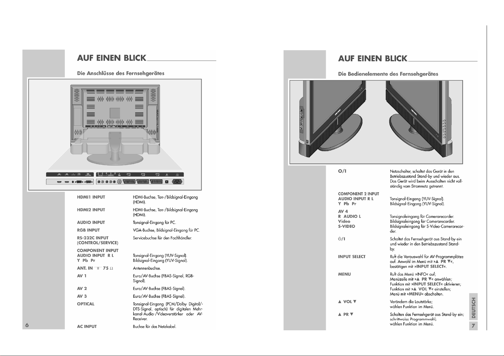
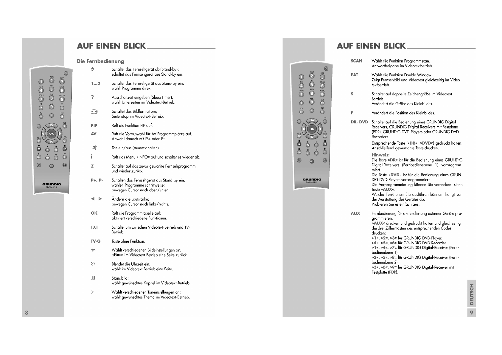
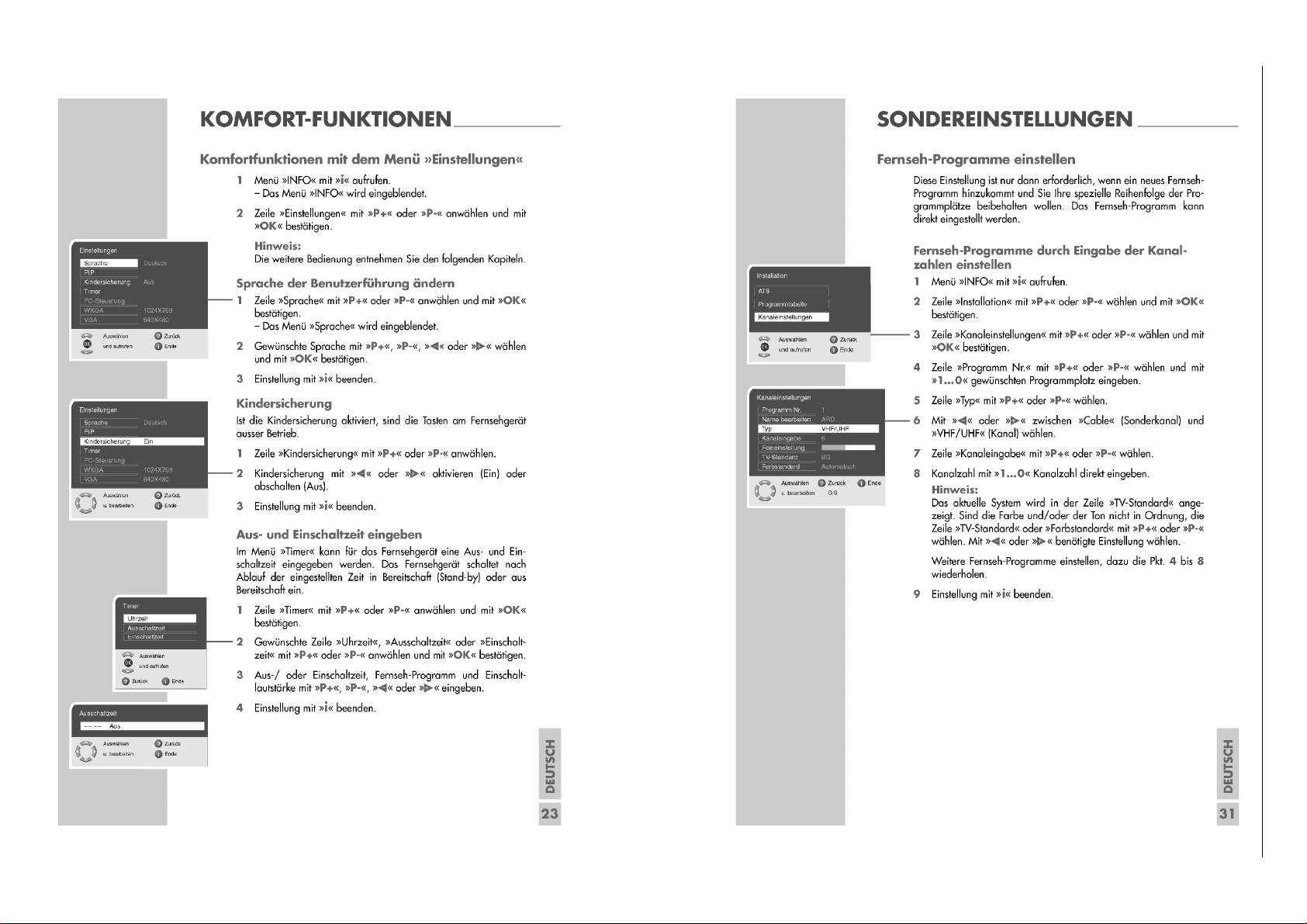
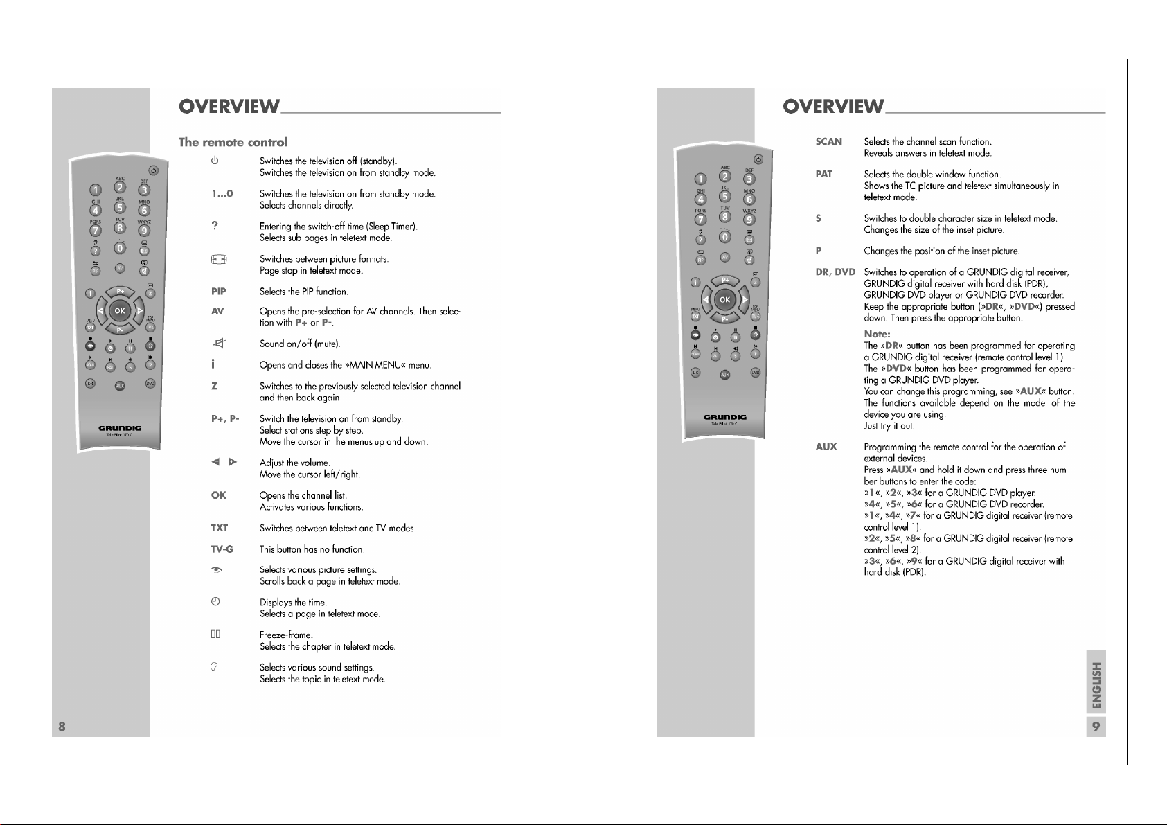
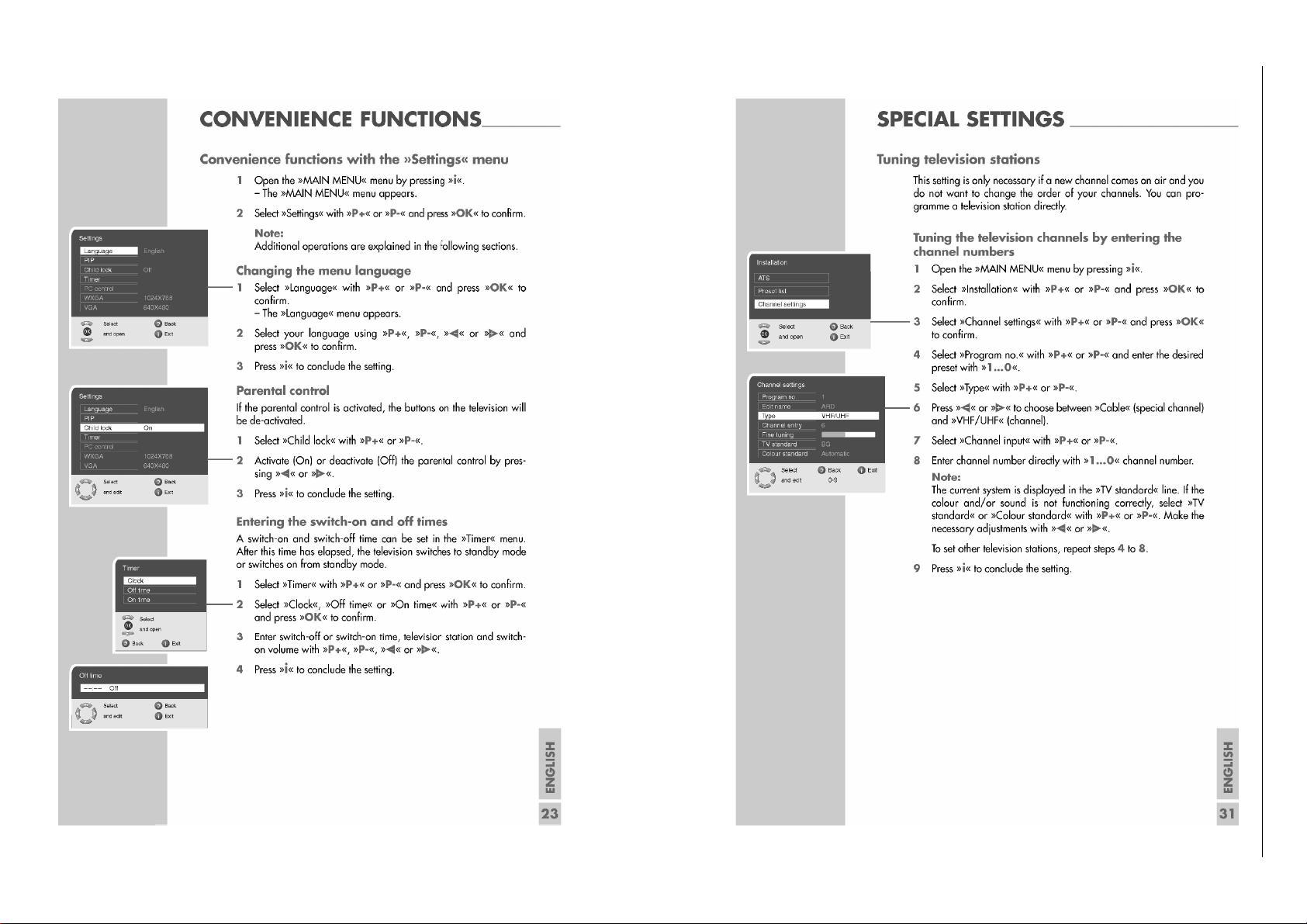
Bedienhinweise Dieses Kapitel enthält Auszüge aus der Bedienungsanleitung.
Weitergehende Informationen entnehmen Sie bitte der gerätespezifischen Bedienungsanleitung, deren Materialnummer Sie in der entsprechenden Ersatzteilliste finden.
1 - 5
Chassis P060L46M4W2GRUNDIG Service
Chassis 22.2GRUNDIG Service
Page 6
1 - 6
1 - 6
Chassis P060L46M4W2GRUNDIG Service
Chassis D-32IE11GRUNDIG Service
Chassis 22.2GRUNDIG Service
Page 7
1 - 7
Chassis P060L46M4W2GRUNDIG Service
Page 8
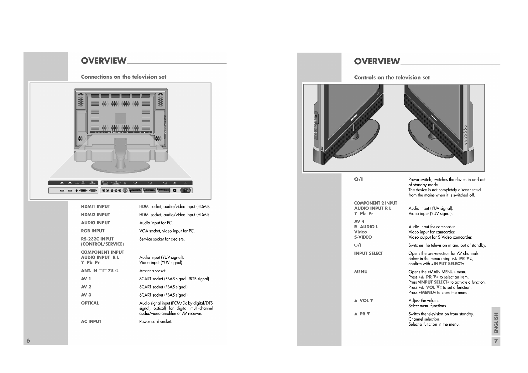
Operating Hints This chapter contains excerpts from the operating instructions.
For further particulars please refer to the appropriate user instructions the part number of which is indicated in the relevant spare parts list.
1 - 8
Chassis P060L46M4W2GRUNDIG Service
Chassis 22.2GRUNDIG Service
Page 9
1 - 9
Chassis P060L46M4W2GRUNDIG Service
Chassis 22.2GRUNDIG Service
Page 10
1 - 10
Chassis P060L46M4W2GRUNDIG Service
Page 11
Chassis P060L46M4W2GRUNDIG Service
Service- und Sonderfunktionen
Service Mode aktivieren: Ta s te " i " –> Service Code "8500"
Menü aufrufen: Ta st e
Einstellung verändern: Taste
Menü verlassen: Tast e " i "
Service Mode beenden: Taste " i " nach Verlassen des Menü
1. Grundeinstellwerte
Folgende Tabelle zeigt Grundeinstellungen im Service Mode.
Menü
Menu
P+ / P–
WHITE BALANCE
(COMP1, COMP2)
WHITE BALANCE
(PC-RGB)
SOUND
OPTION1
OPTION2
OPTION3
POWER MODE
MICOM RESET
MEMORY-CLOCK SET
PANEL TYPE
P+ / P–
–> Taste "OK"
Ǹ / Ƿ bzw. "OK"
Menüpunkt
Point of Menu
P+ / P–
AUTO-CUTOFF
R-DRIVE
G-DRIVE
B-DRIVE
R-CUTOFF
G-CUTOFF
B-CUTOFF
AUTO-CUTOFF
R-DRIVE
G-DRIVE
B-DRIVE
R-CUTOFF Cut off-Wert "rot" / Cut off value "red"
G-CUTOFF
B-CUTOFF
DUAL
A2 STEREO
DOLBY
WOOFER
SC PRESCALE
FM PRESCALE
NICAM PRESCALE
CHINA
TEXT
TXT LIST MODE
TXT-TOP
TXT-ACMS
DTV-TXT
GAME
TXT-LANG
200PR
SYSTEM
OSD LANGUAGE
POWER MODE
Auto Search
DQSPH0
DQSPH1
DQSPH2
DQSPH3
PANEL1
automatischer Schwarzabgleich / Auto cutoff Control
ohne Funktion
without Function
Cut off-Wert "rot" / Cut off value "red"
Cut off-Wert "grün" / Cut off value "green"
Cut off-Wert "blau" / Cut off value "blue"
automatischer Schwarzabgleich / Auto cutoff Control
ohne Funktion
without Function
Cut off-Wert "grün" / Cut off value "green"
Cut off-Wert "blau" / Cut off value "blue"
2-Kanal-Ton / Dual sound
A2 Stereo
Dolby-Ton / Sound
Bass-Lautsprecher / Woofer sound
Tonpegel-Euro-AV / Scart Output Level Control
Tonpegel-FM / FM sound Level Control
Tonpegel-Nicam / Nicam Sound Level Control
China-Kanaltabelle / Channel Table
TeleText
Teletext-List Betrieb / Mode
TeleText TOP
Tex tText ACMS
DTV Text
Spiele / Game mode
Teletext-Sprache / TeleText Language
200-Seiten-Programmierung / 200 Page Programming
TV-Norm / RF System
OSD-Sprache (Basis) / Default OSD Language
Automatische Abschaltung / Auto Sleep Control
ATS-Reset
µP-Reset
Speichertakt / Memory Clock Setting
Speichertakt / Memory Clock Setting
Speichertakt / Memory Clock Setting
Speichertakt / Memory Clock Setting
LPL-Weißbalance / LPL White Balance Setting.
(WS-L01, WS-L02, WS-L03, WS-L11)
Service and Special Functions
Start of the Service Mode: Via " i " –> Service Code "8500"
Call up the Menu: Press button
Adjustment: Press button
Break of the Menu: Press button " i "
End the Service Mode: Press button " i " after break of Menu
1. Basic Settings
The following table shows basic settings in the service mode.
Beschreibung
Description
Einstellung
Adjustment
Ǹ / Ƿ
OK
siehe Punkt 2
see point 2
–
–
–
128
123
127
siehe Punkt 2
see point 2
–
–
–
131
131
131
1
1
0
0
27
19
70
0
1
1
1
1
0
0
0
0
1
1
OFF
OFF
2
1
2
1
eingebautes Display wählen
select used display
P+ / P–
Ǹ / Ƿ or "OK"
Aus / Off = 0
Aus / Off = 0
West Europe = 0
East Europe = 1
Czecho/Hungary = 3
Turkey/Greek1 = 7
Turkey/Greek2 = 8
Turkey/Greek3 = 9
Arab/France = 10
Arab/English = 11
Arab/Hebrew1 = 12
Arab/Hebrew2 = 13
Farsi/English = 14
Farsi/France = 15
Aus / Off = 0
BG/I/DK/L = 1
BG/I/DK/M = 2
Portuguêsa = 6
Nederlands = 10
–> button "OK"
Hinweis
Hint
Ein / On = 1
Ein / On = 1
Turkey = 2
Cyrillic1 = 4
Cyrillic2 = 5
Cyrillic3 = 6
Farsi All = 16
Ein / On = 1
Englisch = 0
Deutsch = 1
France = 3
Italiano = 4
Español = 5
Dansk = 7
Svenska = 8
Suomi = 9
2 - 11
1 - 11
Page 12

Chassis P060L46M4W2GRUNDIG Service
Menü
Menu
P+ / P–
MDIN Reg1
MDIN Reg2
Menüpunkt
Point of Menu
P+ / P–
Sharpness gain
LTI gain
CTIB gain
CTIR gain
Contrast
Brightness
Cb saturation
Cr saturation
Cb offset
Cr offset
Mo1
Mo2
Nr offset1
Nr offset2
Nr on/off
Sel BW Func
Schärfeeinstellung / Sharpness setting
Helligkeits-Übergangs-Verbesserung / LTI gain setting
Farb-Übergangs-Verbesserung B / CTIB gain setting
Farb-Übergangs-Verbesserung R / CTIR gain setting
Kontrast / Contrast setting
Helligkeit / Britghtness setting
Farbsättigung B / Cb saturation setting
Farbsättigung R / Cr saturation setting
Farb-Offset B / Cb offset setting
Farb-Offset R / Cr offset setting
Bewegungseinstellung 1 / Motion 1 setting
Bewegungseinstellung 2 / Motion 2 setting
Offset Nr. 1 / Nr. 1 offset setting
Offset Nr. 2 / Nr. 2 offset setting
Nr. Ein/Aus / Nr. on/off setting
Schwarz-/Weiß-Einstellung / Select BW function setting
2. Abgleich "Cut off"
Dieser Abgleich ist jeweils in den Betriebsarten "PC-RGB" und
"Component Mode" (COMP. 1 / COMP. 2) im betriebswarmen Zustand (min. 15 Minuten nach dem Einschalten) durchzuführen.
– Testbild "Schwarz" einspeisen am RGB-Eingang (VGA) oder
Component-Eingang (COMP. 1 / COMP. 2).
– AV-Eingang wählen: Tasten
AV
–> P+ /
P–
"PC-RGB" oder
"COMP. 1" / "COMP. 2" –> "OK"
– Bildeinstellung "Standard" mit der Taste
– Service-Funktion "Auto-Cutoff" aufrufen: Tasten "
vice Code "8500" –> P+ /
P–
"White Balance" –> "OK" –> P+ /
o wählen.
i " (Info) –> Ser-
P–
"Auto-Cutoff" –> "OK".
– Testbild "Grautreppe" einspeisen.
– Service-Funktionen "R-CUTOFF", "G-CUTOFF" und "B-CUT-
OFF" nacheinander aufrufen (mit den Tasten
P+ / P–
–> "OK") und
mit den Tasten Ǹ / Ƿ so einstellen, dass alle Grauabstufungen
der Grautreppe erkennbar und unbunt sind.
3. Austausch der Haupt-Platte
Nach Austausch der Haupt-Platte müssen alle Einstellungen im
Service Mode nach Tabelle "Grundeinstellwerte" (Punkt 1) durchgeführt werden.
4. Programmsuchlauf
Taste n "
"ATS" –> "OK" –> P+ /
i " (INFO) –>
P–
P+ / P–
"Installation" –> "OK" –> P+ /
"Suchen" und mit "OK" Suchlauf starten.
P–
Das automatische Sendersuchsystem stoppt bei jedem empfangswürdigen Sender (AFC und Koinzidenz) und speichert automatisch
die entsprechenden Senderdaten mit dem jeweiligen Standard. Danach wird der Suchlauf fortgesetzt.
Tastendruck "
i " bricht den Suchlauf ab.
5. Software-Versionsnummer
Die Software-Versionsnummer wird im Service Menü angezeigt:
z.B. VER 1.003 06/09/25
Beschreibung
Description
Einstellung
Adjustment
Ǹ / Ƿ
OK
7
2
24
24
512
0
512
512
3594
3594
14
15
4
4
1
0
2. Adjustment "Cut off"
These adjustments must be accomplished at operating state temperature (min. 15 minutes after switch on) in mode PC-RGB and component mode (COMP. 1 / COMP. 2).
– Feed in a black test pattern at RGB input (VGA) or Component
input (COMP. 1 / COMP. 2).
– Call up the AV input: Buttons
AV
–> P+ /
P–
"COMP. 1" / "COMP. 2" –> "OK"
– Select the picture setting "Standard" with button
– Call up the Service Function "Auto-Cutoff": Buttons "
Service Code "8500" –> P+ /
P+ / P–
"Auto-Cutoff" –> "OK".
P–
"White Balance" –> "OK" –>
– Feed in a greyscale test pattern.
– Call up step by step the Service Functions "R-CUTOFF", "G-CUT-
OFF" and "B-CUTOFF" (with buttons
P+ / P–
–> "OK") and adjust
with buttons Ǹ / Ƿ so that the gradings of the greyscale test pat-
tern are visible and achromatic.
3. Change of the Main Board
After changing the main board all settings in the service mode must
be done according to the table "Basic Settings" (point 1).
4. Autoprogram
Buttons "
P+ / P–
i " (MAIN MENU) –>
"ATS" –> "OK" –> P+ /
P+ / P–
P–
"Installation" –> "OK" –>
"Search" and start search with
"OK".
The autoprogram system stops at every station of acceptable reception quality (AFC and coincidence) and stores the station data
and the respective standard automatically. The system then continues searching.
Pressing the "
i " button stops the programme search.
5. Software Version Number
The software version number is shown in the Service Menu:
e.g. VER 1.003 06/09/25
Hinweis
Hint
"PC-RGB" or
o.
i " (Info) –>
1 - 12
Page 13
Platinenabbildungen und Schaltpläne / Layout of PCBs and Circuit Diagrams
UXF-CLK,TW_H/V//DE/FIELD
TV-V
RGB_PC/DTV
T
UNER
Component 1
HDMI(DVI)
S
- VIDEO/CVBS
Component 2
Half SCART
CU
T
O
F
F
S
CAR
T
SIF/AM-AUDIO
Y/C1,L1/R1
V5,L5/R5
V2,L2/R2
V1,L1/R1
T
R
Y1/Pb1/Pr1
T
R
Y2/Pb2/Pr2
A
T24C02N
I2C
AT24C0
2
N
Full SC
ART
V1,L1/R1
SCART ID1
S2-1
SCART FB/R/G/B
TV-O
74
HCT14D
PC-H/V
DVI_Rx
I2C
PC-R/G/B
SCART ID2
V2,L2/R2
S2-2
SCART2-V
V5,L5/R5
SCART ID3
S2-3
YC3,R3/L3
TV-V
NIMP_VO/LO/RO
L6/R6
NIMP-.656
SCART2-VO/LO/RO
NIMP_AUDIO_-L/R
TV-O
TV-L/R
HDMI_Rx
NIM
P
UPD
6
4015A
UPD
6
4015A
COMP1 Y2/Pb2/Pr2
V OUT-M
Y OUT-M
C OUT-M
TV-L/R
CXA-R/L
COMP1-Y2/Pb2/Pr2
COMP1-Y1/Pb1/Pr1
COMP2-Y2/Pb2/Pr2
COMP2-Y1/Pb1/Pr1
PI3V
512
Optical
Out
I2S/PWM
L-Out
R-Out
SIF/AM-AUDIO
I2S-MST
R
L
TV-L/R
COMP1-L/R
COMP2-L/R
CXA-R/L
MSP4450K
SCL-A
AMP
NSP5112
SDA-A
SC4
SC1
SC2
SC3
SPDIF-OUT
SPDIF
SDRAM-16M
NSP2100
Comp2_L/R
Comp1_L/R
SDRAM- 64M
SCART_FB
/R1/G/1B1
TW-H/V/CLK/DE/FIELD
TW_Y[0..7]
UXF-.656
UXF_CLK
YV[0..7]
DECCLK
I2S-MST
PANEL
PI3V
512
COMP2-Y1/Pb1/Pr1
PI3V
512
SU-L/R
TR
SC-L/R
UX-L/R
BSS83(5V)
CNTL-SDA
CNTL-SCL
SDA-A
SCL-A
DDR SDRAM
MDATA[0..31]
AR[0..11]
2.5V
2.5V
3.3V
1.8V
2.5V3.3V
27MHz
9V
24V
9V
14.318MHz
53
59
58
63
40.44.46
41.43.47
TAD[0..10]
TDQ[0..15]
ITU-R 656[YT,7
…
0]
56
58
62,64
1,2,4
8,9,11
43~45
24V 5V
M
S
T518
1
A
24,27,29
22,23
32,,35,37
48~76
66,67,68,95
234~244
251
3~13
18.19
189,190,191
6
C
XA2069Q
29,30,31
27
15~18
63
61,60,59
13
PC_AUDIO
PC_AUDIO_L/R
23,25
MDIN-H/V/CLK/DE/FIELD
MDIN_R/G/B[0..7]
MDIN-H/V/CLK/DE/FIELD
MDIN_R/G/B[0..7]
Y OUT-S
V OUT-S
C OUT-S
VCT49xyI
SRAM
8Mbit
Flash
ADB[0..19]
ADB[0..19]
Key
AD_Key2
AD_Key1
TX_INT
LED_R/G
SCART_FB/R1/G/1B1
YV[0..7]
DECCLK
1.8V
3.3V
20.25MHz
5V
61
64
65
67.68.69
46
45
44
39
40
DECCLK
M
DIN
1
8
0
INPUT B
H16
INPUT A
40
M
DIN
1
8
0
INPUT B
H16
INPUT A
40
YV[0..7]
RS- 232
UART_RX/TX
81,82
SDRAM
MA[0..12]
MDA[0..63]
27MHz
1.8V
3.3V
M65856
MIC
18.432MHz
2MHz
PI
HDMI
412
Without NIMP With NIMP
Always
A
T
24
C02N
HDMI(DVI)
CF SLOT
SD SLO
T
US
B Jack
REX3+
200
REX3-
201
REXC+
204
REXC-
205
REX2+
206
REX2-
207
REX1+
208
REX1-
209
REX0+
210
REX0-
211
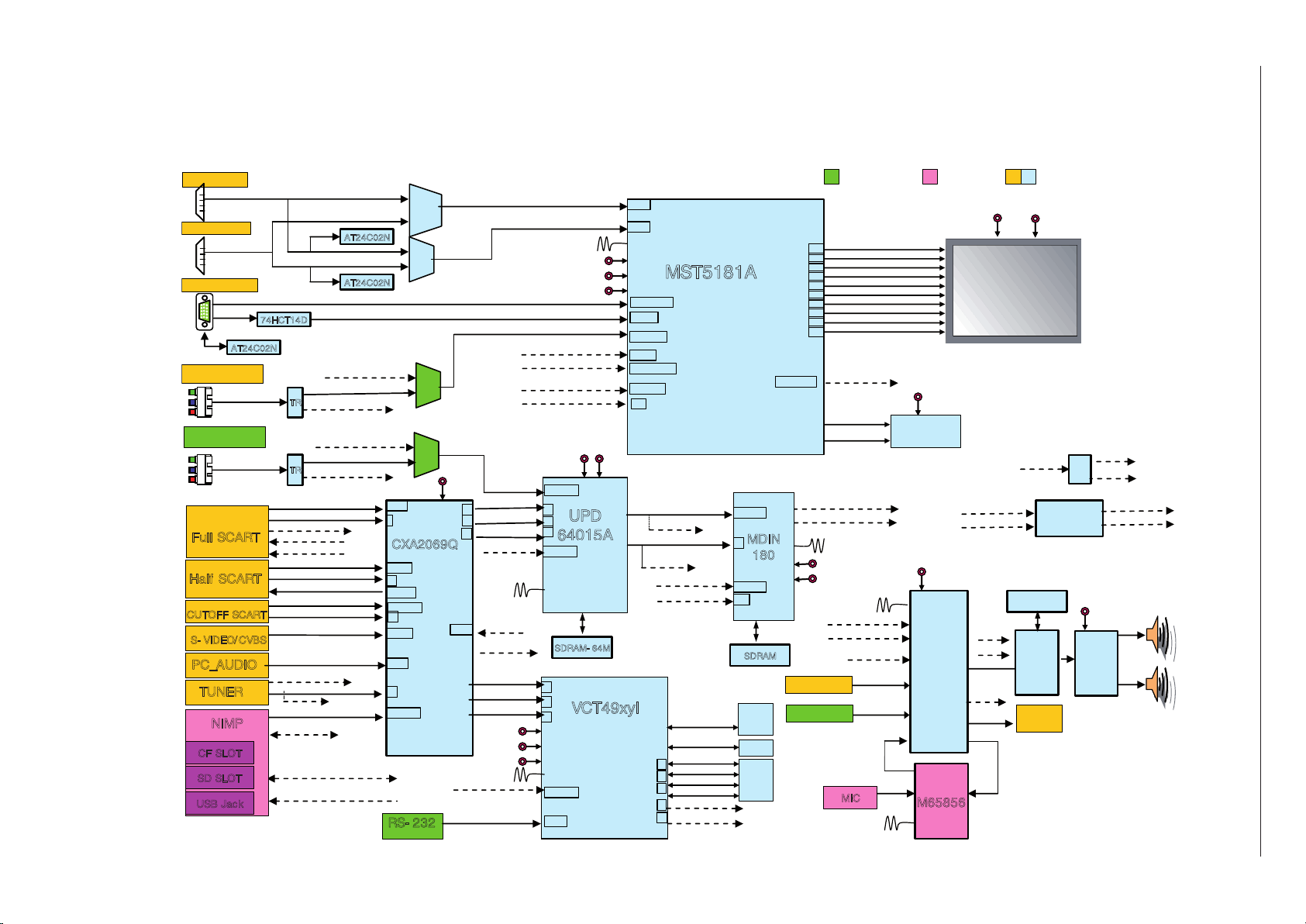
Blockschaltplan / Block Circuit Diagram
GRUNDIG Service Chassis P060L46M4W2
2 - 1
Page 14
Netzteil-Platte / Power Supply Board 40“
Ansicht von der Bestückungsseite / View of Component Side
2 - 2
GRUNDIG Service Chassis P060L46M4W2
Page 15
Netzteil-Platte / Power Supply Board 40“
Ansicht von der Lötseite / View of Solder Side
2 - 3
GRUNDIG Service Chassis P060L46M4W2
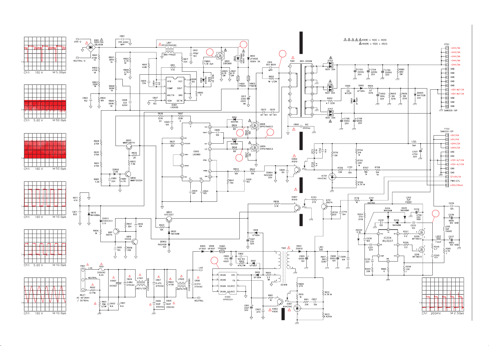
Page 16
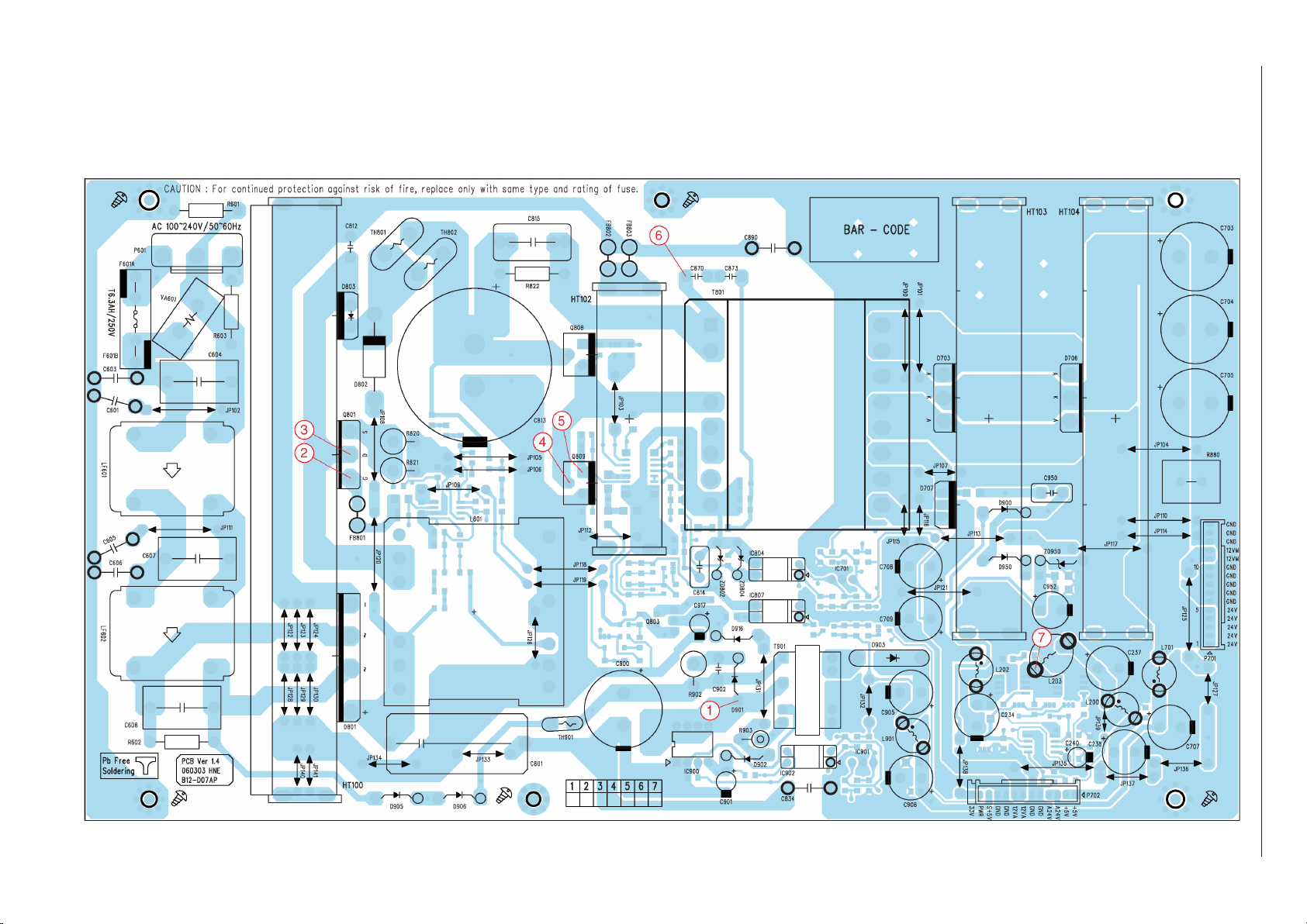
7
1
5
4
6
4
3
2
Netzteil-Platte / Power Supply Board 40“
1
2
3
4
5
6
7
GRUNDIG Service Chassis P060L46M4W2
to P. 2-22
P804
to P. 2-22
P803
2 - 4
IC Block Diagrams, see P. 2-8
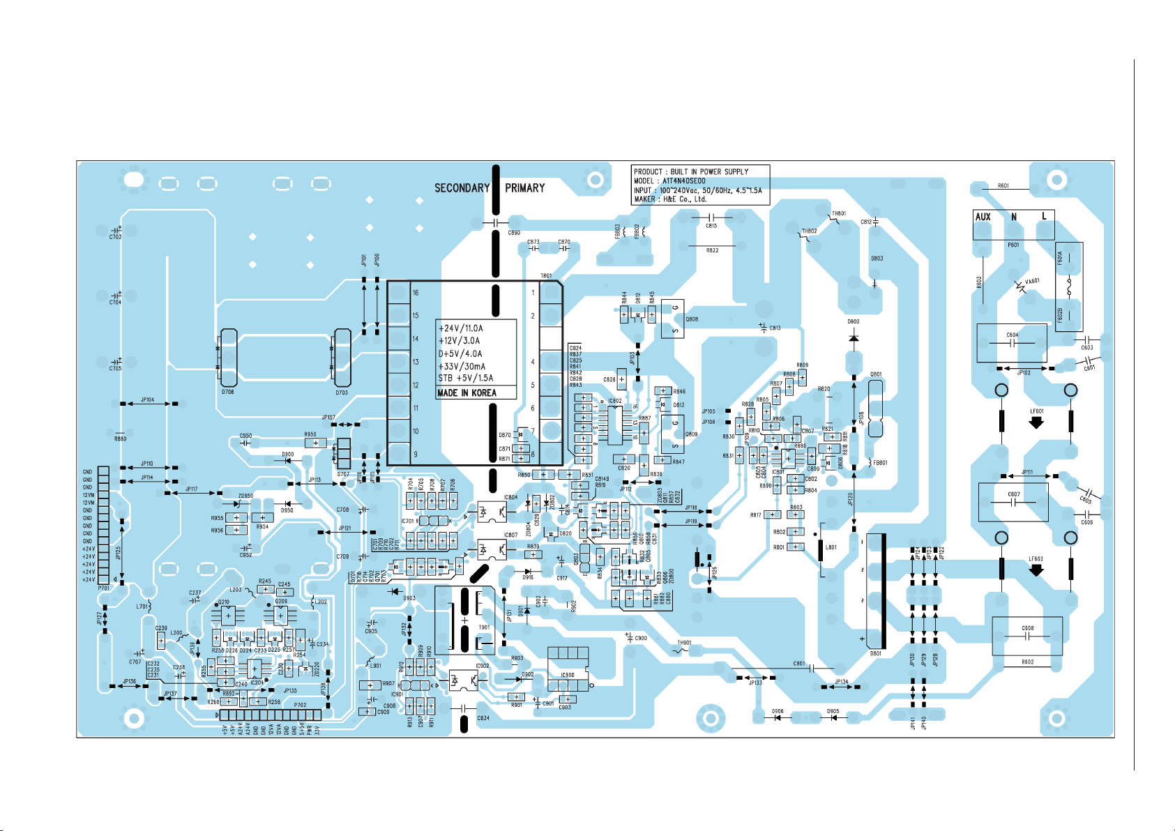
Page 17

Netzteil-Platte / Power Supply Board 46“
Ansicht von der Bestückungsseite / View of Component Side
2 - 5
GRUNDIG Service Chassis P060L46M4W2
Page 18

Netzteil-Platte / Power Supply Board 46“
Ansicht von der Lötseite / View of Solder Side
2 - 6
GRUNDIG Service Chassis P060L46M4W2
Page 19

7
1
5
4
6
4
3 2
Netzteil-Platte / Power Supply Board 46“
1
2
3
4
5
6
7
GRUNDIG Service Chassis P060L46M4W2
2 - 7
to P. 2-22
P805
to P. 2-22
P804
to P. 2-22
P803
IC Block Diagrams, see P. 2-8
Page 20

Current
Limit
Thermal
Shutdown
Vref
Vin, Power
Output
Sense
Adj
V
CNTL
, Control
2
1
3
5
4
Voltage Loop
Amplifier
FAN1581
+
-
MULTIPLIER AND
THD OPTIMIZER
V
REF2
OVERVOLTAGE
DETECTION
VOLTAGE
REGULATOR
UVLO
INTERNAL
SUPPLY 7V
+
-
2.5V
R1
R2
RSQ
+
-
DRIVER
STARTER
+
-
ZERO CURRENT
DETECTOR
DISABLE
2.1 V
1.6 V
VCC
8
1
432
ZCD
V
CC
INV
SCTLUMPMOC
GD
7
5
GND
6
25 V
40K
5pF
15 V
Starter
stop
L6562
GND
V
REF
Ifmin
VCO
EN1
Vthe1
Vthe2
EN2
V
S
V
BOOT
OUT
LVG
UV
DETECTION
Vs
HVG
BOOTSTRAP
DRIVER
HVG
DRIVER
LVG DRIVER
V
REF
Ifstart
OP AMP
+
-
OPOUT
OPIN-
OPIN+
DEAD
TIME
DRIVING
LOGIC
CONTROL
LOGIC
Iss
+
-
+
-
LEVEL
SHIFTER
12
5
6
7
4
2
3
1
9
8
10
11
14
15
16
L6598
ON/OFF
0.23V
DRAIN
SOURCE
VDD
PWM
LATCH
60kHz
OSCILLATOR
BLANKING
+
_
8/14.5V
_
+
FF
S
R1
R4QR3
FB
REGULATOR
INTERNAL
SUPPLY
OVERVOLTAGE
LATCH
DETECTOR
1 k
Ω
42V
_
+
R2
FF
SRQ
230
Ω
VIPER 22
AN2097
Voltage Loop
Compensation
Protection Unit
Fixed
Oscillator
Current Loop
Compensation
PWM Logic
Driver
ICE1PCS02 /G
CCM PFC
VCC
Ramp
Generator
ICOMP
VSENSE
VCOMP
ISENSE GND
Nonlinear
Gain
GATE
VINS
Brown-out
1
5
6
7
3
2
8
4
GRUNDIG Service Chassis P060L46M4W2
2 - 8
Page 21

GRUNDIG Service Chassis P060L46M4W2
Haupt-Platte / Main Board
Ansicht von der Bestückungsseite / View of Component Side
2 - 9
Page 22

GRUNDIG Service Chassis P060L46M4W2
Haupt-Platte / Main Board
Ansicht von der Lötseite / View of Solder Side
2 - 10
Page 23

13
14
11
12
!
@
#
$
GRUNDIG Service Chassis P060L46M4W2
Haupt-Platte / Main Board – VGA/HDMI-IN
2 - 11
Page 24

PI3V512
SEL
2
5
6
8
11
12
OUT_A
OUT_B
OUT_C
OUT_D
OUT_E
24
23
22
21
18
17
16
15
14
13
A0
A1
B0
B1
C0
D0
C1
D1
E0
E1
PI3HDMI412
GRUNDIG Service Chassis P060L46M4W2
Haupt-Platte / Main Board – VGA/HDMI-IN
to P. 2-34
PK101
2 - 12
Page 25

GRUNDIG Service Chassis P060L46M4W2
Haupt-Platte / Main Board – IN/OUT
to P. 2-29
PA200
2 - 13
Page 26

1211
10
21
22
23
24
20
19
Haupt-Platte – Video-Konverter / Main Board – Video Converter
0
switch on with RC
(trigger 5V_A)
!
@
)
¡
™
£
≤
PI3V512
SEL
2
5
6
8
11
12
OUT_A
OUT_B
OUT_C
OUT_D
OUT_E
24
23
22
21
18
17
16
15
14
13
A0
A1
B0
B1
C0
D0
C1
D1
E0
E1
UPD64015
2 - 14
GRUNDIG Service Chassis P060L46M4W2
Page 27

1111
1212
!
@
GRUNDIG Service Chassis P060L46M4W2
Haupt-Platte – Video-Konverter / Main Board – Video Converter UPD64015
2 - 15
Page 28

11
12
1211
1211
9
10
1112
33
VCT49xy
IFIN+
IFIN-
IF
Frontend
IF
Frocessor
Sound
Demodulator
Audio
Processor
Video
Frontend
Slicer
Bus
Arbiter
Display
Generator
CPU
8051
Memory
Interface
12C Master/
Slave
I/O-Ports
Timer
CRT
PWM
ADC
UART
Watchdog
RTC
ADB, DB, PSENQ,
PSWEQ, WRQ, RDQ
Pxy
256kB
Prog ROM
24kB
Char ROM
20kB
XRAM
Comb
Filter
Color
Decoder
Component
Interface
Panorama
Scaler
Display &
Deflection
Processor
CVBS in
TAGC
SIF
AIN
AOUT
SPEAKER
SUBW
656 out
PROT
HCUT
HFLB
VERT
EW
SVM
RGB out
RGB in
SENSE
RSW
I2C
RESETQ
TEST
XTAL1
XTAL2
YCvCr in
RGB in
CVBS out
656 in
Reset & Test
Logic
Clock
Generator
Video
Backend
!
@
9
switch on with RC
(trigger 5V_A)
0
switch on with RC
(trigger 5V_A)
GRUNDIG Service Chassis P060L46M4W2
Haupt-Platte Prozessor / Main Board – Processor VCT49xyI
2 - 16
Page 29

8
34
33
8
switch power on
(trigger 5V_STBY)
‹
›
GRUNDIG Service Chassis P060L46M4W2
2 - 17
Page 30

30313031303132
25
26
27
28
9
29
LCD
Panel
9
switch on with RC
(trigger 5V_A)
∞
§
≥
•
ª
LCD
Panel
TV
Decoder
TV
Decoder
ADC
HDMI Rx
BT656/
24bit RGB
Scaler MStarACE-2
LVDS
Tx
OSD
Scaler
3D
DRAM
Analog
SD video
Analog RGB
DVI/HDMI
4Mx32
DDR
MCU
LVDS
Analog HD video
MCU
32-b4-b
Audio I/O
AV Sync
Analog
SD video
Audio
DAC
I2S digital
audio
3D
MST5181
GRUNDIG Service Chassis P060L46M4W2
Haupt-Platte / Main Board – Scaler MST5181
2 - 18
Page 31

3130313031
32
º
⁄
¤
GRUNDIG Service Chassis P060L46M4W2
Haupt-Platte / Main Board – Scaler MST5181
2 - 19
Page 32

GRUNDIG Service Chassis P060L46M4W2
Haupt-Platte – Speicher / Main Board – Memory
2 - 20
Page 33

GRUNDIG Service Chassis P060L46M4W2
Haupt-Platte – Speicher / Main Board – Memory
2 - 21
Page 34

32
30
31
30
31
30
31
30
31
º
⁄
¤
GRUNDIG Service Chassis P060L46M4W2
Haupt-Platte – Netzteil / Main Board – Power Supply
40": to P. 2-4, P702
46": to P. 2-7, P703
40": to P. 2-4, P701
46": to P. 2-7, P701
to P. 2-7
P702
to Display
to Inverter to Inverter
2 - 22
Page 35

Haupt-Platte – Video-Display-Prozessor / Main Board – Video Display Processor MDIN180
27
25
26
29
28
14 13
10
34
23
24
22
21
0
switch on with RC
(trigger 5V_A)
#
$
¡
™
£
≤
∞
§
≥
•
ª
›
2 - 23
GRUNDIG Service Chassis P060L46M4W2
Page 36

GRUNDIG Service Chassis P060L46M4W2
Haupt-Platte – Video-Speicher / Main Board – Video Memory
2 - 24
Page 37

AV-Platte / AV Board
Ansicht von der Bestückungsseite / View of Component Side
2 - 25
GRUNDIG Service Chassis P060L46M4W2
Page 38

GRUNDIG Service Chassis P060L46M4W2
AV-Platte – Buchsen / AV Board – Sockets
2 - 26
Page 39

16
15
13
14
#
$
%
^
GRUNDIG Service Chassis P060L46M4W2
AV-Platte / AV Board – Tuner, SPDIF, NIMP
to P. 2-33
PS101
to P. 2-33
PS106
2 - 27
Page 40

AV-Platte / AV Board – IN/OUT CXA2069Q
18
19
17
13 14
#
$
&
*
GRUNDIG Service Chassis P060L46M4W2
2 - 28
Page 41

17
13
10
19
14
TV
63
VOUT1
53
YIN1
49
YOUT1
56
TRAP1
55
V/YOUT2
44
COUT2
47
YOUT3
39
VGND
57
LOUT1
52
DC OUT
36
S-4
28
MUTE
48
S2-4
27
S2-3
20
S2-2
13
S2-1
6
S-3
21
S-2
14
S-1
7
ADR
32
SDA
34
SCL
33
ROUT3
40
LOUT3
38
ROUT2
45
LOUT2
43
ROUT1
54
AGND
35
Vcc
42
VOUT3
41
TRAP2
46
CIN1
51
COUT1
58
V1
1
V2
8
V3
15
V4
22
V5
30
V6
60
Y1
3
Y2
10
Y3
17
Y4
24
C1
5
C2
12
C3
19
C4
26
LTV
62
LV1
2
LV2
9
LV3
16
LV4
23
LV5
29
LV6
59
Logic
RTV
64
RV1
4
RV2
11
RV3
18
RV4
25
RV5
31
RV6
61
6dB
6dB
6dB
6dB
6dB
6dB
6dB
6dB
6dB
6dB
6dB
6dB
6dB
6dB
6dB
0dB
0dB
BIAS
50
BIAS
COUT3
37
Audio system is attenuated by 6dB at input,
and a total agin is 0dB (LOUT1 and ROUT1
can be changed to -6dB).
CX2069Q
AV-Platte / AV Board – IN/OUT CXA2069Q
0
switch on with RC
(trigger 5V_A)
#
$
(
GRUNDIG Service Chassis P060L46M4W2
to P. 2-13
P210
2 - 29
Page 42

AV-Platte / AV Board – Audio MSP44xx
16
13
14
35
36
37
#
$
^
fi
fl
‡
Source Select
SCART1
SCART2
SCART1
SCART2
SCART4
SCART3
MONO
Aux
Aux
I2S
Sound
Processing
Main
Sound
Processing
DAC
DAC
ADC
Main
DAC
DAC
ADC
I2S1
I2S2
Sound IF1
Sound IF2
Channel
Channel
I2S3
De-
modulator
DAC
Prescale
synchron.
I2S
Prescale
asychron.
I2S
Pre-
processing
SCART
DSP
Input
Select
SCART
Output
Select
MSP44xx
GRUNDIG Service Chassis P060L46M4W2
2 - 30
Page 43

14
38
38
38
38
10
13
35
36
37
AV-Platte – Ton-Verzögerung / AV Board – Sound Delay NSP2100A
0
switch on with RC
(trigger 5V_A)
#
$
fi
fl
‡
°
I2S/
SPDIF
External Memory
Interface
SDRAM
PLL
CKIN AD SCL SDA RESET
PWM
MASK
SOFT
RESET
AUX
OUT
[1:3]
OUT 4
OUT 3
OUT 2
OUT 1
OUT 5
FACS
CH1
CH2
I2C
Control
Logic
Internal
Clock
NSP-2100A
Delay Line
SRC
2 x 5 Mixer
Pre-Processing
PWM Output
Mapper
Output
format
Selector
Channel Mapper
Volume & DRC
Digital Amplifier
Processor
GRUNDIG Service Chassis P060L46M4W2
2 - 31
Page 44

AV-Platte – Verstärker / AV Board – Amplifier TAS5112
38
38
39
39
40
40
°
·
‚
GREG
GVDD
GREG
DREG_RTN
Timing
Control
Gate
Drive
PWM_AP
TAS5112
OUT_A
GND
PVDD_A
BST_A
PWM
Receiver
OUT_B
GND
PVDD_B
GREG
Protection A
Protection B
PWM_BP
RESET
GREG
BST_B
DREG
To Protection
Blocks
OTW
SD
DREG
GREG
DREG
Gate
Drive
Gate
Drive
Gate
Drive
GREG
OT
Protection
UVP
PWM
Receiver
Timing
Control
GRUNDIG Service Chassis P060L46M4W2
to P. 2-34
PC102
2 - 32
Page 45

GRUNDIG Service Chassis P060L46M4W2
Buchsen-Platte / Socket Board
Ansicht von der Bestückungsseite / View of Component Side
to P. 2-27
PA109
to P. 2-27
PA111
2 - 33
Page 46

GRUNDIG Service Chassis P060L46M4W2
Lautsprecher-Platte / Speaker Board
LED/IR-Empfänger / Receiver
Ansicht von der Bestückungsseite / View of Component Side
LED-/Lautsprecher-Platte / LED/Speaker Board
to P. 2-34
PC103
to P. 2-32
PA401
to P. 2-34
PI101
to P. 2-34
PK103
to P. 2-34
PL101
Ansicht von der Bestückungsseite / View of Component Side
Keyboard
Ansicht von der Bestückungsseite / View of Component Side
to P. 2-34
PC101
to Speakers
to P. 2-12
P104
2 - 34
to P. 2-34
PI102
Page 47

Explosionszeichnungen und Ersatzteillisten
Exploded Views and Spare Parts Lists
GRUNDIG Service Chassis P060L46M4W2
2
3 - 1
40"
70
80
10
1
15
14
1
25
50
19
30
16
7
Page 48

46"
GRUNDIG Service Chassis P060L46M4W2
2
3 - 2
70
15
80
10
1
14
25
50
30
16
7
19
Page 49

ǵ
GRUNDIG Service Chassis P060L46M4W2
ǵ
3 - 3
Ersatzteilliste
Spare Parts List
10 / 2006
POS. NR. ABB. MATERIAL-NR. ANZ. BEZEICHNUNG DESCRIPTION
POS. NO. FIG. PART NUMBER QTY.
GML5300 CINEMO 40 LXW 102-8735 REF BLACK CINEMO 40 LXW 102-8735 REF BLACK
0001.000 759551300200 GEH.-VORDERTEIL SCHWARZ FRONT CABINET BLACK
0002.000 759551317200 GEHAEUSERAHMEN SCHWARZ FRONT FRAME BLACK
0003.000 759551300500 RUECKWAND SCHWARZ BACK COVER BLACK
0007.000 759551300600 LAUTSPRECHERBOX KPL. SCHWARZ LOUDSPEAKERBOX ASSY BLACK
S 759551300300 LCD-DISPLAY LTA400W2-L03 SS LCD-DISPLAY LTA400W2-L03 SS
0010.000
0014.000
S 759551303200 NETZSCHALTER JRA-1102H POWER SWITCH JRA-1102H
0015.000
S 759551300400 NETZBUCHSE MIT RAUSCHFILTER POWER JACK WITH NOISE FILTRE
0016.000 759551298800 TASTENSATZ KEY SET
0019.000 759551300700 ABDECKUNG STANDFUSS SCHWARZ COVER STAND FOOT BLACK
0021.000 759551301100 KABEL DISPLAY - LVDS SS 30P 25 CABLE DISPLAY - LVDS SS 30P 25
0025.000 S 275990184100 X LP-CHASSISMODUL CHASSISBOARD
0027.000 720117139100 FERNBEDIENUNG TP 170C SCHWARZ REMOTE CONTROL TP 170C BLACK
0030.000 275990184000 LP-IR-OUT MODUL (P060L46I2W0) IR-OUT BOARD (P060L46I2W0)
0050.000 275990063700 X LP-AV-MODUL (P060L46A2W0) AV-BOARD (P060L46A2W0)
S 275990300500 LP-NETZTEILMODUL REV. 1.4 POWER SUPPLY REV. 1.4
0070.000
0080.000 275990063800 LP-SIDE-AV-MODUL (P060L46S2W0) SIDE AV-BOARD (P060L46S2W0)
0090.000 759551300900 POLSTER OBEN CUSHION TOP
0091.000 759551301000 POSTER BODEN CUSHION BOTTOM
0092.000 759551300800 KARTON CARTON
0093.000 759551301200 KARTON BODEN CARTON BOTTOM
720117245500 BEDIENUNGSANLEITUNG D,GB, F, I,NL,E,P INSTRUCTION MANUAL D,GB, F, I,NL,E,P
720117245600 BEDIENUNGSANLEITUNG
720100523000 SERVICE MANUAL D/GB SERVICE MANUAL D/GB
720108000001 SICHERHEITSMANUAL D/GB/E/F/I SAFETY SERVICE MANUAL D/GB/E/F/I
NUR FÜR INTERNEN GEBRAUCH
FOR INTERNAL USE ONLY
CINEMO 40 LXW 102-8735 REF
BESTELL-NR. / ORDER NO.: GML5300
d©
KEIN E-TEIL NO SPARE PART
LC-40IEA3 (P060L46M4W2) LC-40IEA3 (P060L46M4W2)
KEIN E-TEIL NO SPARE PART
S,DK,N,FIN,CZ,PL
X = SIEHE GESONDERTE E-LISTE X = SEE SEPARATE PARTS LIST
INSTRUCTION MANUAL
S,DK,N,FIN,CZ,PL
TV
Ersatzteilliste
Spare Parts List
10 / 2006
POS. NR. ABB. MATERIAL-NR. ANZ. BEZEICHNUNG DESCRIPTION
POS. NO. FIG. PART NUMBER QTY.
GML5400 CINEMO 46 LXW 117-8735 REF BLACK CINEMO 46 LXW 117-8735 REF BLACK
0001.000 759551301300 GEH.-VORDERTEIL SCHWARZ FRONT CABINET BLACK
0002.000 759551317300 GEHAEUSERAHMEN SCHWARZ FRONT FRAME BLACK
0003.000 759551301600 RUECKWAND SCHWARZ BACK COVER BLACK
0007.000 759551301700 LAUTSPRECHERBOX KPL. SCHWARZ LOUDSPEAKERBOX ASSY BLACK
S 759551301400 LCD-DISPLAY LTA460WS-L03 SS LCD-DISPLAY LTA460WS-L03 SS
0010.000
0014.000
S 759551303200 NETZSCHALTER JRA-1102H POWER SWITCH JRA-1102H
0015.000
S 759551301500 NETZBUCHSE MIT RAUSCHFILTER POWER JACK WITH NOISE FILTRE
0016.000 759551298800 TASTENSATZ KEY SET
0019.000 759551301800 ABDECKUNG STANDFUSS SCHWARZ COVER STAND FOOT BLACK
0021.000 759551301100 KABEL DISPLAY - LVDS SS 30P 25 CABLE DISPLAY - LVDS SS 30P 25
0025.000 S 275990184200 X LP-CHASSISMODUL CHASSISBOARD
0027.000 720117139100 FERNBEDIENUNG TP 170C SCHWARZ REMOTE CONTROL TP 170C BLACK
0030.000 275990184000 LP-IR-OUT MODUL (P060L46I2W0) IR-OUT BOARD (P060L46I2W0)
0050.000 275990063800 LP-SIDE-AV MODUL (P060L46S2W0) SIDE-AV BOARD (P060L46S2W0)
0070.000
S 275990300600 LP-NETZTEILMODUL POWER SUPPLY
0080.000 275990063700 X LP-AV-MODUL (P060L46A2W0) AV-BOARD (P060L46A2W0)
0090.000 759551302100 POLSTER OBEN CUSHION TOP
0091.000 759551302200 POSTER BODEN CUSHION BOTTOM
0092.000 759551301900 KARTON CARTON
0093.000 759551302000 KARTON BODEN CARTON BOTTOM
720117245500 BEDIENUNGSANLEITUNG D,GB, F, I,NL,E,P INSTRUCTION MANUAL D,GB, F, I,NL,E,P
720117245600 BEDIENUNGSANLEITUNG
720100523000 SERVICE MANUAL D/GB SERVICE MANUAL D/GB
720108000001 SICHERHEITSMANUAL D/GB/E/F/I SAFETY SERVICE MANUAL D/GB/E/F/I
NUR FÜR INTERNEN GEBRAUCH
FOR INTERNAL USE ONLY
CINEMO 46 LXW 117-8735 REF
BESTELL-NR. / ORDER NO.: GML5400
d©
KEIN E-TEIL NO SPARE PART
LC-40IEA3 (P060L46M4W2) LC-40IEA3 (P060L46M4W2)
KEIN E-TEIL NO SPARE PART
S,DK,N,FIN,CZ,PL
X = SIEHE GESONDERTE E-LISTE X = SEE SEPARATE PARTS LIST
INSTRUCTION MANUAL
S,DK,N,FIN,CZ,PL
TV
Es gelten die Vorschriften und Sicherheitshinweise
gemäß dem Service Manual "Sicherheit", Mat.-Nummer 720108000001, sowie zusätzlich die eventuell abweichenden, landesspezifischen Vorschriften!
The regulations and safety instructions shall be valid
!
as provided by the "Safety" Service Manual, part
number 720108000001, as well as the respective
( ! )
national deviations.
ÄNDERUNGEN VORBEHALTEN / SUBJECT TO ALTERATION
Page 50

ǵ
GRUNDIG Service Chassis P060L46M4W2
ǵ
3 - 4
Ersatzteilliste
Spare Parts List
10 / 2006
POS. NR. ABB. MATERIAL-NR. ANZ. BEZEICHNUNG DESCRIPTION
POS. NO. FIG. PART NUMBER QTY.
GML5800 TORREON 40 LXW 102-8790 REF SILBER TORREON 40 LXW 102-8790 REF SILVER
0001.000 759551302600 GEH.-VORDERTEIL SCHWARZ FRONT CABINET BLACK
0002.000 759551317200 GEHAEUSERAHMEN SCHWARZ FRONT FRAME BLACK
0003.000 759551302800 LAUTSPRECHERBOX KPL.SILBER/SCHW. LOUDSPEAKERBOX ASSY SILVER/BLACK
0007.000 759551298800 TASTENSATZ KEY SET
S 759551302700 LCD-DISPLAY LTA400WS-L02 SS LCD-DISPLAY LTA400WS-L02 SS
0010.000
0014.000
S 759551303200 NETZSCHALTER JRA-1102H POWER SWITCH JRA-1102H
0015.000
S 759551300400 NETZBUCHSE MIT RAUSCHFILTER POWER JACK WITH NOISE FILTRE
0019.000 759551302900 ABDECKUNG STANDFUSS SILBER COVER STAND FOOT SILVER
0021.000 759551301100 KABEL DISPLAY - LVDS SS 30P 25 CABLE DISPLAY - LVDS SS 30P 25
S 275990184100 X LP-CHASSISMODUL CHASSISBOARD
0025.000
0027.000 720117139100 FERNBEDIENUNG TP 170C SCHWARZ REMOTE CONTROL TP 170C BLACK
0030.000 275990184000 LP-IR-OUT MODUL (P060L46I2W0) IR-OUT BOARD (P060L46I2W0)
0050.000 275990063700 X LP-AV-MODUL LC-40/46IEA3 REV 1.2 AV-BOARD LC-40/46IEA3 REV 1.2
0070.000 S 275990300500 LP-NETZTEILMODUL REV. 1.4 POWER SUPPLY REV. 1.4
0080.000 275990063800 LP-SIDE-AV MODUL (P060L46S2W0) SIDE-AV BOARD (P060L46S2W0)
0090.000 759551300900 POLSTER OBEN CUSHION TOP
0091.000 759551301000 POLSTER BODEN CUSHION BOTTOM
0092.000 759551303000 KARTON CARTON
0093.000 759551301200 KARTON BODEN CARTON BOTTOM
720117246500 BEDIENUNGSANLEITUNG D,GB,F,I,NL,E,P INSTRUCTION MANUAL D,GB,F,I,NL,E,P
720117246600 BEDIENUNGSANLEITUNG
720100523000 SERVICE MANUAL D/GB SERVICE MANUAL D/GB
720108000001 SICHERHEITSMANUAL D/GB/E/F/I SAFETY SERVICE MANUAL D/GB/E/F/I
NUR FÜR INTERNEN GEBRAUCH
FOR INTERNAL USE ONLY
TORREON 40 LXW 102-8790 REF
BESTELL-NR. / ORDER NO.: GML5800
d©
KEIN E-TEIL NO SPARE PART
LC-40IEA3 (P060L46M4W2) LC-40IEA3 (P060L46M4W2)
(P060L46A2W0) (P060L46A2W0)
KEIN E-TEIL NO SPARE PART
S,DK,N,FIN,CZ,PL
X = SIEHE GESONDERTE E-LISTE X = SEE SEPARATE PARTS LIST
INSTRUCTION MANUAL
S,DK,N,FIN,CZ,PL
TV
Ersatzteilliste
Spare Parts List
11 / 2006
POS. NR. ABB. MATERIAL-NR. ANZ. BEZEICHNUNG DESCRIPTION
POS. NO. FIG. PART NUMBER QTY.
275990063700 LP-AV-MODUL LC-40/46IEA3 REV 1.22 AV-BOARD LC-40/46IEA3 REV 1.22
POS. NR. MATERIAL-NR. BEZEICHNUNG
POS. NO. PART NUMBER DESCRIPTION
ICA 201 759551312700 CXA2069Q QFP64 BK SONY IC
ICA 202 759551314700 KIA7809AF 2P DPAK R/TP IC
ICA 203 759551314800 KIA 7805AF 2P DPAK R/TP IC
ICA 301 830579545000 SMD IC MSP4450 PQFP80 MICR
ICA 302 759551315000 KIA 7808AF 2P DPAK R/TP KEC
ICA 303 759551314900 KIA7042AF 3P SOT-89 R/TP KE
ICA 304 759551314800 KIA 7805AF 2P DPAK R/TP IC
ICA 401 759551315100 NSP2100A TQFP64 NEOFIDELITY
ICA 402 759551313800 HY57V161610DTC-7,8 IC
ICA 405 759551310800 LD1117S33TR SOT-223 3.3V 80
ICA 406 759551315200 NSP (TAS) 5112DFD TSSOP56
QA 101 759551314000 MMBT2907ALT1G SOT-23 TRANS.
QA 102 759551314000 MMBT2907ALT1G SOT-23 TRANS.
QA 103 759551314000 MMBT2907ALT1G SOT-23 TRANS.
QA 104 759551314000 MMBT2907ALT1G SOT-23 TRANS.
QA 105 759551311500 MMBT2222LT1G ON SEMI SOT-2
QA 106 759551311500 MMBT2222LT1G ON SEMI SOT-2
QA 107 759551311500 MMBT2222LT1G ON SEMI SOT-2
QA 201 759551314000 MMBT2907ALT1G SOT-23 TRANS.
QA 202 759551314000 MMBT2907ALT1G SOT-23 TRANS.
QA 203 759551314000 MMBT2907ALT1G SOT-23 TRANS.
QA 204 759551314000 MMBT2907ALT1G SOT-23 TRANS.
QA 206 759551311500 MMBT2222LT1G ON SEMI SOT-2
QA 208 759551311500 MMBT2222LT1G ON SEMI SOT-2
QA 209 759551311500 MMBT2222LT1G ON SEMI SOT-2
QA 210 759551311500 MMBT2222LT1G ON SEMI SOT-2
QA 211 759551311500 MMBT2222LT1G ON SEMI SOT-2
QA 212 759551311500 MMBT2222LT1G ON SEMI SOT-2
QA 301 759551311800 MMBTH10LT1G ON SEMI SOT-23
QA 302 759551311800 MMBTH10LT1G ON SEMI SOT-23
QA 501 759551311500 MMBT2222LT1G ON SEMI SOT-2
QA 502 759551311500 MMBT2222LT1G ON SEMI SOT-2
QA 503 759551311500 MMBT2222LT1G ON SEMI SOT-2
QA 504 759551311500 MMBT2222LT1G ON SEMI SOT-2
QA 505 759551311500 MMBT2222LT1G ON SEMI SOT-2
QA 506 759551311500 MMBT2222LT1G ON SEMI SOT-2
QA 507 759551311500 MMBT2222LT1G ON SEMI SOT-2
QA 508 759551311500 MMBT2222LT1G ON SEMI SOT-2
QA 509 759551311500 MMBT2222LT1G ON SEMI SOT-2
QA 510 759551311500 MMBT2222LT1G ON SEMI SOT-2
QA 511 759551311500 MMBT2222LT1G ON SEMI SOT-2
NUR FÜR INTERNEN GEBRAUCH
FOR INTERNAL USE ONLY
LP-AV-MODUL LC-40/46IEA3 REV 1.22
MATERIAL-NR. / PART NO.: 275990063700
d©
KEIN E-TEIL NO SPARE PART
POS. NR. MATERIAL-NR. BEZEICHNUNG
POS. NO. PART NUMBER DESCRIPTION
QA 512 759551311500 MMBT2222LT1G ON SEMI SOT-2
TUA 101 759551311600 TAUM-W101P LG INOTEK MULTI
TV
(P060L46A2W0)
Es gelten die Vorschriften und Sicherheitshinweise
gemäß dem Service Manual "Sicherheit", Mat.-Nummer 720108000001, sowie zusätzlich die eventuell abweichenden, landesspezifischen Vorschriften!
The regulations and safety instructions shall be valid
!
as provided by the "Safety" Service Manual, part
number 720108000001, as well as the respective
( ! )
national deviations.
ÄNDERUNGEN VORBEHALTEN / SUBJECT TO ALTERATION
Page 51

ǵ
GRUNDIG Service Chassis P060L46M4W2
ǵ
3 - 5
Ersatzteilliste
Spare Parts List
11 / 2006
POS. NR. ABB. MATERIAL-NR. ANZ. BEZEICHNUNG DESCRIPTION
POS. NO. FIG. PART NUMBER QTY.
275990184100 LP-CHASSISMODUL CHASSISBOARD
POS. NR. MATERIAL-NR. BEZEICHNUNG
POS. NO. PART NUMBER DESCRIPTION
IC 101 759551316200 74HCT14D HEX-INV. SCHMITT T
IC 102 759551311300 AT24C02N-10SI-1.8 8S1 ATMEL
IC 104 759551311300 AT24C02N-10SI-1.8 8S1 ATMEL
IC 105 759551311400 BSS83 PHILIPS SOT-143B TRAN
IC 106 759551311400 BSS83 PHILIPS SOT-143B TRAN
IC 107 759551314400 PI3HDMI412ZHEX PERICOM IC
IC 108 759551312200 PI3V512QE QSP24 PERICOM IC
IC 109 759551311300 AT24C02N-10SI-1.8 8S1 ATMEL
IC 110 759551314100 KIA78R33F DPAK-5 IC
IC 202 759551311400 BSS83 PHILIPS SOT-143B TRAN
IC 203 759551311400 BSS83 PHILIPS SOT-143B TRAN
IC 204 759551314600 ZT232LEEN 16P ZYWYN IC
IC 302 759551313600 AZ1086H-1.5V IC
IC 303 759551313700 AZ 1086H-3.3V IC
IC 304 759551313800 HY57V161610DTC-7,8 IC
IC 305 759551312200 PI3V512QE QSP24 PERICOM IC
IC 306 759551314500 UPD64015A LQFP 176P NEC IC
IC 307 759551311400 BSS83 PHILIPS SOT-143B TRAN
IC 308 759551311400 BSS83 PHILIPS SOT-143B TRAN
IC 309 759551313500 74LVC04AD SO14 PHILIPS IC
IC 401 759551310400 KIA 7027AF 3P SOT-89 R/TP
IC 402 759551310600 LD1117S18TR SOT-223 1.8V 80
IC 403 759551310800 LD1117S33TR SOT-223 3.3V 80
IC 404 759551310800 LD1117S33TR SOT-223 3.3V 80
IC 404 759551310400 KIA 7027AF 3P SOT-89 R/TP
IC 405 759551310500 M62320FP, I/O EXPANDER 16P
IC 406 759551310500 M62320FP, I/O EXPANDER 16P
IC 407 759551310100 VCT49XYI, F2 MICRONAS 144P
IC 408 759551311200 AT24C32 SOP8 ATMEL IC
IC 502 759551312200 PI3V512QE QSP24 PERICOM IC
IC 503 759551310600 LD1117S18TR SOT-223 1.8V 80
IC 504 759551310800 LD1117S33TR SOT-223 3.3V 80
IC 505 759551310800 LD1117S33TR SOT-223 3.3V 80
IC 510 759551314200 MST5181A MSTAR IC
IC 601 720086720300 LC-40IEA3 MEMORY SW/IC
IC 602 759551311100 HY5DU283222Q-4 DDR SDRAM LQ
IC 603 759551310900 K6X8008T2B-TF70 TSOP32 8MB
IC 607 759551310700 LD1117S25TR SOT-223 2.5V 80
IC 704 759551309800 SI4925DY S0-8, 30V 6.1A TRA
IC 704 759551309800 SI4925DY S0-8, 30V 6.1A TRA
IC 801 759551314700 KIA7809AF 2P DPAK R/TP IC
NUR FÜR INTERNEN GEBRAUCH
FOR INTERNAL USE ONLY
LP-CHASSISMODUL LC-40IEA3 (P060L46M4W2)
CHASSISBOARD LC-40IEA3 (P060L46M4W2)
MATERIAL-NR. / PART NO.: 275990184100
d©
LC-40IEA3 (P060L46M4W2) LC-40IEA3 (P060L46M4W2)
POS. NR. MATERIAL-NR. BEZEICHNUNG
POS. NO. PART NUMBER DESCRIPTION
IC 802 759551314800 KIA 7805AF 2P DPAK R/TP IC
IC 901 759551310600 LD1117S18TR SOT-223 1.8V 80
IC 902 759551310800 LD1117S33TR SOT-223 3.3V 80
IC 903 759551314300 MDIN-180 BGA256 IC
IC 1002 759551313900 HY57V643220DTP-6 TSOP 86P I
P 105 759551315900 BUCHSE KOPFHOERER SJ3513-3A
P 212 759551316000 BUCHSE RS-232C 9POL
Q 103 759551311500 MMBT2222LT1G ON SEMI SOT-2
Q 401 759551311500 MMBT2222LT1G ON SEMI SOT-2
Q 403 759551311500 MMBT2222LT1G ON SEMI SOT-2
Q 404 759551314000 MMBT2907ALT1G SOT-23 TRANS.
Q 405 759551311500 MMBT2222LT1G ON SEMI SOT-2
Q 711 759551311500 MMBT2222LT1G ON SEMI SOT-2
X 300 759551315300 SX-1 24.576000 MHZ +/- 30PP
X 400 759550967300 QUARZ 20.25 MHZ HC49-U
X 500 759880686100 QUARZ SMD 14.31818MHZ/30PF
X 900 759551315800 27.000 MHZ 25PPM HC49U QUAR
TV
Ersatzteilliste
Spare Parts List
11 / 2006
POS. NR. ABB. MATERIAL-NR. ANZ. BEZEICHNUNG DESCRIPTION
POS. NO. FIG. PART NUMBER QTY.
275990184200 LP-CHASSISMODUL CHASSISBOARD
POS. NR. MATERIAL-NR. BEZEICHNUNG
POS. NO. PART NUMBER DESCRIPTION
IC 101 759551316200 74HCT14D HEX-INV. SCHMITT T
IC 102 759551311300 AT24C02N-10SI-1.8 8S1 ATMEL
IC 104 759551311300 AT24C02N-10SI-1.8 8S1 ATMEL
IC 105 759551311400 BSS83 PHILIPS SOT-143B TRAN
IC 106 759551311400 BSS83 PHILIPS SOT-143B TRAN
IC 107 759551314400 PI3HDMI412ZHEX PERICOM IC
IC 108 759551312200 PI3V512QE QSP24 PERICOM IC
IC 109 759551311300 AT24C02N-10SI-1.8 8S1 ATMEL
IC 110 759551314100 KIA78R33F DPAK-5 IC
IC 202 759551311400 BSS83 PHILIPS SOT-143B TRAN
IC 203 759551311400 BSS83 PHILIPS SOT-143B TRAN
IC 204 759551314600 ZT232LEEN 16P ZYWYN IC
IC 302 759551313500 74LVC04AD SO14 PHILIPS IC
IC 303 759551313700 AZ 1086H-3.3V IC
IC 304 759551313800 HY57V161610DTC-7,8 IC
IC 305 759551312200 PI3V512QE QSP24 PERICOM IC
IC 306 759551314500 UPD64015A LQFP 176P NEC IC
IC 307 759551311400 BSS83 PHILIPS SOT-143B TRAN
IC 308 759551311400 BSS83 PHILIPS SOT-143B TRAN
IC 309 759551313500 74LVC04AD SO14 PHILIPS IC
IC 401 759551310400 KIA 7027AF 3P SOT-89 R/TP
IC 402 759551310600 LD1117S18TR SOT-223 1.8V 80
IC 403 759551310800 LD1117S33TR SOT-223 3.3V 80
IC 404 759551310800 LD1117S33TR SOT-223 3.3V 80
IC 405 759551310500 M62320FP, I/O EXPANDER 16P
IC 405 759551310500 M62320FP, I/O EXPANDER 16P
IC 406 759551310500 M62320FP, I/O EXPANDER 16P
IC 407 759551310100 VCT49XYI, F2 MICRONAS 144P
IC 408 759551311200 AT24C32 SOP8 ATMEL IC
IC 502 759551312200 PI3V512QE QSP24 PERICOM IC
IC 503 759551310600 LD1117S18TR SOT-223 1.8V 80
IC 504 759551310800 LD1117S33TR SOT-223 3.3V 80
IC 505 759551310800 LD1117S33TR SOT-223 3.3V 80
IC 510 759551314200 MST5181A MSTAR IC
IC 601 720086720400 LC-46IEA3 MEMORYSW/IC
IC 602 759551311100 HY5DU283222Q-4 DDR SDRAM LQ
IC 603 759551310900 K6X8008T2B-TF70 TSOP32 8MB
IC 607 759551310700 LD1117S25TR SOT-223 2.5V 80
IC 704 759551309800 SI4925DY S0-8, 30V 6.1A TRA
IC 801 759551314700 KIA7809AF 2P DPAK R/TP IC
IC 802 759551314800 KIA 7805AF 2P DPAK R/TP IC
IC 901 759551310600 LD1117S18TR SOT-223 1.8V 80
NUR FÜR INTERNEN GEBRAUCH
FOR INTERNAL USE ONLY
LP-CHASSISMODUL LC-46IEA3 (P060L46M4W2)
CHASSISBOARD LC-46IEA3 (P060L46M4W2)
MATERIAL-NR. / PART NO.: 275990184200
d©
LC-46IEA3 (P060L46M4W2) LC-46IEA3 (P060L46M4W2)
POS. NR. MATERIAL-NR. BEZEICHNUNG
POS. NO. PART NUMBER DESCRIPTION
IC 902 759551310800 LD1117S33TR SOT-223 3.3V 80
IC 903 759551314300 MDIN-180 BGA256 IC
IC 1002 759551313900 HY57V643220DTP-6 TSOP 86P I
P 105 759551315900 BUCHSE KOPFHOERER SJ3513-3A
P 212 759551316000 BUCHSE RS-232C 9POL
Q 103 759551311500 MMBT2222LT1G ON SEMI SOT-2
Q 401 759551311500 MMBT2222LT1G ON SEMI SOT-2
Q 403 759551311500 MMBT2222LT1G ON SEMI SOT-2
Q 404 759551314000 MMBT2907ALT1G SOT-23 TRANS.
Q 405 759551311500 MMBT2222LT1G ON SEMI SOT-2
Q 711 759551311500 MMBT2222LT1G ON SEMI SOT-2
X 300 759551315300 SX-1 24.576000 MHZ +/- 30PP
X 400 759550967300 QUARZ 20.25 MHZ HC49-U
X 500 759880686100 QUARZ SMD 14.31818MHZ/30PF
X 900 759551315800 27.000 MHZ 25PPM HC49U QUAR
TV
Es gelten die Vorschriften und Sicherheitshinweise
gemäß dem Service Manual "Sicherheit", Mat.-Nummer 720108000001, sowie zusätzlich die eventuell abweichenden, landesspezifischen Vorschriften!
The regulations and safety instructions shall be valid
!
as provided by the "Safety" Service Manual, part
number 720108000001, as well as the respective
( ! )
national deviations.
ÄNDERUNGEN VORBEHALTEN / SUBJECT TO ALTERATION
 Loading...