

Page 1
Service Manual
Grundig Service
Technik:
TV
TV
SAT
VCR/LiveCam
HiFi/Audio
Car Audio
T elekommunikation
Planatron
Ersatzteil-Verkauf: ...Mo.-Fr. 8.00-19.00 Uhr
Fax:
(8.00-22.00 Uhr)
Telefon:
Fax:
Hotline Deutschland...
...Mo.-Fr. 8.00-18.00 Uhr
0180/52318-41
0180/52318-49
0180/52318-48
0180/52318-42
0180/52318-43
0180/52318-44
0180/52318-45
0180/52318-51
0180/52318-99
0180/52318-40
0180/52318-50
PAL / SECAM
Video
GV 29 VPS
(G.MH 2300)
GV 29 VPS/5
(G.MH 2400)
GV 9000 SV
(G.MH 4600)
GV 9000 SV/5
(G.MH 4700)
GV 9300 SV
(G.MH 5400)
GV 9300 SV/5
(G.MH 5500)
Service
Manual
GV 29…
GV 9000…
GV 9300…
Materialnr./Part No.
72010 535 1500
o
o
8
Zusätzlich erforderliche
Unterlagen für den Komplettservice
Additionally required
Service Documents for the Complete Service
Service
Manual
Sicherheit
Safety
Materialnr./Part No.
72010 800 0000
Btx * 32700 #
Materialnummer
Part Number 72010 535 1500
Änderungen vorbehalten
Subject to alteration
Printed in Germany • WÜ
E-BS34, E-BS35 0599
8002/8012 (OGB), 8003/8013
http:\\www.grundig.de
Page 2

Allgemeiner Teil / General Section GV 29…, GV 9000…, GV 9300…
Es gelten die Vorschriften und Sicherheitshinweise
gemäß dem Service Manual "Sicherheit", Materialnummer 72010 800 0000, sowie zusätzlich die eventuell abweichenden, landesspezifischen Vorschriften!
D
Inhaltsverzeichnis
Seite
Allgemeiner Teil ................................. 1-3…1-18
Geräteübersicht ........................................................................... 1-3
Meßgeräte / Meßmittel................................................................. 1-4
Technische Daten ........................................................................ 1-4
Bedienhinweise............................................................................ 1-5
Servicehinweise ......................................................................... 1-17
Fehlerdiagnoseprogramm............................ 2-1
Abgleichvorschriften .................................... 3-1
Platinenabbildungen
und Schaltpläne ................................. 4-1…4-34
Verdrahtungsplan......................................................................... 4-1
Blockschaltpläne .......................................................................... 4-3
• Netzteil ...................................................................................... 4-3
• Digital ........................................................................................ 4-4
• Video/Chroma ........................................................................... 4-7
• Audio......................................................................................... 4-9
• IN/OUT...................................................................................... 4-9
CP-1: Chassisplatte ................................................................... 4-11
• Oszillogramme ........................................................................ 4-14
• PW-A: Netzteil ............................................................... 4-17
• SY-A: Empfangseinheit................................................. 4-18
•
SY-A/MC-A
• TM-A: Display................................................................ 4-22
• VA-A: Video/Chroma/Audio
• AD-A: Interface
• TC-A: VPS/PDC............................................................ 4-29
TM-1: Bedienplatte..................................................................... 4-22
TB-1: Buchsenplatte .................................................................. 4-31
• TB-1: Buchsenplatte
: Laufwerksteuerung ............................................. 4-19
Bedieneinheit...................................................... 4-23
Video/Chroma/Audio
Interface
Buchsenplatte
(GV 29…) ..............................................
(GV 9000…/GV 9300…) .......................
(GV 29…) ..........................
(GV 9000…/GV 9300…) ...
(GV 29…) .....................................
(GV 9000…/GV 9300…) ..............
4-25
4-27
4-29
4-30
4-32
4-33
The regulations and safety instructions shall be valid
as provided by the "Safety" Service Manual, part
number 72010 800 0000, as well as the respective
national deviations.
GB
Table of Contents
Page
General Section.................................. 1-3…1-18
Video Recorder Overview ............................................................ 1-3
Test Equipment / Jigs .................................................................. 1-4
Specifications............................................................................... 1-4
Operating Hints .......................................................................... 1-11
Service Instructions.................................................................... 1-17
Diagnostic Programme.................................2-2
Adjustment Procedures................................3-2
Layout of the PCBs
and Circuit Diagrams ......................... 4-1…4-34
Wiring Diagram ............................................................................ 4-1
Block Circuit Diagram .................................................................. 4-3
• Power Supply............................................................................ 4-3
• Digital ........................................................................................ 4-4
• Video/Chroma .............................................................................4-7
• Audio......................................................................................... 4-9
• IN/OUT...................................................................................... 4-9
CP-1: Chassis Board ................................................................. 4-11
• Oscillograms ........................................................................... 4-14
• PW-A: Power Supply ..................................................... 4-17
• SY-A: Frontend ............................................................. 4-18
• SY-A/MC-A: Drive Control ...................................................... 4-19
• TM-A: Display................................................................ 4-22
• VA-A: Video/Chroma/Audio
• AD-A: Interface
• TC-A: VPS/PDC............................................................ 4-29
TM-1: Keyboard Control............................................................. 4-22
TB-1: Socket Board.................................................................... 4-31
• TB-1: Socket Board
Keyboard Control ............................................... 4-23
Video/Chroma/Audio
Interface
Socket Board
(GV 29…) ..............................................
(GV 9000…/GV 9300…) .......................
(GV 29…) ..........................
(GV 9000…/GV 9300…) ...
(GV 29…) ......................................
(GV 9000…/GV 9300…) ...............
4-25
4-27
4-29
4-30
4-32
4-33
Laufwerk ............................................. 5-1…5-15
Meßgeräte / Meßmittel................................................................. 5-1
Reinigung..................................................................................... 5-1
Wartung und Überprüfung des Laufwerks ................................... 5-2
Bezeichnung der wichtigsten Laufwerksteile ............................... 5-2
Überprüfung der Laufwerksfunktionen......................................... 5-4
Servicetestmode der Laufwerksfunktionen .................................. 5-4
Übersicht der Laufwerksfunktionen.............................................. 5-5
Auswechseln von Laufwerksteilen ............................................... 5-6
Einstellungen ............................................................................. 5-14
Explosionszeichnungen
und Ersatzteillisten ............................ 6-1…6-10
1 - 2 GRUNDIG Service
Drive Mechanism.............................. 5-16…5-30
Test Equipment / Jigs ................................................................ 5-16
Cleaning..................................................................................... 5-16
Maintenance and Inspection of the Drive Mechanism ............... 5-17
Names of the Main Mechanical Parts ........................................ 5-17
Checking the Mechanism Mode Positions ................................. 5-19
Operating the Mechanism in the Service Test Mode ................. 5-19
Overview of Operating Modes ................................................... 5-20
Replacing Parts of the Drive Mechanism................................... 5-21
Adjustments ............................................................................... 5-29
Exploded Views and
Spare Parts Lists................................ 6-1…6-10
Page 3
GV 29…, GV 9000…, GV 9300… Allgemeiner Teil / General Section
Allgemeiner Teil / General Section
Geräteübersicht / Video Recorder Overview
GV 29 VPS
GV 29 VPS/5
GV 9000 SV
GV 9000 SV/5
GV 9300 SV
GV 9300 SV/5
S./P 4-11
S./P 4-17
S./P 4-18
S./P 4-19
S./P 4-23
S./P 4-25
S./P 4-29
S./P 4-29
CP-1: Chassisplatte / Chassis Board
· PW-A: Netzteil / Power Supply
· SY-A: Empfangseinheit / Frontend
· SY-A/MC-A: Laufwerkssteuerung / Drive Control
· TM-A: Bedieneinheit / Keyboard Control
· VA-A: Video/Chroma/Audio
· AD-A: Interface
· TC-A: VPS/PDC
• •••••
S./P 4-22 TM-1: Bedienplatte / Keyboard Control
• •••••
S./P 4-31 TB-1: Buchsenplatte / Socket Board
• •••••
CCIR, B/G/H - PAL
• •••••
CCIR, D/K - PAL
• • •
CCIR, B/G - SECAM
• •••••
CCIR, D/K - SECAM
• • •
CCIR, L/L´ - SECAM
NICAM
Modulator
• •••••
NTSC-Wiedergabe / NTSC Playback
• •••••
S-VHS-Aufnahme / S-VHS Record
S-VHS-Wiedergabe / S-VHS Playback
2 Kopf / Head (Video)
• •••
4 Kopf / Head (Video)
• •
2 Kopf / Head (Audio)
Rotierender Löschkopf / Flying Erase Head
HiFi-Stereo
Normalplay
• •••••
Longplay
• •••
Energiesparend / Low Power (Standby <2W)
• •••••
Megalogic
Data-Link
Follow TV
VPS
• •••••
PDC
• •••••
6 Timer
• •••••
SHOW VIEW
• •••
88 Programme
• •••••
Teletext "DOS"
OSD
• •••••
Kindersicherung / Child Lock
• •••••
Nachvertonung / Dubbing
Insert-Schnitt / Insert Edit
Video Index Such System (VISS)
• •••••
EURO-AV-Buchse / Socket EURO-AV
• •••••
"PAY-TV"-Buchse / Socket (EURO-AV2)
• •••
LINE-Eingangs-Buchsen / Input Sockets
LINE-Ausgangs-Buchsen / Output Sockets
Camcorder-Eingangs-Buchsen / Input Sockets
S-VHS-Buchsen / S-VHS Sockets (IN/OUT)
"SYNCHRO-EDIT"-Buchse / Socket (ø 2,5mm Klinkenbuchse / mini-minijack )
Mikrofonbuchse / Micro Jack
Kopfhörerbuchse / Headphone Jack
RS232-Buchse / Socket RS232
SAT-Steuerbuchse / SAT Remote Control
Feature-Übersicht
Table of Features
Bausteinübersicht
Table of Moduls
GRUNDIG Service 1 - 3
Page 4

Allgemeiner Teil / General Section GV 29…, GV 9000…, GV 9300…
Meßgeräte / Meßmittel
Regeltrenntrafo, Zweikanaloszilloskop, Digitalmultimeter, Millivoltmeter, Frequenzzähler, Farbgenerator, Tongenerator, Stabilisiertes Netzgerät
Beachten Sie bitte das Grundig Meßtechnik-Programm, das Sie unter
folgender Adresse erhalten:
Grundig AG, Geschäftsbereich Instruments
Test- und Meßsysteme
Würzburger Str. 150, D-90766 Fürth
Tel.: 0911 / 703-4118, Fax: 0911 / 703-4130
eMail: instruments@grundig.de
Internet: http:\\www.grundig-instruments.de
Materialnummer
Testcassette (HiFi) ................................................. 92754 010 1600
• Farbtestbild mit Dropout-Einblendung
• Längsspur-Ton: 6,3kHz und 333Hz
• FM-Ton: 1kHz Vollpegel (± 50kHz Hub)
Drehmomentcassette .............................................. 75988 047 1200
Drehmomentmesser 600gf-cm ............................... 75981 311 3200
Drehmomentschraubendreher .................................... handelsüblich
Schraubendreher (eingesägt) ..................................... handelsüblich
Nylonhandschuhe ...................................................... handelsüblich
Schieblehre ................................................................. handelsüblich
Öl ............................................................................ 75988 061 7700
Fett.............................................. 75988 061 7800, 75988 061 7900
Test Equipment / Jigs
Variable isolating transformer, Dual channel oscilloscope, Digital
multimeter, Millivoltmeter, Frequency counter, Colour generator, AF
generator, Stabilized power supply
Please note the Grundig Catalog "Test and Measuring Equipment"
obtainable from:
Grundig AG, Geschäftsbereich Instruments
Test- und Meßsysteme
Würzburger Str. 150, D-90766 Fürth
Tel.: 0911 / 703-4118, Fax: 0911 / 703-4130
eMail: instruments@grundig.de
Internet: http:\\www.grundig-instruments.de
Part Number
Test cassette (HiFi) ................................................. 92754 010 1600
• Colour test pattern with dropout recording
• Longitudinal track sound: 6.3kHz and 333Hz
• FM sound: 1kHz full level (± 50kHz deviation)
Torque cassette meter ............................................ 75988 047 1200
Torque meter 600gf-cm .......................................... 75981 311 3200
Torque screwdriver ............................................ commonly available
Screwdriver (slotted) .......................................... commonly available
Nylon gloves ...................................................... commonly available
Slide gauge ........................................................ commonly available
Oil............................................................................ 75988 061 7700
Grease ........................................ 75988 061 7800, 75988 061 7900
Technische Daten
VHS-System
1/2” Video - Cassettenrecorder
Bandgeschwindigkeit .............................. 2,339cm/s (Standard play)
Aufzeichnungsgeschwindigkeit ................... 4,84m/s (Standard play)
Umspulzeit bei Vor-/Rücklauf mit E180-Cassette: ........ typisch 100s
FS-Norm
CCIR, B/G/H - PAL
CCIR, B/G - SECAM
CCIR, D/K - PAL
CCIR, D/K - SECAM
Video
Signal / Rauschabstand ........................................ ≥ 44dB (bewertet)
Auflösung ........................................................................... ca. 3MHz
Ton
Frequenzgang:
Standard play .............................................. 80Hz…10kHz (+5/-9dB)
Longplay ................................................. 80Hz…5kHz (+3,5/-6,5dB)
Signal / Rauschabstand ........................................ ≥ 39dB (bewertet)
Gleichlaufschwankung: ......................................≤ 0,3% (DIN 45507)
Netzspannung ......................................................... 220V~…240V~
Netzfrequenz ........................................................................... 50Hz
Leistungsaufnahme
– Aufnahme.......................................................................... ca. 15W
– Stand by (Modulator aus)....................................................... ≤ 6W
– Energiesparbetrieb................................................................. ≤ 2W
Umgebungstemperatur ...........................................+10°C…+40°C
Relative Luftfeuchte............................................................... ≤80%
Betriebslage ..................................................................... horizontal
Specifications
VHS-System
1/2” video cassette recorder
Tape speed ............................................. 2.339cm/s (Standard play)
Head to tape speed..................................... 4.84m/s (Standard play)
Winding time of forward wind/rewind of a E180 Cassette: typically 100s
TV standard
CCIR, B/G/H - PAL
CCIR, B/G - SECAM
CCIR, D/K - PAL
CCIR, D/K - SECAM
Video
Signal / noise ratio ............................................... ≥ 44dB (weighted)
Video resolution ................................................................. ca. 3MHz
Sound
Frequency response:
Standard play .............................................. 80Hz…10kHz (+5/-9dB)
Longplay ................................................. 80Hz…5kHz (+3.5/-6.5dB)
Signal / noise ratio ............................................... ≥ 39dB (weighted)
Wow and flutter ..................................................≤ 0.3% (DIN 45507)
Mains voltage .......................................................... 220V~…240V~
Mains frequency...................................................................... 50Hz
Power consumption
– Record .............................................................................. ca. 15W
– Stand by mode (Modulator off) .............................................. ≤ 6W
– Low power.............................................................................. ≤ 2W
Ambient temperature ...............................................+10°C…+40°C
Relative humidity ................................................................... ≤80%
Operating position ........................................................... horizontal
1 - 4 GRUNDIG Service
Page 5
GV 29…, GV 9000…, GV 9300… Allgemeiner Teil / General Section
GRUNDIG Service 1 - 5
Bedienhinweise Dieses Kapitel enthält Auszüge aus der Bedienungsanleitungen. Weitergehende Informationen entnehmen Sie bitte den gerätespezifischen Bedienungsanleitungen, deren
Materialnummer Sie in den entsprechenden Ersatzteillisten finden.
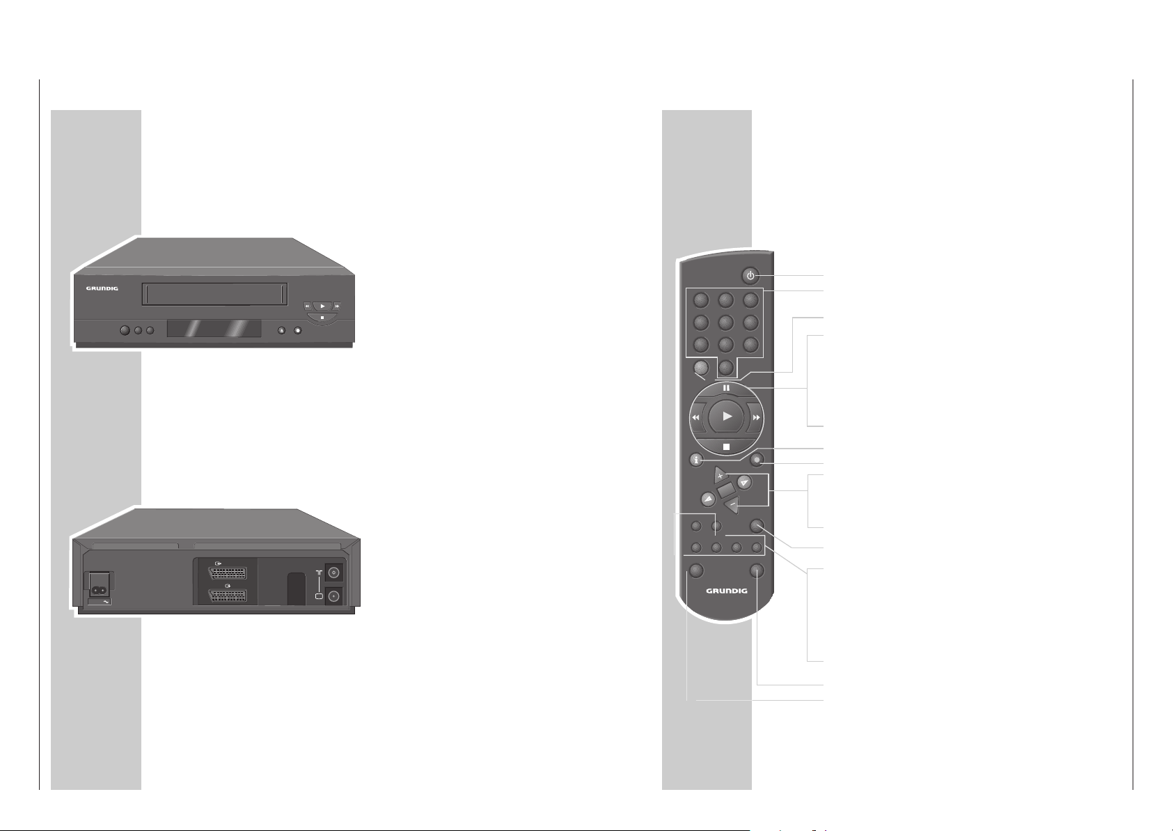
Die Vorderseite des Videorecorders
AUF EINEN BLICK
______________________________________________________
8
o
o
AA
Schaltet den Videorecorder ab.
**
Wählt Programme abwärts.
ÜÜ
Wählt Programme aufwärts.
NN
Schiebt die Cassette aus.
● Startet die Aufnahme.
rr
Bei Wiedergabe: Bildsuchlauf rückwärts;
nach Stopp: Band zurückspulen.
e
Startet die Wiedergabe.
ee
Bei Wiedergabe: Bildsuchlauf vorwärts;
nach Stopp: Band vorspulen.
■ Beendet alle Laufwerkfunktionen.
TV
DECODER/
EURO-AV2
EURO-AV1
AC IN
AC IN~ Netzbuchse für das Netzkabel zur Steckdose.
X EURO-AV1 Euro/AV-Anschluß (zum Fernsehgerät).
DECODER/
Y EURO-AV2 Euro/AV-Anschluß
(zu einem externen Gerät).
ÄÄ
Antennenbuchse (von der Hausantenne).
Ö Antennenbuchse (zum Fernsehgerät).
Die Rückseite des Videorecorders
AUF EINEN BLICK
________________________________________________________________
Die Fernbedienung
Auf dieser Seite finden Sie die wichtigsten Funktionen der Fernbedienung.
Die Bedienung entnehmen Sie bitte dem jeweiligen Kapitel dieser Bedienungsanleitung.
Richten Sie die Fernbedienung auf den Videorecorder.
88
Schaltet den Videorecorder ab (Standby).
1 … 0 Ziffern-Tasten für verschiedene Eingaben,
»0« wählt Programmplatz »
A I
«.
SV Ohne Funktion.
TIMER/V+
II Pause bei Aufnahme, Standbild bei Wiedergabe.
rr Bildsuchlauf rückwärts bei Wiedergabe;
Band rückspulen in „Stopp“.
e
Startet die Wiedergabe.
ee Bildsuchlauf vorwärts bei Wiedergabe;
Band vorspulen in „Stopp“.
■ Beendet alle Laufwerkfunktionen und schaltet den Videorecorder
in „Stopp“.
i INFO Schaltet auf das Menü und zurück auf das Fernsehbild.
● RECORD Startet die Aufnahme.
CC
DD
Wählen Programme, »+« aufwärts, »– « abwärts;
wählen in den Menüs verschiedene Funktionen.
OK Ruft Daten auf, bestätigt und speichert Daten.
FF EE
Zum Feinabstimmen der Programme;
wählen in den Menüs verschiedene Funktionen.
TIMER Aktiviert und deaktiviert die TIMER-Aufnahme.
ON/OFF
SP/LP Ohne Funktion.
CLEAR Löscht Daten, aktiviert Eingaben, setzt die Spielzeitanzeige auf
»
0:00:00
«.
MONITOR Ohne Funktion.
AUDIO Ohne Funktion.
INDEX Aktiviert die INDEX-Suchfunktion.
DUB Aktiviert die Einstellung für den Ausgangskanal des Video-
recorders.
VIDEO 2 Schaltet auf Videobedienebene 2.
TV Schaltet auf die Bedienung eines Fernsehgerätes.
Die Möglichkeiten sind auf Seite 30 beschrieben.
1 2 3
4 5 6
7 8 9
SV 0
TIMER/ V+
INFO RECORD
OK
TIMER
ON/OFF
CLEAR
SP/LP
AUDIOMONITOR INDEX DUB
TV VIDEO 2
Page 6
Allgemeiner Teil / General Section GV 29…, GV 9000…, GV 9300…
1 - 6 GRUNDIG Service
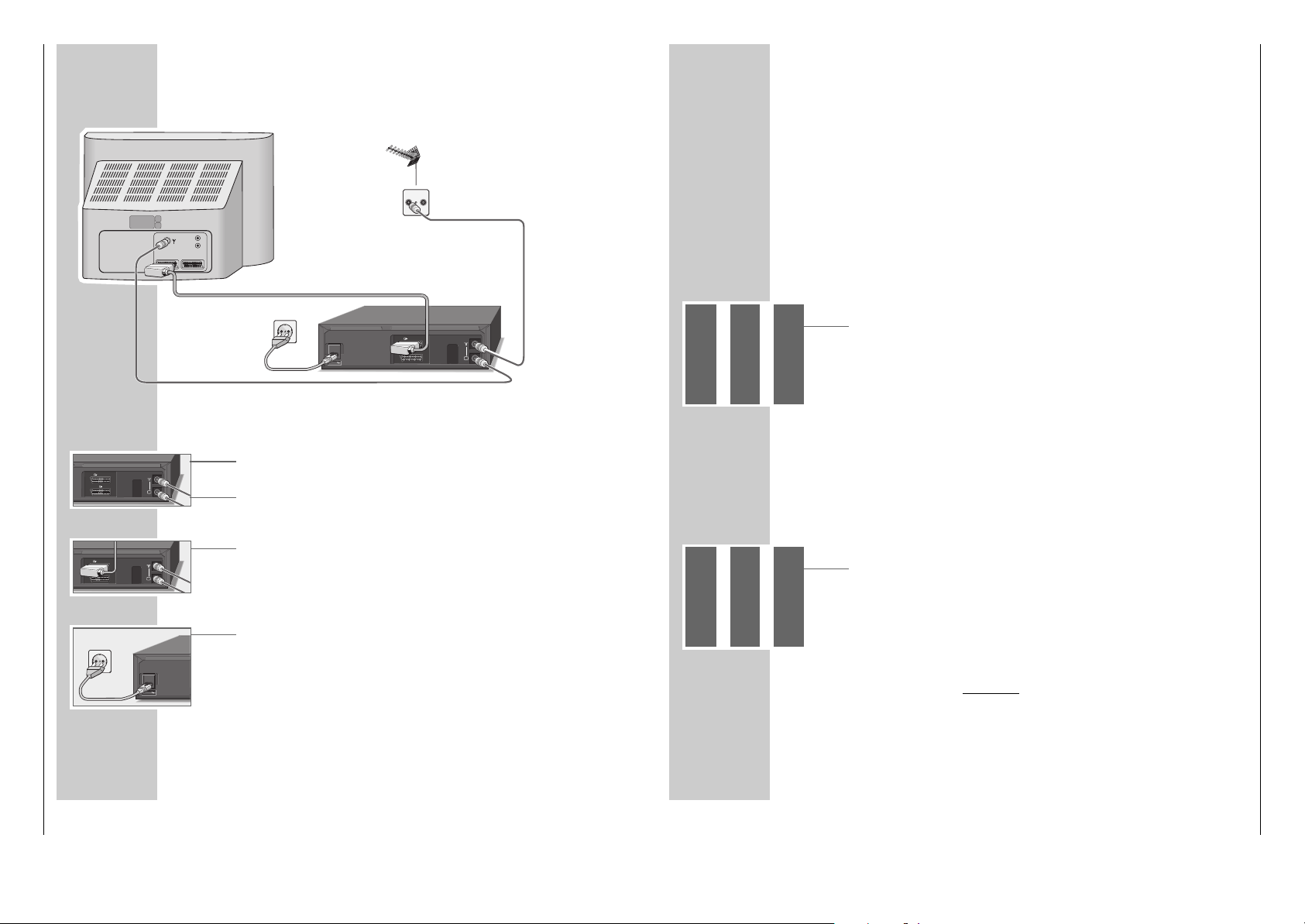
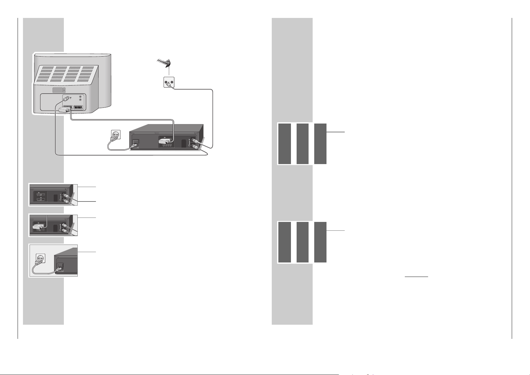
Antenne, Fernsehgerät und Netzkabel anschließen
1 Antennenkabel der Hausantenne in die Antennenbuchse »
ÄÄ
« des Videore-
corders stecken.
2 Beigepacktes Antennenkabel in die Buchse »Ö « des Videorecorders und in
die Antennenbuchse des Fernsehgerätes stecken.
3 Wenn das Fernsehgerät mit einer oder mehreren EURO-AV-Buchsen ausge-
stattet ist:
Handelsübliches EURO-AV-Kabel in die Buchse »XEURO-AV1« des
Videorecorders und in die Buchse AV 1 des Fernsehgerätes stecken.
– Der Vorteil dieses Anschlusses ist eine bessere Bild- und Tonqualität bei
Wiedergabe.
4 Beigepacktes Netzkabel in die Buchse »AC IN~« des Videorecorders
stecken.
Stecker des Netzkabels in die Steckdose stecken.
– Der Videorecorder ist jetzt in Bereitschaft (Standby).
Vorsicht:
Nur durch Ziehen des Netzsteckers ist der Videorecorder vom Stromnetz
getrennt.
ANSCHLIESSEN UND VORBEREITEN
______
1
3
4
TV
DECODER/
EURO-AV2
EURO-AV1
2
EINSTELLUNGEN
_________________________________________________________
Videorecorder und Fernsehgerät anpassen
Diese Einstellung ist nicht notwendig, wenn der Videorecorder und das Fernsehgerät mit einem EURO-AV-Kabel verbunden sind.
Vorbereiten
Fernsehgerät einschalten.
Am Fernsehgerät den Programmplatz »AV« für Recorder-Wiedergabe über das
Antennenkabel wählen.
Nehmen Sie auch die Bedienungsanleitung Ihres Fernsehgerätes zur Hand.
Anpassen
1 Videorecorder mit »
DD
« einschalten.
2 »DUB« ca. 3 Sekunden drücken.
– Anzeige am Videorecorder z.B. »
21 RF
« (21 ist der Ausgangskanal des
Videorecorders).
Der Videorecorder sendet jetzt ein „Testbild“.
3 Am Fernsehgerät im UHF-Bereich, zwischen Kanal 21 und Kanal 69, das
„Testbild“ des Videorecorders suchen (im Beispiel Kanal 21).
4 Einstellung am Fernsehgerät speichern.
5 Einstellung mit »DUB« beenden.
Bildqualität verbessern
Ist die Qualität des „Recorderbildes“ nicht zufriedenstellend oder die Qualität
eines oder mehrerer Fernseh-Programme am Fernsehgerät hat sich verschlechtert,
dann müssen Sie am Fernsehgerät einen anderen „freien“ Kanal suchen.
1 Videorecorder mit »
DD
« einschalten.
2 »DUB« ca. 3 Sekunden drücken.
– Anzeige am Videorecorder z.B. »
21 RF
« (21 ist der Ausgangskanal des
Videorecorders).
Der Videorecorder sendet jetzt ein „Testbild“.
3 Am Fernsehgerät – im UHF-Bereich, zwischen Kanal 21 und 69 – einen Kanal
suchen, der nicht mit einem Fernseh-Programm belegt ist (nur Bildflimmern am
Bildschirm und Tonrauschen).
4 Kanal mit »
** ÜÜ
« am Videorecorder einstellen, bis am Bildschirm des Fernsehgerätes das „Testbild“ erscheint.
Einstellung mit »OK« bestätigen.
5 Kanal am Fernsehgerät speichern.
6 Einstellung mit »DUB« beenden.
TV R
L
R
AV1 AV2
EURO-AV1
DECODER/
AC IN
EURO-AV2
TV
EURO-AV1
DECODER/
EURO-AV2
TV
AC IN
Page 7
GV 29…, GV 9000…, GV 9300… Allgemeiner Teil / General Section
GRUNDIG Service 1 - 7
EINSTELLUNGEN
________________________________________________________________________
5
Suchlauf mit
»OK« starten.
– In der Anzeige am Videorecorder blinkt »AUTO«.
– Der Videorecorder sucht alle Fernsehkanäle nach Fernseh-Programmen ab,
sortiert und speichert sie. Der Suchlauf kann einige Minuten dauern.
– Nach Abschluß des Suchlaufs erscheint am Bildschirm die Meldung
»AUTO-SETUP DURCHGEFÜHRT!« und die Nummer des Ausgangskanal.
In der Anzeige am Videorecorder erscheint »OK«.
Hinweis:
Wenn Videorecorder und Fernsehgerät nicht mit einem EURO-AV-Kabel verbunden sind, müssen Sie die Einstellung auf Seite 11 wiederholen und am
Fernsehgerät den in der Tafel gezeigten Kanal (z.B »
CH 27
«) einstellen.
6 »OK« drücken.
– Am Bildschirm erscheint die Tafel »Uhr«.
Kontrollieren Sie Uhrzeit und Datum.
Hinweis:
Wurde die Uhrzeit nicht automatisch aktualisiert, stellen Sie diese manuell ein,
siehe Kapitel „Uhrzeit und Datum einstellen“ auf Seite 33.
7 Einstellung mit »OK« beenden.
Hinweis:
Weitere Einstellungen – wie die manuelle Suche, die Reihenfolge der FernsehProgramme nachträglich ändern, Fernseh-Programme aus der Sender-Tabelle
löschen oder einem Fernseh-Programm einen Namen geben – sind ab Seite
29 beschrieben.
EINSTELLUNGEN
________________________________________________________________________
Fernseh-Programme einstellen – automatisch
(mit ATS euro plus)
Der Videorecorder hat ein eigenes Empfangsteil. Damit kann er – unabhängig
vom Fernsehgerät – die Fernseh-Programme empfangen und aufzeichnen.
Deshalb müssen Sie die Kanäle der Fernseh-Programme am Videorecorder einstellen.
Bei dieser Einstellung wird automatisch auch die Uhrzeit aktualisiert. Voraussetzung dafür ist, auf Programmplatz 1 des Videorecorders ist ein Fernseh-Programm mit Videotext eingestellt.
Es stehen 88 Programmplätze zur Verfügung, die beliebig mit Fernseh-Programmen von der Antenne oder vom Kabelanschluß belegt werden können.
Vorbereiten
Fernsehgerät einschalten.
Am Fernsehgerät den Programmplatz »AV« für Recorder-Wiedergabe wählen.
Einstellen
1 »
DD
« drücken.
– Am Bildschirm des Fernsehgerätes erscheint die Tafel
»AUTO INSTALLATION«.
Hilfe:
Wenn am Bildschirm die Tafel »AUTO INSTALLATION« nicht erscheint:
»q« und »w« am Videorecorder gleichzeitig drücken, bis die Tafel erscheint.
2 Einstellung mit »OK« beginnen.
– Am Bildschirm erscheint die Tafel »LANGUAGE« (SPRACHE).
3 Sprache mit »
CC DD
FF EE
« wählen und mit »OK« bestätigen.
– Am Bildschirm erscheint die Tafel
»LAND«
.
4 Land (Aufstellungsort) mit »
CC DD
FF EE
« wählen.
Ist in der Tafel das benötigte Land nicht vorhanden, die Zeile
»OTHERS« (SONSTIGE) wählen.
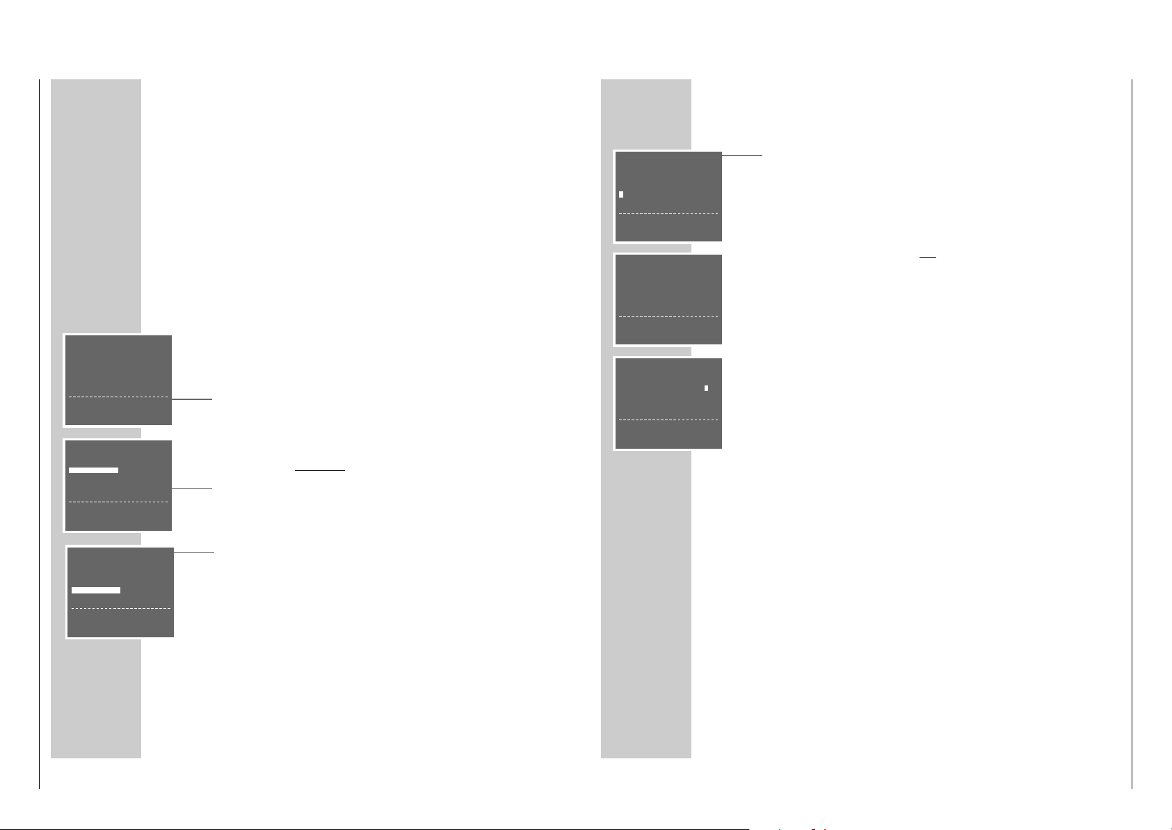
AUTO INSTALLATION
PRESS OK KEY TO START.
AUTOMATISCHE EINSTELLUNG
ZUM START DIE OK TASTE
DRÜCKEN.
OK :ENTER INFO:EXIT
LANGUAGE
ENGLISH DENMARK
DEUTSCH SVENSKA
FRANÇAIS FINLAND
ITALIANO ESPANOL
NEDERLANDS PORTUGUESE
‹›
&& %%
:SELECT
OK :ENTER INFO:EXIT
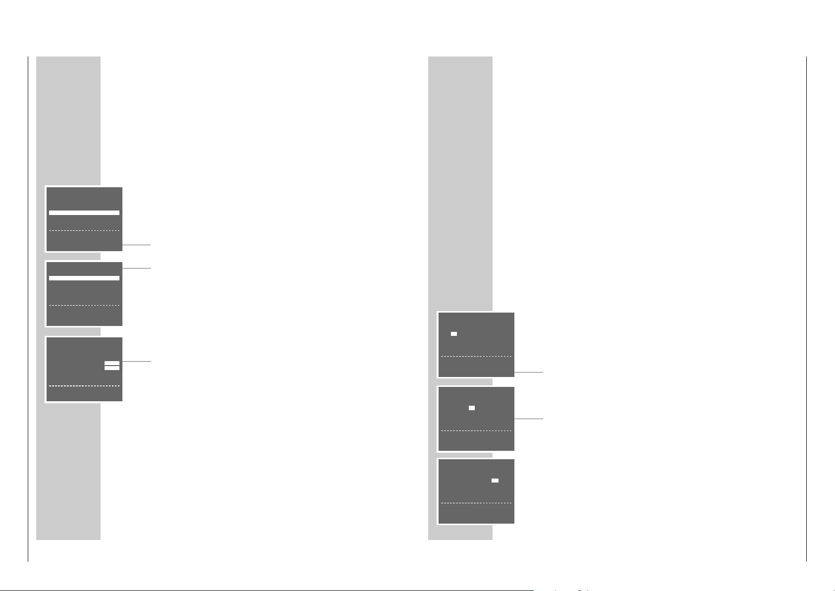
LAND
AI
BN
DK P
FIN E
D S
NL CH
F OTHERS
‹›
&& %%
:WÄHLEN
OK :EINGABE INFO:ENDE
AUTOMATISCHES SORTIEREN.
BITTE WARTEN
. – – – – – – – – – – – – – – – – – –
INFO:ENDE
AUTO-SETUP
DURCHGEFÜHRT!
VCR-AUSGANGSKANAL
WECHSELT AUF CH 27.
OK :EINGABE INFO:ENDE
UHR
ZEIT DATUM JAHR
9:03 05/0299
*
STELLEN *:AUTO - :OFF
‹›
:WÄHLEN
&& %%
:ÄNDERN
OK :EINGABE INFO:ENDE
Page 8

Allgemeiner Teil / General Section GV 29…, GV 9000…, GV 9300…
1 - 8 GRUNDIG Service
SONDEREINSTELLUNGEN
_________________________________
Fernseh-Programme sortieren
Vorbereiten
Fernsehgerät einschalten.
Am Fernsehgerät den Programmplatz »AV« für Recorder-Wiedergabe wählen.
Einstellung
1 Hauptmenü mit »i INFO« aufrufen.
– Am Bildschirm erscheint die Tafel »MENÜ«.
2 Zeile »GRUNDEINSTELLUNG« mit »
CC
« oder »DD« wählen und mit »OK«
aktivieren.
– Am Bildschirm erscheint die Tafel »GRUNDEINSTELLUNG«.
3 Zeile » SENDER SORTIEREN« mit »
CC
« oder »DD« wählen und mit » OK «
aktivieren.
– Am Bildschirm erscheint die Tafel »SENDER SORTIEREN«.
4 Zeile »BEWEGEN« mit »OK« aktivieren.
– Am Bildschirm erscheint die Sendertabelle.
5 Gewünschtes Fernseh-Programm, das getauscht werden soll, mit »
CC DD
FF EE
« wählen und mit »OK« markieren.
6 Programmplatz mit dem das markierte Fernseh-Programm getauscht werden
soll mit »
CC DD
FF EE
« wählen und mit »OK« bestätigen.
Weitere Fernseh-Programme umsortieren, dazu die Pkt. 5 und 6 wiederholen.
7 Einstellung mit »i INFO« beenden.
Fernseh-Programme aus der Sendertabelle löschen
Vorbereiten
Fernsehgerät einschalten.
Am Fernsehgerät den Programmplatz »AV« für Recorder-Wiedergabe wählen.
Einstellung
1 Hauptmenü mit »i INFO« aufrufen.
– Am Bildschirm erscheint die Tafel »MENÜ«.
2 Zeile »GRUNDEINSTELLUNG« mit »
CC
« oder »DD« wählen und mit »OK«
aktivieren.
– Am Bildschirm erscheint die Tafel »GRUNDEINSTELLUNG«.
3 Zeile » SENDER SORTIEREN« mit »
CC
« oder »DD« wählen und mit » OK «
aktivieren.
– Am Bildschirm erscheint die Tafel »SENDER SORTIEREN«.
SENDER SORTIEREN
BEWEGEN
LÖSCHEN
NAME
&& %%
:WÄHLEN
OK :EINGABE INFO:ENDE
BEWEGEN
1ARD 17----- 13----2ZDF 18----- 14----3RTL1 19----- 15----4RTL2 10----- 16----5SAT1 11----- 17-----
SONDEREINSTELLUNGEN
________________________________________________________
4 Zeile »LÖSCHEN« mit »
CC
« oder »DD« wählen und mit »OK« aktivieren.
– Am Bildschirm erscheint die Sendertabelle.
5 Gewünschtes Fernseh-Programm, das gelöscht werden soll, mit »
CC DD
FF EE
« wählen und mit »CLEAR« löschen.
6 Weitere Fernseh-Programme löschen, dazu Pkt.
5
wiederholen.
7 Einstellung mit »i INFO« beenden.
Namen der Fernseh-Programme ändern oder
eingeben
Vorbereiten
Fernsehgerät einschalten.
Am Fernsehgerät den Programmplatz »AV« für Recorder-Wiedergabe wählen.
Einstellung
1 Hauptmenü mit »i INFO« aufrufen.
– Am Bildschirm erscheint die Tafel »MENÜ«.
2 Zeile »GRUNDEINSTELLUNG« mit »
CC
« oder »DD« wählen und mit »OK«
aktivieren.
– Am Bildschirm erscheint die Tafel »GRUNDEINSTELLUNG«.
3 Zeile » SENDER SORTIEREN« mit »
CC
« oder »DD« wählen und mit » OK «
aktivieren.
– Am Bildschirm erscheint die Tafel »SENDER SORTIEREN«.
4 Zeile » NAME« mit »
CC
« oder »DD« wählen und mit » OK « aktivieren.
– Am Bildschirm erscheint die Sendertabelle.
5 Gewünschtes Fernseh-Programm, für das ein Namen eingegeben werden soll,
mit »
CCDD
FF EE
« wählen und mit »OK« bestätigen.
– Die erste Stelle des Namens ist markiert.
6 Zeichen mit »
CC
« oder »DD« eingeben, nächste Stelle mit »
FF
« oder »EE«
wählen und Eingaben für die restlichen Stellen (max. 5 Stellen) wiederholen.
Einstellung mit »OK« speichern.
7 Weitere Namen vergeben, dazu die Pkt.
5
und 6wiederholen.
8 Einstellung mit »i INFO« beenden.
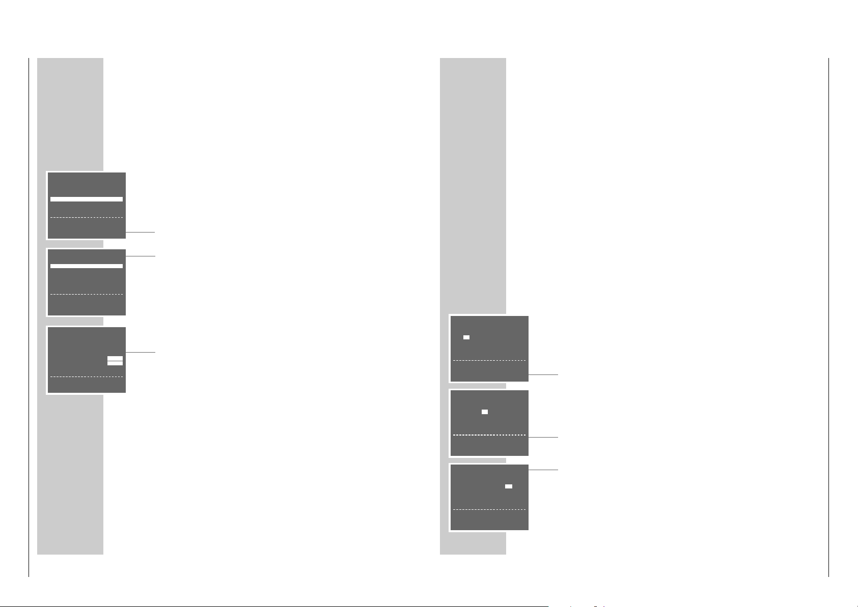
SENDER SORTIEREN
BEWEGEN
LÖSCHEN
NAME
&& %%
:WÄHLEN
OK :EINGABE INFO:ENDE
SENDER SORTIEREN
BEWEGEN
LÖSCHEN
NAME
&& %%
:WÄHLEN
OK :EINGABE INFO:ENDE
NAME
1ARD 17----- 13----2ZDF 18----- 14----3RTL1 19----- 15----4RTL2 10----- 16----5SAT1 11----- 17-----
Page 9
GV 29…, GV 9000…, GV 9300… Allgemeiner Teil / General Section
GRUNDIG Service 1 - 9
Fernseh-Programme einstellen,
durch manuelle Eingabe
Wenn Ihnen die Kanalzahlen/Sonderkanalzahlen der jeweiligen Fernseh-Programme nicht bekannt sind, oder wenn der Recorder ein Fernseh-Programm mit
dem Suchlauf-Speicher-System nicht finden konnte, dann können Sie diese Fernseh-Programme manuell eingeben.
Vorbereiten
Fernsehgerät einschalten.
Am Fernsehgerät den Programmplatz »AV« für Recorder-Wiedergabe wählen.
Einstellung
1 Hauptmenü mit »i INFO« aufrufen.
2 Zeile »GRUNDEINSTELLUNG« mit »
CC
« oder »DD« wählen und mit »OK«
aktivieren.
3 Zeile »SENDEREINSTELLUNG« mit »OK« aktivieren.
– Am Bildschirm erscheint die Tafel zur Sendereinstellung.
Die Zeile »PROGRAMM« ist markiert.
4 Mit »
FF
« oder »EE« den gewünschten Programmplatz wählen, auf dem das
neue Fernseh-Programm gespeichert werden soll.
Hinweis:
Im Hintergrund der Tafel erscheint das aktuelle Fernseh-Programm. Wenn der
Text der Tafel dadurch gestört ist, »DUB« drücken, die Tafel wird blau hinterlegt.
5 Zeile »KANAL« mit »
CC
« oder »DD« wählen.
6 Fernseh-Programm mit »
FF
« oder »EE« einstellen.
7 Fernseh-Programm (wenn nötig) feinabstimmen, dazu mit »
CC
« oder »DD«
die Zeile »FEINABSTIMMUNG« anwählen und mit »FF« oder »EE« verändern.
8 Zeile »AUSLASSEN« mit »
CC
« oder »DD« wählen und mit »EE« »AUS«
wählen.
9 Einstellung für diesen Programmplatz mit »OK« speichern.
Weitere Fernseh-Programme einstellen, dazu die Zeile »PROGRAMM« mit
»CC« oder »DD« wählen und die Pkt. 4 bis 9 wiederholen.
10
Einstellung mit »i INFO« beenden.
SONDEREINSTELLUNGEN
________________________________________________________
GRUNDEINSTELLUNG
SENDEREINSTELLUNG
SENDER SORTIEREN
UHR
SPRACHE
&& %%
:WÄHLEN
OK :EINGABE INFO:ENDE
PROGRAMM ARD 01
➔
KANAL C06
FEINEINSTELLUNG
‹
›
DECODER EIN AUS
AUSLASSEN EIN AUS
&& %%
:WÄHLEN‹›:ÄNDERN
MENÜ
TIMER
MODE
GRUNDEINSTELLUNG
&& %%
:WÄHLEN
OK :EINGABE INFO:ENDE
UHRZEIT UND DA TUM EINSTELLEN
________
Die Digitaluhr des Videorecorders läuft ca. 1 Stunde weiter, auch wenn der
Videorecorder vom Stromnetz getrennt ist.
Die Uhrzeit ist in der Anzeige jedoch nicht sichtbar.
Uhrzeit und Datum automatisch aktualisieren
Wenn auf Programmplatz 1 des Videorecorders ein Fernseh-Programm mit
Videotext eingestellt ist, dann aktualisiert der Videorecorder damit seine „interne“
Uhr.
Diese Aktualisierung wird regelmäßig an Sonntagen zwischen 3 Uhr und 6 Uhr
durchgeführt, dadurch erkennt der Videorecorder auch die Sommer-/Winterzeitumstellung.
Zum Aktualisieren von Uhrzeit und Datum Videorecorder mit »88« abschalten
(Standby-Betrieb).
Uhrzeit und Datum manuell einstellen
Vorbereiten
Fernsehgerät einschalten.
Am Fernsehgerät den Programmplatz »AV« für Recorder-Wiedergabe wählen.
Videorecorder mit »DD« einschalten.
Einstellung
1 Hauptmenü mit »i INFO« aufrufen.
2 Zeile »GRUNDEINSTELLUNG« mit »
CC
« oder »DD« wählen und mit »OK«
aktivieren.
3 Zeile »UHR« mit »
CC
« oder »DD« wählen und mit »OK« aktivieren.
– Am Bildschirm erscheint die Tafel »UHR«, die Anzeige »ZEIT« ist markiert.
4 Mit »
CC
« oder »DD« die Stunden eingeben, danach »EE« drücken und mit
»CC« oder »DD« die Minuten eingeben.
5 Zeile »DATUM« mit »
EE
« wählen und mit »CC« oder »DD« den Tag einge-
ben, danach »EE« drücken und mit »CC« oder »DD« den Monat eingeben.
6 Zeile »JAHR« mit »
EE
« wählen und mit »CC« oder »DD« eingeben.
Hinweis:
– Die Anzeige »*« bedeutet Automatische Aktualisierung der Uhrzeit an.
Zum Abschalten dieser Funktion die Anzeige »*« mit »EE« wählen und mit
»CC« oder »DD« abschalten.
7 Einstellung mit »OK« beenden.
UHR
ZEIT DATUM JAHR
12:–– – –/– – ––
*
ZEIT:24HR ANZEIGE
‹›
:WÄHLEN
&& %%
:ÄNDERN
INFO:ENDE
UHR
ZEIT DATUM JAHR
12:00 10/5 99
*
‹›
:WÄHLEN
&& %%
:ÄNDERN
OK :EINGABE INFO:ENDE
UHR
ZEIT DATUM JAHR
12:00 10 /–– ––
*
DATUM: TAG
‹›
:WÄHLEN
&& %%
:ÄNDERN
INFO:ENDE
Page 10

Allgemeiner Teil / General Section GV 29…, GV 9000…, GV 9300…
1 - 10 GRUNDIG Service
BESONDERHEITEN
____________________________________________________
Die Funktionen „Bildschirmanzeigen aus- oder einblenden“, „Ausschalt-Automatik aktivieren“, „NTSC-Wiedergabe“, „DECODER-EURO-AV2-Buchsen für externe Geräte anpassen“, „Kindersicherung“ und „Bedienebene des Videorecorders
wählen“ können Sie aus dem Menü »MODE« wählen.
Menü »MODE« wählen
1 Fernsehgerät einschalten.
2 Am Fernsehgerät den Programmplatz »AV« für Recorder-Wiedergabe
wählen.
3 Videorecorder mit »
DD
« einschalten.
4 Hauptmenü mit »i INFO« aufrufen.
– Am Bildschirm erscheint die Tafel »MENÜ«.
5 Zeile »MODE« mit »
CC
« oder »DD« wählen und mit »OK« aktivieren.
– Am Bildschirm erscheint die Tafel »MODE«.
6 Wählen Sie aus der Tafel »MODE« die gewünschte Funktion, die weitere
Bedienung entnehmen Sie bitte den folgenden Kapiteln, jeweils ab Pkt. 1.
Bildschirmanzeigen aus- oder einblenden
(OSD – On Screen Display)
1 Zeile »OSD MODE« mit »
CC
« oder »DD« wählen.
2 »AUS« mit »
EE
« oder »AUTO« mit »FF« wählen und mit »OK«
bestätigen.
Ausschaltautomatik aktivieren
Ist die Abschaltautomatik aktiviert, schaltet der Videorecorder nach 2- oder 6
Stunden automatisch ab.
1 Zeile »ABSCHALTEN« mit »
CC
« oder »DD« wählen.
2
» AUS«, »2 HR« oder » 6 HR« mit »FF« oder »EE« wählen und mit » OK«
bestätigen.
NTSC-Wiedergabe
Mit dieser Einstellung wählen Sie die Farbnorm der Cassettenwiedergabe für das
angeschlossene Fernsehgerät an Buchse »X EURO-AV1«. Wählen Sie die
Einstellung PAL-TV für ein PAL-Fernsehgerät oder die Einstellung NTSC 443 für
ein Multinorm-Fernsehgerät.
1 Zeile »NTSC PB« mit »
CC
« oder »DD« wählen.
2
» PAL-TV« mit »FF« oder » NTSC 443 (= Multinorm)« mit »EE« wählen und mit
»OK« bestätigen.
MODE
➔
OSD-MODE AUTO AUS
ABSCHALTEN AUS 2HR 6HR
NTSC PB PAL-TV NTSC443
AV-2 AV-IN DECODER
SPERRE EIN11 AUS
VCR NO. 1 2
&& %%
:WÄHLEN‹›:ÄNDERN
OK :EINGABE INFO:ENDE
MODE
➔
OSD-MODE AUTO AUS
ABSCHALTEN AUS 2HR 6HR
NTSC PB PAL-TV NTSC443
AV-2 AV-IN DECODER
SPERRE EIN11 AUS
VCR NO. 1 2
&& %%
:WÄHLEN‹›:ÄNDERN
OK :EINGABE INFO:ENDE
MODE
OSD-MODE AUTO AUS
➔
ABSCHALTEN AUS 2HR 6HR
NTSC PB PAL-TV NTSC443
AV-2 AV-IN DECODER
SPERRE EIN11 AUS
VCR NO. 1 2
&& %%
:WÄHLEN‹›:ÄNDERN
OK :EINGABE INFO:ENDE
MODE
OSD-MODE AUTO AUS
ABSCHALTEN AUS 2HR 6HR
➔
NTSC PB PAL-TV NTSC443
AV-2 AV-IN DECODER
SPERRE EIN11 AUS
VCR NO. 1 2
&& %%
:WÄHLEN‹›:ÄNDERN
OK :EINGABE INFO:ENDE
BESONDERHEITEN
_____________________________________________________________________
DECODER/EURO-AV2-Buchse für externe Geräte
anpassen
Mit dieser Einstellung passen Sie die DECODER/EURO-AV2-Buchse an das extere Gerät an. Einstellung AV-IN benötigen Sie für einen zweiten Videorecorder
oder einen Satellitenreceiver, Einstellung DECODER benötigen Sie für einen PAYTV-Decoder.
1 Zeile »AV-2« mit »
CC
« oder »DD« wählen.
2
»AV-IN« mit »FF« oder »DECODER« mit »EE« wählen und mit »OK« bestätigen.
Kindersicherung
Mit der Kindersicherung können Sie alle Funktionen des Videorecorders
verriegeln.
1 Zeile »SPERRE« mit »
CC
« oder »DD« wählen.
2
»EIN« mit »FF« wählen und mit »OK« bestätigen.
– Der Bildschirm des Fernsehgerätes wird blau.
3 Kindersicherung aufheben, dazu Einstellung wiederholen und in Pkt. 2
»AUS«
mit »EE« wählen.
Bedienebene des Videorecorders wählen
Mit dieser Fernbedienung können verschiedene GRUNDIG Videorecorder unabhängig voneinander bedient werden.
Fragen Sie Ihren Fachhändler, welche GRUNDIG Videorecorder hierfür geeignet
sind.
Damit sich beide Videorecorder nicht gegenseitig stören, muß die Bedienebene
des GV 9300 umgestellt werden.
1 Zeile »VCR NO.« mit »
CC
« oder »DD« wählen.
2 »2« mit »
EE
« (oder »1« mit »FF«) wählen und mit »OK« bestätigen.
– Der GV 9300 ist auf Bedienebene 2 eingestellt. Für die Bedienung des
GV 9300 muß jetzt »VIDEO 2« gedrückt und gehalten werden und dabei
die jeweils benötigte Taste gedrückt werden.
Dauerlauf-Wiedergabe
Ist diese Funktion eingeschaltet, spult der Videorecorder am Ende des Videobandes die Cassette automatisch zurück und beginnt erneut mit der Wiedergabe.
1 Wiedergabe mit »e« starten.
2 »e« am Videorecorder drücken und halten und gleichzeitig » rr« am
Videorecorder drücken.
3 Dauerlauf-Wiedergabe mit »■ « beenden.
MODE
OSD-MODE AUTO AUS
ABSCHALTEN AUS 2HR 6HR
NTSC PB PAL-TV NTSC443
AV-2 AV-IN DECODER
➔
SPERRE EIN11 AUS
VCR NO. 1 2
&& %%
:WÄHLEN‹›:ÄNDERN
OK :EINGABE INFO:ENDE
MODE
OSD-MODE AUTO AUS
ABSCHALTEN AUS 2HR 6HR
NTSC PB PAL-TV NTSC443
AV-2 AV-IN DECODER
SPERRE EIN11 AUS
➔
VCR NO. 1 2
&& %%
:WÄHLEN‹›:ÄNDERN
OK :EINGABE INFO:ENDE
MODE
OSD-MODE AUTO AUS
ABSCHALTEN AUS 2HR 6HR
NTSC PB PAL-TV NTSC443
➔
AV-2 AV-IN DECODER
SPERRE EIN11 AUS
VCR NO. 1 2
&& %%
:WÄHLEN‹›:ÄNDERN
OK :EINGABE INFO:ENDE
Page 11

GV 29…, GV 9000…, GV 9300… Allgemeiner Teil / General Section
GRUNDIG Service 1 - 11
Operating Hints This chapter contains excerpts from the operating instructions. For further particulars please refer to the appropriate user manuals the part numbers of which are indicated in the
relevant spare parts lists.
Front side of the video recorder
A T A GLANCE
_________________________________________________________________
Rear side of the video recorder
AA
Switches the video recorder off.
**
Selects programmes downwards.
ÜÜ
Selects programmes upwards.
NN
Ejects the cassette.
● Starts recording.
rr
During playback: reverse picture search;
after stop: fast rewind.
e
Starts playback.
ee
During playback: forward picture search;
after stop: fast forward wind.
■ Ends all drive mechanism functions.
AC IN~ Socket for mains cable to mains supply socket.
X EURO-AV1 Euro/AV connector (for TV set).
DECODER
Y EURO-AV2 Euro/AV connector (for external device).
ÄÄ
Aerial socket (for domestic aerial).
Ö Aerial socket (for TV set).
AT A GLANCE
______________________________________________________________________
The remote control
On this page you will find a brief description of the important remote control
functions. Refer to the corresponding chapters of this manual for more information on operation.
Direct the remote control at the video recorder.
88
Switches the video recorder off (standby).
1 … 0 Numeric buttons for various entries ,
the »0« button selects the »
A I
« programme position.
SV Initiates programmed recording with ShowView.
TIMER/V+
II Pause in recording mode, freeze-frame in playback mode.
rr Reverse picture search during playback,
fast rewind after stop.
e
Starts playback.
ee Forward picture search during playback,
fast forward after stop.
■ Ends all drive mechanism functions and switches the vidoe
rocorder to “stop”.
i INFO Switches to the menu and back to the TV picture.
● RECORD Starts recording.
CC
DD
Select channels, »+« up, »– « down;
select various functions in the menus.
OK Calls up, confirms and stores data.
FF EE
Finetuning;
select various functions in the menus.
TIMER Activates and de-activates programmed recording.
ON/OFF
SP/LP Switches between longplay mode and standard play mode.
CLEAR Clears data, activates entries, resets the playing time display to
»
0:00:00
«.
MONITOR Switches the picture screen between TV picture and video recor-
der picture (monitor mode).
AUDIO No function.
INDEX Activates the INDEX search function.
DUB Activates the setting for the output channel of the video recorder.
VIDEO 2 Switches to the video control address 2.
TV Swiches to TV control mode.
See page 37 for the possible functions.
AC IN
o
o
8
DECODER/
EURO-AV1
EURO-AV2
TV
1 2 3
4 5 6
7 8 9
SV 0
TIMER/ V+
INFO RECORD
OK
TIMER
ON/OFF
CLEAR
SP/LP
AUDIOMONITOR INDEX DUB
TV VIDEO 2
Page 12
Allgemeiner Teil / General Section GV 29…, GV 9000…, GV 9300…
1 - 12 GRUNDIG Service
Connecting the aerial, TV set and mains cable
1 Connect the aerial cable from the domestic aerial with the aerial socket
»ÄÄ« of the video recorder.
2 Connect the aerial cable supplied with the »Ö « socket of the video recorder
and the aerial socket of the TV set.
3 If the TV set is equipped with one or several EURO-AV sockets:
connect the »XEURO-AV1« socket of the video recorder with the AV 1
socket of the TV set using a commercially available EURO-AV cable.
– The advantage of this connection is a better picture and sound quality
during playback.
4 Connect the mains cable supplied with the »AC IN ~« socket of the video
recorder.
Connect the mains cable with the mains supply socket.
– The video recorder is now in standby.
Attention:
The video recorder is isolated from the mains only when the mains cable is
disconnected from the mains supply socket.
CONNECTING AND PREPARATION
________
1
3
4
2
SETTINGS
____________________________________________________________________________
Adjusting the TV set to the video recorder
This adjustment is not necessary if the video recorder and the TV set are
connected with a EURO-AV cable.
Preparation
Switch the TV set on.
On the TV set, select the »AV« programme position for video playback via the
aerial socket.
Consult also the user manual of your TV set.
Adjustment
1 Switch the video recorder on using the »
DD
« button.
2 Press the »DUB« button for about 3 seconds.
– »
21 RF
«, for example, is displayed on the video recorder (21 is the output
channel of the video recorder).
The video recorder now emits a test pattern.
3 Search the test pattern on the TV set in the UHF range on a channel between
21 and 69 (channel 21 in the example).
4 Store the setting on the TV set.
5 Press the »DUB« button to end the setting.
Improving the picture quality
If the quality of the “recorder picture” is poor, or the picture quality of one or
more TV programmes on the TV set gets worse, you must search a different “free”
channel on the TV set.
1 Switch the video recorder on using the »
DD
« button.
2 Press the »DUB« button for about 3 seconds.
– »
21 RF
«, for example, is displayed on the video recorder (21 is the output
channel of the video recorder).
The video recorder now emits a test pattern.
3 On the TV set in the UHF range between channel 21 and channel 69, search
for a “free“ channel on which no TV programme is received (only snow and
sound noise).
4 Use the »
** ÜÜ
« buttons on the video recorder to change the output channel
of the video recorder until the test pattern appears on the picture screen of the
TV set.
Press the »OK« button to store the setting.
5 Store the channel on the TV set.
6 Press the »DUB« button to end the setting.
TV R
L
R
AV1 AV2
EURO-AV1
DECODER/
AC IN
EURO-AV2
TV
EURO-AV1
DECODER/
EURO-AV2
TV
EURO-AV1
DECODER/
EURO-AV2
TV
AC IN
Page 13

GV 29…, GV 9000…, GV 9300… Allgemeiner Teil / General Section
GRUNDIG Service 1 - 13
SETTINGS
____________________________________________________________________________________
5 Press the »OK« button.
– The »CLOCK« table appears on the picture screen.
Check the time and the date.
Note:
If the time has not been updated automatically, it must be set manually, see
chapter “Setting the Time and Date” on page 34.
6 Press the »OK« button to end the setting.
Note:
Further settings such as manual channel search, changing the order of the
channels at a later date, clearing TV channels from the station table, or
assigning station names, are described from page 30 on.
SETTINGS
____________________________________________________________________________________
Channel programming with the automatic tuning
system ATS euro plus
The recorder has a built-in receiver. It can therefore receive and record television
programmes independently of the TV set.
For this, you must programme the TV channels on the video recorder.
When carrying out this function, the time is automatically updated, provided a TV
programme with teletext is received on programme position 1.
88 programme positions are available which can be assigned as desired to TV
channels received via the aerial or the cable system.
Preparation
Switch the TV set on.
Select the »AV« programme position for video playback on the TV set.
Programming
1 Press the »
DD
« button.
– The »AUTO INSTALLATION« table appears on the picture screen of the
TV set.
Help:
If the »AUTO INSTALLATION« table does not appear, press the»q« and »w«
buttons on the video recorder at the same time until the table appears.
2 Initiate programming with the »OK« button.
– The »LANGUAGE« table appears on the picture screen.
3 Use the »
CC DD
FF EE
« buttons to select the desired language.
4
Press the
»OK« button to start the automatic tuning system.
– »AUTO« flashes in the video recorder’s display.
– The recorder searches all channel numbers for TV stations, then sorts and
stores them. This can take several minutes.
– When the search is completed, the message »AUTO-SETUP COMPLETED!«
and the number of the output channel appear on the picture screen.
»OK« appears in the video recorder’s display.
Note:
If the video recorder and the TV set are not connected with a EURO-AV cable,
you must repeat the setting on page 11 and tune the TV set to the channel
(e.g.»
CH 27
«) indicated in the table.
AUTO INSTALLATION
PRESS OK KEY TO START.
AUTOMATISCHE EINSTELLUNG
ZUM START DIE OK TASTE
DRÜCKEN.
OK :ENTER INFO:EXIT
LANGUAGE
ENGLISH DENMARK
DEUTSCH SVENSKA
FRANÇAIS FINLAND
ITALIANO ESPANOL
NEDERLANDS PORTUGUESE
‹›
&& %%
:SELECT
OK :ENTER INFO:EXIT
CLOCK
TIME DATE YEAR
9:03 05/0299
*
ADJUST *:AUTO - :OFF
‹›
:SELECT
&& %%
:CHANGE
OK :ENTER INFO:EXIT
AUTO-SETUP COMPLETED!
VCR OUTPUT CHANNEL
WILL CHANGE TO CH 27.
OK :ENTER INFO:EXIT
AUTOMATIC SORTING
PLEASE WAIT
. – – – – – – – – – – – – – – – – – –
INFO:EXIT
Page 14

Allgemeiner Teil / General Section GV 29…, GV 9000…, GV 9300…
1 - 14 GRUNDIG Service
SPECIAL SETTINGS
_____________________________________________________________________
4 Select the »CANCEL« line using the »
CC
« or »DD« button then activate it with
the »OK« button.
– The station table appears on the picture screen.
5 Select the channel to be cleared using the »
CC DD
FF EE
« buttons then clear
it with the »CLEAR« button.
6 To clear further channels, repeat the step
5
.
7 Press the »i INFO« button to end the setting.
Changing or entering station names
Preparation
Switch the TV set on.
Select the »AV« programme position for video playback on the TV set.
Setting
1 Call up the main menu with the »i INFO« button.
– The »MENU« table appears on the picture screen.
2 Select the » INSTALLATION« line using the »
CC
« or »DD« button then activate it with the »OK« button.
– The »INSTALLATION« table appears on the picture screen.
3 Select the » CHANNEL SORT « line using the »
CC
« or »DD« button then
activate it with the »OK« button.
– The »CHANNEL SORT« table appears on the picture screen.
4 Select the »NAME« line using the »
CC
« or »DD« button then activate it with
the »OK« button.
– The station table appears on the picture screen.
5 Use the »
CC DD
FF EE
« buttons to select the channel for which you wish to
enter a name then confirm with the »OK« button.
– The first position of the name is marked.
6 Use the »
CC
« or »DD« button to enter the desired character, use the »
FF
«
or »EE« button to select the next position, then repeat these steps for the
remaining positions (max. 5 positions).
Store the setting with the »OK« button.
7 To assign further names repeat the steps
5
and 6.
8 Press the »i INFO« button to end the setting.
CHANNEL SORT
MOVE
CANCEL
NAME
&& %%
:SELECT
OK :ENTER INFO:EXIT
CHANNEL SORT
MOVE
CANCEL
NAME
&& %%
:SELECT
OK :ENTER INFO:EXIT
NAME
1ARD 17----- 13----2ZDF 18----- 14----3RTL1 19----- 15----4RTL2 10----- 16----5SAT1 11----- 17-----
SPECIAL SETTINGS
____________________________________________________
Re-sorting TV channels
Preparation
Switch the TV set on.
Select the »AV« programme position for video playback on the TV set.
Setting
1 Call up the main menu with the »i INFO« button.
– The »MENU« table appears on the picture screen.
2 Select the »INSTALLATION « line using the »
CC
« or »DD« button then activate it with the »OK« button.
– The »INSTALLATION « table appears on the picture screen.
3 Select the » CHANNEL SORT« line using the »
CC
« or »DD« button then
activate it with the »OK« button.
– The »CHANNEL SORT« table appears on the picture screen.
4 Activate the »MOVE« line with the »OK« button.
– The station table apears on the picture screen.
5 Use the »
CC DD
FF EE
« buttons to select the channel to be moved then mark it
with the »OK« button.
6 Select the programme position to be exchanged with the marked position
using the »
CC DD
FF EE
« buttons then confirm with the »OK« button.
To re-sort further programme positions, repeat the steps 5 and 6
7 Press the »i INFO« button to end the setting.
Clearing TV channels from the station table
Preparation
Switch the TV set on.
Select the »AV« programme position for video playback on the TV set.
Setting
1 Call up the main menu with the »i INFO« button.
– The »MENU« table appears on the picture screen.
2 Select the »INSTALLATION « line using the »
CC
« or »DD« button then activate it with the »OK« button.
– The »INSTALLATION « table appears on the picture screen.
3 Select the » CHANNEL SORT« line using the »
CC
« or »DD« button then
activate it with the »OK« button.
– The »CHANNEL SORT« table appears on the picture screen.
CHANNEL SORT
MOVE
CANCEL
NAME
&& %%
:SELECT
OK :ENTER INFO:EXIT
MOVE
1ARD 17----- 13----2ZDF 18----- 14----3RTL1 19----- 15----4RTL2 10----- 16----5SAT1 11----- 17-----
Page 15
GV 29…, GV 9000…, GV 9300… Allgemeiner Teil / General Section
GRUNDIG Service 1 - 15
Manual channel programming
If you know the channel/special channel numbers of the TV stations you wish to
programme, or if the recorder could not find a TV station with the help of the
automatic tuning system, you can programme the channels manually.
Preparation
Switch the TV set on.
Select the »AV« programme position for video playback on the TV set.
Setting
1 Call up the main menu with the »i INFO« button.
2 Select the » INSTALLATION « line using the »
CC
« or »DD« button then acti-
vate it with the »OK« button.
3 Activate the »CHANNEL PRESET« line with the »OK« button.
– The table for channel programming appears on the picture screen.
The »PRESET« line is marked.
4 Use the »
FF
« or »EE« button to select the programme position on which the
new TV channel is to be stored.
Note:
The current TV programme appears in the background of the station table. If
this disturbs you, press the »DUB« button to get a blue background instead of
the TV picture.
5 Select the »SYSTEM« line using the »
CC
« or »DD« button then select the TV
system required: »B/G« with the »FF«,´button, »D/K« with the »EE«
button.
6 Select the »CHANNEL« line using the »
CC
« or »DD« button.
7 Select the desired channel using the »
FF
« or »EE« button.
8 If finetuning is required, select the » FINETUNING« line with the »
CC
« or
»DD« button then use the »FF« or »EE« button for finetuning.
9 Select the »SKIP« line using the »
CC
« or »DD« button then use the »EE«
button to select »OFF«.
10Store the setting for this programme position with the »OK« button.
To programme further channels, select the »PRESET« line using the »CC« or
»DD« button then repeat the steps 4 to 10.
11
Press the »i INFO« button to end the setting.
SPECIAL SETTINGS
_____________________________________________________________________
INSTALLATION
CHANNEL PRESET
CHANNEL SORT
CLOCK
LANGUAGE
&& %%
:SELECT
OK :ENTER INFO:EXIT
PRESET ARD 01
➔
SYSTEM B/G D/K
CHANNEL C06
FINE TUNING
‹
›
DECODER ON OFF
SKIP ON OFF
&& %%
:SELECT
‹›
:CHANGE
MENU
TIMER
MODE
INSTALLATION
&& %%
:SELECT
OK :ENTER INFO:EXIT
SETTING THE TIME AND DA TE
______________________
The digital clock of the recorder continues running for approximately 1 hour even
when the recorder is disconnected from the mains.
However, the time is not visible in the display
Automatic updating
If a TV channel which has Teletext is set on programme position 1 of the recorder,
the recorder updates automatically its internal clock.
This updating is regularly carried out every Sunday between 3 and 6 hours a.m.
This also means that the recorder will recognize the change from summer to
winter time.
For updating the time and date, switch the video recorder off using the »88«
button (standby mode).
Manual setting
Preparation
Switch the TV set on.
Select the »AV« programme position for video playback on the TV set.
Switch the video recorder on using the »DD« button.
Setting
1 Call up the main menu with the »i INFO« button.
2 Select the » INSTALLATION« line using the »
CC
« or »DD« button then acti-
vate it using the »OK« button.
3 Select the »CLOCK« line with the »
CC
« or »DD« button then activate it with
the »OK « button.
– The »CLOCK« table appears on the picture screen, the »TIME« item is
marked.
4 Use the »
CC
« or »DD« button to enter the hours, then press the »EE« button
and enter the minutes with the »CC« or »DD« button.
5 Select »DATE« with the »
EE
« button, enter the day with the »CC« or »DD«
button, then press the »EE« button and enter the month with the »CC« or
»DD« button.
6 Select » YEAR« with the »
EE
« button then enter the year with the »CC« or
»DD« button.
Note:
– The »*« sign signals automatic updating of the clock. To switch this function
off, select the »*« sign with the »EE« button then use the »CC« or »DD«
button to switch it off.
7 Store the setting with the »OK« button.
CLOCK
TIME DATE YEAR
12:–– – –/– – ––
*
TIME:24HR INDICATION
‹›
:SELECT
&& %%
:CHANGE
INFO:EXIT
CLOCK
TIME DATE YEAR
12:00 10/5 99
*
‹›
:SELECT
&& %%
:CHANGE
OK :ENTER INFO:EXIT
CLOCK
TIME DATE YEAR
12:00 10 /–– ––
*
DATE : DAY
‹›
:SELECT
&& %%
:CHANGE
INFO:EXIT
Page 16

Allgemeiner Teil / General Section GV 29…, GV 9000…, GV 9300…
1 - 16 GRUNDIG Service
SPECIAL FUNCTIONS
________________________________________________________________
Adjusting the DECODER/EURO-AV2 socket for external
devices
With this function you can adjust the DECODER/EURO-AV2 socket to an external
device. The AV-IN setting is required for a second video recorder or a satellite
receiver, the DECODER setting is required for a PAY-TV decoder.
1 Select the »AV-2« line with the »
CC
« or »DD« button.
2 Select »AV-IN« with the »
FF
« button, or »DECODER« with the »EE« button,
then confirm with the »OK« button.
Child lock
The child lock allows you to lock all functions of the video recorder.
1 Select the »LOCK« line with the »
CC
« or »DD« button.
2 Select »ON« with the »
FF
« button then confirm with the »OK« button.
– The picture screen of the TV set turns blue.
3 To de-activate the child lock, repeat the setting but select » OFF« in step 2
using the »EE« button.
Selecting the video recorder’s control address
Your remote control can be used to operate different GRUNDIG video recorders
independently of one another.
Ask your specialized dealer which GRUNDIG video recorders are suited.
To ensure that the two video recorders do not disturb each other, the control
address of the GV 9300 must be changed.
1 Select the »VCR NO.« line with the »
CC
« or »DD« button.
2 Select »2« with the »
EE
« button (or »1« with the »FF« button) then confirm
with the »OK« button.
– When selecting 2, the GV 9300 is set to the remote control address 2. In
order to control the GV 9300 you now must press and hold down the
»VIDEO 2« button while pressing the desired function button.
Selecting the sound system
With this function you select the sound system for adjusting the video recorder to
the TV set.
1 Select the »RF-SYSTEM« line using the »
CC
« or »DD« button.
2 Select » B/G« with the »
FF
« button or » D/K« with the »EE« button then
confirm with the »OK« button.
MODE
OSD-MODE AUTO OFF
OFF POWER OFF 2HR 6HR
NTSC PB PAL-TV NTSC443
AV-2 AV-IN DECODER
➔
CHILD LOCK ON11 OFF
VCR NO. 1 2
RF-SYSTEM B/G D/K
&& %%
:SELECT
‹›
:CHANGE
OK :ENTER INFO:EXIT
MODE
OSD-MODE AUTO OFF
OFF POWER OFF 2HR 6HR
NTSC PB PAL-TV NTSC443
AV-2 AV-IN DECODER
CHILD LOCK ON11 OFF
➔
VCR NO. 1 2
RF-SYSTEM B/G D/K
&& %%
:SELECT
‹›
:CHANGE
OK :ENTER INFO:EXIT
MODE
OSD-MODE AUTO OFF
OFF POWER OFF 2HR 6HR
NTSC PB PAL-TV NTSC443
➔
AV-2 AV-IN DECODER
CHILD LOCK ON11 OFF
VCR NO. 1 2
RF-SYSTEM B/G D/K
&& %%
:SELECT
‹›
:CHANGE
OK :ENTER INFO:EXIT
MODE
OSD-MODE AUTO OFF
OFF POWER OFF 2HR 6HR
NTSC PB PAL-TV NTSC443
AV-2 AV-IN DECODER
CHILD LOCK ON11 OFF
VCR NO. 1 2
➔
RF-SYSTEM B/G D/K
&& %%
:SELECT
‹›
:CHANGE
OK :ENTER INFO:EXIT
OPERA TION WITH A DECODER
__________________
If you wish to receive encrypted TV programmes from private broadcasters with
your video recorder, you will require an appropriate decoder.
Ask your specialized dealer which decoder is appropriate.
Connection
Connect the »DECODER/Y EURO-AV2« socket on the video recorder with
the corresponding socket on the decoder using a EURO-AV cable.
Preparation
Switch the TV set on.
Select the »AV« programme position for video playback on the TV set.
Adjusting a programme position for a decoder
1 Call up the main menu using the »i INFO« button.
2 Select the »MODE« line using the »
CC
« or »DD« button then activate it with
the »OK« button.
3 Select the » AV -2« line using the »
CC
« or »DD« button then use the »QQ«
button to select the »DECODER« setting.
4 Store the setting with the »OK« button.
5 Call up the main menu using the »i INFO« button.
6 Select the » INSTALLATION « line using the »
CC
« or »DD« button then acti-
vate it with the »OK« button.
7 Activate the »CHANNEL PRESET« line with the »OK« button.
– The table for station programming appears on the picture screen. The
»PRESET« line is marked.
8 Use the »
FF
« or »EE« button to select the programme position on which the
encrypted programme is received via the decoder.
9 Select the » DECODER« line using the »
CC
« or »DD« button then use the
»FF« button to select »ON«.
10
Store the setting for this programme position with the »OK« button.
11
End the setting with the »i INFO« button.
Recording a PAY-TV programme
1 Switch the TV set on. Select the »AV« programme position for video playback
on the TV set.
2 Select the programme position for the PAY-TV programme using the »
CC DD
«
or »
** ÜÜ
«or »0…9« buttons.
3 Press the »● RECORD« button a longer time to start recording.
– The PAY-TV programme is recorded.
MENU
TIMER
MODE
INSTALLATION
&& %%
:SELECT
OK :ENTER INFO:EXIT
➔
PRESET ARD 01
SYSTEM B/G D/K
CHANNEL C06
FINE TUNING
‹
›
DECODER ON OFF
SKIP ON OFF
&& %%
:SELECT
‹›
:CHANGE
PRESET ARD 01
SYSTEM B/G D/K
CHANNEL C06
FINE TUNING
‹
›
➔
DECODER ON OFF
SKIP ON OFF
&& %%
:SELECT
‹›
:CHANGE
MODE
OSD-MODE AUTO OFF
OFF POWER OFF 2HR 6HR
NTSC PB PAL-TV NTSC443
➔
AV-2 AV-IN DECODER
CHILD LOCK ON11 OFF
VCR NO. 1 2
RF-SYSTEM B/G D/K
&& %%
:SELECT
‹›
:CHANGE
OK :ENTER INFO:EXIT
Page 17
GV 29…, GV 9000…, GV 9300… Allgemeiner Teil / General Section
Servicehinweise
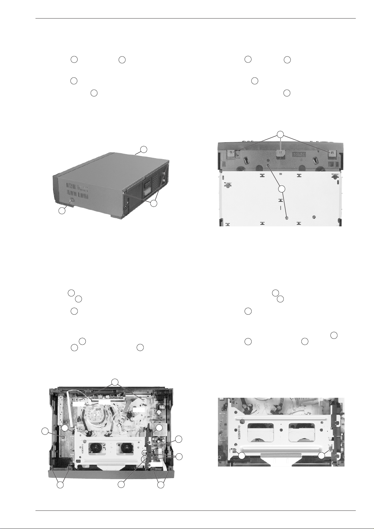
1. Entfernen der Gehäuseteile
1.1 Gehäuseoberteil
– 2 Schrauben A und 2 Schrauben B herausdrehen (Fig. 1).
– Gehäuseoberteil abnehmen.
1.2 Frontblende
– 3 Rasthaken C (Fig. 2) auf der Geräteunterseite lösen.
– Frontblende an der Unterseite nach vorne klappen und die Blende
an den oberen Haken D (Fig. 3) aushängen.
Montagehinweis:
– Beim Aufstecken der Frontblende auf den Geräterahmen ist die
Cassettenklappe zu öffnen. Der Cassettenklappenhebel (Pos. 0500,
siehe Seite 6-1) befindet sich dadurch vor der Cassettenklappe in
richtiger Position.
A
B
A
Service Instructions
1. Removing the Cabinet Parts
1.1 Cabinet Top
– Undo 2 screws A and 2 screws B (Fig. 1).
– Remove the cabinet top.
1.2 Front Panel
– Release 3 clamps C (Fig. 2) on the cabinet bottom.
– Turn the lower edge of the front panel towards the front and detach
the panel from the upper clamps D (Fig. 3).
Reassembly:
– When attaching the front panel to the cabinet frame, open the
cassette compartment door. In this way, the door opening lever
(Pos. 0500, see page 6-1) is positioned correctly in front of the
cassette compartment door.
C
I
Fig. 1 Fig. 2
2. Ausbauhinweise
2.1 Laufwerk
– Steckverbindungen (Fig. 3, CN181 / CN201 / CN351) zum Laufwerk
lösen.
– Arretierung E (Fig. 3) des Cassettenschachtes an den beiden
Aussparungen F nacheinander lösen und diesen dabei bis Anschlag nach innen schieben.
– 2 Schrauben G (Fig. 4) herausdrehen.
Hinweis: Der Schraubendreher sollte einen dünnen Schaft haben,
da die linke Schraube schwer zugänglich ist. Sollte kein geeigneter
Schraubendreher zur Verfügung stehen, ist der Cassettenschacht
auszubauen (siehe Kapitel "Laufwerk" Punkt 8.1) und anschließend
die 2 Schrauben G herauszudrehen.
– 2 Schrauben H (Fig. 3) und 2 Schrauben I (Fig. 2) herausdre-
2. Disassembly Instructions
2.1 Drive Mechanism
– Unplug the the plug-in connections (Fig. 3, CN181 / CN201 / CN351)
to the drive mechanism.
– Disengage the locking lever E (Fig. 3) of the cassette mechanism
successively at the two cutouts F and slide the mechanism inwards
to the stop.
– Undo 2 screws G (Fig. 4).
Note: The screwdriver should have a thin shank because access to
the left screw is difficult. If a suitable screwdriver is not available,
remove the cassette compartment mechanism (see "Drive Mecha-
nism", point 8.1) and subsequently undo the 2 screws G.
– Undo 2 screws H (Fig. 3) and 2 screws I (Fig. 2).
– To remove the Drive Mechanism, lift it in horizontal position.
hen.
– Laufwerk waagerecht nach oben herausnehmen.
H
CN181
CN351
CN201
K
O
D
E
O
CN701
K
F
D
G
G
Fig. 3 Fig. 4
GRUNDIG Service 1 - 17
Page 18
Allgemeiner Teil / General Section GV 29…, GV 9000…, GV 9300…
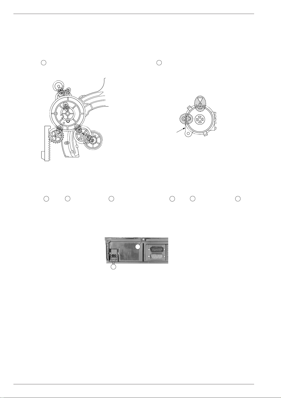
Montagehinweis:
– Der Einbau des Laufwerks muß in der Eject-Position erfolgen.
– Lademotormitnehmer/Schneckenrad in die am Lademotor ange-
gebene Pfeilrichtung so lange drehen, bis sich alle Zahnräder und
Hebel in der in Fig. 5 markierten Position befinden.
– Funktionswahlschalter S8001 durch Drehen des Zahnrades in
die Laufwerkposition Eject bringen (Fig. 5 / 6).
– Beim Aufsetzen des Laufwerks auf die Chassisplatte ist darauf zu
achten, daß die Sensoren für Bandanfang und Bandende in die
Abdeckungen O (Fig. 3) des Cassettenschachtes eintauchen. Das
Laufwerk muß leicht auf der Chassisplatte aufzusetzen sein, damit
die Steckverbindungen zur Chassisplatte richtig kontaktieren.
Reassembly:
– The drive mechanism is to be reassembled in Eject position.
– Turn the loading motor driver/worm gear in the direction of the
arrow on the loading motor until all gear wheels and levers are in
the position shorn in Fig. 5.
– Set the mode switch S8001 to Eject mode by turning the gear
wheel (Fig. 5/6).
– When putting the drive mechanism on to the chassis board take care
of the tape start and tape end sensors. They must plunge into the
covers O (Fig. 3) of the cassette mechanism. It must be possible
to put the drive mechanism easily on the chassis board to ensure
that the connectors to the chassis board are in good contact.
EJECT
S8001
Fig. 5 Fig. 6
2.2 Chassisplatte
– Laufwerk ausbauen (siehe Punkt 2.1).
– Gegebenenfalls Steckverbindung (Fig. 3, CN701) zur Bedieneinheit
lösen.
– je 2 Schrauben K (Fig. 3) / L (Fig. 7) und Schraube M (Fig. 7)
herausdrehen.
– Chassisplatte nach oben vorsichtig herausnehmen.
Sicherheitshinweis
– Nach dem Entfernen des Gehäuserahmens ist die Lötseite des
Netzteils frei zugänglich und damit auch alle lebensgefährlichen
Spannungen. Im Servicefall immer Trenntrafo benutzen.
L
Fig. 7
3. Wichtige Masseverbindungen!
Beim Zusammenbau des Gerätes ist darauf zu achten, daß die
Masseverbindungen zwischen Gehäuseboden und Chassisplatte,
Buchsenplatte und Gehäuseoberteil, Chassisplatte und Laufwerk
sowie Gehäuseboden und Gehäuseoberteil gewährleistet sind.
2.2 Chassis Board
– Remove the drive mechanism (see point 2.1).
– Disconnect the plug-in connections (Fig. 3, CN701) to the keyboard
control unit if necessary.
– Undo 2 screws K (Fig. 3) / L (Fig. 7) each and screw M (Fig. 7).
– Lift the chassis board carefully to remove it.
Safety Precaution:
– After having removed the cabinet frame the solder side of the power
supply board is freely accessible and so are all voltages dangerous
to life. Do not fail to use an isolating transformer during repairs!
M
3. WARNING: Chassis Connections!
When reassembling the machine make sure that the ground connections between the cabinet bottom and chassis board, socket board and
cabinet top, chassis board and drive mechanism, cabinet bottom and
cabinet top are in good order.
4. Durchführen von Messungen
Bei Messungen mit dem Oszilloskop an Halbleitern sollten Sie nur
Tastköpfe mit 10:1 - Teiler verwenden. Außerdem ist zu beachten, daß
nach vorheriger Messung mit AC-Kopplung der Koppelkondensator
des Oszilloskops aufgeladen sein kann. Durch die Entladung über das
Meßobjekt können Bauteile beschädigt werden.
5. Meßwerte und Oszillogramme
Bei den in den Schaltplänen und Oszillogrammen angegebenen
Meßwerten handelt es sich um Näherungswerte!
1 - 18 GRUNDIG Service
4. Carrying out Measurements
When making measurements on semi-conductors with an oscilloscope, ensure that the test probe is set to 10:1 dividing factor. If the
previous measurement was made on AC input, olease note that the
coupling capacitor in the oscilloscope will be charged. Discharge via
the item being checked can damage the components.
5. Measured Values and Oscillograms
The measured values given in the circuit diagrams and oscillograms
are approximates!
Page 19

GV 29…, GV 9000…, GV 9300… Fehlerdiagnoseprogramm
D
Fehlerdiagnoseprogramm
Die Geräte enthalten ein Fehlerdiagnoseprogramm, das sporadisch
auftretende Fehler erkennt und als Fehlercode speichert. Der Fehlercode und der Code für die Betriebsart, bei der der Fehler aufgetreten
ist, kann abgerufen werden.
Aufruf der Fehlerdiagnoseanzeige
– Im Standby-Betrieb die Taste ı so lange drücken (min. 10s) bis
die Displayanzeige wechselt:
Betriebsstundenzähler
Fehlercode
– Nach ca. 10s wechselt die Anzeige des Displays wieder in den
Standby-Betrieb.
Löschen des Fehlercodes und Betriebsartcodes
– Durch Drücken der Taste "0" während der Anzeige des Fehlercodes
und des Betriebsartcodes sind diese löschbar.
Betriebsartcode
Videokopfausgangssignal
Fehlercodes
"Fehler" gibt den aufgetretenen Fehler an.
"Status" nennt den Betriebszustand nach Auftreten des Fehlers.
"Ursache" gibt Bereiche an, in denen der Fehler zu suchen ist.
Code 00
Fehler: Kein erkennbarer Fehler aufgetreten.
Code 01
Fehler: Kopfscheibenmotor läuft nicht.
Status: Gerät schaltet in den Standby-Betrieb.
Ursache: Kopfscheibenmotor, Kopfscheibenmotor-Ansteue-
Code 02
Fehler: Wickelteller drehen sich nicht.
Status: Gerät schaltet in den Standby-Betrieb.
Ursache: Wickeltellerblockade, Riemen, Wickeltellerdreh-
Code 03
Fehler: Capstanmotor läuft nicht.
Status: Gerät schaltet in den Standby-Betrieb.
Ursache: Capstanmotor, Capstanmotor-Ansteuerung.
Code 04
Fehler: Band kann nicht eingefädelt werden, Ausfädeln funkStatus: Laufwerk fädelt aus, geht in Stellung INITIAL, Gerät
Ursache: Bandführungen der Fädelschlitten verhakt, Lademotor,
Code 05
Fehler: Ein- und Ausfädelfehler.
Status: Laufwerk steht an der Stelle an der der Fehler auftrat,
Ursache: Bandführungen der Fädelschlitten verhakt, Lademotor,
Code 06
Fehler: Cassette kann nicht ausgegeben werden.
Status: EJECT bei eingeschaltetem Gerät: Laufwerk geht in
Ursache: Laufwerk, Cassettenklappe.
Code 07
Fehler: Cassette kann nicht abgesenkt oder ausgegeben
Status: Laufwerk steht an der Stelle an der der Fehler auftrat,
Ursache: Cassette im Schacht verklemmt, Cassettenschacht-
rung, Cassettenband um die Kopfscheibe gewickelt.
moment zu gering.
tioniert.
schaltet in Standby-Betrieb.
Lademotoransteuerung.
Gerät schaltet in Standby-Betrieb.
Lademotoransteuerung.
Stellung STOP.
EJECT bei ausgeschaltetem Gerät (Standby): Laufwerk geht in Stellung INITIAL, Gerät geht in StandbyBetrieb.
werden.
Gerät schaltet in Standby-Betrieb.
mechanik, Cassettenschachtgetriebe.
Code 08/09
Fehler: Fehler beim Durchlauf der einzelnen Laufwerks-
positionen.
Status: Laufwerk steht an der Stelle an der der Fehler auftrat,
Gerät schaltet in Standby-Betrieb.
Ursache: Funktionswahlschalter.
Code 10
Fehler: Capstanmotor dreht sich nicht, Cassette wird nach
dem Einschieben wieder ausgegeben.
Status: Laufwerk geht in EJECT-Stellung.
Ursache: Capstanmotor, Capstanmotor-Ansteuerung.
Code 11
Fehler: Kopfscheibe dreht sich nicht, Cassette wird nach dem
Einschieben wieder ausgegeben.
Status: Laufwerk geht in EJECT-Stellung.
Ursache: Bandtrommeleinheit, Bandtrommel-Ansteuerung.
Code 12
Fehler: Riemenscheibe, Reibkupplung dreht sich nicht, Cas-
sette wird nach dem Einschieben wieder ausgege-
ben.
Status: Laufwerk geht in EJECT-Stellung.
Ursache: Riemenscheibe, Reibkupplung, Riemen, Drehmoment
der Reibkupplung.
Betriebsartcodes
Code Betriebsart
00 Cassette ausgegeben
01 Standby
02 Stop
03 Standbild
04 Aufnahme-Pause
05 Nachvertonung-Pause
06 Einzelbildfortschaltung
07 Zeitlupe
08 Wiedergabe
09 Aufnahme
10 Nachvertonung
11 Wiedergabe (2-fach)
12 Bildsuchlauf vorwärts
13 Bildsuchlauf rückwärts
14 Vorlauf
15 Rücklauf
16 Video-Insert
17 Video-Insert-Pause
18 Audio/Video-Insert
19 Wiedergabe rückwärts (2-fach)
99 sonstiges
Videokopfausgangssignal
Das Fehlerdiagnoseprogramm überwacht auch die Videokopfausgangssignale. Ist das Signal von einem Videokopf oder beiden Videoköpfen zu klein, wird in der Fehlerdiagnoseanzeige ein blinkendes "L"
angezeigt. Prüfen Sie dann die Trackingeinstellung, die eingelegte
Cassette, die Videoköpfe und die Signalwege. Das dabei ausgewertete Hüllkurvensignal der FM-Pakete (VD ENV-Signal) ist an IC301-(85)
meßbar.
4V
0,5V~ 0,95V
0V
Betriebsstundenzähler
In der Fehlerdiagnoseanzeige wird die Betriebsdauer der Kopfscheibe
zweistellig in 100-Stunden-Bereichen angezeigt.
Beispiel: Anzeige 10 = Betriebsstundenbereich 900 bis 999.
GRUNDIG Service 2 - 1
j
Page 20

Diagnostic Programme GV 29…, GV 9000…, GV 9300…
GB
Diagnostic Programme
These video recorders are provided with a Diagnostic Programme that
identifies occasionally occurring faults and stores the respective error
codes. The error code and the code of the operating mode in which the
error occurred can be called up.
Activating the diagnostic display
– Press and hold down the ı button (at least 10s) until the display
mode changes:
Operating hours meter
Error code
– After about 10s the display is reset to the Standby mode.
Clearing the error code and operating mode code
– These codes can be cleared by pressing the "0" button during the
display of the error code and the operating mode code.
Operating mode code
Video head output signal
Error codes
"Fault" specifies the fault occurred.
"Status" specifies the operating mode to which the VCR changes
"Cause" specifies locations to search for the fault.
Code 00
Fault: There is no abnormality in the mechanism.
Code 01
Fault: Headwheel motor does not rotate.
Status: The VCR switches to Standby mode.
Cause: Headwheel motor, drive to the headwheel motor,
Code 02
Fault: Reels do not rotate.
Status: VCR switches to Standby mode.
Cause: Blockage of reels, reel belt, reel torque is too low.
Code 03
Fault: Capstan motor does not rotate.
Status: VCR switches to Standby mode.
Cause: Capstan motor, drive to the capstan motor.
Code 04
Fault: Tape cannot be loaded. Unloading is ok.
Status: Mechanism unloads, changes to INITIAL position,
Cause: Jammed tape guides of the threading roller units,
Code 05
Fault: Loading and unloading the tape is not possible.
Status: Mechanism is in the position in which the fault oc-
Cause: Jammed tape guides of the threading roller units,
Code 06
Fault: Ejecting the cassette is not possible.
Status: EJECT with the VCR switched on: Mechanism changes
Cause: Mechanism, cassette front door.
Code 07
Fault: Lowering or ejecting the cassette is not possible.
Status: Mechanism is in the position in which the fault oc-
Cause: Cassette jammed within the cassette compartment,
when the fault occurs.
cassette tape wound around the headwheel.
VCR changes to Standby mode.
loading motor, drive to the loading motor.
curred, VCR switches to Standby mode.
loading motor, drive to the loading motor.
to STOP position.
EJECT with the VCR switched off (Standby): Mechanism changes to INITIAL position, VCR switches to
Standby mode.
curred, VCR switches to Standby mode.
cassette compartment mechanism, cassette com-
partment gears.
Code 08/09
Fault: Fault when sequentially switching through the indi-
vidual mechanism mode positions.
Status: Mechanism is in the position in which the fault oc-
curred, VCR switches to Standby mode.
Cause: Mode switch
Code 10
Fault: Capstan motor does not rotate, cassette is ejected
when having inserted it.
Status: Mechanism changes to the EJECT position.
Cause: Capstan motor, drive to the capstan motor.
Code 11
Fault: Headwheel does not rotate, cassette is ejected when
having inserted it.
Status: Mechanism changes to the EJECT position.
Cause: Tape drum assy, tape drum drive.
Code 12
Fault: Pulley, friction clutch does not rotate, cassette is
ejected when having inserted it.
Status: Mechanism changes to the EJECT position.
Cause: Pulley, friction clutch, belt, torque of friction clutch.
Operating mode codes
Code Operating mode
00 Cassette Out
01 Standby
02 Stop
03 Still
04 Record-Pause
05 Dubbing-Pause
06 Frame Advance
07 Slow
08 Play
09 Record
10 Dubbing
11 Play (2x speed)
12 Picture Search Forward
13 Picture Search Reverse
14 Fast Forward
15 Reverse
16 Video Insert
17 Video Insert-Pause
18 Audio/Video Insert
19 Reverse Play (2x speed)
99 others
Video head output signal
The Diagnostic Programme is also responsible for monitoring the
video head output signals. If the signal of one or of the two video heads
is too low, the letter "L" will flash in the diagnostic display. In this case,
check the tracking position, the inserted cassette, the video heads and
the signal paths. The evaluated envelope signal of the FM packages
(VD ENV-Signal) can be measured at IC301-(85).
4V
0.5V~ 0.95V
0V
Operating hours meter
The operating hours of the headwheel are indicated in the diagnostic
display as two-digit numbers by hundreds.
Example: Indication 10 = operating hours ranging from 900 to 999.
2 - 2 GRUNDIG Service
k
Page 21
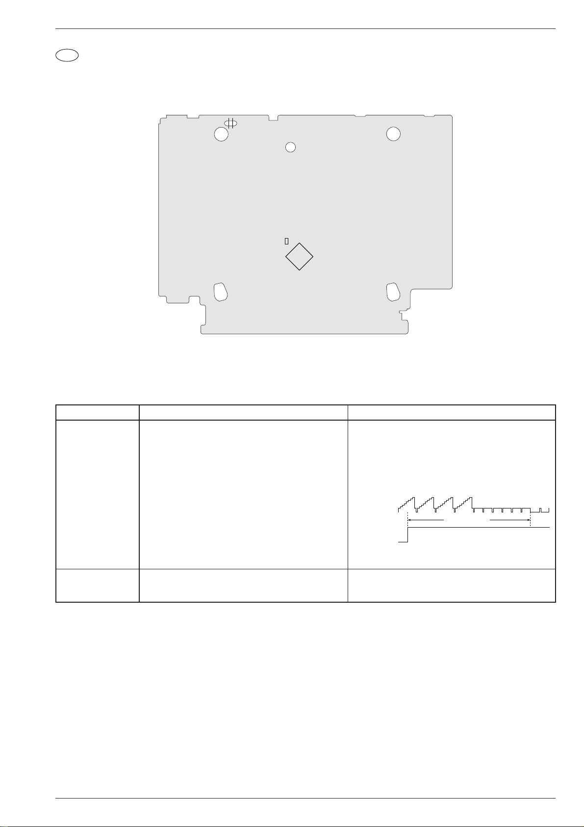
GV 29…, GV 9000…, GV 9300… Abgleichvorschriften
D
Abgleichvorschriften
1. Chassisplatte
Ansicht von der Lötseite
TP182
TP183
C3016
IC301
Meßgeräte / Meßmittel: Zweikanal-Oszilloskop mit Tastköpfe 10:1, Farbgenerator, Testcassette, Videocassette von Markenhersteller
Servicearbeiten nach Austausch …
… der Bandtrommel: Abgleich Nr. 1, 2
… des IC304: Abgleich Nr. 1, 2
Abgleich Vorbereitung Abgleichvorgang
1. KopfradLagengeber
Oszilloskop; Kanal 1 (Triggerung):......................... TP183
Kanal 2: ................................... Buchse Euro-AV1-(19)
Testcassette wiedergeben.
Taste K sofort nach Erscheinen des Wiedergabe-Bildes
3 Mal kurzzeitig antippen. Anschließend erfolgt der automatische Abgleich.
•Automatischer Abgleich: Der Abgleichvorgang wird im
Display angezeigt. Dabei läuft der Zähler von "P: 0:01" bis
maximal "P: 2:55". Beim eingestellten Wert bleibt der
Zähler stehen und ist manuell abgleichbar.
•Manueller Abgleich: Mit den Tasten Ü oder * ist der
Kopfumschaltimpuls auf 6,5 ±0,5 Zeilen vor den VertikalSynchronimpulsen einzustellen.
Kanal 2:
1V/div 50µs/div
Video-Ausgang
Kanal 1:
2V/div 50µs/div
Kopfumschaltimpuls
Testbetrieb verlassen durch Drücken der Taste u. Im Display erscheint kurzzeitig "P:– : –".
2. Standbild optimieren
FBAS-Signal an der EURO-AV1-Buchse einspeisen und
im Standardplay-Betrieb aufzeichnen.
Mit den Tasten C / D das Standbild nach subjektiv
bestem Eindruck einstellen.
Eigenaufnahme wiedergeben und Taste Ó drücken.
6.5 ±0.5H (Zeilen)
V-Sync.
GRUNDIG Service 3 - 1
j
Page 22
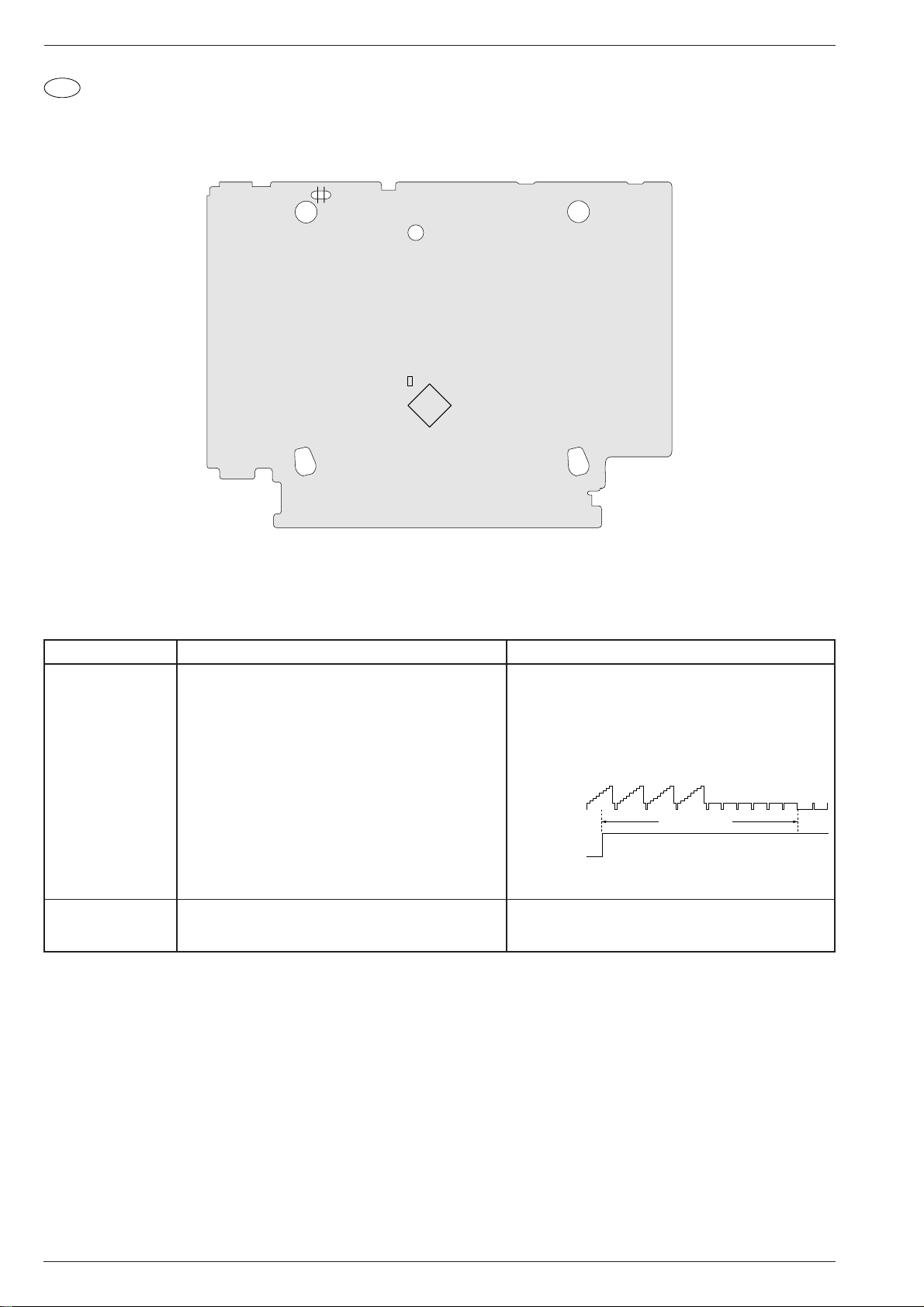
Adjustment Procedures GV 29…, GV 9000…, GV 9300…
GB
Adjustment Procedures
1. Chassis Board
View of Solder Side
TP182
TP183
C3016
IC301
Test equipment / aids: Two-channel oscilloscope with 10:1 probes, voltmeter, colour generator, test cassette, branded video cassette
Service works on replacement of …
… the tape drum: Adjustment No. 1, 2
… IC304: Adjustment No. 1, 2
Adjustment Preparation Adjustment Procedure
1. Headwheel
Position Indicator
Oscilloscope: Channel 1 (trigger):.......................... TP183
Channel 2: ................................. Euro-AV1-(19) socket
Play test cassette.
When the playback picture appears touch the K button
three times immediately. The automatic adjustment mode
will start.
•Automatic adjustment: The adjustment process is
indicated on the display. The meter counts from "P: 0:01"
to maximum "P: 2:55". The meter will stop at the set value.
The value can then be adjusted manually.
•Manual adjustment: Use the buttons Ü or * to set the
head switching pulse to 6.5 ±0.5 lines before the vertical
sync pulses.
Channel 2:
1V/div 50µs/div
Video output
Channel 1:
2V/div 50µs/div
Head switching pulse
6.5 ±0.5H (lines)
Press button u to leave the test mode. The indication
"P:– : –" appears for a short time on the display.
2. Still Picture
Optimisation
Feed a CCVS signal into the EURO-AV1 socket and
record it in Standardplay mode.
With buttons C / D set the still picture according to your
best personal impression.
Play back this recording and press button Ó .
V-sync
3 - 2 GRUNDIG Service
k
Page 23

GV 29…, GV 9000…, GV 9300… Platinenabbildungen und Schaltpläne / Layout of PCBs and Circuit Diagrams
Reference
Oscillograms....4-14
AD-A................4-29
CP-1 ................4-11
MC-A ...............4-19
PW-A...............4-17
SY-A................4-18
TB-1.................4-31
TC-A................4-29
TM-1................4-22
TM-A................4-23
VA-A................4-25
Platinenabbildungen und Schaltpläne
Layout of PCBs and Circuit Diagrams
Verdrahtungsplan
Wiring Diagram
GV 29…, GV 9000…, GV 9300… Platinenabbildungen und Schaltpläne / Layout of PCBs and Circuit Diagrams
(GV29)
(GV9000/9300)
GV29
GV9000/9300
GV29
GV9000/9300
ONLY FOR
4 HEAD
ONLY FOR
2 HEAD
GRUNDIG Service 4 - 1 GRUNDIG Service 4 - 2
Page 24
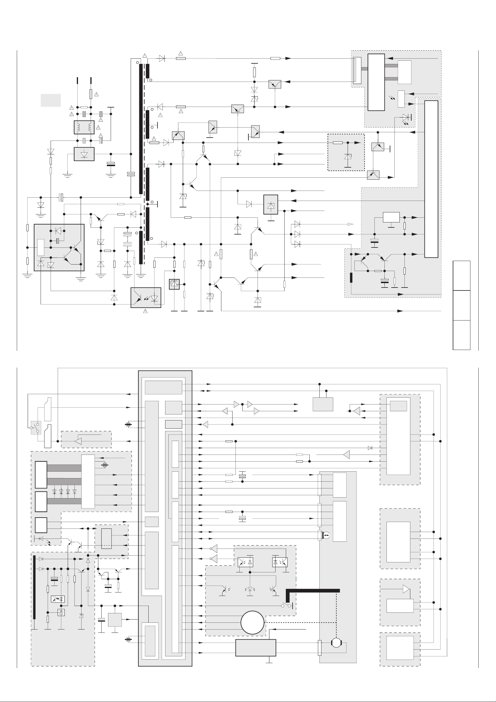
4 - 3 GRUNDIG Service 4 - 4 GRUNDIG Service
Start
SWD (PS) 37V
POWER CTL
SWD 5V(AD)
SWD 5V
SWD (PS) -23V
Life
Ground
HEATER +
HEATER -
CHASSIS
C5010
D5001
F5001
DELAY
CONTROL
OVERLOAD
ALWAYS 5.8V (LED)
SWD (PS) 12V
SWD 9V
SWD (PS) 13V (MC)
(POWER SAVE) PS CTL
Overvoltage
Protection
SAVE MODE
Feed Back
CONTROL
IC501
IC511
D5013
D5019
D5012
D5016D5015
Q5002
523
1
467
D5002
D5014
D5101
D5106
D5102
D5110
Q5103
Q5114
PR512
SWD (PS) 5V
Q5102
(PS) = Power Save
D5108
D5111
D5107
Q5101
Q5104
Q5120
Q5116
D5112
Q5115
Q5112
Q5111
D5103
R5110
D5104
R5120
Q5113
Q5110
D5115
D5109
D5116
D5105 PR511
SWD (PS) 13V
C5012
C5014/16
C5013
D5011
6,8V
R5121
-23V
+13V
+5,8V
97
Low Power = H
Stand By; On = L
(Low Power) Stand By = L
On = H
POWER SAVE
LED
C3017
25
IR
RR701
Clock
Keyboard
DISPLAY
5
R5015
R5014
IC512
PR513
Q5117
ALWAYS 5V(2)
D5120
D5119
FLD DRIVE
KEY SCAN
ALWAYS 5V (FL)
POWER DOWN
BACK UP 5V
RESET
ALWAYS 5V (IR)
ALWAYS
5V (IR)
ALWAYS 5V(FL)
IC 301
IC305
10
80
36; 42
System Controller
D5118
ALWAYS 5V(1)
6,2V
5,6V
ca.5.6V
5,6V
Q3010 Q3009
C3526
L3065
IC701
TM-A
SY-A
PW-A
33V
D3401
R3309
SY-A
D5101
D5013
IC511
RESET
REMOCON
POWER
SAVE
Display
Keyboard
Remote
Control
RC
Power-Supply
Control
POWER DOWN
POWER
CTL
Clock / Date
Timer
Tuning- & System Control
Key 0…3
IC301
5
97
36; 42
80
25
10
+13V
40
41
37
38
RR701
96AV CTL
8
SWD (PS)12V
Q1008/1009
SEGt a…l (Anoden)
GRID 1…9 G
DIODE OPTION
D5102
PW-A
Back
Up
FLD DRIVE (IC701)
& KEY SCAN
Euro-AV 1
ALWAYS 5V (FL)
FLD DATA IN
FLD DATA OUT
FLD CLK
25
18
24
23
TM-A
15
16
14
27
22
FLD CS
ALWAYS 5V (IR)
ca. 6V Q5120
Q5117
Q5116
9
M
MECHANISM
MODE
SWITCH
11
12
8
Lift
SAFETY/FL SW
D8001D8002 D8003
89
88
3
4 Q3007
Q3008
PC802
PC801
TAPE END
TAPE START
SUPPLY TAKE OFF
75
74
C-FG
C-VS33
67
68 FG OUT
D-FG
D-PG
Drum Frequency Generator
Drum Phase Generator
Capstan Frequency Generator
Capstan Velocity Speed
65
66
CTL+
CTL-
20 MC-FR
Motor Control - Foreward / Reverse
34 D-VS Drum Velocity SpeedD-VS
VLOCK / QVD
RF SWP
ENV DET (Autotrack)
YC AD MUTE
73
ALWAYS 5V (IR)
ALWAYS 5V (2)
OSD
SYNC
SEP
Seriell Interface
& I
2
C-Bus
VA-A
TC-A
IC141
VPS / PDC
Tuner
Modulator
IF-Amplifier
PLL-Demod.
SIF-Amplifier
FM-Demod.
SY-A
IC861
Video & Audio
I / O-Selector
(2 Euro-AV with
decoder only
MECHANISM
17
50
49
47
D1001
C SYNC
VA-A
EEPROM
IC304
18
25
26
8
Euro-AV 2
FSS IN
LO-MOTOR -
8
6
(ML-S)
LO-MOTOR +
8/9
CTL HEAD
(ML-D)
Y / C & audio processor
with CCD, with input- output
selector and headamplifier
IC101
MC-A
S8001S8002
85
99
60
23
24
Drum Control Head Control
Capstan Motor Driver
Drum
Motor
Driver
Deck Control
DATA
CLK
SWD (PS)13V; SWD 5V
SWD (PS)13V
SWD (PS)13V
Loading Motor Drive
IC302
CN352
CN201
CN801
CN351
IC5106
IC5120 IC5118
SY-A
93
10
11
Q1007
FSC
66
Q1006
CCD
49
24
23
26
28
29
PB ENV (PB FM)
TP182
Q1010
VD (TO MCOM)
VD (from MC)
95
Q3062/3065
Q3061
REC H 30
28
(COIN)
62
74
SWD 5V
Capstan Control
2
10
3
4
1
H AMP SW
PB L
Q8604
Q8605
44
16
16
VD OUT (AV)
Q1012
Q1001
VD OUT (CV)
98
ROTARY
(NP/LP)
(Head Switch Pulse)
VD
(FROM MCOM)
Q1401
4
Platinenabbildungen und Schaltpläne / Layout of PCBs and Circuit Diagrams GV 29…, GV 9000…, GV 9300… Platinenabbildungen und Schaltpläne / Layout of PCBs and Circuit Diagrams GV 29…, GV 9000…, GV 9300…
Blockschaltplan – Netzteil
Block Circuit Diagram – Power Supply
Reference
Oscillograms....4-14
AD-A................4-29
CP-1 ................4-11
MC-A ...............4-19
PW-A...............4-17
SY-A................4-18
TB-1.................4-31
TC-A................4-29
TM-1................4-22
TM-A................4-23
VA-A................4-25
Blockschaltplan / Block Circuit Diagram – Digital
Page 25

GV 29…, GV 9000…, GV 9300… Platinenabbildungen und Schaltpläne / Layout of PCBs and Circuit Diagrams
Reference
Oscillograms....4-14
AD-A................4-29
CP-1 ................4-11
MC-A ...............4-19
PW-A...............4-17
SY-A................4-18
TB-1.................4-31
TC-A................4-29
TM-1................4-22
TM-A................4-23
VA-A................4-25
Blockschaltplan / Block Circuit Diagram – Digital
GV 29…, GV 9000…, GV 9300… Platinenabbildungen und Schaltpläne / Layout of PCBs and Circuit Diagrams
LOADING MOTOR
MECHANISM
MODE SWITCH
TAKE-UP
REEL
SENSOR
SUPPLY
REEL
SENSOR
RR701
IR REMOTE CONTROL
RECEIVER
OPERATION
KEY-MATRIX
(TM-1 BOARD)
DISPLAY
(FLD)
HEATER+
ML
ROTARY
SW
+
-
KEY IN 0 ~ KEY IN 3
B ~ K (KEY SCAN)
SEG A
~
SEG L
SEGMENT
G1 ~G9
GRID
ALWAYS 5V
(TO PW-A)
POWER CTL
(TO PW-A)
IC302
10
+
2
-
TAPE END LED
FL START SW/
ERASE PREVENTION
SWITCH
FLD DRIVE
AND KEY SCAN
PS CTL
IC305
LOADING
MOTOR DRIVER
WAFEFORM SHAPE
WAFEFORM SHAPE
TAPE TOP SENSOR
TAPE END SENSOR
KEY IN 0
26
~
~
KEY IN 3
29
IC701
SEG A
31
~
~ ~
42
SEG L
6
G1
~
15
G9
Q3009,Q3010
POWER DOWN DET
INITIALIZE
RESET
Q3008
Q3007
NCS
SCK
SDI
SDO
4
3
5 (GV29)
22 (GV9…)
23
24
25
80
POWER DOWN
97
POWER SAVE CONTROL
10
POWER CTL
25
RESET
6
ML-D
7
ML-S
9
SW DATA 0
11
SW DATA 1
12
SW DATA 2
3
T REEL P.
4
S REEL P.
88
T.TOP.S
89
T.END.S
8
FL START
5
+SAFETY SW
REMOCON
IC301
(GV9000/9300) FSS IN
(1/2)
SYSTEM CONTROL, OSD
TIMER, TUNING CONTROL
27
FLD CS
14
FLD CLK
16
FLD DATA OUT
15
FLD DATA IN
37
OSCO
38
OSCI
40
XI
41
XO
54
FSC FSC
ALTOFF H ALTOFF H
NORM A CTL NORM A CTL
YCA MUTE
A MUTE
VD IN FIL
VD OUT
(GV29) AV CTL
I2C CLK
I2C DATA
63
60
REC H REC H
44
PB L
91
62
78
49
VD IN
50
47
96 (GV29)
95 (GV9000/9300)
18
17
X3002
14.32MHz
X3001
32KHZ
PB L
YCA MUTE
A MUTE
Q3061
Q3062
BUF OSD SIG IN
Q3065
OSD SIG OUT
AV CTL (GV29)
FSS IN (GV9000/9300)
YCA CLK (GV29)
I2C CLK (GV9000/9300)
YCA DATA (GV29)
I2C DATA (GV9000/9300)
MPU
IC304
I2C ROM
PLL CLK,S CLK
PLL DATA,S DATA
CH+ CLK
CH+ DATA
ONLY GV9000/9300
TO TB-1
TO VA-A
AD-A
TO TB-1
TO VA-A
CFG
DPG IN
DFG IN
CTL+
CTL-
VD(TO MCOM)
ENV DET
QVD
RF SWP
ENV SW
H AMP SW
ROTARY
ONLY GV900/9300
TRACKING
CTL
(1/2)
(MN101D01)
TAPE SPEED
PLAY
REC
F-DIVIDER
DRUM
SPEED CTL
WAVEFORM
SHAPER
DET
RF SW
CAP
PHASE CTL
CAP
SPEED CTL
100
H.A.SW
ROTARY
DRUM
PHASE CTL
+
AF SW
DUMMY
V
CTL HEAD
24
V LOCK P
99
H AMP SW
98
ROTARY
20
MC FR
23
RF SWP
30
AF SWP
33
+
34
L.P.F
D/A CONVERTER
L.P.F
D/A CONVERTER
CTL-
CTL+
-
MC-FR
C-FG
MECHANISM
D-PG
+
CAPSTAN
MOTOR
DRUM
MOTOR
HEAD
IC301
REC CTL
DRIVER
Vref
WAVEFORM
SHAPER
SERVO
84
85
74
75
70
68
67
66
65
D-FG
TO
VA-A
3 IN 1 TUNER
ANT
IN
5
S CLK
3
S DATA
(GV29) 10
11
S CLK
S DATA
(GV29) 11
12
GRUNDIG Service 4 - 5 GRUNDIG Service 4 - 6
(TU/IF BLOCK)
AIN
VIN
SW1
SW2
AFT
A.OUT
V.OUT
2
A OUT CV
6
V OUT CV
19
20
23
21
24
TU AUDIO NORM (TO AD-A)
VIDEO OUT(TO VA-A)
87
TU SW1
86
TU SW2
83
AFT C
C SYNC
50
SYNC SEP
Page 26

Platinenabbildungen und Schaltpläne / Layout of PCBs and Circuit Diagrams GV 29…, GV 9000…, GV 9300… Platinenabbildungen und Schaltpläne / Layout of PCBs and Circuit Diagrams GV 29…, GV 9000…, GV 9300…
Reference
Oscillograms....4-14
AD-A................4-29
CP-1 ................4-11
MC-A ...............4-19
PW-A...............4-17
SY-A................4-18
TB-1.................4-31
TC-A................4-29
TM-1................4-22
TM-A................4-23
VA-A................4-25
Blockschaltplan / Block Circuit Diagram – Video/Chroma
ONLY LP
HEAD DRUM
CH2
LP HEAD
CH1
CH2
SP HEAD
CH1
TO SY-A
ENV DET
ENV SW
TP182
PB ENV
BUF
Q1001
IC101
82
83
84
85
88
89
90
91
93
94
74
ONLY GV29/9000
ONLY GV9300
REC
FM AGC
DET
ENV
DET
(LA71590M)
HEAD AMP
RF PROCESSING
RF SWP
ROTARY
TP183
COMP
OUT
REC
FM AGC
1110
73 72 71 70 69
SECAM DET
PAL M DET
KIL
DET
P
R
KIL
BPF
NAP
KIL
BD
+
PB_FM
AGC
PB_PM
EQ.
REC
FM AGC
FM
MOD
W/D
CLIP
4.43MHz
X1002
67 66
VXO2
P
R
R
CONV
P
BPF2
Q1002
Q1013
SUB
LPF
FM
DEM
DOUBLE
LIM
EQ AMP
REC
APC
DET
C-LPF
B-UP
AMP
REC H
Q1006
BUF
6364
VXO1
ACC
DET
ACC
DETAIL
EMPHA
1817
61 59 57
COMB
AMP
CCD
LPF
P
P
R
P
R
P
R
CLAMP
2120
BUF
Q1003
BPF1
R
Y.N.R
Y-LPF
R
1/2
R
P
SERIAL
DECODER
22 23 24
54 52 51
C COMB
NL
DE_EMP
PB_C
P
FBC
P
SYNC
SEP
R
Chara
IMS
26
CCD
DELAY PROCESSING
PIC-CTL
ANR
PB_Y
Y/C
MIX
P
R
Q1005
BUF
II PLL
CLAMP
28
SYNC
DET
Y_DELAY
6DB
AMP
29 30
PB_EQ
CTL
FILTER
Q3061
Q3062
Q3065
DELAYED
SIGNAL
CLK
AGC
TC2
49,50
49
46
45
43
41
38
36
34
32
31
VIN
Q1004
BUF
ON SCREEN
DISPLAY
IC301
FSC
VD IN(AV1)
TO CN871 (EURO AV1)
VD IN(TU)
TO TUNER
(GV29)
REC H
47
VOUT
Q1012
BUF.
ONLY GV29
Q1010
BUF.
Q1001
BUF.
V OUT
TO CN871 (GV29)
(EURO AV1)
V OUT
TO 3IN1_TUNER
(GV9000/9300)
V OUT
TO TUNER (GV29)
TO TB-1 IC861
(GV9000/9300)
4 - 7 GRUNDIG Service 4 - 8 GRUNDIG Service
C SYNC
V LOCK P
TO SY-A
I2C DATA
I2C CLK
Page 27

GV 29…, GV 9000…, GV 9300… Platinenabbildungen und Schaltpläne / Layout of PCBs and Circuit Diagrams
Reference
Oscillograms....4-14
AD-A................4-29
CP-1 ................4-11
MC-A ...............4-19
PW-A...............4-17
SY-A................4-18
TB-1.................4-31
TC-A................4-29
TM-1................4-22
TM-A................4-23
VA-A................4-25
GV 29…, GV 9000…, GV 9300… Platinenabbildungen und Schaltpläne / Layout of PCBs and Circuit Diagrams
Blockschaltplan / Block Circuit Diagram – Audio
MECHANISM BLOCK
AUDIO
R/P HEAD
AUDIO
E HEAD
FULL
E HEAD
AV1
TO CN871 (GV29)
TO TB-1 IC861 (GV9000/9300)
TUNER
AUDIO
ONLY GV29
REC/PB
T2001
Q2002 Q2005
70KHz
OSC
BIAS
BIAS
LEVEL
CONTROL
&
TO TUNER
REC H
Q2029
76
78
80
100
IC101
LA71590M
1
(1/2)
EQ
AMP
LINER AUDIO
EE
REC
ALC
LINE
PB
AMP
MUTE
ALC
DET
LP
AUTO
BIAS
4
5
99
6
REC
AMP
10
96
77
DRIVE
MUTE
Q2371
Q2372
98
7
YCA AD MUTE
TO SY-A
AUDIO OUT (GV29)
TO TB-1 IC861
(GV900/9300)
AD OUT(CV) TO SY-A
AD MUTE
TO SY-A
BIAS
CONT
Q2001
GV 9000… / GV 9300…:
Blockschaltplan / Block Circuit Diagram – IN/OUT
VD IN TU
36
6dB
BUF
BUF
6dB
35
31
29
26
25
23
22
21
20
19
CONTROL
CH+ AUDIO IN
101214161820
111315171921
2468
13579
CH+, AUDIO OUT
1
5
9
4
6
12
14
16
18
IC861
INTERFACE
2468
1357911
FSS OUT
CONTROL
CONTROL
CLAMP
CLAMP
CLAMP
RGB(BLUE)
RGB(GREEN)
RGB(RED)
CN872
SERIAL
CONTROL
CLAMP
CONTROL
Q8604
PB L
EURO AV
VIDEO IN
CN871
GRUNDIG Service 4 - 9 GRUNDIG Service 4 - 10
Q8605
EURO AV DECODER
1315171921
BLANKING
EURO AV, VIDEO OUT
CH+, VIDEO IN
AUDIO IN
101214161820
AUDIO OUT
AD IN TU
AD OUT
AD IN
CH+ CLK
CH+ DATA
VD IN
VD OUT
FSS IN
(SYSCON IC301)
IC301
17 18
23
24
processing
Videosignal-
IC101
processing
Videosignal-
System Controller
7
IC141
6
VPS / PDC
VD (TO MCOM)29 VD OUT (AV)
38
36
34 VD IN (TU)
80
76
78
96
TC-A
16
Q1401
DATA
CLK
Q3062/3065
VD IN (AV1)
VD IN (AV2)
AD IN ( TU )
AD IN (AV1)
AD IN (AV2)
AD OUT
Q1012
OSD
49 47
Q1010 (delete by IC861)
Q1001
Modu-
lator
96
AV CTL
78
AD MUTE
VD (FR MCOM)
VD (CV)
TU / IF / DEMOD
(Audio & Video)
AD OUT (CV)
Q1008 / Q1009 (VA-A)
Mute (AD-A)
Q2371/2372
all models without IC861
25
26
19
21
16
only for 2 Euro-AV with decoder
9
31
36
2-Euro-AV without decoder
IC861
20
14 20
35
1
1; 3
2; 6
4
23
18
29
5
1; 3
2; 6
IC301/95
8
19
19
20
8FSS IN
AV1 (TV)
A V2 (DECODER)
Page 28

Platinenabbildungen und Schaltpläne / Layout of PCBs and Circuit Diagrams GV 29…, GV 9000…, GV 9300… Platinenabbildungen und Schaltpläne / Layout of PCBs and Circuit Diagrams GV 29…, GV 9000…, GV 9300…
ABCDEFGHI JKLMNOPQ
ABCDEFGHI JKLMNOPQ
1
2
3
4
5
6
7
8
9
10
11
12
1
2
3
4
5
6
7
8
9
10
11
12
CP-1: Chassisplatte / Chassis Board
Ansicht von der Lötseite (konventionelle Bestückung) / View of Solder Side (Conventional Assembly)
4 - 11 GRUNDIG Service 4 - 12 GRUNDIG Service
Page 29

GV 29…, GV 9000…, GV 9300… Platinenabbildungen und Schaltpläne / Layout of PCBs and Circuit Diagrams
Koordinaten für die Bauteile der Bestückungs- und Lötseite
Coordinates of the components on the Component and Solder Side
A7001 I 1
C1001 H 10
C1002 H 10
C1003 H 10
C1004 I 10
C1005 H 10
C1006 H 10
C1007 H 10
C1008 H 9
C1009 H 9
C1010 H 9
C1011 H 9
C1012 G 9
C1013 I 9
C1014 H 9
C1015 H 9
C1016 I 9
C1017 I 9
C1018 F 8
C1019 I 9
C1020 G 9
C1021 I 9
C1022 I 8
C1023 I 8
C1024 I 8
C1025 I 9
C1026 I 9
C1027 I 8
C1028 J 9
C1029 J 9
C1030 I 8
C1031 J 9
C1032 J 8
C1033 J 8
C1034 J 8
C1035 J 8
C1036 K 8
C1037 J 9
C1038 K 8
C1039 J 8
C1040 J 9
C1041 J 9
C1042 J 9
C1043 H 9
C1045 H 9
C1046 G 9
C1047 H 9
C1048 G 8
C1049 I 8
C1050 H 8
C1051 H 8
C1052 I 9
C1053 E 11
C1054 E 10
C1055 H 9
C1056 H 8
C1059 J 8
C1060 G 9
C1061 H 12
C1062 I 8
C1063 G 8
C1064 H 10
C1066 F 10
C1067 G 10
C1401 E 10
C1402 E 10
C1403 E 9
C1404 E 9
C1405 E 8
C1410 D 9
C1412 E 9
C1414 E 10
C1415 D 8
C1416 D 10
C1419 E 9
C1801 J 11
C1802 K 11
C1803 J 10
C1804 K 11
C1805 J 11
C1806 K 11
C1807 K 10
C1808 K 10
C1809 K 10
C1810 J 11
C1811 J 10
C2001 K 9
C2002 K 8
C2003 K 9
C2004 K 9
C2005 K 10
C2006 K 9
C2007 K 10
C2008 I 11
C2009 I 11
C2010 J 11
C2011 H 12
C2012 F 11
C2013 G 11
C2014 G 11
C2015 H 10
C2016 H 11
C2017 H 11
C2018 H 10
C2019 I 11
C2020 I 11
C2021 I 11
C2022 G 11
C2023 I 11
C2024 K 7
C2301 N 10
C2302 N 10
C2303 M 10
C2304 M 11
C2305 N 10
C2306 L 10
C2307 M 10
C2308 L 9
C2309 K 9
C2310 K 8
C2311 O 10
C2312 L 8
C2313 O 10
C2314 L 9
C2315 O 11
C2316 M 8
C2317 O 12
C2318 M 9
C2320 M 9
C2322 N 10
C2323 M 10
C2324 L 10
C2327 L 9
C2328 Q 12
C2351 L 9
C2352 N 8
C2353 L 8
C2354 N 8
C2355 M 9
C2356 N 8
C2357 M 9
C2358 N 8
C2361 P 12
C2362 O 11
C2363 M 12
C2372 K 12
C2373 N 10
C2901 K 10
C2921 L 10
C2922 L 10
C2923 L 10
C2924 L 10
C2925 K 10
C2926 L 10
C2929 L 10
C2930 L 10
C3001 I 4
C3002 I 4
C3003 J 4
C3004 J 4
C3005 D 7
C3006 N 6
C3008 K 2
C3010 K 3
C3011 D 5
C3012 K 3
C3013 D 5
C3014 E 5
C3015 E 3
C3016 H 5
C3017 L 2
C3018 K 2
C3019 G 5
C3021 J 3
C3024 H 6
C3025 F 3
C3026 F 3
C3027 F 3
C3035 L 5
C3036 L 5
C3037 F 6
C3040 L 2
C3041 L 2
C3042 K 3
C3043 K 3
C3044 G 6
C3045 F 4
C3051 F 4
C3052 F 4
C3059 M 3
C3061 I 4
C3064 K 5
C3065 L 5
C3066 M 4
C3067 M 4
C3068 L 4
C3080 O 6
C3081 O 7
C3082 P 7
C3083 P 7
C3084 P 6
C3085 F 4
C3087 O 7
C3301 P 9
C3302 P 9
C3304 Q 10
C3305 Q 9
C3309 Q 10
C3310 Q 10
C3312 Q 10
C3313 P 4
C3314 O 4
C3316 O 4
C3317 Q 12
C3318 P 11
C3319 Q 12
C3320 P 11
C3321 Q 11
C3324 P 5
C3325 P 5
C3326 P 4
C3327 P 4
C3328 P 5
C3329 P 5
C3330 P 5
C3331 P 4
C3333 Q 12
C3334 Q 11
C3335 Q 12
C3404 O 7
C3405 Q 11
C3502 K 6
C3503 I 5
C3504 F 6
C3505 G 6
C3506 I 5
C3507 K 5
C3508 J 6
C3510 J 5
C3511 O 7
C3512 O 7
C3513 H 5
C3514 H 5
C3516 E 3
C3517 E 3
C3519 D 11
C3520 L 4
C3521 L 4
C3522 G 3
C3523 F 3
C3524 J 5
C3525 J 5
C3526 J 5
C3527 J 5
C3528 E 4
C3530 J 4
C3531 I 4
C5001 B 12
C5002 B 11
C5005 B 11
C5007 C 10
C5010 B 9
C5012 A 8
C5013 A 9
C5014 C 8
C5015 A 9
C5016 C 8
C5017 B 9
C5101 B 6
C5102 A 5
C5103 B 7
C5104 A 6
C5105 C 7
C5106 A 6
C5107 A 6
C5111 B 4
C5112 C 4
C5113 A 4
C5114 B 4
C5115 B 5
C5116 A 4
C5117 C 4
C5118 C 4
C5119 B 4
C5122 C 6
C5125 C 4
C5127 C 5
C5128 C 5
C5129 C 3
C5134 A 7
C5135 C 6
C7001 H 1
C7002 H 1
C7003 H 1
C7004 H 1
C7005 L 1
C7006 H 3
C7007 E 2
C8001 K 3
CN181 L 11
CN201 F 12
CN233 N 9
CN234 O 3
CN261 P 10
CN263 P 5
CN351 O 8
CN352 D 11
CN501 A 12
CN701 A 3
CN702 O 3
CN801 K 3
CN851 J 12
CN861 H 12
D1001 H 8
D1005 G 9
D1006 G 9
D1007 F 9
D1008 G 8
D1009 E 11
D1010 E 12
D1011 E 13
D2301 P 12
D3001 K 3
D3002 F 5
D3401 O 5
D3501 I 5
D3502 I 5
D5001 A 10
D5002 B 10
D5011 A 9
D5012 B 8
D5013 C 8
D5014 B 8
D5015 A 9
D5016 B 9
D5017 B 9
D5018 B 9
D5019 C 9
D5101 B 7
D5102 B 7
D5103 C 7
D5104 A 7
D5105 A 7
D5107 B 4
D5108 A 4
D5109 A 6
D5110 B 5
D5111 B 6
D5112 C 5
D5113 B 5
D5115 A 6
D5116 A 6
D5118 C 3
D5119 C 3
D5120 C 3
D5125 C 4
D7001 D 1
D7002 D 1
D7003 E 1
D7004 D 1
D7005 D 1
D7006 D 1
D7007 D 1
D7008 D 1
D7009 E 2
D7010 E 2
D7011 E 2
D7012 E 2
D7013 E 2
D7014 E 2
D7015 F 2
D7016 E 2
D7017 K 2
D7018 K 2
D7019 J 2
D7021 E 1
D7022 E 1
D7023 F 1
D7024 E 1
D7025 E 1
D7026 E 1
D7027 F 1
D7028 E 1
D7029 K 1
D8001 D 7
D8002 N 7
D8003 I 6
F5001 C 11
IC101 J 10
IC141 E 9
IC141 E 9
IC141 E 9
IC231 M 10
IC301 H 4
IC302 L 2
IC303 K 2
IC304 F 3
IC305 K 2
IC306 P 7
IC341 O 6
IC501 B 9
IC511 C 6
IC512 B 5
IC701 I 2
JK231 O 11
JW101 I 10
JW101 I 10
JW101 K 12
JW181 M 12
JW231 M 11
JW261 B 4
JW261 P 3
JW263 P 6
JW511 A 4
JW512 C 6
JW513 C 4
L1001 G 9
L1002 G 9
L1003 G 9
L1004 I 8
L1005 K 9
L1006 I 7
L1007 H 10
L1801 K 11
L2004 G 12
L2351 F 11
L2352 M 7
L2373 L 9
L2901 K 10
L3010 J 4
L3061 M 5
L3063 F 3
L3064 K 5
L3065 G 5
L3066 G 4
L3080 O 6
L3301 O 11
L3302 O 5
L3304 P 11
L3305 P 9
L3306 P 8
L3307 P 5
L5001 A 10
L5101 C 6
L5102 B 6
PC801 G 5
PC802 K 5
PR511 A 7
PR512 B 4
PR513 A 4
Q1001 E 11
Q1002 G 10
Q1003 G 9
Q1004 I 8
Q1005 I 8
Q1006 J 8
Q1007 K 9
Q1008 E 12
Q1009 E 12
Q1010 D 11
Q1011 J 8
Q1012 D 11
Q1013 G 10
Q1014 H 10
Q1015 H 9
Q1401 H 8
Q1801 I 11
Q1802 J 11
Q2001 H 12
Q2002 G 11
Q2003 F 11
Q2004 F 11
Q2005 F 10
Q2006 G 10
Q2007 G 10
Q2301 J 12
Q2302 J 12
Q2303 I 12
Q2304 K 10
Q2305 M 8
Q2351 M 8
Q2352 N 8
Q2353 N 9
Q2371 J 12
Q2372 J 12
Q3007 L 3
Q3008 F 4
Q3009 F 6
Q3010 F 5
Q3061 L 5
Q3062 L 4
Q3064 J 6
Q3065 L 4
Q3080 O 6
Q3081 O 7
Q3082 O 7
Q3083 P 6
Q3084 P 7
Q3085 H 8
Q3086 O 6
Q3087 P 6
Q3301 P 4
Q3302 P 4
Q3303 P 8
Q5002 B 8
Q5101 C 4
Q5102 A 3
Q5103 B 5
Q5104 B 4
Q5105 B 4
Q5106 B 4
Q5110 A 7
Q5111 C 6
Q5112 C 6
Q5113 A 6
Q5114 C 6
Q5115 C 6
Q5116 C 5
Q5117 B 5
Q5120 B 4
R1001 F 10
R1002 F 10
R1003 G 10
R1004 F 10
R1006 G 10
R1007 G 10
R1008 G 10
R1009 H 9
R1010 H 9
R1011 H 9
R1012 H 9
R1013 G 9
R1014 G 9
R1015 H 8
R1016 I 9
R1017 I 9
R1018 I 8
R1019 J 8
R1020 J 8
R1021 I 8
R1022 J 8
R1023 J 9
R1024 J 9
R1025 K 9
R1026 K 9
R1027 I 9
R1030 K 8
R1031 F 10
R1032 J 9
R1034 H 9
R1035 H 9
R1036 G 9
R1039 H 9
R1040 I 10
R1041 J 8
R1042 G 8
R1044 E 11
R1045 E 11
R1046 D 11
R1047 H 9
R1048 H 8
R1049 E 12
R1050 E 12
R1051 E 12
R1052 E 13
R1053 E 12
R1054 E 12
R1055 E 12
R1056 E 11
R1057 E 12
R1058 E 11
R1059 H 8
R1060 J 8
R1061 J 11
R1062 H 9
R1063 J 9
R1064 G 9
R1065 G 10
R1067 E 10
R1068 E 9
R1071 G 10
R1072 H 10
R1073 H 10
R1411 G 8
R1413 D 10
R1414 D 9
R1415 D 9
R1416 D 9
R1417 E 9
R1419 D 9
R1801 M 11
R1803 L 11
R1805 K 11
R1806 L 11
R1807 J 11
R1808 J 11
R1809 J 11
R1810 J 11
R1811 K 11
R1812 K 10
R1813 K 10
R1814 K 10
R1815 K 11
R1816 K 11
R1817 K 10
R1818 K 10
R1819 K 11
R2001 K 10
R2002 K 10
R2003 K 9
R2004 K 10
R2005 K 9
R2006 K 9
R2007 K 9
R2008 I 11
R2009 I 11
R2010 J 11
R2011 I 11
R2012 H 11
R2013 J 11
R2014 G 11
R2015 G 11
R2016 G 11
R2017 G 11
R2018 H 11
R2019 G 11
R2020 G 11
R2021 F 10
R2022 F 11
R2023 H 11
R2024 J 11
R2025 J 11
R2026 I 11
R2027 I 11
R2028 I 11
R2029 I 11
R2031 G 10
R2032 G 10
R2033 G 10
R2034 I 11
R2301 N 11
R2302 N 10
R2303 M 11
R2304 N 11
R2305 M 11
R2306 M 11
R2307 N 11
R2308 N 11
R2309 M 11
R2310 M 10
R2311 M 11
R2312 M 8
R2313 N 10
R2314 M 8
R2315 O 12
R2316 O 12
R2317 O 11
R2318 O 11
R2321 N 10
R2322 N 10
R2323 N 10
R2324 N 10
R2331 P 12
R2332 P 12
R2333 N 10
R2334 N 10
R2335 L 9
R2336 M 10
R2337 M 10
R2338 K 9
R2339 L 9
R2340 L 9
R2351 N 8
R2352 N 8
R2353 N 8
R2354 N 9
R2355 N 8
R2356 N 8
R2361 P 12
R2362 P 12
R2379 K 12
R2380 K 12
R2381 J 12
R2385 L 10
R2395 O 12
R3001 L 2
R3002 L 3
R3003 L 3
R3004 L 3
R3005 L 3
R3006 L 2
R3007 J 4
R3008 E 5
R3009 E 5
R3010 I 4
R3011 H 5
R3012 K 2
R3013 M 3
R3014 N 6
R3015 F 6
R3016 K 2
R3017 E 5
R3018 F 6
R3019 F 6
R3021 K 2
R3022 L 4
R3023 L 5
R3024 L 5
R3028 H 5
R3029 H 5
R3032 G 7
R3033 E 6
R3035 H 4
R3036 H 4
R3037 K 4
R3038 F 4
R3039 L 5
R3040 E 6
R3043 L 5
R3044 L 5
R3051 G 4
R3055 G 4
R3063 J 6
R3064 L 3
R3065 K 3
R3066 K 3
R3067 L 3
R3068 F 4
R3069 F 4
R3070 F 4
R3071 F 4
R3072 L 4
R3073 L 4
R3074 L 4
R3075 L 4
R3076 L 5
R3077 K 5
R3078 J 4
R3080 O 6
R3081 O 7
R3082 O 6
R3083 O 6
R3084 P 7
R3085 O 7
R3086 O 6
R3087 P 7
R3088 P 7
R3089 P 7
R3090 G 8
R3091 O 6
R3092 O 6
R3093 N 6
R3094 F 4
R3095 G 5
R3096 O 7
R3097 O 7
R3098 P 7
R3301 P 11
R3302 P 10
R3309 O 5
R3310 P 8
R3311 Q 8
R3312 O 4
R3313 P 4
R3314 P 8
R3315 O 4
R3316 O 4
R3501 O 7
R3502 I 5
R3503 F 6
R3509 I 5
R3510 H 5
R3511 H 6
R3514 L 4
R3515 L 4
R3516 F 4
R3517 F 3
R3519 O 7
R3520 G 5
R3521 G 5
R3522 J 5
R3523 J 5
R3524 H 4
R3525 H 4
R3526 I 4
R3527 I 3
R3528 G 4
R3529 G 4
R3531 F 5
R3532 F 5
R3533 F 5
R3535 J 4
R3536 F 6
R3537 G 6
R3538 J 6
R3539 E 3
R5001 B 11
R5002 B 10
R5003 B 10
R5010 A 9
R5011 A 10
R5012 B 8
R5013 B 9
R5014 B 9
R5015 C 9
R5016 A 9
R5017 C 8
R5101 C 7
R5102 C 6
R5103 C 6
R5104 A 6
R5105 B 4
R5106 A 4
R5108 C 5
R5109 C 6
R5110 C 7
R5111 C 6
R5113 B 5
R5116 C 6
R5119 B 6
R5120 A 7
R5121 A 5
R5122 C 5
R5123 C 7
R5126 C 4
R5127 C 4
R5135 C 6
R7001 F 2
R7002 F 2
R7003 F 1
R7004 F 1
R7005 H 1
R7006 H 1
R7007 H 1
R7008 H 1
R7009 J 1
R7010 J 1
R7011 J 1
R7012 J 1
R7013 G 3
R7018 K 2
R8003 F 5
R8004 H 6
R8005 K 4
RR701 K 1
RR701 K 1
S7001 L 1
S7002 M 1
S7003 D 1
S7004 M 1
S7005 F 1
S7006 N 1
S7007 L 1
S7008 E 1
S7010 D 1
S8001 D 5
S8002 M 2
T2001 G 11
T2351 O 8
T5001 A 8
TUNER P 11
VR301 P 7
X1002 J 9
X1401 D 10
X3001 I 4
X3002 I 3
X3003 I 3
X7001 H 2
GRUNDIG Service 4 - 13
Page 30

Platinenabbildungen und Schaltpläne / Layout of PCBs and Circuit Diagrams GV 29…, GV 9000…, GV 9300…
Oszillogramme / Oscillograms
PLAY
Ch1 100mV M 5ms
IC101-(17)
REC/PLAY
Ch1 500mV M 20µs
IC101-(29)
REC/PLAY
REC/PLAY
Ch1 100mV M 20µs
IC101-(20,21)
REC
Ch1 200mV M 20µs
IC101-(34,36,38)
REC/PLAY
STILL
Ch1 2V M 200µs
IC101-(26)
REC/PLAY
Ch1 100mV M 20µs
IC101-(41,46)
PLAY
REC/PLAY
Ch1 1V M 20µs
IC101-(28)
REC/PLAY
Ch1 100mV M 20µs
IC101-(43,45)
REC
Ch1 100mV M 20µs
IC101-(51,61)
REC
Ch1 1V M 200ns
IC101-(90)
REC/PLAY
Ch1 2V M 20µs
IC301-(28) C-SYNC
Ch1 100mV M 20µs
IC101-(57,59)
REC/PLAY
Ch1 2V M 10ms
IC301-(23) RF SWP
REC/PLAY
Ch1 2V M 5µs
IC301-(33,34)
Ch1 100mV M 20µs
IC101-(71,72)
STILL
Ch1 2V M 10ms
IC301-(24)
REC/PLAY
Ch1 500mV M 500µs
IC301-(65) DFG
Ch1 100mV M 20µs
IC101-(71,72)
STILL
Ch1 2V M 200µs
IC301-(24) V LOCK
REC/PLAY
Ch1 1V M 10ms
IC301-(66) DPG
REC/PLAY
Ch1 200mV M 500µs
IC301-(67) CFG OUT
Ch1 1V M 20ms
IC301-(74) CTL+
REC
4 - 14 GRUNDIG Service
Page 31

GV 29…, GV 9000…, GV 9300… Platinenabbildungen und Schaltpläne / Layout of PCBs and Circuit Diagrams
GV 29…, GV 9000…, GV 9300… Platinenabbildungen und Schaltpläne / Layout of PCBs and Circuit Diagrams
CP-1: Chassisplatte / Chassis Board
ABCDEFGHI JKLMNOPQ
12
11
10
9
Ansicht von der Lötseite / View of Solder Side
12
11
10
9
8
7
6
5
4
3
8
7
6
5
4
3
2
1
ABCDEFGHI JKLMNOPQ
GRUNDIG Service 4 - 15 GRUNDIG Service 4 - 16
2
1
Page 32

4 - 17 GRUNDIG Service 4 - 18 GRUNDIG Service
Reference
Oscillograms....4-14
AD-A................4-29
CP-1 ................4-11
MC-A ...............4-19
PW-A...............4-17
SY-A................4-18
TB-1.................4-31
TC-A................4-29
TM-1................4-22
TM-A................4-23
VA-A................4-25
to Page 4-20
Platinenabbildungen und Schaltpläne / Layout of PCBs and Circuit Diagrams GV 29…, GV 9000…, GV 9300… Platinenabbildungen und Schaltpläne / Layout of PCBs and Circuit Diagrams GV 29…, GV 9000…, GV 9300…
PW-A: Chassisplatte – Netzteil / Chassis Board – Power Supply SY-A: Chassisplatte – Empfangseinheit / Chassis Board – Frontend
Page 33

GV 29…, GV 9000…, GV 9300… Platinenabbildungen und Schaltpläne / Layout of PCBs and Circuit Diagrams
Reference
Oscillograms....4-14
AD-A................4-29
CP-1 ................4-11
MC-A ...............4-19
PW-A...............4-17
SY-A................4-18
TB-1.................4-31
TC-A................4-29
TM-1................4-22
TM-A................4-23
VA-A................4-25
SY-A / MC-A: Chassisplatte – Laufwerksteuerung / Chassis Board – Drive Control
IC302
GV 29…, GV 9000…, GV 9300… Platinenabbildungen und Schaltpläne / Layout of PCBs and Circuit Diagrams
to Page 4-18
IC304
IC301
MN101D01
IC305
GRUNDIG Service 4 - 19 GRUNDIG Service 4 - 20
Page 34

Platinenabbildungen und Schaltpläne / Layout of PCBs and Circuit Diagrams GV 29…, GV 9000…, GV 9300… Platinenabbildungen und Schaltpläne / Layout of PCBs and Circuit Diagrams GV 29…, GV 9000…, GV 9300…
GRID & SEGMENT ASSIGNMENT
8G 7G 6G 5G 4G 3G 2G 1G
ANODE CONNECTION
A7001 DISPLAY (FLD) GRID / ANODE ASSIGNMENT DRAWING & TABLE
a
b
c
d
e
f
g
m
col 2
col 1
AUTO
9G 7G 6G 5G 4G 3G 2G 1G8G
a
d
b
c
f
e
m
n
n
ST BIL PR L R
REC
AUTO EP
VCR VPS PDC DATE
LP
OK
M
a
d
b
c
f
e
g
d
b
c
f
e
g
n
d
b
c
f
e
n
m
b
c
e
f
m
m
d
col 2
d
b
c
f
e
g
a
d
b
c
f
e
n
g
a
b
c
d
f
e
m
col 1
a
d
b
c
f
e
n
g
m
GRID
SEGMENT
a
b
c
d
e
f
g
h
i
j
k
l
9G
REC
ST EPPR
L
OK
LP
DATEPDCVCR
BIL VPS
M
n
a
b
c
d
e
f
g
m
n
a
b
c
d
e
f
g
m
n
a
b
c
d
e
f
g
m
a
b
c
d
e
f
g
m
a
b
c
d
e
f
g
m
n
a
b
c
d
e
f
g
m
a
b
c
d
e
f
g
m
n
a
b
c
d
e
f
g
m
R
g
m
m
m
m
a
gg
aaa
m
m
m
m
g
Reference
Oscillograms....4-14
AD-A................4-29
CP-1 ................4-11
MC-A ...............4-19
PW-A...............4-17
SY-A................4-18
TB-1.................4-31
TC-A................4-29
TM-1................4-22
TM-A................4-23
VA-A................4-25
Abkürzungen des IC301 / Abbreviations of IC301
H/LI/ONameNo. Signal Function
1DNG-- lanimretdnuorG
2NEPO--3PLEERTI- r.osnesgnivomleerpuekatmorflangisesluP
4PLEERSI- r.osnesgnivomleerpuylppusmorflangisesluP
5NINOCOMERI- .tupnilangislortnocetomeR
6D-LMO7S-LMO-
8
+TRATSLF
IL
YTEFAS
90WSI- m.sinahcemfonoitisopnoitarepognitacidniataD
01PUREWOPOH f.fosirewopnehwtpecxetuptuohgiH
111WSI- m.sinahcemfonoitisopnoitarepognitacidniataD
212WSI- m.sinahcemfonoitisopnoitarepognitacidniataD
31TUONOCOMER--41KLCSDLFO- C.IevirdyalpsidDLFrofeslupkcolC
51NIDSDLFI- C.IevirdyalpsidDLFmorftupnilangisataD
61TODSDLFO- C.IevirdyalpsidDLFottuptuolangisataD
71TADC2IO81KLCC2IO-
.CIoiduaiFiH
.CIoidua
91.C.N--02R/FCMO-
)Hesrever(.langis
12PPIKSMCO-22ETUMDAUTOH t.uptuolangisoiduarenutelbasidlangiS
32PWSFRO- G.PmurddaehybdetaerceslupgnihctiwsFR
42DVQO- .langisgnizinorhcnyslacitrevisauQ
52TESERIL .CIsihtroflanimretteserlaitinI
62NIPIKSMCI-72SCDLFOH C.IevirdyalpsidDLFotlangistcelespihC
82CNYS-CUTI- t.upnilangisgnizinorhcnysetisopmoC
92JDAKLC--03PWSFAO- G.PmurddaehybdetaerceslupgnihctiwsFA
13.C.N---
23.C.N--33MWP-CMO-
43MWP-HMO-
)langisMWP(
)langisMWP(
53HDNUOSQOH .nosi"dnuosQ"etacidniotlangiS
63DDV-- V5pukcaB
73OCSOO- .lanimretCSOkcolcCI
83ICSOI- zHM813.41
93SSV-- lanimretdnuorG
04IXI- .lanimretCSOkcolcremitCI
14OXO zHK867.23
24DDV--V5
34HOERETSV--44L-BPOL .edomkcabyalpgnitacidniroflangiS
54REPUSDNUOSQOH g.nortssitceffe"dnuosQ"gnitacidniroflangiS
64.C.N--74TUODVO- t.iucricyalpsidneercsnomorflangistuptuooediV
842SSV-- .lanimretdnuorG
94NIDVI t.iucricyalpsidneercsnootlangistupnioediV
05RETLIFNIDVI
.tiucricovres
.langisnoitacidninoitatorrotomgnidaoL
)"L"daolnU,"M"ekarB,"H"daoL(
)"L"woL,"M"elddiM,"H"hgiH(
.langisnoitacidnideepsnoitatorrotomgnidaoL
gnitceteddnamsinahcemettessacybegrahcsid
dnaoidua-oediv,renutottuptuolangislortnoC
.langislortnocovresrotomnatspacfotuptuO
TM-1: Bedienplatte / Keyboard Control
Signal Function
H/LI/ONameNo.
152DDV--V5syawlA
25CCFA--35FPLCFA---
45.C.N---
55.C.N--65KLCNTO- r.edocedMACINdnaSTMlortnocotlangiskcolC
75ATADNTO- r.edocedMACINdnaSTMlortnocotlangisataD
rognidaolettessacfotratsgnitacidnitupnihctiwS
.epatettessacfobatnoitneverperusarelatnedicca
85ATADCSVO- .lortnoc)SSMD(CSVotataD
95KLCCSVO- .lortnoc)SSMD(CSVotkcolC
06HCEROH .edomgnidroceretacidniotlangiS
16ETUMDVOH .tuptuolangisoedivelbasidlangiS
26ETUMACYOL t.uptuolangisoiduarooedivelbasidlangiS
36.HFFOTLAOH
.edomyalplaicepselihw
tiucricCPAfotnatsnoc-emitehthctiwsotlangiS
46DNG--dnuorG
56NIGISGFDI- .tupnieslupGFmurddaeH
66NIGISGPI- .tupnieslup)esahp(GPmurddaeH
76TUOGFO- .tuptuopmaGFmurddaeH
86NIGISGFCO- .tupnieslupGFnatspaC
iFiHdnaoidua-oediv,renutottuptuolangiskcolC
96SAIBPMAO- .pmaGFDrofegatlovsaiB
07IRVO-17SSVA-- .lanimretdnuorG
noitacidni)esrever/lamron(noitatorrotomnatspaC
27ALTC--37DDVAO- .V5syawlA
47+LTCO/I- .O/IesluplortnoC
57-LTCO/I- .O/IesluplortnoC
67OC--77POMOR--87ETUMDAOH .tuptuolangisoiduaelbasidlangiS
97.C.N---
08NWODREWOPIL .tiucricnoitcetederuliafrewoP
18.C.N---
28.C.N---
38CTFAI- l.ortnocTFArenutroflangisevruc-STFArenuT
48VNEFAI- t.upnilangisnoitcetedepolevnedaehoiduaiFiH
58VNEDVI-
.langislortnocovresrotommurddaehfotuptuO
682WSUTO- H)I_LAP(.tuoFRfometsysehttceteD
.noitcnufRTA
roftupnilangisnoitcetedepolevnedaehoediV
781WSUTO- H)KD_LAP(.tuoFRfometsysehttceteD
88SPOTTIL n.oitcetedgninnigebepatroftupnilangisrosneS
98SDNETIL n.oitceteddneepatroftupnilangisrosneS
09.C.N---
19LTCAMRONO- .gnidroceroidualamrongnirudH
29.C.N---
39.C.N---
49.C.N---
59NISSFI- .tupnilangislortnocedom+HC
69)YS(LTCVAOH .tuptuolangislortnocVA
79LTCSPO- .tuptuolangislortnocevasrewoP
89YRATORO-
nidesU.langisnoitamrifnoc2HC/1HCdaehoediV
.slangisroloctiucricegamifognissecorpeht
99WSPMAHO- l.angisgnihctiwsdaehbusdnadaehniaM
001WSVNEI-
.daeh
busdnadaehniamroflangisenoitarapmoctupnI
dnatiucricyalpsidneercsnootlangistupnioediV
Ansicht von der Lötseite (konventionelle Bestückung)
View of Solder Side (Conventional Assembly)
TM-1
TM-A: Chassisplatte / Chassis Board – Display
4 - 21 GRUNDIG Service 4 - 22 GRUNDIG Service
Page 35

GV 29…, GV 9000…, GV 9300… Platinenabbildungen und Schaltpläne / Layout of PCBs and Circuit Diagrams
Reference
Oscillograms....4-14
AD-A................4-29
CP-1 ................4-11
MC-A ...............4-19
PW-A...............4-17
SY-A................4-18
TB-1.................4-31
TC-A................4-29
TM-1................4-22
TM-A................4-23
VA-A................4-25
TM-A: Chassisplatte – Bedieneinheit / Chassis Board – Keyboard Control
GV 29…, GV 9000…, GV 9300… Platinenabbildungen und Schaltpläne / Layout of PCBs and Circuit Diagrams
IC701
MN12510F
*
GV 29 VPS
GV 29 VPS/5
GV 9000 SV
GV 9000 SV/5
GV 9300 SV
GV 9300 SV/5
D7001
–
–
X
X
X
X
D7003
X
–
X
–
–
–
D7005
–
–
–
–
–
–
D7006
–
X
–
X
–
X
D7008
X
X
X
X
–
–
D7011
X
–
X
–
X
–
D7012
–
–
X
X
X
X
D7014
–
–
X
X
X
X
D7015
–
–
X
X
X
X
D7021
–
–
–
X
X
X
GRUNDIG Service 4 - 23 GRUNDIG Service 4 - 24
Page 36

Platinenabbildungen und Schaltpläne / Layout of PCBs and Circuit Diagrams GV 29…, GV 9000…, GV 9300… Platinenabbildungen und Schaltpläne / Layout of PCBs and Circuit Diagrams GV 29…, GV 9000…, GV 9300…
Reference
Oscillograms....4-14
AD-A................4-29
CP-1 ................4-11
MC-A ...............4-19
PW-A...............4-17
SY-A................4-18
TB-1.................4-31
TC-A................4-29
TM-1................4-22
TM-A................4-23
VA-A................4-25
GV 29…:
VA-A: Chassisplatte / Chassis Board – Video/Chroma/Audio
TP 182
2 EURO-AV
IC101
LA71590M
4 - 25 GRUNDIG Service 4 - 26 GRUNDIG Service
Page 37

GV 29…, GV 9000…, GV 9300… Platinenabbildungen und Schaltpläne / Layout of PCBs and Circuit Diagrams
Reference
Oscillograms....4-14
AD-A................4-29
CP-1 ................4-11
MC-A ...............4-19
PW-A...............4-17
SY-A................4-18
TB-1.................4-31
TC-A................4-29
TM-1................4-22
TM-A................4-23
VA-A................4-25
GV 9000…/ GV 9300…:
VA-A: Chassisplatte / Chassis Board – Video/Chroma/Audio
TP 182
IC101
LA71590M
GV 29…, GV 9000…, GV 9300… Platinenabbildungen und Schaltpläne / Layout of PCBs and Circuit Diagrams
GRUNDIG Service 4 - 27 GRUNDIG Service 4 - 28
Page 38

Platinenabbildungen und Schaltpläne / Layout of PCBs and Circuit Diagrams GV 29…, GV 9000…, GV 9300… Platinenabbildungen und Schaltpläne / Layout of PCBs and Circuit Diagrams GV 29…, GV 9000…, GV 9300…
GV 29…:
AD-A: Chassisplatte / Chassis Board – Interface
USED ONLY 2 EURO-AV
Reference
Oscillograms....4-14
AD-A................4-29
CP-1 ................4-11
MC-A ...............4-19
PW-A...............4-17
SY-A................4-18
TB-1.................4-31
TC-A................4-29
TM-1................4-22
TM-A................4-23
VA-A................4-25
GV 9000… / GV 9300…:
AD-A: Chassisplatte / Chassis Board – Interface
TC-A: Chassisplatte / Chassis Board – VPS/PDC
IC141
LC74793JM
VPS/PDC
4 - 29 GRUNDIG Service 4 - 30 GRUNDIG Service
Page 39

GV 29…, GV 9000…, GV 9300… Platinenabbildungen und Schaltpläne / Layout of PCBs and Circuit Diagrams
(ONLY 2 EURO-AV)
(ONLY 2 EURO-AV)
Reference
Oscillograms....4-14
AD-A................4-29
CP-1 ................4-11
MC-A ...............4-19
PW-A...............4-17
SY-A................4-18
TB-1.................4-31
TC-A................4-29
TM-1................4-22
TM-A................4-23
VA-A................4-25
GV 29…, GV 9000…, GV 9300… Platinenabbildungen und Schaltpläne / Layout of PCBs and Circuit Diagrams
TB-1: Buchsenplatte / Socket Board
Ansicht von der Lötseite (konventionelle Bestückung)
View of Solder Side (Conventional Assembly)
ABCDE
4
3
2
1
ABCDE
Ansicht von der Lötseite
View of Solder Side
ABCDE
4
3
2
1
ABCDE
GV 29…:
TB-1: Buchsenplatte / Socket Board
C8503 B 3
C8504 B 3
C8508 B 3
4
3
2
1
4
3
2
1
C8511 B 1
C8512 B 2
C8513 B 2
C8523 B 3
C8524 B 3
C8528 B 2
C8531 B 2
C8532 B 2
C8533 B 2
C8571 A 4
C8572 A 2
C8573 A 2
C8574 A 2
C8575 A 4
C8576 A 4
C8577 B 4
C8578 B 4
C8579 B 4
C8580 B 3
C8581 A 4
C8582 A 3
C8601 D 3
C8602 E 2
C8603 C 3
C8605 B 4
C8606 B 4
C8607 C 3
C8608 E 2
C8609 E 4
C8610 D 4
C8611 D 4
C8613 E 3
C8614 D 3
C8615 E 1
C8616 E 3
CN851 A 1
CN861 E 1
CN871 B 2
CN872 C 1
D8501 B 2
D8502 B 3
D8604 D 4
D8605 D 4
D8606 D 2
D8607 D 2
D8608 D 3
D8609 D 3
D8610 C 3
D8611 C 2
D8612 C 2
D8613 C 3
IC861 C 4
IC862 E 3
J8501 B 2
J8502 B 3
J8503 B 1
J8504 B 2
J8505 A 3
J8506 B 2
J8507 B 3
J8508 A 3
J8509 C 1
J8510 C 2
J8511 D 2
J8512 B 1
J8513 A 4
J8514 B 4
J8515 A 1
J8516 B 3
J8517 B 4
J8518 B 4
J8519 E 3
J8531 B 2
J8532 A 4
J8533 B 3
J8534 D 3
J8535 A 3
J8536 D 2
J8537 D 1
J8538 A 3
J8539 B 2
J8540 A 2
J8541 C 3
J8542 C 3
J8543 E 2
J8544 E 3
J8545 A 2
J8548 A 1
J8550 C 2
J8551 A 2
J8552 A 3
J8553 A 3
J8555 C 4
J8556 C 2
J8557 D 2
J8558 D 1
J8559 D 3
J8560 D 4
J8561 D 1
J8562 D 3
J8563 E 1
J8564 E 2
J8565 E 1
J8566 E 2
J8567 E 2
J8568 E 4
J8569 E 3
J8570 E 2
J8571 E 4
J8572 E 4
J8573 C 2
J8574 C 3
J8575 E 1
J8576 C 4
J8601 E 4
J8602 D 4
J8603 B 2
J8604 C 1
J8605 C 2
J8606 E 2
J8607 C 2
J8608 E 2
J8610 D 2
J8611 D 3
J8612 D 2
Q8586 A 3
Q8587 A 3
Q8604 E 2
Q8605 D 2
R8502 B 3
R8504 B 3
R8505 B 3
R8508 B 2
R8509 B 1
R8510 B 1
R8522 B 3
R8524 B 2
R8525 B 3
R8528 B 2
R8529 B 1
R8530 B 2
R8571 A 3
R8572 B 4
R8591 A 4
R8592 B 3
R8601 D 3
R8602 D 1
R8609 D 4
R8611 C 4
R8612 E 3
R8613 E 2
R8614 D 3
R8615 E 2
R8620 C 4
R8621 E 4
R8624 E 2
R8625 D 2
R8626 E 4
R8627 D 3
R8630 C 2
R8631 D 2
TP861 E 4
GRUNDIG Service 4 - 31 GRUNDIG Service 4 - 32
Page 40

Platinenabbildungen und Schaltpläne / Layout of PCBs and Circuit Diagrams GV 29…, GV 9000…, GV 9300… Platinenabbildungen und Schaltpläne / Layout of PCBs and Circuit Diagrams GV 29…, GV 9000…, GV 9300…
Reference
Oscillograms....4-14
AD-A................4-29
CP-1 ................4-11
MC-A ...............4-19
PW-A...............4-17
SY-A................4-18
TB-1.................4-31
TC-A................4-29
TM-1................4-22
TM-A................4-23
VA-A................4-25
GV 9000… / GV 9300…:
TB-1: Buchsenplatte / Socket Board
IC861
LA7148M
INTERFACE
4 - 33 GRUNDIG Service 4 - 34 GRUNDIG Service
Page 41

GV 29…, GV 9000…, GV 9300… Laufwerk
Laufwerk
Das Laufwerk wird mit 3 Motoren angetrieben:
– Präzisionsantrieb der Kopfscheibe
– Direktantrieb der Capstanwelle und der Wickelteller
– Lademotor für die Cassettenschachtbewegung und das Ein-/Ausfä-
deln des Bandes.
Die angegebenen Positionsnummern (Pos. …) sind auch in den
Explosionszeichnungen angegeben.
1. Meßmittel
Materialnummer
Nylonhandschuhe ....................................................... handelsüblich
Schieblehre ................................................................. handelsüblich
Testcassette (HiFi) ........................... 92754 010 1600
Drehmomentcassette ....................... 75988 047 1200
Drehmomentmesser 600gf-cm ............. 75981 311 3200
Drehmomentschraubendreher............ handelsüblich
2.Reinigung
Materialnummer
Methylalkohol .............................................................. handelsüblich
Reinigungstuch (Fensterleder oder
weiches fusselfreies Tuch).......................................... handelsüblich
2.1 Reinigen der Bandtrommel (Fig. 2.1)
Bandtrommel festhalten und mit einem mit Methylalkohol angefeuchteten Fensterleder oder weichen fusselfreien Tuch in Bandlaufrichtung
vorsichtig abreiben.
Achtung: Nicht in vertikaler Richtung reiben oder zu starken Druck auf
die Videoköpfe ausüben. Die Videoköpfe könnten dadurch beschädigt
werden.
Bandtrommel kpl.
Videokopf
Schraubendreher (eingesägt) ............ handelsüblich
Öl ............................................................. 75988 061 7700
Fett .............................. 75988 061 7800, 75988 061 7900
Hinweise zur Verwendung von Schmiermitteln:
–Verwenden Sie ausschließlich vorgeschriebene Schmiermittel, denn
unzulässige Schmiermittel können in der Mechanik Funktionsstörungen verursachen.
–Achten Sie auch darauf, daß kein Staub oder Fremdkörper auf die zu
schmierenden Stellen gelangen.
Bandlauffläche
Fig. 2.1
2.2 Reinigen der Bandtransport- und Antriebsmechanik
Andruckrolle, Capstan, Bandführungen, Hauptlöschkopf, AW-Kopf,
Wickelteller, Riemenscheibe, Riemenantrieb (an Capstanmotor angeflanschte Riemenscheibe), Riemen mit einem mit Methylalkohol angefeuchteten Fensterleder oder weichen fusselfreien Tuch reinigen.
Hinweis zur Verwendung von Reinigungsmittel:
–Verwenden Sie ausschließlich vorgeschriebenes Reinigungsmittel,
denn unzulässige Reinigungsmittel können die zu reinigenden Teile
beschädigen.
GRUNDIG Service 5 - 1
j
Page 42

Laufwerk GV 29…, GV 9000…, GV 9300…
3. Wartung und Überprüfung des Laufwerks
Um volle Funktionsfähigkeit des Laufwerks zu gewährleisten, und übermäßigem Verschmutzen vorzubeugen, empfehlen wir, die in der Tabelle
aufgelisteten Wartungsarbeiten und Tests regelmäßig durchzuführen.
Die nachfolgend beschriebenen Maßnahmen sollten auch nach jeder Reparatur durchgeführt werden.
Reinigen Prüfen Ölen
Teil
Bandtransport
Betriebszeit (Std.)
Bandführung
AW-Kopf
Bandtrommel kpl.
Kopfreiniger
Andruckhebel
Wickelteller
2000
Anmerkungen500 1000 1500 2500 3000 3500 4000 4500 5000
Antriebsmechanik
Funktionstests
Wickeltellerriemen
Zwischenrad, Riemenscheiben-
welle, Getriebewelle
Fädelmotor
Bandzug
Bremssystem
Drehmoment PLA Y,
REV (R-SEARCH)
4. Bezeichnung der wichtigsten Teile des Laufwerks
4.1 Cassettenschacht
Sensorabdeckung
Schachtführung, links
1200
0100
Bandzugdrehmoment bei Wiedergabe 30 bis 50g/cm
PLAY (SP mode): 60 bis 110g/cm
REV (R-SEARCH): 115 bis 180g/cm
Cassettenführung, links
Spannfeder,
Cassettenschacht
Cassettenführung unten
Fig. 4.1
5 - 2 GRUNDIG Service
j
1000
040B
0300
Führungs hebel, links
Spannfeder,
Cass.schacht
1000
Welle
Blattfeder 040D
Schachtboden
040A
Cassettenfüh-
rung, rechts
040C
Führungshebel,
rechts
Hebel, Cassetten-
schachtklappe
0500
Verriegelungshebel,
Cassettenklappe 040E
Feder, Cassettenklappe
040F
Schachtführung, rechts
0200
Schieber,
Cassettenschacht
0600
Feder 0700
Page 43

GV 29…, GV 9000…, GV 9300… Laufwerk
Bandtrommel kpl.
11000
Hauptlöschkopf
50100
Führungsrolle 5060B
Fädelschlitten, rechts
5060A
Führungsrolle
5050B
Fädelschlitten, links
5050A
Bremse links 30100
Hebel 40100
Feder 40300
Bremsband 40200
Feder 61000
Motorstator
22000
Kopfreiniger 8010B
Hebel, Kopfreiniger
8010A
A/W-Kopf 50200
Capstanmotor 70500
Hebel
60900
Wickel-
teller 20100
Wickelteller 20100
Zahnrad,
Wickelteller links
20600
Zwischenrad,
Kupplung
2030A
Schwenkrad
20200
Feder, Hauptbremse 30300
Zahnrad,
Wickelteller rechts
20700
Feder, Andruckrolle
7010C
Andruckhebel
7010A
Steuerhebel, Andruckrolle 7010B
Cassettenklappenöffner 70400
Feder, Capstanbremse 30900
Reversehebel 50700
Steuerschieber, Andruckrolle
70200
Capstanbremse 30800
Bremse rechts 30200
Softbremse rechts 30600
Feder, Softbremse rechts 30700
4.2 Laufwerk-Chassis (Ansicht von oben, Laufwerkstellung EJECT)
Fig. 4.2
4.3 Laufwerk-Chassis (Ansicht von unten, Laufwerkstellung EJECT)
Riemen 20800
Andruckkurvenrad
Zwischenzahnrad
Hauptkurvenrad
Getriebehebel 31100
Bremsrückholfeder
Cassettenschacht
Fig. 4.3
70300
70600
60500
Brems- und
31300
Antriebsrad,
60800
Getrieberad 2
60400
Getrieberad 1
60300
Capstanmotor 70500
Schneckenrad 60200
Lademotor
60100
Riemenscheibe,
Reibkupplung
20500
Hauptschieber 60600
Antriebsrad,
Fädelschlitten links
5030A
Hauptschieberabdeckung 60700
Steuerhebel, Bandzugfühler 40400
Getriebefeder 31200
Bremsschieber
links 30400
Bremsschieberfeder
links 30500
GRUNDIG Service 5 - 3
j
Page 44

Laufwerk GV 29…, GV 9000…, GV 9300…
5.Prüfung der Laufwerksfunktionen
Hinweis: Soll die Prüfung der Laufwerksfunktionen ohne Cassette
Fig. 5.1
5.1 Erkennung der Laufwerkstellungen am Hauptschieber
Auf der Ober- und Unterseite des Hauptschiebers (Pos. 60600) sind
Markierungen vorhanden, die die Laufwerkstellung und deren Kennzeichnung als Hexadezimalzahl aufzeigen.
– Laufwerk von oben:
Wie in Fig. 5.2 und 5.3 dargestellt, kann die jeweilige Markierungslinie
mit der Bezeichnung der Laufwerksfunktion auf dem Hauptschieber
an der Kante des Laufwerkchassis, die als Bezugslinie dient, abgelesen werden. Die Hexadezimalzahl der Laufwerksfunktion kann
durch ein Loch im Laufwerkchassis abgelesen werden.
Hinweis: Für die EJECT-Position wird keine Hexadezimalzahl
erfolgen, ist darauf zu achten, daß der Verriegelungshebel der Cassettenklappe (Pos. 040E) entriegelt wird
(Fig. 5.1).
Cassettenschacht kpl.
Schachtführung links
Verriegelungshebel,
Cassettenklappe
angezeigt. Das Loch im Laufwerkchassis ist stattdessen leer.
Für die IN REW-Funktion wird keine Hexadezimalzahl
angezeigt, weil diese unmittelbar neben dem INITIALModus liegt und deshalb nicht angezeigt werden
kann. Aus diesem Grund ist auch keine Markierungslinie für den INITIAL-Modus vorgesehen.
– Laufwerk von unten:
Wie in Fig. 5.4 dargestellt, kann die jeweilige Markierungslinie mit
der Bezeichnung und der Hexadezimalzahl der Laufwerksfunktion
auf dem Hauptschieber (Pos. 60600) an der Kante des LaufwerksChassis, die als Bezugslinie dient, abgelesen werden.
Hinweis: Für die Laufwerksfunktion INITIAL ist keine Markie-
rungslinie vorhanden, weil sich diese unmittelbar neben der Funktion IN REW befindet und deshalb nicht
angezeigt werden kann.
Kante der Hauptschieberabdeckung
dient als Bezugslinie
Hauptschieberabdeckung
6 FF/ REW
4
BRA
5
PLAY
3
STI
2
IDL
1
REV
KE
/STOP
LL
ER
IEW
6: FF/REW
4: BRAKE
5: PLAY/STOP
3: STILL
2: IDLER
1: REVIEW
(R-SEARCH)
IN REW
IN
REW
EJC
Fig. 5.4
EJC: EJECT
5.2 Manuelle Prüfung der Laufwerksfunktionen
– Laufwerk ausbauen (siehe Servicehinweise, Seite 1-17)
– Durch Drehen des Schneckenrades (Pos. 60200) am Lademotor
(Pos. 60100) oder durch Drehen der Zahnräder (Pos. 60300, 60400
und 60500) bei ausgebautem Schneckenrad (Pos. 60200) können
die Laufwerksfunktionen von Hand überprüft werden (Fig. 4.3).
Hinweis:
Der auf dem Lademotor (Pos. 60100) aufgedruckte
Pfeil zeigt die Drehrichtung an, in die das Schneckenrad (Pos. 60200) gedreht werden muß, um in die
EJECT-Position zu gelangen.
Fig. 5.2
Fig. 5.3
IN REW
EJECT
IN REW
EJECT
Bezugslinie
REVIEW
IDL
STL
REV
IDLER
STILL/SLOW
PLAY/STOP
BRAKE
PB
BRK
FF/REW
FF/REW
7
EJECT
INITIAL
1
2
3
5
4
6
zeigt Hexadezimalzahlen
REVIEW
IDLER
STILL/ SLOW
PLAY/STOP
BRAKE
FF/REW
6. Service-Test-Mode der Laufwerksfunktionen
Der Service-Test-Mode ist eine spezielle Funktion, mit der die Laufwerksfunktionen getestet und die Cassette zwangsweise ausgeworfen werden kann.
Sobald sich das Gerät im Service-Test-Mode befindet, erscheint in der
Kanalanzeige eine 2-stellige Hexadezimalzahl (Fig. 6.1). Einige dieser
Hexadezimalzahlen entsprechen den Laufwerksmarkierungen auf
dem Hauptschieber (Pos. 60600). Dies ermöglicht die Übereinstimmung der Mechanik und des Funktionwahlschalter S8001 anhand der
Hexadezimalzahlen zu prüfen.
Zeigt die Laufwerksfunktion (Hexadezimalzahl)
Fig. 6.1
In der Übersicht der Laufwerksfunktionen (Fig. 7.1) erkennt man die
Reihenfolge der einzelnen Funktionsabläufe im Laufwerk.
Die jeweiligen Ausgangssignale am Funktionswahlschalter S8001
sind aus Tabelle Fig. 7.3 ersichtlich.
5 - 4 GRUNDIG Service
j
Page 45

GV 29…, GV 9000…, GV 9300… Laufwerk
6.1 Aufrufen des Service-Test-Mode
– Der Service-Test-Mode kann, außer im Standby-Mode, aus allen
anderen Funktionen aktiviert werden.
–
Zum Aufrufen des Service-Test-Mode bei eingeschaltetem Gerät ist
die Clear-Taste der Fernbedienung länger als 15 Sekunden zu
drücken.
6.2 Testfunktionen im Service-Test-Mode
– Durch Drücken der Tasten Ü am Gerät oder C auf der Fernbedie-
nung, können die Laufwerksfunktionen in der Einfädelrichtung von
der EJECT- bis zur FF/REW-Position durchgeschaltet werden.
Gleichzeitig erscheint die jeweilige Laufwerksfunktion, als
Hexadezimalzahl im Display. Der Bandtrommelmotor und der
Capstanmotor (Pos. 70500) sind dabei nicht in Funktion.
– Durch Drücken der Tasten * am Gerät oder D auf der Fernbedie-
nung können die Laufwerksfunktionen in der Ausfädelrichtung von
der FF/REW- bis zur EJECT-Position durchgeschaltet werden.
Zu diesem Zeitpunkt dreht sich der Bandtrommelmotor nicht. Der
Capstanmotor (Pos. 70500) dreht sich in der Richtung, in der das
Band von der Abwickelspule gespult wird.
Hinweis: Soll die Überprüfung der Laufwerksfunktionen ohne
Cassette erfolgen, muß darauf geachtet werden, daß
der Veriegelungshebel der Cassettenklappe (Pos.
040E) entriegelt wird (Fig. 5.1).
6.3 Beenden des Service-Test-Mode
– Durch Drücken der Taste A wird der Service-Test-Mode beendet.
– Danach ist normaler Betrieb möglich.
7. Übersicht der Laufwerksfunktionen
7.1 Funktionsablauf-Diagramm
HEX
DATA
06
02
00
07
00
01
00
Laufwerkfunktion
EJECT
IN REW
INITIAL
7.2 Mechanische Funktionspositionen des Funktionswahl-
schalters S8001 (gezeichnete Stellung "EJECT")
EJECT
FF/REW
BRAKE
IN REW
INITIAL
C
PLAY/STOP
Z
Y
X
STILL/SLOW
IDLER
REVIEW
(R-SEARCH)
Fig. 7.2
7.3 Signaltabelle des Funktionswahlschalter S8001
Der Anschluß C in Fig. 7.2 ist der Masseanschluß.
Bei L (Low) werden die Anschlüsse X, Y, Z über den Anschluß C nach
Masse geschaltet.
HEX DATEN XYZ
(POS SW 2) (POS SW 1) (POS SW 0)
00 H H H
01 H H L
02 H L H
03 H L L
04 L H H
05 L H L
06 L L H
07 L L L
Fig. 7.3
Fig. 7.1
01
00
02
00
03
00
05
00
04
00
06
REVIEW (R-SEARCH)
IDLER
STILL/SLOW
PLAY/STOP
BRAKE
FF/REW
GRUNDIG Service 5 - 5
j
Page 46

Laufwerk GV 29…, GV 9000…, GV 9300…
8.Auswechseln von Laufwerksteilen
ACHTUNG: Nachfolgende Wechselarbeiten sind unter der Voraus-
Fig. 8.1
setzung beschrieben, daß das Laufwerk bereits ausgebaut ist (siehe Seite 1-17).
Der Einbau des Laufwerks erfolgt ausschließlich in der
Eject-Position. Dazu müssen alle Zahnräder, Hebel
und der Funktionswahlschalter S8001 in die
position Eject gebracht werden (Fig. 8.1 und 8.2).
Laufwerks-
Fig. 8.2
8.1 Cassettenschacht (Pos. 0090) ausbauen
– 2 Schrauben (Pos. 6073) herausschrauben (Fig. 8.3).
– Den Cassettenschacht (Pos. 0090) an der Rückseite etwas anhe-
ben, nach hinten schieben und herausnehmen.
Hinweis: Beim Einsetzen des Cassettenschachts (Pos. 0090)
Positionen
ausrichten
Funktionswahlschalter
muß der Hebel (Pos. 60900) nach vorne gedrückt
werden. Der Cassettenschacht (Pos. 0090) ist dann
richtig positioniert, wenn die beiden Haken A und die
Paßstifte B in die Löcher C eingreifen (Fig. 8.3).
Haken
A
C
Loch
Schraube 6073
C
Loch
Loch
C
B
Cassettenschacht kpl.
Paßstifte
0090
6073 Schraube
Verriegelungshebel
A
Haken
040E
B
Paßstifte
Loch
C
Hebel 60900
C
C
Löcher
Fig. 8.3
5 - 6 GRUNDIG Service
j
Page 47

GV 29…, GV 9000…, GV 9300… Laufwerk
Fett (Mat.-Nr.
75988 061 7800)
auftragen
Seitlich Fett (Mat.-Nr.
75988 061 7800) auftragen
Fett (Mat.-Nr. 75988 061 7800)
auf Innenfläche auftragen
Fett (Mat.-Nr.
75988 061 7800)
auftragen
0200
Cassettenschachtführung rechts
Fett (Mat.-Nr. 75988 061 7800) auftragen
Seitlich Fett
(Mat.-Nr. 75988 061 7800)
auftragen
0600 Cassettenschachtschieber
Fett (Mat.-Nr. 75988 061 7800) auftragen
0500 Hebel, Cassettenschachtklappe
8.2 Cassettenschacht (Pos. 0090) zerlegen
– Cassettenschacht (Pos. 0090) ausbauen (siehe Punkt 8.1).
– Verriegelungshebel (Pos. 040E, Fig. 8.3) entriegeln und den
0200 Cassettenschachtführung rechts
Schachtboden (Pos. 040A) nach unten fahren (Fig. 5.1).
– Feder (Pos. 0700) aushängen (Fig. 8.4).
– Cassettenschachtschieber (Pos. 0600) ganz nach hinten schieben
und aus der rechten Schachtführungen (Pos. 0200) herausnehmen
(Fig. 8.4).
– Danach kann der Cassettenschachtklappenhebel (Pos. 0500) her-
ausgenommen werden (Fig. 8.4).
Schachtführung, rechts
0200
Schieber,
Cassettenschacht
0600
Fig. 8.4
Feder 0700
Hebel, Cassetten-
schachtklappe
0500
Hinweise zum Schmieren des Cassettenschachts (Pos. 0090)
–
Verwenden Sie zum Schmieren des Cassettenschachts ausschließ-
lich das Schmiermittel mit der Materialnummer 75988 061 7800.
– Schmierhinweise in den Fig. 8.5 – Fig. 8.10 beachten!
Schmierfett (Mat.-Nr. 75988 061 7800) auf Innenflächen auftragen
Innenfläche mit Fett
(Mat.-Nr. 75988 061 7800)
schmieren.
Fläche, die mit dem Cassettenschachtschieber in Berührung kommt, mit Fett
(Mat.-Nr. 75988 061 7800) schmieren.
Fig. 8.7
Fig. 8.8
0100 Cassettenschachtführung links
Fig. 8.5
0100 Cassettenschachtführung links
Fig. 8.6
GRUNDIG Service 5 - 7
Fig. 8.9
Seitlich mit Fett
(Mat.-Nr. 75988 061 7800)
schmieren
Fig. 8.10
j
Page 48

Laufwerk GV 29…, GV 9000…, GV 9300…
8.3 Cassettenschacht- und Hauptschieberantrieb
– Rasthaken D ausrasten und Cassettenschachtantriebsrad (Pos.
60800), Getrieberad 2 (Pos. 60400) und Getrieberad 1 (Pos. 60300)
abziehen (Fig. 8.11).
– Sicherungsscheibe (Pos. 60510) abnehmen und Hauptkurvenrad
(Pos. 60500) abziehen (Fig. 8.11).
– Rasthaken E ausrasten und Zwischenzahnrad (Pos. 70600) abzie-
hen (Fig. 8.11).
– Lademotor (Pos. 60100) mit einem Schlitzschraubendreher vorne
am Motor aus der Rastung heraushebeln und mit dem Schneckenrad (Pos. 60200) aus den Führungen nehmen (Fig. 8.12).
Hinweis: Die Antriebsräder (Pos. 60300, 60400, 60500, 60800,
70600 und 70300) und Schieber (Pos. 60600 und
0600) müssen beim Einbau in die Eject-Position
gebracht werden (Fig. 8.1, Fig. 8.2 und Fig. 8.11).
60510 Sicherungsscheibe
60800
Antriebsrad
Cassettenschacht
Rasthaken
60400
Getrieberad 2
Rasthaken
60300
Getrieberad 1
Rasthaken
D
D
D
60500 Hauptkurvenrad
Schattierte Flächen
mit Fett (Mat.-Nr.
75988 061 7800)
schmieren
70600 Zwischenzahnrad
70300 Andruckkurvenrad
E
Rasthaken
E
Rasthaken
Fig. 8.11
60100 Lademotor
a
Fett (Mat.-Nr. 75988 061 7800) auftragen
b
Fett (Mat.-Nr. 75988 061 7900) auftragen
b
a
a
a
b
a
Fig. 8.14
Hinweise zum Schmieren des Cassettenschacht- und Hauptschieberantriebs
– Verwenden Sie zum Schmieren des Cassettenschacht- und Haupt-
schieberantriebs ausschließlich die Schmiermittel mit den Materialnummern 75988 061 7800 und 75988 061 7900.
– Schmierhinweise in den Fig. 8.11, Fig. 8.13 und Fig. 8.14 beachten!
8.4 Bremsband
– Cassettenschacht ausbauen (siehe Punkt 8.1).
– Mechanik in die Laufwerksposition Play bringen (siehe Punkt 5).
– Schraube (Pos. 20120) herausdrehen und Sicherungswinkel des
Bremsbandes (Pos. 20130) entfernen (Fig. 8.15).
– Rasthaken F lösen und das Bremsband (Pos. 40200) abnehmen
(Fig. 8.15). Dann das andere Ende des Bremsbandes (Pos. 40200)
nach dem vorspringenden Teil des Hebels wie in Fig. A dargestellt
ausrichten und abnehmen (Fig. 8.15).
– Nach dem Einbau überprüfen, ob die Enden des Bremsbandes
(Pos. 40200) wie in Fig. C dargestellt positioniert sind (Fig. 8.15).
Rasthaken
Laufwerks-Chassis
Fig. 8.12
60200
Schneckenrad
Mit Fett (Mat.-Nr.
75988 061 7800)
schmieren
Fig. 8.13
5 - 8 GRUNDIG Service
j
Schlitzschraubendreher
Achsenloch mit Fett (Mat.-Nr.
75988 061 7900) schmieren
61100 Dämpfer
60100 Lademotor
Fig. 8.15
Fig. A
Fig. B
20130
Sicherungswinkel
Bremsband
Loch schmieren mit
Fett (Mat.-Nr.
75988 061 7800)
Rasthaken
30400 Bremsschieber
F
Feder
40200 Bremsband
40100 Hebel
20120
Screw
5050A
Fädelschlitten
Fig. C
Anschlag
20100
Wickelteller
Page 49

GV 29…, GV 9000…, GV 9300… Laufwerk
30700 Feder,
Softbremse
rechts
Rasthaken
20600 Zahnrad,
Wickelteller rechts
Achse mit Fett
(Mat.-Nr.
75988 061 7800)
schmieren
Achse mit Fett (Mat.-Nr. 75988 061 7800) schmieren
Achse mit Fett (Mat.-Nr.
75988 061 7800) schmieren
Stift
Nut
Rasthaken
I
I
30600 Softbremse
rechts
20100 Wickelteller
20110 Spezialbeilagscheibe
Fett (Mat.-Nr.
75988 061 7800) auftragen
8.5 Bremsschieber (Pos. 30400), Hauptbremsen (Pos. 30100 und
30200), Schwenkrad (Pos. 20200) und Softbremse (Pos. 30600)
– Feder (Pos. 30500) aushängen, Bremsschieber (Pos. 30400) in
Pfeilrichtung schieben und herausnehmen (Fig. 8.16).
– Cassettenschacht ausbauen (siehe Punkt 8.1).
– Feder der Hauptbremsen (Pos. 30300) aushängen, Rasthaken G
ausrasten und Bremsen (Pos. 30100 und 30200) herausnehmen
(Fig. 8.17).
– Rasthaken H ausrasten und Schwenkrad (Pos. 20200) herausneh-
men (Fig. 8.17).
–
Feder (Pos. 30700) aushängen, Rasthaken I ausrasten und Soft-
bremse (Pos. 30600) herausnehmen (Fig. 8.19).
Hinweise zum Schmieren der Mechanik für den Bremsschieber
(Pos. 30400) und die Hauptbremsen (Pos. 30100 und 30200)
– Verwenden Sie zum Schmieren des Bremsschiebers ausschließ-
lich die Schmiermittel mit den Materialnummern 75988 061 7700
und 75988 061 7800.
– Schmierhinweise in den Fig. 8.17 – Fig. 8.19 beachten!
Bremsschieber links
30400
30500 Feder,
Softbremse links
30400 Bremsschieber links
Fett (Mat.-Nr. 75988 061 7800) auf
schattierte Flächen auftragen
Fig. 8.18
Fig. 8.16
Rasthaken
Schwenkrad
20200
H
Rasthaken
Fig. 8.17
30100 Bremse links
30300 Feder, Hauptbremse
H
Rasthaken
Achse mit Öl (Mat.-Nr. 75988 061 7700) schmieren
H
G
Rast haken
30200
Bremse rechts
Achse mit Fett (Mat.-Nr.
75988 061 7800)
schmieren
Rasthaken
G
Achse mit Fett
(Mat.-Nr.
75988 061 7800)
G
Rasthaken
schmieren
Fig. 8.19
8.6 Wickelteller (Pos. 20100)
– Cassettenschacht ausbauen (siehe Punkt 8.1).
– Softbremse (Pos. 30600) ausbauen (siehe Punkt 8.5).
– Rechten Wickelteller (Pos. 20100) abnehmen (Fig. 8.19).
– Linker Wickelteller (Pos. 20100)
– Mechanik in die Laufwerksposition Play bringen (siehe Punkt 5).
– Schraube (Pos. 20120) herausdrehen und Sicherungswinkel des
Bremsbandes (Pos. 20130) entfernen (Fig. 8.15).
– Rasthaken F lösen und das Bremsband (Pos. 40200) an diesem
Ende abnehmen (Fig. 8.15).
– Linken Wickelteller (Pos. 20100) abnehmen (Fig. 8.20).
Hinweise zum Schmieren der Wickeltellerachsen
– Verwenden Sie zum Schmieren der Wickeltellerachsen ausschließ-
lich das Schmiermittel mit der Materialnummer 75988 061 7800 und
beachten Sie die Schmierhinweise in Fig. 8.19 und Fig. 8.20 !
GRUNDIG Service 5 - 9
j
Page 50

Laufwerk GV 29…, GV 9000…, GV 9300…
20120 Schraube
20130
Sicherungswinkel,
Bremsband
20600 Zahnrad,
Wickelteller links
40200
Bremsband
20100 Wickelteller
20110
Spezialbeilagscheibe
Achse
Mit Fett
(Mat.-Nr.
75988 061 7800)
schmieren
Achse mit Fett (Mat.-Nr.
75988 061 7800) schmieren
Fig. 8.20
8.7 Riemenscheibe mit Reibkupplung (Pos. 20500) und Zwischenrad (Pos. 2030A)
– Riemen (Pos. 20800) aushängen, Sicherungsscheibe (Pos. 20510)
entfernen und Riemenscheibe mit Reibkupplung (Pos. 20500) abnehmen (Fig. 8.21).
– Feder (Pos. 20400) entnehmen, Sicherungsscheibe (Pos. 20310)
entfernen und Zwischenrad (Pos. 2030A) abnehmen (Fig. 8.21).
Hinweise zum Schmieren der Riemenscheibenachse und des
Zwischenrads (Pos. 2030A)
– Verwenden Sie zum Schmieren der Riemenscheibenachse und des
Zwischenrads (Pos. 2030A) ausschließlich die Schmiermittel mit
den Materialnummern 75988 061 7700, 75988 061 7800.
– Schmierhinweise in Fig. 8.21 beachten!
20800 Riemen
Fett (Mat.-Nr.
75988 061 7800)
31200
Getriebefeder
auftragen
20510 Sicherungsscheibe
Rasthaken
1010D
Sicherungsscheibe
Riemenscheibe,
Reibkupplung
20500
20400
Kupplungsfeder
20310
Sicherungsscheibe
2030A
Zwischenrad
2030B Spezialbeilagscheibe
1010B
Kupplungshebel
8.8 Brems- und Getriebehebel (Pos. 31100) und Bremssteuer–
hebel (Pos. 31000)
– Cassettenschacht- und Hauptschieberantrieb ausbauen (siehe
Punkt 8.3).
– Riemen (Pos. 20800) entfernen (Fig. 8.21).
– Rasthaken J, dann Rasthaken K ausrasten und Brems-
steuerhebel (Pos. 31000) herausnehmen (Fig. 8.22).
– Bremsrückholfeder (Pos. 31300) und Getriebefeder (Pos. 31200)
aushängen (Fig. 8.22).
– Rasthaken L, dann Rasthaken M ausrasten und Brems- und
Getriebehebel (Pos. 31100) herausnehmen (Fig. 8.22).
Hinweise zum Schmieren des Brems- und Getriebehebels
(Pos. 31100)
– Verwenden Sie zum Schmieren des Brems- und Getriebehebels
(Pos. 31100) ausschließlich das Schmiermittel mit der Material-
nummer 75988 061 7800.
– Schmierhinweise in Fig. 8.22 beachten!
31300 Bremsrückholfeder
31000 Bremssteuerhebel
31200 Getriebefeder
31100 Brems- und
Rasthaken
Rasthaken
Rasthaken
J
L
K
Getriebehebel
Mit Fett (Mat.-Nr.
75988 061 7800)
schmieren
M
Mit Fett (Mat.-Nr.
75988 061 7800)
schmieren
Rasthaken
Achse
Fig. 8.22
8.9 Hauptschieber (Pos. 60600)
– Cassettenschacht- und Hauptschieberantrieb ausbauen (siehe
Punkt 8.3).
– Riemen (Pos. 20800) entfernen (Fig. 8.21).
– Bremsrückholfeder (Pos. 31300) aushängen (Fig. 8.22).
– Schraube (Pos. 60710) herausdrehen und Hauptschieberab-
deckung (Pos. 60700) entnehmen (Fig. 8.23).
– Rasthaken N ausrasten und Hauptschieber (Pos. 60600) heraus-
nehmen (Fig. 8.23).
Hinweis: Vor dem Einbau des Hauptschiebers (Pos. 60600)
müssen die Fädelschlitten (Pos. 5050A und 5060A) in
die Eject-Position gebracht werden (Fig. 8.23). Beim
Einbau die rechte Seite des Hauptschiebers (Pos.
60600) etwas anheben, zuerst linke Seite in den
Rasthaken N schieben und das Loch O nach dem
Stift P des Bandzugfühler-Steuerhebels (Pos.
40400) ausrichten.
Hinweise zum Schmieren des Hauptschiebers (Pos. 60600)
– Verwenden Sie zum Schmieren des Hauptschiebers (Pos. 60600)
ausschließlich das Schmiermittel mit der Materialnummer
75988 061 7800 und beachten Sie die Schmierhinweise in Fig. 8.23
und Fig. 8.24!
Achse
Öl (Mat.-Nr.
75988 061 7700)
auf beide Stellen
geben
Fig. 8.21
5 - 10 GRUNDIG Service
j
Page 51

GV 29…, GV 9000…, GV 9300… Laufwerk
60710 Schraube
Bremsrückholfeder
31300
60600 Hauptschieber
b
a
N
Rasthaken
d
Mit Fett (Mat.-Nr. 75988 061 7800) schmieren
Loch
a
O
c
b
c
d
60700
Hauptschieberabdeckung
Fig. 8.23
5mm
Fett (Mat.-Nr. 75988 061 7800) auf
schattierte Flächen auftragen
Fädelschlitten rechts
5060A
P
Stift
Fädelschlitten
links
5050A
Bandzugfühler
Steuerhebel
40400
Hinweise zum Schmieren der Fädelschlittenmechanik
– Verwenden Sie zum Schmieren der Fädelschlittenmechanik aus-
schließlich das Schmiermittel mit der Materialnummer
75988 061 7800 und beachten Sie die Schmierhinweise in Fig. 8.25
und Fig. 8.28!
Q
5040A Antriebsrad,
Fädelschlitten rechts
5040B Feder, Fädelschlitten rechts
5040C Hebel,
Fädelschlitten rechts
5060A Fädelschlitten rechts
5060B
Führungsrolle
Bandführungsbolzen
Rasthaken
5030A Antriebsrad,
Fädelschlitten links
5030B Feder,
Fädelschlitten links
5030C Hebel,
Fädelschlitten links
Achse
Achse
Achse
Achse
Fett (Mat.-Nr. 75988 061 7800)
auf die durch schattierte Flächen
gekennzeichneten Achsen und auf
dem Laufwerkchassis und entlang
der Führungsschiene auftragen
5050A Fädelschlitten links
5050B Führungsrolle
Bandführungsbolzen
60600 Hauptschieber
10mm
Fig. 8.24
8.10Fädelschlittenantriebsräder (Pos. 5030A und 5040A)
– Hauptschieber ausbauen (siehe Punkt 8.9).
–
Rasthaken Q ausrasten und das Fädelschlittenantriebsrad
(Pos. 5030A) und die ausgehängte Fädelschlittenfeder (Pos. 5030B)
abnehmen (Fig. 8.25). Beim Ausbau dieser Teile darauf achten, daß
die Fädelschlittenfeder (Pos. 5030B) nicht abspringt.
– Fädelschlittenantriebsrad (Pos. 5040A) und die ausgehängte
Fädelschlittenfeder (Pos. 5040B) abnehmen (Fig. 8.25). Beim Ausbau dieser Teile darauf achten, daß die Fädelschlittenfeder
(Pos. 5040B) nicht abspringt.
Hinweis: Die Fädelschlittenantriebsräder (Pos. 5030A und
5040A) in der in Fig. 8.26 dargestellten Position einbauen. Beim Einsetzen der Fädelschlittenantriebsräder (Pos. 5030A und 5040A) und der Fädelschlittenfedern (Pos. 5030B und 5040B) darauf achten, daß
die Federhaken der Fädelschlittenantriebsräder
(Pos. 5030A und 5040A) 0,5mm überstehen
(Fig. 8.27).
Fig. 8.25
Fig. 8.26
Fig. 8.27
5040A Antriebsrad,
Fädelschlitten rechts
Position ausrichten
5030A/5040A Fädelschlitten-
Antriebsrad links/rechts
Fädelschlittenhebel 5030C/5040C
5030A Antriebsrad,
Fädelschlitten links
0.5mm
GRUNDIG Service 5 - 11
j
Page 52

Laufwerk GV 29…, GV 9000…, GV 9300…
5040A Antriebsrad,
Fädelschlitten rechts
5040C Hebel,
Fädelschlitten rechts
Fett (Mat.-Nr. 75988 061 7800) auf schattierte Flächen auftragen
Fig. 8.28
8.11Andruckrollen- und Reversehebelantrieb
– Andruckrollenfeder (Pos. 7010C) aushängen und Andruckhebel
(Pos. 7010A) abnehmen (Fig. 8.29).
– Rasthaken R des Cassettenklappenöffners (Pos. 70400) ausra-
sten und Andruckrollensteuerhebel (Pos. 7010B) abnehmen
(Fig. 8.29).
– Schraube (Pos. 70410) herausdrehen, die beiden Rasthaken S
ausrasten und den Cassettenklappenöffner (Pos. 70400) abneh-
men (Fig. 8.29).
– Andruckrollenkurvenrad (Pos. 70300) abziehen (Fig. 8.29).
– Sicherungsscheibe (Pos. 50710) entfernen, Reversehebel
(Pos. 50700) und Reversehebelfeder (Pos. 50800) herausnehmen
(Fig. 8.29).
– Steuerschieber der Andruckrolle (Pos. 70200) ganz nach hinten
schieben und danach herausnehmen (Fig. 8.29).
Hinweis:
Hinweise zum Schmieren der Andruckrollen- und Reversehebelantriebs
– Verwenden Sie zum Schmieren der Fädelschlittenmechanik aus-
schließlich das Schmiermittel mit der Materialnummer
75988 061 7800 und beachten Sie die Schmierhinweise in Fig. 8.32
– Fig. 8.35!
Ein Ende der Reversehebelfeder (Pos. 50800) in das
Loch T des Laufwerkchassis stecken und das andere
Ende am Reversehebel (Pos. 50700) einhängen (siehe Fig. 8.30). Das Andruckrollenkurvenrad
(Pos. 70300) und das Zwischenzahnrad (Pos. 70600)
gemäß Fig. 8.31 positionieren.
5030A Antriebsrad,
Fädelschlitten links
5030C Hebel,
Fädelschlitten links
Fig. 8.30
Markierung
ausrichten
Fig. 8.31
T
Loch
50800 Feder,
Reversehebel
50700 Reversehebel
70300 Andruckkurvenrad
70200 Steuerschieber, Andruckrolle
70600
Zwischenzahnrad
7010A Andruckhebel
70400 Cassettenklappenöffner
Rasthaken
50710 Sicherungsscheibe
Feder, Reversehebel
50800
Fig. 8.29
S
50700
Reversehebel
7010C
Feder,
Andruckrolle
7010B Steuerhebel,
Andruckrolle
Rasthaken
R
70410 Schraube
S
Rasthaken
70300 Kurvenrad,
Andruckrolle
70200
Steuerschieber,
Andruckrolle
Fett (Mat.-Nr.
75988 061 7800)
auftragen
Fig. 8.32
Fett (Mat.-Nr. 75988 061 7800)
seitlich auftragen
Fig. 8.33
Fett (Mat.-Nr.
75988 061 7800)
seitlich auftragen
70300 Andruckrollenkurvenrad
5 - 12 GRUNDIG Service
j
Page 53

GV 29…, GV 9000…, GV 9300… Laufwerk
50210
Schraube
50200 A/W-Kopfeinheit
Loch
Stift
U
V
70400 Cassettenklappenöffner
Fett (Mat.-Nr.
75988 061 7800)
auftragen
Fig. 8.34
Fett (Mat.-Nr. 75988 061 7800) auf Unterseite
Fig. 8.35
8.12A/W-Kopfeinheit (Pos. 50200)
– Schraube (Pos. 50210) lösen und A/W-Kopfeinheit (Pos. 50200)
gemäß Fig. 8.36 in Pfeilrichtung drücken und nach oben abnehmen.
Hinweis: Loch U der A/W-Kopfeinheit (Pos. 50200) nach der
des Rasthakens auftragen
Position des Stiftes V auf dem Laufwerkchassis ausrichten.
Anschließend den Bandlauf und die Trackinglage
(X-Wert) einstellen (siehe Punkt 9. „Einstellungen“).
Fig. 8.36
8.13Bandtrommel
– Zwei Schrauben (Pos. 30000) herausschrauben, Stator des Motors
(Pos. 22000) abnehmen und Bandtrommelerdungsfeder
(Pos. 11600) herausnehmen (Fig. 8.37).
– Dreht man jetzt das Laufwerk um, fällt der Kohlestift (Pos. 11500)
heraus (Fig. 8.37).
– Zwei Schrauben (Pos. 30000) herausdrehen und Rotor des Motors
(Pos. 21000) entnehmen (Fig. 8.37).
–
Drei Schrauben (Pos. 10400) auf der Unterseite des Laufwerks lösen
und die Bandtrommel kpl. (Pos. 11000) herausnehmen (Fig. 8.39).
30000 Schrauben
Flachbandleitung
22000 Stator
30000
Schrauben
11600
Erdungsfeder,
Bandtrommel
11500 Kohlestift,
Bandtrommel
Fig. 8.37
GRUNDIG Service 5 - 13
21000
Rotor
11000
Bandtrommel
j
Page 54

Laufwerk GV 29…, GV 9000…, GV 9300…
Hinweis: Beim Einbau die Bandtrommel kpl. (Pos. 11000) auf die
beiden Paßstifte Y der Montagefläche auf dem Laufwerkschassis ausrichten (Fig. 8.38).
Die Schrauben (Pos. 10400) mit einem Drehmoment von
3.9 bis 4.2 kg/cm festziehen.
11000
Bandtrommel kpl.
Y
Paßstifte
9. Einstellungen
9.1 Bremsbandeinstellung
– Service-Test-Mode aktivieren (siehe Punkt 6) und Laufwerk in
PLAY/STOP-Position (Display zeigt 05) fahren .
– Bremsbandjustageteil A so einstellen, daß sich das Ende des
Hebels (Pos. 40100) zwischen den Markierungen auf dem Laufwerkschassis befindet (Fig. 9.1).
Bandzug prüfen:
– Drehmomentcassette in der Betriebsart PLAY wiedergeben.
– Das Bandzugdrehmoment muß 30…50g/cm betragen.
Ende des Hebels muß zwischen den beiden Linien liegen
A
10400 Schraube
10400
Schrauben
Fig. 8.38
Hinweis: Nach dem Einbau des Rotors (Pos. 21000) muß die
Phase entsprechend der Phase des Kopfrads abgeglichen werden. Die Löcher W des Kopfrads und X des
Rotors (Pos. 21000) müssen gemäß Fig. 8.39 auf der
gleichen Seite liegen.
Die Schrauben (Pos. 30000) für den Rotor (Pos. 21000)
und den Stator (Pos. 22000) mit einem Drehmoment von
2.5 bis 3.5 kg/cm befestigen.
11200 Kopfrad
21000 Rotor
W
Loch
Fig. 9.1
9.2 Wickeltellerdrehmomente prüfen (Fig. 9.2)
– Cassettenschacht ausbauen (siehe Punkt 8.1).
– Bandanfang- und Bandende-Sensoren abdecken.
– Drehmomentmeßgerät mit Adapter auf dem linken oder rechten
Wickelteller aufsetzen und auf 0 stellen.
– Bei Betriebsart Å das Drehmoment des rechten Wickeltellers nach
10 Sekunden messen. Es muß zwischen 60 und 110g/cm liegen.
– Taste Ï während der Wiedergabe drücken. Drehmoment des linken
Wickeltellers messen. Es muß zwischen 115 und 180g/cm liegen.
Loch
X
Fig. 9.2
Fig. 8.39
5 - 14 GRUNDIG Service
j
9.3 Bandlaufeinstellung
Wurde eines der in Fig. 9.3 dargestellten Teile ausgebaut oder
ausgetauscht, muß der Bandlauf geprüft und eingestellt werden. Der
Bandlauf wird mit Hilfe der Hüllkurve des Videokopfausgangssignals
eingestellt.
Page 55

GV 29…, GV 9000…, GV 9300… Laufwerk
– Das Band läuft nach oben weg:
5050B Bandauslauf,
Führungsrolle
5060B Bandeinlauf,
Hauptlöschkopf
50100
Führung
links
Bolzen
Bandführung
Führungsrolle
Bandtrommel
50200 A/W-Kopf
Bandführung rechts
Capstanwelle
50700
Reversehebel
7010A
Andruckrolle
Fig. 9.3
– Bremsbandeinstellung prüfen und einstellen (Punkt 9.1).
– Wickeltellerdrehmomente prüfen und einstellen (Punkt 9.2).
– Zweikanaloszilloskop (Triggerung – Kanal A) mit Tastköpfen 10:1
wie folgt anschließen (Siehe Abgleich Seite 3-1):
• Kanal A: Kopfumschaltimpuls – Testpunkt TP183
• Kanal B: FM-Pakete – Testpunkt TP182
– Testcassette wiedergeben.
– Durch gleichzeitiges Drücken der Trackingtasten (3) und (4) auf
Trackingmittenstellung zurückstellen.
– Schraube (Pos. 50210) 20° bis 30° entgegen dem Uhrzeigersinn
drehen. Mit einem Schlitzschraubendreher den X-Abstand so einstellen (Fig. 9.4), daß die Amplitude der FM-Pakete maximal ist. Die
Schraube (Pos. 50210) mit einem Drehmoment von 4,0…5,0kg/cm
festziehen.
linke Umlenkrolle im Uhrzeigersinn drehen.
rechte Umlenkrolle im Uhrzeigersinn drehen.
– Das Band läuft nach unten weg:
linke Umlenkrolle entgegen dem Uhrzeiger–
sinn drehen.
rechte Umlenkrolle entgegen dem Uhrzeigersinn drehen.
9.4 Einstellung des Kombikopfes (Fig. 9.5)
–
Schraube (Pos. 50210) 20° bis 30° entgegen dem Uhrzeigersinn
drehen. Mit einem Schlitzschraubendreher den X-Abstand so einstellen, daß die Amplitude der FM-Pakete maximal ist. Die Schraube
(Pos. 50210) mit einem Drehmoment von 4,0…5,0kg/cm festziehen.
– Das Band muß zwischen dem oberen Rand des Audiokopfes und
dem unteren Rand des Synchronkopfes laufen. Die Abstände A und
B müssen gleich sein (Fig. 9.6).
– Oszilloskop am Audioausgang anschließen.
– Testcassette mit Standardton-Audiosignal 400Hz wiedergeben.
– Mit der Höheneinstellschraube maximale Ausgangsspannung ein-
stellen.
– Testcassette mit Standardton-Audiosignal 8kHz wiedergeben.
– Mit der Azimuteinstellschraube maximale Ausgangsspannung ein-
stellen.
A/W Kopf 50200
50210
Schraube
Azimuteinstellschraube
Höheneinstellschraube
Schlitzschraubendreher
A/W Kopf 50200
50210
Schraube
Fig. 9.4
– Mit den Trackingtasten (3) und (4) die Amplitude der FM-Pakete auf
Maximum und Geradlinigkeit einstellen.
Ist diese Einstellung nicht möglich, so sind die Umlenkrollen
(Pos. 5050B und 5060B) des linken und rechten Fädelschlittens mit
dem Einstellschraubendreher so einzustellen, daß die Amplitude
der FM-Pakete möglichst geradlinig ist.
Fig. 9.5
Fig. 9.6
Diese Schraube ist werkseitig eingestellt
und darf nicht verstellt werden
Audiokopf
A
A=B
B
Synchronkopf
GRUNDIG Service 5 - 15
j
Page 56

Drive Mechanism GV 29…, GV 9000…, GV 9300…
Drive Mechanism
The drive mechanism is fitted with three motors providing:
– precision drive of the headwheel
– direct drive of the capstan and the reels
– drive of the cassette mechanism and tape threading/unthreading
system
The specified position numbers (Pos. …) are also used in the exploded
views.
1. Test Equipment / Jigs
Part Number
Nylon gloves ...................................................... commonly available
Slide gauge ........................................................ commonly available
Test cassette (HiFi) ....................... 92754 010 1600
Torque meter cassette................... 75988 047 1200
Torque meter 600gf-cm........................ 75981 311 3200
Torque screwdriver ................. commonly available
Screwdriver (slotted)...............commonly available
2.Cleaning
Part Number
Methyl alcohol .................................................... commonly available
Cleaning cloth (chamois or
soft lintfree cloth)................................................ commonly available
2.1 Cleaning the Tape Drum (Fig. 2.1)
Hold the tape drum and clean it with a chamois or soft lintfree cloth
moistened with methyl alcohol. Wipe in the horizontal direction.
Warning: Wiping in the vertical direction or applying excessive force
may cause damage to the video heads.
Tape drum
Video head
Tape path surface
Fig. 2.1
Oil ......................................................... 75988 061 7700
Grease...................... 75988 061 7800, 75988 061 7900
Note on the application of lubricants:
–Always use the specified oil and grease. Other lubricants may cause
malfunctions in the mechanism.
–Be careful to keep the points/surfaces to be lubricated free of dust or
foreign bodies.
2.2 Cleaning the Tape Path and Reel Driving System
Clean the pinch roller, capstan, tape guides, full erase head, R/P head,
the reels, pulley, belt drive (pulley flanged to capstan motor), belt, with
a chamois or soft lintfree cloth soaked with methyl alcohol.
Note on the use of cleaners:
–Always use the specified cleaners. Other cleaners may cause
damage to the parts to be cleaned.
5 - 16 GRUNDIG Service
k
Page 57

GV 29…, GV 9000…, GV 9300… Drive Mechanism
3. Maintenance and Inspection of the Drive Mechanism
To obtain full function and performance from the video recorder and to avoid it getting excessively dirty, we recommend that the maintenance work
and checks listed in the table below be carried out at regular intervals.
The maintenance checks should also be carried out without fail when carrying out any repairs.
Clean Check Oil
Part maintained
Tape path
system
Tape guide
R/P head
Tape drum cpl.
Head cleaner
Pinch lever
Hours of use (H)
2000
Remarks500 1000 1500 2500 3000 3500 4000 4500 5000
Reel
Drive
system
Performance
checks
Reel belt
Relay gear, pulley shaft, gear
shaft
Loading motor
Back tension
Brake system
PLAY torque,
REV (R-SEARCH) torque
4. Names of the Main Mechanical Parts
4.1 Cassette Mechanism
Hood, sensor
Stand, left
1200
0100
deutsch • German • allemand
Playback tension torque:
30 to 50g/cm
PLAY (SP mode): 60 to 110g/cm
REV (R-SEARCH): 115 to 180g/cm
Cassette guide, left
040B
Spring, lid opener
040F
Stand, right
0200
Spring, tray
1000
Spring, plate 040D
Tray 040A
Cassette guide,
right 040C
Lever, lid
opener
040E
Slide, cass. drive
Drive lever,
0600
left
Spring,
tray 1000
Shaft,
drive
Frame bottom
Fig. 4.1
GRUNDIG Service 5 - 17
0300
Drive lever, right
Lever, door opener
0500
Spring
0700
k
Page 58

Drive Mechanism GV 29…, GV 9000…, GV 9300…
4.2 Mechanism Chassis (top view, in EJECT position)
Tape drum 11000
Full erase head
50100
Guide roller 5060B
Threading roller unit, t
5060A
Guide roller
5050B
Threading roller unit, s
Brake, s 30100
Lever 40100
Spring 40300
Brake band 40200
Spring 61000
50550A
Motor, stator
22000
Head cleaner
8010B
Lever, cleaner
8010A
Motor, capstan
R/P head
50200
70500
Spring, pinch roller
7010C
Pinch roller lever
7010A
Control lever, pinch roller
7010B
Cass. lid opener 70400
Spring, capstan brake 30900
Load lever 50700
Rack gear, pinch roller 70200
Brake, capstan 30800
Brake t 30200
Soft brake t 30600
Spring, soft brake t 30700
Reel 20100
Lever 60900
Fig. 4.2
Gear, clutch
2030A
Gear, reel s
20600
4.3 Mechanism Chassis (bottom view, in EJECT position)
Motor, capstan
70500
Reel belt 20800
Cam gear, pinch
roller 70300
Relay gear, pinch
roller 70600
Main cam
60500
Brake actuating
lever 31100
Brake return spring
31300
Lock gear
60800
Spring, main
brake 30300
Idler vc
20200
Reel
20100
Gear, reel t
20700
Crescent slide
60600
Load gear s
5030A
Mounting, crescent slide
60700
Tension arm
40400
Spring, clutch change
lever 31200
Slide, soft brake s
30400
Spring, soft brake s
30500
Gear wheel 2
60400
Gear wheel 1
Fig. 4.3
5 - 18 GRUNDIG Service
k
60300
Worm gear
60200
Loading motor
60100
Pulley, friction clutch
20500
Page 59

GV 29…, GV 9000…, GV 9300… Drive Mechanism
5.Checking the Mechanism Mode Positions
Note: When checking the mechanism mode positions without a
cassette being loaded take care that the opening lever for the
cassette lid (Pos. 040E) is unlocked (Fig. 5.1).
Cassette mechanism
Stand, l
Fig. 5.1
5.1 Determination of the Mode Positions on the Crescent Slide
The marking lines and symbols on the top and bottom side of the
crescent slide (Pos. 60600) show the mechanism mode positions and
their hexadecimal figures.
– Checking the drive mechanism from the top:
As shown in Fig. 5.2 and 5.3, the respective marking line with
indication of the mechanism mode position can be seen from the
crescent slide
(Pos. 60600)
at the edge of the mechanism chassis
which is used as the reference line. The hexadecimal figure of the
mechanism mode position can be checked from the hole in the
mechanism chassis.
Note:
No hexadecimal figure is indicated for the EJECT position.
Instead, the hole will be empty. No hexadecimal figure is
indicated for the IN REW mode because it is near the INITIAL
mode and so cannot be indicated either. For the same
reason, there is also no marking line for the INITIAL mode.
Take this edge as the reference-line
Lever, lid opener
– Checking the drive mechanism from the bottom:
As shown in Fig. 5.4, the respective marking line with indication and
hexadecimal figure of the mechanism mode position can be seen
from the crescent slide (Pos. 60600)
at the edge of the mechanism
chassis which is used as the reference line.
Note: No marking line is provided for the INITIAL mode because
this function is near to the IN REW mode and so cannot be
indicated either.
The edge of the crescent slide mounting
is the reference-line
Crescent slide mounting
6 FF/ REW
4
BRA
5
PLAY
3
STI
2
IDL
1
REV
KE
/STOP
LL
ER
IEW
6: FF/REW
4: BRAKE
5: PLAY/STOP
3: STILL
2: IDLER
1: REVIEW
(R-SEARCH)
IN REW
EJC: EJECT
IN
REW
EJC
Fig. 5.4
5.2 Operating the Mechanism by Hand
– Dismantle the drive mechanism (see service notes on page 1-17).
– The mechanism operating modes can be checked by rotating the
worm gear (Pos. 60200) at the loading motor (Pos. 60100) or by
rotating the gear wheels (Pos. 60300, 60400 and 60500) with the
worm gear (Pos. 60200) removed (Fig. 4.3).
Note:
The arrow marked on the loading motor (Pos. 60100) indicates the sense of rotation for the worm gear (Pos. 60200)
to reach the EJECT position.
deutsch • German • allemand
Fig. 5.2
Fig. 5.3
IN REW
EJECT
IN REW
EJECT
REVIEW
IDL
STL
REV
IDLER
STILL/SLOW
PLAY/STOP
BRAKE
PB
BRK
FF/REW
FF/REW
7
EJECT
INITIAL
1
2
3
5
Indicates
HEX DATA
REVIEW
IDLER
STILL/ SLOW
PLAY/STOP
BRAKE
4
FF/REW
6
6. Operating the Mechanism in the Service Test Mode
The Service Test Mode is a special function for servicing allowing the
mechanism functions to be checked and the cassette tape to be
ejected forcibly.
As soon as the VCR is set to the Service Test Mode, the channel
display on the display tube changes to a 2-digit hexadecimal figure
(Fig. 6.1). Some of these figures correspond to the marking lines on the
crescent slide (Pos. 60600) making it possible to check whether the
mechanism mode position is identical with the mode switch S8001.
Indicates the
mechanism mode (HEX DATA)
Fig. 6.1
The overview of the operating modes Fig. 7.1 shows the switching
sequence of the individual operating modes.
The respective output signal at the mode switch S8001 can be seen
from the table Fig. 7.3.
GRUNDIG Service 5 - 19
k
Page 60

Drive Mechanism GV 29…, GV 9000…, GV 9300…
6.1 Activating the Service Test Mode
– The Service Test Mode can be activated from all the other functions
but the Standby mode.
With the power On, press the Clear button on the remote control
–
handset for more than 15 seconds.
6.2 Service Test Mode Functions
– By pressing button Ü on the local keyboard or C on the remote
control handset, the operating modes can be changed in the loading
direction from EJECT to FF/REW.
At the same time the individual operating mode appears in the
display as a hexadecimal figure. The tape drum motor and the
capstan motor (Pos. 70500) will not rotate.
– By pressing the button * on the local keyboard or D on the remote
control handset, the operating modes can be changed in the
unloading direction from FF/REW to EJECT.
At this time, the tape drum motor will not rotate but the capstan motor
(Pos. 70500) will rotate in the direction in which the tape is wound by
the supply reel.
Note: When checking the mechanism mode positions without a
cassette being loaded take care that the opening lever for
the cassette lid (Pos. 040E) is unlocked (Fig. 5.1).
6.3 Terminating the Service Test Mode
– To leave the Service Test Mode press the A button.
– Afterwards, normal operations can be performed.
7. Overview of Operating Modes
7.1 Sequence of Operations
HEX
Mechanism Operating Modes
DATA
06
02
00
07
00
01
00
01
00
02
00
EJECT
IN REW
INITIAL
REVIEW (R-SEARCH)
IDLER
7.2 Mechanism Operating Mode Positions of the Mode Switch
S8001 (shown in "EJECT" position)
EJECT
FF/REW
BRAKE
IN REW
INITIAL
C
PLAY/STOP
Z
Y
X
STILL
SLOW
IDLER
REVIEW
(R-SEARCH)
Fig. 7.2
7.3 Signal Table of Mode Switch S8001
Terminal C in Fig. 7.2 is the ground connection.
At L (Low) level, the terminals X, Y, Z are connected to ground via
terminal C.
HEX DATA XYZ
(POS SW 2) (POS SW 1) (POS SW 0)
00 H H H
01 H H L
02 H L H
03 H L L
04 L H H
05 L H L
06 L L H
07 L L L
Fig. 7.3
03
00
05
00
04
00
06
STILL/SLOW
PLAY/STOP
BRAKE
FF/REW
Fig. 7.1
5 - 20 GRUNDIG Service
k
Page 61

GV 29…, GV 9000…, GV 9300… Drive Mechanism
8. Replacing Parts of the Drive Mechanism
Note: The replacement of the mechanical parts described below is
based on the assumption that the drive mechanism is already
dismantled (see page 1-17).
The drive mechanism is to be built in exclusively in the Eject
position. For this, position all gear wheels, levers and the mode
switch S8001 as they are in Eject mode (Fig. 8.1 and 8.2).
Fig. 8.2
8.1 Removing the Cassette Mechanism (Pos. 0090)
– Undo 2 screws (Pos. 6073, Fig. 8.3).
– Lift the back of the cassette mechanism (Pos. 0090) by a small
Fig. 8.1
Align the positions
Mode switch
amount, slide it backwards and remove it.
Note: When reassembling the cassette mechanism (Pos. 0090)
the lever (Pos. 60900) must be pressed towards the front.
The cassette mechanism (Pos. 0090) is positioned correctly
when the two hooks A and the dowels B engage with the
holes C (Fig. 8.3).
deutsch • German • allemand
Hook
A
C
Hole
Hole
Screw 6073
C
Hole
B
Dowels
Cassette mechanism
0090
6073 Screw
Lever, lid opener
A
040E
B
Dowels
Hook
C
Hole
Lever
60900
Fig. 8.3
GRUNDIG Service 5 - 21
C
Holes
C
k
Page 62

Drive Mechanism GV 29…, GV 9000…, GV 9300…
8.2 Disassembling the Cassette Mechanism (Pos. 0090)
– Remove the cassette mechanism (Pos. 0090, see point 8.1).
– Press the lid opening lever (Pos. 040E, Fig. 8.3) to release the lock
0200 Stand, r
and lower the tray (Pos. 040A, Fig. 5.1).
– Unhook the spring (Pos. 0700, Fig. 8.4).
– Move the cassette drive slide (Pos. 0600) fully backwards and
remove it from the right stand (Pos. 0200, Fig. 8.4).
– Subsequently, the door opener lever (Pos. 0500) can be removed
(Fig. 8.4).
Apply grease
(part no. 75988 061 7800)
to the inner surface.
Stand r
0200
Apply grease (part no. 75988 061 7800) to
the part in contact with the cassette drive slide
Cassette drive slide
0600
Fig. 8.4
Spring 0700
Door opener lever
0500
Notes on lubricating the cassette mechanism (Pos. 0090)
–
Use only grease, part no. 75988 061 7800 for lubricating the cassette
mechanism.
– Follow the instructions given in Fig. 8.5 – Fig. 8.10!
Apply grease (part no. 75988 061 7800)
at the inner surface.
Fig. 8.7
Apply grease
(part no. 75988 061 7800)
to the groove
Apply grease
(part no. 75988 061 7800)
Fig. 8.8
0600 Drive slide
Apply grease (part no.
75988 061 7800) to the side
Apply grease
(part no. 75988 061 7800)
to the inner surface
0200 Stand, r
Fig. 8.5
Fig. 8.6
0100 Stand, l
0100 Stand, l
Apply grease
(part no. 75988 061 7800)
to the side
Apply grease
(part no. 75988 061 7800)
to the side
Apply grease (part no. 75988 061 7800)
Fig. 8.9
Apply grease (part no. 75988 061 7800)
0500 Door opener lever
Fig. 8.10
5 - 22 GRUNDIG Service
k
Page 63

GV 29…, GV 9000…, GV 9300… Drive Mechanism
8.3 Driving System of Cassette Mechanism and Crescent Slide
– Disengage the clamp D and pull off the lock gear (Pos. 60800) of the
cassette mechanism, gear wheel 2 (Pos. 60400) and gear wheel 1
(Pos. 60300, Fig. 8.11).
– Remove the retaining washer (Pos. 60510) and the main cam
(Pos. 60500, Fig. 8.11).
– Disengage the clamp E and pull off the pinch roller relay gear (Pos.
70600, Fig. 8.11).
– Lever off the loading motor (Pos. 60100) at the front with a slotted
screwdriver and take it out from the clamps together with the worm
wheel (Pos. 60200, Fig. 8.12).
Note: When reassembling position the gear wheels (Pos. 60300,
60400, 60500, 60800, 70600 and 70300) and slides (Pos.
60600 and 0600) as they are in Eject mode (Fig. 8.1, Fig. 8.2
and Fig. 8.11).
60510 Retaining washer
60800
Gear, lock
Clamp
60400
Gear wheel 2
Clamp
D
60300
Gear wheel 1
Clamp
D
D
60500 Cam, main
Apply grease
(part no.75988 061 7800)
to the shaded parts
70600 Relay gear, pinch roller
70300 Cam gear, pinch roller
E
Clamp
E
Clamp
Fig. 8.11
60100
Loading motor
a
Apply grease (part no. 75988 061 7800)
b
Apply grease (part no. 75988 061 7900)
b
a
a
a a
b
Fig. 8.14
Notes on lubricating the driving system of the cassette mechanism and crescent slide
–Always use the types of grease with part numbers 75988 061 7800
and 75988 061 7900 for lubricating the driving system of the cassette
mechanism and the crescent slide.
–Follow the lubrication instructions given in Fig. 8.11, Fig. 8.13 and
Fig. 8.14!
8.4 Brake Band
– Dismantle the cassette mechanism (see point 8.1).
– Position the mechanism to Play mode (see point 5).
– Undo the screw (Pos. 20120) and remove the mounting clip of the
brake band (Pos. 20130, Fig. 8.15).
– Disengage the clamp F and remove the brake band (Pos. 40200,
Fig. 8.15). Then adjust the other end of the brake band (Pos. 40200)
to the protrusion of the lever as shown in Fig. A and take it off
(Fig. 8.15).
– When refitting the brake band (Pos. 40200) make sure that its ends
are positioned as shown in Fig. C (Fig. 8.15).
deutsch • German • allemand
Clamp
Mechanism chassis
F
Fig. A
Slotted screwdriver
Spring
40200 Brake band
40100 Lever
Fig. 8.12
Fig. B
Apply grease (part no. 75988 061 7900)
to the shaft hole
61100 Damper
60100 Loading motor
60200
Worm gear
Apply grease
(part no. 75988 061 7800)
Fig. 8.13
GRUNDIG Service 5 - 23
20130
Mounting
clip, brake band
Apply grease
(part no.
75988 061 7800)
to hole
Clamps
30400 Soft slide
Fig. 8.15
20120
Screw
Fig. C
5050A
Threading roller
unit s
Stopper
20100
Reel
k
Page 64

Drive Mechanism GV 29…, GV 9000…, GV 9300…
8.5 Soft Brake Slide (Pos. 30400), Main Brakes (Pos. 30100 and
30200), Idler (Pos. 20200) and Soft Brake (Pos. 30600)
– Unhook the spring (Pos. 30500), move the slide of the soft brake
(Pos. 30400) in the direction of the arrow to remove it (Fig. 8.16).
– Dismantle the cassette mechanism (see point 8.1).
– Unhook the spring of the main brakes (Pos. 30300), disengage the
clamp G and remove the brakes (Pos. 30100 and 30200, Fig. 8.17).
– Disengage the clamp H and remove the idler (Pos. 20200,
Fig. 8.17).
–
Unhook the spring (Pos. 30700), disengage the clamp I and remove
the soft brake (Pos. 30600, Fig. 8.19).
Notes on lubricating the mechanical parts of the soft brake slide
(Pos. 30400) and the main brakes (Pos. 30100 and 30200)
– Always use the types of grease with part numbers 75988 061 7700
and 75988 061 7800 for lubricating the soft brake slide.
– Follow the lubrication instructions given in Fig. 8.17 – Fig. 8.19!
Slide, soft brake s
30400
30500
Spring, soft brake s
Fig. 8.18
20600 Gear,
reel t
30700 Spring,
soft brake t
Apply grease
(part no.
75988 061 7800)
to the shaft
30400 Slide, soft brake s
Apply grease (part no. 75988 061 7800)
to the shaded part
20100 Reel
20110 Special washer
Apply grease
(part no. 75988 061 7800)
30600 Soft brake t
I
Clamp
I
Pin
Clamp
Fig. 8.16
20200 Idler
Clamp
Clamp
H
H
30100 Brake s
30300 Spring, main brake
Clamp
H
Clamp
G
30200
Brake t
Apply grease
(part no. 75988 061 7800) to
the shaft
Clamp
G
Shaft
(part no. 75988 061 7800)
G
Clamp
Groove
Apply grease
Apply grease
(part no. 75988 061 7800)
to the shaft
(part no. 75988 061 7800)
to the shaft
Fig. 8.19
8.6 Reel (Pos. 20100)
– Dismantle the cassette mechanism (see point 8.1).
– Dismantle the soft brake (Pos. 30600, see point 8.5).
– Remove the take-up reel (Pos. 20100, Fig. 8.19).
– Position the mechanism to Play mode (see point 5).
– Undo screw (Pos. 20120) and remove the mounting clip of the brake
band (Pos. 20130, Fig. 8.15).
– Loosen the clamp F and detach this end of the brake band
(Pos. 40200, Fig. 8.15).
– Remove the supply reel (Pos. 20100, Fig. 8.20).
Notes on lubricating the reel shafts
– Always use the grease with part number 75988 061 7800 for
lubricating the reel shafts and follow the lubrication instructions
given in Fig. 8.19 and Fig. 8.20!
Apply oil (part no. 75988 061 7700) to the shaft
Fig. 8.17
5 - 24 GRUNDIG Service
k
Page 65

GV 29…, GV 9000…, GV 9300… Drive Mechanism
p
20120 Screw
20130
Mounting
clip, brake band
20600
Gear, reel s
40200
Brake band
20100
Reel
20110 Special washer
Shaft
Apply grease
(part no.
75988 061 7800).
Apply grease
(part no. 75988 061 7800)
to the shaft
Fig. 8.20
8.7 Pulley with Friction Clutch (Pos. 20500) and Clutch Gear
(Pos. 2030A)
– Detach the reel belt (Pos. 20800), remove the retaining washer
(Pos. 20510) and remove the pulley together with the friction clutch
(Pos. 20500, Fig. 8.21).
– Remove the clutch spring (Pos. 20400), remove the retaining
washer (Pos. 20310) and the clutch gear (Pos. 2030A, Fig. 8.21).
Notes on lubricating the pulley shaft and clutch gear (Pos. 2030A)
– Always use the types of grease with part numbers 75988 061 7700,
75988 061 7800 for lubricating the pulley shaft and the clutch gear
(Pos. 2030A).
– Follow the lubrication instructions given in Fig. 8.21!
8.8 Brake Actuating Lever (Pos. 31100), Brake Control Lever
(Pos. 31000)
– Remove the driving system of the cassette mechanism and crescent
slide (see point 8.3).
– Remove the reel belt (Pos. 20800, Fig. 8.21).
– Disengage clamp J, then clamp K and remove the brake control
lever (Pos. 31000, Fig. 8.22).
– Detach the brake return spring (Pos. 31300) and the clutch change
lever spring (Pos. 31200, Fig. 8.22).
– Disengage clamp L, then clamp M and remove the brake actuating
lever (Pos. 31100, Fig. 8.22).
Notes on lubricating the brake actuating lever (Pos. 31100)
– Always use grease with part number 75988 061 7800 for lubricating
the brake actuating lever (Pos. 31100).
– Follow the lubrication instructions given in Fig. 8.22!
31300 Brake return spring
31000 Brake control
lever
31200Spring, clutch
change lever
31100 Brake
actuating lever
Clamp
J
Apply grease
(part no.
75988 061 7800)
Clamp
Clamp
L
K
M
Clamp
Shaft
Apply grease
(
art no. 75988 061 7800)
Fig. 8.22
deutsch • German • allemand
20800 Belt, reel
31200
Spring, clutch
change lever
Apply a drop of oil
to each position
(part no. 75988 061 7700)
Apply grease
(part no.
75988 061 7800)
Clamps
20510 Retaining washer
Pulley,
friction clutch
20500
20400
Spring,
clutch
20310
Retaining washer
2030A Gear,
clutch
2030B Special
washer
1010D Retaining
washer
1010B Lever,
clutch
Shaft
8.9 Crescent Slide (Pos. 60600)
– Remove the driving system of the cassette mechanism and crescent
slide (see point 8.3).
– Remove the reel belt (Pos. 20800, Fig. 8.21).
– Detach the brake return spring (Pos. 31300, Fig. 8.22).
– Undo screw (Pos. 60710) and remove the crescent slide mounting
(Pos. 60700, Fig. 8.23).
– Disengage the clamp N and remove the crescent slide (Pos. 60600,
Fig. 8.23).
Note: Before reassembling the crescent slide (Pos. 60600)
the threading roller units (Pos. 5050A and 5060A) are
to be positioned so that they are in Eject mode
(Fig. 8.23). When fitting it, lift the right side of the
crescent slide (Pos. 60600) slightly, insert the left side
into the clamp N first, and align the hole O with the pin
P of the tension arm (Pos. 40400).
Notes on lubricating the crescent slide (Pos. 60600)
– Always use grease with the part number 75988 061 7800 for lubri-
cating the crescent slide (Pos. 60600) and follow the lubrication
instructions given in Fig. 8.23 and Fig. 8.24!
Fig. 8.21
GRUNDIG Service 5 - 25
k
Page 66

Drive Mechanism GV 29…, GV 9000…, GV 9300…
Notes on lubricating the mechanical parts of the roller units
– Always use the grease with part number 75988 061 7800 for lubri-
31300
Brake return
spring
60600
Crescent slide
60710
Screw
60700
Crescent slide
mounting
cation and follow the lubrication instructions given in Fig. 8.25 and
Fig. 8.28!
Clamp
5040A
5040B
Spring, load t
Gear, load t
Q
5030A Gear, load s
b
a
Clamp
N
Apply grease (part no. 75988 061 7800) to , , , .
O
Hole
c
Fig. 8.23
5mm
Apply grease (part no. 75988 061 7800)
to the shaded part
Threading roller
unit, r 5060A
P
a
b
cdd
Pin
Threading
roller unit, l
5050A
Tension arm
40400
5040C
Lever, load t
5060A
Threading
roller
unit t
5060B Guide roller
Fig. 8.25
5030B Spring, load s
5030C Lever, load s
Shaft
Shaft
Incline pin
Incline pin
5040A Gear, load t
Shaft
Shaft
Apply grease (part no. 75988 061 7800)
to the shaded shafts and parts of
the mechanism chassis and the surrounding area of the rail
5050A Threading
roller unit s
5050B
Guide roller
5030A Gear, load s
60600 Crescent slide
10mm
Fig. 8.24
8.10Load Gears of the Threading Roller Units (Pos. 5030A and
5040A)
– Remove the crescent slide (see point 8.9).
–
Disengage the clamp Q and remove the load gear of the threading
roller unit (Pos. 5030A) and the detached load spring (Pos. 5030B,
Fig. 8.25). When disassembling these components, take care that the
load spring (Pos. 5030B) does not jump off.
– Remove the load gear of the threading roller unit (Pos. 5040A) and
the detached load spring (Pos. 5040B, Fig. 8.25). When disassembling these components take care that the load spring (Pos. 5040B)
does not jump off.
Note: Reassemble the load gears (Pos. 5030A and 5040A) in the
position shown in Fig. 8.26. When fitting the load gears
(Pos. 5030A and 5040A) and the load springs (Pos. 5030B
and 5040B) make sure that the spring hooks of the load
gears (Pos. 5030A and 5040A) protrude 0.5mm from the
plates of the load levers (Pos. 5030C and 5040C, Fig. 8.27).
Align the position
Fig. 8.26
5030A/5040A Gear, load s/t
0.5mm
Load lever 5030C/5040C
Fig. 8.27
5 - 26 GRUNDIG Service
k
Page 67

GV 29…, GV 9000…, GV 9300… Drive Mechanism
70300 Cam gear, pinch roller
70600
Relay gear,
pinch roller
Align the position
of the mark
70300 Cam gear, pinch roller
Apply grease
(part no. 75988 061 7800)
to the side
Hole
5040A
Gear, load t
5040C
Lever, load t
Apply grease (part no. 75988 061 7800) to the shaded part
Fig. 8.28
5030A
Gear, load s
Lever, load s
5030C
Fig. 8.30
T
50800 Spring,
load lever
50700
Load lever
8.11Pinch Roller and Load Lever Driving System
– Unhook the pinch roller spring (Pos. 7010C) and remove the pinch
roller lever (Pos. 7010A, Fig. 8.29).
– Disengage the clamp R of the cassette lid opener (Pos. 70400) and
remove the pinch roller control lever (Pos. 7010B, Fig. 8.29).
– Undo the screw (Pos. 70410), disengage the two clamps S and
remove the cassette lid opener (Pos. 70400, Fig. 8.29).
– Pull off the pinch roller cam gear (Pos. 70300, Fig. 8.29).
– Remove the retaining washer (Pos. 50710), remove the load lever
(Pos. 50700) and the load lever spring (Pos. 50800, Fig. 8.29).
– Slide the pinch roller rack gear (Pos. 70200) fully backwards and
remove it (Fig. 8.29).
Note: Insert one end of the load lever spring (Pos. 50800) into hole
T of the mechanism chassis and hook the other end to the
load lever (Pos. 50700) as shown in Fig. 8.30. Position the
cam gear of the pinch roller (Pos. 70300) and the relay gear
of the pinch roller (Pos. 70600) as shown in Fig. 8.31.
Notes on lubricating the pinch roller and load lever driving
system
– Always use the grease with part number 75988 061 7800 for lubri-
cating the mechanical parts of the threading roller units and follow
the lubrication instructions given in Fig. 8.32 – Fig. 8.35
7010A
Pinch lever
70400
7010C
Spring,
pinch roller
Cass. lid opener
7010B Control
lever, pinch roller
R
Clamp
Clamp
50710
S
70410 Screw
Clamp
S
Retaining
washer
70300 Cam gear,
pinch roller
Fig. 8.31
70200 Rack gear, pinch roller
Apply grease
(part no.
75988 061 7800)
Apply grease
(part no. 75988 061 7800)
to the side.
deutsch • German • allemand
50700 Load
lever
50800 Spring,
load lever
Fig. 8.29
GRUNDIG Service 5 - 27
70200 Rack gear,
pinch roller
Fig. 8.32
Fig. 8.33
k
Page 68

Drive Mechanism GV 29…, GV 9000…, GV 9300…
Apply grease
(part no. 75988 061 7800)
Fig. 8.34
Apply grease (part no. 75988 061 7800)
to the bottom of the clamp
70400 Cassette lid opener
50210
Screw
50200 R/P Head assy
U
Hole
V
Pin
Fig. 8.35
8.12R/P Head Assy (Pos. 50200)
– Undo the screw (Pos. 50210), press the R/P head assy
(Pos. 50200) in the direction of the arrow as shown in Fig. 8.36 and
remove it upwards.
Note: Align the hole U of the R/P head assy (Pos. 50200) and pin
V on the mechanism chassis.
Subsequently, adjust the tape path and tracking position
(X value, refer to point 9. „Adjustments“).
Fig. 8.36
8.13Tape Drum
– Undo two screws (Pos. 30000), remove the motor stator
(Pos. 22000) and the tape drum earth spring (Pos. 11600,
Fig. 8.37).
– When turning the mechanism upside down now, the carbon chip
(Pos. 11500) will fall out (Fig. 8.37).
– Undo two screws (Pos. 30000) and remove the motor rotor
(Pos. 21000, Fig. 8.37).
–
Undo the three screws (Pos. 10400) at the bottom of the mechanism
and take the complete tape drum (Pos. 11000) out (Fig. 8.39).
30000 Screws
30000
Screws
11600
Earth spring,
tape drum
11500 Carbon
chip, tape drum
Flexible cable
22000 Motor stator
21000
Motor rotor
11000
Tape drum
Fig. 8.37
5 - 28 GRUNDIG Service
k
Page 69

GV 29…, GV 9000…, GV 9300… Drive Mechanism
Note: When refitting the tape drum (Pos. 11000) align it to match
with the two dowels Y of the mounting base on the mechanism chassis (Fig. 8.38).
Tighten the screws (Pos. 10400) using a torque of 3.9 to
4.2 kg/cm.
11000
Tape drum
Y
Dowels
9. Adjustments
9.1 Adjusting the Brake Band
– Activate the Service Test Mode (refer to point 6) and position the drive
mechanism so that it is in PLAY/STOP mode (display shows 05).
– Set the brake band adjuster A so that the tip of the lever
(Pos. 40100) is between the two lines on the mechanism chassis
(Fig. 9.1).
Checking the back tension:
– Play the torque meter cassette in PLAY mode.
– Check that the back tension torque is 30…50g/cm.
Adjust the tip of the lever
between the two lines
deutsch • German • allemand
10400
10400
Screw
Fig. 8.38
Note: On reassembling the motor rotor (Pos. 21000) the phase
must be adjusted to that of the headwheel. The hole W of the
headwheel and the hole X of the motor rotor (Pos. 21000)
must be on the same side as shown in Fig. 8.39.
Tighten the screws (Pos. 30000) for attaching the motor
rotor (Pos. 21000) and the motor stator (Pos. 22000) using
a torque of 2.5 to 3.5 kg/cm.
11200
Headwheel
Screw
W
Hole
A
Fig. 9.1
9.2 Checking the Reel Winding Torques (Fig. 9.2)
– Dismantle the cassette mechanism (see point 8.1).
– Cover the start-of-tape and end-of-tape sensors.
– Put the torque meter with the adapter on to the left or right reel and
set it to 0.
– Measure the torque of the right reel in Å mode after 10 seconds, and
check that it is between 60 and 110g/cm.
– Press the Ï button in PLAY mode. Measure the torque of the left
reel. The value must lie between 115 and 180g/cm.
21000
Motor rotor
Hole
X
Fig. 9.2
Fig. 8.39
GRUNDIG Service 5 - 29
9.3 Adjusting the Tape Path
When one of the parts shown in Fig. 9.3 has been removed or replaced,
do not fail to check and adjust the tape path. The tape path is adjusted
while observing the envelope waveform of the video head output
signal.
k
Page 70

Drive Mechanism GV 29…, GV 9000…, GV 9300…
– Tape rides over the top edge:
5050B Supply side
guide roller
50100 Full
erase head
Guide s
Post
Tape guide
5060B Take up side
guide roller
Tape
drum
Tape guide t
50200 R/P head assy
Capstan shaft
50700 Load
lever
7010A Pinch
roller
Fig. 9.3
– Check and correct the setting of the brake band (point 9.1).
– Check and correct the settings of the reel winding torques (point 9.2).
– Connect a dual-channel oscilloscope (trigger channel A) with 10:1
probes as follows:
• Channel A: Head switching pulse – test point TP183
• Channel B: FM envelope – test point TP182
– Play the test cassette
– Press the tracking buttons (3) and (4) simultaneously for resetting
the tracking centre.
– Turn the screw (Pos. 50210) counterclockwise by 20° to 30°. Using
a slotted screwdriver set the X-value (Fig. 9.4) so that the amplitude
of the FM packages is maximum. Fasten the screw (Pos. 50210)
using a torque of 4.0…5.0kg/cm.
turn the left guide roller clockwise
turn the right guide roller clockwise
– Tape rides over the bottom edge:
turn the left guide roller counterclockwise
turn the right guide roller counterclockwise
9.4 Adjusting the A/C Head (Fig. 9.5)
–
Turn the screw (Pos. 50210) counterclockwise by 20° to 30°. Set the
X-value with a slotted screwdriver to obtain the maximum amplitude
of the FM packages. Tighten the screw (Pos. 50210) using a torque
between 4.0…5.0kg/cm.
– The tape must run between the upper edge of the audio head and
the lower edge of the control head. Make sure that the spaces A and
B are the same (Fig. 9.6).
– Connect the oscilloscope to the audio output.
– Play the test cassette with the 400Hz Standard-sound audio signal
recording.
– Set the height adjustment screw for maximum output voltage.
– Play the test cassette with the 8kHz Standard-sound audio signal
recording.
– Set the azimuth adjustment screw for maximum output voltage.
R/P head assy 50200
50210
Screw
Azimuth adjustment screw
Height adjustment screw
Slotted screwdriver
R/P head 50200
50210
Screw
Fig. 9.4
– Press the tracking buttons (3) and (4) until the amplitude of the FM
packages becomes maximum and flat.
If this adjustment is not successful, adjust the guide rollers
(Pos. 5050B and 5060B) of the left and right threading roller unit with
the adjustment screwdriver so that the amplitude of the FM packages is as flat as possible.
Fig. 9.5
Fig. 9.6
This screw has been preset in the factory
and must not be re-adjusted
Audio head
A
A=B
B
Control head
5 - 30 GRUNDIG Service
k
Page 71

GRUNDIG Service 6 - 1
A
B
B
50200
50210
50700
50800
20100
5060B
5060A
5050A
5050B
1200
0090
0100
040B
040D
040D
040E
040F
0300
0500
0600
0700
0200
040C
040A
20100
50110
50100
20110
20110
10400
10400
20130
20120
61000
60900
40100
40200
40300
20200
20600
30100
30300
30200
20700
1010C
50710
70200
70400
30900
30800
30600
30700
70410
70300
7010A
7010C
7010B
6070
6070
6073
6073
6070
70900
6070
70810
70800
1000
1000
A
30000
30000
22000
21000
11000
11200
11100
11600
11300
11500
11400
6012
8010B
8010A
50500
50600
80100
Explosionszeichnungen und Ersatzteillisten
Exploded Views and Spare Parts Lists
GV 29…, GV 9000…, GV 9300…
Explosionszeichnungen und Ersatzteillisten / Exploded Views and Spare Parts Lists
1
Page 72

6 - 2 GRUNDIG Service
70500
20510
20500
20400
20310
2030A
2030B
1010D
1010B
31300
31100
31000
31200
20800
70600
60510
60500
60800
60400
60300
60200
61100
60100
30400
30500
60700
60600
5030A
5040A
70510
70710
70700
5040B
5040C
40400
5030B
5030C
60710
80300
50400
50300
2
Explosionszeichnungen und Ersatzteillisten / Exploded Views and Spare Parts Lists
GV 29…, GV 9000…, GV 9300…
Page 73

GV 29…, GV 9000…, GV 9300…
0007.000
0025.000
0034.000
0026.000
Explosionszeichnungen und Ersatzteillisten / Exploded Views and Spare Parts Lists
3
0007.100
0160.000
0006.100
0006.000
0008.000
0070.000
0050.000
0001.000
0006.500
0006.600
0006.700
0006.200
GRUNDIG Service 6 - 3
0002.000
0080.000
0003.000
Page 74

6 - 4 GRUNDIG Service
1
Explosionszeichnungen und Ersatzteillisten / Exploded Views and Spare Parts Lists GV 29…, GV 9000…, GV 9300…
1
Ersatzteilliste
Spare Parts List
4 / 99
MATERIAL-NR. / PART NO.: 77400 871 5100
POS. NR. ABB. MATERIAL-NR. ANZ. BEZEICHNUNG DESCRIPTION
POS. NO. FIG. PART NUMBER QTY.
77400 871 5100 GV 29 VPS GV 29 VPS
0002.000 3 75988 061 0200 2 FUSS FOOT
0003.000 3 75988 061 0400 GEH.-BODEN BOTTOM
0006.000 3 75988 062 0100 FRONTPLATTE KPL FRONT PANEL ASSY
0006.100 3 75988 060 0000 CASSETTENFACHKLAPPE LIFT FLAP
0006.200 3 75988 060 8700 FEDER SPRING
0006.500 3 75988 060 8400 KNOPF POWER, CHANNEL BUTTON POWER, CHANNEL
0006.600 3 75988 060 8500 KNOPF REC, EJECT BUTTON REC, EJECT
0006.700 3 75988 060 8600 KNOPF PLAY, STOP, FF, REW BUTTON PLAY, STOP, FF, REW
0007.000 3 75988 060 8100 GEH. OBERTEIL TOP COVER
0007.100 3 75988 060 8900 2 SCHRAUBE SPEZIAL SCREW SPECIAL
0008.000 3 75988 062 0200 BUCHSENABDECKUNG JACK COVER
0015.000
S 75988 009 5200 NETZKABEL POWER CABLE
0020.000 75988 009 5300 HF-VERBINDUNGSKABEL RF-CONNECTING CABLE
0021.000 72011 713 1000 FERNBEDIENUNG TP90V REMOTE CONTROL TP90V
S3 75988 062 0000 X LAUFWERK VC TAPE DRIVE VC
0025.000
0026.000 3 75988 060 9000 CASSETTENSCHACHT KPL CASSETTE COMPARTMENT ASSY
0034.000 3 27599 005 3100 BANDTROMMEL KPL 2/0 PAL SP CYLINDER ASSY 2/O PAL SP
0050.000
S3 27599 015 0000 X LP-CHASSIS CP-A GV29VPS PCB CHASSIS CP-A GV29VPS
0070.000
S3 27599 002 8100 X LP-BUCHSENPLATTE TB-1 LP-SOCKET BOARD TB-1
S3 75988 061 0000 X SCHALTERPLATTE TM-1 SWITCH BOARD TM-1
0080.000
0160.000 75988 060 7200 TUNER RF/TU/IF TUNER RF/TU/IF
72010 535 4000 BEDIENUNGSANLEITUNG D/F/N INSTRUCTION MANUAL D/F/N
72010 535 4500 BEDIENUNGSANLEITUNG I/E/P INSTRUCTION MANUAL I/E/P
72010 535 5500 BEDIENUNGSANLEITUNG DK/N/S/SF INSTRUCTION MANUAL DK/N/S/SF
72010 535 1500 SERVICE MANUAL D/GB/F SERVICE MANUAL D/GB/F
d©
KEIN E-TEIL NO SPARE PART
KEIN E-TEIL NO SPARE PART
KEIN E-TEIL / G NO SPARE PART / G
KEIN E-TEIL / G NO SPARE PART / G
X = SIEHE GESONDERTE E-LISTE X = SEE SEPARATE PARTS LIST
BESTELL-NR. / ORDER NO.: G.MH 23-00
VIDEO
GV 29 VPS
Ersatzteilliste
Spare Parts List
4 / 99
MATERIAL-NR. / PART NO.: 77400 872 5100
POS. NR. ABB. MATERIAL-NR. ANZ. BEZEICHNUNG DESCRIPTION
POS. NO. FIG. PART NUMBER QTY.
77400 872 5100 GV 29 VPS/5 GV 29 VPS/5
0002.000 3 75988 061 0200 2 FUSS FOOT
0003.000 3 75988 061 0400 GEH.-BODEN BOTTOM
0006.000 3 75988 062 0300 FRONTPLATTE KPL FRONT PANEL ASSY
0006.100 3 75988 060 0000 CASSETTENFACHKLAPPE LIFT FLAP
0006.200 3 75988 060 8700 FEDER SPRING
0006.500 3 75988 060 8400 KNOPF POWER, CHANNEL BUTTON POWER, CHANNEL
0006.600 3 75988 060 8500 KNOPF REC, EJECT BUTTON REC, EJECT
0007.000 3 75988 060 8100 GEH. OBERTEIL TOP COVER
0007.100 3 75988 060 8900 2 SCHRAUBE SPEZIAL SCREW SPECIAL
0008.000 3 75988 062 0200 BUCHSENABDECKUNG JACK COVER
S 75988 009 5200 NETZKABEL POWER CABLE
0015.000
0020.000 75988 009 5300 HF-VERBINDUNGSKABEL RF-CONNECTING CABLE
0021.000 72011 713 1000 FERNBEDIENUNG TP90V REMOTE CONTROL TP90V
0025.000
S3 75988 062 0000 X LAUFWERK VC TAPE DRIVE VC
0026.000 3 75988 060 9000 CASSETTENSCHACHT KPL CASSETTE COMPARTMENT ASSY
0034.000 3 27599 005 3000 BANDTROMMEL KPL 2/O PAL LP CYLINDER ASSY 2/O PAL LP
0050.000
S3 27599 016 0000 X LP-CHASSIS CP-A GV29VPS/5 PCB CHASSIS CP-A GV29VPS/5
0070.000
S3 27599 002 8100 X LP-BUCHSENPLATTE TB-1 LP-SOCKET BOARD TB-1
S3 75988 061 0000 X SCHALTERPLATTE TM-1 SWITCH BOARD TM-1
0080.000
0160.000 3 75988 061 0500 TUNER RF/TU/IF TUNER RF/TU/IF
72010 535 3500 BEDIENUNGSANLEITUNG GB/CZ/HU/D INSTRUCTION MANUAL GB/CZ
72010 535 5000 BEDIENUNGSANLEITUNG SL/RUS/PL/SF INSTRUCTION MANUAL PL/SF
72010 535 1500 SERVICE MANUAL D/GB/F SERVICE MANUAL D/GB/F
d©
KEIN E-TEIL NO SPARE PART
KEIN E-TEIL NO SPARE PART
KEIN E-TEIL / G NO SPARE PART / G
KEIN E-TEIL / G NO SPARE PART / G
X = SIEHE GESONDERTE E-LISTE X = SEE SEPARATE PARTS LIST
BESTELL-NR. / ORDER NO.: G.MH 24-00
VIDEO
GV 29 VPS/5
Es gelten die Vorschriften und Sicherheitshinweise
gemäß dem Service Manual "Sicherheit", Mat.-Nummer 72010 800 0000, sowie zusätzlich die eventuell
abweichenden, landesspezifischen Vorschriften!
Btx *32700#
The regulations and safety instructions shall be valid
!
as provided by the "Safety" Service Manual, part
number 72010 800 0000, as well as the respective
( ! )
national deviations.
ÄNDERUNGEN VORBEHALTEN / SUBJECT TO ALTERATION
Page 75

GRUNDIG Service 6 - 5
1
GV 29…, GV 9000…, GV 9300… Explosionszeichnungen und Ersatzteillisten / Exploded Views and Spare Parts Lists
1
Ersatzteilliste
Spare Parts List
4 / 99
MATERIAL-NR. / PART NO.: 77400 874 5100
POS. NR. ABB. MATERIAL-NR. ANZ. BEZEICHNUNG DESCRIPTION
POS. NO. FIG. PART NUMBER QTY.
77400 874 5100 GV 9000 SV GV 9000 SV
0002.000 3 75988 061 0200 2 FUSS FOOT
0003.000 3 75988 061 0400 GEH.-BODEN BOTTOM
0006.000 3 75988 060 8800 FRONTPLATTE KPL FRONT PANEL ASSY
0006.100 3 75988 060 0000 CASSETTENFACHKLAPPE LIFT FLAP
0006.200 3 75988 060 8700 FEDER SPRING
0006.500 3 75988 060 8400 KNOPF POWER, CHANNEL BUTTON POWER, CHANNEL
0006.600 3 75988 060 8500 KNOPF REC, EJECT BUTTON REC, EJECT
0006.700 3 75988 060 8600 KNOPF PLAY, STOP, FF, REW BUTTON PLAY, STOP, FF, REW
0007.000 3 75988 060 8100 GEH. OBERTEIL TOP COVER
0007.100 3 75988 060 8900 2 SCHRAUBE SPEZIAL SCREW SPECIAL
0008.000 3 75988 060 7300 BUCHSENABDECKUNG JACK COVER
0015.000
S 75988 009 5200 NETZKABEL POWER CABLE
0020.000 75988 009 5300 HF-VERBINDUNGSKABEL RF-CONNECTING CABLE
0021.000 72011 713 1000 FERNBEDIENUNG TP90V REMOTE CONTROL TP90V
0025.000
S3 75988 062 0000 X LAUFWERK VC TAPE DRIVE VC
0026.000 3 75988 060 9000 CASSETTENSCHACHT KPL CASSETTE COMPARTMENT ASSY
0034.000 3 27599 005 3100 BANDTROMMEL KPL 2/0 PAL SP CYLINDER ASSY 2/O PAL SP
S3 27599 011 0000 X LP-CHASSIS CP-A GV9000SV PCB CHASSIS CP-A GV9000SV
0050.000
0070.000
S3 27599 002 8000 X LP-BUCHSENPLATTE TB-1 LP-SOCKET BOARD TB-1
0080.000 3 75988 061 0000 X SCHALTERPLATTE TM-1 SWITCH BOARD TM-1
0160.000 3 75988 060 7200 TUNER RF/TU/IF TUNER RF/TU/IF
72010 535 2500 BEDIENUNGSANLEITUNG D/F/NL INSTRUCTION MANUAL D/F/NL
72010 535 2600 BEDIENUNGSANLEITUNG I/E/P INSTRUCTION MANUAL I/E/P
72010 535 2700 BEDIENUNGSANLEITUNG DK/S/SF INSTRUCTION MANUAL DK/S/SF
72010 535 1500 SERVICE MANUAL D/GB/F SERVICE MANUAL D/GB/F
d©
KEIN E-TEIL NO SPARE PART
KEIN E-TEIL NO SPARE PART
KEIN E-TEIL / G NO SPARE PART / G
KEIN E-TEIL / G NO SPARE PART / G
BESTELL-NR. / ORDER NO.: G.MH 46-00
VIDEO
GV 9000 SV
Ersatzteilliste
Spare Parts List
4 / 99
POS. NR. ABB. MATERIAL-NR. ANZ. BEZEICHNUNG DESCRIPTION
POS. NO. FIG. PART NUMBER QTY.
77400 875 5100 GV 9000 SV/5 GV 9000 SV/5
0002.000 3 75988 061 0200 2 FUSS FOOT
0003.000 3 75988 061 0400 GEH.-BODEN BOTTOM
0006.000 3 75988 061 8300 FRONTPLATTE KPL FRONT PANEL ASSY
0006.100 3 75988 060 0000 CASSETTENFACHKLAPPE LIFT FLAP ASSY
0006.200 3 75988 060 8700 FEDER SPRING
0006.500 3 75988 060 8400 KNOPF POWER, CHANNEL BUTTON POWER, CHANNEL
0006.600 3 75988 060 8500 KNOPF REC, EJECT BUTTON REC, EJECT
0006.700 3 75988 060 8600 KNOPF PLAY, STOP, FF, REW BUTTON PLAY, STOP, FF, REW
0007.000 3 75988 060 8100 GEH. OBERTEIL TOP COVER
0007.100 3 75988 060 8900 2 SCHRAUBE SPEZIAL SCREW SPECIAL
0008.000 3 75988 060 7300 BUCHSENABDECKUNG JACK COVER
0015.000
S 75988 009 5200 NETZKABEL POWER CABLE
0020.000 75988 009 5300 HF-VERBINDUNGSKABEL RF-CONNECTING CABLE
0021.000 72011 713 1000 FERNBEDIENUNG TP90V REMOTE CONTROL TP90V
0025.000
S 3 75988 062 0000 X LAUFWERK VC TAPE DRIVE VC
0026.000 3 75988 060 9000 CASSETTENSCHACHT KPL CASSETTE COMPARTMENT
0034.000 3 27599 005 3000 BANDTROMMEL KPL 2/0 PAL LP CYLINDER ASSY 2/0 PAL LP
0050.000
S 3 27599 012 0000 X LP-CHASSIS CP-A GV9000SV/5 PCB CHASSIS CP-A GV9000SV/5
0070.000
S 3 27599 002 8000 X LP-BUCHSENPLATTE TB-1 LP-SOCKET BOARD TB-1
0080.000 3 75988 061 0000 X SCHALTERPLATTE TM-1 SWITCH BOARD TM-1
0160.000 3 75988 0610500 TUNER RF/TU/IF TUNER RF/TU/IF
72010 535 9000 BEDIENUNGSANLEITUNG GB/CZ/HU/SLO INSTRUCTION MANUAL GB/CZ/HU/SLO
72010 535 9100 BEDIENUNGSANLEITUNG RUS/PL/SF INSTRUCTION MANUAL RUS/PL/SF
72010 535 1500 SERVICE MANUAL D/GB/F SERVICE MANUAL D/GB/F
d©
KEIN E-TEIL NO SPARE PART
KEIN E-TEIL NO SPARE PART
KEIN E-TEIL / G NO SPARE PART / G
KEIN E-TEIL / G NO SPARE PART / G
GV 9000 SV/5
MATERIAL-NR. / PART NO.: 77400 875 5100
BESTELL-NR. / ORDER NO.: G.MH 47-00
VIDEO
X = SIEHE GESONDERTE E-LISTE X = SEE SEPARATE PARTS LIST
Es gelten die Vorschriften und Sicherheitshinweise
gemäß dem Service Manual "Sicherheit", Mat.-Nummer 72010 800 0000, sowie zusätzlich die eventuell
abweichenden, landesspezifischen Vorschriften!
Btx *32700#
The regulations and safety instructions shall be valid
!
as provided by the "Safety" Service Manual, part
number 72010 800 0000, as well as the respective
( ! )
national deviations.
ÄNDERUNGEN VORBEHALTEN / SUBJECT TO ALTERATION
Page 76

6 - 6 GRUNDIG Service
1
Explosionszeichnungen und Ersatzteillisten / Exploded Views and Spare Parts Lists GV 29…, GV 9000…, GV 9300…
1
Ersatzteilliste
Spare Parts List
4 / 99
MATERIAL-NR. / PART NO.: 77400 876 5100
POS. NR. ABB. MATERIAL-NR. ANZ. BEZEICHNUNG DESCRIPTION
POS. NO. FIG. PART NUMBER QTY.
77400 876 5100 GV 9300SV GV 9300SV
0002.000 3 75988 061 0200 2 FUSS FOOT
0003.000 3 75988 061 0400 GEH.-BODEN BOTTOM
0006.000 3 75988 061 0700 FRONTPLATTE KPL FRONT PANEL ASSY
0006.100 3 75988 061 0600 CASSETTENFACHKLAPPE LIFT FLAP
0006.200 3 75988 060 8700 FEDER SPRING
0006.500 3 75988 060 8400 KNOPF POWER, CHANNEL BUTTON POWER, CHANNEL
0006.600 3 75988 060 8500 KNOPF REC, EJECT BUTTON REC, EJECT
0006.700 3 75988 060 8600 KNOPF PLAY, STOP, FF, REW BUTTON PLAY, STOP, FF, REW
0007.000 3 75988 060 8100 GEH. OBERTEIL TOP COVER
0007.100 3 75988 060 8900 2 SCHRAUBE SPEZIAL SCREW SPECIAL
0008.000 3 75988 060 7300 BUCHSENABDECKUNG JACK COVER
0015.000 3 75988 009 5200 NETZKABEL POWER CABLE
0020.000 75988 009 5300 HF-VERBINDUNGSKABEL RF-CONNECTING CABLE
0021.000 72011 713 1000 FERNBEDIENUNG TP90V REMOTE CONTROL TP90V
S3 75988 062 0000 X LAUFWERK VC TAPE DRIVE VC
0025.000
0026.000 3 75988 060 9000 CASSETTENSCHACHT KPL CASSETTE COMPARTMENT ASSY
0034.000 3 27599 005 3200 BANDTROMMEL KPL 4/0 PAL/SEC LP DRUM ASSY 4/0 PAL/SEC LP
0050.000
S3 27599 013 0000 X LP-CHASSIS CP-A GV9300SV PCB CHASSIS CP-A GV9300SV
0070.000
S3 27599 002 8000 X LP-BUCHSENPLATTE TB-1 LP-SOCKET BOARD TB-1
S3 75988 061 0000 X SCHALTERPLATTE TM-1 SWITCH BOARD TM-1
0080.000
0160.000 3 75988 060 7200 TUNER RF/TU/IF TUNER RF/TU/IF
72010 535 9500 BEDIENUNGSANLEITUNG D/I/NL/P/E INSTRUCTION MANUAL D/I/NL/P/E
72010 535 1500 SERVICE MANUAL D/GB/F SERVICE MANUAL D/GB/F
d©
KEIN E-TEIL NO SPARE PART
KEIN E-TEIL NO SPARE PART
KEIN E-TEIL / G NO SPARE PART / G
KEIN E-TEIL / G NO SPARE PART / G
BESTELL-NR. / ORDER NO.: G.MH 54-00
VIDEO
GV 9300 SV
Ersatzteilliste
Spare Parts List
4 / 99
POS. NR. ABB. MATERIAL-NR. ANZ. BEZEICHNUNG DESCRIPTION
POS. NO. FIG. PART NUMBER QTY.
77400 877 5100 GV 9300SV/5 GV 9300SV/5
0002.000 3 75988 061 0200 2 FUSS FOOT
0003.000 3 75988 061 0400 GEH.-BODEN BOTTOM
0006.000 3 75988 061 0800 FRONTPLATTE KPL FRONT PANEL ASSY
0006.100 3 75988 062 0900 CASSETTENFACHKLAPPE LIFT FLAP
0006.200 3 75988 060 8700 FEDER SPRING
0006.500 3 75988 060 8400 KNOPF POWER, CHANNEL BUTTON POWER, CHANNEL
0006.600 3 75988 060 8500 KNOPF REC, EJECT BUTTON REC, EJECT
0006.700 3 75988 060 8600 KNOPF PLAY, STOP, FF, REW BUTTON PLAY, STOP, FF, RE
0007.000 3 75988 060 8100 GEH. OBERTEIL TOP COVER
0007.100 3 75988 060 8900 3 SCHRAUBE SPEZIAL SCREW SPECIAL
0008.000 3 75988 060 7300 BUCHSENABDECKUNG JACK COVER
S 75988 009 5200 NETZKABEL POWER CABLE
0015.000
0020.000 75988 009 5300 HF-VERBINDUNGSKABEL RF-CONNECTING CABLE
0021.000 72011 713 1000 FERNBEDIENUNG TP90V REMOTE CONTROL TP90V
0025.000
S3 75988 062 0000 X LAUFWERK VC TAPE DRIVE VC
0026.000 3 75988 060 9000 CASSETTENSCHACHT KPL CASSETTE COMPARTMENT ASSY
0034.000 3 27599 005 3200 BANDTROMMEL KPL 4/0 PAL/SEC LP DRUM ASSY 4/0 PAL/SEC LP
0050.000
S3 27599 014 0000 X LP-CHASSIS CP-A GV9300SV/5 PCB CHASSIS CP-A GV9300SV/5
0070.000
S3 27599 002 8000 X LP-BUCHSENPLATTE TB-1 LP-SOCKET BOARD TB-1
S3 75988 061 0000 X SCHALTERPLATTE TM-1 SWITCH BOARD TM-1
0080.000
0160.000 3 75988 061 0500 TUNER RF/TU/IF TUNER RF/TU/IF
72010 536 0000 BEDIENUNGSANLEITUNG GB/CZ/HU/SLO INSTRUCTION MANUAL GB/CZ/HU/SLO
72010 536 0100 BEDIENUNGSANLEITUNG RUS/PL/SF INSTRUCTION MANUAL RUS/PL/SF
72010 535 1500 SERVICE MANUAL D/GB/F SERVICE MANUAL D/GB/F
d©
KEIN E-TEIL NO SPARE PART
KEIN E-TEIL NO SPARE PART
KEIN E-TEIL / G NO SPARE PART / G
KEIN E-TEIL / G NO SPARE PART / G
GV 9300 SV/5
MATERIAL-NR. / PART NO.: 77400 877 5100
BESTELL-NR. / ORDER NO.: G.MH 55-00
VIDEO
X = SIEHE GESONDERTE E-LISTE X = SEE SEPARATE PARTS LIST
Es gelten die Vorschriften und Sicherheitshinweise
gemäß dem Service Manual "Sicherheit", Mat.-Nummer 72010 800 0000, sowie zusätzlich die eventuell
abweichenden, landesspezifischen Vorschriften!
Btx *32700#
The regulations and safety instructions shall be valid
!
as provided by the "Safety" Service Manual, part
number 72010 800 0000, as well as the respective
( ! )
national deviations.
ÄNDERUNGEN VORBEHALTEN / SUBJECT TO ALTERATION
Page 77

GRUNDIG Service 6 - 7
1
Ersatzteilliste
Spare Parts List
4 / 99
MATERIAL-NR. / PART NO.: 75988 062 0000
POS. NR. ABB. MATERIAL-NR. ANZ. BEZEICHNUNG DESCRIPTION
POS. NO. FIG. PART NUMBER QTY.
75988 062 0000 LAUFWERK VC TAPE DRIVE VC
0090 1 75988 060 9000 CASSETTENSCHACHT KPL CASSETTE COMPARTMENT
1010B 2 75988 061 3600 HEBEL KUPPLUNG LEVER CLUTCH
11500 2 75988 061 6600 KOHLESTIFT CARBON CHIP EARTH
11600 2 75988 061 6700 FEDER MASSE SPRING EARTH
1200 2 75988 060 8900 SCHRAUBE SPEZIAL SCREW SPECIAL
20100 2 75988 060 9300 WICKELTELLER REEL
20200 1 75988 060 9400 SCHWENKRAD SWIVEL WHEEL
2030A 2 75988 061 3700 RAD KUPPLUNG GEAR CLUTCH
20400 2 75988 061 3800 FEDER KUPPLUNG SPRING CLUTCH
20500 2 75988 061 3900 RIEMENSCHEIBE GEAR PULLEY
20600 1 75988 060 9600 ZAHNRAD WICKELTELLER LINKS GEAR REEL LEFT
20700 1 75988 060 9700 ZAHNRAD WICKELTELLER RECHTS GEAR REEL RIGHT
20800 2 75988 061 4000 ANTRIEBSRIEMEN DRIVE BELT
21000 1 75988 061 6400 MOTOR ROTOR DC 2W MOTOR ROTOR DC 2W
22000 1 75988 061 6500 MOTOR STATOR DC 2W MOTOR STATOR DC 2W
30100 1 75988 060 9800 BREMSE LINKS BRAKE LEFT
30200 1 75988 060 9900 BREMSE RECHTS BRAKE RIGHT
30300 1 75988 061 1100 FEDER BREMSE SPRING BRAKE
30400 2 75988 061 4100 SCHIEBER BREMSE SLIDER BRAKE
30500 2 75988 061 4200 FEDER BREMSSCHIEBER LINKS SPRING BRAKE SLIDER LEFT
30600 1 75988 061 1000 SOFTBREMSE RECHTS BRAKE SOFT RIGHT
30700 1 75988 061 0900 FEDER SOFTBREMSE RECHTS SPRING BRAKE SOFT RIGHT
30800 1 75988 061 1200 BREMSE CAPSTAN BRAKE CAPSTAN
30900 1 75988 061 1300 FEDER CAPSTANBREMSE SPRING BRAKE CAPSTAN
31000 2 75988 061 4400 HEBEL BREMSE LEVER BRAKE
31100 2 75988 061 4300 HEBEL BREMSE UND GETRIEBE LEVER BRAKE AND GEAR
31200 2 75988 061 4600 FEDER GETRIEBE SPRING GEAR
31300 2 75988 061 4500 FEDER BREMSRUECKHOLUNG LEVER RETURN BRAKE
40100 1 75988 061 1400 HEBEL (BT) LEVER (BT)
40200 1 75988 061 1500 BREMSBAND BRAKE BAND
40300 1 75988 061 1600 FEDER (BT) SPRING (BT)
40400 2 75988 061 4700 HEBEL STEUERUNG LEVER CONTROL
50100 1 75988 061 1700 LOESCHKOPF ERASE HEAD
50200 1 75988 061 1800 A/C KOPF A/C HEAD
50300 2 75988 061 4800 ANTRIEBSRAD LINKS KPL. DRIVE GEAR LEFT ASSY
50400 2 75988 061 5100 ANTRIEBSRAD RECHTS KPL. DRIVE GEAR RIGHT ASSY
50500 1 75988 061 1900 FAEDELSCHLITTEN LINKS KPL. ROLLER UNIT LEFT ASSY
50600 1 75988 061 2100 FAEDELSCHLITTEN RECHTS KPL. ROLLER UNIT RIGHT ASSY
50700 1 75988 061 2200 REVERSEHEBEL REVERSE LEVER
50800 1 75988 061 2300 FEDER REVERSEHEBEL SPRING REVERSE LEVER
60100 2 75988 061 5400 LADEMOTOR LOADING MOTOR
60200 2 75988 061 5500 SCHNECKENRAD WORM GEAR
60300 2 75988 061 5600 RAD GETRIEBE 1 GEAR WHEEL 1
60400 2 75988 061 5700 RAD GETRIEBE 2 GEAR WHEEL 2
60500 2 75988 061 5800 HAUPTKURVENRAD MAIN CAM WHEEL
60600 2 75988 061 5900 HAUPTSCHIEBER MAIN SLIDER
60800 2 75988 061 6000 ANTRIEBSRAD CASSETTENSCHACHT DRIVE GEAR CASS. COMPARTMENT
60900 1 75988 061 2400 HEBEL LEVER
61000 1 75988 061 2500 FEDER SPRING
61100 2 75988 061 6100 DAEMPFUNG DAMPER
7010A 1 75988 061 2600 HEBEL ANDRUCKROLLE LEVER ROLLE
7010B 1 75988 061 2700 STEUERHEBEL ANDRUCKROLLE CONTROLLEVER ROLLER
7010C 1 75988 061 2800 FEDER ANDRUCKROLLE SPRING ROLLER
Btx *32700#
d©
KEIN E-TEIL NO SPARE PART
ÄNDERUNGEN VORBEHALTEN / SUBJECT TO ALTERATION
VIDEO
LAUFWERK VC
TAPE DRIVE VC
POS. NR. ABB. MATERIAL-NR. ANZ. BEZEICHNUNG DESCRIPTION
POS. NO. FIG. PART NUMBER QTY.
70200 1 75988 061 2900 STEUERSCHIEBER ANDRUCKROL SLIDER PINCH ROLLER
70300 1 75988 061 3000 ANDRUCKKURVENRAD GEAR CAM PINCH
70400 1 75988 061 3100 OEFFNER CASSETTENKLAPPE OPENER CASSETTE LID
70500 2 75988 061 6200 MOTOR CAPSTAN MOTOR CAPSTAN
70600 2 75988 061 6300 ZWISCHENZAHNRAD RELAY GEAR
80100 1 75988 061 3400 HEBEL KOPFREINIGER KPL. LEVER HEAD CLEANER ASSY
92754 010 1600 TESTCASSETTE (HIFI) ALIGNMENT TAPE (HIFI)
75988 047 1200 DREHMOMENTCASSETTE TORQUE TAPE
75988 061 7200 EXZENTERSCHRAUBENDREHER ECCENTRIC SCREWDRIVER
75981 311 3200 DREHMOMENTMESSER TORQUE DIAL GAUGE
75988 061 7400 CASSETTEN-DREHMOMENTMESSER CASSETTE TORQUE METER
75988 061 7500 DREHMOMENT-KALIBRIERSCHRAUBER TORQUE GAUGE SCREWDRIVER
75988 061 7600 SPITZE 3MM, BIT 3MM,
75988 061 7700 OEL OIL
75988 061 7800 FETT GREASE
75988 061 7900 FETT GREASE
75988 061 3200 FEDER MASSE SPRING EARTH
75988 061 3300 FEDER FUEHRUNG MASSE SPRING GUIDE EARTH
Es gelten die Vorschriften und Sicherheitshinweise
gemäß dem Service Manual "Sicherheit", Mat.-Nummer 72010 800 0000, sowie zusätzlich die eventuell
abweichenden, landesspezifischen Vorschriften!
Btx *32700#
d©
SERVICEMITTEL SERVICE JIGS AND TOOLS
DREHMOMENTSCHAUBERDREHER TORQUE SCREWDRIVER
The regulations and safety instructions shall be valid
!
as provided by the "Safety" Service Manual, part
number 72010 800 0000, as well as the respective
( ! )
national deviations.
ÄNDERUNGEN VORBEHALTEN / SUBJECT TO ALTERATION
GV 29…, GV 9000…, GV 9300… Explosionszeichnungen und Ersatzteillisten / Exploded Views and Spare Parts Lists
Page 78

6 - 8 GRUNDIG Service
Ersatzteilliste
Spare Parts List
4 / 99
POS. NR. ABB. MATERIAL-NR. ANZ. BEZEICHNUNG DESCRIPTION
POS. NO. FIG. PART NUMBER QTY.
POS. NR. MATERIAL-NR. BEZEICHNUNG
POS. NO. PART NUMBER DESCRIPTION
A 07001 75988 060 1800 FLUORESCENTROEHRE
C 05001 S 75988 060 3200 KONDENS 0.068UF 275 V
C 05002
C 05005
C 05007
D 01001 83092 301 3300 DIODE 1 SS 133
D 01007 83092 301 3300 DIODE 1 SS 133
D 01008 83092 301 3300 DIODE 1 SS 133
D 03001 83092 301 3300 DIODE 1 SS 133
D 03002 83092 301 3300 DIODE 1 SS 133
D 03401 83097 071 3500 Z DIODE 33 B 0,5W
D 03501 83092 301 3300 DIODE 1 SS 133
D 03502 83092 301 3300 DIODE 1 SS 133
D 05001 75988 060 3400 DIODE DB155G-S
D 05002 75988 060 3500 DIODE DSK10E-BT
D 05011 75988 060 3600 DIODE ERA38-04-V5
D 05012 75988 060 3600 DIODE ERA38-04-V5
D 05013
D 05014 75988 060 3800 DIODE 1SS244-T-77
D 05015 75988 060 3800 DIODE 1SS244-T-77
D 05016 75988 060 3900 Z-DIODE MTZJ6.2B-T-77
D 05019 75988 060 3800 DIODE 1SS244-T-77
D 05101 75986 057 0100 DIODE ERC 81-004
D 05102 75988 060 4000 DIODE D2FS6
D 05103 75988 060 3800 DIODE 1SS244-T-77
D 05104 75988 060 3600 DIODE ERA38-04-V5
D 05105 75988 060 0500 DIODE D1FL20U-4063
D 05107 75988 060 4100 Z-DIODE MTZJ5.6B-T-77
D 05108 75988 060 4100 Z-DIODE MTZJ5.6B-T-77
D 05109 75988 060 4100 Z-DIODE MTZJ5.6B-T-77
D 05110 75988 060 4200 Z-DIODE MTZJ12A-T-77
D 05111 75988 060 4300 Z-DIODE MTZJ6.8A-T-77
D 05112 75988 060 3600 DIODE ERA38-04-V5
D 05115 75988 060 3800 DIODE 1SS244-T-77
D 05116 75987 524 0300 DIODE RD 24 M-T 1 B 3
D 05118 75954 020 2100 DIODE RB 441 Q
D 05119 75954 020 2100 DIODE RB 441 Q
D 05120 75954 020 2100 DIODE RB 441 Q
D 05125 75988 060 3900 Z-DIODE MTZJ6.2B-T-77
D 07001 83092 301 3300 DIODE 1 SS 133
D 07002 83092 301 3300 DIODE 1 SS 133
D 07003 83092 301 3300 DIODE 1 SS 133
D 07008 83092 301 3300 DIODE 1 SS 133
Btx *32700#
d©
27599 011 0000 LP-CHASSIS CP-1 PCB CHASSIS CP-1
FLUORESCENCE TUBE
S 75988 060 3200 KONDENS 0.068UF 275 V
S 75988 060 3300 KONDENS CER 1000P 250 V
S 75988 060 3300 KONDENS CER 1000P 250 V
S 75988 060 3700 OPTOKOPPLER PC123U2
KEIN E-TEIL / G NO SPARE PART / G
POS. NR. MATERIAL-NR. BEZEICHNUNG
POS. NO. PART NUMBER DESCRIPTION
D 07009 83092 301 3300 DIODE 1 SS 133
D 07011 83092 301 3300 DIODE 1 SS 133
D 07014 83092 301 3300 DIODE 1 SS 133
D 07015 83092 301 3300 DIODE 1 SS 133
D 07016 83092 301 3300 DIODE 1 SS 133
D 07017 83092 301 3300 DIODE 1 SS 133
D 07018 83092 301 3300 DIODE 1 SS 133
D 07019 83092 301 3300 DIODE 1 SS 133
D 07023 83092 301 3300 DIODE 1 SS 133
D 07029 83099 444 0200 LE DIODE TLHG 4400/4401 T
D 08001 75988 060 2500 DIODE FOTO PN205.SN
D 08002 75988 060 2500 DIODE FOTO PN205.SN
D 08003 75988 060 2600 LED LN59LT.SL
D 08604 83092 301 3300 DIODE 1 SS 133
D 08605 83092 301 3300 DIODE 1 SS 133
D 08606 83092 301 3300 DIODE 1 SS 133
D 08607 83092 301 3300 DIODE 1 SS 133
D 08608 75988 060 6800 Z-DIODE MTZJ5.6A-T-77
D 08609 75988 060 6800 Z-DIODE MTZJ5.6A-T-77
D 08610 75988 060 6800 Z-DIODE MTZJ5.6A-T-77
D 08611 75988 060 6800 Z-DIODE MTZJ5.6A-T-77
D 08612 75988 060 6900 Z-DIODE MTZJ15B-T-77
D 08613 75988 060 6900 Z-DIODE MTZJ15B-T-77
F 05001
S 75988 060 8300 SICHERUNG T2.5AH 250V/FUSE
IC 00101 75988 060 0200 IC LA71590M-MPB
IC 00141 75988 060 2300 IC LC74793JM-MPB
IC 00301 75988 060 1000 IC (KARICODE)
IC 00302 75988 060 1100 IC LB1643L
IC 00304 75988 060 1200 IC AT24C16-10PC
IC 00305 75988 060 9800 IC BMR 03H-01
IC 00501 75988 060 4700 IC MA3810-4105
IC 00511 75988 060 4800 IC UPC1093J-T
IC 00512 75988 060 4900 IC PQ09RD11
IC 00701 75988 044 0600 IC MN12510F
IC 00861 75988 060 7000 IC LA7148M-MPB
L 01002 75981 310 6500 DR 0207 68UH 5%
L 01003 75981 310 6200 DR 0207 120UH 5%
L 01004 75988 060 0300 SPULE 1UH 10%/COIL
L 01005 75988 060 0400 SPULE 100UH 5%/COIL
L 02004 75988 060 0400 SPULE 100UH 5%/COIL
L 03010 75988 060 1500 SPULE/COIL
L 03061 75988 060 1600 SPULE 1.1UH/COIL
L 03301 75981 309 2800 DR 10UH 10%
ÄNDERUNGEN VORBEHALTEN / SUBJECT TO ALTERATION
1
VIDEO
LP-CHASSIS CP-1
MATERIAL-NR. / PART NO.: 27599 011 0000
POS. NR. MATERIAL-NR. BEZEICHNUNG
POS. NO. PART NUMBER DESCRIPTION
L 05001 S 75988 060 5000 FILTER LINE
L 05101 75988 060 5100 SPULE 10UH 10%/COIL
L 05102 75988 060 5100 SPULE 10UH 10%/COIL
L 08502 75988 060 7100 SPULE 0.75UH/COIL
L 08503 75988 060 7100 SPULE 0.75UH/COIL
PC 00801 75988 060 2700 OPTOKOPPLER SG-269
PC 00802 75988 060 2700 OPTOKOPPLER SG-269
PR 00511
S 75988 060 5200 SICHERUNG IC 1.0 A 50 V/FUSE
S 75988 060 5300 SICHERUNG 2 A 125 V/FUSE
PR 00512
PR 00513
S 75988 060 5400 SICHERUNG 1.25 A 125 V/FUSE
Q 01001 75987 431 4800 SMD TRANS. 2 SC 2412 K-R
Q 01002 75984 087 0000 SMD TRANS. 2 SC 2413 K-P
Q 01003 75987 431 4800 SMD TRANS. 2 SC 2412 K-R
Q 01004 75987 431 4200 SMD TRANS. 2 SA 1037 K-R
Q 01005 75987 431 4800 SMD TRANS. 2 SC 2412 K-R
Q 01006 75987 431 4800 SMD TRANS. 2 SC 2412 K-R
Q 01007 75987 431 4800 SMD TRANS. 2 SC 2412 K-R
Q 01011 83013 751 1400 SMD TRANS.DTC 114 EK
Q 01012 75987 431 4200 SMD TRANS. 2 SA 1037 K-R
Q 01013 75984 087 0000 SMD TRANS. 2 SC 2413 K-P
Q 01401 75987 431 4200 SMD TRANS. 2 SA 1037 K-R
Q 01801 83013 751 1400 SMD TRANS.DTC 114 EK
Q 01802 75987 431 4800 SMD TRANS. 2 SC 2412 K-R
Q 02001 75954 061 9300 TRANSISTOR 2 SA 1318-T
Q 02002 75987 377 5100 TRANS.2 SD 734 STD 7 34+G
Q 02003 75954 061 9200 TRANSISTOR 2 SC 3331-T
Q 02004 75954 061 9200 TRANSISTOR 2 SC 3331-T
Q 02005 75954 061 9300 TRANSISTOR 2 SA 1318-T
Q 02371 75988 060 0600 TRANS TR DTC343TK T96
Q 02372 75988 060 0700 TRANS TR DTA144EK-T96
Q 03007 75987 431 4800 SMD TRANS. 2 SC 2412 K-R
Q 03008 75987 431 4800 SMD TRANS. 2 SC 2412 K-R
Q 03009 75987 431 4200 SMD TRANS. 2 SA 1037 K-R
Q 03010 75987 431 4200 SMD TRANS. 2 SA 1037 K-R
Q 03061 75987 431 4200 SMD TRANS. 2 SA 1037 K-R
Q 03062 75987 431 4200 SMD TRANS. 2 SA 1037 K-R
Q 03065 75987 431 4800 SMD TRANS. 2 SC 2412 K-R
Q 03303 75987 431 4200 SMD TRANS. 2 SA 1037 K-R
Q 05002 75988 060 5500 TRANS 2SC4483-T-AN
Q 05101 75988 060 0800 TRANS 2SC5070-AY
Q 05102 75988 060 5600 TRANS 2SC4483-S-AN
Q 05103 75988 060 6200 TRANS 2SC2274-F-AA
Q 05104 75988 060 5600 TRANS 2SC4483-S-AN
Q 05110 75988 060 5800 TRANS DTB113ZK
Q 05111 75988 060 0700 TRANS TR DTA144EK-T96
Q 05112 75988 060 5900 TRANS DTC124EK-T-96
Q 05113 75988 060 6000 TRANS DTC114EK-T96
Q 05114 75988 060 6100 TRANS 2SC5070-AY
Q 05115 75988 060 0700 TRANS TR DTA144EK-T96
Q 05116 75988 060 5900 TRANS DTC124EK-T-96
Q 05117 75988 060 6000 TRANS DTC114EK-T96
Q 05120 75988 060 6200 TRANS 2SC2274-F-AA
Q 08604 75988 060 0700 TRANS TR DTA144EK-T96
Q 08605 75987 431 4200 SMD TRANS. 2 SA 1037 K-R
R 3001
S 87011 170 1300 NKS 2 3,3 OHM 5%
R 3309
S 75988 060 9500 NKS 680 OHM 1/4W
R 5110
S 87667 010 3500 KWS SI 27 OHM 5%
R 5120
S 87667 010 2500 KWS SI 10 OHM 5%
R 5001
S 75988 061 9700 WIDERSTAND 2,7 MOHM 1/2W
Es gelten die Vorschriften und Sicherheitshinweise
gemäß dem Service Manual "Sicherheit", Mat.-Nummer 72010 800 0000, sowie zusätzlich die eventuell
abweichenden, landesspezifischen Vorschriften!
Btx *32700#
POS. NR. MATERIAL-NR. BEZEICHNUNG
POS. NO. PART NUMBER DESCRIPTION
RR 00701 75988 060 2000 IR EMPFAENGER KPL.
S 07002 75988 060 2100 SCHALTER DRUCK 1 P CHUP
S 07003 75988 060 2100 SCHALTER DRUCK EJECT
S 07004 75988 060 0900 SCHALTER DRUCK CH DOWN
S 07006 75988 060 2100 SCHALTER DRUCK POWER
S 07010 75988 060 2100 SCHALTER DRUCK REC
S 08001 75988 060 7800 SCHALTER MODE MODE
S 08002 75988 060 2800 SCHALTER DETECTOR
S 75988 060 6300 TRANS POWER PULSE
T 05001
X 01002 83821 350 0400 QUARZ 4,433619 MHZ Q 135
X 03001 75981 346 7900 QUARZ 32 KHZ ZYL
X 03002 75981 316 3600 QUARZ 14,31818 MHZ AT 49
X 07001 75987 588 5600 CER.RES. CST 4,00 MGW
Y 05001 09621 113 0200 SICHERUNGSHALTER
Y 05002 09621 113 0200 SICHERUNGSHALTER
Y 07002 75988 060 1700 HALTER FL/HOLDER
Y 07003 75988 060 2200 HALTER LED/HOLDER
Y 08001 75988 060 2900 HALTER LED VC/HOLDER
Y 08002 75988 060 3000 HALTER END SENSOR VC/HOLDER
Y 08003 75988 060 3000 HALTER END SENSOR VC/HOLDER
W 00002 75988 060 7700 FLEXIBLE LEITUNG SCN351-MH
W 00005 75988 060 8000 FLEXIBLE LEITUNG SCN 701-S701
The regulations and safety instructions shall be valid
!
as provided by the "Safety" Service Manual, part
number 72010 800 0000, as well as the respective
( ! )
national deviations.
ÄNDERUNGEN VORBEHALTEN / SUBJECT TO ALTERATION
IR RECEIVER CPL
SWITCH
FUSE HOLDER
FLEXIBLE CABLE
Explosionszeichnungen und Ersatzteillisten / Exploded Views and Spare Parts Lists GV 29…, GV 9000…, GV 9300…
Page 79

GRUNDIG Service 6 - 9
1
GV 29…, GV 9000…, GV 9300… Explosionszeichnungen und Ersatzteillisten / Exploded Views and Spare Parts Lists
1
Ersatzteilliste
Spare Parts List
ALLE NICHT AUFGEFÜHRTEN E-TEILE
SIEHE E-LISTE LP-CHASSIS 27599 011 0000
4 / 99
POS. NR. ABB. MATERIAL-NR. ANZ. BEZEICHNUNG DESCRIPTION
POS. NO. FIG. PART NUMBER QTY.
POS. NR. MATERIAL-NR. BEZEICHNUNG
POS. NO. PART NUMBER DESCRIPTION
D 07006 83092 301 3300 DIODE 1 SS 133
ALL PARTS NOT LISTED REFER TO
PARTS-LIST LP-CHASSIS 27599 011 0000
d©
27599 012 0000 LP-CHASSIS CP-A GV 9000 SV/5 PCB CHASSIS CP-A GV9000SV/5
KEIN E-TEIL / G NO SPARE PART / G
LP-CHASSIS CP-A GV 9000 SV/5
MATERIAL-NR. / PART NO.: 27599 012 0000
POS. NR. MATERIAL-NR. BEZEICHNUNG
POS. NO. PART NUMBER DESCRIPTION
1
Ersatzteilliste
Spare Parts List
ALLE NICHT AUFGEFÜHRTEN E-TEILE
SIEHE E-LISTE LP-CHASSIS 27599 011 0000
4 / 99
POS. NR. ABB. MATERIAL-NR. ANZ. BEZEICHNUNG DESCRIPTION
POS. NO. FIG. PART NUMBER QTY.
ALL PARTS NOT LISTED REFER TO
PARTS-LIST LP-CHASSIS 27599 011 0000
d©
27599 013 0000 LP-CHASSIS CP-A GV9300SV PCB CHASSIS CP-A GV9300SV
KEIN E-TEIL / G NO SPARE PART / G
LP-CHASSIS CP-A GV 9300 SV
MATERIAL-NR. / PART NO.: 27599 013 0000
VIDEO
VIDEO
Ersatzteilliste
Spare Parts List
ALLE NICHT AUFGEFÜHRTEN E-TEILE
SIEHE E-LISTE LP-CHASSIS 27599 011 0000
4 / 99
POS. NR. ABB. MATERIAL-NR. ANZ. BEZEICHNUNG DESCRIPTION
POS. NO. FIG. PART NUMBER QTY.
POS. NR. MATERIAL-NR. BEZEICHNUNG
POS. NO. PART NUMBER DESCRIPTION
D 07006 75954 036 8200 DIODE GMB01BTM1
ALL PARTS NOT LISTED REFER TO
PARTS-LIST LP-CHASSIS 27599 011 0000
d©
27599 014 0000 LP-CHASSIS CP-A GV9300SV/5 PCB CHASSIS CP-A GV9300SV/5
KEIN E-TEIL / G NO SPARE PART / G
LP-CHASSIS CP-A GV 9300 SV/5
MATERIAL-NR. / PART NO.: 27599 014 0000
POS. NR. MATERIAL-NR. BEZEICHNUNG
POS. NO. PART NUMBER DESCRIPTION
1
Ersatzteilliste
Spare Parts List
ALLE NICHT AUFGEFÜHRTEN E-TEILE
SIEHE E-LISTE LP-CHASSIS 27599 011 0000
4 / 99
POS. NR. ABB. MATERIAL-NR. ANZ. BEZEICHNUNG DESCRIPTION
POS. NO. FIG. PART NUMBER QTY.
ALL PARTS NOT LISTED REFER TO
PARTS-LIST LP-CHASSIS 27599 011 0000
d©
27599 015 0000 LP-CHASSIS CP-A GV29VPS PCB CHASSIS CP-A GV29VPS
KEIN E-TEIL / G NO SPARE PART / G
LP-CHASSIS CP-A GV 29 VPS
MATERIAL-NR. / PART NO.: 27599 015 0000
VIDEO
VIDEO
POS. NR. MATERIAL-NR. BEZEICHNUNG
POS. NO. PART NUMBER DESCRIPTION
D 07021 75954 036 8200 DIODE GMB01BTM1
POS. NR. MATERIAL-NR. BEZEICHNUNG
POS. NO. PART NUMBER DESCRIPTION
POS. NR. MATERIAL-NR. BEZEICHNUNG
POS. NO. PART NUMBER DESCRIPTION
D 01005 83092 301 3300 DIODE 1 SS 133
Q 01008 75987 431 4200 SMD TRANS. 2 SA 1037 K-R
Q 01009 75987 431 4800 SMD TRANS. 2 SC 2412 K-R
POS. NR. MATERIAL-NR. BEZEICHNUNG
POS. NO. PART NUMBER DESCRIPTION
Page 80

6 - 10 GRUNDIG Service
1
Explosionszeichnungen und Ersatzteillisten / Exploded Views and Spare Parts Lists GV 29…, GV 9000…, GV 9300…
1
Ersatzteilliste
Spare Parts List
ALLE NICHT AUFGEFÜHRTEN E-TEILE
SIEHE E-LISTE LP-CHASSIS 27599 011 0000
4 / 99
POS. NR. ABB. MATERIAL-NR. ANZ. BEZEICHNUNG DESCRIPTION
POS. NO. FIG. PART NUMBER QTY.
POS. NR. MATERIAL-NR. BEZEICHNUNG
POS. NO. PART NUMBER DESCRIPTION
D 01005 83092 301 3300 DIODE 1 SS 133
D 07006 75954 036 8200 DIODE GMB01BTM1
Q 01008 75987 431 4200 SMD TRANS. 2 SA 1037 K-R
Q 01009 75987 431 4800 SMD TRANS. 2 SC 2412 K-R
ALL PARTS NOT LISTED REFER TO
PARTS-LIST LP-CHASSIS 27599 011 0000
d©
27599 016 0000 LP-CHASSIS CP-A GV29VPS/5 PCB CHASSIS CP-A GV29VPS/5
KEIN E-TEIL / G NO SPARE PART / G
LP-CHASSIS CP-A GV 29 VPS/5
MATERIAL-NR. / PART NO.: 27599 016 0000
POS. NR. MATERIAL-NR. BEZEICHNUNG
POS. NO. PART NUMBER DESCRIPTION
1
Ersatzteilliste
Spare Parts List
4 / 99
POS. NR. ABB. MATERIAL-NR. ANZ. BEZEICHNUNG DESCRIPTION
POS. NO. FIG. PART NUMBER QTY.
27599 002 8000 LP-BUCHSENPLATTE TB-1 LP-SOCKET BOARD TB-1
27599 002 8200 LP-BUCHSENPLATTE TB-1 LP-SOCKET BOARD TB-1
d©
LP-BUCHSENPLATTE TB-1
LP-SOCKET BOARD TB-1
MATERIAL-NR. / PART NO.: 27599 002 8000/8200
VIDEO
VIDEO
Ersatzteilliste
Spare Parts List
4 / 99
POS. NR. ABB. MATERIAL-NR. ANZ. BEZEICHNUNG DESCRIPTION
POS. NO. FIG. PART NUMBER QTY.
POS. NR. MATERIAL-NR. BEZEICHNUNG
POS. NO. PART NUMBER DESCRIPTION
CN 00851 75988 062 1200 STECKER 8 POL/PLUG
CN 00852 75988 062 1300 STECKER 9 POL/PLUG
ALLE NICHT AUFGEFÜHRTEN E-TEILE
SIEHE E-LISTE LP-BUCHSENPLATTE
27599 002 8000
ALL PARTS NOT LISTED REFER TO
PARTS-LIST LP-SOCKET BOARD
27599 002 8000
LP-BUCHSENPLATTE TB-1
LP-SOCKET BOARD TB-1
MATERIAL-NR. / PART NO.: 27599 002 8100
d©
27599 002 8100 LP-BUCHSENPLATTE TB-1 LP-SOCKET BOARD TB-1
POS. NR. MATERIAL-NR. BEZEICHNUNG
POS. NO. PART NUMBER DESCRIPTION
1
Ersatzteilliste
Spare Parts List
4 / 99
POS. NR. ABB. MATERIAL-NR. ANZ. BEZEICHNUNG DESCRIPTION
POS. NO. FIG. PART NUMBER QTY.
75988 061 0000 SCHALTERPLATTE TM-1 SWITCH BOARD TM-1
d©
KEIN E-TEIL / G NO SPARE PART / G
SCHALTERPLATTE TM-1
SWITCH BOARD TM-1
MATERIAL-NR. / PART NO.: 75988 061 0000
VIDEO
VIDEO
POS. NR. MATERIAL-NR. BEZEICHNUNG
POS. NO. PART NUMBER DESCRIPTION
CN 00851 75988 028 0700 STECKVERBINDER 11P
CN 00861 75988 062 1000 STECKER 13 POL/PLUG
CN 00871 75988 062 1100 EURO-AV BUCHSE 21 POL
D 08604 83092 301 3300 DIODE 1 SS 133
D 08605 83092 301 3300 DIODE 1 SS 133
D 08606 83092 301 3300 DIODE 1 SS 133
D 08607 83092 301 3300 DIODE 1 SS 133
D 08608 75988 060 6800 Z-DIODE MTZJ 5.6 A
D 08609 75988 060 6800 Z-DIODE MTZJ 5.6 A
D 08610 75988 060 6800 Z-DIODE MTZJ 5.6 A
CONNECTOR
EURO-AV SOCKET 21P
POS. NR. MATERIAL-NR. BEZEICHNUNG
POS. NO. PART NUMBER DESCRIPTION
D 08611 75988 060 6800 Z-DIODE MTZJ 5.6 A
D 08612 75988 060 6900 Z-DIODE MTZJ15B-T-77
D 08613 75988 060 6900 Z-DIODE MTZJ15B-T-77
IC 00861 75988 060 7000 SMD-IC LA7148M-MPB
Q 08604 83023 661 4400 SMD-TRANS.DTC 144 EK
Q 08605 75987 431 4200 SMD TRANS. 2 SA 1037 K-R
W 00002 75988 060 7000 SMD-IC LA7148M-MPB
W 00005 75988 060 8000 FLEXIBLE LEITUNG SCN701-S
FLEXIBLE CABLE
POS. NR. MATERIAL-NR. BEZEICHNUNG
POS. NO. PART NUMBER DESCRIPTION
S 07101 75988 060 7400 SCHALTER DRUCK 1P-1T
S 07102 75988 060 7400 SCHALTER DRUCK 1P-1T
S 07103 75988 060 7400 SCHALTER DRUCK 1P-1T
S 07105 75988 060 7400 SCHALTER DRUCK 1P-1T
SWITCH PRESSURE
POS. NR. MATERIAL-NR. BEZEICHNUNG
POS. NO. PART NUMBER DESCRIPTION
 Loading...