

Page 1
BABY WATCH
G-BCAM-01
EN
AUS GUTEM GRUND
Page 2

SAFETY AND INFORMATION
7
Safety
7
This device should not replace
parental supervision of your children. It is designed to assist you
as parents for supervision of your
children.
7
In order to avoid the risk of choking with power cable, the video
camera should be installed out of
reach of children.
7
This video camera is not a toy; do
not let the children play with it.
7
This device is for transmission of
image/sound signals within a
house or building. Any other use
is strictly prohibited.
7
Protect the camera against rain,
humidity (dripping or splashing)
and heat (temperature, direct sunlight, etc.).
7
Use the camera only under average weather conditions. Do not
use the device under direct sunlight for a long time.
7
Do not drop the camera.
7
Never supply power to the "DIR/
DO" sockets.
7
Do not dismantle the camera
body under any circumstances.
Warranty claims are excluded for
damage resulting from improper
usage.
Do not use any cleaning agent during the cleaning process as these
may damage its body. Wipe the
camera with a clean and dry cloth.
7
Unplug the device before cleaning.
7
Use the power supply delivered
with the product only.
BABYWATCH
Monitoring camera ensures you to
keep an eye on your children.
For this, you need a local network
access and a GRUNDIG television
on which the "BABYWATCH" application is installed.
Information about the
camera
7
3 Megapixel resolution.
7
Large pivot range and wide angle
of inclination.
7
Supports IEEE 802.3 Ethernet
Standard.
Notes:
7
When the camera is used with wireless network connection, audio/
video quality may be impaired.
7
When the television is switched
off or the BABYWATCH application has not been started in any
mode yet, no sound or video
image can be received from the
camera.
______________
ENGLISH
19
Page 3
OVERVIEW
_______________________________________
A B C
D
E
F
G
20
HN M L K J I
ENGLISH
Page 4

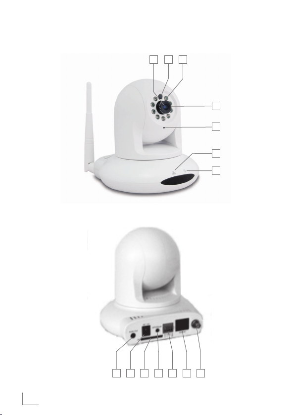
OVERVIEW
A
Camera lens and its cover.
B
Brightness sensor determines the
_______________________________________
brightness of the location of the
camera.
C
Infrared LEDs turn on if the
brightness at this location is not
sufficient (Night Vision mode).
D
Adjustment Ring is used to cor-
rect the image clarity.
E
Microphone.
F
LAN Indicator
on: it means that the LAN con-
nection is activated;
flashes: it means that data
transfer is in progress;
off: it means that the LAN con-
nection is deactivated.
G
Operation LED, turns on when
the camera is in operating.
H
WLAN antenna input socket.
I
Ethernet, it is a socket to con-
nect to the home network with a
LAN cable.
J
DO ... DIR, no function.
K
WPS/Reset, is the button to
record the camera to the router;
(If Router WPS supports, you
can make wireless connection
by pressing and holding the
button on the camera for 3 to 10
seconds while pressing the WPS
buttons on the router concurrently).
in order to reset the camera to its
factory defaults, press and hold
the button for more than 10 seconds; all settings will be deleted.
L
SD, no function.
M
DC 12V, is a connection socket
for the power supply delivered
with the device.
N
Audio Out, no function.
ENGLISH
21
Page 5
ASSEMBLY AND CONNECTION
___________
You can position your GRUNDIG
camera in a suitable place or mount
it onto the wall. Packaging of the
device contains an mounting bracket and fixing elements.
Wall mounting
Notes:
7
Base unit should be fixed and it
should draw the static load.
7
For the wall superstructures,
for example for the wooden or
hollow walls, use appropriate
plugs and screws. For suggestions, please consult your
authorised dealer.
7
Installation place should be
near a power outlet.
7
If the camera is not to be fixed,
the bracket (B) and fixings are
not required. Please start from
step 6.
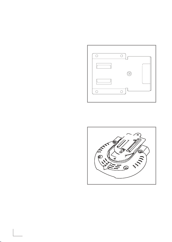
1 Remove the safety screw in the
mounting bracket (A) and loosen
the connection fittings (B).
(A)
2 Insert the fixing (B) to the camera
base and tighten it with the supplied screws (C).
(C)
(B)
(C)
3 Determine the installation place of
the camera and mark the places
where holes will be drilled on the
wall by using the mounting kit.
22
ENGLISH
Page 6
ASSEMBLY AND CONNECTION
___________
4 Drill the holes on the wall and
insert the given plugs into these
holes.
5 Fix the mounting bracket with the
4 supplied screws to the wall.
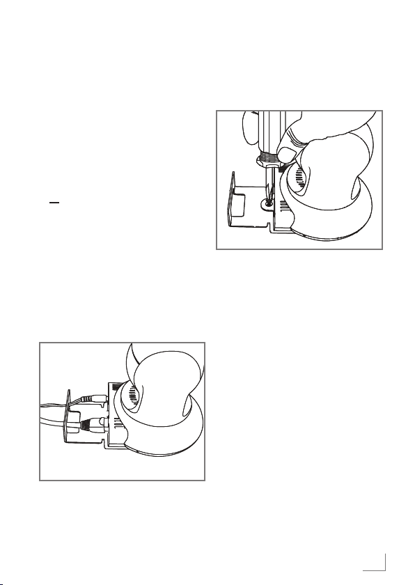
6 For the WLAN operation, screw
the WLAN antenna onto the de-
vice;
or
for LAN operation, connect the
LAN cable to the »Ethernet«
socket.
Note:
7
LAN cable is supplied with the
device.
7 Plug the power cable to the
»DC 12V« socket.
8 Adjust the camera position onto
the mounting bracket and tighten
the safety screw (A).
(A)
9 Plug the DC 12V adaptor to the
wall socket.
– Operation LED lights up soon
and the camera tests the motors
automatically.
10 Connect the LAN cable to an
unused socket on the modem or
router.
Warning:
7
Do not connect the camera to
the LAN input of the television
set. Camera and television
should be connected to each
other over modem or router as
to be on the same network.
Notes:
7
Remove the lens cover.
7
Adjust the camera to the observation position by using the buttons on the remote control.
7
See Adjusting Sharpness section on page 27 to adjust image
sharpness.
ENGLISH
23
Page 7

NETWORK INSTALLATION
__________________
Connect the camera to
the home network and
sign in
In order to ensure that the camera
view is displayed on your TV screen
over the "BABYWATCH" application, your TV and Camera should be
connected to the same network.
You can connect your camera to the
home network with the cabled “LAN”
or wireless “WLAN” connection.
If you are using a cabled “LAN”
connection, please refer to the part
titled "Connection of the camera
with the LAN connection..." in this
section;
If you want to use a wireless
network “WLAN”, follow the instructions described in the section "Operation on the Wireless Network"
"WLAN”.
Warning:
7
Malicious software may penetrate through your personal
local network via Internet and
abuse your audio-visual files.
For such situations, secure your
personal local network. Ensuring the security of the personal
local network is under the responsibility of the user.
Connection of the camera
with a LAN connection
and signing in
Note:
7
Many home networks are Dynamic Networks. If you have
a dynamic network, you must
use a DSL modem that supports
DHCP. If the DHCP server of
the modem does not work, the
camera cannot receive an IP
address.
1 Switch on your television.
2 Select the »Quick Apps« menu
with »@«.
3 Select the »BabyWatch« applica-
tion with »
with »OK«.
– »Help« page will be displayed
Camera Start
∙Plug in the camera adaptor to start set-up.
∙ Power lamp in the front part of the camera will light up. Upper part of the camera will
move after a while.
∙ Attach one end of the LAN cable to the camera and the other to the modem or router to
which the TV is connected.
4 With the »
page.
– Settings page will be displayed.
V
« or »Λ« and confirm
soon which shows how the installation will be made.
.
.
«, exit the »Help«
<
24
ENGLISH
Page 8

NETWORK INSTALLATION
__________________
5 Select the »Search Camera« line
with »
V
« or »Λ« and confirm it
with »OK«.
– After a while, the found camera
icon and IP address will be
displayed.
Note:
7
If camera search fails;
For detailed search, press
»«
(red);
or
if the detailed search fails too,
for Manual IP entry, press »«
(green).
6 Confirm the found camera with
»OK«.
– »Add Camera« menu will be
displayed.
7 In order to display the on-screen
keyboard, press »OK«.
Notes for data entry:
7
Data are entered with the pop-up
keyboard. Select the necessary
V
letters/numbers with »
« or »>« and confirm with
»
<
«, »Λ«,
»OK«.
7
To toggle between uppercase and
lowercase letters, select »Shift«
and confirm with »OK«.
7
Keyboard mode can be changed by
▯« (red).
pressing »
7
You can change the language of
the keyboard/key assignments
▯▯« (green).
with »
7
Last character/number can be deleted with »
▯▯▯▯« (blue).
All entries can be deleted with
»
▯▯▯« (yellow).
7
If the entry of the current line is
completed, close the keyboard
with
»<«.
8 Enter and save the name of the
camera according to your preference as explained in the notes
about data entry.
9 Select the »Password« line with
»
V
« and open the pop-up key-
board with »OK«.
Notes:
7
Camera password has been set
as »admin« as standard factory
default.
7
We recommend you to use a
password belonging to you, see
page 31 “Settings” section.
10 Enter and save »admin« pass-
word as explained in the notes
about data entry.
11 Select the push button »OK«
with »
V
« and confirm with
»OK«.
– “Live streaming” of the camera
is shown on the screen.
Note:
7
If the modem is switched off and
on, IP address of the camera
may change, then repeat the
steps from
5 to 11.
ENGLISH
25
Page 9

NETWORK INSTALLATION
__________________
Registration of the Camera via the Wireless Network “WLAN”
Notes:
7
In order to make the wireless
network “WLAN” settings, first
camera should be connected to
the router over the cabled local
area network.
7
Many home networks are Dynamic Networks. If you have
a dynamic network, you must
use a DSL modem that supports
DHCP. If the DHCP server of the
modem does not work, the camera cannot receive an IP.
1 Switch on your television.
2 Select the »Quick Apps« menu
with »@«.
3 Select the »BabyWatch« applica-
tion with »
with »OK«.
– “Live streaming” of the camera
4 While "live streaming" is shown on
the screen, select the »Settings«
menu with the »
5 Select the »Camera Settings« line
with the »
with »OK«.
– The camera which is connect-
26
V
« or »Λ« and confirm
is shown on the screen.
▯« (red).
V
« or »Λ« and confirm
ed to the network via cabled
“LAN” is displayed on the
screen.
ENGLISH
6 Enter the camera settings with
»OK« and select the »Set Wireless Connection« line with the »
V
or »Λ« and confirm with »OK«.
– After a while, available wireless
networks will be displayed on
the screen.
7 Select the wireless network which
the TV is connected to by using
»
V
«, »Λ« »<« and »>« and con-
firm with »OK« button.
– Network name and entrance
menu with password will be displayed.
8 Select the »Password« line with
the »
V
« or »Λ« and press »OK«.
Enter by using the keyboard the
wireless network password and
close the keyboard with »
9 Select »Yes« push button with »
«.
<
V
and confirm with »OK«.
10 To return to the »Settings« menu,
press »
11 Remove the Network cable.
<
«.
LAN led on the camera will flash
quickly.
– Wireless network connection is
made now.
12 In order to view the “live stream-
ing” of the camera on the screen,
press »
▯« (red).
«
«
Page 10

OPERATION OF THE CAMERA
_____________
Adjusting the Image sharpness
1 Adjust the image sharpness by
using the adjustment ring on the
camera lens.
Selecting the viewing
mode
1 While "live streaming" is dis-
played on the screen, select the
»Application View Mode« menu
with »@«.
– Options:
Full Screen Mode– "live
streaming" is displayed
as "full screen";
Widget Mode – "live
streaming" is displayed
as a small image in the
valid television show.
Dimension and position
of this small image can
be selected;
Notification Mode –
streaming is displayed
only when a movement
is made or a sound is
transmitted.
My Applications – func-
tion ends and the device
returns to the »Quick
Apps« menu or »My Applications« page;
Close – function ends and
the device returns to the
current television show.
2 Select the desired mode with »
« and confirm with »OK«.
or »
>
<
Changing the camera
angle
Camera angle can be set to the Full
Screen Mode for the "Live streaming".
1 Select the »Application View
Mode« with »@«.
2 Select the »Full Screen Mode«
with »
« or »>« and confirm with
<
»OK«.
3 Adjust the desired camera angle
with »
V
«, »Λ«, »<« or »>«.
Note:
7
The camera can be reset to the
starting position (90° horizontal/vertical). To do this:
select the »Settings« menu with
▯« (red), select the »Camera
»
settings« row with »
and confirm with »
OK
Press»
»Reset Position« row with »
or »
Close the settings menu with
»
streaming” with »
« again, select the
Λ
« and confirm with »OK«.
« and switch to the “live
<
V
« or »Λ«
OK
«.
▯« (red).
V
«
«
ENGLISH
27
Page 11

OPERATION OF THE CAMERA
_____________
Selecting the position of
the inset picture
In the Widget mode you can select
the position at which the inset image
is displayed on the screen.
1 Select the »Application View
Mode« with »@«.
2 Select the »Widget Mode« with
»
« or »>« and confirm with
<
»OK«.
3 Select the desired location with
»
V
«, »Λ«, »<« or »>«.
Selecting the dimension
of the inset picture
You can select the dimension of the
inset image to be displayed on the
screen from the Widget mode.
1 Select the »Application View
Mode« with »@«.
2 Select the »Widget Mode« with
»
« or »>« and confirm with
<
»OK«.
3 To decrease the size of the inset
image press »
increase its size press »
(blue).
▯« (red) and to
▯▯▯▯«
Turn the picture
1 While “live streaming” is shown
on the screen, turn the picture
vertically with »
Turn the picture
– vertically
▯« (green).
– horizon-
tally
1 While “live streaming” is shown
on the screen, turn the picture
horizontally with »
▯« (yellow).
End the Babywatch function
1 Select the »Application View
Mode« with »@«.
2 Select »Close« with the »
»
« and confirm with »OK«.
>
<
« or
28
ENGLISH
Page 12

SETTINGS
_________________________________________
Notification mode options
Deactivation/Activation of the
Motion Detection Function
1 While “live streaming” is shown
on the screen, select the »Settings« menu with »
2 Select the »Detection Settings«
line with
V
with »OK«.
– Menu is displayed.
3 If the notification should be made
only by sound, select the »x«
character in the box next to the
»Enable Motion Detection« with
V
« or »Λ« and delete it with
»OK«.
– Motion detection is disabled.
Note:
7
In order to restart the video
monitoring, select the box with
»
V
« or »Λ« and adjust the »x«
character with »OK«.
Motion detection settings
1 Select »Ambient Light« with »V«
Λ
« and select either »Light-
or »
ness« or »Darkness« with »
« depending on the condition
»
>
of the environment.
2 Select the »Movement Sensitivity
(%)« line with the »
button and adjust the sensitivity
« or »>« .
with »
<
▯« (red).
« or »Λ« and confirm
« or
<
V
« or »Λ«
3 Select the »Movement Rate (%)«
V
line with the »
« or »Λ« button
and adjust the movement rate
« or »>«.
with »
<
Note:
7
Movement rate is the proportion
of the size of the moving object
to the movement area. When
this value is selected higher,
detection will be enabled upon
movement of large objects.
When this value is selected
lower, detection will be enabled
upon movement of small objects
4 To adjust the area of detection,
select »Movement Window« line
with »
V
« or »Λ« button and
confirm with »OK« button.
By using »
V
«, »Λ«, »<« or »>«
button, select the position of the
detection window.
With »
▯« (red), »▯▯« (green),
»
▯▯▯« (yellow) and »▯▯▯▯«
(blue) buttons adjust the dimensions of the detection window.
To end the setting process, press
»
« button.
<
ENGLISH
29
Page 13

SETTINGS
_________________________________________
Deactivation/Activation of
the Sound Detection
1 If the notification should be only
made by video monitoring, select
the »x« character in the box next
to the »Enable Sound Detection«
with
V
« or »Λ« and delete it with
»OK«.
– Sound detection is disabled.
Note:
7
In order to restart the sound
detection, select the box with
»
V
« or »Λ« and adjust the »x«
character with »OK«.
Adjusting the sound sensitivity
1 Select the line »Sound Sensitivity«
with »
V
« or »Λ«.
2 Select the sensitivity level with
»
« or »>«.
<
Setting the period of time
the notification will be dis-
played on the screen
1 Select the line »Event Display
Time« line with »
2 Select the desired option with »
or »
«.
>
V
« or »Λ«.
<
Saving the Settings
1 Select the push button »OK« with
»
V
« or »Λ« and confirm with
»OK«.
Note:
7
If the changes will not be
saved, select the push button
»CANCEL« with »
V
« or »Λ«
and confirm with »OK«.
Displaying and reporting
notifications
“Live image” is displayed subject to
the selected setting and the “action”
in the room being monitored. In that
case, a message will be displayed:
– High sound detected.
– Movement detected.
«
30
ENGLISH
Page 14

SETTINGS
_________________________________________
Changing the password
1 While "live streaming" is shown
on the screen, select the »Settings« menu with »
2 Select the »Camera Settings« line
with »
V
« or »Λ« and confirm
with »OK«.
– Connected camera is viewed.
3 Go to the camera settings with
»OK«.
4 Select the »Change Password«
line with »
with »OK«.
5 Press »OK« and enter and save
the current password using the
keyboard.
6 Select the »New Password« line
with »
V
« or »Λ« and confirm
with »OK«.
7 Enter a new password (max. 22
characters) and confirm it.
8 Enter the »Retype Password« line
with »
V
« or »Λ« and confirm
with »OK«.
9 Enter the new password again
and confirm it.
10 Select the push button
»Change« with »
adjust it with »OK«.
▯« (red).
V
« or »Λ« and confirm
V
« or »Λ« and
Note:
7
If the new password will not be
saved, select the push button
»Cancel« with »
V
« or »Λ« and
confirm with »OK«.
Selecting the image transmission type
1 While "live streaming" is shown
on the screen, select the »Settings« menu with »
2 Select the »Video Type« line with
»
V
« or »Λ«.
3 Select the desired »mjpeg« or
»rtsp« image transmission type
with the »
– »mjpeg« – Video codec with
compressed image (recommended for the WLAN connected works);
– »rtsp« – Real time transmission
and minimum compression
video codec (recommended for
the LAN connected works).
Note:
7
If you face problems with »rtsp«
on wireless connection, change
your setting to »mjpeg«.
« or »>«.
<
▯« (red).
ENGLISH
31
Page 15

SETTINGS
_________________________________________
Selecting the background
image for the menu
1 While "live streaming" is shown
on the screen, select the »Settings« menu with »
2 Select the »Theme« line with »
or »
Λ
«.
▯« (red) button.
V
«
3 Select the desired background
image with »
« or »>«.
<
Searching for the other
cameras in the local network
1 While "live streaming" is shown
on the screen, select the »Settings« menu with »
2 Select the »Search Camera« line
V
« or »Λ« and confirm it
with »
with »OK«.
– After a while, icons of the
found cameras and IP address
will be displayed.
▯« (red).
Selecting other cameras
in the local network
1 While "live streaming" is
displayed on the screen, select
the »Settings« menu with the »
(red).
2 Select the »Camera Settings« line
with »
V
« or »Λ«.
– Icons of all of the cameras
connected to TV and their IP
addresses will be displayed.
3 Select the camera which you want
V
to view with »
« and go to the camera settings
»
>
«, »Λ«, »<« or
with »OK«.
4 Select the »Start Stream« line with
»
V
« or »Λ« and confirm with
»OK«.
– “Live streaming” of the camera
is shown on the screen.
▯«
32
ENGLISH
Page 16

INFORMATION
_________________________________
Service notes for the authorized sellers
BabyWatch set may only be
operated with the power cable/
adaptor supplied with the set.
This product meets the following EU
requirements:
Energy consumption values and
classes were determined in accordance with specifications 2009/642,
2010/1062 and also guidelines
EN62087 and EN62301 pursuant
to directives 2009/125/EC and
2010/30/EU from the European
Union.
Grundig declares that this product
complies with the EU Regulation
1999/5/EC and 2011/65/EU.
Complete and accurate text of the
Declaration of Conformity (DOC)
can be accessed via the GRUNDIG
page on www.grundig.com/download/doc.
This device can be used in the
following countries without any
limitations.
AT BE BG CH CY CZ DE DK
EE ES FI FR GB GR HU IE
IS IT LI LT LU LV MT NL
NO PL PT RO SE SI SK TR
This device can also be used in the
countries outside Europe.
Please be advised of the following limitations for the following
countries:
For the customers in
France:
Outdoor use of the device is limited
with 10 mW EIRP at 2454 - 2483.5
MHz frequency range. Use for the
military radio positions.
Re-regulation of the 2.4 GHz frequency was put into effect in recent
years in order to allow the current
less stringent regulation. Transition
to the full implementation has been
planned as 2012
For the customers in Italy:
For the private uses apart from the
personal houses , there is general
approval requirement for public use.
For the customers in Norway:
This subparagraph is not valid for
the geographical area up to 20 km
from the center of NyÅlesund.
For the customers in Russia:
1. FHSS modulated SRD
7
Maximum 2.5 mW EIRP.
ENGLISH
33
Page 17

INFORMATION
7
Maximum 100 mW EIRP. For the
_________________________________
collection of and compliance with
the telemetry data and the calculation systems, the device is allowed to be used in the outdoors
where it is located (at the same
height) without any limitation.
In the similar practices which are
listed above, the location (height)
of the device should not exceed
10 m.
7
For indoors, it is maximum 100
mW EIRP.
2. Other broadband modulation systems such as SRD with
DSSS and FHSS
7
Maximum average value EIRP,
signal density at 2 mW/MHz.
Maximum 100 mW EIRP.
7
Maximum 100 mW EIRP. For the
collection of and compliance with
the telemetry data and the security systems, the device is allowed
to be used in the outdoors where
it is located (at the same height)
without any limitation.
7
Maximum average value EIRP,
signal density at 10 mW/MHz.
Maximum 100 mW EIRP Indoors.
For the customers in
Ukraine:
EIRP ≤100 mW with integrated
antenna and amplification factor up
to 6 dBi
ENGLISH
34
Environmental note
This product has
been made from
high-quality parts
and materials which
can be re-used and
recycled.
Therefore, do not throw the product
away with normal household waste
at the end of its life. It should be
disposed of in a collection point for
recycling electrical and electronic
devices. This information is indicated
by a symbol on the product, in its
user manual and on its packaging.
For information about the collection
points, please refer to your municipality officials.
By recycling used devices, you
make a significant contribution to
the protection of our environment.
Technical data
Power supply:
DC 12 V, 2 A
Dimensions and weight:
W x H x D: 105 x 123 x 107
mm
Weight: approx. 305 g
We reserve the right to make technical and optical modifications.
 Loading...