

Kundendienst/Werkstätten:
0180/52318-52*
0180/52318-46*
Telefon:
Fax:
*0,12€/Min. über Arcor
Mo.-Fr. 8.00-18.00 Uhr
HiFi Service Manual
(Reparatur / Repair)
Fine Arts Audion
RCD 8300 GLK0650
LSP 2 GNK0752
LSP 3 GNK0852
Zusätzlich erforderliche Unterlagen für den Komplettservice
Additionally required Service Documents for the Complete Service
Service
Manual
Sicherheit
Safety
Materialnr./Part No.
720108000000
Dieses Service Manual ist nur in Datenform verfügbar / This Service Manual is only available as data
Änderungen vorbehalten / Subject to alteration
Made by GRUNDIG in Germany • http://www.grundig.com
H-S42 • 0403 • 720107726000
Grundig Service
NUR FÜR INTERNEN GEBRAUCH
FOR INTERNAL USE ONLY
Technik:
TV
TV
SAT
VCR/LiveCam
HiFi/Audio
Car Audio
Telekommunikation
Planatron
Ersatzteil-Verkauf: Mo.-Fr. 8.00-19.00 Uhr
Fax:
(8.00-22.00 Uhr)
Telefon: 0180/52318-40*
Hotline Deutschland…
…Mo.-Fr. 8.00-18.00 Uhr
0180/52318-41*
0180/52318-49*
0180/52318-48*
0180/52318-42*
0180/52318-43*
0180/52318-44*
0180/52318-45*
0180/52318-51*
0180/52318-99*
0180/52318-50*Fax:
GRUNDIG Service Fine Arts Audion
Es gelten die Vorschriften und Sicherheitshinweise gemäß dem Service Manual "Sicherheit",
Materialnummer 720108000000, sowie zusätzlich die eventuell abweichenden, landesspezifischen Vorschriften!
Inhaltsverzeichnis
Seite
Allgemeiner Teil ............................... 1-2 … 1-13
Servicehinweise ........................................................................... 1-2
Ausbauhinweise RCD 8300 ......................................................... 1-3
Ausbauhinweise LSP 2 ................................................................ 1-7
Ausbauhinweise LSP 3 ................................................................ 1-9
Beschreibung WLM-Modul Tx4 (Datentransceiver) ................... 1-11
Servicefunktionen ............................ 2-1 … 2-17
RCD 8300 .................................................................................... 2-1
LSP 2 / LSP 3 ............................................................................ 2-10
PR 1 ........................................................................................... 2-13
Abgleichvorschriften ......................... 3-1 … 3-2
RCD 8300 .................................................................................... 3-1
The regulations and safety instructions shall be
valid as provided by the "Safety" Service Manual,
part number 720108000000, as well as the respective national deviations!
Table of Contents
Page
General Section ................................ 1-2 … 1-13
Service Instructions ...................................................................... 1-2
Disassembling Instructions RCD 8300 ........................................ 1-3
Disassembling Instructions LSP 2 ............................................... 1-7
Disassembling Instructions LSP 3 ............................................... 1-9
Description WLM-Modul Tx4 (Data transceiver) ........................ 1-11
Service Functions ............................ 2-1 … 2-17
RCD 8300 .................................................................................... 2-1
LSP 2 / LSP 3 ............................................................................ 2-10
PR 1 ........................................................................................... 2-13
Adjustment Procedures..................... 3-1 … 3-2
RCD 8300 .................................................................................... 3-1
Schaltpläne und
Platinenabbildungen ........................ 4-1 … 4-54
RCD 8300 .................................................................................... 4-1
LSP 2 ......................................................................................... 4-25
LSP 3 ......................................................................................... 4-40
Explosionszeichnungen
und Ersatzteillisten ............................ 5-1 … 5-9
RCD 8300 .................................................................................... 5-1
LSP 2 ........................................................................................... 5-6
LSP 3 ........................................................................................... 5-8
Servicehinweise
Achtung: ESD-Vorschriften beachten
Vor Öffnen des Gehäuses Netzstecker ziehen.
Leitungsverlegung
Bevor Sie die Leitungen und insbesondere die Masseleitungen lösen,
muss die Leitungsverlegung zu den einzelnen Baugruppen beachtet
werden.
Nach erfolgter Reparatur ist es notwendig, die Leitungsführung wieder
in den werkseitigen Zustand zu versetzen um evtl. spätere Ausfälle
oder Störungen zu vermeiden.
Wichtige Masseverbindungen!
Beim Zusammenbau des Gerätes ist darauf zu achten, dass die
Masseverbindungen zwischen den einzelnen Platinen und dem Rahmen sowie dem Laufwerk und dem Rahmen gewährleistet sind.
Durchführen von Messungen
Bei Messungen mit dem Oszilloskop an Halbleitern sollten Sie nur
Tastköpfe mit 10:1 - Teiler verwenden. Außerdem ist zu beachten,
dass nach vorheriger Messung mit AC-Kopplung der Koppelkondensator des Oszilloskops aufgeladen sein kann. Durch die Entladung
über das Messobjekt können diese Bauteile beschädigt werden.
Messwerte und Oszillogramme
Bei den in den Schaltplänen und Oszillogrammen angegebenen
Messwerten handelt es sich um Näherungswerte!
Circuit Diagrams and
Layout of the PCBs .......................... 4-1 … 4-54
RCD 8300 .................................................................................... 4-1
LSP 2 ......................................................................................... 4-25
LSP 3 ......................................................................................... 4-40
Exploded Views and
Spare Parts Lists ................................ 5-1 … 5-9
RCD 8300 .................................................................................... 5-1
LSP 2 ........................................................................................... 5-6
LSP 3 ........................................................................................... 5-8
Service Instructions
Attention: Observe the ESD safety regulations
Disconnect the mains plug before opening the set.
Wiring
Before disconnecting any leads and especially the earth connecting
leads observe the way they are routed to the individual assemblies.
On completion of the repairs the leads must be laid out as originally
fitted at the factory to avoid later failures or disturbances.
Important: Ground Connections!
When reassembling the set it is essential to observe that the ground
connections between the individual circuit boards and the frame as
well as between the Drive Mechanism and the frame are in good order.
Carrying out Measurements
When making measurements on semi-conductors with an oscilloscope, ensure that the test probe is set to 10:1 dividing factor. Further,
please note that if the previous measurement is made on AC input, the
coupling capacitor in the oscilloscope will be charged. Discharge via
the item being checked can damage components.
Measured Values and Oscillograms
The measured values given in the circuit diagrams and oscillograms
are approximates!
1 - 2
GRUNDIG Service Fine Arts Audion
Ausbauhinweise RCD 8300
Leitungsverlegung
Bevor Sie die Leitungen lösen ist die Leitungsverlegung zu den
einzelnen Baugruppen zu beachten.
Nach erfolgter Reparatur ist es notwendig, die Leitungsführung wieder
in den werkseitigen Zustand zu versetzen um evtl. spätere Ausfälle
oder Störungen zu vermeiden.
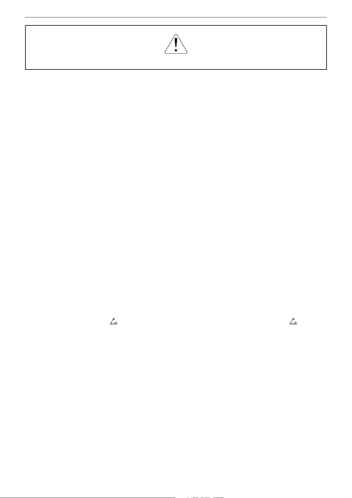
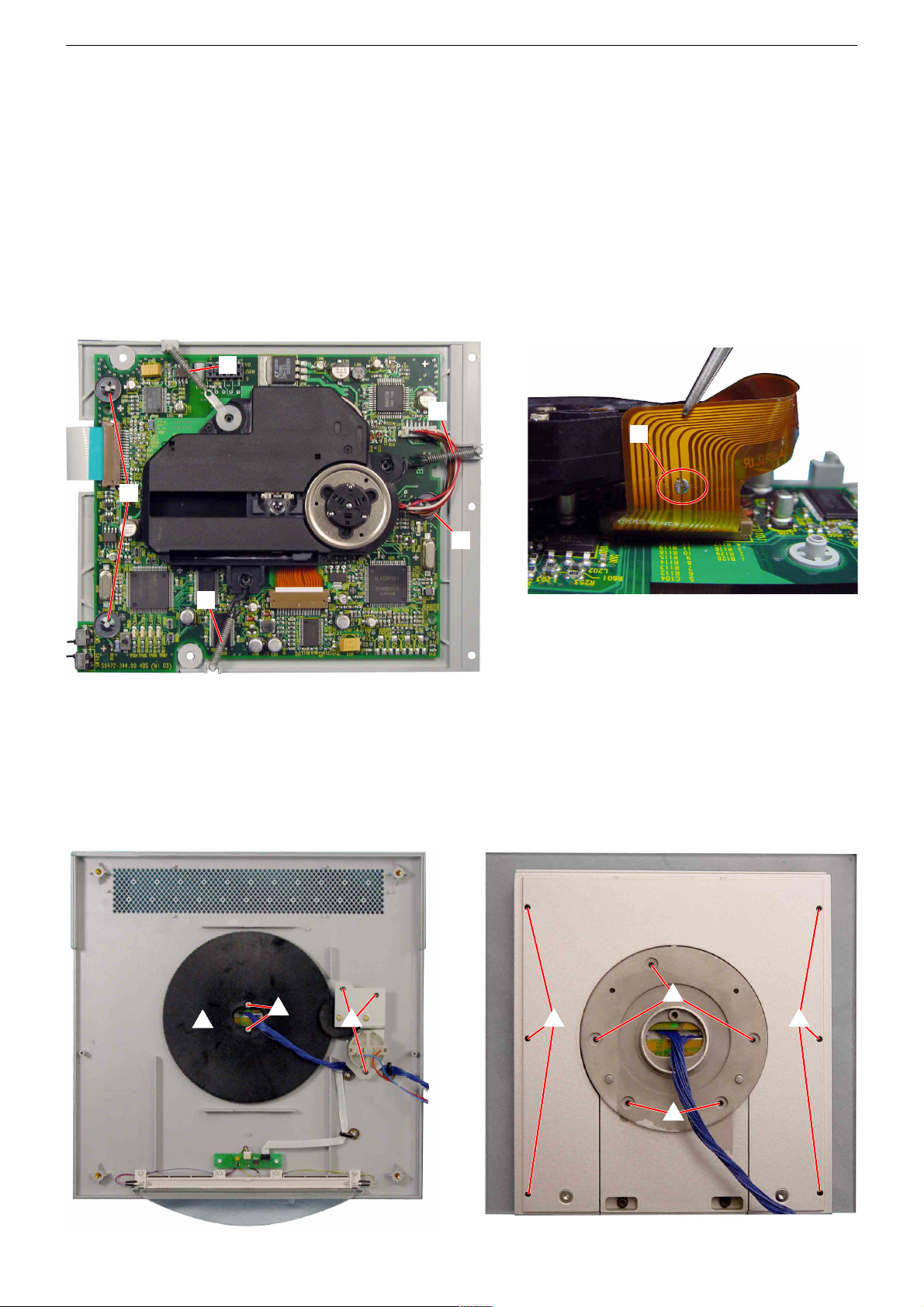
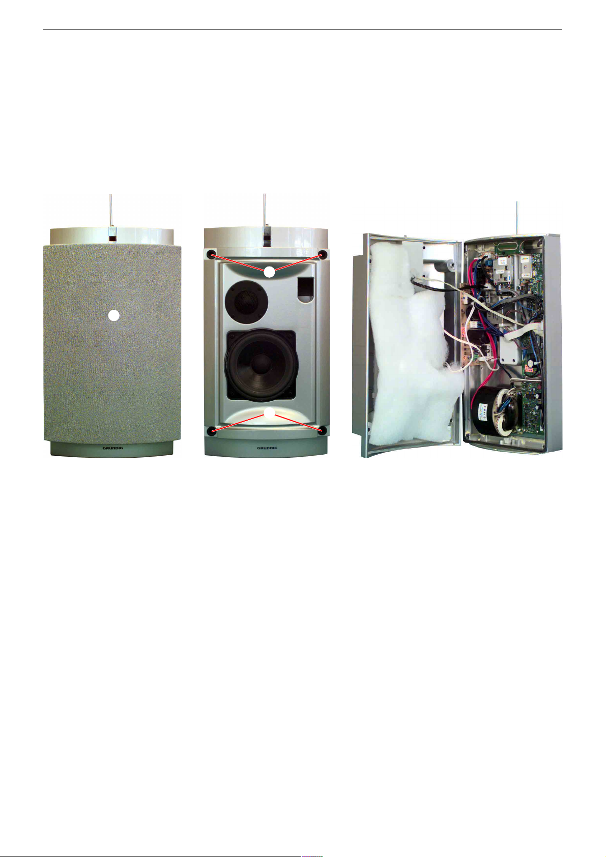
1. Gehäuse öffnen
- RCD 8300 mit der Bodenplatte nach oben auf eine weiche, kratzfreie Unterlage legen.
- 4 Schrauben A und 2 Schrauben B (Fig. 1) herausdrehen.
- RCD 8300 vorsichtig umdrehen und Gehäuseoberteil zur Seite
nach links umklappen (Achtung: Kurze Leitungen) Leitungen zum
Gehäuseoberteil bei Bedarf abziehen.
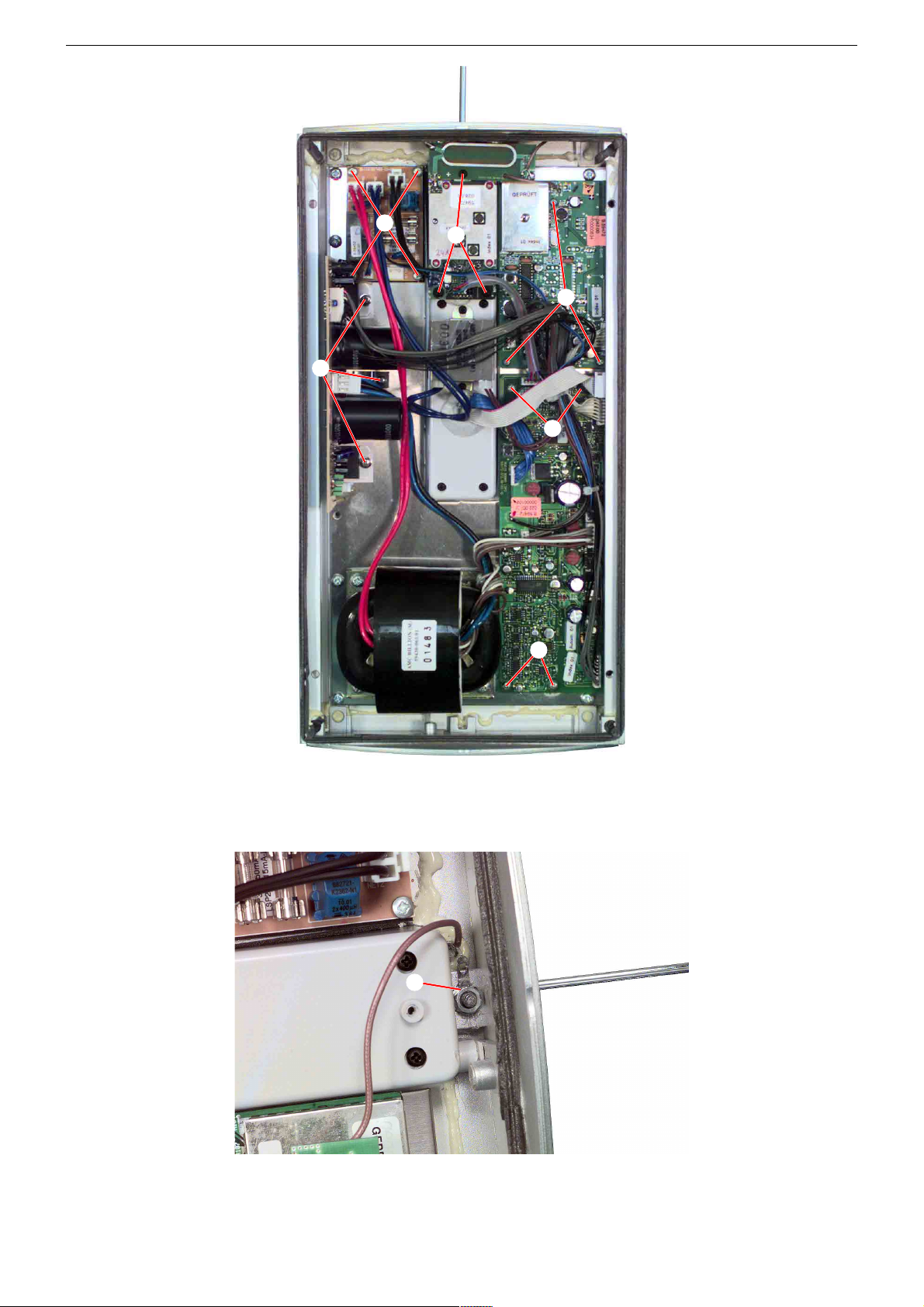
2. CD-Laufwerk ausbauen
- Gehäuse öffnen (Pkt. 1).
- CD Schublade öffnen.
Alternativ: 3 Schrauben H (Fig. 1) herausschrauben und die CDBlende G abnehmen.
- 3 Schrauben D und 3 Schrauben E herausschrauben und die
Blenden C nach vorne abnehmen (Fig. 2).
- 4 Schrauben F herausschrauben und Laufwerk herausnehmen
(Steckverbinder unter dem Laufwerk bei Bedarf öffnen).
3. Steuer-Platte I ausbauen
- CD-Laufwerk ausbauen (Pkt. 2).
- 3 Schrauben J (Fig. 3) herausschrauben.
- Steuer-Platte herausnehmen (Steckverbinder bei Bedarf öffnen).
Disassembly Instructions RCD 8300
Wiring
Before disconnecting any leads observe the way they are routed to the
individual assemblies.
On completion of the repairs the leads must be laid out as originally
fitted at the factory to avoid later failures or disturbances.
1. Disassembling the case
- Place the RCD 8300 upside down on a soft scratch-resistant
surface.
- Undo the 4 screws A and the 2 screws B (Fig. 1).
- Carefully turn around the RCD 8300 then place the cabinet's top part
to the left side (Attention: Short Wires) If necessary disconnect the
wires to the cabinet´s top.
2. Removing the CD Drive
- Disassemble the case (para 1).
- Open the CD Tray.
Alternative: Undo 3 screws H (Fig. 1) and remove the CD Cover G.
- Undo 3 screws D and 3 screws E and take off the covers C
towards the front.
- Undo 4 screws F and take out the CD Drive (open connectors
beneath the Drive if necessary).
3. Removing the Control Board I
- Remove the CD Drive (para 2).
- Undo 3 screws J (Fig. 3).
- Remove the Control Board (open connectors if necessary).
I
J
A
B
A
H
Fig. 1
G
L
M
K
M
C
D
F
E
C
Fig. 2
Fig. 3
M
1 - 3
GRUNDIG Service Fine Arts Audion
4. Signal-Platte K ausbauen
- CD-Laufwerk ausbauen (Pkt. 2).
- 2 Schrauben L und 6 Schrauben M (Fig. 3) herausschrauben.
- Die Signal-Platte zusammen mit den Antennenbuchsen herausnehmen (Steckverbinder bei Bedarf öffnen).
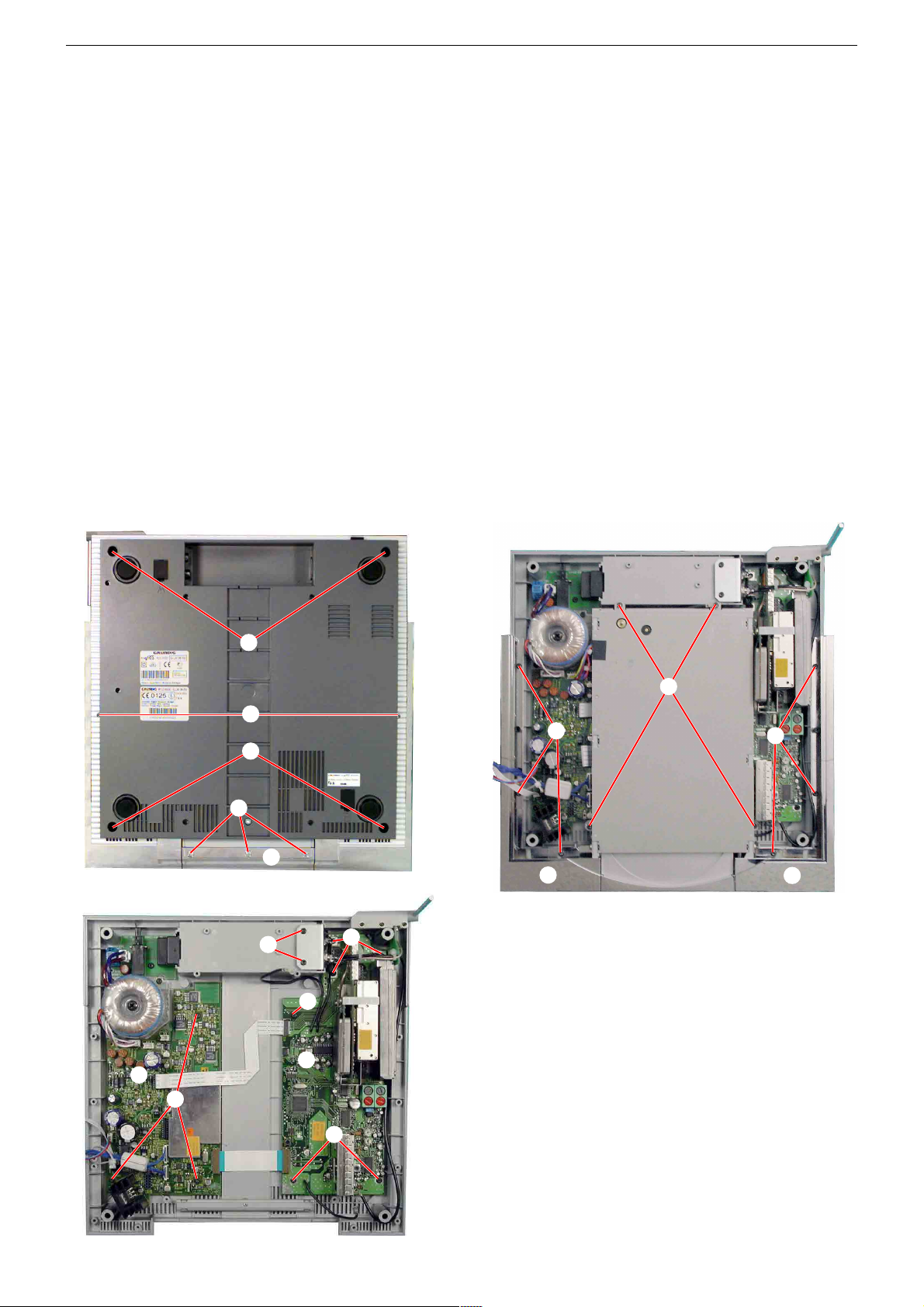
5. CD-Laufwerk zerlegen
- CD-Laufwerk ausbauen (Pkt. 2).
- 2 Schrauben A und 4 Schrauben B (Fig. 4, 5) herausschrauben.
- Abdeckung C abnehmen.
- Schraube D herausschrauben und den Hebel E aus der Rastung
F ausrasten (Fig. 6).
- Schublade nach vorne schieben.
- Schraube G (Fig. 7) herausschrauben, Stange H ausrasten und
nach hinten herausziehen.
- Schublade herausnehmen (Steckverbinder bei Bedarf öffnen).
6. Motoreinheit ausbauen
- CD-Laufwerk ausbauen (Pkt. 2).
- 2 Schrauben A und 4 Schrauben B (Fig. 4, 5) herausschrauben.
- Abdeckung C abnehmen.
- Schraube D herausschrauben und den Hebel E aus der Rastung
F ausrasten (Fig. 6).
- Schublade nach vorne schieben.
- 3 Schrauben I (Fig. 6) herausschrauben und Motoreinheit herausnehmen.
4. Removing the Signal Board K
- Remove the CD Drive (para 2).
- Undo 2 screws L and 6 screws M (Fig. 3).
- Remove the Signal Board together with the antenna sockets (open
connectors if necessary).
5. Disassembling the CD Drive
- Remove the CD Drive (para 2).
- Undo 2 screws A and 4 screws B (Fig. 4, 5).
- Take off the cover C.
- Undo screw D and unhinge lever E from the hinge F (Fig. 6).
- Pull the CD tray to the front.
- Undo screw G (Fig. 7), unhinge the bar H and pull it out to the rear.
- Remove the CD Tray (open connectors if necessary).
6. Removing the Motor Unit
- Remove the CD Drive (para 2).
- Undo 2 screws A and 4 screws B (Fig. 4, 5).
- Take off the cover C.
- Undo screw D and unhinge lever E from the hinge F (Fig. 6).
- Pull the CD Tray to the front.
- Undo 3 screws I (Fig. 6) and take out the Motor Unit.
A
Fig. 4
C
Fig. 6
B
F
E
C
A
B
Fig. 5
H
I
G
D
Fig. 7
J
K
Fig. 8
1 - 4
GRUNDIG Service Fine Arts Audion
7. CD-Laufwerk-Einheit ausbauen (Fig. 8)
- CD Schublade öffnen.
- RCD 8300 mit der Bodenplatte nach oben auf eine weiche, kratzfreie Unterlage legen.
- 3 Schrauben
- 2 Schrauben
ausnehmen.
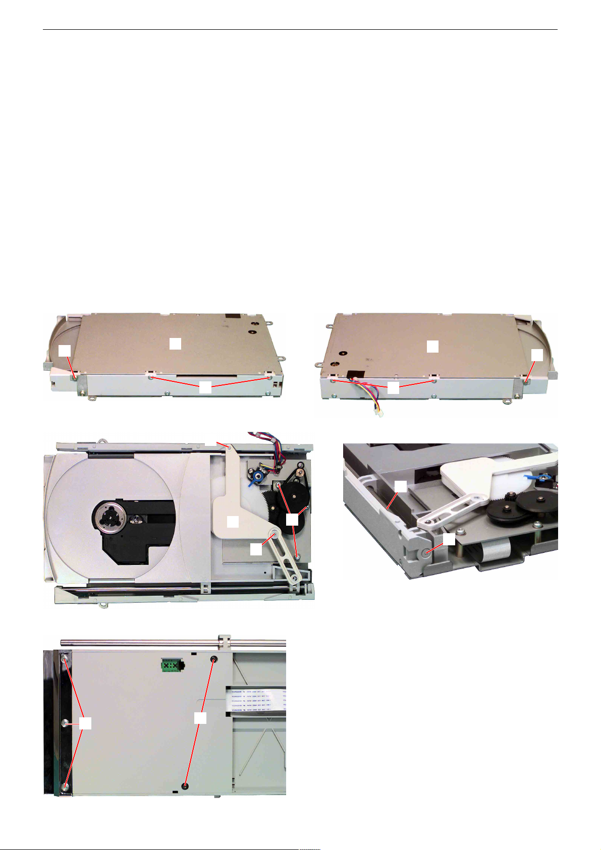
8. Pick-Up-Einheit ausbauen (Fig. 9)
- CD-Laufwerk-Einheit ausbauen (Pkt. 7)
- 3 Federn L aushängen (Fig. 9) und Pick-Up-Einheit abnehmen.
Achtung: Vor dem Abziehen der Flexprintleitung die Schutzlötstelle M (Fig. 10) zulöten! Die Laserdiode kann sonst durch
statische Aufladung zerstört werden.
9. CD-Leiterplatte ausbauen
- Pick-Up-Einheit ausbauen (Pkt. 8).
- 3 Wellensicherungen N (Fig. 9) ausrasten und Leiterplatte abnehmen.
J herausschrauben und die Abdeckung abnehmen.
K herausschrauben und die Laufwerk-Einheit her-
L
N
L
7. Removing the CD Drive Unit (Fig. 8)
- Open the CD Tray.
- RCD 8300 mit der Bodenplatte nach oben auf eine weiche, kratzfreie Unterlage legen.
- Undo 3 screws
- Undo 2 screws
8. Removing the Pick Up Unit (Fig. 9)
- Remove the CD Drive Unit (para 7).
- Unhinge 3 springs L (Fig. 9) and take off the Pick Up Unit.
Caution: Before unplugging the flexprint close the protective
solder joint M (Fig. 10)! The Laser diode may otherwise be
destroyed by static electricity.
9. Removing the CD-PCB
- Remove the Pick Up Unit (para 8).
- Unlock 3 Spindle Lock Washers N (Fig. 9) and remove the PCB
J and take off the cover.
K and take out the CD Drive Unit.
M
L
Fig. 9
10. Display ausbauen (Fig. 11)
- Gehäuse öffnen (Pkt. 1).
- 3 Schrauben a herausschrauben und Motoreinheit abnehmen.
- 2 Schrauben b herausschrauben und Zahnrad c abnehmen.
- Display nach außen abziehen.
N
Fig. 10
10. Removing the Display (Fig. 11)
- Disassemble the case (para 1).
- Undo 3 screws a and remove the motor unit.
- Undo 2 screws b and remove the toothed wheel c.
- Pull out the Display outwards.
c
Fig. 11
b
a
f
d d
f
Fig. 12
1 - 5
GRUNDIG Service Fine Arts Audion
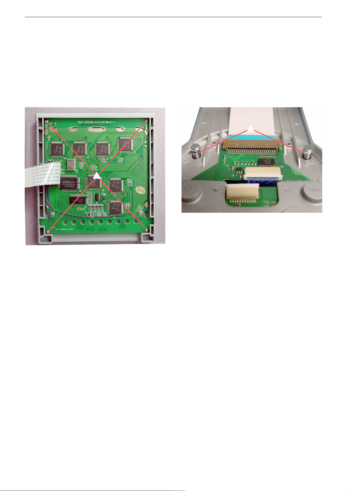
11. Display zerlegen
- Display ausbauen (Pkt. 10).
- 6 Schrauben d (Fig. 12) herausschrauben und das DisplayGehäuse öffnen (Steckverbinder bei Bedarf öffnen).
- 4 Schrauben
platte entnehmen.
12. Tastatur zerlegen
- Display ausbauen (Pkt. 10).
- 5 Schrauben
Gehäuse öffnen (Achtung auf die beiden Bolzen mit Federn g
(Fig. 14); Steckverbinder bei Bedarf öffnen).
e (Fig. 13) herausschrauben und Display-Leiter-
f (Fig. 12) herausschrauben und das Tastatur-
e
11. Disassembling the Display
- Remove the Display (para 10).
- Undo 6 screws d (Fig. 12) and open the display housing (open
connectors if necessary).
- Undo 4 screws
11. Disassembling the Keyboard
- Remove the Display (para 10).
- Undo 5 screws
out for the 2 bolts with springs g (Fig. 14); open connectors if
necessary).
e (Fig. 13) and remove the Display PCB.
f (Fig. 12) and open the keyboard housing (watch
g
Fig. 13
Fig. 14
1 - 6
GRUNDIG Service Fine Arts Audion
Ausbauhinweise LSP 2
Leitungsverlegung
Bevor Sie die Leitungen lösen ist die Leitungsverlegung zu den
einzelnen Baugruppen zu beachten.
Nach erfolgter Reparatur ist es notwendig, die Leitungsführung wieder
in den werkseitigen Zustand zu versetzen um evtl. spätere Ausfälle
oder Störungen zu vermeiden.
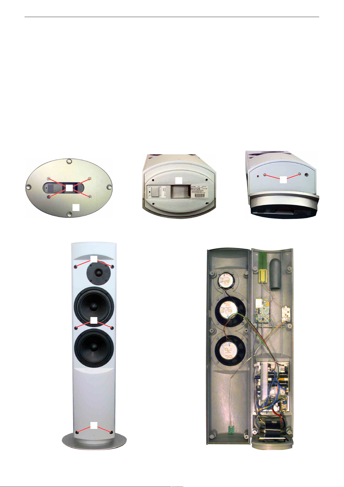
1. Öffnen des Gehäuses
- Die Abdeckungen abnehmen.
- 4 Schrauben 1 herausschrauben und Platte 2 abnehmen (Fig. 1).
- Boden 3 vorsichtig wegbiegen und 2 Schrauben 4 herausschrau-
ben (Fig. 2 und 3).
- Die 6 Gummistopfen 5 herausziehen und die darunter befindlichen
Schrauben herausschrauben (Fig. 4).
- Gehäuse aufklappen, Steckverbinder bei Bedarf öffnen (Fig. 5).
- Dämm-Material herausnehmen.
1
Disassembly Instructions LSP 2
Wiring
Before disconnecting any leads observe the way they are routed to the
individual assemblies.
On completion of the repairs the leads must be laid out as originally
fitted at the factory to avoid later failures or disturbances.
1. Opening the Cabinet
- Take off the covers.
- Undo 4 screws 1 and remove the plate 2 (Fig. 1).
- Carefully bent away the socket 3 and undo 2 screws 4 (Fig. 2
and 3).
- Pull out 6 rubber stoppers 5 and undo the screws beneath them
(Fig. 4).
- Unfold the cabinet, open connectors if necessary (Fig. 5).
- Remove the Sound proofing.
3
4
2
Fig. 1 Fig. 2 Fig. 3
5
5
5
Fig. 4 Fig. 5
1 - 7
GRUNDIG Service Fine Arts Audion
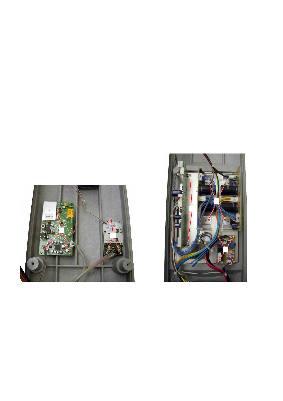
2. Datenfunk-Modul ausbauen (Fig. 6)
- Gehäuse öffnen (Pkt. 1).
- 3 Schrauben 6 herausschrauben.
- Datenfunk-Modul herausnehmen (Steckverbinder bei Bedarf öffnen
und Antennen-Leitung ablöten).
3. Empfänger-Platte ausbauen (Fig. 6)
- Gehäuse öffnen (Pkt. 1).
- 3 Schrauben 7 herausschrauben.
- Empfänger-Platte herausnehmen (Steckverbinder bei Bedarf öffnen und Antennen-Leitung ablöten).
4. NF-Endstufen-Platten ausbauen (Fig. 7)
- Gehäuse öffnen (Pkt. 1).
- Je 2 Schrauben 8 herausschrauben.
- NF-Endstufen-Platten herausnehmen (Steckverbinder bei Bedarf
öffnen).
5. Audio-Platte ausbauen (Fig. 7)
- Gehäuse öffnen (Pkt. 1).
- 2 Schrauben 9 herausschrauben.
- Audio-Platte herausnehmen (Steckverbinder bei Bedarf öffnen).
6. Netz-Anschluss-Platte ausbauen (Fig. 7)
- Gehäuse öffnen (Pkt. 1).
- 4 Schrauben 0 herausschrauben.
- Netz-Anschluss-Platte herausnehmen (Steckverbinder bei Bedarf
öffnen).
2. Removing the Data Radio Module (Fig. 6)
- Open the cabinet (para 1).
- Undo 3 screws 6.
- Remove the Data Radio Module, open connectors if necessary and
unsolder antenna wire.
3. Removing the Receiver Board (Fig. 6)
- Open the cabinet (para 1).
- Undo 3 screws 7.
- Remove the Receiver Board, open connectors if necessary and
unsolder antenna wire.
4. Removing the AF Amplifier Boards (Fig. 7)
- Open the cabinet (para 1).
- Undo each 2 screws 8.
- Remove the AF Amplifier Boards, open connectors if necessary.
5. Removing the Audio Board (Fig. 7)
- Open the cabinet (para 1).
- Undo 2 screws 9.
- Remove the Audio Board, open connectors if necessary.
6. Removing the Mains Connection Board (Fig. 7)
- Open the cabinet (para 1).
- Undo 4 screws 0.
- Remove the Mains Connection Board, open connectors if necessary.
7
6
Fig. 6 Fig. 7
8
9
0
1 - 8
GRUNDIG Service Fine Arts Audion
Ausbauhinweise LSP 3
Leitungsverlegung
Bevor Sie die Leitungen lösen ist die Leitungsverlegung zu den
einzelnen Baugruppen zu beachten.
Nach erfolgter Reparatur ist es notwendig, die Leitungsführung wieder
in den werkseitigen Zustand zu versetzen um evtl. spätere Ausfälle
oder Störungen zu vermeiden.
1. Öffnen des Gehäuses
- Die Abdeckung 1 abnehmen (Fig. 1).
- Die 4 Gummistopfen 2 herausziehen und die darunter befindlichen
Schrauben herausschrauben (Fig. 2).
- Gehäuse aufklappen, Steckverbinder bei Bedarf öffnen (Fig. 3).
2
1
Disassembly Instructions LSP 3
Wiring
Before disconnecting any leads observe the way they are routed to the
individual assemblies.
On completion of the repairs the leads must be laid out as originally
fitted at the factory to avoid later failures or disturbances.
1. Opening the Cabinet
- Take off the cover 1 (Fig. 1).
- Pull out the 4 rubber stoppers 2 and undo the screws beneath them
(Fig. 2).
- Unfold the cabinet, open connectors if necessary (Fig. 3).
2
Fig. 1 Fig. 2 Fig. 3
2. NF-Endstufen-Platte ausbauen (Fig. 4)
- Gehäuse öffnen (Pkt. 1).
- 3 Schrauben 3 herausschrauben und dabei die Isolierfolien der
Endstufen nicht beschädigen.
- NF-Endstufen-Platte herausnehmen (Steckverbinder bei Bedarf
öffnen).
3. Audio-Platte ausbauen (Fig. 4)
- Gehäuse öffnen (Pkt. 1).
- 4 Schrauben 4 herausschrauben.
- Audio-Platte herausnehmen (Steckverbinder bei Bedarf öffnen).
4. Datenfunk-Modul ausbauen (Fig. 4)
- Gehäuse öffnen (Pkt. 1).
- 3 Schrauben 5 herausschrauben.
- Datenfunk-Modul herausnehmen (Steckverbinder bei Bedarf öffnen
und Antennen-Leitung ablöten).
5. Netz-Anschluss-Platte ausbauen (Fig. 4)
- Gehäuse öffnen (Pkt. 1).
- 4 Schrauben 6 herausschrauben.
- Netz-Anschluss-Platte herausnehmen (Steckverbinder bei Bedarf
öffnen).
6. Empfänger-Platte ausbauen (Fig. 4)
- Gehäuse öffnen (Pkt. 1).
- 3 Schrauben 7 herausschrauben.
- Empfänger-Platte herausnehmen (Steckverbinder bei Bedarf öffnen und Antennen-Leitung ablöten).
7. Antenne ausbauen (Fig. 5)
- Datenfunk-Modul ausbauen (Pkt. 4).
- Dichtmasse entfernen und Mutter 8 herausschrauben.
- Antenne herausziehen.
2. Removing the AF Amplifier Board (Fig. 4)
- Open the cabinet (para 1).
- Undo 3 screws 3 without damaging the heat conducting foil of the
amplifier stages.
- Remove the AF Amplifier Board, open connectors if necessary.
3. Removing the Audio Board (Fig. 4)
- Open the cabinet (para 1).
- Undo 4 screws 4.
- Remove the Audio Board, open connectors if necessary.
4. Removing the Data Radio Module (Fig. 4)
- Open the cabinet (para 1).
- Undo 3 screws 5.
- Remove the Data Radio Module, open connectors if necessary and
unsolder antenna wire.
5. Removing the Mains Connection Board (Fig. 4)
- Open the cabinet (para 1).
- Undo 4 screws 6.
- Remove the Mains Connection Board, open connectors if necessary.
6. Removing the Receiver Board (Fig. 4)
- Open the cabinet (para 1).
- Undo 3 screws 7.
- Remove the Receiver Board, open connectors if necessary and
unsolder antenna wire.
7. Removing the Antenna (Fig. 5)
- Remove the Data Radio Module (para 4).
- Remove the sealing compound and undo the nut 8.
- Pull out the antenna.
1 - 9
GRUNDIG Service Fine Arts Audion
3
6
5
7
4
4
8
Fig. 4
Fig. 5
1 - 10
GRUNDIG Service Fine Arts Audion
WLM-Modul Tx4 (Datentransceiver)
Das Tx4-Modul ermöglicht die simultane Übertragung von vier
Audiokanälen im 864MHz-Frequenzbereich. Es können 10 Sendekanäle gewählt werden, für die Übertragung von zwei Stereosignalen
werden vier Kanäle belegt. Zur Übertragung von Steuer- und Datensignalen wird eine Abwandlung des aus der RCD2000 bekannten
Datenfunkmodul WLM869 benutzt. Das modulare System ermöglicht
z.B. ein Tx4-Modul mit nur zwei PLL-Modulen als Stereo-Tx2(4).
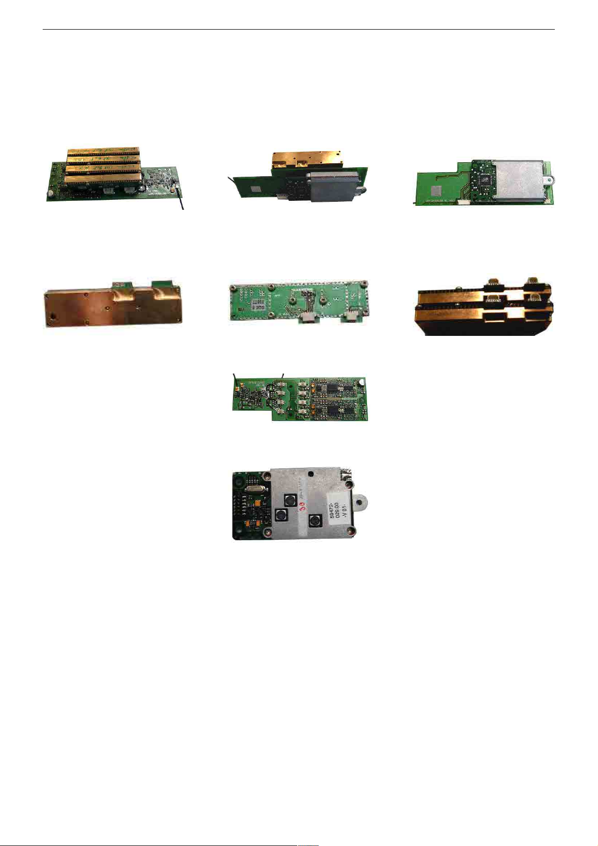
Abbildung 1a-c Tx4-Modul
Das Tx4-Funkmodul besteht aus den Teilen:
4x PLL Sende-Modul
WLM Module Tx4 (Data Transceiver)
The Tx4 module enables the simultaneous transmission of four audio
channels in the 864MHz frequency range. It is possible to select 10
transmission channels. 4 channels are used for the transmission of 2
stereo signals. For the transmission of control and data signals, a
modified version of the known (RCD2000) wireless data module
WLM869 is used. The modular system enables, for example, one Tx4
module with only two PLL modules as stereo Tx2(4).
Figure 1a-c Tx4 module
The wireless Tx4 module consists of:
4x PLL transmitter module
1x NF-Teil & HF-Endstufe (WLM-Trägerplatte)
1x WLM869 – Modul "Datenfunk-Modul"
Die vier PLL-Module werden auf die WLM-Trägerplatte (Bestückungsseite) aufgesteckt. Das WLM869-Modul wird auf die Rückseite gesteckt. Alle Versorgungs-, Steuer- und NF-Signale werden der WLMTrägerplatte über Platinensteckverbinder zugeführt. Der Antennenanschluss des WLM869 wird über ein kurzes Kabel mit dem WLM869Antenneneingang (UMP-Steckverbindung) verbunden. Die Antenne
wird an den HF-Verstärkerausgang angeschlossen (UMP-Steckverbindung).
1x AF unit & RF output stage (WLM chassis board)
1x WLM869 module "wireless data transmission module"
The four PLL modules are plugged into the WLM chassis board
(component side). The WLM869 module is plugged into the rear side.
All supply, control and AF signals are fed into the WLM chassis board
via plug-in board connectors. The antenna output of the WLM869 is
connected via a short cable with the WLM869 antenna input (UMP
connector). The antenna is connected to the RF amplifier output (UMP
connector).
1. WLM-Trägerplatte
Auf der Platte befinden sich zwei Stereo-Kompandersysteme, 2 Stereo-NF-TP-Filter (20kHz) und der 864MHz-HF-Endverstärker. Die NFVerarbeitung wird mit 9V/<100mA versorgt. Der HF-Verstärker wird
mit +5V/300mA versorgt, er kann über eine separate Steuerleitung
geschaltet werden. Der den PLL-Modulen zugeführte NF-Pegel, von
dem der FM-Frequenzhub (40kHz;75kHz) abhängt, kann für jeden
Kanal getrennt mit je einem Trimmpoti eingestellt werden. Die HFAusgänge der 4 PLL-Module werden zusammengeführt und durch die
HF-Endstufe verstärkt. Die verstärkten vier 864MHz-Audiofunk-Signale liegen zusammen mit dem 869MHz-Datenfunk-Signal an der
Tx4-UMP-Antennenbuchse.
1. WLM Chassis Board
This board carries two stereo compander systems, 2 stereo AF TP
filters (20kHz), and the 864MHz RF output amplifier. The AF processor
circuit is supplied with 9V/<100mA. The RF amplifier is supplied with
+5V/300mA; it can be switched via a separate control line. The AF level
passed on to the PLL modules determining the FM frequency deviation
(40kHz;75kHz) can be adjusted separately for every channel with a
potentiometer. The RF outputs of the 4 PLL modules are combined and
then amplified by the RF output stage. The amplified four 864MHz
audio radio signals lie along with the 869MHz data radio signal at the
Tx4-UMP antenna socket.
1 - 11

GRUNDIG Service Fine Arts Audion
2. PLL Sende-Modul
Dieses Modul beinhaltet VCO, PLL und drei Treiberstufen. Die Steuer- und NF-Signale werden dem Modul von der WLM-Trägerplatte über
Platinensteckverbinder zugeführt. Die HF-Verbindung zur Senderendstufe erfolgt ebenfalls über einen Platinensteckverbinder. Das Modul
liegt an der ungeschalteten +5V Versorgungsspannung. Die Stromaufnahme beträgt <40mA. Die Treiberstufen lassen sich über die
Steuerausgänge des PLL-Bausteins schalten. Nach Einschalten und
Konfiguration der PLL dürfen die Treiberstufen erst aktiviert werden,
wenn VCO&PLL sich auf die gewählte Frequenz eingestellt haben.
Diese "Einschwingzeit" beträgt ca. 500ms. Durch das verzögerte
Durchschalten der HF zur Endstufe wird verhindert, dass der gesamte benutzte Frequenzbereich und benachbarte Bereiche, beim einstellen des VCO durch die PLL, "überfahren" werden. Störungen werden somit vermieden. Nicht benötigte HF-Träger können über den PLLBaustein abgeschaltet werden (z.B. bei Betrieb nur eines Stereokanals). Die Stromaufnahme geht dadurch pro deaktiviertem
PLL(Sende-)-Modul um etwa 15mA zurück.
3. WLM869-Modul
Es wird eine Abwandlung des aus der RCD 2000 bekannten Datenfunkmodul (WLM869) zur Übertragung von Steuerdaten benutzt. Dieses wird auf die Rückseite der WLM-Trägerplatte aufgesteckt. Alle
Signale werden vom Trägerplattenstecker direkt zum WLM869-Modul
geleitet.
Der WLM869 Antennenausgang ist über ein Kabel mit UMP-Steckern
mit dem WLM869-Combinereingang auf der WLM-Trägerplatte verbunden.
4. Antennenanschlussplatte
Die vereinigten HF-Signale (Datenfunk & Audiofunk) werden von der
auf der WLM-Trägerplatte befindlichen Antennenbuchse über ein UMPAntennenkabel zur Antennenanschlussplatte geführt. Auf dieser erfolgt die Antennenanpassung. Die Antenne ist mit der Antennenanschlussplatte verbunden und besitzt einen ähnlichen Aufbau wie die
der LSP3-Lautsprecherbox.
2. PLL Transmitter Module
This module comprises the VCO, the PLL, and three driver stages.
The control and AF signals are injected via board connectors from the
WLM chassis board into the module. The RF connection to the
transmitter output stage is also effected via a board connector. The
module lies at the fixed +5V supply voltage. The current consumption
is <40mA. The driver stages can be switched via the control outputs of
the PLL module. After power-on and configuration of the PLL, the
driver stages must be activated only after the VCO&PLL has
synchronized with the selected frequency. This "transient time" is about
500ms. The delayed switching-through of the RF to the output stage
prevents the overmodulation of the entire used frequency range and
adjacent frequency ranges when the VCO is set by the PLL. Disturbances are prevented in this way. Not used RF carriers can be switched
off via the PLL module (for example if only one stereo channel is used).
Per deactivated PLL transmission module the current consumption is
reduced by about 15mA.
3. WLM869 Module
A modified version of the known (RCD 2000) wireless data module
(WLM869) is used for the transmission of the control data. This is
plugged into the rear side of the WLM chassis board. All signals are
directly passed from the chassis board connector on to the WLM869
module.
The WLM869 antenna output is connected via a cable fitted with UMP
plugs with the WLM869 combiner input on the WLM chassis board.
4. Antenna Connection Board
The combined RF signals (data & audio radio signals) are passed from
the antenna socket on the WLM chassis board via a UMP antenna
cable on to the antenna connection board. On this board the antenna
matching takes place. The antenna is connected with the antenna
connection board. It is constructed like the LSP3 loudspeaker box.
5. Steckverbindungen
5.1 Pinbelegung Steckverbindung WLM-Trägerplatte -> Audion-Hauptplatte:
ST101
Pin Signal Kommentar
1 Audio_A1 Links NF-Eingang Tx1
2 GND NF-Masse
(425mV
@1kHz = 40kHz Hub)
eff
3 GND NF-Masse
4 Audio_A2 Links NF-Eingang Tx3
5 Audio_B1
Rechts NF-Eingang Tx2 (425mV
6 GND NF-Masse
(425mV
@1kHz = 40kHz Hub)
eff
@1kHz = 40kHz Hub)
eff
7 GND NF-Masse
8 Audio_B2
Rechts NF-Eingang Tx4 (425mV
@1kHz = 40kHz Hub)
eff
ST102
Pin Signal Kommentar
1 E2 Enable PLL-Tx2; aktiv High (TTL-Pegel)
2 9V geschaltete Betriebsspannung NF-Teil (+9V/60mA)
3 E1 Enable PLL-Tx1; aktiv High (TTL-Pegel)
4 E4 Enable PLL-Tx4; aktiv High (TTL-Pegel)
5 GND NF-Masse
6 D Tx1-4PLL Data (+3V-Pegel)
7 WakeUp WLM WakeUp (+3V-Pegel)
8 C Tx1-4PLL Clock (TTL-Pegel)
9 TxD WLM TxD (+3V-Pegel)
10 E3 Enable PLL-Tx3; aktiv High (TTL-Pegel)
11 ON WLM Aktivierung; aktiv High (+3V-Pegel)
12 RTS WLM RTS (+3V Pegel)
13 OnPwr Tx1-4 Enable; aktiv High (TTL-Pegel)
14 CTS WLM CTS (+3V-Pegel)
15 5V feste Betriebsspannung WLM/Tx4 (+5V/500mA)
16 RxD WLM RxD (+3V-Pegel)
17 GND HF-Masse
18 GND HF-Masse
5. Plug-in Connectors
5.1 Pinning of the plug-in connectors WLM chassis board -> Audio
main board:
ST101
Pin Signal Comment
1 Audio_A1 Left AF input Tx1
2 GND AF ground
(425mV
@1kHz = 40kHz deviation)
rms
3 GND AF ground
4 Audio_A2 Left AF input Tx3
5 Audio_B1 Right AF input
6 GND AF ground
(425mV
Tx2 (425mV
@1kHz = 40kHz deviation)
rms
@1kHz = 40kHz deviation)
rms
7 GND AF ground
8 Audio_B2 Right AF input
Tx4 (425mV
@1kHz = 40kHz deviation)
rms
ST102
Pin Signal Comment
1 E2 Enable PLL-Tx2; active High (TTL level)
2 9V switched supply voltage, AF unit (+9V/60mA)
3 E1 Enable PLL-Tx1; active High (TTL level)
4 E4 Enable PLL-Tx4; active High (TTL level)
5 GND AF ground
6 D Tx1-4PLL Data (+3V level)
7 WakeUp WLM WakeUp (+3V level)
8 C Tx1-4PLL Clock (TTL level)
9 TxD WLM TxD (+3V level)
10 E3 Enable PLL-Tx3; active High (TTL level)
11 ON WLM activation; active High (+3V level)
12 RTS WLM RTS (+3V level)
13 OnPwr Tx1-4 Enable; active High (TTL level)
14 CTS WLM CTS (+3V level)
15 5V fixed supply voltage WLM/Tx4 (+5V/500mA)
16 RxD WLM RxD (+3V level)
17 GND RF ground
18 GND RF ground
Buchsen:
VCBAnt1: 869/864MHz HF gemeinsamer Antennenausgang
WLM869MHz & ATM(TX4); 864MHz (50Ω /+6dBm)
Sockets:
VCBAnt1: 869/864MHz RF common antenna output
WLM869MHz & ATM(TX4); 864MHz (50Ω /+6dBm)
1 - 12

GRUNDIG Service Fine Arts Audion
VCBAnt2: WLM869MHz-HF Antenneneingang
5.2 Pinbelegung Steckverbindung PLL (Sende-) -Modul -> WLMTrägerplatte
ST1
Pin Signal Kommentar
1 5V feste Betriebsspannung Tx (+5V/30mA)
2 GND Masse
3 Ex Enable PLL-Tx; aktiv High (TTL-Pegel)
4 Audio_Ax NF-Eingang Tx (10mV
5 D Tx PLL Data (TTL-Pegel)
@1kHz = 40kHz Hub)
eff
6 GND Masse
7 C Tx PLL Clock (TTL-Pegel)
8 GND Masse
ST2
Pin Signal Kommentar
1 GND HF-Masse
2 GND HF-Masse
3 864MHz HF HF-Ausgang (864MHz / 50Ω / 0dBm)
4 GND HF-Masse
5 GND HF-Masse
6 GND HF-Masse
VCBAnt2: WLM869MHz RF antenna input
5.2 Pinning of plug-in connector PLL (transmitter) module -> WLM
chassis board
ST1
Pin Signal Comment
1 5V fixed supply voltage Tx (+5V/30mA)
2 GND Ground
3 Ex Enable PLL-Tx; active High (TTL level)
4 Audio_Ax AF input Tx (10mV
5 D Tx PLL Data (TTL level)
@1kHz = 40kHz deviation)
rms
6 GND Ground
7 C Tx PLL Clock (TTL level)
8 GND Ground
ST2
Pin Signal Comment
1 GND RF ground
2 GND RF ground
3 864MHz RF RF output (864MHz / 50Ω / 0dBm)
4 GND RF ground
5 GND RF ground
6 GND RF ground
1 - 13

GRUNDIG Service Fine Arts Audion
Servicefunktionen
Servicefunktionen RCD 8300
Die Servicefunktionen der RCD 8300 umfassen:
- Anzeigefunktionen,
- Testfunktionen,
- Einstellen von Factorydaten,
- Reset von Einstellungen,
- Vorbereitung zum Softwareupdate,
- Notinstallation einer Fernbedienung.
1. Servicemenü
1.1 Zugang zu den Servicefunktionen
- Beim Einschalten mit dem Netzschalter Taste PLAY/STOP gedrückt halten, bis das Servicemenü erscheint.
- Wenn das Gerät geöffnet ist, kann im Betrieb jederzeit die TestTaste auf der Steuerplatine gedrückt werden, um das Servicemenü
aufzurufen.
Hinweis:
Eine Funktion zum Reset des RCD8300 (Steuergeräts) wird dem
Kunden angeboten. Diese wird aktiviert, indem beim Einschalten mit
dem Netzschalter die Taste SOURCE gedrückt gehalten wird. Dadurch
wird das EEPROM (außer Sprachen und Factorydaten) gelöscht.
Nach Aus/Einschalten erfolgt eine Neuinstallation.
1.2 Navigation im Servicemenü
Das Servicemenü bietet eine Liste von Servicefunktionen. Eine Funktion dieser Liste kann mit den Tasten PLUS / MINUS selektiert werden.
Service Functions
Service Functions RCD 8300
The service functions of the RCD 8300 comprise:
- display functions,
- test functions,
- changing the factory parameters,
- resetting factory parameters to defaults,
- preparation of software updates,
- emergency installation of a remote control.
1. Service Menu
1.1 Access to the Service Functions
- When switching on with the mains switch, press and hold down the
PLAY/STOP button until the Service Menu is displayed.
- When the unit is opened up, it is possible to press at any time the test
button on the control (master) board to call up the Service Menu.
Note:
A function for resetting the RCD8300 (control unit) is proposed the
customer. This function is activated by pressing and holding down the
SOURCE button while switching on with the mains switch. This clears
the EEPROM (except the languages and the factory parameters). After
switching off/on, a new installation is started.
1.2 Navigation in the Service Menu
The Service Menu provides a list of service functions. The functions in
this list can be selected with the PLUS / MINUS buttons.
Menüebene Auswahlliste
Taste Bedeutung
SOURCE Aktiviert die angezeigte Servicefunktion
PLUS, MINUS Scrollen durch die Liste der Servicefunktionen
PLAY/STOP STANDBY Verlassen des Servicemenüs
Menüebene Servicefunktion aktiviert
Taste Bedeutung
SOURCE Funktionsspezifisch (Anwahl, Bestätigung)
PLUS, MINUS Funktionsspezifisch (Auswahl, Ein/Aus, Vor/Zurück)
PLAY/STOP Funktionsspezifisch
STANDBY 'Zurück' zur Auswahlliste
1.3 Beenden des Servicemenüs
- Die Taste STANDBY auf der obersten Menüebene (Auswahlliste)
verläßt das Servicemenü und wechselt in den Normalbetrieb.
- Mit der Test-Taste auf der Steuerplatine kann das Servicemenü
verlassen werden.
- Nach einigen Funktionen muß das Gerät mit dem Netzschalter aus/
eingeschaltet werden (z.B. nach 'flashen')
2 Auswahlliste (Menübaum)
Beim Eintritt in den Servicebetrieb wird der erste Eintrag der Auswahlliste dargestellt.
PLUS, bzw. MINUS ändert die Auswahl.
SOURCE aktiviert die dargestellte Funktion.
Hinweis:
SO FORMATIERTE FUNKTIONEN"
"
wirken auf Factorydaten.
Menu level - select list
Button Meaning
SOURCE Activates the indicated service function
PLUS, MINUS Scrolls through the service function list
PLAY/STOP STANDBY Exits the Service Menu
Menu level - service function activated
Button Meaning
SOURCE Function-specific (selection, confirmation)
PLUS, MINUS Function-specific (selection, on/off, forward/back)
PLAY/STOP Function-specific
STANDBY Back to select list (menu)
1.3 Exiting the Service Menu
- Pressing the STANDBY button in the top menu level (select list) exits
the Service Menu and switches in normal operating mode.
- Pressing the Test button on the control board exits the Service
Menu.
- After certain functions the unit must be switched off/on with the
mains switch (e.g. after 'flashing')
2 Select List (Menu Tree)
When entering the service mode, the first entry in the menu is
displayed.
PLUS or MINUS changes the selection.
SOURCE activates the displayed function.
Note:
"
FUNCTIONS OF THIS FORMAT"
affect the factory parameters.
Auswahlliste in der Darstellungsreihenfolge:
FLASH RCD 8300
CLEAR SIGNAL EEPROM
CLEAR MASTER EEPROM
SHOW VERSIONS
CHECK COMPONENTS
DETECT HARDKEYS
AUDIO TRANSMITTER TEST
DISPLAY TEST
SCREEN SETTINGS
DETECT ROOM BRIGHTNESS
TRAY FORCE
Items order in the select list:
FLASH RCD 8300
CLEAR SIGNAL EEPROM
CLEAR MASTER EEPROM
SHOW VERSIONS
CHECK COMPONENTS
DETECT HARDKEYS
AUDIO TRANSMITTER TEST
DISPLAY TEST
SCREEN SETTINGS
DETECT ROOM BRIGHTNESS
TRAY FORCE
2 - 1
GRUNDIG Service Fine Arts Audion
TRAY FORCE REDUCED
TRAY MAX CURRENT
DISPLAY ROTATION MAX CURRENT
STORE SERVO PARAMETERS TO EEPROM
RESET FACTORY PARAMETER TO DEFAULTS
TOGGLE SCREEN MENUES
INSTALL PR1
DAB SIGNAL QUALITY
3. Beschreibung der Funktionen
3.1 Softwareupdate des Steuergeräts
Bildschirm:
TRAY FORCE REDUCED
TRAY MAX CURRENT
DISPLAY ROTATION MAX CURRENT
STORE SERVO PARAMETERS TO EEPROM
RESET FACTORY PARAMETER TO DEFAULTS
TOGGLE SCREEN MENUES
INSTALL PR1
DAB SIGNAL QUALITY
3. Description of the Functions
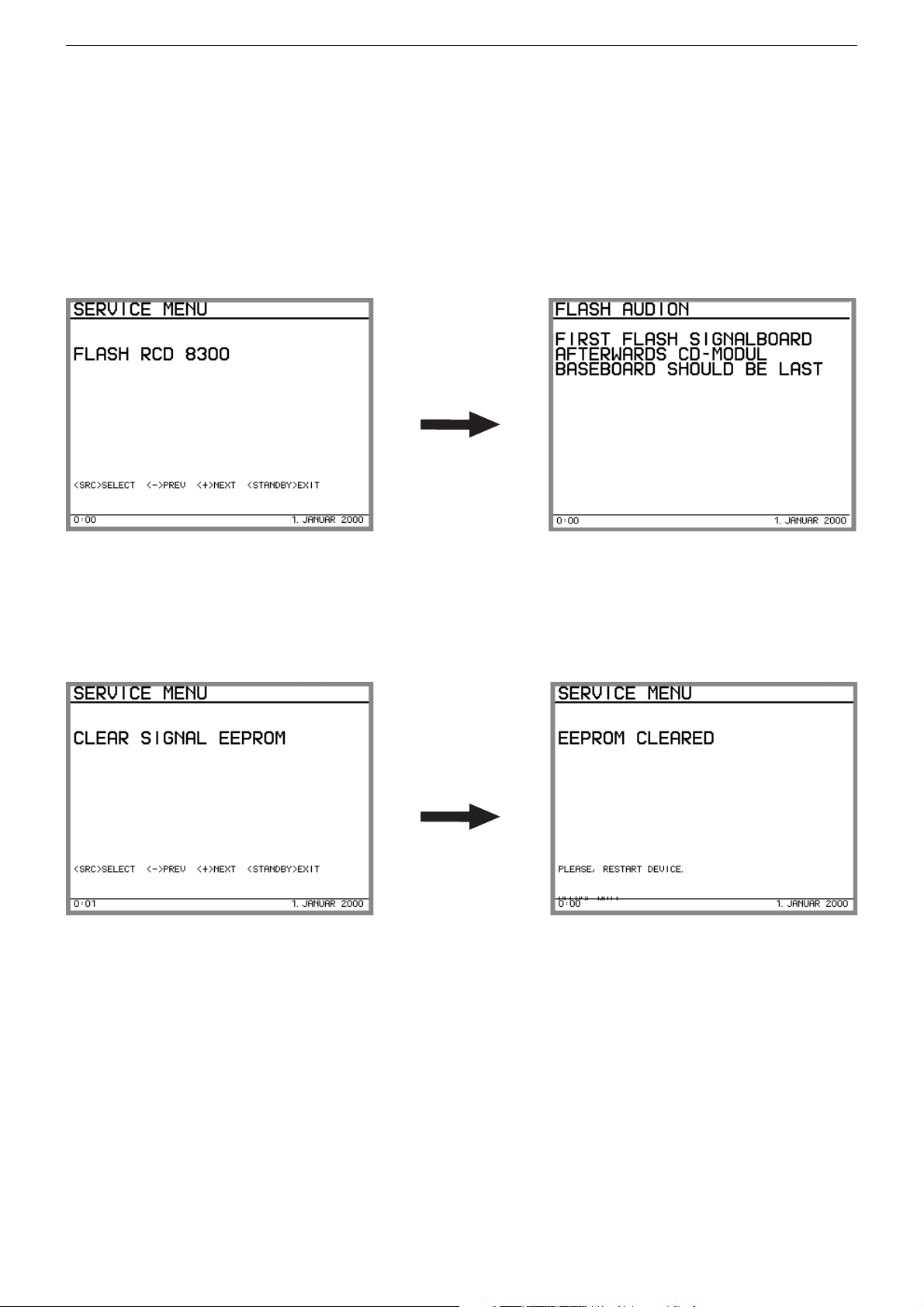
3.1 Flash RCD 8300 (software update of the control unit)
Display on picture screen:
Bedeutung:
Anlage in Betriebszustand versetzen zum Flashen: CD-Fach wird
geöffnet, CD-Modul und Tuner sind eingeschaltet.
Bedienung:
keine, Netz Aus/Ein nach dem Flashen nötig.
3.2 Signal EEPROM löschen
Bildschirm:
Bedeutung:
Löschen von Einstellungen im Tuner EEPROM, z.B. Senderlisten,
LastStation …
Bedienung:
keine
Meaning:
Setting the unit into the operating mode for flashing: CD tray is opend,
CD module and tuner switched on.
Operation:
none, power off/on after flashing required.
3.2 Clear Signal EEPROM
Display on picture screen:
Meaning:
Clear settings in the tuner EEPROM, e.g. channel lists, last station
memory ...
Operation:
none
2 - 2
GRUNDIG Service Fine Arts Audion
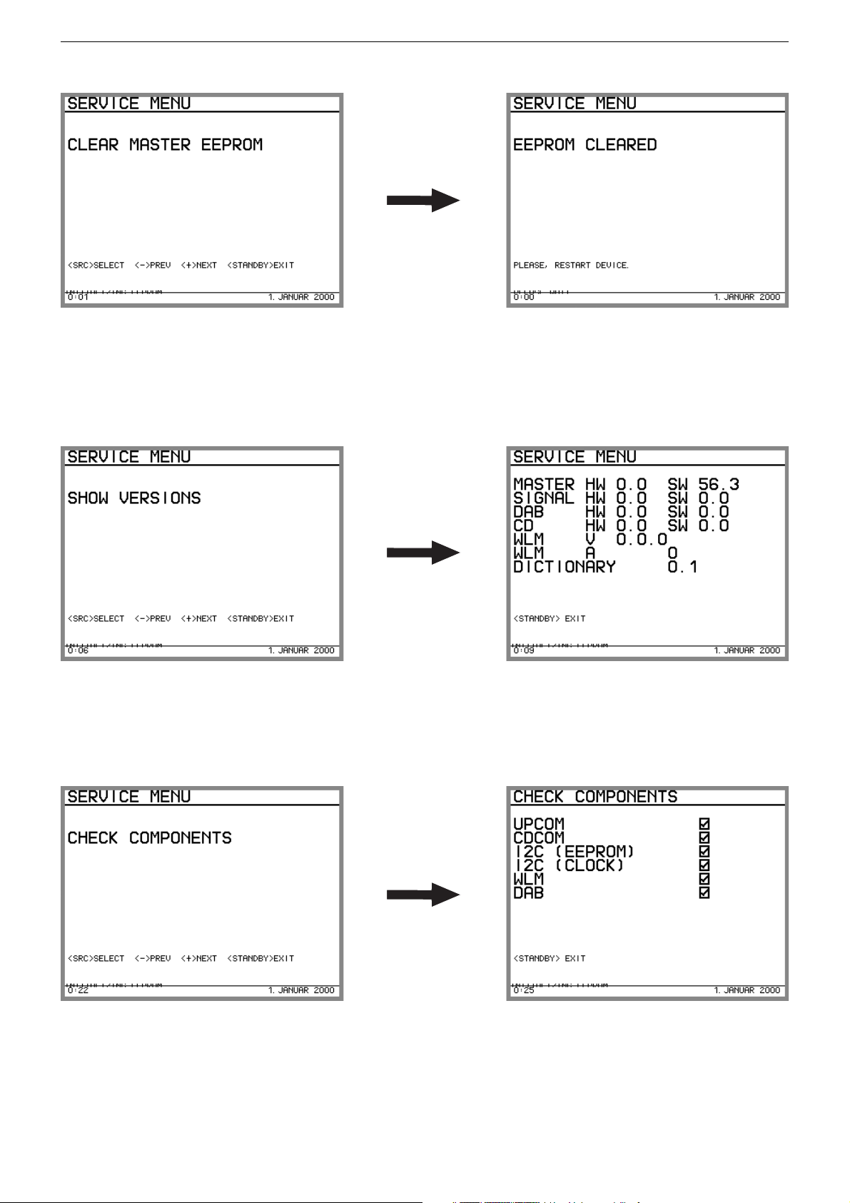
3.3 Steuerplatine Master-EEPROM löschen
Bildschirm:
Bedeutung:
Löschen von Einstellungen im EEPROM der Steuerplatine, z.B. Sprache, Aufstellposition, Systemkonfiguration, ...
Bedienung:
keine, Netz Aus/Ein nötig
3.4 Hardware und Softwareversionen anzeigen
Bildschirm:
3.3 Control Board Clear Master EEPROM
Display on picture screen:
Meaning:
Clears EEPROM settings on the master board, e.g. language, unit
position, system configuration, ...
Operation:
none, power on/off (restart) required
3.4 Show Versions (hardware and software)
Display on picture screen:
Bedeutung:
Versionsanzeige von eingebauter Hard- und Software
Bedienung:
keine
3.5 Hardwaretest
Bildschirm:
Bedeutung:
Test von Hardwarebaugruppen
Bedienung:
keine
Meaning:
Indication of the versions of the built-in hardware and software.
Operation:
none
3.5 Check Components
Display on picture screen:
Meaning:
Test of hardware components.
Operation:
none
2 - 3
GRUNDIG Service Fine Arts Audion
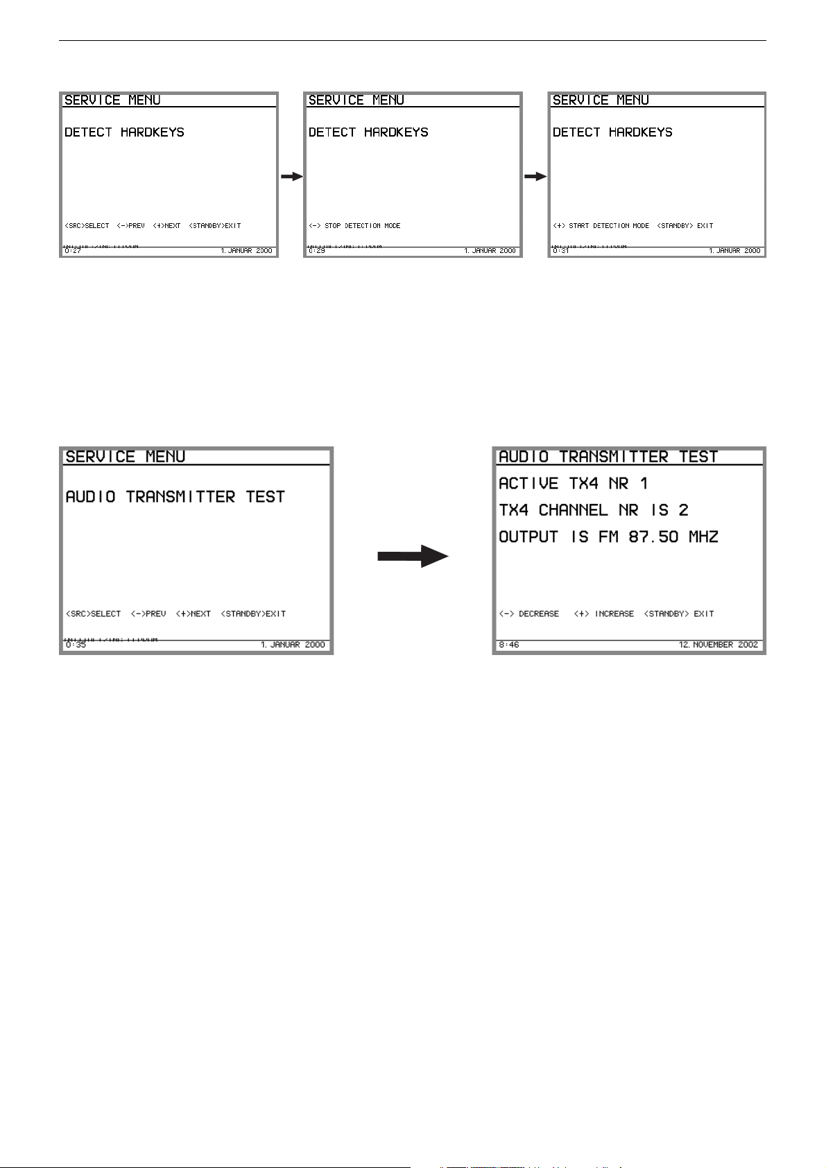
3.6 Tastenerkennung
Bildschirm:
Bedeutung:
Anzeige von ID und Spannungswert einer Taste (SOURCE, PLUS,
MINUS, PLAY_STOP, STANDBY, OPENCLOSE)
Achtung: Die Tastenerkennung muß erst wieder ausgeschaltet werden, um das Menü mit STANDBY verlassen zu können (dadurch kann
auch die Standbytaste geprüft werden).
Bedienung:
PLUS schaltet Tastenerkennung ein.
MINUS schaltet Tastenerkennung aus
3.7 Audio Transmitter Test
Bildschirm:
3.6 Detect Hardkeys
Display on picture screen:
Meaning:
Indication of the ID and the voltage rating of a button (SOURCE, PLUS,
MINUS, PLAY_STOP, STANDBY, OPENCLOSE)
Attention: it is neccessary first to switch off the button identification to
exit the menu with button STANDBY (in this way the standby button
can also be checked).
Operation:
PLUS switches on the button ID.
MINUS switches off the button ID.
3.7 Audio Transmitter Test
Display on picture screen:
Bedeutung:
Test der 4 Audiosender. Jeweils nur ein Sender aktiv, der Sendekanal
ist fest eingestellt, jedoch für jeden Sender unterschiedlich (gleiche
Kanäle wie bei WT2-Servicebetrieb), Signal (Rauschen) vom FMTuner bei 87.5 MHz.
Bedienung:
PLUS, MINUS Es wird jeweils der nächste/vorherige Sender einge-
schaltet
Meaning:
Test of the 4 audio transmitters. Only one transmitter active for every
test. The transmitter channel is fixed, but different for every transmitter
(same channels as for the WT2 service mode). Signal (noise) from FM
tuner at 87.5 MHz.
Operation:
PLUS, MINUS The next/previous transmitter is switched on.
2 - 4
GRUNDIG Service Fine Arts Audion
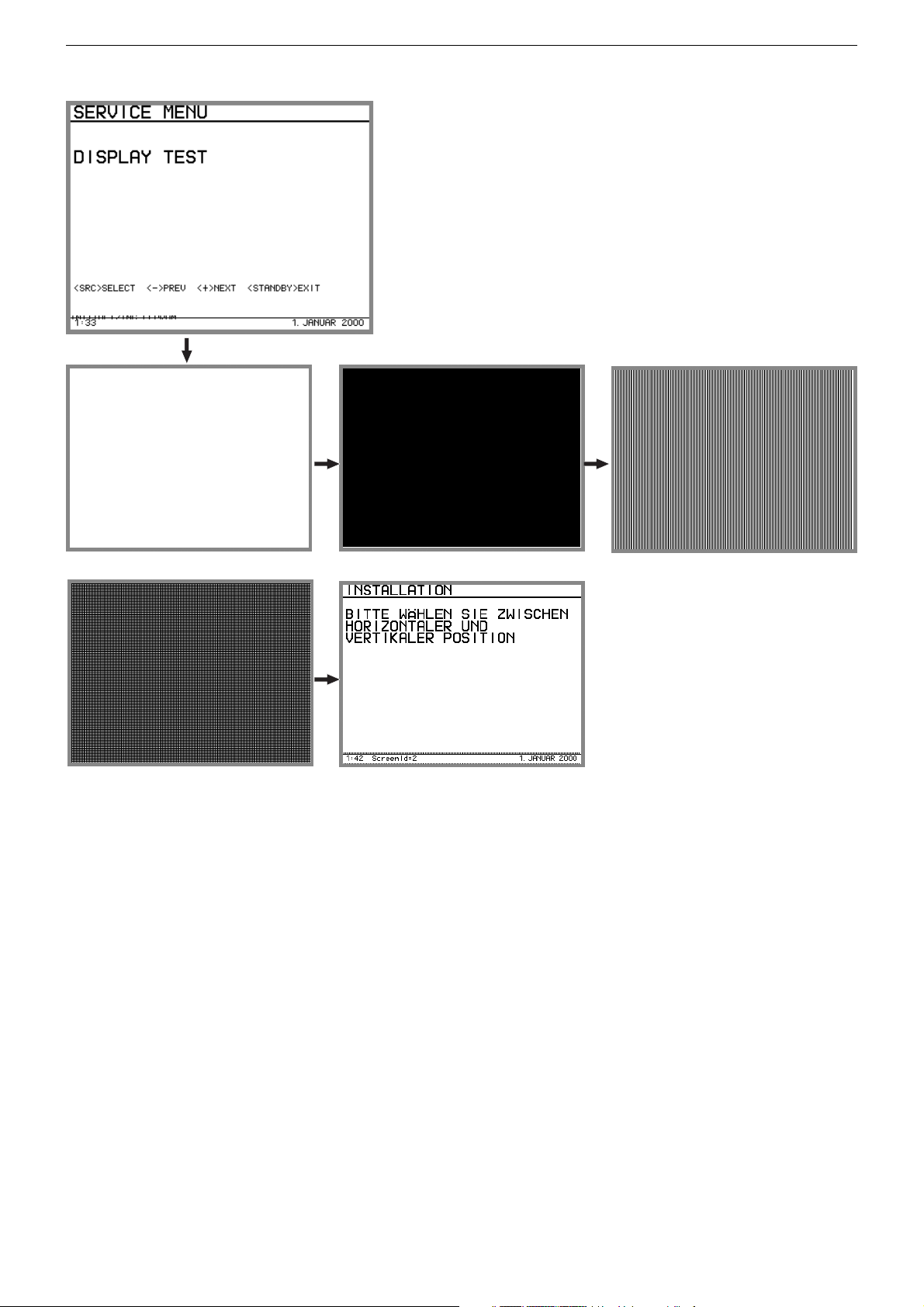
3.8 Display Test
Bildschirm:
3.8 Display Test
Display on picture screen:
Bedeutung:
Optische Beurteilung des Displays auf Hardwarefehler.
1. Alle Pixel hell
2. Alle Pixel dunkel
3. Senkrechte Linien
4. Waagrechte Linien (Anzeige funktioniert nicht so recht)
5. Autoplay Screens
Alle vorhandenen Screens werden der Reihe nach angezeigt. In der
unteren Zeile wird die zugehörige Screennummer ausgegeben, die
in der Software verwendet wird.
Bedienung:
PLUS, MINUS schaltet durch die Liste der Displaytests
Meaning:
Visual check of the display for hardware failures:
1. All Pixels bright.
2. All Pixels dark.
3. Vertical lines.
4. Horizontal lines (poor display function).
5. Autoplay screens:
All screens are displayed one after the other. In the bottom line the
associated screen number used in the software is shown.
Operation:
PLUS, MINUS scrolls through the display test list.
2 - 5
GRUNDIG Service Fine Arts Audion
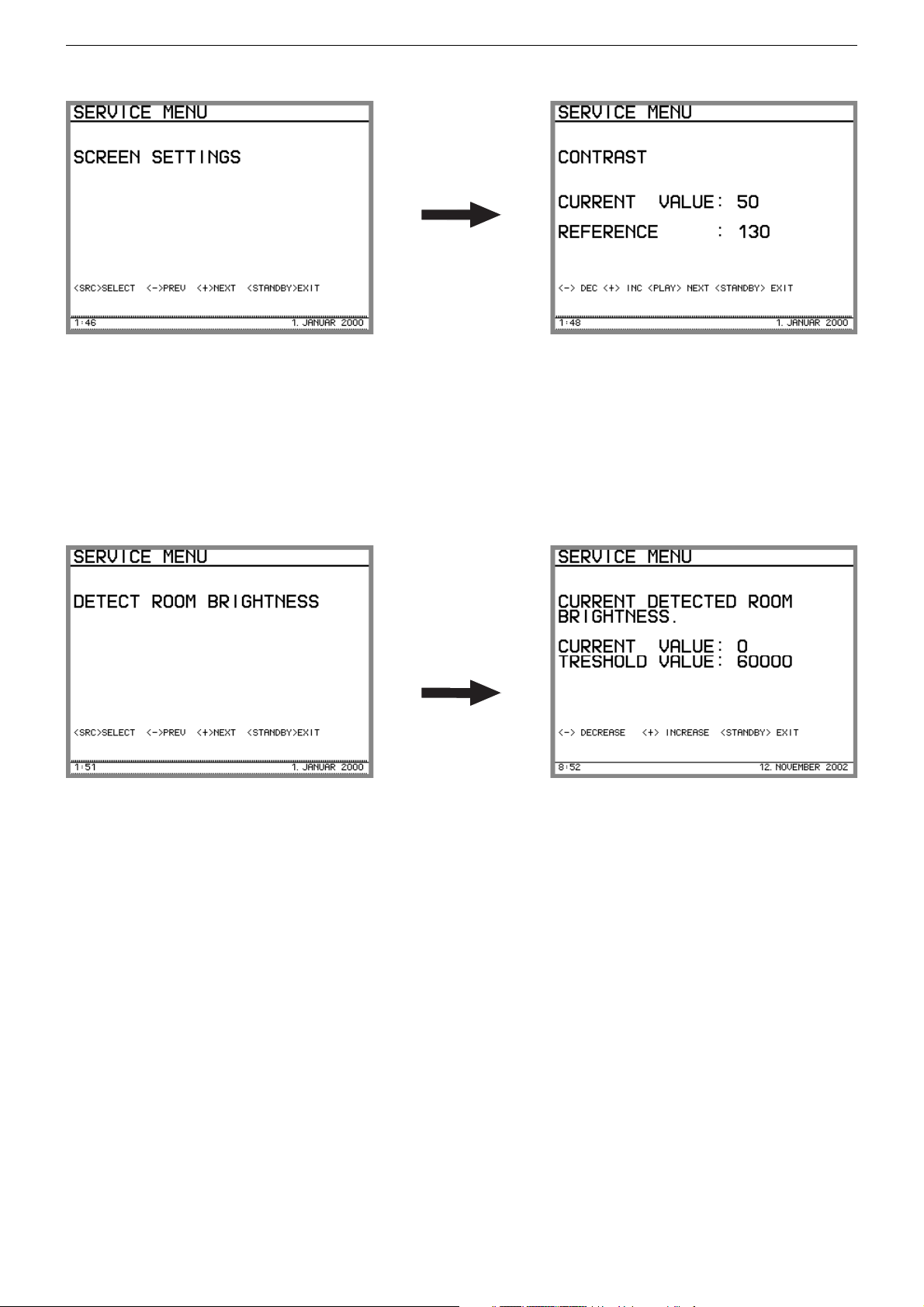
3.1 Bildschirm einstellen (Kontrast)
Bildschirm:
Bedeutung:
Einstellen des Kontrastwertes (Current Value), Wertebereich 0..100
Einstellen des Kontrast-Referenzpunktes, Wertebereich 50..150.
Der Referenzpunkt sollte so eingestellt werden, daß bei Current Value
= 0 und 100 die Anzeige noch lesbar ist. Beim Eintritt in diesen Screen
ist der oberste Wert selektiert.
Bedienung:
PLUS, MINUS ändert den Kontrastwert oder Referenzpunkt um +/-5
PLAY/STOP wechselt zwischen Kontrastwert und Referenzpunkt
3.2 Schwellwert Tag/Nacht einstellen
Bildschirm:
3.1 Screen Settings (Contrast)
Display on picture screen:
Meaning:
Contrast setting (Current Value), setting range 0...100
Setting of the contrast reference point, setting range 50...150.
The reference point should be set so that the display still can be read
off at a current value of 0 and 100. When entering this screen the top
value is selected.
Operation:
PLUS, MINUS changes the contrast or reference point setting by +/-5
PLAY/STOP switches between contrast and reference point setting.
3.2 Detect Room Brightness
Display on picture screen:
Bedeutung:
Einstellung der Schwelle zur Unterscheidung Tag/Nacht. Es wird der
aktuell gemessene LDR-Wert angezeigt. Die Schwelle (Treshold) wird
ebenfalls angezeigt und kann in 1000er Schritten zwischen 0 und
65535 geändert werden (Defaultwert 60000). Für die RCD8300 ist
Nacht, wenn der gemessene Wert oberhalb der Schwelle liegt.
Bedienung:
PLUS, MINUS Die Schwelle wird in 1000er Schritten geändert.
Hinweis:
- Die Tag-/Nachtschwelle hat nur Auswirkung auf die Traybeleuchtung im Standby.
- Die Tag-/Nachtschwelle wird nur ca. alle 10s überprüft.
Meaning:
Setting of the day/night brightness threshold. The actually detected
room brightness and the threshold are indicated. The threshold can be
changed in steps of 1000 between 0 and 65535 (default setting 60000).
The RCD8300 assumes night if the measured value lies above the
threshold.
Operation:
PLUS, MINUS The threshold is changed in steps of 1000.
Note:
- The day/night threshold affects only the tray illumination in standby
mode.
- The day/night threshold is measured only every 10s.
2 - 6
GRUNDIG Service Fine Arts Audion
3.3 Stromwerte einstellen
Im Gegensatz zu anderen Servicefunktionen werden die einzelnen
Stromwerte nicht sofort bei jeder Änderung gespeichert, sondern
werden erst alle eingestellt und dann mit der Funktion
EEPROM schreiben‘
abgespeichert.
‚Stromwerte ins
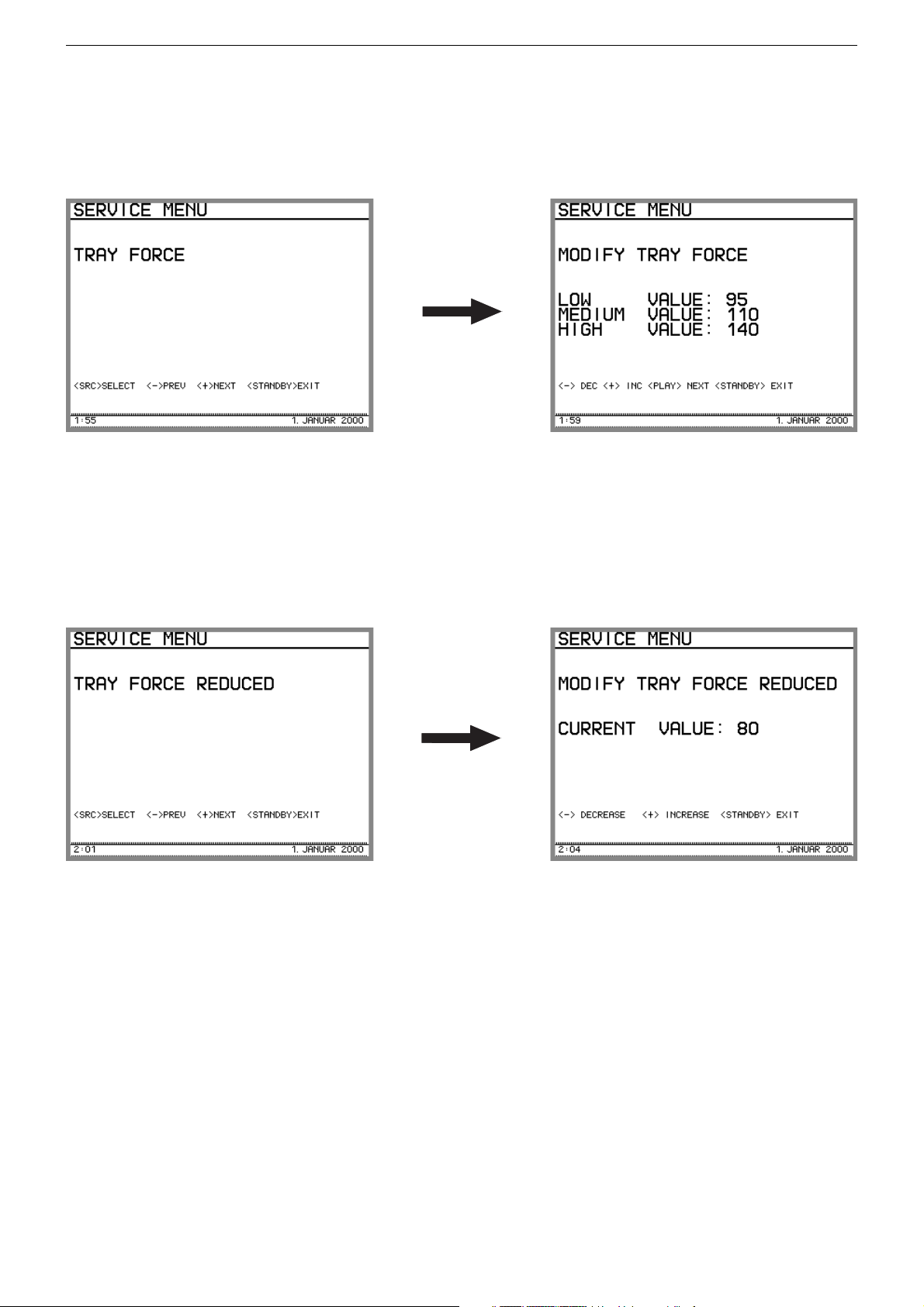
3.3.1 Stromwerte für CD Fach einstellen: TRAY FORCE
Bildschirm:
Bedeutung:
Einstellen der Kraft, mit der das CD-Fach geöffnet/geschlossen wird.
Es gibt folgende Grenzwerte: LOW, MEDIUM, HIGH. Beim Eintritt in
diesen Screen ist der oberste Wert selektiert.
Bedienung:
PLUS, MINUS ändert den Wert +/-5
PLAY/STOP wechselt zwischen LOW, MEDIUM, HIGH
3.3 Current Settings
In contrast to other service functions, the individual current settings are
not saved after every change but are saved together when the settings
are completed with the
‚Store servo parameters to EEPROM ‘
.
3.3.1 Tray Force
Display on picture screen:
Meaning:
Setting of the force with which the CD tray is opend/closed.
Limit values: LOW, MEDIUM, HIGH.
When entering this screen, the top value is selected.
Operation:
PLUS, MINUS change the setting in +/-5 steps.
PLAY/STOP switches between LOW, MEDIUM, HIGH.
3.3.2 Stromwerte für CD Fach einstellen: TRAY FORCE
REDUCED
Bildschirm:
Bedeutung:
Einstellen der Kraft, mit der das CD-Fach geschlossen wird, sobald der
Endschalter angesprochen hat.
Bedienung:
PLUS, MINUS ändert den Wert +/-5
3.3.2 Tray Force Reduced
Display on picture screen:
Meaning:
Setting of the force with which the CD tray is closed when the limit
switch responds.
Operation:
PLUS, MINUS change the setting in +/-5 steps.
2 - 7
GRUNDIG Service Fine Arts Audion
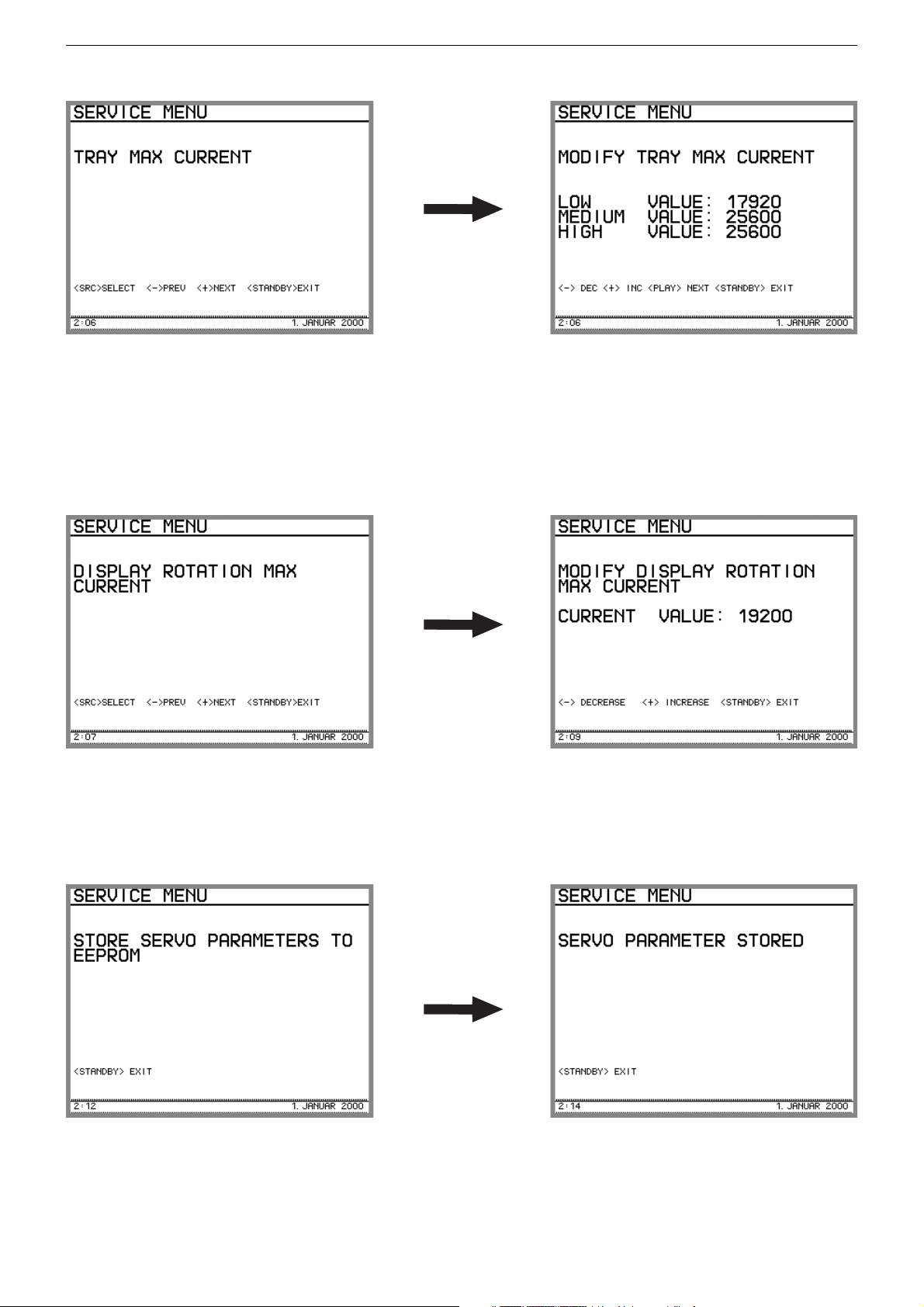
3.3.3 Stromwerte für CD Fach einstellen: TRAY MAX CURRENT
Bildschirm:
Bedeutung:
Einstellen des maximalen Stromes mit dem der CD-Fach-Motor betrieben wird Es gibt folgende Grenzwerte: LOW, MEDIUM, HIGH. Beim
Eintritt in diesen Screen ist der oberste Wert selektiert.
Bedienung:
PLUS, MINUS ändert den Wert +/- 5*255 Schritten
PLAY/STOP wechselt zwischen LOW, MEDIUM, HIGH
3.3.4 Stromwert für Displaydrehung einstellen
Bildschirm:
3.3.3 Tray Max. Current
Display on picture screen:
Meaning:
Setting of the maximum current with which the CD tray motor is
operated. The following limit values are available: LOW, MEDIUM,
HIGH. When entering this screen, the top value is selected.
Operation:
PLUS, MINUS changes the value in +/- 5*255 steps.
PLAY/STOP switches between LOW, MEDIUM, HIGH
3.3.4 Display Rotation Max. Current
Display on picture screen:
Bedeutung:
Einstellen des maximalen Stromes für den Displaymotor.
Bedienung:
PLUS, MINUS ändert den Wert +/- 255 Schritten
3.3.5 Stromwerte ins EEPROM schreiben
Bildschirm:
Bedeutung:
Speichert alle Stromwerte im Factorybereich im EEPROM ab.
Bedienung:
keine
Meaning:
Setting of the maximum display motor current.
Operation:
PLUS, MINUS changes the value in +/- 255 steps.
3.3.5 Store Servo Parameters to EEPROM
Display on picture screen:
Meaning:
Saves all servo parameters into the EEPROM.
Operation:
none
2 - 8
GRUNDIG Service Fine Arts Audion
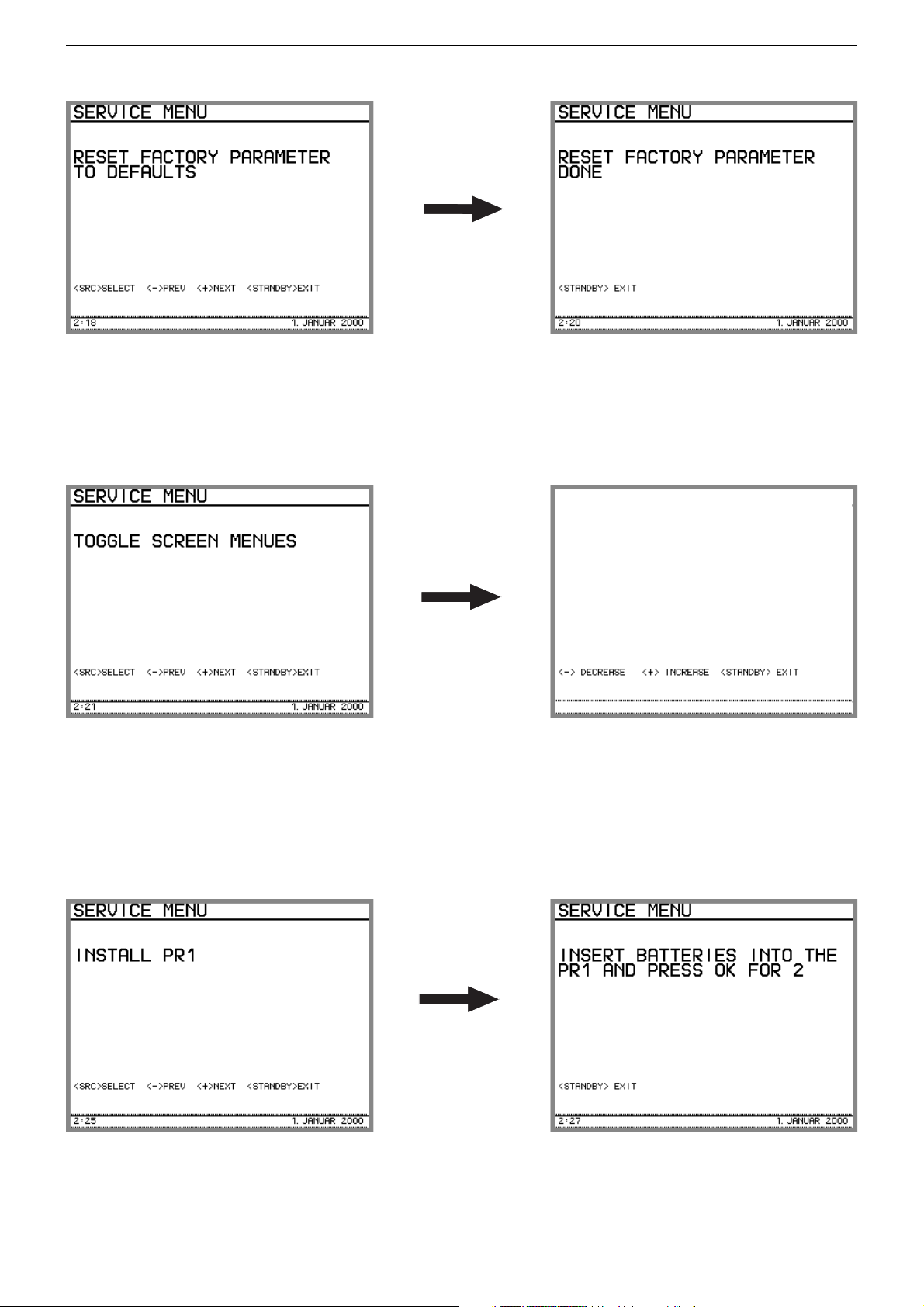
3.4 Reset Factorydaten
Bildschirm:
Bedeutung:
Es werden alle Factorydaten mit Defaultwerten überschrieben. Die
Abgleichdaten aus der Fertigung sind nicht mehr vorhanden.
Bedienung:
keine
3.5 Screens überprüfen
Bildschirm:
3.4 Reset Factory Parameters
Display on picture screen:
Meaning:
Resetting of all factory parameters to default. The factory settings is not
available any longer.
Operation:
none
3.5 Toggle Screen Menus
Display on picture screen:
Bedeutung:
Layout und Sprache prüfen Es werden alle Screens der Reihe nach
(wie in der Software implementiert) dargestellt. Der erste Screen ist ein
leerer Screen. Beim Eintritt in diese Funktion wird immer mit dem
ersten Screen begonnen.
Bedienung:
PLUS, MINUS nächsten Screen aufrufen
3.6 PR 1 Installation
Bildschirm:
Bedeutung:
Installation einer PR1 (damit kann ohne Neuinstallation und ohne
bereits installierte PR1 eine Fernbedienung installiert werden).
Bedienung:
keine
Meaning:
This function checks the layout and language of the screens. The
screens are displayed on after the other (as implemented in the
software). The first screen is empty. This function is always started with
the first screen.
Operation:
PLUS, MINUS calls up the next screen.
3.6 Install PR 1
Display on picture screen:
Meaning:
Installation of a PR1 (this permits the installation of a remote control
without new installation and without existing PR 1 installation).
Operation:
none
2 - 9
GRUNDIG Service Fine Arts Audion
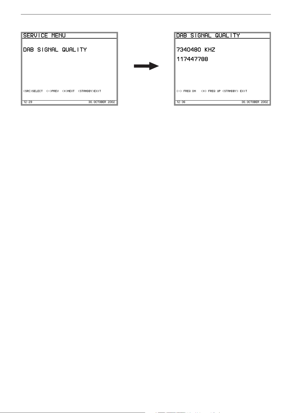
3.7 DAB Signal Qualität feststellen
Bildschirm:
Bedeutung:
Zeigt für die aktuelle Frequenz den ‚Error Frame Count‘-Wert (EFC),
der über 2.4 sec akkumuliert wird. Beim EFC handelt es sich um
Bitfehler, die man bemerkt, wenn man das re-encodierte DAB-Signal
mit dem empfangenen Signal vergleicht. Berücksichtigt wird nur der
Kanal mit den Steuerinformationen (FIC). Um eine Fehlerrate zu
erhalten, muß man den Wert durch 2,4 * 32000 teilen. Je kleiner der
Absolutwert, desto besser ist der Empfang. DAB-Empfang ist prinzipiell bei Werten zwischen 0 und ca. 4000 möglich. Akzeptabler DABEmpfang benötigt Werte unter 800. Ist kein DAB-Signal empfangbar,
wird der Wert auf 4294967295 gesetzt.
Intention:
Beurteilung des DAB-Empfangs; Optimale Ausrichtung der Antenne
(Muß für jede empfangbare Frequenz erfolgen).
Bemerkung:
Dieser Wert ist langzeitgefiltert
Bedienung:
PLUS, MINUS: Frequenz verändern: Schrittweite ist jeweils eine
CEPT-Frequenz (z.B. von Kanal 12 B auf Kanal 12 A)
3.7 DAB Signal Quality
Display on picture screen:
Meaning:
Display of the ‚Error Frame Count‘ value (EFC) accumulated over 2.4
sec for the current frequency. The EFC is a Bit error obtained when
comparing the re-encoded DAB signal with the received signal. Only
one channel with the control information (FIC) is taken into account. To
obtain an error rate, the value must be divided by 2.4 * 32000. The
lower the absolute value the better the reception quality. DAB reception is principally possibly with values between 0 and about 4000.
Acceptable DAB reception requires values below 800. If no DAB signal
can be received, the value is set to 4294967295.
Intention:
Evaluation of the DAB reception quality, optimum orientation of the
antenna (this must be done for each receivable frequency).
Note:
This value is long-time filtered.
Operation:
PLUS, MINUS: frequency change: the frequency step is always a
CEPT frequency (e.g from channel 12 B to channel
12 A).
Servicefunktionen LSP 2 / LSP 3
1. Servicebetrieb LSP
1.1 Kurzbeschreibung
Der Servicebetrieb der LSP umfasst zwei Hauptmodi "AudiopfadTest" und "Komponenten-Test".
1.1.1 Audiopfad-Test
Dieser Testmodus erlaubt das schnelle Überprüfen eines AudiofunkSystems. Dazu wird durch einen Sender (RCD8300 oder WT2) auf
vordefinierten Frequenzen ein NF-Signal übertragen. Ein LSP im
Audiopfad-Test kann nun diese Frequenzen "anfahren" und das NFSignal wiedergeben.
1.1.2 Komponenten-Test
Der Komponenten-Test ermöglicht das Testen einzelner LSP Baugruppen bzw. Funktionseinheiten auf korrekte Funktionsweise.
1.1.3 Weitere Servicefunktionen
Des weiteren stehen im Normalbetrieb weitere Serviceunterstützungen
zur Verfügung:
- Versionsabfrage
- Unterstützende Funktionen für Customer Channel Select (CCS)
1.2 Zugang zu den Servicefunktionen
1.2.1 Zugang zum Audiopfad-Test
Wird beim Einschalten des LSP mittels "NETZ EIN"-Schalter gleichzeitig die "RESET"-Taste gedrückt, wird der Audiopfad-Test aktiviert. Die
INSTALL-LED signalisiert den Eintritt in diesen Modus durch zyklisches einmaliges Aufleuchten in Grün.
1.2.2 Zugang zum Komponenten-Test
Wird beim Einschalten des LSP mittels "NETZ EIN"-Schalter gleichzeitig die "SYSTEM TEST"-Taste (SW1, Audio-Platte X46, Y6) gedrückt,
wird der Komponenten-Test aktiviert. Die SYSTEMTEST-LED signalisiert den Eintritt in diesen Modus durch zyklisches Aufleuchten in Grün.
1.2.3 Zugang zu weiteren Testfunktionen
Die weiteren Testfunktionen sind im normalen Betriebsmodus erreichbar.
Service Functions LSP 2 / LSP 3
1. LSP Service Mode
1.1 Brief Description
The LSP service mode comprises the main modes "Audio path test"
and "Component test".
1.1.1 Audio Path Test
This test mode enables the fast check of a wireless audio system. For
this, an AF signal is transmitted via a transmitter (RCD8300 or WT2)
on predefined frequencies. An LSP under the audio path test can only
tune to these frequencies and reproduce the AF signal.
1.1.2 Component Test
The component test enables testing of the correct function of individual
LSP modules or functional units.
1.1.3 Further Service Functions
Further service support functions are available for normal operating
mode:
- Version inquiry
- Support function for Customer Channel Select (CCS) mode.
1.2 Acces to the Individual Service Functions
1.2.1 Acces to the Audio Path Test
The audio path test is activated by pressing the "RESET" button while
switching the LSP on with the "POWER ON" switch. The INSTALL LED
signals the activation of this mode by one flashing cycle in green.
1.2.2 Access to the Component Test
The component test is activated by pressing the "SYSTEM TEST"
button (SW1, Audio Board X46, Y6) while switching the LSP on with
the "POWER ON" switch. The SYSTEM TEST LED signals the
activation of this mode by flashing cycle in green.
1.2.3 Access to Further Test Functions
The further test functions can be accessed in normal operating mode.
2 - 10

GRUNDIG Service Fine Arts Audion
1.3 Beenden des Servicebetriebs
LSP ausschalten.
2. Beschreibung der Funktionen
2.1 Audiopfad-Test
Im Audiopfad-Test stellt der LSP am Audiofunkemfänger in zirkulär
umlaufendem Wechsel einen der vier vordefinierten Kanäle ein und
gibt das empfangene NF-Signal mit Lautstärke 25 wieder. Der aktuell
eingestellte Programmschritt wird durch einen Blinkcode der INSTALLLED angezeigt. Der jeweils nächste Programmschritt wird durch
kurzes Drücken des RESET-Tasters aktiviert. Nach dem letzten
Programmschritt erfolgt ein Rücksprung zum ersten Programmschritt.
Die Programmschritte sind derzeit wie folgt definiert:
Programmschritt Kanaleinstellung INSTALL-LED Blinkcode
Test 1 Kanal 2 1 x kurz grün
Test 2 Kanal 8 2 x kurz grün
Test 3 Kanal 15 3 x kurz grün
Test 4 Kanal 27 4 x kurz grün
Für den Test ist es erforderlich, einen Sender zu betreiben, der auf den
genannten Kanälen Audiosignale sendet. RCD8300 (siehe Audio
Transmitter Test Seite 2-4) und WT2 stellen entsprechende Servicefunktionen zur Verfügung.
2.2 Komponenten-Test
Im Komponenten-Test lassen sich in zirkulär umlaufenden Testschritten einzelne Komponenten des LSP auf korrekte Funktionsweise
überprüfen. Das Ergebnis des aktuell eingestellten Testschrittes wird
durch einen Blinkcode der SYSTEMTEST-LED wie folgt angezeigt:
Test läuft: LED blinkt n-mal orange, dann lange Pause, dann
wieder n-mal orange usw.
Test erfolgreich: LED blinkt n-mal grün, dann lange Pause, dann
wieder n-mal grün usw.
Test fehlerhaft: LED blinkt n-mal rot, dann lange Pause, dann wieder
n-mal rot usw.
[n = Testschrittnummer]
Der jeweils nächste Programmschritt wird durch kurzes Drücken des
SYSTEMTEST-Tasters (SW1) auf dem Audio-Controlboard aktiviert.
Nach dem letzten Programmschritt erfolgt ein Rücksprung zum ersten
Programmschritt.
Die Programmschritte des Komponententests sind wie folgt definiert:
Testschritt Testbeschreibung
Test 1 Powermanagement: Zuschalten des Standby-Relais
Test 2 Powermanagement: Zuschalten des WLM
Test 3 Powermanagement: Zuschalten des Audiofunkemp-
fängers
Test 4 Kommunikationstest: Ansprechen des WLM und Aus-
werten der Rückantwort (WLM GET ADDRESS)
Test 5 Kommunikationstest: Ansprechen des Audioprozes-
sors TDA7313 via I2C-Bus (I2C No.2; Leitungen SCL/
SDA) und Auswerten des ACK-Bits
Test 6 Kommunikationstest: Ansprechen des EEPROM via
I2C-Bus (I2C No.1; Leitungen SCL1/SDA1) und Auswerten des ACK-Bits
Test 7 Funktionstest Audiofunkempfänger: Initialisieren der
PLL und Einstellen auf Kanal 2
Test 8 Funktionstest Endstufe: Entmuten des Poweramps
durch Schalten der Leitung /STBY-AMP
Test 9 Funktionstest Audioprozessor (Mute): Einstellen von
Lautstärke 25 und Mute Off
Test 10 Funktionstest Audioprozessor (Volume): Durchfahren
eines Lautstärkebereiches von 0 bis 40 und zurück bis 25
Test 11 Funktionstest Audioprozessor (Attenuator): Durchfah-
ren eines Dämpfungsbereiches von 0 bis 31 und zurück
bis 0
Test 12 Funktionstest Audioprozessor (Bass): Durchfahren ei-
nes Tiefenbereiches von -14 bis 14 und zurück bis 0
Test 13 Funktionstest Audioprozessor (Treble): Durchfahren ei-
nes Höhenbereiches von -14 bis 14 und zurück bis 0
1.3 Exiting the Service Mode
Switch off the LSP.
2. Description of the Functions
2.1 Audio Path Test
In the audio path test the LSP selects one of four pre-defined channels
of the wireless audio receiver in a rotating way, and then reproduces
the received AF signal with a volume level of 25. The actually selected
programme step is indicated by a flash code of the INSTALL LED. The
next programme step is activated by a short pressure on the RESET
button. After the last programme step, the first programme step is
accessed again.
At the moment, the programme steps are defined as follows:
Programme step Channel INSTALL LED flash code
Test 1 Channel 2 1 x briefly green
Test 2 Channel 8 2 x briefly green
Test 3 Channel 15 3 x briefly green
Test 4 Channel 27 4 x briefly green
For the test a transmitter which transmits audio signals on the above
channels is required.The RCD8300 (see Audio Transmitter Test Page
2-4) and WT2 provide the corresponding service functions.
2.2 Component Test
The component test enables testing of the correct function of the
individual components of the LSP with rotating test steps. The result of
the actually selected test step is indicated by a flash code of the
SYSTEM TEST LED as follows:
Test running: LED flashes n-times orange, then follows a long
pause, then again n orange flashes, etc.
Test succeeded: LED flashes n-times green, then follows a long
pause, then again n green flashes, etc.
Test failed: LED flashes n-times red, then follows a long pause,
then again n red flashes, etc..
[n = number of test steps].
The next programme step is always activated by a short pressure of the
SYSTEM TEST key (SW1) on the audio control board. After the last
programme step the first step is activated again.
The programme steps of the component test are defined as follows:
Test step Test description
Test 1 Power management: switching on of the standby relay.
Test 2 Power management: switching on of the WLM.
Test 3 Power management: switching on of the wireless audio
receiver.
Test 4 Communication test: response of the WLM and evalua-
tion of the return value (WLM GET ADDRESS).
Test 5 Communication test: response of the audio processor
TDA7313 via the I2C-bus (I2C No.2; lines SCL/SDA)
and evaluation of the ACK-Bit.
Test 6 Communication test: response of the EEPROM via the
I2C-bus (I2C No.1; lines SCL1/SDA1) and evaluation of
the ACK-Bit.
Test 7 Wireless Audio receiver function test: initialisation of the
PLL and tuning to channel 2.
Test 8 Output stage function test: power amp mute off by
switching the /STBY-AMP line.
Test 9 Audio processor function test (mute): volume to setting
25 and mute off.
Test 10 Audio processor function test (volume): running through
the volume range 0 to 40 and back to 25.
Test 11 Audio processor function test (attenuator): running
through the attenuation range 0 to 31 and back to 0.
Test 12 Audio processor function test (bass): running through
the bass range -14 to 14 and back to 0.
Test 13 Audio processor function test (treble): running through
the treble range -14 to 14 and back to 0.
2 - 11

GRUNDIG Service Fine Arts Audion
Test 14 Funktionstest Audioprozessor (Loudness): Zuschalten
der Loudness-Funktion
Test 15 Funktionstest EEPROM: Initialisieren des EEPROM
und Lese-/Schreibtest des Nutzdatenbereiches mit 4
Pattern (0x00, 0x55, 0xAA, 0xFF) Rückschreiben der
zuvor gesicherten Nutzdaten
Test 16 Powermanagement: Abschalten von Endstufe,
Audiofunkempänger, WLM und Standby-Relais
Für den Test empfiehlt sich die Hinzunahme eines Audiofunksenders,
der auf Kanal 2 ein NF-Signal sendet.
2.3 Weitere Servicefunktionen
2.3.1 Versionsabfrage
Wird im normalen Betriebsmodus (Standby [INSTALL LED Orange]
oder Operate [INSTALL-LED grün]) der Identifikationsmodus durch
kurzes Drücken des RESET-Tasters aktiviert, sendet der LSP im 2Sekundenrhythmus seine Identifikationsdaten. Diese enthalten unter
anderem auch interne Versionsdaten von Software, Hardware und
Datenfunkmodul WLM.
Diese Daten lassen sich mit Hilfe einer Fernbedienung PR1 visualisieren (siehe Seite 2 - 17, Kapitel "Version externe").
3. Softwarefehler
Softwarefehler werden durch Häufigkeit und Farbe des LED Blinkens
codiert. Angezeigt wird die Fehlerquelle (grünfarbiges Blinken) und
der Fehlerwert (orangefarbiges Blinken). Fehlerquelle und -wert sind
als maximal 3-stellige Zahl zu interpretieren, wobei nicht benötigte
Stellen (führende Nullen) auch nicht signalisiert werden.
Jede Stelle wird durch die Häufigkeit des Blinkens beschrieben (1 =
einmaliges Blinken, 2 = zweimaliges Blinken, ..., 0 = 10 mal Blinken).
Einzelne Stellen sind durch eine kurze Pause voneinander getrennt,
Quelle und Wert sind durch eine lange Pause getrennt.
Diese Sequenz wird wiederholt bis der Lautsprecher abgeschaltet
wird.
Beispiele: Quelle = 32, Wert = 7
3 * grün; kurze Pause; 2 * grün; lange Pause; 7 *
orange; lange Pause; Wiederholung
Quelle = 106, Wert = 10
1 * grün; kurze Pause; 10 * grün; kurze Pause; 6 * grün;
lange Pause; 1 * orange; kurze Pause; 10 * orange;
lange Pause Wiederholung
Test 14 Audio processor function test (loudness): activation of
the loudness function.
Test 15 EEPROM function test: initialisation of the EEPROM
and read/write test of the useful data range with 4
patterns (0x00, 0x55, 0xAA, 0xFF). Writing back of the
useful data saved before.
Test 16 Power management: switching off of the output stage,
wireless audio receiver, WLM and standby relay.
For the test we recommend the use of a wireless audio transmitter
emitting on channel 2 the AF signal.
2.3 Further Service Functions
2.3.1 Version Inquiry
If the identification mode is activated in normal operating mode
(standby [INSTALL LED orange] or operation [INSTALL LED green])
by briefly pressing the RESET key, the LSP emits its identification data
in a 2-seconds rythm.This data contains among other information also
internal version data of the software, the hardware and the wireless
data transmitter module WLM.
This data can be displayed with the help of the remote control PR1 (see
page 2 - 17, chapter "Version external").
3. Software Error
Software errors are encoded by the frequency and the colour of the
LED flashing. The error source (green flashing) and the error value
(orange flashing) are indicated. The error source and error value are
to be interpreted as 3-digit number; not used digits (leading zeros) are
not signalled.
Each digit is described by the flashing frequency (1 = one flash, 2 =
two flashes, ..., 0 = 10 flashes). Individual digits are separated of each
other by a brief pause, error source and error value are separated by
a long pause.
This sequence is repeated until the loudspeaker is switched off.
Examples: source = 32, value = 7
3 * green; brief pause; 2 * green; long pause; 7 * orange;
long pause; repetition
Source = 106, value = 10
1 * green; brief pause; 10 * green; brief pause; 6 *
green; long pause; 1 * orange; brief pause; 10 * orange;
long pause; repetition.
Quelle Wert Fehler- Abhilfe
beschreibung
36 1 Interner Fehler LSP aus- und wieder Einschalten (bei
wiederholten Auftreten siehe unten)
36 102 Interner Fehler LSP aus- und wieder Einschalten (bei
wiederholten Auftreten siehe unten)
38 102 EEPROM defekt (Checksummenfehler) LSP aus-
und wieder Einschalten (bei wiederholten Auftreten EEPROM wechseln)
42 2 Interner Fehler LSP aus- und wieder Einschalten (bei
wiederholten Auftreten siehe unten)
42 3 Interner Fehler LSP aus- und wieder Einschalten (bei
wiederholten Auftreten siehe unten)
42 10 Interner Fehler LSP aus- und wieder Einschalten (bei
wiederholten Auftreten siehe unten)
43 2 Interner Fehler LSP aus- und wieder Einschalten (bei
wiederholten Auftreten siehe unten)
73 104 Interner Fehler LSP aus- und wieder Einschalten (bei
wiederholten Auftreten siehe unten)
Interne Fehler sollten mit dem entsprechenden Code und einer Erläuterung des Bedienszenarios, das zum Fehler führte über den
GRUNDIG Kundendienst der Entwicklung gemeldet werden.
Source Value Error Remedy
description
36 1 internal error Switch LSP off and on again (if the
error occurs repeatedly, see below)
36 102 internal error Switch LSP off and on again (if the
error occurs repeatedly, see below)
38 102 EEPROM (checksum error) Switch LSP off and
defective on ag ain (if the error occurs
repeatedly, replace the EEPROM)
42 2 internal error Switch LSP off and on again (if the
error occurs repeatedly, see below)
42 3 internal error Switch LSP off and on again (if the
error occurs repeatedly, see below)
42 10 internal error Switch LSP off and on again (if the
error occurs repeatedly, see below)
43 2 internal error Switch LSP off and on again (if the
error occurs repeatedly, see below)
73 104 internal error Switch LSP off and on again (if the
error occurs repeatedly, see below)
Internal errors should be communicated, along with the corresponding
code and an explanation of the operating scenario leading to the error,
the development department via the GRUNDIG Service Center.
2 - 12
GRUNDIG Service Fine Arts Audion
Servicefunktionen PR1
1. Servicebetrieb PR1
Der Servicebetrieb der PR1 umfasst folgende Funktionen:
- Einstellung des Kontrastes
- CCS-Modus (Customer Channel Select oder Kanalwahl-Verfahren)
zur Einstellung der Audio-Kanalbündel
- Fertigungsmodus zum Test von Display und Touchpad Funktion
- Abfrage von HW und SW Versionen der PR1
- Abfrage von HW und SW Verisonen von LSP und WT2
1.2 Zugang zu den Servicefunktionen
Der Zugang zu den Servicefunktionen ist über zwei Wege möglich. Der
erste Weg führt über den Menübaum der PR1. Der zweite Weg ist, die
PR1 mit einer bestimmten Tastenkombination einzuschalten.
1.2.1 Zugang über Menübaum
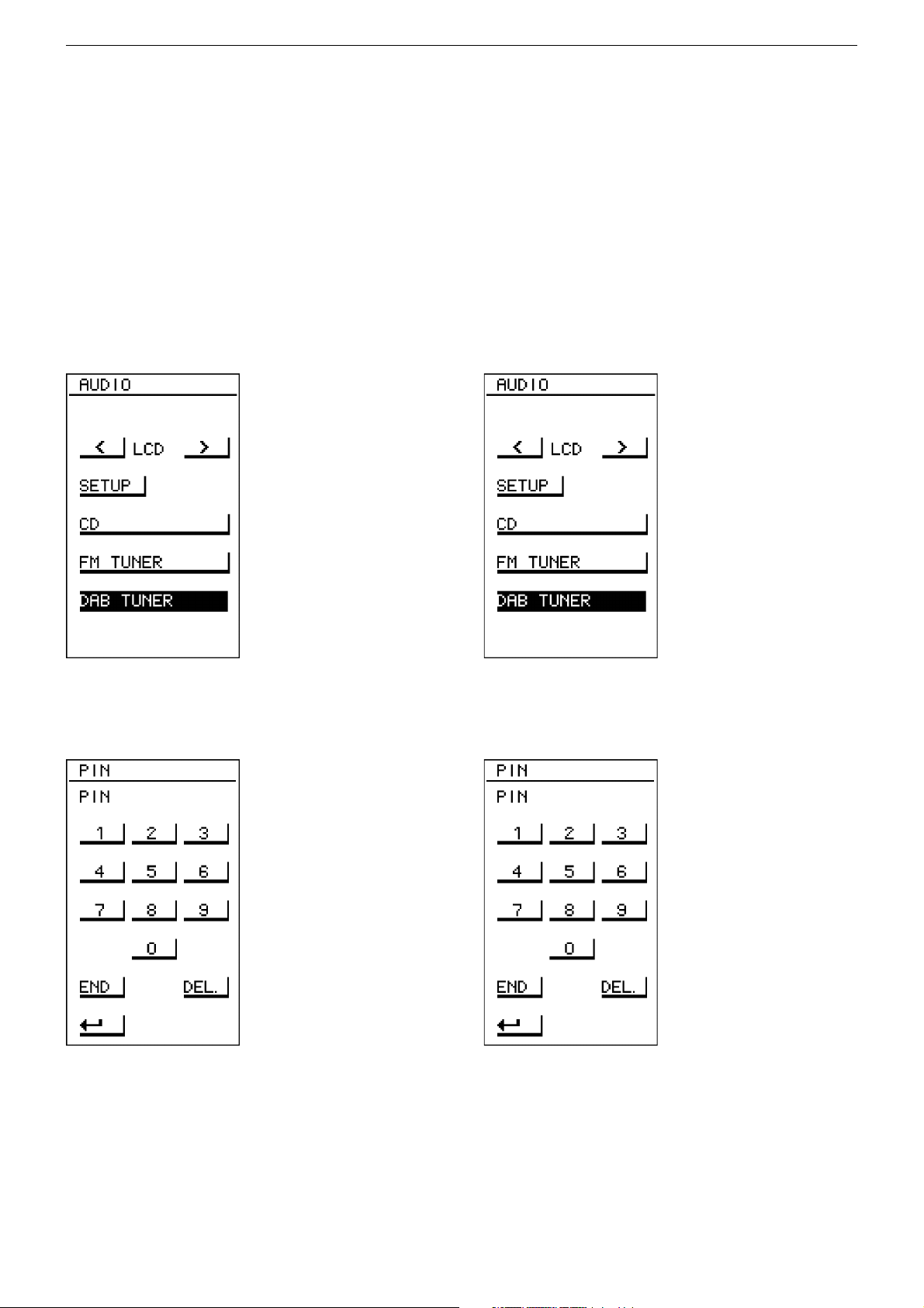
Ist die PR1 eingeschaltet, so wird mit der Taste [ AUDIO ] das AudioHauptmenü eingeblendet.
Service Functions PR1
1. Service Mode PR1
The service mode of the PR1 comprises the following functions:
- Contrast setting
- CCS mode (Customer Channel Select) for setting the audio channel
bundles
- Production mode for testing the display and touchpad function
- Inquiry of the HW and SW versions of the PR1
- Inquiry of the HW and SW versions of the LSP and WT2
1.2 Access to the Service Functions
Access to the service functions is possible in two ways. The first way
goes via the menu tree of the PR1. The second way is switching the
PR1 on via a certain key combination.
1.2.1 Access via the Menu Tree
If the PR1 is switched on, pressing the [ AUDIO ] button displays the
main menu.
Neben der Source-Auswahl und der Display-Steuerung für die RCD
8300 findet sich hier der Zugang zum Setup-Menü. Nach Betätigung
der Taste [ SETUP ] fordert die PR1 zur Eingabe einer PIN auf.
An dieser Stelle muss nun die Setup-PIN "1590" eingegeben und mit
[ END ] bestätigt werden. Ist die Eingabe korrekt, so zeigt die PR1 das
Setup-Menü.
Besides the source selection and the display control for the RCD 8300,
the setup menu can be accessed via this menu. After pressing the
[ SETUP ] button, the PR1 prompts to enter a PIN.
You now must enter the Setup PIN "1590" and then confirm it with
[ END ]. If the entry was correct, the PR1 will display the setup menu.
2 - 13
GRUNDIG Service Fine Arts Audion
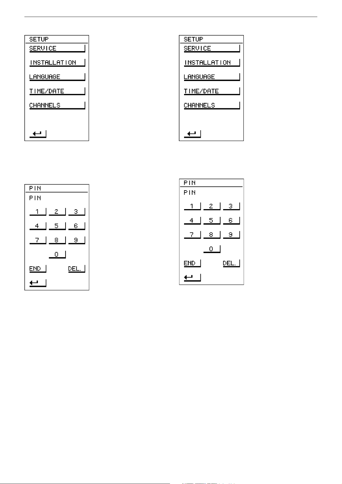
Im Setup-Menü können verschiedene Einstellungen vorgenommen
werden. Desweiteren liegt hier der Zugang zu den Servicefunktionen.
Nach Betätigung der Taste [ SERVICE ] fordert die PR1 erneut zur
Eingabe einer PIN auf.
An dieser Stelle muss die Service-PIN "8500" eingegeben und mit
[ END ] bestätigt werden. Ist die Eingabe korrekt, so zeigt die PR1 nun
das Service-Menü zur Auswahl der Servicefunktionen.
In the Setup menu, various settings can be carried out. The menu
provides also the access to the service functions. After pressing the
[ SERVICE ] button, the PR1 prompts again to enter a PIN.
You now must enter the service PIN "8500" and then confirm it with
[ END ]. If the entry was correct, the PR1 displays the Service Menu for
selecting the service functions.
1.2.2 Zugang über Tastenkombination
Der Zugang zum Servicemenü ist auch über das Einschalten der PR1
mit gleichzeitigem Drücken der Tasten [ ROT ] und [ OK ] möglich. Die
PR1 fordert daraufhin sofort zur Eingabe der Service-PIN auf (siehe
oben). Wird die Service-PIN "8500" eingegeben und mit
[ END ] bestätigt, so blendet die PR1 das Service-Menü ein.
Dieser Weg des Zugangs ist auch bei einer nicht-installierten PR1
möglich.
1.2.2 Access via a Button Combination
The Service Menu can also be accessed by switching the PR1 on while
simultaneously pressing the [ RED ] and [ OK ] buttons. The PR1 then
immediately prompts for the entry of the service PIN (see above). If the
service PIN "8500" is entered and confirmed with [ END ], the PR1 will
display the Service Menu.
This access mode is also possible if PR1 is not installed.
2 - 14
GRUNDIG Service Fine Arts Audion
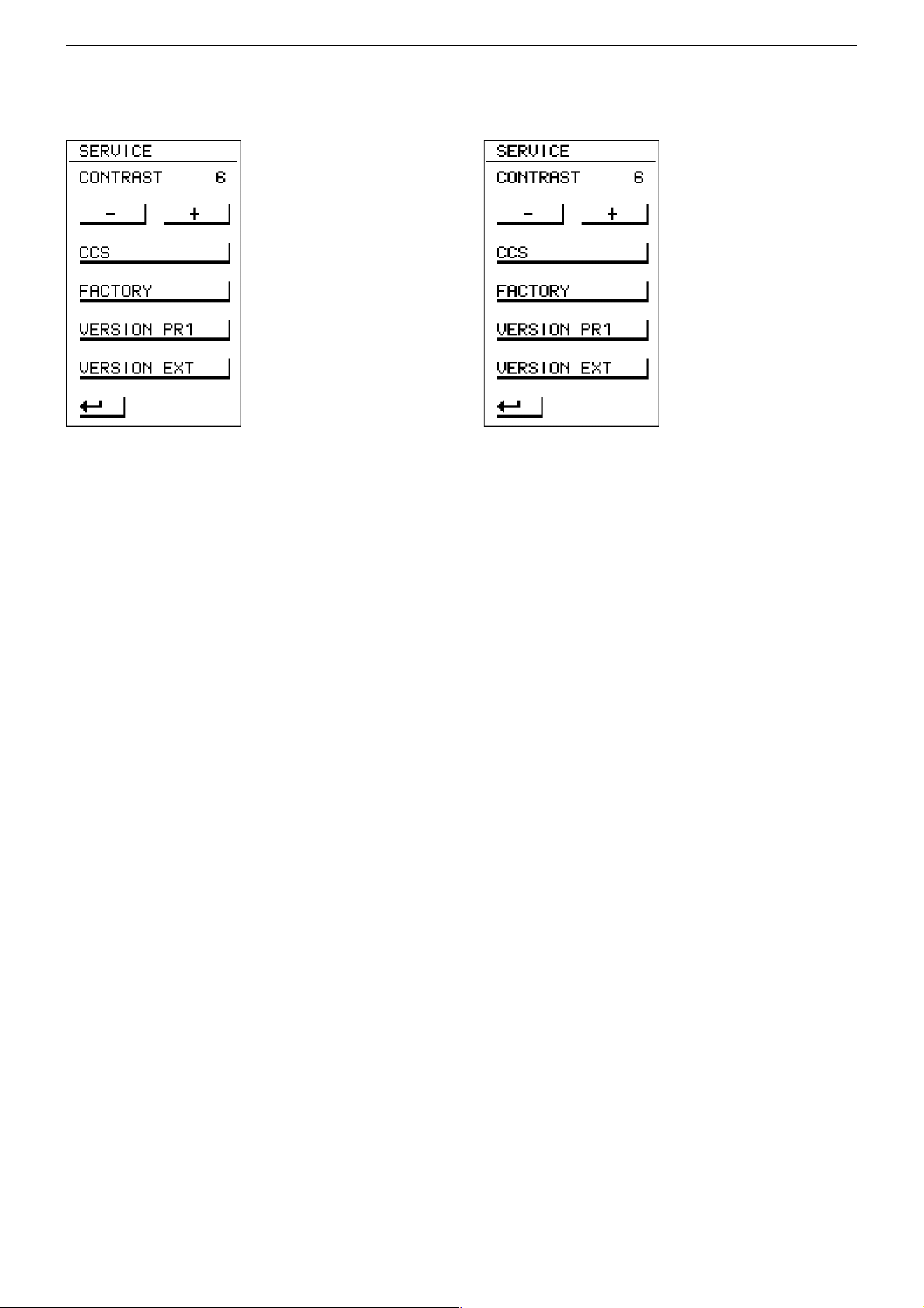
1.3 Auswahlliste (Menübaum)
Die folgende Abbildung zeigt das Service-Menü zur Auswahl der
Servicefunktion.
Hier kann der Kontrast geändert werden oder weitere Servicefunktionen
aufgerufen werden. Die Servicefunktionen sind im einzelnen:
- Einstellung des Kontrastes
- CCS-Modus (Customer Channel Select oder Kanalwahl-Verfahren)
zur Einstellung der Audio-Kanalbündel
- Fertigungsmodus zum Test von Display und Touchpad Funktion
- Abfrage von HW und SW Versionen der PR1
- Abfrage von HW und SW Verisonen von LSP und WT2
1.4 Beenden des Servicemenüs
Service-Menü wird durch Herausnehmen der Batterie beendet.
Beenden mit [ ↵ ] kann zu Fehlfunktionen führen.
Die Servicefunktionen CCS-Modus und Fertigungsmodus können nur
über das Herausnehmen der Batterien beendet werden, da hier ein
Verlassen des Modus über Tasten nicht vorgesehen ist.
1.3 Select List (Menu Tree)
The following figure shows the Service Menu for selecting the service
functions.
In this menu you can change the contrast setting and call up further
service functions. These are:
- Contrast setting
- CCS mode (Customer Channel Select) for setting the audio channel
bundles.
- Factory mode for testing the display and touchpad function.
- Inquiry of the HW and SW versions of the PR1.
- Inquiry of the HW and SW versions of the LSP and WT2.
1.4 Exiting the Service Menu
Remove the batteries to exit the Service Menu.
To end with [ ↵ ] may cause malfunctions.
The CCS- and production mode service functions can only be ended
by removing the batteries, as exiting these modes via a button
combination is not provided.
2. Beschreibung der Funktionen
2.1 Kontrast
Über die Tasten [ - ] und [ + ] kann der Kontrast geändert werden. Die
Einstellung des Kontrastes ist im Bereich von 0...11 möglich. Niedrigere Werte bedeuten schwächeren Kontrast, höhere Werte stärkeren
Kontrast. Voreingestellt ist hier Wert 6.
2.2 CCS
Über die Taste [ CCS ] wird die PR1 in den CCS-Modus (Customer
Channel Select oder Kanalwahl-Verfahren) versetzt.
2. Description of the Functions
2.1 Contrast
The contrast setting can be changed with the [ - ] and [ + ] buttons. The
contrast setting is possible in the range 0...11. Low values mean low
contrast and high values high contrast. The default setting is 6.
2.2 CCS
Pressing the [ CCS ] button switches the PR1 in the CCS mode
(Customer Channel Select).
2 - 15

GRUNDIG Service Fine Arts Audion
Der CCS-Modus ermöglicht die Messung der örtlichen Funklandschaft
und die Einstellung der optimalen Kanalbündel, die der Kunde später
über die Kanalwahl auswählen kann.
Im CCS-Modus dient die PR1 lediglich als Verbingungsglied zwischen
einem an die PR1 angeschlossenen PC und dem Audion-Systems.
Die gesamte Bedienung des CCS-Modus erfolgt dann über den PC.
Der CCS-Modus kann nur durch Herausnehmen der Batterien beendet
werden.
Weitere Information zu CCS gibt die Beschreibung zum CCS / Kanalwahl-Verfahren .
2.3 Fertigung
Über die Taste [ FACTORY ] wird die PR1 in den Fertigungsmodus
versetzt. Hier kann in mehreren Schritten die Funktion von Display und
Touchpad getestet werden. Die Schritte können über einen beliebige
Taste (Hardkey) weitergeschaltet werden.
Im einzelnen werden folgende Schritte angeboten:
1. Rahmen zeichnen – zum Test der Positionierung des Displays
2. Hintergrundbeleuchtung einschalten – zum Test der Funktion
3. Abwechselnd alle Pixel des Displays setzen und löschen – zum Test
auf Pixelfehler
4. Touchpad – zum Test der Funktion: wird eine Touchpad-Fläche
gedrückt, so erscheint die von der SW erkannte Position im Format
„Spalte/Zeile“ auf dem Display. Die oberste Zeile des Touchpads
wird hierbei nicht berücksichtigt, so dass sich eine Wertebereich von
0 bis 5 für die Spalten und von 1 bis 13 für die Zeilen ergibt. Es wird
immer nur eine Position gleichzeitig von der SW als erkannt deklariert. Wird eine Touchpad-Fläche in der oberen Hälfte des
Touchpads gedrückt, so erscheint die Position in der unteren Hälfte
des Displays und umgekehrt.
5. wieder bei 1. beginnen
Der Fertigungsmodus kann nur durch Herausnehmen der Batterien
beendet werden.
The CCS mode enables the measurement of the local radio environment and the setting of the optimum channel bundles that the customer
later can select via the channel select mode.
In the CCS mode, the PR1 serves only as link between a PC connected
to the PR1 and the audio system. The CCS mode then is completely
controlled via the PC.
The CCS mode can only be exited by removing the batteries.
For more information about the CCS mode, refer to the description of
the CCS / channel selection mode.
2.3 Factory
Pressing the [ FACTORY ] button switches the PR1 in factory mode.
In this mode, the function of the display and touchpad can be tested in
several steps. It is possible to press any button (hardkey) to switch to
the next step.
The following steps are provided:
1. Draw frame – for testing the display position.
2. Switch on background illumination – for testing the function.
3. Set and clear alternately all display pixels – for testing for pixel
failures.
4. Touchpad – for testing the touchpad function: if a touchpad area is
pressed, the position recognized by the SW appears in the „Column/
line" format on the display. The top line of the touchpad is not taken
into account resulting in a recognition range of 0 to 5 columns and
1 to 13 lines. The SW recognizes and displays only one position at
a time. If a touchpad area in the top part of the touchpad is pressed,
the position is displayed in the bottom part of the display, and vice
versa.
5. Restart with 1.
The factory mode can only be exited by removing the batteries.
2 - 16

GRUNDIG Service Fine Arts Audion
2.1 Version PR1
Bei Betätigung der Taste [ VERSION PR1 ] blendet die PR1 eine
Bildschirmseite ein, die alle relevanten Versionen enthält.
Dies sind im einzelnen:
1. HW: Version der eingesetzen PR1-Platine
2. SW: Version der im Flash des Prozessors abgelegten Software
3. DICT.: Version der im EEPROM abgelegten Sprachbibliothek
4. WLM: Version der WLM-Firmware
5. ADDR.: Adresse des eingebauten WLM
Mit der Taste [ ↵ ] kann zum Service-Menü zurückgekehrt werden.
2.1 Version Externe
Bei Betätigung der Taste [ VERSION EXT ] blendet die PR1 eine
Bildschirmseite ein, die alle relevanten Versionen eines externen
Gerätes enthält.
Die PR1 gewinnt die Informationen aus den Installationsdaten, die
eine LSP oder ein WT2 im Installationsmodus sendet. Dazu muss
dieses Gerät zunächst in den Installationsmodus gesetzt werden
(siehe auch Installationsanleitung des Audion Systems).
2.1 Version PR1
If the [ VERSION PR1 ] button is pressed, the PR1 displays a screen
containing all relevant versions.
These are in detail:
1. HW: version of the installed PR1 board.
2. SW: version of the software stored in the Flash of the processor.
3. DICT.: version of the language library stored in the EEPROM.
4. WLM: version of the WLM firmware.
5. ADDR.: address of the installed WLM.
Pressing the [ ↵ ] button returns you to the Service Menu.
2.1 Version Ext
If the [ VERSION EXT ] button is pressed, the PR1 displays a screen
showing all relevant versions of an external device.
The PR1 obtains this information from the installation data transmitted
by a LSP or a WT2 in the installation mode. For this, the device
concerned first must be switched in the installation mode (refer also to
the Installation Instructions of the audio system).
Folgende Informationen über das externe Gerät werden angezeigt:
1. DEV: LSP oder WT2
2. HW: Version der eingesetzten HW
3. SW: Version der im Speicher des Prozessors abgelegten Software
4. WLM: Version der WLM-Firmware
5. ADDR.: Adresse des eingebauten WLM
Mit der Taste [ ↵ ] kann zum Service-Menü zurückgekehrt werden.
The following information about the external device is displayed:
1. DEV: LSP or WT2.
2. HW: version of the installed HW.
3. SW: version of the software stored in the processor memory.
4. WLM: version of the WLM firmware.
5. ADDR.: address of the installed WLM.
Press the [ ↵ ] button to return to the Service Menu.
2 - 17

GRUNDIG Service Fine Arts Audion
Abgleichvorschriften
Tuner
Messgeräte: Mess-/Wobbelsender, Oszilloskop, Digital-Voltmeter, NF-Voltmeter, Klirrfaktor-Messgerät
Hinweis: Das Frontend ist ein komplett abgeglichener Baustein. Nur das ZF-Filter muß dem ZF-Verstärker angeglichen werden (1).
Die Abstimmspannungen des Frontends haben folgende Größen: 87,5MHz = typ. 1,6V min 1,3V; 108MHz = typ. 8,0V max 9V
Abgleich Vorbereitung Abgleichvorgang
1. ZF-Filter
Wobbelsender an Antennenbuchse.
Mittenfrequenz 98MHz.
∆f = ±100kHz; UHF = 100µV/ 75Ω.
Oszilloskop an MP1.
2. Demodulator
Mess-Sender 98MHz an Antennenbuchse.
UHF = 1mV / 75Ω, f
Klirrfaktor-Messgerät an MP2.
3. Feldstärke
4. 38kHz-Filter
Mess-Sender 98MHz an Antennenbuchse.
U
= 100µV / 75Ω.
HF
Digitalvoltmeter an MP5.
Mess-Sender an Antennenbuchse.
UHF = 1mV / 75Ω, f
NF-Voltmeter an MP2 (linker Kanal) bzw. MP3 (rechter
Kanal).
5. 19kHz-Filter
Mess-Sender an Antennenbuchse.
UHF = 1mV / 75Ω, f
NF-Voltmeter an MP2 (linker Kanal) bzw. MP3 (rechter
Kanal).
Adjustment Procedures
= 1kHz, Hub = 40kHz.
mod
= 38kHz, Hub = 40kHz.
mod
= 19kHz, Hub = 40kHz.
mod
Mit A auf Maximum und Symmetrie
einstellen.
Mit F141 B auf minimalen Klirrfaktor einstellen.
Mit P142 F 1,4V ± 0,05V einstellen.
Mit F171 I (linker Kanal) und F172 K (rechter Kanal)
Minimum einstellen.
Mit F171 G (linker Kanal) und F172 H (rechter Kanal)
Minimum einstellen.
Tuner
Test Equipment: Standard/sweep generator, Oscilloscope, Digital voltmeter, AF voltmeter, Distortion meter
Note: The frontend is a completely preadjusted module. Only the IF filter must be adjusted to the IF amplifier (1).
The values of the tuning voltages are as follows: 87.5MHz = typ. 1.6V min 1.3V; 108MHz = typ. 8.0V max 9V
Adjustment Preparation Adjustment Procedure
1. IF Filter
2. Demodulator
3. Field strength
4. 38kHz Filter
5. 19kHz Filter
Sweep generator to aerial socket.
center frequency 98MHz.
∆f = ±100kHz; URF = 100µV / 75Ω.
Oscilloscope to MP1.
Test generator 98MHz to aerial socket.
URF = 1mV / 75Ω, f
Distortion meter to MP2.
= 1kHz, Dev. = 40kHz.
mod
Test generator 98MHz to aerial socket.
U
= 100µV / 75Ω.
RF
Digitalvoltmeter to MP5.
Test generator to aerial socket.
URF = 1mV / 75Ω, f
AF voltmeter to MP2 (left channel) resp. MP3 (right
= 38kHz, Dev. = 40kHz.
mod
channel).
Test generator to aerial socket.
URF = 1mV / 75Ω, f
AF voltmeter to MP2 (left channel) resp. MP3 (right
= 19kHz, Dev. = 40kHz.
mod
channel).
Adjust A to maximum and
symmetry.
Adjust F141 B to minimum distortion.
Adjust P142 F to 1.4V ± 0.05V.
Adjust F171 I (left channel) and F172 K (right channel)
to minimum.
Adjust F171 G (left channel) and F172 H (right channel)
to minimum.
3 - 1

GRUNDIG Service Fine Arts Audion
Abgleichlageplan / Alignment Layout
Signal-Platte / Signal Board
114
MP3MP2
MP5
CR5
-+
CR6
CC6
CIC3
CC9
15 28
-+
A
FE100
IC120
B
F141
IC140
P141
F101
P142
F
F171
F172
IG
KH
F102
MP1
Beim Austausch eines der ZF-Filter (F101, F102) achten Sie darauf, dass nur
Filter mit gleicher Kennfarbe bestückt sind.
When replacing one of the ceramic resonators (F101, F102), take care that
the colour codes of all resonators are the same.
ZF (MHz)
IF (MHz)
10.6500 D schwarz / black
10.6750 B blau / blue
10.7000 A rot / red
10.7250 C orange
10.7500 E weiß / white
ZF / IF Filter
Kennbuchstabe
Ident. letter
ZF / IF Filter
Farbe / Colour
3 - 2

GRUNDIG Service Fine Arts Audion
Schaltpläne und Platinenabbildungen / Circuit Diagrams and Layout of the PCBs
Blockschaltbild RCD 8300 / Block Diagram RCD 8300
Spannungsvers.
Netzteil /
Power-
Management
Tastatur
Daten
Audio (Stereo)
HF
WLM TX 1 TX 2
Audio-Matrix
EEPROM
CD
D/A
Wandler
Uhr
Master-µC
Reset &
Taktgen.
Display
Open/Close
Sensor
Motore
Tray/Displ.
Netzschalter-Platte RCD 8300 / Mains Switch Board RCD 8300
Sicht auf Bestückungsseite / View on Component Side
MAINS
230V AC
50-60Hz
BU1
1
1
2
2
S1
ESB92S11B
SI01
T315mAL
F01
1
23
8140-601-177
4
28.02.01
ST2
1
2
EEPROM
Th.sw.
o
130 C
Slave-µC
Reset &
Taktgen.
DAB
FM
13,5V~
13,5V~
F01
SI01
T315mA-L
ST2
S1
59452-336.00
04
MI-
(04)4B
BU1
4 - 1
POWER TRANSFORMER
17,3V~
8.5V~
8.5V~
TO
Control Board
S/P 4-5

GRUNDIG Service Fine Arts Audion
CC214
C
U2
A
1
8
Steuer-Platte RCD 8300 / Control Board RCD 8300
18
17
16
15
14
13
12
11
10
9
8
7
6
5
4
3
2
1
JP6 (BU6)
zu / to JP5
S/P 4-10
10.1V
10.1V
10.1V
5.1V
5.1V
5.1V
5.1V
9.1V
0V
GND-FM
GND-TX
GND-DAB9
GND-NF
GND-DAB5
BC846B
B
100k
KK SK76
CT16
5
43
8
7
6
5
GND
10.1V
6.6V
9.6V
CC74
5V
POWER-ON
10k
CR357
C
E
CC63
GND
GNDGND
+8V-A
+8V-A
0.1uF/16V
0.1uF/16V
CTS
W
+
220R
CR349
CT17
BC857B
E
10k
CR353
B
C
CD42
CR354
100k
BZX84C3V3
CC219
+
10uF/16V
CR355
100k
CR356
VCC
SLV-RST
HANDSHAKE
SI0
SO0
SCK0
+5V-DIG
+5V-FM
+10V-NF
+5V-DAB
+10V-FM
+9V-TX
+10V-DAB
GND
+8V-A
SI6
F500mA/32V
CC17
GND
9.7V
POWER-ON
5V
0.1uF/16V
10k
CR46
GND
10.1V 10.8V
GND
DAB-ON
CR40
5.1V
5
1
CIC5
5.1V
2
LT1129CQ
43
GND
5V 5V
1
8
CIC6
2
7
LTC1155IS8
3
6
5V
4
10k
5V
5
5.1V
5.1V
+5V-DAB
S
+
10uF/35V
CR207
0.47uF/16V
CC75
GND
15k
+
10uF/35V
+5V-DIG
CD3
LS4148
100k
CR10
CR206
CR77
CR78
CT2
5k6
15k
D
BSP319
CD4
G
10.7V
BZV55C12V
100k
CR11
CC21
0.33uF/50V
GND
5.1V
1
CIC33
3.7V
2
5k6
LT1129CT
GND
5.1V
1
CIC15
3.7V
2
3
LT1121CS8
4
CC210
CD5
LS4148
CR12
100k
CC18
0.1uF/50V
GNDGND
D
CT3
CC22
GND
+
10uF/35V
G
10.6V
CC19
connection
GND
+5V-FM
5.1V5.1V
S
BSP319
0.33uF/50V
GND
CR8
0.1uF/16V
Net-
CD6
BZV55C12V
CR13
100k
Net-
connection
100k
CR9
CC20
100k
0.1uF/16V
VCC
GND-DAB5
CC64
GND
CC100
GND-FM
CR6
5k6/1%
CR7
15k/1%
GND
5.1V
FM-ON
10k
CR39
GNDGND
+12V
SI7
F500mA/32V
FM-ON
14.8V 10.1V
CC23
5V
0.1uF/16V
POWER-ON
GND
10V
1
22V
2
LTC1155IS8
3
GND
5V
Net-
connection
GND
5
1
CIC7
3.7V
LT1129CQ
2
43
GND
10V
8
CIC8
22V
7
6
DAB-ON
54
0V FM
5V DAB
GND-DAB10
CR14
CR15
GND
27k/1%
16k/1%
CC24
+10V-FM
LS4148
100k
CR18
CD7
D
CT4
CC27
GND
G
22.1V
10.1V10.1V
S
BSP319
CD8
0.33uF/50V
connection
GND
BZV55C12V
CR19
100k
Flash-Anschluss
Flash Connector
Net-
GND-FM
JP1 (ST1)
CC101
10
9
GND
8
7
6
5
4
3
2
1
+9V-TX
CC94
0.47uF/16V
U3
+
10uF/35V
GND
+
CR16
CC25
10uF/35V
CT5
CD9
LS4148
CR20
100k
0.1uF/16V
10.1V10.1V
+10V-DAB
S
D
BSP319
G
22.1V
CC28
GND
GND
100k
CD10
0.33uF/50V
CC26
BZV55C12V
CR21
100k
+10V-NF
100k
0.1uF/16V
CR17
Achtung: CCxx im Schaltplan = Cxx auf der Leiterplatte (z.B. CC28=C28)
Notice: CCxx in Circuit Diagram = Cxx on PCB (e.g. CC28=C28)
4 - 2

GRUNDIG Service Fine Arts Audion
U
CR147
CR318
CR80
GND
+9V-TX
GND
U3
CTS1
+
C
E
GND
WAKEUP
+8,2V-BL
CC214
U2
10uF/35V
CR45
4k7
C
E
GND
GND
U4
CT12
BC848B
BC848B
+
CR44
CT14
10uF/35V
4K7
CR326
U1
GND
6k8
B
CR49
220k
CR52
47k
C
B
E
CT13
47k
CR50
BC848B
GND
CR53
220k
CR56
B
47k
C
B
E
CT15
47k
BC848B
CR54
GND
8.2V
1
CIC60
LT1129CQ
2
5K6
CR327
GND
CL12
BLM11A102S
100pF
100pF
CC47
CC48
9.1V 14.9V
1
CIC18
3.7V
2
3
LT1121CS8
4
10k
CR61
GND
VCC
CR51
10k
VCC
CR55
10k
5
43
CC217
8
7
6
5
14.9V
5V
GND
5V
CR83
CR95
100pF
RTS
10k
10k
FLH-RES
10k
CC93
TX-ON
WAKE_UP
SI8
F500mA/32V
LCD-LIGHT
CC213
GNDGND
VCC
RXD0
VPP
TXD0
CR3
+12V
0.1uF/16V
GND
+12V
0.1uF/16V
+12V
CC83
0.1uF
GND
GND
RESET-LDC
CR303
LDR
5.1V
14
5.1V
13
5.1V
12
5.1V
11
5.1V
10
5.1V
9
5.1V
8
5.1V
7
5.1V
6
2.8V
5
2.9V
4
2.9V
3
2.9V
2
-17.6V
1
JP32 (BU32)
zu/to CBU123
S/P 4-23
10k
JP8 (BU8)
zu/to ST2
S/P 4-11
RESET_LCD
220R
CR94
100k
CR302
100k
CR301
GND
LCD-A0
LCD_CS\
LCD-RD\
LCD-WR\
-14V-LCD
LCD7
LCD6
LCD5
LCD4
LCD3
LCD2
LCD1
LCD0
CC67
10k
CR205
GND
47pF
CC66
2
3
1
2
3
4
5
6
7
8
9
10
11
12
CC65
47pF
6
5
-
+
47pF
CC99
-
+
GND
2.8V
5.1V
GND
CC98
+12V
+12V
1/2
LM2904D
TXD-WLM
VCC
47pF
CC96
GND
47pF
ON
CC95
47pF
1/2
LM2904D
CIC17
1
10k
GND
47pF
CC58
GND
CIC17
7
6k8
CR63
CR64
CC57
47pF
CR363
47pF
OP-CLOSE
TRAY-LED+
TRAY-LED-
VCC
CR321
10k
VCC
GND
JP11 (BU11)
zu / to JP2
S/P 4-24
VCC
VCC
CIC2
M24256MW6T
LCD4
LCD3
CR315
CR315
LCD5
CR315
8
7
6
54
GND
LCD6
CR315
LCD7
1k
4 X 1k Netz
22k
CR1
SDA0
CR319
CR2
SCL0
1
2
3
GND
5
5.1V
4
5.1V
3
11V
2
4.7V
1
TRAY-IN
CR312
4 X 1k Netz
LCD0
CR312
LCD1
CR312
LCD2
CR312
22k
LED1
LED2
CR79
22k
1k
LED2
LED1
VCC
SDA1
22k
1k
CR317
SCL1
656463626160595857565554535251
P61/A17
P51/AD9
P50/AD8
XT2
50
XT1
CR309
CR309
CR309
CR309
CC216
10k
CR320
VCC
100pF
49
P03/INTP2
48
47
P117(/CANRX1)
P116(/CANTX1)
46
P02/INTP1
45
P115/CANRX0
44
P114/CANTX0
43
P113
42
P112
41
P111
40
WAIT
39
38
VSS2
37
P107/KR7/TO1
36
P106/KR6/TI11
35
P105/KR5/TI10
34
P104/KR4/TO0
33
P103/KR3/TI01
32
P102/KR2/TI00
31
P101/KR1/TI70
30
P100/KR0/TO7
29
ASCK0
28
P14/SO1/TXD0
27
P13/SI1/RXD0
26
P01/INTP0
OP-CLOSE
CD-ON
WLM-ON
WAKEUP
LCD-LIGHT
POWER-ON
TRAY-ON
TX-ON
FM-ON
DAB-ON
GND2
GP0
LDR
CD20
CR358
3k9
LS4148
S1
CR364
6k8
KSR221J
GND
RXD0
TXD0
4 X 1k Netz
CTS1
CC53
1k5
CR359
47pF
CC52
47pF
1k5
CR361
47pF
1k5
CR362
CC54
12k
47pF
CC56
1k5
CR360
P04/INTP3
P110/
P15/SCK1
/
SCK0
/
SCL0
P12
P11/SO0
25 24 23 22 21 20 19 18 17 16 15 14 13 12 11
CR310
CR310
4 X 1k Netz
SI0
SO0
SCK0
4
GNDMRRESET
GND
VCC
MAX6806US46T
VCC
P10/SI0/SDA0
CR310
P52/AD10
VSS1
GND1
LCD-A0
CIC29
P54/AD12
P53/AD11
P47/AD7
P46/AD6
CR311
CR310
LCD-WR\
1
23
LCD-RD\
FLH-RES
P56/AD14
P55/AD13
P45/AD5
P44/AD4
CR311
CR311
LCD_CS\
CR100
1K
RESET-LCD
P60/A16
P57/AD15
UPD70F3079YGC8E
P43/AD3
P42/AD2
P41/AD1
CR311
4 X 1k Netz
RESET\
RESET_LCD
1
2
GND
VCC
14
7
P62/A18
CIC1
P40/AD0
560R
CR38
CC1
3
CIC4
74HC08
P64/A20
P63/A19
VPP/MODE
CLKOUT
RESET\
VPP
1
CQ1
33pF
GND
P65/A21
RESET
16MHz
4 - 3

0
u
/
6
P64/A20CLKOUT
CQ1
22k
GRUNDIG Service Fine Arts Audion
CD2000
TLMV3100GS08
CR37
1k8
LED2
CR66
1k8
LED1
VCC
22k
CR80
+
C211
0.22F/5.5V
GND
SDA1
SCL1
1k
CR3171kCR318
PORTVPP
4
LBEN
/
PORTVDD
P65/A21
P90
GC8EU
RESETX1X2
21110987654321
RESET\
0R
CR27
1M
CL11
16MHz
CR147
BLM11A102S
33pF
CC2
GND
GND GND GND
G
1
2
3
R
VCC
GND
CD2
LS4148
CR323
2.6V
5.1V
5.1V
UBEN
/
P91
8
7
6
PCF8593T
5
W
/
P92/R
470R
CIC3
/ DSTB
P93
PORTGND
PORTVSS
1
2
3
4
P94/ASTB
33pF
CC84
2.7V
4.5V
5.1V
RESET\
GND
7574737271706968676665
HLDRQ
HLDAK
/
/
P96
P95
ASCK1 SCK3
Q3
RXD1
P20
SI3/RXD1
S03/TXD1
32.768kHz
//
P05/INTP4/ADTRG
P23/SI4
P24/SO4
SCK4 /
P06/INTP5
P30/TI2/TO2
P31/TI3/TO3
P32/TI4/TO4
P33/TI5/TO5
P34/VM45/TI71
P07/INTP6
P70/ANI0
P71/ANI1
P72/ANI2
P73/ANI3
P74/ANI4
P75/ANI5
P76/ANI6
P77/ANI7
VDD
REGC
VSS0
P00/NMI
P83/ANI11
P82/ANI10
P81/ANI9
P80/ANI8
VCC
GND
33k
CR332
CC77
33pF
VDD0
0.1uF/16V
GND0
PD
GND
27k
CR333
GND
JP31(BU31)
zu/to CBU151
S/P 4-23
CIC4 CIC4 CIC4
P21
P22
P25
P26
P27
AVDD
AVSS
RXD1
KONTRAST
76
77
78
79
80
81
82
83
84
85
86
87
88
89
90
91
92
93
94
95
96
97
98
99
100
C
B
E
CT10
BC848B
GND
2.6V 2V
1
CIC9
2
GND
5.1V
3
MAX518BCSA-T
5.1V
4
CD-LAUFWERK
CD DRIVE
TRAY-OUT
TXD1
TRAY-IN
RTS1
4 X 1k Netz
CR313
CR313
CR313
CR313
CR314
CR314
CR314
4 X 1k Netz
CR314
1k
CR316
DISPE1
DISPE2
GND
CR173
1k
GND
1
2
3
4
5
8.1V
6
7
4,8V
8
0V
9
10
11
5.1V
C
E
CT11
BC848B
HANDSHAKE
P76
GND
P76
KEY0
CC220
CR43
220k
CR48
47k
8
7
6
5
TRAY-OUT
TRAY+
TRAY-
DISP+
DISP-
SLV-RST
ADCVDD
ADCGND
TRAYE1
TRAYE2
+8,2V-BL
+
B
CR166
GND
5.1V
GND
P70
GND
100uF/6,3V
CL13
10uH
47k
TRAYREF
VCC
ST2
CR47
10k
1
2
3
GND
SOUT-CD
SCLK-CD
CD-REQUEST
SRDY-CD
CD-RESET
GND
VCC
22k
CR325
CC212
GND
CR99
0.1uF
VCC
TXD-WLM
TXD1
10k
CR331
CC68
CC215
VCC
CR101
1k
1nF
VCC
CR59
CR60
GND
6k8
RXD
10k
1k
CR172
100pF
TRAY-IN
10k
KEY0
Net-
connection
ADCVDD
Net-
connection
PORTVPP
RTS1
CR57
CR58
GND
Net-
connection
ADCGND
Net-
connection
PORTGND
6k8
CTS
10k
GND2
GND1
GND0
Net-
connection
CC206
Net-
connection
Net-
connection
CC205
0.1uF/16V
CC204
0.1uF/16V
0.1uF/16V
CC207
GND
VDD0
CL10
VCC
BLM11P600SPM00-03
CC5
0.1uF/16V
0.1uF/16V
CC6
0.1uF/16V
CC7
0.1uF/16V
CC8
18
17
16
15
TRAY-IN
CD-REQUEST
SIN-CDSIN-CD
SOUT-CD
SCLK-CD
SRDY-CD
CD-RESET
CC92
CC51
CC89
100pF
100pF
100pF
CC91
CC90
CC88
100pF
100pF
100pF
GND
5.1V
+5V-CD
CC79
CC209
470nF/16V
GND
GND
GND
TRAY-ON
10k
CR42
5k6
+
10uF/35V
9.4V
22V
5V
CR84
3.7V
GND
15k
CR85
1
2
3
4
1
2
3
LT1121CS8
GND
CIC11
DIP8
LTC1155CS8
CIC16
DIP8
GND
CC87
100pF
8
7
6
5
8.8V
3.7V
CC86
100pF
22V
5V
8
7
6
54
CD-ON
+5V-CD
9.6V
5V
CD-ON
10k
CR41
GND
GP0
+8V-CD
CC29
CC78
GND
GND
+8V-B
GND
+
10uF/35V
10.5V
10.5V
5.1V
5.1V
9.5V
+8V-B
0.1uF/16V
CT8
CD15
LS4148
CR31
100k
0V
0V
0V
CC34
13
12
11
10
9
8
7
6
5
4
3
2
1
D
BSP319
CC37
JP4 (BU4)
zu/to BU1
S/P 4-24
CR25
0.1uF/16V
10.7V10.7V
G
22,6V
0.33uF/50V
GND
100k
S
CD16
CC35
BZV55C12V
CR32
100k
14
0V
DISP-
DISP+
100k
0.1uF/16V
+8V-CD
CR28
CR70
68k
CR69
68k
TRAY+
TRAYREF
TRAY-
CD13
LS4148
100k
CR29
connection
GND
C123
CD36
LS4148
CD37
LS4148
D
CT7
Net-
CC36
GND
CR71
+
220uF/16V
GND
+8V-MOT
G
21,6V
1k2
+8V-MOT
CC72
CR198
100k
CR202
6k8
CR201
6k8
CR199
100k
9.7V9.7V
S
BSP319
CD14
100k
CR30
0.33uF/50V
GND-MOT
0.1uF/16V
BZV55C12V
V
1
F
.1
4 - 4

GRUNDIG Service Fine Arts Audion
CC8
+8V-MOT
0.1uF/16V
98
k
02
01
99
k
0.1uF/16V
CC9
0.1uF/16V
1
2
3
4
TDA7073A/AT
5
6
7
Net-
connection
GND
TRAYE1
CC10
CIC24
GND
1
2
3
CC11
0.1uF/16V
GND-MOT
CIC23
MAX4377TASA
CC12
0.1uF/16V
Display Motor
16
15
14
GND
13
12
11
10
GND
98
+
47uF/16V
CR120
470m
DISPE1
CC13
8
7
6
54
+
CR203
270m
TRAYE2
CC14
47uF/16V
VCC
GND
+
47uF/16V
1
2
1
2
3
CC76
+
Blockkond.
CIC29/2/9/4
47uF/16V
JP 9(ST9)
zu/to Display Motor
CIC25
MAX4377TASA
JP10 (ST10)
1
2
Tray Motor
8
7
DISPE2
6
54
VCC
JP7(ST7)
Netztrafo
Power Supply
~13.5V
~13.5V
~17.3V
~8.5V
~8.5V
T630mAL/250V
1
2
3
4
5
6
7
8
SI3
SI4
T630mAL/250V
T50mAL/250V
T2AL/250V
GND
SI1
T2AL/250V
CC39
CC40
SI5
SI2
CD18
CC55
GND
100R
1N4004
0.1uF/50V
GND
0.1uF/50V
1N4004
CC59
CC60
CR23
CD17
LS4148
+
1uF/50V
D28
D29
100R
22K
0.1uF/50V
GL2
0.1uF/50V
DF02S
0.1uF/50V
CC45
CC46
CR22
LS4148
CR4
47k
CR33
BLM21P220SG
CC81
BLM21P220SG
CC80
0.1uF/50V
0.1uF/50V
0.1uF/50V
5.76V
CL4
CL5
0.1uF/50V
B
BC848B
CC61
CC62
D30
1N5401G
CC200
0.1uF/50V
CC201
0.1uF/50V
D31
1N5401G
D32
1N4004
D33
1N4004
CC203
CT1
14.9V
2200uF/25V
C38
GND
0.1uF/50V
0.1uF/50V
CC202
0.1uF/50V
VCC
5.16V
C
5.14V
E
18k
CR5
GNDGND
+12V
+
0.1uF/50V
CC32
21.3V
CL6
BLM21P220SG
CL7
BLM21P220SG
BLM21P220SG
CC16
GND
RESET-LCD
CR24
CD19
LS4148
+
100uF/35V
+
C31
9.8V
CL8
BLM21P220SG
CL9
+
C50
2200uF/25V
CR330
1k
0.1uF/16V
CC41
C44
CC49
CC15
GND
47k
10u/35V
0.1uF/50V
+8V-A
GND
GNDGND
CR329
CC4
+
CC43
4700uF/25V
+8V-B
0.1uF/50V
PD
0.1uF/16V
120R
GND
CR36
CD21
56k2
0.1uF/50V
KONTRAST
LS4148
-19.6V
120R
CR322
-17.6V
-3.8V 0V
CD40
MMSZ5249B
GND
1
8
7
6
5
-14V-LCD
CR34
4.8V
CR35
CIC12
2
DIP8
LT1175
3
4
11k/1%
CC85
30k/1%
1uF/25V
CD41
GND
LL4148
100k
R30
ND-MOT
BZV55C12V
28.01.03
4 - 5

Steuer-Platte RCD 8300 / Control Board RCD 8300
Sicht auf Bestückungsseite / View on Component Side
4 - 6
GRUNDIG Service Fine Arts Audion
Achtung: CCxx im Schaltplan = Cxx auf der Leiterplatte (z.B. CC28=C28)
Notice: CCxx in Circuit Diagram = Cxx on PCB (e.g. CC28=C28)

GRUNDIG Service Fine Arts Audion
Steuer-Platte RCD 8300 / Control Board RCD 8300
Koordinaten der Bauteile / Coordinates of Components
Pos.-Nr./ Koordinaten/
Pos. No. Coordinates
XY
C1 68 9
C2 60 13
C4 99 92
C5 116 38
C6 19 60
C7 31 37
C8 41 104
C9 29 78
C10 107 13
C11 104 32
C12 143 51
C13 92 50
C14 23 12
C15 58 17
C16 105 61
C17 154 13
C18 155 8
C19 185 3
C20 162 13
C21 138 20
C22 180 14
C23 184 41
C24 188 39
C25 180 32
C26 184 32
Pos.-Nr./ Koordinaten/
Pos. No. Coordinates
XY
C66 40 59
C67 38 57
C68 41 25
C72 52 81
C74 130 39
C75 133 52
C76 17 51
C77 62 16
C78 26 78
C79 48 63
C80 114 70
C81 110 70
C83 145 44
C84 23 34
C85 93 81
C86 62 60
C87 67 60
C88 64 60
C89 70 60
C90 72 60
C91 77 60
C92 78 60
C93 145 41
C94 148 28
C95 48 59
Pos.-Nr./ Koordinaten/
Pos. No. Coordinates
XY
D14 46 72
D15 85 69
D16 83 74
D17 95 70
D18 98 70
D19 105 80
D20 154 32
D21 87 87
D28 123 72
D29 119 66
D30 117 99
D31 118 94
D32 117 105
D33 130 105
D36 62 67
D37 70 66
D40 110 81
D41 93 87
D42 29 32
D2000 73 102
F1 144 102
F2 144 92
F3 133 76
F4 135 96
F5 137 86
Pos.-Nr./ Koordinaten/
Pos. No. Coordinates
XY
JP31 32 52
JP32 50 52
L4 128 69
L5 128 58
L6 109 87
L7 109 90
L8 113 102
L9 125 102
L10 67 11
L11 62 13
L12 23 74
L13 28 57
Q1 47 15
Q3 23 30
R1 40 46
R2 37 46
R3 26 74
R4 102 65
R5 105 63
R6 154 4
R7 151 4
R8 183 3
R9 164 13
R10 142 18
Pos.-Nr./ Koordinaten/
Pos. No. Coordinates
XY
R47 103 43
R48 105 46
R49 96 22
R50 107 23
R51 111 20
R52 102 18
R53 96 34
R54 107 34
R55 112 31
R56 102 29
R57 86 36
R58 88 36
R59 54 35
R60 52 35
R61 142 32
R63 91 32
R64 93 32
R66 67 95
R69 50 83
R70 44 83
R71 47 83
R77 137 47
R78 134 47
R79 43 27
R80 43 30
Pos.-Nr./ Koordinaten/
Pos. No. Coordinates
XY
R320 52 62
R321 44 104
R322 117 80
R323 17 42
R325 34 57
R326 197 39
R327 200 36
R329 119 76
R330 102 62
R331 48 25
R332 55 18
R333 57 18
R349 18 20
R353 13 42
R354 26 27
R355 29 27
R356 30 23
R357 26 16
R358 154 38
R359 58 59
R360 55 63
R361 60 56
R362 56 65
R363 52 66
R364 119 34
C27 189 19
C28 181 28
C29 41 98
C31 101 100
C32 126 65
C34 36 84
C35 34 89
C36 42 82
C37 76 66
C38 137 63
C39 126 75
C40 110 66
C41 99 77
C43 83 89
C44 71 85
C45 129 97
C46 129 94
C47 22 60
C48 20 62
C49 93 104
C50 85 98
C51 74 60
C52 59 59
C53 59 63
C54 56 59
C55 104 69
C56 54 59
C57 51 59
C58 50 59
C59 124 80
C60 117 84
C61 127 79
C62 117 88
C63 20 78
C64 15 76
C65 41 59
C96 46 59
C98 44 59
C99 43 59
C100 131 44
C101 144 35
C123 58 80
C200 104 90
C201 104 87
C202 117 102
C203 131 102
C204 65 14
C205 61 40
C206 90 34
C207 86 50
C209 39 72
C210 160 4
C211 89 60
C212 36 57
C213 193 39
C214 201 41
C215 32 44
C216 62 56
C217 29 74
C219 35 22
C220 34 62
D2 20 39
D3 145 19
D4 148 19
D5 178 8
D6 174 8
D7 163 18
D8 166 18
D9 163 28
D10 166 28
D13 43 72
F6 123 51
F7 105 58
F8 100 48
GL2 124 86
IC1 72 26
IC2 38 40
IC3 25 39
IC4 88 12
IC5 150 10
IC6 184 10
IC7 181 38
IC8 188 30
IC9 38 30
IC11 41 89
IC12 98 85
IC15 136 42
IC16 34 70
IC17 136 34
IC18 149 38
IC23 151 52
IC24 51 90
IC25 60 92
IC29 98 12
IC33 11 86
IC60 197 33
JP1 23 69
JP2 152 68
JP4 74 53
JP6 43 6
JP7 153 87
JP8 118 61
JP9 65 103
JP10 160 53
JP11 36 100
R11 142 21
R12 175 13
R13 177 13
R14 184 35
R15 184 38
R16 178 32
R17 182 32
R18 186 21
R19 186 18
R20 178 28
R21 177 28
R22 92 76
R23 103 73
R24 105 77
R25 34 84
R27 62 10
R28 36 89
R29 40 83
R30 40 77
R31 81 67
R32 82 70
R33 105 65
R34 90 85
R35 90 87
R36 89 82
R37 71 95
R38 87 7
R39 187 15
R40 180 7
R41 45 95
R42 44 86
R43 114 49
R44 147 32
R45 149 32
R46 132 39
R83 195 39
R84 43 67
R85 40 67
R94 129 35
R95 29 76
R99 46 30
R100 82 10
R101 82 39
R120 48 100
R147 68 7
R166 105 43
R172 32 43
R173 54 20
R198 58 70
R199 65 72
R201 63 72
R202 61 70
R203 152 59
R205 140 37
R206 13 70
R207 13 67
R301 137 53
R302 137 49
R303 140 34
R309 87 20
R310 80 13
R311 75 13
R312 79 39
R313 59 34
R314 59 30
R315 76 43
R316 51 26
R317 42 21
R318 43 33
R319 61 44
S1 17 56
T1 97 64
T2 155 19
T3 167 8
T4 171 17
T5 171 27
T7 52 73
T8 73 72
T10 110 49
T11 110 44
T12 97 18
T13 107 18
T14 97 30
T15 107 30
T16 31 18
T17 18 26
X1 17 62
X2 22 63
X3 32 74
X4 20 75
4 - 7

4 - 8
GRUNDIG Service Fine Arts Audion

GRUNDIG Service Fine Arts Audion
G
G
V
Signal-Platte RCD 8300 / Signal Board RCD 8300
JP4
3
2
1
8290-175-330
DAB-MODUL (DAB 300)
12060-100-00
SCLK
SDWSSPDIF
9
8
7
6
5
4
74HC00
DAB-TXD
11
10
CIC4
DAB-RXD
RDC
RDO
13
12
CL5
BLM11A102S
CC40
CIC4
74HC00
DAPITXD
RESET*
15
14
CL4
BLM11A102S
CR4
100P
GND
CC41
GND
CE
MUTE
OUT_1
DAPIRXD
17
16
CR50
1K
CC97
GND
100P
DAB-ST-R
CL
A_GND
A_GND
DAB_ST_REQ
RAUDIO
21
20
19
18
GND
1K
DAB-NF-R
100P
680R
CR41
CC95
1N
CR43
unbest.
GND
DATA-IN
DATA-OUT
A_GND
LAUDIO
23
22
GND
DAB-NF-L
680R
CR42
CR44
unbest.
GND GNDGND
STEREO
RDS-DATA
VCC/5V
24
CC13
GND
+5V-DAB
CC96
VCC/5V
25
GND
100P
CC91
1N
D_GND
D_GND
27
26
CC12
GND
+10V-DAB
10P
CC92
RDS-CLK
VCC/9V2
VCC/9V2
PHANTOM
30
29
28
100P
1N
CC93
GND
OUT_L
OUT_R
T_GND
31
GND
100N
T_GND
32
FIELDST
DAB-ANT
JP12
zu / to BU3
S/P 4-24
+10V-NF
+10V-NF
CR20
CR26
68K
CR82
3K9
CC50
270P
GND
CC80CC70
CR81
3K9
2.6V
CD_L-
1
CD_L+
2.6V
2
3
2.6V
4
2.6V
5
C
68K
CT1
C
BC847C
B
CT2
BC847C
B
E
CC30
+
10U/16V
CLK-TX
CD_R-
CD_R+
E
CC33
+
10U/16V
GND
DATA-TX
GND
GND
TX-E3
TX-E4
TX-E2
CR90
7K87
CR70
3K9
GND
CR71
3K9
TX-E1
CR91
CC52
270P
7K87
CR75 CR85
GND
CC94
MV4
MV5
10N
GND
GND
CR59
GNDGND
100R
+5V-FM
+10V-FM
Flash-Anschluss
Flash Connector
GND
VCCA
CC23
BLM11P600S
+
100U/16V
100p
CC42
TUNER
CC43
GNDGND
100p
FLH-RES
siehe Seite / see Page 4-12
VCC
CL1
100N
CC24
VCC
GNDGND
JP10
GND
10K
CR12
10
9
8
7
6
5
4
3
2
1
CR3
100P
CC98
GND
CC99
GND
100P
10K
100P
CC45
GND GND
GND
U2
CR5
CR6
GND
GND
GND
CC46
5K1
5K6
GND
U1
U3
GND
100P
JP1
1
2
3
4
Flash-Anschluss
Flash Connector
5
6
7
U4
8
9
10
4 - 9

GRUNDIG Service Fine Arts Audion
T
5
JUMPER
FLH RES
CR80
2
3K9
0
CR83
3K9
P
330P
CC80
1
CR84
3K9
7K87
330P
7K87
CC51
GND
CR72
3K9
CR73
3K9
CR74
3K9
CC53
GND
270P
270P
CC81
GND
CC71
GND
7K87
CR85
GND
0
2
P
CC70
1
CR75
GND
+10V-NF
180P
180P
CC82
180P
CC56
100N
CIC70
LM324A
CIC70
LM324A
GND
CR87
CR76
1K2
1K2
CR77
GND
CR86
GND
2K2
2K2
VCC
4U7/25V
CC25
4U7/25V
GND
CC9
+
+
CC10
4U7/25V
CR10
10K
CC54
100P
CR9
10K
GND-NF
GND-NF
GND-NF
GND-NF
AUDIO-B1
AUDIO-A2
AUDIO-A1
ST1
3
2
1
1516171819202122232425262728
ROUT2
LOUT2
4.7V4.7V
ROUT1
LOUT3
4.7V
ROUT3
R6
4.7V
R5
4.7V
4.7V
GND
5.1V
5.1V
CC55
100P
R4
R3
R2
R1
ADR
SCL
SDA
CIC3
TEA6422
GND
GND
+
CR57
CR58
1K
1K
LOUT1
GND
4.7V
L6
L5
L4
L3
L2
4.7V
L1
9.5V
V
4.7V
C
1234567891011121314
4.7V
4U7/25V
GND
4.7V
4U7/25V
CC11
+
4U7/25V
+
GND
CC5
GND GND GND
CC6
+
CC7
+
+
CC3
22U/25V
+10V-NF
CC4
47U/16V
3
ST8
JUMPER
1
100N
2
7
6
5
4
GND
1
2
GND
3
-
+
GND
CC72
180P
-
+
VCC
VCC
VPP
CC22
GND
CC21
GND
GND
100N
100N
0V
CC68
GND
1
CC69
5.1V
GND
100p
4
2
CIC5
GNDMRRESET
MAX6808
VCC
CIC4
14
74HC00
7
GND
CL7
BLM11P600S
4
3
HANDSHAKE
CC47
100p
GND
CC49
100p
CC48
GND GND
CR53
1K
5
100p
1
23
74HC00
6
5.1V
VCCA
100p
CIC4
7
5.1V
10.1V
CD4
+5V-FM
CC1
GNDGND
33P
Q1
CC2
33P
JP5 zu / to JP6 S/P4-2
9
8
5.1V
US1K
+10V-NF
+5V-DAB
10
10.1V
CR30
1K
CR31
1K
+10V-FM
11
9.1V
CD3
+9V-TX
CR32
1K
12
10.1V
US1K
+10V-DAB
CR30
VCC
GND
1K
GND
16MHz
13
GND
CR30
1K
CR31
14
GND
1K
47K
10K
CC18
100N
CR7
15
GND
CR25
1K
CR31
1K
OUT_R
CR51
CR52
VCC
CL2
BLM11P600S
1M
GND
CL6
BLM11A102S
CR11
560
17
16
GND
GND
CR31
1K
CR32
1K
SI0
SO0
SCK0
100N
18
GND
CC8
CR8
0R
GND
GND
CR32
1K
GND
SDA1
SCL1
CL
CIC1
39
FIELDST
1K
1K
CR35
40
41
MUTE
CR35
1K
42
DATA-OUT
1K
CR35
43
DATA-IN
CR35
1K
44
1K
CR34
45
VCC
CC19
GND
100N
GND
99989796959493929190898887868584838281
100
30 27 26 25 24 23 22 21 20 19 18 17 16 15 14 13 12 11 10 9 8 7 6 5 4 3 2 1
33
32
31
GND
ICQFP100
38
37
36
35
34
GND
S1
GND
CE
CR34
1K
STEREO
1K
CR34
47
46
CR34
HANDSHAKE
49
48
RDS-CL
1K
CR33
50
OUT_L
SDA1
SCL1
DAB-RXD
DAB-TXD
RDS-DATA
807978777675747372717069686766656463626160595857565554535251
CR33
1K
CR33
1K
DAB-ST-R
GND
VCC
CC66
100N
CR2
22K
CR23
1K
CR1
22K
GND
CR66
1K8
CR24
1K
LED2
LED1
SCL0
SDA0
VCC
8
VCC
5
SDA
CIC2
6
M24256
SCL
CR22
1K
1K
CR32
123
GND
VSA2A1A0
4 - 10

GRUNDIG Service Fine Arts Audion
6
GND
GND NF
TX-4 MODUL
CTS
14
GND
15
100P
GND-TX
RXD
18
17
16
GND
CL3
BLM21PG331SN1
WAKEUP
7
100P
TXDONATS
CLK
9
8
CC64
GND
CLK-TX
E3
10
CC65
100P
TX-E3
13
12
11
CC67
100P
GND
ONPWR
DATA
GND-NF
E4
E1
+9V-TX
ST3
CC60
GND
E2
1
100P
CC61
TX-E2
2
GND
+9V-TX
3
100P
TX-E1
4
GND
CC62
GND
TX-E4
5
100P
6
CC63
GND
DATA-TX
ONPWR
GND-NF
AUDIO-B2
8
7
D
1
ST9
JUMPER
3
SDA1
SCL1
ONPWR
GND-TX
ST2 zu / to JP8 S/P4-3
ST2
2
1
3
12
11
10
9
8
7
6
5
4
3
CR66
1K8
VCC
1
VCC
CC
CC15
100N
8
CC
C2
TEST
4256
VSSA2
234
CR65
1K8
7
RG1
3
GNDGND
GND
CD2
TLMV3100
2
22.08.02
4 - 11

GRUNDIG Service Fine Arts Audion
4
C
2
4
Signal-Platte (FM-Tuner) RCD 8300 / Signal Board (FM Tuner) RCD 8300
4N7
C101
R103
33K
R104
22K
GND GND GND
ANT/CABLE
R102
2K2
GND GND
T101
BC848B
C121
39P
C122
39P
A1
A2
GND
BAV102
D1
FM-ANT
D2
GNDGND
1
BAV102
2
4
GND
3
6K8
6K8
R101
R100
C100
GND
5
6
100N
GND
+10V-FM
VT
GND
GND
C123
21
22
23
24
2.6V 0.5V 5.1V 2.5V 8.1V
Q120
7.2MHz
2.3V 0.1V
123456789
+5V-FM
10K
R132
+5V-FM
100N
20
FM-OSZ
+5V-FM
47K
19
LC7218MIC120
18
IF-ENA
R124
17
FM-IF
+10V-FM
16
R123
15
101112 13
MO/ST
GND
GND
D126
LL4148
GND
47K
+5V-FM
14
PLL SYNTHESIZER
AND IF COUNTER
R126
100K
R127
100K
R128
100K
R129
47K
R133
2K2
DATA-IN
FE100
FM-FRONT END
CL
DATA-OUT
CE
+10V-FM
C135
100N
R137
LOOP-FILTER
2K2
GND
R136
8K2
T131
C134
1N
C133
F
470N
2SK30AY1
470R
R134
R138
GNDGND
VT
4K7
R139
T132
BC848C
MO/ST
IF-ENA
4K7
+10V-FM
FM-IF
+10V-FM
STEREO
+5V-FM
GND
B
C144
1N
C147
+
1U/50V
R149
R146
GND GND
6K2
F
100K
47K
GND
R189
C141
GNDGND
47N
47U/16V
+
C142
C143
100N
R142
4K7
100R
67
8141-111-450F141
R143
C146
10K
+
U47/50V
R148
6K2
C148
+
1U/50V
P14
P1
GND
R141
4 - 12

GRUNDIG Service Fine Arts Audion
+10V-FM
A
R106
7
100R
8602-822-070
1
F101
1K2
R108
3
2
560R
R107
R109
R111
R112
100N
C103
330R
T102
BF840
4R7
C102
330R
GND
F102
8602-822-070
1
2
22N
GNDGNDGNDGNDGND
MP1
3
+10V-FM
+
10U/16V
GND GND
+5V-FM
C113
C112
100N
470/16V
+10V-FM
zu / to Tuner
S/P4-9
+5V-FM
+
100N
C116
C117
GNDGND
CE
DATA - OU T
CL
L101
8
330N
MP5
DATA - IN
SEARCH-LV
FIELDSTG
STEREO
zu / to Tuner
S/P4-9
MUTE
RDS-CLK
RDS-DATA
FM-OSZ
FM-IF-IN
CL
CE
DATA-IN
DATA-OUT
SEARCH-LV
STEREO
FIELDSTG
MUTE
RDS-CLK
RDS-DATA
FIELDSTG
C140
+
4U7/35V
C149
22N
1
2
3
4
5
GND
6
7
8
9
10
11
12
141
13
14
15 16
STEREO DECODER
100KP142
n.b.P141
3.5V
3.5V
IC140
LA1837M
10.1V
4.0V
9V
9V
WITH FM-IF
GND GND GND GND
+5V-FM
22UH
L181
RDS DEMODULATOR
C181
GND
560P
876 543
2.5V
2.5V 5.1V 2.2V 2.5V
15
SAA6579TIC180
5.1V 2.1V 2.5V 2.5V
GNDGNDGND
47P
F171
12
8141-910-062
6
C182
R174
C187
2
100N
5
4
100R
3
2
197
4
5
8
12
GI
F172
8141-910-062
6
R173
GNDGNDGNDGND
3K3
MPX-FILTER
R177
100R
3
197
8
3K3
R176
HK
GNDGND GND GND
Q181
4M332
FM-MPX
R188
C186
R184
C183
GNDGNDGND
4K7
330P
MP3
GND
C184
2K2
82P
+
MP2
1614139101112
2U2/50V
2
1
OUT_L
OUT_R
RDS-DATA
10K
R186
zu / to Tuner
S/P4-9
RDS-CLK
10K
R187
FM-IF-IN
SEARCH-LV
T151
BC848B
FM-MPX
+10V-FM
MPX-BUFFER
18K
R153
R150
30
1.6V
29
28
3.6V
27
R160
26
5.1V
25
24
23
3.7V
22
2.8V
21
20
19
4.3V
18
4.3V
17
4.3V
4.3V
6K2
47N
3K3
C160
C170
+
4U7/35V
C154
1N5/5%
C153
C150
47N
GNDGND GND
GND
C188
+
33U/10V
C158
+
10U/16V
C156
10U/16V
C152
+
C180
+
10U/16V
+
C151
10U/16V
GND
GND
C157
560P/5%
100P
GND
GND
1N5/5%
470K
R161
LEFT
RIGHT
R156
1K2
R162
1K
D161
1U/50V
GND
R171
3K3
R172
3K3
GND
LL4148
+
C161
MUTE
R166
R164
R163
GNDGND
100K
100K
100K
MUTING
T161
BC848B
+10V-FM
R167
LL4148
150R
D162
T162
BC858B
R168
2K2
R169
2K2
C171
+
4U7/35V
C172
+
4U7/35V
T163
BC848B
GND
T164
BC848B
GND
4 - 13
22.08.02

0
0
10
20
30
40
50
60
70
80
90
10 20 30 40 50 60 70 80 90 100 110
120
130
140
150
160
170
180
190
200
210
220
230
240
Y
X
CR41
8
1
CIC70
CR44
-+
C140
32
31
2
1
JP4
-+
CC3
CL1
18 1
JP5
S1
CIC5
51
JP12
-+
CC10
-+
CC9
-+
CC11
-+
CC7
-+
CC25
CR74
-+
CC6
CD2
-+
CC23
-+
C142
-+
C188
CR73
CR72
CR81
CR70
CR71
CR83
CR84
CR82
CR80
CR75
CR76
CR85
CR77
CR86
CR87
CR8
CR6
CR4
CR2
CR1
CR3
CR66
CR65
CR11
CR5
CR7
CR42
CC40
114
15 28
CIC3
CR59
CR12
2
9
10
1
JP10
7
8
2
1
ST1
CR10
CR9
CC72
CC82
CC81
CC80
CC70
CC71
CC19
CC18
CC8
CC4
CC21
CC1
CC2
CC22
CC66
CC13
CC15
CC12
CC24
A2
A1
IC120
FE100
F141
F102
F101
IC140
C133
DS
T131
-+
C170
CR58
-+
C147
-+
C148
-+
C158
-+
C156
-+
C151
-+
C152
-+
C146
-+
C172
-+
C171
-+
C184
CC41
C123
R150
C116
C112
R156
C144
R143
R149
R142
R141
R146
R189
C141
R153
C157
C153
C154
C143
R112
R111
R109
R108
R107
C102
R172
R171
R161
R162
R167
R164
R163
R169
R168
R176
R177
R174
R173
R187
R186
C187
R188
C186
C181
C183
C182
R184
R123
R139
R138
R137
R136
R133
C134
R134
R132
R129
R128
R127
R124
R126
R160
C150
C160
C122
C121
R106
R104
C101
R103
R102
R100
R101
C149
R148
R166
C100
C103
C135
CR90
CR43
D126
D1
D2
D161
IC180
F172
F171
P141
P142
-+
C117
L101
Q181
Q120
-+
CC33
T164
T163
T132
T101
T162
T102
T161
CC94
17
18
2
1
ST3
CC91
CR91
CR25
-+
CC5
MI-
D162
CD3
CD4
L181
9
102
1
JP1
T151
CR22
CC92
Q1
CL2
CC45
1357
2468
CR30
1357
2468
CR31
1357
2468
CR32
CR24
CC49
CC48
CC46
CC42
CC43
CC65
CC67
CC64
CC63
CC61
CC60
CC62
CC55
CC54
CR23
CR20
CC51
CC50
CC52
CC53
1357
2468
CR33
1357
2468
CR34
1357
2468
CR35
CC69
CC68
CC47
C180
-+
CC30
CT1
CC93
CC56
100
76
75
51
50
26
25
1
CIC1
7
8
1
14
CIC4
CR26
CT2
CR57
-+
C113
CR50
1
ST8
1
MV2
CR52
1
MV3
1
MV1
1
CIC2
CL6
CL5
CC96
CC95
CC97
CL4
CL3
1
ST9
CR51
CR53
1
MV4
1
MV5
-+
C161
121
ST2
CC98
CL7
CC99
05
59472-334.004B(03)
GND
GND
B2
B1
A2
A1
DAB300 - MODUL
59472-334.00 4BS (02)
Signal-Platte RCD 8300 / Signal Board RCD 8300
Sicht auf Bestückungsseite / View on Component Side
GRUNDIG Service Fine Arts Audion
4 - 14

GRUNDIG Service Fine Arts Audion
Signal-Platte RCD 8300 / Signal Board RCD 8300
Koordinaten der Bauteile / Coordinates of Components
Pos.-Nr./ Koordinaten/
Pos. No. Coordinates
XY
A01 4 29
A02 9 29
C100 42 30
C101 32 53
C102 48 26
C103 44 26
C112 14 53
C113 18 53
C116 80 30
C117 87 30
C121 81 36
C122 81 42
C123 74 30
C133 81 15
C134 68 18
C135 70 18
C140 44 18
C141 34 23
C142 36 28
C143 29 23
C144 69 30
C146 20 25
C147 15 18
C148 15 25
C149 39 18
C150 41 10
C151 21 7
C152 21 2
C153 19 12
C154 17 12
C156 28 2
C157 29 8
C158 33 5
C160 36 7
C161 79 4
C170 39 6
C171 57 10
C172 57 5
C180 28 6
C181 92 43
C182 99 30
C183 102 30
C184 98 48
C186 92 46
C187 96 30
C188 46 4
CC01 99 76
CC02 99 79
CC03 136 72
CC04 130 72
CC05 121 65
CC06 124 54
CC07 127 59
CC08 95 73
CC09 150 54
CC10 147 60
CC11 127 65
CC12 164 12
CC13 163 12
CC15 61 93
Pos.-Nr./ Koordinaten/
Pos. No. Coordinates
XY
CC18 95 71
CC19 95 69
CC21 116 94
CC22 119 90
CC23 40 74
CC24 65 76
CC25 146 66
CC30 124 79
CC33 146 79
CC40 116 58
CC41 118 58
CC42 103 51
CC43 103 50
CC45 206 42
CC46 202 41
CC47 40 85
CC48 41 85
CC49 37 85
CC50 144 87
CC51 139 87
CC52 126 87
CC53 131 87
CC54 108 82
CC55 106 82
CC56 131 75
CC60 186 45
CC61 189 45
CC62 192 33
CC63 194 33
CC64 196 33
CC65 198 33
CC66 74 76
CC67 192 45
CC68 43 86
CC69 45 86
CC70 129 85
CC71 132 83
CC72 129 77
CC80 142 85
CC81 138 83
CC82 141 78
CC91 166 12
CC92 169 12
CC93 170 12
CC94 108 12
CC95 153 58
CC96 121 58
CC97 119 58
CC98 199 54
CC99 201 53
CD02 56 81
CD03 29 82
CD04 34 82
CIC01 86 81
CIC02 61 89
CIC03 137 59
CIC04 112 88
CIC05 119 87
CIC70 135 79
Pos.-Nr./ Koordinaten/
Pos. No. Coordinates
XY
CL01 45 76
CL02 98 77
CL03 162 74
CL04 154 3
CL05 107 85
CL06 102 71
CL07 99 85
CR01 66 86
CR02 66 89
CR03 211 35
CR04 154 12
CR05 82 48
CR06 85 48
CR07 102 73
CR08 100 72
CR09 106 78
CR10 108 78
CR11 101 91
CR12 119 93
CR20 122 73
CR22 75 90
CR23 69 79
CR24 71 78
CR25 96 92
CR26 148 74
CR30 97 89
CR31 91 92
CR32 87 92
CR33 80 69
CR34 85 69
CR35 89 69
CR41 158 12
CR42 161 12
CR43 151 58
CR44 123 58
CR50 156 12
CR51 97 74
CR52 98 70
CR53 119 92
CR57 109 78
CR58 109 82
CR59 108 11
CR65 62 81
CR66 62 82
CR70 128 87
CR71 129 87
CR72 128 77
CR73 129 80
CR74 129 82
CR75 132 85
CR76 128 74
CR77 127 62
CR80 142 77
CR81 141 87
CR82 142 87
CR83 142 80
CR84 141 82
CR85 138 85
CR86 146 63
CR87 142 74
Pos.-Nr./ Koordinaten/
Pos. No. Coordinates
XY
CR90 127 83
CR91 143 83
CT01 125 73
CT02 145 73
D01 8 24
D02 8 22
D126 61 24
D161 76 11
D162 69 11
F101 56 27
F102 41 23
F141 26 28
F171 94 19
F172 94 7
FE100 32 40
IC120 72 37
IC140 29 15
IC180 99 39
JP01 210 26
JP04 156 7
JP05 32 93
JP10 224 50
JP12 135 95
L101 63 35
L181 92 38
MV01 14 76
MV02 153 70
MV03 153 64
MV04 199 57
MV05 205 57
P141 51 17
P142 59 17
Q01 103 81
Q120 85 41
Q181 99 27
R100 22 52
R101 26 54
R102 30 50
R103 30 53
R104 32 50
R106 58 30
R107 48 29
R108 46 29
R109 45 29
R111 51 28
R112 46 26
R123 61 29
R124 72 30
R126 67 47
R127 74 47
R128 69 47
R129 71 47
R132 65 47
R133 78 30
R134 71 14
R136 66 18
R137 72 18
Pos.-Nr./ Koordinaten/
Pos. No. Coordinates
XY
R138 64 18
R139 64 14
R141 26 23
R142 24 23
R143 70 30
R146 65 49
R148 19 20
R149 39 15
R150 41 11
R153 51 7
R156 44 13
R160 39 10
R161 81 8
R162 78 7
R163 70 4
R164 72 4
R166 75 7
R167 78 9
R168 64 12
R169 67 4
R171 53 7
R172 55 2
R173 127 51
R174 124 51
R176 147 51
R177 150 51
R184 105 30
R186 103 47
R187 105 47
R188 44 10
R189 30 23
S01 50 92
ST01 113 41
ST02 158 93
ST03 191 41
ST08 112 23
ST09 115 23
T101 26 51
T102 52 25
T131 75 16
T132 68 14
T151 48 10
T161 72 8
T162 68 8
T163 63 8
T164 63 4
4 - 15

GRUNDIG Service Fine Arts Audion
1
L
100
3
T
3
N
N
B
N
CD-Platte RCD 8300 / CD Board RCD 8300
Achtung: CCxx im Schaltplan = Cxx auf der Leiterplatte
(z.B. CSIxxx=Fxxx, CRxxx=Rxxx, CQxxx=Xxxx)
Notice: CCxx in Circuit Diagram = Cxx on PCB
(e.g. CSIxxx=Fxxx, CRxxx=Rxxx, CQxxx=Xxxx)
47u/6V3
GND_A
GND_A
16
15
10k
14
CR128
13
10k
12
CR129
11
10
ST2
9
8
7
6
CR1
100
5
GND_A
F+
4
T+
3
T-
2
F-
1
CD100
LL4148
GND_A
CR120
10
+
CS101
CC106
10u/16V
CSI100
(F100)
F80mA/32V
CL100
100u
CD101
LL4148
CS100
P3V3_A
3.2V
1.9V
E
C
+
100u/6V3
BC857C
CT100
(Q100)
GND_A
CC101
B
CC102
CC105
2.5V
100n
+
47u/6V3
+
P3V3_A
CC100
GND_A
2k2
CR116
2k2
CR117
CC103
100n
nb
CR111
P3V3_A
CR107
CC109
GND_A
GND_A
CC321
15k
47u/6V3
100n
GND_A
CC107
1u
CC104
100n
100
CR112
100
CR113
100
CR114
100
CR115
10k
CR118
10k
CR119
+
CC320
GNDGND
0R
CR140
100n
1
2
3
4
5
6
7
8
9
10
11
12
13
14
P3V3_A
39k
CR126
15k
CR127
GND_A
LD
PD
EQ_IN
AC_SUM
GND
A
B
C
D
E
F
SW
DVCC
DVC
RFAC
CR150
GND_A
CR125
8k2
P3V3_A
18k
CR103
33k
CR105
GND_A
CIC100
(U100)
CXA2581N
CC108
1n8
CR104
P3V3_A
24k
CR108
3k3
CR110
GND_A
DC_OFST
RFDCI
RFDCO
VC
RFC
VFC
BST
RFG
VCC
CEI
CE
TE_BAL
TE
FEI
FE
CR109
30
29
28
27
26
25
24
23
22
21
20
19
18
17
1615
CR124
150k
CR123
62k
P3V3_A
CR100
CR102
GND_A
11k
CR101
CR122
15k
18k
2,7k
CR121
4n7
CC214
CC213
C
CR210
150k
CR209
15k
CR207
15k
470p
470p
100n
CC206
CC207
CC208
GND_A
GND_A
GND_A
ST1
SP-
6
SP+
5
SSTP
4
3
SL-
2
SL+
1
P8V
1u/50V
GND
CIC700
(U700)
3
GNDIN
1
+
CC700
place close to CIC300
OUT
P3V3
150u/6V3
+
CR331
5R6
CC300
CC305
100n
CC310
GND GND
GNDGND
P3V3
100n
GND_C
CC306
GND
+
1u/50V
100n
CC304
P3V3
CD300
P3V3
P3V3
4
3.3V9.8V
2
+
CC701
150u/6V3
GNDGNDGND
CC330
100p
CC331
100n
CD331
CR330
27
CD330
GND
position close to servo driver
P3V3
GND
CL300
470u
GND
P8V
8.9V
100n
CC600
GND_A
place close to CIC100/CIC200 over GND_A plane
P3V3
P3V3
CC302
CR303
39k
CC301
1n
VC
V_Power
Out3F
T-
Pow_GND
GND
Out3R
T+
V_Power
Out4F
SL-
Pow_GND
GND
Out4R
SL+
V_Power
ESP
GND
GND
CH2_Mute
Driver_Mute
220p
Saw_Out
CIC300
BH6515K
RT
CLK_Sync
VCC
DC_DC_Out
CN2
22 21 20 19 18 17 16 15 14 13 12 11 10 9 8 7 6 5 4 3 2 1
CIC600
(U600)
3
ADJ
IN
CR602
GND_A
3.5V
4
OUT
2
1
2.2V
470
270
CR601
OP_Out
(U300)
V_Power
Out1F
Pow_GND
Out1R
V_Power
Out2F
Pow_GND
Out2R
V_Power
P3V3_A
10u/16V
GND_A
CH4R
CH4F
CH3R
CH3F
CH1R
CH1F
CH2
VPre
OP-
OP+
CO2
+
CC601
44434241403938373635343332313029282726252423
GND
SRDR
SFDR
TRDR
TFDR
FRDR
FFDR
P3V3
CR301
180k
CC309
6n8
F+
GND
F-
P3V3
SP-
GND
SP+
P3V3
CC307
GND
1n
GND_A
GND_B
CR300
100k
P3V3
COP200
COP400
CR308
150k
GND_C
GND_C
220
CR252
P3V3_A
220
220
CR254
CR253
BLM11B601S
BLM11B601S
BLM11B601S
220
CL203
CL202
CL201
CR403
10k
CR405
10k
CR406
10k
CR251
P3V3_A
+
10u/16V
GND_B
CL200
BLM11B601S
RESET_AK4
CC400
SMU
AK43
GND_
DEM
AK4
CC401
G
G
G
4 - 16

GRUNDIG Service Fine Arts Audion
CC400
0
R
SCOR
E
CC213
CL218
CQ200
(X200)
100n
CC210
P3V3_A
100n
CC211
GND_A
CC212
P3V3_A
100n
GND_A
CC217
GND_A
100n
+
CC216
CR214
1M
P3V3_A P3V3_A
100n
64 63 62 61 60 59 58 57 56 55 54 53 52 51 50 49 48 47 46 45 44 43 42 41
39p
47p
CC218
CL250
BLM11B601S
P3V3_A
1u
GND_A
390
10k
CR250
CR215
EMPH
MD2
SQSO
65
LRCK
MD2
DOUT
ASYE
DVDD
XRST
XRST
MUTE
MUTE
DVDD
DATA
DATA
66
PCDM
67
BCK
68
EMPH
EMPH
69
XTSL
70
DVSS DVSS
71
XTAI
72
XTAO
73
SOUT
74
SOCK
75
XOLT
76
SQSO
77
SQCK
78
SCSY
79
SBSO
80
EXCK
P3V3_A
EXCK
SBSO
SCSY
SQCK
CC215
10u/16V
CR213
470k
VPCO
XLAT
XLAT
CR216
V16M
CLOK
CLOCK
1M
CC203
VCTL
SENS
SENS
P3V3_A
BIAS
SCLK
100p
P3V3_A
AVDD1
ATSK
3k3
CR206
PCO
WFCK
SCLK
P3V3_A
47n
10k
CC205
CR204
CC204
3k3
CR205
GND_A
FILI
FILO
CLTV
AVSS
CIC200
(U200)
CXD3068Q
GFS
C2PO
XPCK
XUGF
GFS
1n5
RFAC
SCOR
SCOR
ASYI
C4M
CC201
CR201
CR202
470n
150k
10n
P3V3_A
10k
ASYO
WDCK
GND_A
WDCK
82k
CR200
CC202
AVDD0
DVSS
CR212
39k
IGEN
COUT
COUT
CC200
GND_A
GND_A
AVSS
MIRR
MIRR
1n
DFCT
RFDC
FOK
DFCT
CE
PWMI
10k
CR208
P3V3_A
FOK
10k
CR219
TE
LOCK
242322212019181716151413121110987654321
E
C
CR220
SE
FE
VC
TES1
TEST
FRDR
FFDR
TRDR
TFDR
SRDR
SFDR
DVDD
FSTO
SSTP
MDP
1k
GND_A
40
39
38
37
36
35
GND_A
34
GND_A
33
32
31
30
29
28
27
26
25
P3V3_A
10k
CR218
B
BC857C
CT200
(Q200)
CD200
P3V3_A
CC240
100n
MDP
SSTP
CR256
470
CR255
470
CR258
470
CR257
470
CR260
470
CR259
470
47k
P3V3_A
CR217
GND_A
SRDR
SFDR
TRDR
TFDR
FRDR
FFDR
FSTO
SW
3V3_A
01S
T_AK4393
SMUTE_
AK4393
GND_B
DEMO_
AK4393
CC401
GND_B
GND_B
GND_B
100n
1234567891011121314
100u/6V3
GND_B
DVSS
DVDD
MCLK
PD
BICK
SD ATA
LRCK
AK4393-VF
SMUTE/CSN
DFS
DEM0/CCLK
DEM1/CDTI
DIF0
DIF1
+
CC403
CKS2
CKS1
CKS0
P/S
VCOM
AOUTL+
AOUTL-
CIC400 (U400)
AOUTR+
AOUTR-
AVSS
GND_B
AVDD
VREFH
VREFL
BVSSDIF2
15 16 17 18 19 20 21 22 23 24 25 26 27 28
GND_B
LM2931M-5.0
1
OUT
CIC401
2
100n
CC404
GND
3
CR400
10k
CR401
10k
CR402
10k
CR404
10k
CD_AOUTLP
CD_AOUTLM
CD_AOUTRP
CD_AOUTRM
GND_B
IN
GND
P3V3_A
P3V3_A
CC406
100n
8
7
6
54
GND_B
GND_B
10u/16V
GND_B
P8V
CR410
100n
5R6
+
CD_AOUTLP
CD_AOUTLM
CD_AOUTRP
CD_AOUTRM
CC407
CC402
MDP
SSTP
SRDR
SFDR
TRDR
TFDR
FRDR
FFDR
FSTO
100n
CC408
DFCT
FOK
SW
MD2
EXCK
SCLK
CC506
P3V3
100n
GND
CC507
100n
CC508
CR524
10k
SW
DEMO_AK4393
SMUTE_AK4393
RESET_AK4393
P5V
100n
100n
CC509
GND
GND
P3V3
GND
SCLK
373839404142434445464748
GND
MD2
EXCK
VCCA
GND
G3
GND
FOK
34
35
36
DFCT
3EN1(BA)/3EN2(AB)
1
2
3
GND
SCLK_MC
WDCK
MIRR
32
33
GND
CIC501 (U501)
74ALVC164245DGG
RESET_AK4393_MC
SMUTE_AK4393_MC
GND
4
5
GND
P3V3
GFS
30
31
VCCA
DEMO_AK4393_MC
VCCB
6
7
P5V
EXCK_MC
8 29
4 - 17

GRUNDIG Service Fine Arts Audion
5
2
4 33
CR534
GFS
V
V
18
17
16
15
14
13
12
11
10
9
8
7
6
5
4
3
2
1
ST600
zu / to BU2
S/P 4-24
9.6V
9.6V
5.1V
5.1V
2.7V
2.7V
2.7V
2.7V
2.7V
CS500
CR521
CC804
CC805
100n-DNA
0V
0V
0V
0V
CC803
100p
CC802
100p
CC801
100p
CC800
100p
CL813
BLM11A102S
CL812
BLM11A102S
CL803
BLM21PG331SN1
CL811
BLM11A102S
CL810
BLM11A102S
CL801
BLM21PG331SN1
CR807
1k
CR806
1k
CR805
1k
CR804
1k
CR803
1k
CR802
1k
CR801
1k
CR800
1k
GND_B
100n-DNA
CL800
BLM21PG331SN1
CL802
BLM21PG331SN1
P5V
P8V_500MA
SRDY_CD
SCLK_CD
SOUT_CD
SIN_CD
COM_REQ
GP0
TRAY_IN
GND
CSI800
(F800)
F1A/63V
GND
F200mA/32V
CSI801
(F801)
CC521
10u/16V
CC522
100n
+
2.5V
4.7V
3.1V
CD800
LL4148
CD_AOUTRM
CD_AOUTLM
CD_AOUTLP
COM_REQ
GP0
TRAY_IN
CD_AOUTRP
10k
1
CIC507
2
(U507)
3
TL7705ACD
4
8
7
6
5
P8V_200MA
5.1V
CR522
GND
P5V
10k
CS520
P5V
10k
10k
CR523
CR520
GND
CN503
P5V
5
CAY17 Bussed Resistor Array
1k8
1k8
1k8
CR516
CR515
CR514
CD504
CD505
GND
CN500
P5V
5
CAY17 Bussed Resistor Array
74AHC1G088
5.1V 5.1V
5.1V
1
2
CIC505
(U505)
5
43
7
RPUP_1_7
2
COM_REQ
6
RPUP_1_8
1
RPUP_2_15
3
RPUP_3_2
4
RPUP_3_3
9
RPUP_3_10
8
RPUP_3_9
1k8
CR517
CD506
CD507
4
RPUP_3_4
3
RPUP_3_5
2
RPUP_1_1
1
RPUP_3_6
9
RPUP_3_7
8
RPUP_1_2
7
RPUP_3_8
6
SCOR_MC
P5V
5.1V
RPUP_2_15
RPUP_3_2
RPUP_3_3
RPUP_3_4
RPUP_3_5
RPUP_1_1
RPUP_3_6
RPUP_3_7
RPUP_1_2
RPUP_3_8
5.1V
5.1V
GND
30 29 28 27 26
31
32
33
34
P105/KR5/TI10
35
P106/KR6/TI11
36
P107/KR7/TO1
37
VSS
38
GND
P110/WAITN
39
P111
SW2_MC
40
P112
41
P113
42
P114/CANTX0
43
P115/CANRX0
44
P02/INTP1
45
P116/CANTX1
46
P117/CANRX1
47
P03/INTP2
48
XT1
49
50
P04/
INTP3
74AHC1G088
1
CIC506
2
(U506)
TXD0
RPUP_1_8
P14/SO1/TXD0
P13/SI1/RXD0
P15/SCK1N/ASCKO
P52/AD10
P51/AD9
P50/AD8
5
43
RXD0
54535251
4.6
5.1
COM_REQ
P01/INTP0
P53/AD11
29
DGGR
8
5V
GND
SCOR
28
EXCK_MC
9
GND
MD2_MC
SENS
SQSO
25
26
27
6EN4(BA)/6EN5(AB)
VCCB
RPUP_2_7
GND
10
11
12
GND
GND
G6
GND
GND
SW2_MC
P3V3
SQSO_MC
SENS_MC
GND
SCOR_MC
GFS_MC
P5V
WDCK_MC
MIRR_MC
GND
DFCT_MC
13 14 15 16 17 18 19 20 21 22 23 24
FOK_MC
MIRR
WDCK
GFS
SCOR
SENS
SQSO
COUT
CLOCK
XLAT
DATA
MUTE
XRST
SCSY
SQCK
SW
SIN_CD
SOUT_CD
SCLK_CD
CLOCK
XLAT
GND
SCOR_MC
SCOR_MC
WDCK_MC
GFS_MC
SENS_MC
10k
CR533
GND
34
35
36
COUT
OUTSW
373839404142434445464748
GND
GND
SRDY_CD
SW2_MC
RPUP_3_9
RPUP_3_10
EMPH
SBSO
DATA
MUTE
P3V3
VCCA
XRST
SCSY
GND
GND
SQCK
CR525
10k
SW
G3
3EN1(BA)/3EN2(AB)
1
2
3
GND
SW1_MC
SQCK_MC
4 - 18

GRUNDIG Service Fine Arts Audion
3
34
CR501
REGC
100n
GND
VSS
CQ500
(X500)
33p
CC504
RPUP_2_6
P00/NMI
100 P77/ANI7
99 P76/ANI6
nb.
GND
P83/ANI11
P5V
088
4.6V
5
5.1V
4
VPP
COM_REQ
SW1_MC
SCSY_MC
XRST_MC
MUTE_MC
P44/AD4
P43/AD3
P42/AD2
XLAT_MC
P41/AD1
P40/AD0
VPP/MODE
COM_REQ
RXD0
DATA_MC
CLOCK_MC
RPUP_1_7
TRAY_IN
P12/SCKON/SCLO
P11/SO0
GND
GP0
VSS
P47/AD7
P46/AD6
P10/SI0/SDA0
P45/AD5
26 25 24 23 22 21 20 19 18 17 16 15 14 13 12 11 10 9 8 7 6 5 4 3 2 1
P01/INTP0
0
CR500
P5V
CL501
CC520
CL500
BLM11A102S
BLM11P600SP
X1
X2
RESETN
VDD
CLKOUT
UPD70F3079YGC8EU
P53/AD11
P52/AD10 P13/SI1/RXD0
WDCK_MC
GFS_MC
P54/AD12
MIRR_MC
P55/AD13
DFCT_MC
P56/AD14
FOK_MC
P60/A16
P57/AD15
RPUP_3_9
RPUP_3_10
P63/A19
P62/A18
P61/A17
63
6160595857565554
62
SCLK_MC
RESET_AK4393_MC
CIC500 (U500)
PORTVDD
P65/A21
P64/A20
P5V
SMUTE_AK4393_MC
DEMO_AK4393_MC
EXCK_MC
P90/LBENN
MD2_MC
GND
PORTVSS
82 P06/INTP5
81 P25/SCK4N
P21/SO3/TXD1
P20/SI3/RXD1
SQSO_MC
P34/VM45/TI71
P22/SCK3N/ASCK1
SQCK_MC
33p
CC505
SW
RPUP_2_5
P80/ANI8
P81/ANI9
P82/ANI10
P75/ANI5
P74/ANI4
AVSS
AVDD
P73/ANI3
P72/ANI2
P71/ANI1
P70/ANI0
P07/INTP6
P33/TI5/TO5
P32/TI4/TO4
P31/TI3/TO3
P30/TI2/TO2
P27
P26
P24/SO4
P23/SI4
P05/INTP4/ADTRG
8079787776757473727170696867666564
SIN_CD
P5V
39k
CR510
18k
CR511
GND
100
SBSO_MC
99
EMPH_MC
98
INSW_MC
97
OUTSW_MC
96
95
94
COUT_MC
93
RPUP_2_3
92
RPUP_2_2
91
RPUP_2_1
90
RPUP_1_6
89
RPUP_1_15
88
RPUP_1_14
87
RPUP_1_13
86
RPUP_1_12
85
RPUP_1_11
84
RPUP_1_10
83
SRDY_CD
82
RPUP_1_5
81
SCLK_CD
SOUT_CD
GND
GND
CC500
CC501
100n
100n
P5V
CC502
GND
100n
CC503
+
CC514
47u/6V3
+
100u/6V3
GND
CC550
100n
CC551
100p
CR5010
27
CR550
5R6
GND_A
1
2
CL502
BLM11P600S
3
4
5
6
7
8
9
10
ST500
U4
U2
U1
U3
10k
P5V
8
RPUP_2_6
7
RPUP_2_5
1
RPUP_2_3
2
RPUP_2_2
3
RPUP_2_1
4
RPUP_1_6
6
RPUP_2_4
9
RPUP_2_7
CAY17 Bussed Resistor Array
6
RPUP_1_15
7
RPUP_1_14
8
RPUP_1_13
9
RPUP_1_12
1
RPUP_1_11
2
RPUP_1_10
3
RPUP_1_5
4
RPUP_1_4
CN501
5
CN502
5
CAY17 Bussed Resistor Array
RPUP_2_7
CR504
GND
P3V3
P5V
P3V3
100n
CC512
GND
CC513
100n
GND
GND
10k
CR534
33
INSW
100n
100n
CC510
10k
10k
CR530
SBSO
28
29
30
31
32
EMPH
VCCA
10k
CR531
CR532
GND
26
27
GND
6EN4(BA)/6EN5(AB)
GND
25
G6
CC511
GND
P3V3
GND
GND
CIC502 (U502)
74ALVC164245DGGR
VCCB
SBSO_MC
P5V
EMPH_MC
INSW_MC
GND
GND
OUTSW_MC
13 14 15 16 17 18 19 20 21 22 23 24
COUT_MC
11
12
XLAT_MC
CLOCK_MC
27.9.01
GND
4
SQCK_MC
GND
5
SCSY_MC
6
7
P5V
XRST_MC
VCCB
8
9
MUTE_MC
DATA_MC
10
GND
GND
4 - 19

CD-Platte RCD 8300 /
CD Board RCD 8300
Sicht auf Bestückungsseite /
View on Component Side
Achtung:
CCxx im Schaltplan = Cxx auf der Leiterplatte
(z.B. CSIxxx=Fxxx, CRxxx=Rxxx, CQxxx=Xxxx)
Notice:
CCxx in Circuit Diagram = Cxx on PCB
(e.g. CSIxxx=Fxxx, CRxxx=Rxxx, CQxxx=Xxxx)
4 - 20
GRUNDIG Service Fine Arts Audion

GRUNDIG Service Fine Arts Audion
CD-Platte RCD 8300 / CD Board RCD 8300
Koordinaten der Bauteile / Coordinates of Components
Pos.-Nr./ Koordinaten/
Pos. No. Coordinates
XY
C100 94 19
C101 97 10
C102 89 14
C103 76 9
C104 76 19
C105 63 10
C106 62 24
C107 70 11
C108 81 8
C109 122 17
C200 111 18
C201 111 21
C202 108 18
C203 119 19
C204 113 19
C205 115 19
C206 96 23
C207 100 23
C208 98 21
C210 121 30
C211 100 31
C212 107 42
C213 121 32
C214 124 32
C215 104 18
C216 122 18
C217 106 21
C218 127 32
C240 100 27
C300 124 98
C301 107 107
C302 116 108
C304 106 111
C305 120 96
C306 103 96
C307 102 101
C309 105 90
C310 110 111
C320 122 92
C321 102 93
C330 110 86
C331 112 88
C400 36 95
C401 33 95
C402 32 107
C403 26 109
C404 24 105
C406 32 104
C407 19 103
C408 20 100
C500 35 32
C501 21 40
C502 14 35
C503 39 20
C504 15 26
C505 14 28
C506 51 34
C507 51 27
C508 40 27
C509 40 34
Pos.-Nr./ Koordinaten/
Pos. No. Coordinates
XY
C510 57 19
C511 57 12
C512 45 12
C513 45 19
C514 18 52
C520 14 34
C521 8 43
C522 12 42
C550 54 24
C551 58 25
C600 88 37
C601 94 27
C700 86 110
C701 93 108
C800 18 84
C801 21 85
C802 20 87
C803 18 87
C804 17 68
C805 18 71
COP20073 50
COP40036 90
D100 62 20
D101 67 21
D300 112 110
D330 104 85
D331 107 85
D800 17 62
F100 14 10
F800 25 89
F801 18 65
FS1 55 104
FS2 52 104
FS3 52 113
FS4 56 113
FT1 14 96
FT2 9 9
FT3 124 111
FT4 36 37
FT5 15 20
FT6 121 41
FT7 98 30
J1 122 86
J2 78 22
J500 52 109
J600 16 79
L100 67 17
L200 98 34
L201 98 41
L202 91 40
L203 94 41
L218 126 29
L250 124 33
L300 100 108
L500 15 30
L501 14 33
L502 46 103
L800 19 68
Pos.-Nr./ Koordinaten/
Pos. No. Coordinates
XY
L801 14 65
L802 19 73
L803 22 89
L810 18 90
L811 20 90
L812 23 85
L813 20 84
LED200122 52
LED504 20 14
LED505 22 14
LED506 25 14
LED507 28 14
Q100 62 16
Q200 119 47
R1 88 21
R100 122 14
R101 123 10
R102 127 9
R103 118 16
R104 118 10
R105 127 8
R107 128 13
R108 114 15
R109 113 10
R110 116 15
R111 91 10
R112 76 18
R113 76 16
R114 76 15
R115 76 13
R116 72 16
R117 72 15
R118 76 12
R119 76 10
R120 11 9
R121 88 18
R122 90 21
R123 89 8
R124 89 12
R125 108 10
R126 104 8
R127 113 15
R128 72 19
R129 72 18
R140 73 11
R150 84 8
R200 110 17
R201 110 20
R202 108 21
R204 114 21
R205 116 19
R206 117 21
R207 93 23
R208 100 37
R209 100 21
R210 99 21
R212 103 21
R213 122 21
R214 122 20
Pos.-Nr./ Koordinaten/
Pos. No. Coordinates
XY
R215 123 26
R216 118 19
R217 100 35
R218 115 48
R219 114 48
R220 120 51
R250 121 33
R251 100 34
R252 97 37
R253 91 41
R254 97 41
R255 116 54
R256 116 52
R257 116 56
R258 116 55
R259 116 59
R260 116 58
R300 106 90
R301 109 90
R303 116 109
R308 104 90
R330 111 86
R331 112 84
R400 20 94
R401 20 95
R402 20 97
R403 33 98
R404 20 98
R405 33 99
R406 33 100
R410 32 110
R500 13 30
R501 13 26
R504 49 103
R510 16 41
R511 18 41
R514 20 10
R515 22 10
R516 25 10
R517 28 10
R520 10 64
R521 15 46
R522 13 55
R523 13 61
R524 46 23
R525 51 23
R530 51 9
R550 54 26
R601 94 39
R602 97 34
R800 23 83
R801 19 81
R802 22 80
R803 19 79
R804 22 78
R805 19 77
R806 21 76
R807 10 65
R5010 56 25
RN500 32 18
Pos.-Nr./ Koordinaten/
Pos. No. Coordinates
XY
RN501 20 44
RN502 26 40
RN503 33 13
SW100 0 13
SW101 0 5
SW500 17 45
SW520 16 11
TP2 14 23
TP115 49 23
TP210 104 42
TP504 20 8
TP505 22 8
TP506 25 8
TP507 28 8
U100 83 15
U200 111 32
U300 111 99
U400 27 98
U401 36 108
U500 25 30
U501 45 31
U502 51 16
U505 10 61
U506 10 56
U507 11 49
U600 92 34
U700 72 109
X200 125 42
X500 9 31
4 - 21

4 - 22
GRUNDIG Service Fine Arts Audion

GRUNDIG Service Fine Arts Audion
Bedien-Platte RCD 8300 / Operating Board RCD 8300
CBU151 (BU151)
zu/to JP31 (BU31)
S/P 4-4
P76
GND
GND
5V
LCD0
LCD1
LCD2
LCD3
LCD4
LCD5
LCD6
LCD7
CBU152 (BU152)
zu/to JP32 (BU32)
S/P 4-3
1
2
3
4
5
6
7
8
9
10
11
5V
1
-14V
2
1k
3
4
1k
5
1k
6
1k
7
8
9
10
11
12
13
14
GND2
GND2
GND2
+8,2V
+8,2V
+8,2V
KEY0
-14V
Anschluss-Steuer-Platte
Connect Control Board
LCD_WR
LCD_RD
LCD_CS
LCD_A0
RESET_LCD
GND2
GND
CC2
GND
CR7
CR9
CR10
CR11
CC4
100n
CL3
BLM11A102
GND
CR23
0R
nb.
CR22
CR2
CR1
820R
820R
1k
CS1
CS2
4.6V 4.3V 4.0V 3.7V 3.4V
CIC2
SA57000
5
5
43
43
1
1
2
2
GND
0R
123456789101112
CR3
CR4
1k2
CS3
CC1
GND
CIC1
74LVC4245A
CS4
100n
GND
CR5
1k2
LMN
CL1
BLM11P600
CL2
BLM11P600
"SOURCE"
CS5
GND2
CC3
100n
GND1
1k
1k
15.02.02
CR14
CR17
CBU16
24
23
22
21
20
CR20
19
1k
18
17
16
15
14
CR8
13
1k
12
11
Anschluss-Display
10
9
CR12
1k
CR13
1k
CR16
1k
CR19
1k
8
7
6
CR15
1k
5
4
3
CR18
1k
2
1
Connect Display
0R
CR27
Sicht auf Bestückungsseite / View on Component Side
S4
S5
CR27
59452-344.00
CR3
CR5
CR2
CR4
BU152
CIC1
12
13 24
CR19
CR14
CR15
CR16
CR18
CR17
CR13
1
CR12
S3
BU151
CR11
CR10
BU16
13 14 15 16 17 18 19 20 21 22 23 24
GNDGND
CR1
CR23
CC4
CR22
CIC2
5314
CR9
CR7
CR8
CL3
(03)4BS
CC1
CL2
CC2
241
CR20
S2
S1
CC3
CL1
4 - 23

GRUNDIG Service Fine Arts Audion
CD-Beleuchtungs-Platte RCD 8300 / CD Illumination Board RCD 8300
JP1
TRAY_LED-
TRAY_LED+
TRAY_LED-
TRAY_LED+
OP_CLOSE
1
2
3
4
JP2
zu / to JP11
S/P 4-3
GND
VCC
GND
1
2
3
4
5
CC1
GND
CR1
1k
100nF
CIC1
54
DIP8
QT110-S
6
7
8
GND
CC2
33nF
3
2
1
CR3
100k
CR2
1k
CD1
GND
BAV99
CC3
+
10uF
Sensor
1
28.02.01
LV1
GND
CC1
CR1
CC2
51
JP2
8
1
CIC1
LV 1
1
JP1
CR3
CR2
CD1
59452-342.00
CC3
CD-Verbindungs-Platte RCD 8300 / CD Connection Board RCD 8300
BU2
zu / to ST600
S/P 4-18
1
GND
2
GND
3
+8V
4
+8V
5
+5V
6
CD_RESET
7
SRDY_CD
8
SCLK_CD
9
SOUT_CD
10
SIN_CD
11
COM_REQ
12
GPO
13
TRAY_IN
14
Anschluss-CD-Platte
CD_R-
Connect CD Board
15
CD_R+
16
GND
17
CD_L-
18
CD_L+
31.05.02
BU1
zu / to JP4 (BU4)
S/P 4-4
18
17
16
15
14
13
12
11
10
9
8
7
6
5
4
3
2
1
BU3
zu / to JP12
S/P 4-9
5
4
3
2
1
Anschluss-Steuer-Platte
Connect Control Borad
Anschluss Signal-Platte
Connect Signal Board
(00)4BS
18 1
BU3
51
BU2
59452-340.00(01)4BS
181
BU1
4 - 24

GRUNDIG Service Fine Arts Audion
Blockschaltbild LSP 2 / Block Diagram LSP 2
I2C
tweeter
woo fer
sub woo fer
230V +/-10%
carrier
4
mute
greenLED=on
orange LED = std.by
red LED flashing =
heat-protection
LED-Platte LSP 2 / LED Board LSP 2 Reset-Platte LSP 2 / Reset Board LSP 2
3
2
1
ST1
zu / to P3C
S/P 4-25
CR1
02.08.01
CD1
GR
CR1
100R
CR2
100R
CR2
5V
INIT-SET
GND
(S720)
SW720
SKHVB
GND
R
3
CD1
2
12345
(ST700)
P700
zu / to P16C S/P 4-34
1
G
ST720
ST700
ST710
4 - 25
4B (01)
59452-332.00
S720

B02P-NV
P02
54
32 1
G2R-1/12VDC
R01
T315mA-L
SI05
T2.5A-L
SI04
K
3.3n/20%/400V
C02
P03
8140-601-177
F01
K
3.3n/20%/400V
C01
B02P-NV
SWITCH
P01
NETZ
BL
STR1
BN
+12V
STR2
STDBY
PTR2
SW2
SW1
59430-061.01
AUDIO
102 C
TO AUDIO BOARD
SN: 59430-027.0200
AUDIO BOARD
110 C
o
o
from
Th.sw.
Th.sw.
TO
POWER TRANSFORMER
BOARD
TRANSFORMER
STANDBY
50-60Hz
230V AC
MAINS
Netzanschluss-Platte
MAINS CON BOARD
PTR1
zu / to P7C
S/P 4-35
TO
Amlifier Board
S/P 4-38
TO
Amlifier Board
S/P 4-38
S/P 4-35
22V~
22V~
22V~
22V~
14V~
14V~
9V8~
P01
zu / to P4C
S/P 4-35
Netzschalter
Power Switch
Netz-Anschluss-Platte LSP 2 / Mains Connection Board LSP 2
21
P01
R01
SI05
C02
SI04
C01
F01
SWITCH
P03
P02
NETZ
LSP2 T 315mA-L
LSP2 T 2.5A-L
LSP3 T 250mA-L
LSP3 T 1.6A-L
59452-334.00(02)4B
II
I
GRUNDIG Service Fine Arts Audion
4 - 26

GRUNDIG Service Fine Arts Audion
6
4
4
2
3
Empfänger-Platte LSP 2 / Receiver Board LSP 2
GND
C102
22n
F101
10.7MHz
GND GND
GND
68k
11
10
21
0V
1.2k
560R
R111
REF
R107
330R
R108
BF799
T102
330R
R110
R106
GND
I F I F
BUFFER BUFFER
RF
OSC
R104
22R
C410
GND
10.7MHz
22n
OSC
BUFFER
+9V
F102
GND
2V4
NARROW
S-METER
22n
FM - IF
2V4
AGC
22n
C111
DETAM-ZFMIX
GND
2V4
07202-729.97
C112
9V0
53214131820
S-METER
F105
9V0
K
C119
22n
C113
22n
R112
6.8k
POST Q.D.
IC111
LA1266
LED
DRIVER
AMP
9V0
+9V
76
12
9
4V0
15
8
3V0
LL4148
6V2
MUTE
D126
COILS8
R1
3.
F1
5
8
FM-IR
R201
180R
GND
10U/25V
C202
22n
F201
10.7MHZ
+
C114
22n
GNDGND
4V0
1.2k
560R
GNDGND
R114
C115
R207
R206
1K8
330R
330R
GND
R115
6.2k
R208
T202
BF799
C412
R210
R204
22R
GND
22n
+9V
10k
GND
R412
16171914242322
100k
R411
22n
IC320
TA78L05F
+5V
OUT IN
3
2
+
C322
4.7U/16V
GND GND GND
GND
C116
U_SMTR
SN
1
220n
C117
C323
47U/16V
GND
+
1U/50V
+
C324
R118
100R
330P
C118
GNDGNDGND
+9V
4 - 27

GRUNDIG Service Fine Arts Audion
5
6
2
3
R
R
5
5
5
5
+9V
R126
3.3k
C122
R121
R122
22n
15k
6.8k
C222
GND
22n
GND
F121
ILS843319
6
87
4
3
1
C121
+
2.2U/50V
2
GND
+9V
+9V
R124
5N6
R224
560R
T121
BC848B
C502
R397
GNDGNDGND
560R
R301
R302
100mV=0dB
10k
27N
10k
22n
C309
R299
3.3k
C304
C308
R300
3.3k
40kHzdeviation=100mV(-20dBV)
560R
GND
GND
C301
+
2.2U/50V
C302
+
2.2U/50V
470n
C305
+
2.2U/50V
C306
+
2.2U/50V
C307
470n
2V5
2V5
1V5
2V5
2V5
0V8
+
22n
C310
5
2V5
6
2V5
2
1
11
10
2V5
14
15
C311
2V5
10U/50V
GND
1V0
10U/50V
GND
C312
+
EXPANDER
820k
R400
2V5
C313
+
820k
R399
1k
R312
GND
1k
R313
GND
220p
C314
2.2U/50V
220p
C315
2.2U/50V
GND GND
+
C316
+
C317
R317
GND
R316
GNDGNDGND
100k
2V
2V
100k
2V
2V
47U/25V
GND GND
16
VCC
7
3
4
9
13
12
GND
8
GND
G
G
NE572
IC301
SA572D
4 - 28

GRUNDIG Service Fine Arts Audion
)
C325
47P
C320
D
2V5
2V5
100k
2V5
2V5
22K
R318
5
6
2
3
15k
R319
+
-
IC101
LM833
-
+
GND
C326
100p
8
4
+9V
5N6
39K
R320
47k
R321
C321
4.7n
7
4V0
1
4V0
C331
+
2.2U/50V
C332
+
2.2U/50V
MUTE
R331
470R
R332
470R
R503
GND
470K
R333
0R
R334
0R
47U/16V
GND
20kHz=-3dB
100mV=0dB
R339
GND
R340
GND
AUDIO-A
100k
AUDIO-B
100k
+9V
GND
MUTE
SDA
SCL
U_SMTR
SCE
AUDIO-A
GND
AUDIO-B
R454
R504
0R
0R
0R
R455
P105
B5B-PH-K
P104
B2B-PH-K
P106
B3B-PH-K
not_used
P505
1
2
3
4
5
6
7
B7B-PH-K
P104
zu / to P10C
S/P 4-32
P505 (P105
zu / to P6C
S/P 4-34
+
C38
4 - 29

GRUNDIG Service Fine Arts Audion
Empfänger-Platte LSP 2 / Receiver Board LSP 2
Sicht auf Bestückungsseite / View on Component Side
F102
60
50
40
30
20
10
C321
R321
C317
R313
-+
C305
-+
C306
-+
-+
C313
R399
C307
13
21
-+
C332
C326
R319
C324
P505
IC101
C315
IC301
C311
-+
C310
-+
C323
IC320
15
P105
C314
R316R317
P106
P104
C331
-+
C325
R318
C316
-+
-+
C301
-+
C302
C312
C304
C322
C320
-+
-+
R320
R400
71
F121
C121
F221
C221
D226 D126
-+
-+
R411
C117
-+
-+
C38
-+
C217
IC211
R503
F105
IC111
SW1
F205
C114
F202
C214
R108
R104
C102
R107
-+
F101
R204
R208
C202
R207
F201
-+
-+
C455
59472-300.00(05)4B
MP17
R16
R501
C16
C29
R29
C17
R17
R502
IC1
KR450
C24
R24
C23
R28
Q14
C14
D28
C550
C13
C15
R23
T22
MP22
C27 C28
R13
R455
Q22
C501
L11
R22
C25
C12
L22
C26
R454
C9
R504
MP31
R21
C39
L31
R14
T31
C34
R34
R33
C33
R10
L21
R32
R9
R7
MP21
C21C22
C31
R31
R4 R2
C7
R6
T1
C8
R5
L3
C32
C6
R1
T3
C10
MP10
C1
SAW1
L9
P1
L1
C36
-+
L36
C3
R3
C5
L2
C4
C2
C37
1
P2
0
Y
X
0
Pos.-Nr./ Koordinaten/
Pos. No. Coordinates
C01 103 42
C02 108 45
C03 108 58
C04 107 50
C05 108 53
C06 103 46
C07 98 54
C08 101 50
C09 90 33
C10 105 46
C12 88 55
C13 82 42
C14 80 53
C15 83 39
C16 73 52
C17 76 57
C21 104 61
C22 88 61
C23 79 57
C24 80 61
C25 88 57
C26 88 52
C27 84 45
C28 84 49
C29 76 61
C31 99 58
C32 98 50
C33 94 42
C34 96 50
C36 100 20
XY
10 20 30 40 50 60 70 80 90 100 110
Pos.-Nr./ Koordinaten/
Pos. No. Coordinates
XY
C37 109 33
C38 40 16
C39 93 58
C102 64 57
C114 61 42
C117 45 59
C121 35 49
C202 64 31
C214 61 17
C217 46 33
C221 35 24
C301 25 33
C302 25 28
C304 26 17
C305 6 33
C306 6 28
C307 5 18
C310 16 18
C311 16 23
C312 25 22
C313 6 23
C314 22 39
C315 11 39
C316 25 39
C317 7 39
C320 25 45
C321 4 45
C322 24 10
C323 14 10
C324 10 11
Pos.-Nr./ Koordinaten/
Pos. No. Coordinates
XY
C325 22 45
C326 11 45
C331 23 49
C332 10 49
C455 71 11
C501 86 33
C550 83 53
D28 82 48
D126 31 44
D226 35 16
F101 66 49
F102 61 58
F105 54 59
F121 36 58
F201 66 25
F202 61 33
F205 54 34
F221 36 33
IC01 77 45
IC101 16 44
IC111 52 49
IC211 52 24
IC301 16 29
IC320 19 9
KR450 72 21
L01 99 28
L02 109 50
L03 103 50
Pos.-Nr./ Koordinaten/
Pos. No. Coordinates
XY
L09 102 40
L11 93 28
L21 94 40
L22 88 53
L31 97 58
L36 107 33
P01 108 29
P02 109 25
P104 16 58
P105 17 2
P106 15 61
P505 19 2
Q14 79 33
Q22 88 44
R01 101 46
R02 108 57
R03 108 54
R04 104 57
R05 105 50
R06 101 54
R07 94 23
R09 93 33
R10 98 42
R13 84 42
R14 95 58
R16 73 55
R17 76 55
R21 94 61
R22 88 59
Pos.-Nr./ Koordinaten/
Pos. No. Coordinates
XY
R23 84 61
R24 80 59
R28 79 55
R29 76 59
R31 101 58
R32 98 40
R33 94 46
R34 94 50
R104 66 60
R107 66 57
R108 64 60
R204 66 35
R207 66 31
R208 64 35
R313 4 39
R316 20 36
R317 13 36
R318 24 45
R319 9 45
R320 27 45
R321 6 45
R399 5 20
R400 26 19
R411 46 41
R454 87 16
R455 85 16
R501 76 53
R502 77 51
R503 44 15
R504 89 16
Pos.-Nr./ Koordinaten/
Pos. No. Coordinates
XY
SAW01 108 41
SW01 42 8
T01 104 53
T03 97 46
T22 84 58
T31 94 54
4 - 30

GRUNDIG Service Fine Arts Audion
Empfänger-Platte LSP 2 / Receiver Board LSP 2
Sicht auf Lötseite / View on Solder Side
D451
C451
R452
C453
R451
R453
C11
C452
T451
16
R35
C30
R401
C19
C18
C20
R402
R403
1
3217
59472-300.00(05)4L
R210
R201
C456
R457
R110
T202
R206
R106
D452
T102
C410
C112
C412
C212
C111
C211
C119
C115
R114
C219
C215
R214
R111
R211
R412
R213
R112
C113
C213
R126
C216
R115
C116
C223
R226
R215
R216
R118
C118
R218
R398
R122
R397
C218
C457
C122
R222
T221
C222
R331
R121
T121
R221
T331
R124
C309
R224
R335
R301
R299
R458
R312
R336
T332
R333
R339
T334
T333
R340
R334
R332
C308
R302
R300
R338 R337
60
50
40
30
20
10
0
Y
Pos.-Nr./ Koordinaten/
Pos. No. Coordinates
XY
C11 95 33
C18 79 29
C19 85 29
C20 79 27
C30 90 33
C111 61 49
C112 59 49
C113 53 51
C115 56 49
C116 46 42
C118 42 50
C119 57 59
C122 35 48
C211 61 25
C212 59 25
C213 53 26
C215 56 25
C216 48 18
C218 42 25
C219 57 34
C222 35 23
C223 49 35
C308 7 31
C309 29 31
C410 64 56
C412 64 31
C451 101 20
C452 97 20
C453 99 12
C456 73 10
Pos.-Nr./ Koordinaten/
Pos. No. Coordinates
XY
C457 38 10
C502 40 44
C602 40 19
D451 104 15
D452 64 8
R35 93 33
R106 66 56
R110 68 62
R111 55 42
R112 54 59
R114 53 48
R115 48 49
R118 42 56
R121 35 45
R122 40 46
R124 32 42
R126 49 57
R201 72 27
R206 66 31
R210 68 35
R211 55 18
R213 54 34
R214 53 23
R215 48 25
R216 46 18
R218 42 32
R221 35 20
R222 40 21
R224 32 18
R226 49 32
Pos.-Nr./ Koordinaten/
Pos. No. Coordinates
XY
R299 27 27
R300 5 27
R301 27 31
R302 5 31
R312 24 31
R331 25 51
R332 7 52
R333 21 51
R334 7 56
R335 27 59
R336 22 59
R337 4 52
R338 5 56
R339 20 49
R340 9 60
R397 40 42
R398 40 17
R401 87 25
R402 85 25
R403 83 25
R412 52 42
R451 99 20
R452 101 15
R453 99 10
R457 68 10
R458 25 59
T102 65 61
T121 35 42
T202 65 36
T221 35 18
Pos.-Nr./ Koordinaten/
Pos. No. Coordinates
XY
T331 25 54
T332 21 54
T333 10 52
T334 10 56
T451 98 15
X
102030405060708090100110
0
4 - 31

GRUNDIG Service Fine Arts Audion
R
3.9N
100N/5%
2
3
7
3
Audio-Platte LSP 2 / Audio Board LSP 2
-E
C352
2.2U/16V
820
R310
C331
R311
1N/5%
R318
18k
C337
1
120N
0V
R320
GND
GND
LM833D
IC305
10k
220
220
68k
6.8K
B
A
LOW-PASS FILTER
C376
180N
18k
18k
R376
R375
C375
C3011
100N
GND
HIGH-PASS FILTER
2.7k
R323
C322
C321
8.2N
8.2N
56k
4V5
6
4V5
5
+D
100N
C475
GND
GND
C330
-
+
R374
120N
R325
GNDGND
8
4
+
-E
18k
GND
9101213141516
9101213141516
9V0
4
V+V-
8.2k
+
0V
-
0V
11
11
C323
8.2N
4V5
IC402
LM833D
C348
100N
3
2
IC352
LM833D
0V
7
GND
7
GND
150K
R348
C346
100N
100N
C3522
0R
C336
120N
R319
GND
GND
+E
GND
+E
8
4
-E
47k
R284
47P/5%
C284
C3521
100N
-
+
C335
R366
0V
0V
IC301
LM833D
1
100N
1k
GND
6
5
-10V5
C345
100N
0V
7
IC351
LM833D
GND
R373
GND
22N
C344
100N
IC307
TL082
7
C3512
100N
tbd
-E
+E
4
+
0V7
-
1V0
8
LOW-PASS FILTER
+E
8
-
6
0V
+
5
0V
4
C362
GND GND
-E
tbd
R372
C372
C371
tbd
tbd
-
2
+
3
GND
+5V
3.3k
R401
3.3k
R402
GND GND
56k
R337
5
R341
6
1.5k
680k
R342
C363
12N
18k
R361
1N
GYRATOR
C472
+
22U/16V
18k
R362
22U/16V
56K
R340
GND
+E
C3511
GND
C361
+
R338
10k
0V
GND
P12C
zu / to P01
S/P 4-38
1
2
3
N.C.
4
5
6
7
8
GND
P9C
zu / to P01
S/P 4-38
9
8
7
6
5
4
BOARD P01 BOARD P02
3
TO POWERAMP TO POWERAMP
2
1
GND
P10C
zu / to P10C
S/P 4-29
1
2
MODUL
864 RX
GND
LM833D
IC304
100
C334
GND
STBY-AMP
GND
100N
7
C353
100N
R316
220N
1.5K
R333
T330
PMBF4392
+D
3.3k
GND
WOOFER-OUT2
TWEETER-OUT
9.1k
R386
10k
R387
GND
1k
R209
4
+
-
8
+E
IC306
LM833D
1
0V
-E
10K
R329
R461
T461
BC848B
WOOFER-OUT1
DC-PROT1
HEAT1
HEAT2
DC-PROT2
47p
GND
5
0V
120N
6
0V
GND
GND
+
120k
R332
C350
100N
7
LM833D
IC306
C351
100N
4.7k
R462
47k
R463
C209
-
8.2K
150K
R315
GND GND
3
GND
2
0V
C339
10N
-E
4
5
+
6
-
8
+E
+5V
47K
R634
GND
STBY-
POWERAMP
6.8k
R381
10k
R383
GND
GND
8.2k
10k
GND
1U/50V
+
C474
100k
R473
GND
120N
R314
R331
GND
1k
GND
GND
R313
R317
15k
7
0V
R371
470R
R385
TWEET
R382
R384
100k
IC305
LM833D
C349
100N
IC310
NE5517D
-E
C347
100N
1k
GND
R476
4.7K
R326
0V
1
0V
1k
C332
C333
+
0V
-
LM833D
IC304
1
0V
IC352
0V
5
+
0V
6
-
0V
8
+E
+E
47k
6
6
1234 5 7 8
1234 5 7 8
MID
-
+
LM833D
+E
18N
C324
8
IC301
LM833D
7
4
C3012
-E
4.7U/25V
+
C285
GND
+
4.7k
R478
C476
22U/16V
GND GND
R330
GND
R345
0V
0V
R327
-
+
3
2
47K
GND GND
C338
120N
180K
2
3
C374
GND
1k
0V
6
0V
5
R324
6.8k
R285
4.7k
R475
R312
4.7K
-
+
-
+
R347
R346
R344
R343
33N
C401
+
C
R3
4.
4 - 32

GRUNDIG Service Fine Arts Audion
C361
C3511
R445
R400
R
ND
GND
GND
+
C401
2.2U/16V
+
C341
R338
R339
4.7M
10k
R363
C340
GNDND
100N/5%
18k
3.9N
GND
R405
1U
3.3k
T309
PMBF4392
GND
R406
3.3k
T307
BC848B
R336
33k
R328
C402
10k
0R
R321
3V0
6
3V0
5
470N/5%
BC848B
T308
-E+E
R334
R335
-
+
1
0V
220k
R407
C407
100p
8
4
GND
10k
10k
IC307
TL082
IC401
LM833D
220k
R410
+5V
C410
100p
3V0
C406
7
2V5
470N/5%
3V0
2
3
IC401
-
LM833D
2V8
+
LOW LEVEL DETECTION
C409
220N
1
R411
3.3k
LL4148
LL4148
D412
D411
C411
R412
3.3k
100N/5%
P6C
zu / to P505 (P105)
S/P 4-29
7
RX-SQUELCH
GND GND GND
3.3k
R408
3.3k
100N/5%
R409
C400
5
6
RX-RSSI
RX-SCL
RX-SDA
MODUL
864 RX
234
GND
RX-MUTE
GND
47k
R283
P6C
1
+RX
GND
GND
LIMITER
LL4148
R404
R454
10K
22k
R452
100k
R453
1k
D451
4.7C
GND GND GND
3
+
GND
2
-
0V
NF-SENSE
T431
BSP60
5.6k
R431
1k
R432
R451
D452
C451
100N/5%
T432
BC848B
GND GND
1K
R434
22k
D433
LL4148
R433
RX-ON
22k
RX-SQUELCH
RX-SCL
RX-MUTE
RX-SDA
NF-SENSE
+D
SI421
T200mA-L
0R
R261
100n
9V0
4V5
GND
18 1920 21222324
4V5
C426
4V5
22n
C261
100U/16V
+
C262
22U/16V
+
C263
IC203
TDA7313D
3 45
GND
53222491011
4V5
131415
25 26
17
17
7
7
MUTE
4V5
1 2
4V5
212325131415
U
L4892CV
OUT IN
3
GND
I 2 C2627
891011 12
812191821204
4V5
4V5
IC421
GND
2
GND
27
28
28
16
16
6
6
4V5
4V5
RESET
+12V
SN
1
IC394
MAX6808
4
GNDMRRESET
GND
+5V
VCC
1
23
R495
10K
100n
C394
GND
560R
R632
GND
GND
3.3k
R282
+
1.8N/5%
C266
1.8N/5%
C267
1U/5%
C268
R271
47N/5%
12k
C269
100N/5%
C270
R272
100N/5%
5.6k
C271
100N/5%
GND GND GND GND GND GND
C272
330N/5%
R281
GND
C273
220R
22N/5%
C282
C278
2.2U/25V
GND
+
2.2U/25V
C277
4 - 33

GRUNDIG Service Fine Arts Audion
E
X
E
X
E
X
A
D
E
Ext Flashing
C630
22p
22p
/
REGC
P92/R
W
C393
Q391
C392
VDD
P91
/
UBEN
GND
10k
16MHZ
+5V
X2
P90
/
LBEN
100n
SCL
R491
1M
R630
100R
R631
X1
RESET
PD70F3079YORM
PORTVDD
P65/A21
SDA
100R
R274
R273
CLKOUT
VPP/MODE
IC392
P64/A20
P63/A19
100R
P41/AD1
P40/AD0
P62/A18
P61/A17
R496
R498
P42/AD2
P60/A16
R497
100R
R499
22K
P43/AD3
P57/AD15
100R
SDA1
SCL1
22K
P45/AD5
P44/AD4
P56/AD14
P55/AD13
IC391
X24C04
5
SDA
6
SCL
1234
GND
N.C.
P47/AD7
P46/AD6
P54/AD12
P53/AD11
8
VCC
VSS1
P10/SI0/SDA0
P15 / SCK1
P52/AD10
P51/AD9
TEST
VSSA2A1A0
N.C.
N.C.
25242322212019181716151413121110987654321
P12
SCL0
/
P11/SO0
SCK0
P01/INTP0
P13/SI1/RXD0
P14/SO1/TXD0
P100/KR0/TO7
P101/KR1/TI70
P102/KR2/TI00
P103/KR3/TI01
P104/KR4/TO0
P105/KR5/TI10
P106/KR6/TI11
P107/KR7/TO1
P110 /
P114/CANTX0
P115/CANRX0
P02/INTP1
P116(/CANTX1)
P117(/CANRX1)
P03/INTP2
P50/AD8
P04/INTP3
+5V
100n
C391
7
GND
/
ASCK0
VSS2
WAIT
P111
P112
P113
XT1
XT2
10K
26
27
28
29
30
RX-M
31
32
33
STBY-POWER
34
35
36
37
38
GND
39
40
41
42
43
RX-SQU
44
45
46
47
48
49
50
4.7k
R441
4.7k
R442
+5V
GND
GND
10k
R400
GND
100k
R445
DC-PROT2
+5V
10k
R458
GND
100k
DC-PROT1
7654321
P16C
C395
GND
100n
47n
C389
47U/6.3V
GNDGND
6.8k
R471
150k
R472
GND GND
CTS
IC393
74HC08
P16C
zu / to P700 (S700)
S/P 4-25
432
1
GND
INITIAL
10k
R459
GND
+
47R
R389
C388
+5V
10k
R484
RXD
PD
14 13 12 11 10 9 8
+5V
100n
C397
GND
5
GND
KEY0
CHANNEL
GND
INSEL
LIMITER
NF-DET
INITIAL-SET
R482
6.8k
RST_EXT
P77/ANI7
100
P76/ANI6
99
P75/ANI5
98
P74/ANI4
97
AVSS
96
AVDD
95
P73/ANI3
94
P72/ANI2
93
P71/ANI1
92
P70/ANI0
91
P07/INTP6
90
P34/VM45/TI71
89
P33/TI5/TO5
88
P32/TI4/TO4
87
P31/TI3/TO3
86
P30/TI2/TO2
85
P27
84
P26
83
P06/INTP5
82
P25
81
P24/SO4
80
P23/SI4
79
P05/INTP4/ADTRG
78
//
P22
77
S03/TXD1
76
P21
GND
+5V
C396
100n
GND
P80/ANI8
P81/ANI9
P82/ANI10
GND GND
GND
P00/NMI
P83/ANI11
C631
GND
100n
VSS0
SCK4/
ASCK1SCK3
P96
P95
/
HLDAK
P94/ASTB
PORTVSS
P93
/DSTB
/
HLDRQ
SI3/RXD1
P20
75 74 73 72 71 70 69 68 67 66 65 64 63 62 61 60 59 58 57 56 55 54 53 52 51
GND
+5V
47k
220k
R487
R488
T493
BC848B
GND GND
T494
BC848B
GN
R
R
R
R
H
H
BC858
T393
+5V
TXD
+5V
47k
R396
R398
BC858
47k
T392
R397
10k
R395
10k
R391
100R
R392
100R
4 - 34

GRUNDIG Service Fine Arts Audion
O
P5C
1
987654321
10
Ext. Flashing
10K
R494
GND
VPP
TXD0
RXD0
GND
P17C
+5V
R486
220k
BC848B
T492
R490
47k
10k
R485
R493
220k
BC848B
T495
R489
47k
10k
R492
TXD
CTS
RXD
+5V
WAKEUP
RTS
TRX-ON
GND
2
3
4
5
6
7
8
TRX REMOTE MODUL
RS232 INTERFACE
RX-MUTE
RST_EXT
GNDGND
T491
BC848B
GNDGND
T496
BC848B
RX-ON
WERAMP
RX-SCL
RX-SDA
X-SQUELCH
RESET
1K8
R501
GND
R500
1K8
G
SYSTEM TEST
21
SW1
43
LED1
TLMV3100
123
R
SYSTEM TEST2SYSTEM TEST1
HUG=D0LE
GND
6.8k
R394
10k
47k
R393
GND
LL4148
D332
+12V
LL4148
D331
T391
P4C
zu / to P01
S/P 4-26
1
2
STANDBY
RELAIS
MAINS
BOARD
BC848B
RELAIS DRIVE
R481
10k
HEAT1
HEAT2
R483
GND
+5V
T302
PD
BC848B
5V0
R302
+12V
+5V
+
C922
10U/16V
GND GND
+12V
+E
10U/16V
+
C310
C315
3
100N
47k
R303
18k
IC206
L7805CD2T
OUT IN
3
2
100n
C291
GND GND GND GND GND GND
IC316
L78M12CDT
OUT IN
SN
1
GND
2
C317
+
C3013
22U/35V
GND
+
100N
C316
C309
10U/16V
-E
-12V
3
OUT
L7912CD2T
1
GND
IC315
C318
2
SN
IN
GND
C303
GND
SN
1
+
C314
0.1U/63V
+
C313
0.1U/63V
GND
9V6
470n
100n/63V
+18V
470U/25V
470U/25V
-18V
R304
GNDGND
BYM10/50
BYM10/50
12k
12V0
C292
1
+
D311
DF02S
D303
D302
C293
~
3
+
4
~
22n
2200U/25V
22n
-
2
C294
C297
C312
C311
D291
DF02S
3
~
1
+
2
SI302
T315mA-L
0.1U/63V
0.1U/63V
SI301
T315mA-L
P7C
S/P 4-26
FROM
1
STANDBY
2
TRANSFORMER
+
22n
C295
~
4
-
22n
C296
14V~
D300
DF02S
~
GND
14V~
-
~
T315mA-L
SI303
5
4
3
2
1
P8C
S/P 4-26
FROM
POWER
TRANSFORMER
14V~
GND
4 - 35
GND
3
2
1
P3C
S/P 4-25
LED BOARD

Audio-Platte LSP 2 / Audio Board LSP 2
0
0
10
20
30
40
50
60
10 20 30 40 50 60 70 80 90 100 110 120 130 140 150 160 170 180 190
Y
X
-+
C474
-+
C473
SI302
SI301
SI421
SI303
-+
C472
-+
C471
-+
C263
-+
C309
-+
C922
-+
C476
-+
C341
-+
C401
-+
C330
-+
C310
-+
C285
D433
D412
D411
D451
D452
D332
D331
+
C314
+
C313
13
P3C
C3011
C411
C410
C389
C295
C296
C297
C294
C291
C338
C407
C391
C209
C210
C322
C323
C361
C362
C371
C321
C375
C374
C261
C271
C270
C269
C267
C266
C3521
C3522
C3012
C3511
C3512
C400
C475
C451
C363
C426
C339
C272
C631
C337
C336
C335
C324
C346
C347
C345
C352
C353
C351
C350
C348
C349
C344
C282
C284
T307
T302
T496
T432
T495
T494
T493
T492
T491
T461
T391
T308
IC351
IC301
IC352
IC402
IC304
IC401
IC307
IC305
IC306
T309
T330
~~
-+
D291
~~
-+
D300
~~
-+
D311
1
IC421
2815
14 1
IC203
R314
R311
R315
R316
R432
R434
R433
R402
R401
R412
R411
R408
R409
R410
R404
R407
R405
R406
R389
R391
R398
R397
R396
R395
R394
R393
R302
R303
R304
R310
R320
R364
R361
R362
R363
R392
R209
R210
R323
R324
R325
R313
R332
R317
R445
R318
R319
R333
R331
R312
R381
R384
R330
R347
R346
R334
R343
R383
R371
R373
R372
R376
R375
R374
R271
R272
R261
R335
R274
R273
R458
R490
R489
R488
R487
R486
R485
R493
R492
R491
R484
R483
R472
R482
R481
R471
R453
R451
R478
R477
R475
R476
R474
R473
R463
R400
R452
R442
R462
R441
R461
R431
R459
R630
R348
R337
R632
R631
R338
R336
R340
R339
R341
R342
R344
R345
R382
R454
R321
R386
R385
R327
R387
R326
R365
R328
R366
R329
R283
R282
R281
R285
R284
IC316
T431
-
+
C262
IC315
IC206
T392
T393
-+
C277
-+
C278
C406
C402
C364
C365
C340
71
P6C
21
P11C
21
P10C
21
P4C
C332
C333
C409
C316
C331
C318
C311
C312
C317
C292
C315
C334
C376
C273
C268
P7C
91
P9C
R634
-+
C388
-+
C3013
R520
D303
D302
+
C293
P8C
15
P16C
IC310
81
P5C
C303
Q391
C392
R500
R501
C395
R511
LED1
SW1
R495
C393
C397
R494
C396
R496
C394
R497
IC394
R499
R636
R502
R498
148
71
IC393
1
10
9
2
P17C
C630
R512
81
P12C
76
7551
50
26
25 1
100
IC392
R444
R635
C520
1
IC391
C1376
C372
59472-372.00(02)4B
T315mA-L
T315mA-L T315mA-L
T200mA-L
AUDIO BOARD LSP3
Sicht auf Bestückungsseite / View on Component Side
4 - 36
GRUNDIG Service Fine Arts Audion

GRUNDIG Service Fine Arts Audion
Audio-Platte LSP 2 / Audio Board LSP 2
Koordinaten der Bauteile / Coordinates of Components
Pos.-Nr./ Koordinaten/
Pos. No. Coordinates
XY
C209 101 5
C210 102 18
C261 121 26
C262 127 34
C263 116 31
C266 117 26
C267 119 26
C268 137 18
C269 137 20
C270 136 15
C271 137 16
C272 123 7
C273 126 6
C277 131 7
C278 118 22
C282 125 7
C284 112 6
C285 95 6
C291 47 51
C292 70 49
C293 70 40
C294 83 49
C295 77 49
C296 78 49
C297 81 49
C303 44 59
C309 155 57
C310 132 56
C311 105 60
C312 105 50
C313 144 45
C314 126 45
C315 142 12
C316 142 16
C317 131 51
C318 149 51
C321 171 31
C322 169 28
C323 171 27
C324 171 34
C330 157 22
C331 158 17
C332 155 12
C333 155 8
C334 154 4
C335 165 8
C336 166 3
C337 165 10
C338 170 16
C339 165 20
C340 189 25
C341 190 12
C344 156 14
C345 161 4
C346 164 14
C347 173 4
C348 170 18
C349 179 2
C350 176 23
C351 176 30
Pos.-Nr./ Koordinaten/
Pos. No. Coordinates
XY
C352 174 18
C353 175 26
C361 147 20
C362 146 18
C363 150 12
C364 147 7
C365 150 4
C371 147 37
C372 143 37
C374 150 28
C375 144 22
C376 140 25
C388 50 38
C389 41 20
C391 17 48
C392 39 52
C393 35 20
C394 50 31
C395 47 44
C396 52 46
C397 5 33
C400 107 31
C401 99 33
C402 111 26
C406 95 23
C407 106 26
C409 91 30
C410 91 27
C411 85 27
C426 44 55
C451 136 42
C471 117 17
C472 118 5
C473 109 19
C474 108 4
C475 116 12
C476 104 10
C520 3 48
C630 41 51
C631 37 52
C922 58 40
C1376 142 27
C3011 161 33
C3012 144 20
C3013 157 30
C3511 142 9
C3512 144 18
C3521 141 31
C3522 141 21
D291 70 57
D300 59 53
D302 50 56
D303 50 59
D311 111 55
D331 83 45
D332 85 45
D411 88 31
D412 86 31
D433 31 48
D451 135 37
Pos.-Nr./ Koordinaten/
Pos. No. Coordinates
XY
D452 135 40
IC203 128 20
IC206 59 28
IC301 165 30
IC304 160 11
IC305 169 10
IC306 171 22
IC307 180 26
IC310 179 10
IC315 143 56
IC316 123 55
IC351 146 12
IC352 145 31
IC391 17 44
IC392 34 36
IC393 6 40
IC394 4 52
IC401 99 27
IC402 111 11
IC421 72 28
LED01 20 32
P03C 13 26
P04C 86 54
P05C 4 22
P06C 27 62
P07C 79 55
P08C 97 55
P09C 179 59
P10C 97 15
P11C 86 7
P12C 179 44
P16C 61 9
P17C 7 60
Q391 40 47
R209 100 5
R210 100 19
R261 121 30
R271 136 10
R272 136 12
R273 133 32
R274 135 32
R281 125 3
R282 121 10
R283 27 57
R284 113 3
R285 100 3
R302 49 51
R303 51 53
R304 48 53
R310 156 17
R311 160 16
R312 162 18
R313 162 16
R314 155 10
R315 155 6
R316 158 4
R317 161 6
R318 165 6
Pos.-Nr./ Koordinaten/
Pos. No. Coordinates
XY
R319 168 5
R320 166 16
R321 186 13
R323 169 31
R324 172 31
R325 171 28
R326 165 36
R327 169 34
R328 187 18
R329 148 25
R330 174 16
R331 166 18
R332 164 23
R333 161 24
R334 183 20
R335 179 20
R336 185 22
R337 183 34
R338 183 32
R339 184 29
R340 189 28
R341 185 27
R342 180 32
R343 175 4
R344 179 4
R345 179 6
R346 172 4
R347 169 4
R348 173 10
R361 148 18
R362 150 18
R363 150 21
R364 143 6
R365 146 3
R366 150 8
R371 139 31
R372 145 37
R373 149 31
R374 147 22
R375 144 24
R376 146 25
R381 182 49
R382 174 52
R383 183 52
R384 174 49
R385 172 34
R386 188 49
R387 187 52
R389 42 20
R391 12 36
R392 12 32
R393 84 61
R394 80 61
R395 21 39
R396 18 37
R397 21 38
R398 18 32
R400 36 20
R401 107 29
R402 93 30
Pos.-Nr./ Koordinaten/
Pos. No. Coordinates
XY
R404 114 26
R405 108 26
R406 109 26
R407 104 26
R408 87 27
R409 89 27
R410 92 27
R411 92 34
R412 84 27
R431 37 55
R432 39 62
R433 26 48
R434 44 57
R441 45 16
R442 47 16
R444 43 18
R445 44 20
R451 119 38
R452 137 31
R453 137 34
R454 139 34
R458 38 20
R459 39 20
R461 166 58
R462 166 56
R463 163 56
R471 19 28
R472 19 23
R473 103 5
R474 104 18
R475 116 10
R476 106 7
R477 106 14
R478 103 14
R481 38 18
R482 19 27
R483 35 18
R484 19 25
R485 32 10
R486 43 15
R487 31 13
R488 28 13
R489 28 10
R490 43 14
R491 23 9
R492 26 3
R493 36 5
R494 22 48
R495 1 45
R496 19 53
R497 22 51
R498 19 51
R499 22 53
R500 23 33
R501 21 36
R502 184 49
R510 174 40
R511 48 47
R512 50 46
R520 1 48
Pos.-Nr./ Koordinaten/
Pos. No. Coordinates
XY
R630 41 52
R631 44 52
R632 6 46
R634 44 62
R635 48 12
R636 46 12
SI301 110 44
SI302 101 44
SI303 92 44
SI421 69 20
SW01 46 6
T302 52 50
T307 183 17
T308 179 17
T309 189 21
T330 151 25
T391 87 61
T392 15 36
T393 15 32
T431 32 54
T432 40 59
T461 166 53
T491 38 10
T492 38 15
T493 29 22
T494 29 18
T495 33 7
T496 28 7
4 - 37

K
22N
C127
K
22N
C27
F
0.1U/50V/10%
C03
85C
THP01
(SI 03)
22k
R28
22k
R124
22k
R128
T4A-L
SI02
22k
R121
680R
R113
D116
1N4148
47k
R29
22k
R115
4.7k
R114
TRAFO
+
1U/50V
C111
F
0.1U/50V/10%
C04
+
22U/50V
C123
1N5401
D04
1N5401
D01
K
220p/5%
C112
22k
R24
+
47U/25V
C113
BOOTSTRAP
OUT
+VS+PVS
-PVS -VS STBY-GND
IN+
IN-
STBY
MUTE
SHUTDOWN
THERMAL
PROTECTION
S/C
STBY
MUTE
13 7 5 11 12
2
3
4
10
9
1815
6
14
TDA7294
IC101
22k
R112
33k
R116
K
47p/5%
C24
F
0.1U/50V/10%
C122
F
0.1U/50V/10%
C22
F
0.1U/50V/10%
C121
+
10U/25V
C114
F
0.1U/50V/10%
C21
+
10U/25V
C115
K
220p/5%
C12
1k
R111
22k
R21
680R
R13
1N5401
D02
22k
R15
4.7k
R14
+
1U/50V
C11
+
22U/50V
C23
+
47U/25V
C13
BOOTSTRAP
OUT
+VS+PVS
-PVS -VS STBY-GND
IN+
IN-
STBY
MUTE
SHUTDOWN
THERMAL
PROTECTION
S/C
STBY
MUTE
13 7 5 11 12
2
3
4
10
9
1815
6
14
TDA7294
IC01
22k
R12
K
10N
C09
K
47p/5%
C124
33k
R16
D16
1N4148
+
6800U/50V
C06
+
6800U/50V
C05
+
10U/25V
C14
0R
R31
connection
Net-
NET01
1N5401
D03
+
10U/25V
C15
SPEAKER-B
T4A-L
SI01
1k
R11
+
100U/25V
C29
BC546B
T28
BC546B
T29
SPEAKER-A
+B
+B
+B
-B
-B
-B
-B
HEAT
CHASSIS
CHASSIS
CHASSIS
DC-PROT
STBY-AMP
GND
GND
GNDGND GND GND
GNDGND
GND
GND GND
GND
GND GND GND GND
GND
GND
GND
GND
GND
GND GND GND
GND
GND
GND
GND
GND
GND
DC PROTECTION
POWER AMPLIFIER BOARD
10k
R05
10k
R06
02.08.01
22V~
+30V
5V -> 0V Mute
-30V
22V~
15V
0V
0V
0V
-30V
+30V
5V ->
0V Mute
5V ->
0V Mute
15V
0V
0V
0V
-30V
+30V
5V ->
0V Mute
5V ->
0V Mute
P01
zu / to P9C/P12C
S/P 4-32
S/P 4-26
NF-Endstufen-Platte LSP 2 / AF Amplifier Board LSP 2
GRUNDIG Service Fine Arts Audion
4 - 38

NF-Endstufen-Platte LSP 2 / AF Amplifier Board LSP 2
SI01
SPEAKER-A
+
C15
+
C05
D03
IC101
R25
IC01
TRAFO
D16
R31
R16
C26
C124
C09
R12
C126
R14
R15
R13
R21
R111
C12
C21
C25
C121
C22
C122
C24
R116
C125
R112
R24
C112
BR14
R05
C04
R114
R115
D116
R113
BR16
R121
BR32
BR23
R124
BR36
C03
SI02
SPEAKER-B
+
C14
+
C13
+
C23
+
C11
+
C115
+
C114
+
C113
+
C123
+
C111
+
C06
D02
D01
D04
R125
C27
C127
R11
BR22
BR15
BR21
BR33
BR17
BR12
BR35
BR34
BR31
BR11
E
C
T29
E
C
T28
+
C29
R29
R128
R28
BR13
R06
THP01
91
P01
59452-302.00(04)4B
T4A-LT4A-L
POWERAMP
Sicht auf Bestückungsseite / View on Component Side
4 - 39
GRUNDIG Service Fine Arts Audion

GRUNDIG Service Fine Arts Audion
Blockschaltbild LSP 3 / Block Diagram LSP 3
Netzschalter-Platte LSP 3
Mains Switch Board LSP 3
I2C
tweeter
woo fer
L59-EGW
D700
4
green LED = on
orange LED = std.by
red LED flashing=
heat-protection
230V +/-10%
carrier
mute
Reset-Platte LSP 3
Reset Board LSP 3
INIT-SET
5V
230V~
50Hz
reverse
bot placed
R700
ST720
ST700
zu / to B02P-NV
S/P 4-41
D700
R702
S700
S700
ST700
100R
R700
GND
GND
100R
ST720
R702
zu / to P3C
S/P 4-50
20.06.02
P700
zu / to P16C
S/P 4-49
12345
GND
ST700
ST710
4B (01)
59452-332.00
S720
SW720
GND
ST720
13
59452-330.00(01)4B
4 - 40

B02P-NV
P02
54
32 1
G2R-1/12VDC
R01
T250mA-L
SI05
T1.6A-L
SI04
K
3.3n/20%/400V
C02
P03
8140-601-177
F01
K
3.3n/20%/400V
C01
B02P-NV
SWITCH
NETZ
BL
STR1
BN
+12V
STR2
STDBY
PTR2
SW2
SW1
59430-065.01
AUDIO
102 C
TO AUDIO BOARD
SN: 59430-027.0200
AUDIO BOARD
110 C
o
o
from
Th.sw.
Th.sw.
TO
POWER TRANSFORMER
BOARD
TRANSFORMER
STANDBY
50-60Hz
230V AC
MAINS
Netzanschluss-Platte
MAINS CON BOARD
PTR1
zu / to P8C
S./P. 4-50
S./P. 4-53
zu / to P7C
S./P. 4-50
22V~
22V~
14V~
14V~
9V8~
P01
zu / to P4C
S./P. 4-50
ST1
zu / to ST700
S./P. 4-40
21
P01
R01
SI05
C02
SI04
C01
F01
SWITCH
P03
P02
NETZ
LSP2 T 315mA-L
LSP2 T 2.5A-L
LSP3 T 250mA-L
LSP3 T 1.6A-L
59452-334.00(02)4B
II
I
4 - 41
Netz-Anschluss-Platte LSP 3 / Mains Connection Board LSP 3
GRUNDIG Service Fine Arts Audion

GRUNDIG Service Fine Arts Audion
6
4
4
1
3
2
Empfänger-Platte LSP 3 / Receiver Board LSP 3
GND
C102
22n
F101
10.7MHz
GND GND
GND
68k
11
10
21
0V
1.2k
560R
R111
REF
R107
330R
R108
BF799
T102
330R
R106
R110
GND
I F I F
BUFFER BUFFER
RF
OSC
R104
22R
C410
GND
10.7MHz
22n
OSC
BUFFER
+9V
F102
GND
2V4
NARROW
S-METER
22n
FM - IF
2V4
AGC
22n
C111
DETAM-ZFMIX
GND
2V4
07202-729.97
C112
9V0
53214131820
S-METER
F105
9V0
K
C119
22n
C113
22n
R112
6.8k
POST Q.D.
AMP
IC111
LA1266
LED
DRIVER
9V0
+9V
76
12
9
4V0
15
8
3V0
LL4148
6V2
MUTE
D126
COILS8
R1
3.
F12
5
8
FM-IR
R201
180R
GND
10U/25V
C202
22n
F201
10.7MHZ
+
C114
22n
GNDGND
4V0
1.2k
560R
GNDGND
C115
R207
R206
R114
1K8
330R
330R
GND
R115
6.2k
R208
T202
BF799
R210
R204
22R
C412
GND
22n
+9V
10k
GND
R412
16171914242322
100k
R411
22n
IC320
TA78L05F
+5V
OUT IN
3
GND
2
+
C322
4.7U/16V
GND GND GND
C116
U_SMTR
SN
1
220n
C117
C323
47U/16V
GND
+
1U/50V
+
C324
R118
100R
330P
C118
GNDGNDGND
+9V
4 - 42

GRUNDIG Service Fine Arts Audion
5
6
2
1
R
2
R
5
5
5
5
+9V
R126
3.3k
F121
LS843319
4
GND
3
22n
C121
+
2.2U/50V
2
761
GND
C122
R121
R122
22n
15k
6.8k
C222
GND
+9V
+9V
R124
5N6
R224
560R
T121
BC848B
C502
R397
GNDGNDGND
560R
R301
R302
100mV=0dB
10k
27N
10k
22n
C309
R299
3.3k
C304
C308
R300
3.3k
40kHzdeviation=100mV(-20dBV)
560R
GND
GND
C301
+
2.2U/50V
C302
+
2.2U/50V
470n
C305
+
2.2U/50V
C306
+
2.2U/50V
C307
470n
2V5
2V5
1V5
2V5
2V5
0V8
+
22n
C310
5
2V5
6
2V5
2
1
11
10
2V5
14
15
C311
2V5
GND
1V0
GND
C312
+
10U/50V
820k
R400
2V5
C313
+
10U/50V
820k
R399
1k
R312
220p
GND
EXPANDER
1k
R313
220p
GND
GND GND
C314
C315
+
C316
2.2U/50V
+
C317
2.2U/50V
R317
GND
R316
GNDGNDGND
100k
2V
2V
100k
2V
3
2V
47U/25V
GND GND
16
VCC
7
3
4
9
13
12
GND
8
GND
G
G
NE572
IC301
SA572D
4 - 43

GRUNDIG Service Fine Arts Audion
D
)
C325
47P
C320
2V5
2V5
100k
2V5
2V5
22K
R318
5
6
2
3
15k
R319
+
-
IC101
LM833
-
+
GND
C326
100p
+9V
8
4
5N6
39K
R320
47k
R321
C321
4.7n
7
4V0
1
4V0
C331
+
2.2U/50V
C332
+
2.2U/50V
MUTE
R331
470R
R332
470R
R503
GND
470K
R333
0R
R334
0R
47U/16V
GND
20kHz=-3dB
100mV=0dB
R339
GND
R340
GND
AUDIO-A
100k
AUDIO-B
100k
AUDIO-A
GND
AUDIO-B
+9V
GND
MUTE
SDA
SCL
U_SMTR
SCE
0R
R454
0R
R504
0R
R455
P106
B3B-PH-K
not_used
P105
B5B-PH-K
B2B-PH-K
P505
1
2
3
4
5
6
7
B7B-PH-K
P104
zu / to P10C
S/P 4-47
P505 (P105
zu / to P6C
S/P 4-48
+
C38
4 - 44

GRUNDIG Service Fine Arts Audion
Empfänger-Platte LSP 3 / Receiver Board LSP 3
Sicht auf Bestückungsseite / View on Component Side
F102
60
50
40
30
20
10
C321
R321
C317
R313
-+
C305
-+
C306
-+
-+
C313
R399
C307
13
21
-+
C332
C326
R319
C324
P505
IC101
C315
IC301
C311
-+
C310
-+
C323
IC320
15
P105
C314
R316R317
P106
P104
C331
-+
C325
R318
C316
-+
-+
C301
-+
C302
C312
C304
C322
C320
-+
-+
R320
R400
71
F121
C121
F221
C221
D226 D126
-+
-+
R411
C117
-+
-+
C38
-+
C217
IC211
R503
F105
IC111
SW1
F205
C114
F202
C214
R108
R104
C102
R107
-+
F101
R204
R208
C202
R207
F201
-+
-+
C455
59472-300.00(05)4B
MP17
R16
R501
C16
C29
R29
C17
R17
R502
IC1
KR450
C24
R24
C23
R28
Q14
C14
D28
C550
C13
C15
R23
T22
MP22
C27 C28
R13
R455
Q22
C501
L11
R22
C25
C12
L22
C26
R454
C9
R504
MP31
R21
C39
L31
R14
T31
C34
R34
R33
C33
R10
L21
R32
R9
R7
MP21
C21C22
C31
R31
R4 R2
C7
R6
T1
C8
R5
L3
C32
C6
R1
T3
C10
MP10
C1
SAW1
L9
P1
L1
C36
-+
L36
C3
R3
C5
L2
C4
C2
C37
1
P2
0
Y
X
0
Pos.-Nr./ Koordinaten/
Pos. No. Coordinates
C01 103 42
C02 108 45
C03 108 58
C04 107 50
C05 108 53
C06 103 46
C07 98 54
C08 101 50
C09 90 33
C10 105 46
C12 88 55
C13 82 42
C14 80 53
C15 83 39
C16 73 52
C17 76 57
C21 104 61
C22 88 61
C23 79 57
C24 80 61
C25 88 57
C26 88 52
C27 84 45
C28 84 49
C29 76 61
C31 99 58
C32 98 50
C33 94 42
C34 96 50
C36 100 20
XY
10 20 30 40 50 60 70 80 90 100 110
Pos.-Nr./ Koordinaten/
Pos. No. Coordinates
XY
C37 109 33
C38 40 16
C39 93 58
C102 64 57
C114 61 42
C117 45 59
C121 35 49
C202 64 31
C214 61 17
C217 46 33
C221 35 24
C301 25 33
C302 25 28
C304 26 17
C305 6 33
C306 6 28
C307 5 18
C310 16 18
C311 16 23
C312 25 22
C313 6 23
C314 22 39
C315 11 39
C316 25 39
C317 7 39
C320 25 45
C321 4 45
C322 24 10
C323 14 10
C324 10 11
Pos.-Nr./ Koordinaten/
Pos. No. Coordinates
XY
C325 22 45
C326 11 45
C331 23 49
C332 10 49
C455 71 11
C501 86 33
C550 83 53
D28 82 48
D126 31 44
D226 35 16
F101 66 49
F102 61 58
F105 54 59
F121 36 58
F201 66 25
F202 61 33
F205 54 34
F221 36 33
IC01 77 45
IC101 16 44
IC111 52 49
IC211 52 24
IC301 16 29
IC320 19 9
KR450 72 21
L01 99 28
L02 109 50
L03 103 50
Pos.-Nr./ Koordinaten/
Pos. No. Coordinates
XY
L09 102 40
L11 93 28
L21 94 40
L22 88 53
L31 97 58
L36 107 33
P01 108 29
P02 109 25
P104 16 58
P105 17 2
P106 15 61
P505 19 2
Q14 79 33
Q22 88 44
R01 101 46
R02 108 57
R03 108 54
R04 104 57
R05 105 50
R06 101 54
R07 94 23
R09 93 33
R10 98 42
R13 84 42
R14 95 58
R16 73 55
R17 76 55
R21 94 61
R22 88 59
Pos.-Nr./ Koordinaten/
Pos. No. Coordinates
XY
R23 84 61
R24 80 59
R28 79 55
R29 76 59
R31 101 58
R32 98 40
R33 94 46
R34 94 50
R104 66 60
R107 66 57
R108 64 60
R204 66 35
R207 66 31
R208 64 35
R313 4 39
R316 20 36
R317 13 36
R318 24 45
R319 9 45
R320 27 45
R321 6 45
R399 5 20
R400 26 19
R411 46 41
R454 87 16
R455 85 16
R501 76 53
R502 77 51
R503 44 15
R504 89 16
Pos.-Nr./ Koordinaten/
Pos. No. Coordinates
XY
SAW01 108 41
SW01 42 8
T01 104 53
T03 97 46
T22 84 58
T31 94 54
4 - 45

GRUNDIG Service Fine Arts Audion
Empfänger-Platte LSP 3 / Receiver Board LSP 3
Sicht auf Lötseite / View on Solder Side
D451
C451
R452
C453
R451
R453
C11
C452
T451
16
R35
C30
R401
C19
C18
C20
R402
R403
1
3217
59472-300.00(05)4L
R210
R201
C456
R457
R110
T202
R206
R106
D452
T102
C410
C112
C412
C212
C111
C211
C119
C115
R114
C219
C215
R214
R111
R211
R412
R213
R112
C113
C213
R126
C216
R115
C116
C223
R226
R215
R216
R118
C118
R218
R398
R122
R397
C218
C457
C122
R222
T221
C222
R331
R121
T121
R221
T331
R124
C309
R224
R335
R301
R299
R458
R312
R336
T332
R333
R339
T334
T333
R340
R334
R332
C308
R302
R300
R338 R337
60
50
40
30
20
10
0
Y
Pos.-Nr./ Koordinaten/
Pos. No. Coordinates
XY
C11 95 33
C18 79 29
C19 85 29
C20 79 27
C30 90 33
C111 61 49
C112 59 49
C113 53 51
C115 56 49
C116 46 42
C118 42 50
C119 57 59
C122 35 48
C211 61 25
C212 59 25
C213 53 26
C215 56 25
C216 48 18
C218 42 25
C219 57 34
C222 35 23
C223 49 35
C308 7 31
C309 29 31
C410 64 56
C412 64 31
C451 101 20
C452 97 20
C453 99 12
C456 73 10
Pos.-Nr./ Koordinaten/
Pos. No. Coordinates
XY
C457 38 10
C502 40 44
C602 40 19
D451 104 15
D452 64 8
R35 93 33
R106 66 56
R110 68 62
R111 55 42
R112 54 59
R114 53 48
R115 48 49
R118 42 56
R121 35 45
R122 40 46
R124 32 42
R126 49 57
R201 72 27
R206 66 31
R210 68 35
R211 55 18
R213 54 34
R214 53 23
R215 48 25
R216 46 18
R218 42 32
R221 35 20
R222 40 21
R224 32 18
R226 49 32
Pos.-Nr./ Koordinaten/
Pos. No. Coordinates
XY
R299 27 27
R300 5 27
R301 27 31
R302 5 31
R312 24 31
R331 25 51
R332 7 52
R333 21 51
R334 7 56
R335 27 59
R336 22 59
R337 4 52
R338 5 56
R339 20 49
R340 9 60
R397 40 42
R398 40 17
R401 87 25
R402 85 25
R403 83 25
R412 52 42
R451 99 20
R452 101 15
R453 99 10
R457 68 10
R458 25 59
T102 65 61
T121 35 42
T202 65 36
T221 35 18
Pos.-Nr./ Koordinaten/
Pos. No. Coordinates
XY
T331 25 54
T332 21 54
T333 10 52
T334 10 56
T451 98 15
X
102030405060708090100110
0
4 - 46

GRUNDIG Service Fine Arts Audion
33k
G
G
Audio-Platte LSP 3 / Audio Board LSP 3
GND
0V
C334
GND
7
LM833D
IC304
100
GND
STBY-AMP
C352
100N
C353
100N
R316
220N
1.5K
R333
T330
PMBF4392
+D
3.3k
GND
-E
4
+
-
8
+E
IC306
LM833D
1
0V
-E
10K
R329
GND
GND
R461
T461
BC848B
WOOFER-OUT1
C333
5
0V
100N
6
0V
-E -E
4
+
-
8
120k
+E
R332
C350
100N
7
LM833D
IC306
C351
100N
4.7k
R462
47k
R463
8.2K
150K
R315
GND GND
3
GND
2
0V
C339
10N
-E
4
+
-
8
+E
+5V
47K
GND
STBY-POWERAMP
5
6
R634
C332
100N
R314
R331
GND
GND
1k
GND
R317
15k
R313
IC305
LM833D
7
0V
C349
100N
C347
100N
-E
4
3
+
1
0V
4.7K
IC310
NE5517D
-E
LM833D
IC304
+E
0V
2
47K
C331
0V
R330
GND
R345
R311
GND GND
R312
4.7K
C338
100N
6.8K
180K
R347
10k
R346
220
220
R344
R343
68k
-
B
+
-
A
+
-
8
+E
4
5
+
0V
6
-
0V
8
+E
47k
6
6
1234 5 7 8
1234 5 7 8
C337
100N
R320
GND
GND
R310
1N/5%
R318
820
18k
1
0V
LM833D
IC305
2.2U/16V
+
C330
-E
+E
9101213141516
9101213141516
C348
100N
4
3
+
0V
GND
C336
2
-
0V
150K
0R
R348
C346
100N
+E
68N
R319
GND
GND
GND
R366
C335
GND
0V
7
1k
-10V5
22N
C344
100N
IC307
TL082
7
C345
100N
IC351
LM833D
C3512
100N
-E
4
8
+E
8
-
+
4
-E
8
V+V-
11
11
+5V
3.3k
R401
3.3k
R402
22U/16V
+E
+
0V7
-
1V0
GND GND
5
6
R342
56k
R337
R341
1.5k
680k
56K
R340
LOW-PASS FILTER
C363
2.7N
6
0V
18k
5
0V
R361
C362
470p
GND GND
18k
R362
C3511
GND
C361
+
R338
R339
4.7M
10k
+E
C401
2.2U/16V
+
C341
100N/5%
18k
R363
1.8N
C340
GNDGND
R405
GND
1U
9
8
7
6
5
4
BOARD P01
3
TO POWERAMP
2
1
P9C
zu / to P01
GND
S/P 4-53
P10C
zu / to P104
S/P 4-44
1
2
MODUL
864 RX
9.1k
10k
GND
GND
HEAT2
DC-PROT2
TWEETER-OUT
R386
R387
1k
R209
47p
GND
C209
R473
GND
1U/50V
100k
C474
+E
0R
TWEET
R326
4.7k
R382
0V
10k
R384
GND
+
100k
R476
7
IC301
LM833D
4.7U/25V
C285
GND
+
C476
22U/16V
GND GND
-E
4.7k
8
-
+
4
+
R478
0R
R327
0V
0V
6
5
6.8k
R285
4.7k
R475
R324
C3011
100N
GND
HIGH-PASS FILTER
6.8k
R323
C321
3.3N
56k
+D
100N
C475
GND
C322
3.3N
4V5
6
4V5
5
-
+
R325
GNDGND
8
4
GND
8.2k
9V0
C323
3.3N
4V5
IC402
LM833D
+E
8
IC301
LM833D
1
GND
47k
R284
47P/5%
C284
7
100N
C3012
-
2
+
3
4
-E
GND
C472
+
22U/16V
4 - 47

GRUNDIG Service Fine Arts Audion
10k
3.3k
R405
ND
1U
D
GND
GYRATOR
3.3k
R406
T307
BC848B
R336
T309
PMBF4392
1
IC351
LM833D
33k
R328
C402
10k
0R
R321
8
4
BC848B
-
+
3V0
6
3V0
5
470N/5%
R334
R335
T308
-E
2
3
R364
GND
6
RX-RSSI
RX-SCL
RX-SDA
MODUL
864 RX
2
345
GND
RX-MUTE
GND
47k
R283
R400
GND
R445
P6C
1
+RX
GND
10k
R458
GND
100k
100k
3V0
3V0
2
3
3.3k
220k
R410
C410
100p
8
IC401
-
LM833D
2V8
+
4
LOW LEVEL DETECTION
C409
220N
1
3.3k
R411
GND GND GND
LL4148
LL4148
D412
D411
C411
R412
3.3k
100N/5%
7
RX-SQUELCH
GNDGND
220k
R407
C407
+5V
100p
8
IC401
-
LM833D
+
4
C406
7
2V5
470N/5%
C400
3.3k
R408
R409
100N/5%
GND
LIMITER
LL4148
1
10k
10k
0V
IC307
TL082
R454
10K
22k
R404
-E
4
3
+
GND
2
-
0V
8
NF-SENSE
R453
D451
1k
R452
100k
4.7C
GND GND GND
D452
C451
R451
1K
100N/5%
+E
T431
5.1k
R365
C364
470N
12k
C365
220N
BSP60
5.6k
R431
1k
R432
T432
BC848B
R434
GND GND
22k
D433
LL4148
R433
RX-ON
22k
RX-SDA
RX-SQUELCH
RX-SCL
RX-MUTE
DC-PROT2
NF-SENSE
+D
SI421
T200mA-L
0R
R261
100n
9V0
4V5
18 1920 21222324
GND
4V5
C426
4V5
22n
C261
100U/16V
+
C262
22U/16V
+
C263
IC203
TDA7313D
3 45
GND
1 2
212325131415
U
53222491011
4V5
4V5
4V5
25 26
131415
17
17
7
7
MUTE
L4892CV
OUT IN
3
GND
I 2 C2627
891011 12
812191821204
4V5
4V5
IC421
GND
2
GND
27
28
28
16
16
6
6
4V5
4V5
RESET
+12V
SN
1
IC394
MAX6808
4
GNDMRRESET
GND
+5V
VCC
1
23
R495
10K
100n
C394
GND
560R
R632
GND
GND
7654321
3.3k
R282
+
C271
1.8N/5%
C266
1.8N/5%
C267
1U/5%
C268
R271
47N/5%
C270
C269
100N/5%
12k
R272
100N/5%
5.6k
100N/5%
GND GND GND GND GND GND
C272
330N/5%
R281
GND
C273
220R
22N/5%
C282
C278
2.2U/25V
GND
+
2.2U/25V
C277
4 - 48
C

8
P
S
P6C
GRUNDIG Service Fine Arts Audion
C630
GND
R458
GND
7654321
10k
100k
GND
+5V
47n
C389
150k
R472
GND GND
CTS
IC393
74HC08
P16C
C395
100n
47U/6.3V
GNDGND
6.8k
R471
R459
GND
+
RXD
14 13 12 11 10 9 8
1
C388
2
10k
47R
+5V
R484
C397
GND
INITIAL
4
3
GND
R389
10k
PD
+5V
100n
GND
5
GND
KEY0
CHANNEL
GND
INSEL
LIMITER
NF-DET
INITIAL-SET
R482
6.8k
RST_EXT
P77/ANI7
100
P76/ANI6
99
P75/ANI5
98
P74/ANI4
97
AVSS
96
AVDD
95
P73/ANI3
94
P72/ANI2
93
P71/ANI1
92
P70/ANI0
91
P07/INTP6
90
P34/VM45/TI71
89
P33/TI5/TO5
88
P32/TI4/TO4
87
P31/TI3/TO3
86
P30/TI2/TO2
85
P27
84
P26
83
P06/INTP5
82
P25
81
P24/SO4
80
P23/SI4
79
P05/INTP4/ADTRG
78
P22
//
77
S03/TXD1
76
P21
22p
GND
+5V
C396
100n
GND
P80/ANI8
P81/ANI9
P82/ANI10
GND GND
GND
P00/NMI
P83/ANI11
C631
22p
GND
100n
VSS0
SCK4/
ASCK1SCK3
P96
P95
/
HLDAK
P94/ASTB
PORTVSS
P93
/DSTB
/
HLDRQ
SI3/RXD1
P20
75 74 73 72 71 70 69 68 67 66 65 64 63 62 61 60 59 58 57 56 55 54 53 52 51
GND
+5V
47k
R488
220k
R487
T493
BC848B
GND GND
T494
BC848B
REGC
P92/R
/
W
C392
C393
GND
10k
Q391
16MHZ
VDD
P91
/
UBEN
X2
P90
/
LBEN
+5V
100n
R491
SCL
1M
R631
X1
PORTVDD
R274
R630
100R
RESET
CLKOUT
VPP/MODE
PD70F3079YORM
IC392
P65/A21
P64/A20
P63/A19
SDA
100R
100R
R273
P41/AD1
P40/AD0
P62/A18
P61/A17
R496
R498
P42/AD2
P60/A16
R497
100R
R499
22K
P43/AD3
P57/AD15
100R
SDA1
SCL1
22K
P45/AD5
P44/AD4
P56/AD14
P55/AD13
IC391
X24C04
5
SDA
6
SCL
1234
GND
N.C.
P47/AD7
P46/AD6
P54/AD12
P53/AD11
8
VCC
VSS1
P10/SI0/SDA0
P15 / SCK1
P52/AD10
P51/AD9
TEST
VSSA2A1A0
N.C.
N.C.
25242322212019181716151413121110987654321
P12
SCL0
/
P11/SO0
SCK0
P01/INTP0
P13/SI1/RXD0
P14/SO1/TXD0
P100/KR0/TO7
P101/KR1/TI70
P102/KR2/TI00
P103/KR3/TI01
P104/KR4/TO0
P105/KR5/TI10
P106/KR6/TI11
P107/KR7/TO1
P110 /
P114/CANTX0
P115/CANRX0
P02/INTP1
P116(/CANTX1)
P117(/CANRX1)
P03/INTP2
P50/AD8
P04/INTP3
+5V
100n
C391
7
GND
/
ASCK0
VSS2
WAIT
P111
P112
P113
XT1
XT2
9
10
Ext. Flashing
10K
R494
26
GND
27
28
29
30
31
32
33
34
35
36
RX-MUTE
RX-ON
STBY-POWERAMP
RX-SCL
RX-SDA
37
38
GND
39
RX-SQUELCH
40
41
42
43
RESET
SY
44
45
46
47
48
49
50
HEAT2
4.7k
R442
+5V
BC858
T393
+5V
TXD
+5V
47k
R396
R398
BC858
47k
T392
R397
10k
R395
10k
R391
100R
R392
100R
4 - 49

GRUNDIG Service Fine Arts Audion
P5C
1
987654321
VPP
RXD0
TXD0
GND
P17C
+5V
R486
220k
BC848B
T492
R490
47k
10k
R485
R493
220k
BC848B
T495
R489
47k
10k
R492
TXD
CTS
RXD
+5V
WAKEUP
RTS
TRX-ON
GND
2
3
4
5
6
7
8
RS232 INTERFACE
TRX REMOTE MODUL
T496
BC848B
GNDGND
P4C
zu / to P01
S/P 4-41
STANDBY
1
2
RELAIS
MAINS
BOARD
1K8
R501
GND
1K8
R500
G
RST_EXT
SYSTEM TEST
21
SW1
43
LED1
TLMV3100
123
R
SYSTEM TEST2SYSTEM TEST1
HUG=D0LE
GND
6.8k
R394
T491
BC848B
GNDGND
10k
47k
R393
GND
LL4148
D332
+12V
LL4148
D331
T391
BC848B
RELAIS DRIVE
R481
10k
R483
GND
+5V
T302
PD
BC848B
5V0
R302
+12V
+5V
+
C922
10U/16V
GND GND
+12V
+E
10U/16V
+
C310
C315
3
100N
47k
R303
18k
IC206
L7805CD2T
OUT IN
3
2
100n
C291
GND GND GND GND GND GND
IC316
L78M12CDT
OUT IN
SN
1
GND
2
C317
+
C3013
22U/35V
GND
+
100N
C316
C309
10U/16V
-E
-12V
3
OUT
L7912CD2T
1
GND
IC315
C318
2
SN
IN
GND
C303
GND
SN
1
+
C314
0.1U/63V
+
C313
0.1U/63V
GND
9V6
470n
100n/63V
+18V
470U/25V
470U/25V
-18V
R304
GNDGND
BYM10/50
BYM10/50
12k
12V0
C292
1
+
D311
DF02S
D303
D302
C293
~
3
+
4
~
22n
2200U/25V
22n
-
2
C294
C297
C312
C311
D291
DF02S
3
~
+
2
SI302
T315mA-L
0.1U/63V
0.1U/63V
SI301
T315mA-L
P7C
S/P 4-41
FROM
1
STANDBY
2
TRANSFORMER
1
22n
C295
~
4
-
22n
C296
14V~
D300
DF02S
~
+
GND
14V~
-
~
T315mA-L
SI303
5
4
3
2
1
P8C
S/P 4-41
FROM
POWER
TRANSFORMER
14V~
GND
4 - 50
GND
3
2
1
P3C
zu / to ST720
S/P 4-40
LED BOARD

Audio-Platte LSP 3 / Audio Board LSP 3
0
0
10
20
30
40
50
60
10 20 30 40 50 60 70 80 90 100 110 120 130 140 150 160 170 180 190
Y
X
-+
C474
-+
C473
SI302
SI301
SI421
SI303
-+
C472
-+
C471
-+
C263
-+
C309
-+
C922
-+
C476
-+
C341
-+
C401
-+
C330
-+
C310
-+
C285
D433
D412
D411
D451
D452
D332
D331
+
C314
+
C313
13
P3C
C3011
C411
C410
C389
C295
C296
C297
C294
C291
C338
C407
C391
C209
C210
C322
C323
C361
C362
C371
C321
C375
C374
C261
C271
C270
C269
C267
C266
C3521
C3522
C3012
C3511
C3512
C400
C475
C451
C363
C426
C339
C272
C631
C337
C336
C335
C324
C346
C347
C345
C352
C353
C351
C350
C348
C349
C344
C282
C284
T307
T302
T496
T432
T495
T494
T493
T492
T491
T461
T391
T308
IC351
IC301
IC352
IC402
IC304
IC401
IC307
IC305
IC306
T309
T330
~~
-+
D291
~~
-+
D300
~~
-+
D311
1
IC421
2815
14 1
IC203
R314
R311
R315
R316
R432
R434
R433
R402
R401
R412
R411
R408
R409
R410
R404
R407
R405
R406
R389
R391
R398
R397
R396
R395
R394
R393
R302
R303
R304
R310
R320
R364
R361
R362
R363
R392
R209
R210
R323
R324
R325
R313
R332
R317
R445
R318
R319
R333
R331
R312
R381
R384
R330
R347
R346
R334
R343
R383
R371
R373
R372
R376
R375
R374
R271
R272
R261
R335
R274
R273
R458
R490
R489
R488
R487
R486
R485
R493
R492
R491
R484
R483
R472
R482
R481
R471
R453
R451
R478
R477
R475
R476
R474
R473
R463
R400
R452
R442
R462
R441
R461
R431
R459
R630
R348
R337
R632
R631
R338
R336
R340
R339
R341
R342
R344
R345
R382
R454
R321
R386
R385
R327
R387
R326
R365
R328
R366
R329
R283
R282
R281
R285
R284
IC316
T431
-
+
C262
IC315
IC206
T392
T393
-+
C277
-+
C278
C406
C402
C364
C365
C340
71
P6C
21
P11C
21
P10C
21
P4C
C332
C333
C409
C316
C331
C318
C311
C312
C317
C292
C315
C334
C376
C273
C268
P7C
91
P9C
R634
-+
C388
-+
C3013
R520
D303
D302
+
C293
P8C
15
P16C
IC310
81
P5C
C303
Q391
C392
R500
R501
C395
R511
LED1
SW1
R495
C393
C397
R494
C396
R496
C394
R497
IC394
R499
R636
R502
R498
148
71
IC393
1
10
9
2
P17C
C630
R512
81
P12C
76
7551
50
26
25 1
100
IC392
R444
R635
C520
1
IC391
C1376
C372
59472-372.00(02)4B
T315mA-L
T315mA-L T315mA-L
T200mA-L
AUDIO BOARD LSP3
Sicht auf Bestückungsseite / View on Component Side
4 - 51
GRUNDIG Service Fine Arts Audion

GRUNDIG Service Fine Arts Audion
Audio-Platte LSP 3 / Audio Board LSP 3
Koordinaten der Bauteile / Coordinates of Components
Pos.-Nr./ Koordinaten/
Pos. No. Coordinates
XY
C209 101 5
C210 102 18
C261 121 26
C262 127 34
C263 116 31
C266 117 26
C267 119 26
C268 137 18
C269 137 20
C270 136 15
C271 137 16
C272 123 7
C273 126 6
C277 131 7
C278 118 22
C282 125 7
C284 112 6
C285 95 6
C291 47 51
C292 70 49
C293 70 40
C294 83 49
C295 77 49
C296 78 49
C297 81 49
C303 44 59
C309 155 57
C310 132 56
C311 105 60
C312 105 50
C313 144 45
C314 126 45
C315 142 12
C316 142 16
C317 131 51
C318 149 51
C321 171 31
C322 169 28
C323 171 27
C324 171 34
C330 157 22
C331 158 17
C332 155 12
C333 155 8
C334 154 4
C335 165 8
C336 166 3
C337 165 10
C338 170 16
C339 165 20
C340 189 25
C341 190 12
C344 156 14
C345 161 4
C346 164 14
C347 173 4
C348 170 18
C349 179 2
C350 176 23
C351 176 30
Pos.-Nr./ Koordinaten/
Pos. No. Coordinates
XY
C352 174 18
C353 175 26
C361 147 20
C362 146 18
C363 150 12
C364 147 7
C365 150 4
C371 147 37
C372 143 37
C374 150 28
C375 144 22
C376 140 25
C388 50 38
C389 41 20
C391 17 48
C392 39 52
C393 35 20
C394 50 31
C395 47 44
C396 52 46
C397 5 33
C400 107 31
C401 99 33
C402 111 26
C406 95 23
C407 106 26
C409 91 30
C410 91 27
C411 85 27
C426 44 55
C451 136 42
C471 117 17
C472 118 5
C473 109 19
C474 108 4
C475 116 12
C476 104 10
C520 3 48
C630 41 51
C631 37 52
C922 58 40
C1376 142 27
C3011 161 33
C3012 144 20
C3013 157 30
C3511 142 9
C3512 144 18
C3521 141 31
C3522 141 21
D291 70 57
D300 59 53
D302 50 56
D303 50 59
D311 111 55
D331 83 45
D332 85 45
D411 88 31
D412 86 31
D433 31 48
D451 135 37
Pos.-Nr./ Koordinaten/
Pos. No. Coordinates
XY
D452 135 40
IC203 128 20
IC206 59 28
IC301 165 30
IC304 160 11
IC305 169 10
IC306 171 22
IC307 180 26
IC310 179 10
IC315 143 56
IC316 123 55
IC351 146 12
IC352 145 31
IC391 17 44
IC392 34 36
IC393 6 40
IC394 4 52
IC401 99 27
IC402 111 11
IC421 72 28
LED01 20 32
P03C 13 26
P04C 86 54
P05C 4 22
P06C 27 62
P07C 79 55
P08C 97 55
P09C 179 59
P10C 97 15
P11C 86 7
P12C 179 44
P16C 61 9
P17C 7 60
Q391 40 47
R209 100 5
R210 100 19
R261 121 30
R271 136 10
R272 136 12
R273 133 32
R274 135 32
R281 125 3
R282 121 10
R283 27 57
R284 113 3
R285 100 3
R302 49 51
R303 51 53
R304 48 53
R310 156 17
R311 160 16
R312 162 18
R313 162 16
R314 155 10
R315 155 6
R316 158 4
R317 161 6
R318 165 6
Pos.-Nr./ Koordinaten/
Pos. No. Coordinates
XY
R319 168 5
R320 166 16
R321 186 13
R323 169 31
R324 172 31
R325 171 28
R326 165 36
R327 169 34
R328 187 18
R329 148 25
R330 174 16
R331 166 18
R332 164 23
R333 161 24
R334 183 20
R335 179 20
R336 185 22
R337 183 34
R338 183 32
R339 184 29
R340 189 28
R341 185 27
R342 180 32
R343 175 4
R344 179 4
R345 179 6
R346 172 4
R347 169 4
R348 173 10
R361 148 18
R362 150 18
R363 150 21
R364 143 6
R365 146 3
R366 150 8
R371 139 31
R372 145 37
R373 149 31
R374 147 22
R375 144 24
R376 146 25
R381 182 49
R382 174 52
R383 183 52
R384 174 49
R385 172 34
R386 188 49
R387 187 52
R389 42 20
R391 12 36
R392 12 32
R393 84 61
R394 80 61
R395 21 39
R396 18 37
R397 21 38
R398 18 32
R400 36 20
R401 107 29
R402 93 30
Pos.-Nr./ Koordinaten/
Pos. No. Coordinates
XY
R404 114 26
R405 108 26
R406 109 26
R407 104 26
R408 87 27
R409 89 27
R410 92 27
R411 92 34
R412 84 27
R431 37 55
R432 39 62
R433 26 48
R434 44 57
R441 45 16
R442 47 16
R444 43 18
R445 44 20
R451 119 38
R452 137 31
R453 137 34
R454 139 34
R458 38 20
R459 39 20
R461 166 58
R462 166 56
R463 163 56
R471 19 28
R472 19 23
R473 103 5
R474 104 18
R475 116 10
R476 106 7
R477 106 14
R478 103 14
R481 38 18
R482 19 27
R483 35 18
R484 19 25
R485 32 10
R486 43 15
R487 31 13
R488 28 13
R489 28 10
R490 43 14
R491 23 9
R492 26 3
R493 36 5
R494 22 48
R495 1 45
R496 19 53
R497 22 51
R498 19 51
R499 22 53
R500 23 33
R501 21 36
R502 184 49
R510 174 40
R511 48 47
R512 50 46
R520 1 48
Pos.-Nr./ Koordinaten/
Pos. No. Coordinates
XY
R630 41 52
R631 44 52
R632 6 46
R634 44 62
R635 48 12
R636 46 12
SI301 110 44
SI302 101 44
SI303 92 44
SI421 69 20
SW01 46 6
T302 52 50
T307 183 17
T308 179 17
T309 189 21
T330 151 25
T391 87 61
T392 15 36
T393 15 32
T431 32 54
T432 40 59
T461 166 53
T491 38 10
T492 38 15
T493 29 22
T494 29 18
T495 33 7
T496 28 7
4 - 52

NF-Endstufen-Platte LSP 3 / AF Amplifier Board LSP 3
K
22N
C127
K
22N
C27
F
0.1U/50V/10%
C03
85C
THP01
(SI 03)
22k
R28
22k
R124
22k
R128
T4A-L
SI02
22k
R121
680R
R113
D116
1N4148
47k
R29
22k
R115
4.7k
R114
TRAFO
+
1U/50V
C111
F
0.1U/50V/10%
C04
+
22U/50V
C123
1N5401
D04
1N5401
D01
K
220p/5%
C112
22k
R24
+
47U/25V
C113
BOOTSTRAP
OUT
+VS+PVS
-PVS -VS STBY-GND
IN+
IN-
STBY
MUTE
SHUTDOWN
THERMAL
PROTECTION
S/C
STBY
MUTE
13 7 5 11 12
2
3
4
10
9
1815
6
14
TDA7294
IC101
22k
R112
33k
R116
K
47p/5%
C24
F
0.1U/50V/10%
C122
F
0.1U/50V/10%
C22
F
0.1U/50V/10%
C121
+
10U/25V
C114
F
0.1U/50V/10%
C21
+
10U/25V
C115
K
220p/5%
C12
1k
R111
22k
R21
680R
R13
1N5401
D02
22k
R15
4.7k
R14
+
1U/50V
C11
+
22U/50V
C23
+
47U/25V
C13
BOOTSTRAP
OUT
+VS+PVS
-PVS -VS STBY-GND
IN+
IN-
STBY
MUTE
SHUTDOWN
THERMAL
PROTECTION
S/C
STBY
MUTE
13 7 5 11 12
2
3
4
10
9
1815
6
14
TDA7294
IC01
22k
R12
K
10N
C09
K
47p/5%
C124
33k
R16
D16
1N4148
+
6800U/50V
C06
+
6800U/50V
C05
+
10U/25V
C14
0R
R31
connection
Net-
NET01
1N5401
D03
+
10U/25V
C15
SPEAKER-B
P01
zu / to P9C
S/P 4-47
T4A-L
SI01
1k
R11
+
100U/25V
C29
BC546B
T28
BC546B
T29
SPEAKER-A
+B
+B
+B
-B
-B
-B
-B
HEAT
CHASSIS
CHASSIS
CHASSIS
DC-PROT
STBY-AMP
GND
GND
GNDGND GND GND
GNDGND
GND
GND GND
GND
GND GND GND GND
GND
GND
GND
GND
GND
GND GND GND
GND
GND
GND
GND
GND
GND
DC PROTECTION
POWER AMPLIFIER BOARD
10k
R05
10k
R06
02.08.01
S/P 4-41
22V~
+30V
5V -> 0V Mute
-30V
22V~
15V
0V
0V
0V
-30V
+30V
5V ->
0V Mute
5V ->
0V Mute
15V
0V
0V
0V
-30V
+30V
5V ->
0V Mute
5V ->
0V Mute
GRUNDIG Service Fine Arts Audion
4 - 53

NF-Endstufen-Platte LSP 3 / AF Amplifier Board LSP 3
SI01
SPEAKER-A
+
C15
+
C05
D03
IC101
R25
IC01
TRAFO
D16
R31
R16
C26
C124
C09
R12
C126
R14
R15
R13
R21
R111
C12
C21
C25
C121
C22
C122
C24
R116
C125
R112
R24
C112
BR14
R05
C04
R114
R115
D116
R113
BR16
R121
BR32
BR23
R124
BR36
C03
SI02
SPEAKER-B
+
C14
+
C13
+
C23
+
C11
+
C115
+
C114
+
C113
+
C123
+
C111
+
C06
D02
D01
D04
R125
C27
C127
R11
BR22
BR15
BR21
BR33
BR17
BR12
BR35
BR34
BR31
BR11
E
C
T29
E
C
T28
+
C29
R29
R128
R28
BR13
R06
THP01
91
P01
59452-302.00(04)4B
T4A-LT4A-L
POWERAMP
Sicht auf Bestückungsseite / View on Component Side
4 - 54
GRUNDIG Service Fine Arts Audion

GRUNDIG Service Fine Arts Audion
Explosionszeichnungen und Ersatzteillisten / Exploded Views and Spare Parts Lists
RCD 8300
1
71
100
1000
50
53
1100
1150
1300
1200
2
10
230
210
220
5 - 1
245
246
240

5 - 2
ǵ
Ersatzteilliste
Spare Parts List
1 / 2003
POS. NR. ABB. MATERIAL-NR. ANZ. BEZEICHNUNG DESCRIPTION
POS. NO. FIG. PART NUMBER QTY.
955404105000 AUDION RCD 8300 AUDION RCD 8300
0010.000 1 554042010111 BODENTEIL BOTTOM PART
0020.000 554042030111 RAHMEN LINKS FRAME LHS
0030.000 554042040111 RAHMEN RECHTS FRAME RHS
0040.000 812411501400 4 FUSS SK 20X5,5 KS SCHWARZ SJ57 FOOT SSELF-ADHES.20X5,5 PLASTI
0050.000 1 554042460004 ANTENNE UMSPRITZT ANTENNA EMBEDDED
0051.000 554042350011 ANTENNENLAGER ANTENNA BEARING
0052.000 554042360007 ANTENNENFIXIERTEIL ANTENNA FIXING PART
0053.000 1 554043320008 ANTENNENLEITBLECH ANTENNA CONTACT SHEET
0070.000S 813201012100 NETZ EINBAUGERAETESTECKDOSE 2,5A APPLIANCE PLUG SOCKET 2.5A
0071.000 1 554042130007 NETZBUCHSENHALTER POWER SOCKET HOLDER
0095.000 554042900000 TASTENKNOPF NETZ FAA KEY KNOB POWER FAA
0100.000S1 554048160000 TRAFO TYP RTO 860121 SEDLBAUER TRANSFORMER RTO 860121 SEDLBAUER
0200.000 2 554042020112 GEH-OBERTEIL CABINET UPPER PART
0201.000 554043010109 ZIERLEISTE 1 ORNAMENTAL STRIP 1
0202.000 554043020110 ZIERLEISTE 2 ORNAMENTAL STRIP 2
0205.000 554044530000 RILLENKUGELLAGER 42X30X4 WAEL RADIAL BALL BEARING 42X30X4
0210.000 2 554042160007 DISPLAY-ZAHNRAD 3 DISPLAY GEAR WHEEL 3
0215.000 554042280008 ZAHNRAD RIEMENSCHEIBE TOOTHED BELT PULLEY
0220.000 2 814020101200 MOTOR RF-500TB-14415 MABUCHI MOTOR RF-500TB-14415 MABUCHI
0225.000 554045030007 ANTRIEBSRIEMEN DRIVE BELT
0230.000 2 554042140009 DISPLAY-ZAHNRAD 1 DISPLAY GEAR WHEEL 1
0240.000 2 554042050109 CD-ABDECKUNG GLAS CD COVER GLASS
0245.000 2 554042370007 REFLEKTOR REFLECTOR
0246.000 2 554042380007 LICHTLEITER LIGHT GUIDE
0280.000 554047070002 KABEL TRAY-LED CABLE TRAY-LED
0290.000 554043300010 SENSORKONTAKT SENSOR CONTACT
0500.000 554041810000 DISPLAY MIT LED-BACKLIGHT (AUDION) DISPLAY WITH LED-BACKLIGHT (AUDION)
0510.000 554041730011 DISPLAY-SCHEIBE GEKLEBT DISPLAY PANE GLUED
0520.000 554042070108 DISPLAY-HALTER DISPLAY HOLDER
0530.000 554044540011 2 DISPLAY-ACHSE DISPLAY SPINDLE
0540.000 554042090113 DISPLAY-FUSS DISPLAY FOOT
0550.000 554044700112 2 STOESSEL TAPPED
0560.000 554048020010 TASTATUR KEYBOARD
0570.000 554045120000 5 SCHALTER TASTATUR SWITCH KEYBOARD
1000.000 1 594720150000 X LP STEUERUNG BEST.KPL (AUDION) PCB CONTROL ASSY.CPL (AUDION)
1100.000 1 554041800000 TX4-MODUL TX4 MODULE
1150.000 1 594720160000 4 LP SENDER BEST.KPL (AUDION) PCB TRANSMITTER ASSY.CPL (AUDI
1200.000 1 594720190000 X LP SIGNAL BEST.KPL (AUDION) PCB SIGNAL ASSY.CPL (AUDION)
1300.000 1 594720280000 LP DATENFUNKMODUL BEST.KPL(AUDION) PCB DATA RADIO MOD.ASSY.CPL (AUDION)
1400.000 554041850000 X CD-LAUFWERK MONT.KPL (AUDION) CD DRIVE MOUNT.CPL (AUDION)
2400.000 814000100300 WURFANTENNE UKW 75 OHM 4M KABEL WIRE ANTENNA FM 75 OHM 4M CABEL
2500.000 S 829099132000 NETZKABEL KPL GWN09.22 SILBER 4M POWER CABLE CPL GWN09.22 SILVER 4M
2510.000 S 829099142600 NETZKABEL KPL GWN09.22 SILBER 1,5M POWER CABLE CPL GWN09.22 SILVER 1,5M
554049411100 BEDIENUNGSANLEITUNG D (RCD 8300) OPER.INSTR.D (RCD 8300)
554049411200 BEDIENUNGSANLEITUNG GB (RCD 8300) OPER.INSTR.GB (RCD 8300)
554049411300 BEDIENUNGSANLEITUNG F (RCD 8300) OPER.INSTR.F (RCD 8300)
554049411800 BEDIENUNGSANLEITUNG DK (RCD 8300) OPER.INSTR.DK (RCD 8300)
554049411400 BEDIENUNGSANLEITUNG I (RCD 8300) OPER.INSTR.I (RCD 8300)
554049421100 INSTALLATIONSANWEISUNG D (RCD 8300) INSTALLING INSTR.D (RCD 8300)
554049421200 INSTALLATIONSANWEISUNG GB (RCD8300) INSTALLING INSTR.GB (RCD 8300)
554049421300 INSTALLATIONSANWEISUNG F (RCD8300) INSTALLING INSTR.F (RCD 8300)
d©
KEIN E-TEIL NO SPARE PART
ÄNDERUNGEN VORBEHALTEN / SUBJECT TO ALTERATION
HIFI/AUDIO
AUDION RCD 8300
MATERIAL-NR. / PART NO.: 955404105000
BESTELL-NR. / ORDER NO.: GLK0650
POS. NR. ABB. MATERIAL-NR. ANZ. BEZEICHNUNG DESCRIPTION
POS. NO. FIG. PART NUMBER QTY.
554049421800 INSTALLATIONSANWEISUNG DK (RCD8300) INSTALLING INSTR.DK (RCD 8300)
554049421400 INSTALLATIONSANWEISUNG I (RCD8300) INSTALLING INSTR.I (RCD 8300)
720107726000 SERVICE MANUAL D/GB SERVICE MANUAL D/GB
POS. NR. MATERIAL-NR. BEZEICHNUNG
POS. NO. PART NUMBER DESCRIPTION
CD 00001 830931309900 SMD DIODE BAV99 AV215-G8/
CD 00001 832603406700 SMD LE-DIODE LWE67C-T2-3 I
CD 00002 832603406700 SMD LE-DIODE LWE67C-T2-3 I
CD 00003 832603406700 SMD LE-DIODE LWE67C-T2-3 I
CD 00004 832603406700 SMD LE-DIODE LWE67C-T2-3 I
CD 00005 832603406700 SMD LE-DIODE LWE67C-T2-3 I
CD 00006 832603406700 SMD LE-DIODE LWE67C-T2-3 I
CD 00007 832603406700 SMD LE-DIODE LWE67C-T2-3 I
CD 00008 832603406700 SMD LE-DIODE LWE67C-T2-3 I
CD 00009 832603406700 SMD LE-DIODE LWE67C-T2-3 I
CD 00010 832603406700 SMD LE-DIODE LWE67C-T2-3 I
CIC 00001 830598544600 SMD IC 74LVC4245APW SOT355-/
CIC 00001 830478511000 SMD IC QT110-S QUANTUM AV2/
CIC 00002 830582570000 SMD IC SA57000-30D
CIC 00100 830575983700 SMD IC LM837 AV215-GX
CIC 00120 830582557200 SMD IC SA572D PHI
CIC 00130 830575983300 SMD IC LM833D
CIC 00200 830575983700 SMD IC LM837 AV215-GX
CIC 00220 830582557200 SMD IC SA572D PHI
CIC 00230 830575983300 SMD IC LM833D
CIC 01010 830573003300 SMD IC GAL33 MINICIRCUITS
CIC 01011 830457200900 SMD IC ECG009B EICCORP MRF
CL 01002 814051412100 SMD DR 0603 6,8NH 10%
CL 01003 814052996700 SMD DR 0603 4,7NH LQW1608A4
CL 01004 814052997300 SMD DR 0603 8,2NH LQW1608A8
CL 01005 814051412100 SMD DR 0603 6,8NH 10%
CR 00132 877500548100 SMD-ESTR.A 2,2 KOHM LIN RH
CR 00182 877500548100 SMD-ESTR.A 2,2 KOHM LIN RH
CR 00232 877500548100 SMD-ESTR.A 2,2 KOHM LIN RH
CR 00282 877500548100 SMD-ESTR.A 2,2 KOHM LIN RH
CT 00191 830116057300 SMD TRANS BCR 573
CT 00192 830116013400 SMD TRANS BCR133W AV215-G8
CT 01000 830116057300 SMD TRANS BCR 573
F 00001 S 814060117700 AC FILTER 3A/250V
S 00001 S 554045150000 NETZSCHALTER FAA ESB92S11B
SI 00001 S 831561202700 SI LOET T315MA 250V
Es gelten die Vorschriften und Sicherheitshinweise
gemäß dem Service Manual "Sicherheit", Mat.-Nummer 720108000000, sowie zusätzlich die eventuell abweichenden, landesspezifischen Vorschriften!
LP-SENSOR
LP-TASTATUR
LP-SENSOR
d©
X = SIEHE GESONDERTE E-LISTE X = SEE SEPARATE PARTS LIST
POS. NR. MATERIAL-NR. BEZEICHNUNG
POS. NO. PART NUMBER DESCRIPTION
The regulations and safety instructions shall be valid
!
as provided by the "Safety" Service Manual, part
number 720108000000, as well as the respective
( ! )
national deviations.
ÄNDERUNGEN VORBEHALTEN / SUBJECT TO ALTERATION
GRUNDIG Service Fiine Arts Audion

Ersatzteilliste
Spare Parts List
GRUNDIG Service Fiine Arts Audion
ǵ
HIFI/AUDIO
5 - 3
1 / 2003
POS. NR. ABB. MATERIAL-NR. ANZ. BEZEICHNUNG DESCRIPTION
POS. NO. FIG. PART NUMBER QTY.
1400.000 554041850000 CD-LAUFWERK MONT.KPL (AUDION) CD DRIVE MOUNT.CPL (AUDION)
0301.000 S 554048170000 CD-LESEEINHEIT KSM 900 AAA SONY CD READER KSM 900 AAA SONY
0302.000 812099108000 3 ZUGFEDER RZ-035X GUTEKUNST TENSION SPRING RZ-035X GUTEKU
0305.000 554047120000 KABEL 1 CD CABLE 1 CD
0310.000 3 554042270010 ANTRIEBSRAD 1 DRIVE WHEEL 1
0320.000 3 554042290007 ANTRIEBSRAD 2 DRIVE WHEEL 2
0325.000 3 554045040000 ANTRIEBSRIEMEN DRIVE BELT
0330.000 3 554042430009 DOPPELRITZEL DOUBLE PINION
0335.000 3 554045030007 ANTRIEBSRIEMEN DRIVE BELT
0340.000 3 554042990009 SCHWENKARM PIVOTING LEVER
0350.000 814020101100 MOTOR RF-300SA-12350 MABUCHI MOTOR RF-300SA-12350 MABUCHI
0360.000 3 813402016000 ENDLAGENSCHALTER SSCF21-R1 AL DETECTOR SWITCH SSCF21-R1 ALP
0370.000 3 554042160007 DISPLAY-ZAHNRAD 3 DISPLAY GEAR WHEEL 3
0380.000 554045070006 NADEL CD SPINDLE
0390.000 554042230112 CD-FRONTTEIL CD FRONT PART
0400.000 554042220011 CD BODEN CD BOTTOM PART
0401.000 812299011200 WELLENSICHERUNG 2X9,7 3.15.021 SPINDLE LOCK WASHER 2X9,7 3.15.021
POS. NR. MATERIAL-NR. BEZEICHNUNG
POS. NO. PART NUMBER DESCRIPTION
CD 00100 832500414800 SMD DIODE LS 4148
CD 00101 832500414800 SMD DIODE LS 4148
CD 00200 832664110100 SMD LE-DIODE PY1101F STANL
CD 00300 832500414800 SMD DIODE LS 4148
CD 00330 832500414800 SMD DIODE LS 4148
CD 00331 832500414800 SMD DIODE LS 4148
CD 00504 832664110100 SMD LE-DIODE PY1101F STANL
CD 00505 832664110100 SMD LE-DIODE PY1101F STANL
CD 00506 832664110100 SMD LE-DIODE PY1101F STANL
CD 00507 832664110100 SMD LE-DIODE PY1101F STANL
CD 00800 832500414800 SMD DIODE LS 4148
CIC 00100 830570428100 SMD IC CXA2581N SONY AV215
CIC 00200 830570336800 SMD IC CXD3068Q SONY AV215
CIC 00300 830452651500 SMD IC BH6515K AV215-GX
CIC 00400 830450439300 SMD IC AK4393-VF AKM AV215
CIC 00401 830576293100 SMD IC LM2931M-5.0 NSC
CIC 00500 830587007900 SMD IC UPD70F3079YGC8EU/ 70
CIC 00501 830497214500 SMD IC 74ALVC164245DGGR TI
CIC 00502 830497214500 SMD IC 74ALVC164245DGGR TI
CIC 00505 830578900800 SMD IC 74AHC1G08DBVR
CIC 00506 830578900800 SMD IC 74AHC1G08DBVR
CIC 00507 830583770400 SMD IC TL7705ACD TID S8
CIC 00600 830576131700 SMD IC LM317EMP AV215-GX
CIC 00700 830576708500 SMD IC LT1085CM-3,3 LINEAR
CL 00100 814052960100 SMD DR 100UH SDR0503-101K
CL 00218 814052986800 SMD DR 1210 1UH LQH3C1R0 M
CL 00300 814052960200 SMD DR 470UH SDR0503-471K
d©
POS. NR. MATERIAL-NR. BEZEICHNUNG
POS. NO. PART NUMBER DESCRIPTION
CNW 00500 877102829700 SMD R-NETZ 8X10 KOHM CAY17
CNW 00501 877102829700 SMD R-NETZ 8X10 KOHM CAY17
CNW 00502 877102829700 SMD R-NETZ 8X10 KOHM CAY17
CNW 00503 877102829700 SMD R-NETZ 8X10 KOHM CAY17
CQ 00200 837933033800 SMD QUARZ #330 33,86880MHZ
CQ 00500 837910616000 SMD QUARZ #106 16MHZ
CS 00100S 554045100000 SCHALTER 1 CD SPPB630101 A
CS 00101S 554045110000 SCHALTER 2 CD SPPB640201 A
CS 00520 813402019200 SMD SCHALTER MINI KSR221J
CSI00100S 831580600100 SMD SI 1206 F80MA 32V 441
CSI00800S 83158 170 6300 SMD SI 1206 F1A 64V 443
CSI00801S 831581000100 SMD SI 1206 F200MA 32V 441
CT 00100 830100285700 SMD TRANS BC857C SOT23 AV21
CT 00200 830100285700 SMD TRANS BC857C SOT23 AV21
CD-LAUFWERK MINT. KPL
CD DRIVE MOUNT. CPL
MATERIAL-NR. / PART NO.: 554041850000
3
310
340
360
370
330
335
320 325
Es gelten die Vorschriften und Sicherheitshinweise
gemäß dem Service Manual "Sicherheit", Mat.-Nummer 720108000000, sowie zusätzlich die eventuell abweichenden, landesspezifischen Vorschriften!
The regulations and safety instructions shall be valid
!
as provided by the "Safety" Service Manual, part
number 720108000000, as well as the respective
( ! )
national deviations.
ÄNDERUNGEN VORBEHALTEN / SUBJECT TO ALTERATION

ǵ
Ersatzteilliste
Spare Parts List
1 / 2003
POS. NR. ABB. MATERIAL-NR. ANZ. BEZEICHNUNG DESCRIPTION
POS. NO. FIG. PART NUMBER QTY.
1000.000 594720150000 LP STEUERUNG BEST.KPL (AUDION) PCB CONTROL ASSY.CPL (AUDION)
d©
HIFI/AUDIO
LP STEUERUNG BEST. KPL.
PCB CONTROL ASSY CPL
MATERIAL-NR. / PART NO.: 594720150000
POS. NR. MATERIAL-NR. BEZEICHNUNG
POS. NO. PART NUMBER DESCRIPTION
GL 00002 830801000200 SMD GLR DF02S FAI
IC 00033 830528112900 IC LT1129CT TO220 LAT
Q 00003 838220079700 SCHWINGQUARZ 32,768 KHZ
S 00001 813402019200 SMD SCHALTER MINI KSR221J
SI 00001 S 831562022500 SI LOET T2A 250V
SI 00002 S 831562022500 SI LOET T2A 250V
SI 00003 S 831561502700 SI LOET T630MA
SI 00004 S 831561502700 SI LOET T630MA
SI 00005 S 831560302300 LOET-SI.-GR 50 MA/T
POS. NR. MATERIAL-NR. BEZEICHNUNG
POS. NO. PART NUMBER DESCRIPTION
GRUNDIG Service Fiine Arts Audion
5 - 4
POS. NR. MATERIAL-NR. BEZEICHNUNG
POS. NO. PART NUMBER DESCRIPTION
C 00038 845299615000 ELKO 2200UF 20% 25V CB
C 00044 845324618600 ELKO 4700UF 25V 105C RM7,5
C 00050 845299615000 ELKO 2200UF 20% 25V CB
C 00211 840004702700 SPEICHER-C (A) 0,22 F 5,5V
CD 00002 832500414800 SMD DIODE LS 4148
CD 00003 832500414800 SMD DIODE LS 4148
CD 00004 832545512000 SMD Z-DIODE BZV55C12V
CD 00005 832500414800 SMD DIODE LS 4148
CD 00006 832545512000 SMD Z-DIODE BZV55C12V
CD 00007 832500414800 SMD DIODE LS 4148
CD 00008 832545512000 SMD Z-DIODE BZV55C12V
CD 00009 832500414800 SMD DIODE LS 4148
CD 00010 832545512000 SMD Z-DIODE BZV55C12V
CD 00013 832500414800 SMD DIODE LS 4148
CD 00014 832545512000 SMD Z-DIODE BZV55C12V
CD 00015 832500414800 SMD DIODE LS 4148
CD 00016 832545512000 SMD Z-DIODE BZV55C12V
CD 00017 832500414800 SMD DIODE LS 4148
CD 00018 832500414800 SMD DIODE LS 4148
CD 00019 832500414800 SMD DIODE LS 4148
CD 00020 832500414800 SMD DIODE LS 4148
CD 00021 832500414800 SMD DIODE LS 4148
CD 00036 832500414800 SMD DIODE LS 4148
CD 00037 832500414800 SMD DIODE LS 4148
CD 00040 832599419000 SMD Z-DIODE 19V 5% 0,5W MMS
CD 00041 832500414800 SMD DIODE LS 4148
CD 00042 832538403300 SMD Z-DIODE BZX84C3V3
CD 02000 832611430000 SMD LE-DIODE TLMV3100GS08
CIC 00001 830587007900 SMD IC UPD70F3079YGC8EU
CIC 00002 830596005600 SMD IC M24256MW6T
CIC 00003 830581859300 SMD IC PCF8593T AV215-GX
CIC 00004 830578600800 SMD IC 74HC08
CIC 00005 830576713000 SMD IC LT1129CQ AV215-GX
CIC 00006 830576815600 SMD IC LTC1155IS8 LTC AV21
CIC 00007 830576713000 SMD IC LT1129CQ AV215-GX
CIC 00008 830576815600 SMD IC LTC1155IS8 LTC AV21
CIC 00009 830575651800 SMD IC MAX518BCSA-T MAX
CIC 00011 830576815500 SMD IC LTC1155CS8 LTC AV21
CIC 00012 830470117500 SMD IC LT1175 AV215-G8
CIC 00015 830576712200 SMD IC LT1121CS8 AV215-GX
POS. NR. MATERIAL-NR. BEZEICHNUNG
POS. NO. PART NUMBER DESCRIPTION
CIC 00016 830576712200 SMD IC LT1121CS8 AV215-GX
CIC 00017 830576290600 SMD IC LM2904D SOT96-1
CIC 00018 830576712200 SMD IC LT1121CS8 AV215-GX
CIC 00023 830575647700 SMD IC MAX4377TASA MAX AV2
CIC 00024 830584707300 SMD IC TDA7073A/AT
CIC 00025 830575647700 SMD IC MAX4377TASA MAX AV2
CIC 00029 830575668000 SMD IC MAX6806US46T MAX AV
CIC 00060 830576713000 SMD IC LT1129CQ AV215-GX
CL 00013 814052987200 SMD DR 1210 10UH 10% LQH32C
CQ 00001 837910616000 SMD QUARZ #106 16MHZ
CR 00309 877100137300 SMD R-NETZ 4X1 KOHM 5% EXB3
CR 00310 877100137300 SMD R-NETZ 4X1 KOHM 5% EXB3
CR 00311 877100137300 SMD R-NETZ 4X1 KOHM 5% EXB3
CR 00312 877100137300 SMD R-NETZ 4X1 KOHM 5% EXB3
CR 00313 877100137300 SMD R-NETZ 4X1 KOHM 5% EXB3
CR 00314 877100137300 SMD R-NETZ 4X1 KOHM 5% EXB3
CR 00315 877100137300 SMD R-NETZ 4X1 KOHM 5% EXB3
CSI00006 S831581400100 SMD SI 1206 F500MA 32V 441
CSI00007 S831581400100 SMD SI 1206 F500MA 32V 441
CSI00008 S831581400100 SMD SI 1206 F500MA 32V 441
CT 00001 830100484800 SMD TRANS BC848B/ BC847B P
CT 00002 830119031900 SMD TRANS BSP319 AV215-GX
CT 00003 830119031900 SMD TRANS BSP319 AV215-GX
CT 00004 830119031900 SMD TRANS BSP319 AV215-GX
CT 00005 830119031900 SMD TRANS BSP319 AV215-GX
CT 00007 830119031900 SMD TRANS BSP319 AV215-GX
CT 00008 830119031900 SMD TRANS BSP319 AV215-GX
CT 00010 830100484800 SMD TRANS BC848B/ BC847B P
CT 00011 830100484800 SMD TRANS BC848B/ BC847B P
CT 00012 830100484800 SMD TRANS BC848B/ BC847B P
CT 00013 830100484800 SMD TRANS BC848B/ BC847B P
CT 00014 830100484800 SMD TRANS BC848B/ BC847B P
CT 00015 830100484800 SMD TRANS BC848B/ BC847B P
CT 00016 830100484600 SMD TRANS BC846B
CT 00017 830100485600 SMD TRANS BC856B
D 00028 830921502000 DIODE 1N4004 AV619-GA
D 00029 830921502000 DIODE 1N4004 AV619-GA
D 00030 830921540100 DIODE 1N5401G GI/FAG AV619
D 00031 830921540100 DIODE 1N5401G GI/FAG AV619
D 00032 830921502000 DIODE 1N4004 AV619-GA
D 00033 830921502000 DIODE 1N4004 AV619-GA
ÄNDERUNGEN VORBEHALTEN / SUBJECT TO ALTERATION
Es gelten die Vorschriften und Sicherheitshinweise
gemäß dem Service Manual "Sicherheit", Mat.-Nummer 720108000000, sowie zusätzlich die eventuell abweichenden, landesspezifischen Vorschriften!
The regulations and safety instructions shall be valid
!
as provided by the "Safety" Service Manual, part
number 720108000000, as well as the respective
( ! )
national deviations.
ÄNDERUNGEN VORBEHALTEN / SUBJECT TO ALTERATION

Ersatzteilliste
Spare Parts List
GRUNDIG Service Fiine Arts Audion
ǵ
HIFI/AUDIO
5 - 5
1 / 2003
POS. NR. ABB. MATERIAL-NR. ANZ. BEZEICHNUNG DESCRIPTION
POS. NO. FIG. PART NUMBER QTY.
1200.000 594720190000 LP SIGNAL BEST.KPL (AUDION) PCB SIGNAL ASSY.CPL (AUDION)
1210.000 275111270000 TIPPTASTE PUSH BUTTON
POS. NR. MATERIAL-NR. BEZEICHNUNG
POS. NO. PART NUMBER DESCRIPTION
CD 00002 832611430000 SMD LE-DIODE TLMV3100GS08
CD 00003 832555200100 SMD DIODE US1K GSC AV215-G
CD 00004 832555200100 SMD DIODE US1K GSC AV215-G
CD 00101 832531310200 MELF DIODE BAV102
CD 00102 832531310200 MELF DIODE BAV102
CD 00126 832500414800 SMD DIODE LS 4148
CD 00161 832500414800 SMD DIODE LS 4148
CD 00162 832500414800 SMD DIODE LS 4148
CIC 00001 830587007900 SMD IC UPD70F3079YGC8EU/ 70
CIC 00002 830596005600 SMD IC M24256MW6T
CIC 00003 830585642200 SMD IC TEA6422D AV215-GX
CIC 00004 830578600000 SMD IC 74HC00D TID AV215-G1
CIC 00005 830575668000 SMD IC MAX6806US46T MAX AV
CIC 00070 830575983300 SMD IC LM833D
CIC 00120 830576571800 SMD IC LC7218M
CIC 00140 830575713700 SMD IC LA1837M
CIC 00180 830582657900 SMD IC SAA6579T PHI AV215-G
CL 00101 814052648000 SMD DR 1206 0,33UH 20% AV21
CL 00181 814052646700 SMD DR 1206 22UH 10%
CQ 00001 837910616000 SMD QUARZ #106 16MHZ
CR 00030 877100137300 SMD R-NETZ 4X1 KOHM 5% EXB3
CR 00031 877100137300 SMD R-NETZ 4X1 KOHM 5% EXB3
CR 00032 877100137300 SMD R-NETZ 4X1 KOHM 5% EXB3
CR 00033 877100137300 SMD R-NETZ 4X1 KOHM 5% EXB3
CR 00034 877100137300 SMD R-NETZ 4X1 KOHM 5% EXB3
CR 00035 877100137300 SMD R-NETZ 4X1 KOHM 5% EXB3
CT 00001 830100684800 SMD TRANS BC848C/ BC847C P
CT 00002 830100684800 SMD TRANS BC848C/ BC847C P
CT 00101 830100484800 SMD TRANS BC848B/ BC847B P
CT 00102 830118009300 SMD TRANS BFR93AE6732 SIE
CT 00132 830100684800 SMD TRANS BC848C/ BC847C P
CT 00151 830100484800 SMD TRANS BC848B/ BC847B P
d©
POS. NR. MATERIAL-NR. BEZEICHNUNG
POS. NO. PART NUMBER DESCRIPTION
CT 00161 830100484800 SMD TRANS BC848B/ BC847B P
CT 00162 830100385800 SMD TRANS BC858B/ BC857B P
CT 00163 830100484800 SMD TRANS BC848B/ BC847B P
CT 00164 830100484800 SMD TRANS BC848B/ BC847B P
F 00101 860222219100 KERFIL #191 10,7MHZ
F 00102 860222219100 KERFIL #191 10,7MHZ
F 00141 814111145000 FILTER 7X7 #450 10,7MHZ
F 00171 814191006200 FILTER 10X10 #62 2FACH FARB
F 00172 814191006200 FILTER 10X10 #62 2FACH FARB
FE 00100 594203480000 FRONTEND MODEL FE 415-G11 M
Q 00120 838219007200 QUARZ 7,2 MHZ Q 190/A (GEHA
Q 00181 838217043300 QUARZ #170 A/C 4,332MHZ
T 00131 830263803000 TRANS.2 SK 30 A-TM-Y1 GEGUR
LP SIGNAL BEST. KPL.
PCB SIGNAL ASSY CPL
MATERIAL-NR. / PART NO.: 594720190000
Es gelten die Vorschriften und Sicherheitshinweise
gemäß dem Service Manual "Sicherheit", Mat.-Nummer 720108000000, sowie zusätzlich die eventuell abweichenden, landesspezifischen Vorschriften!
The regulations and safety instructions shall be valid
!
as provided by the "Safety" Service Manual, part
number 720108000000, as well as the respective
( ! )
national deviations.
ÄNDERUNGEN VORBEHALTEN / SUBJECT TO ALTERATION

LSP 2
GRUNDIG Service Fiine Arts Audion
5 - 6
5
4
2
3
3
4
6
400
9
8
500
7
15
1
200
100
300
10
20
11

5 - 7
ǵ
Ersatzteilliste
Spare Parts List
4 / 2003
MATERIAL-NR. / PART NO.: 955418105000
BESTELL-NR. / ORDER NO.: GNK0752
POS. NR. ABB. MATERIAL-NR. ANZ. BEZEICHNUNG DESCRIPTION
POS. NO. FIG. PART NUMBER QTY.
955418105000 BOX LSP2 BOX LSP2
0001.000 1 554181810000 RAHMEN VORNE GEKLEBT FRAME FRONT GLUED
0002.000 1 191450210300 LAUTSPRECHER HOCHTON 49131 31 LOUDSPEAKER TWEETER 49131 31 3
0002.100 759550561200 DICHTUNG LAUTSPRECHER HT FIXTION LOUDSPEAKER TWEETER
0003.000 1 191640330300 2 LAUTSPRECHER TIEFTON SPEAKER BASS
0003.100 1 759550561100 DICHTUNG LAUTSPRECHER TT FICTION LOUDSPEAKER BASS
0004.000 1 554181980101 INNENTEIL VORNE LACKIERT INNER PART FRONT VARNISHED
0005.000 1 554182090102 LOGO GRUNDIG LOGO GRUNDIG
0006.000 1 813809903100 6 RUNDSCHNUR 2,5MM NBR70 SCHWARZ CORD ROUND 2.5MM NBR70 BLACK 1
0007.000 1 554181800000 RAHMEN HINTEN GEKLEBT FRAME BACK GLUED
0008.000 1 554182100000 12 DUEBEL DOWEL
0009.000 1 759550560200 GEH-RUECKTEIL CABINET REAR
0010.000 1 554183010100 PLATTE FUSS PLATE FOOT
0011.000 1 759550560500 FUSS LACKIERT FOOT JAPANNET
0015.000S1 594300610100 TRAFO (APOLLO 2000) TRANSFORMER (APOLLO 2000)
0020.000S1 594300270200 TRAFO STAND BY TRANSFORMER STAND BY
0025.000S 554185150000 NETZSCHALTER LSP2 ESB92S17B P POWER SWITCH LSP2 ESB92S17B P
0026.000 295017350102 TASTENKNOPF KPL KEY KNOB CPL
0030.000S 829099132000 NETZKABEL KPL GWN09.22 SILBER POWER CABLE CPL GWN09.22 SILVE
0031.000 1 293031563401 3 FOLIE WAERMELEITEND FOIL HEAT CONDUCTING
0100.000 1 594520340000 LP ENDSTUFE BEST.KPL PCB OUTPUT STAGE ASSY.CPL
0200.000 1 594520350000 LP ENDSTUFE 1/2 BEST.KPL PCB OUTPUT STAGE 1/2 ASSY.CPL
0300.000 1 594720380000 LP AUDIO BEST.KPL (LSP2) PCB AUDIO ASSY.CPL (LSP2)
0400.000 1 594720280000 LP DATENFUNKMODUL BEST.KPL PCB DATA RADIO MOD.ASSY.CPL
0500.000 1 594720420000 LP EMPFAENGER 864MHZ BEST.KPL PCB RECEIVER 864MHZ ASSY.CPL
720114016000 BEDIENUNGSANLEITUNG OPERATING INSTUCTION
720107721500 SERVICE MANUAL D/GB SERVICE MANUAL D/GB
d©
KEIN E-TEIL NO SPARE PART
KEIN E-TEIL NO SPARE PART
KEIN E-TEIL NO SPARE PART
KEIN E-TEIL NO SPARE PART
D/GB/F/I/P/NL/DK/S/N/FIN D/GB/F/I/P/NL/DK/S/N/FIN
HIFI
BOX LSP 2
POS. NR. MATERIAL-NR. BEZEICHNUNG
POS. NO. PART NUMBER DESCRIPTION
C 00001 S 866019704300 KERKO SI A 3300PF 20% 250VA
S 866019704300 KERKO SI A 3300PF 20% 250VA
C 00002
C 00005 841000156800 ELKO 6800UF 50V USP (A) MAX
C 00005 841000156800 ELKO 6800UF 50V USP (A) MAX
C 00006 841000156800 ELKO 6800UF 50V USP (A) MAX
C 00006 841000156800 ELKO 6800UF 50V USP (A) MAX
C 00293 845299515000 ELKO 2200UF 20% 25V CA
CD 00001 832611430000 SMD LE-DIODE TLMV3100GS08
CD 00302 833011005000 MELF DIODE BYM10-50 GI AV21
CD 00303 833011005000 MELF DIODE BYM10-50 GI AV21
CD 00331 830953414900 MELF-DIODE LL 4148 TFK/ITT
CD 00332 830953414900 MELF-DIODE LL 4148 TFK/ITT
CD 00411 830953414900 MELF-DIODE LL 4148 TFK/ITT
CD 00412 830953414900 MELF-DIODE LL 4148 TFK/ITT
CD 00433 830953414900 MELF-DIODE LL 4148 TFK/ITT
CD 00451 830953414900 MELF-DIODE LL 4148 TFK/ITT
CD 00452 830945504700 MELF-Z DIODE 4,7 C 0,5 W
CIC 00203 830584731300 SMD IC TDA7313D-013TR AV215
CIC 00206 830576470600 SMD IC L7805CD2T MOT
CIC 00301 830575983300 SMD IC LM833D
CIC 00304 830575983300 SMD IC LM833D
CIC 00305 830575983300 SMD IC LM833D
CIC 00306 830575983300 SMD IC LM833D
CIC 00307 830583008200 SMD IC TL082CD-R AV215-G12
CIC 00310 830580551700 SMD IC NE5517D AV215-GX
CIC 00315 830576471300 SMD IC L7912ACD2T
CIC 00316 830576471200 SMD IC 78M12CDT-TR 5% D-PAC
CIC 00351 830575983300 SMD IC LM833D
CIC 00352 830575983300 SMD IC LM833D
CIC 00391 830596005600 SMD IC M24256MW6T
CIC 00392 830587007900 SMD IC UPD70F3079YGC8EU/ 70
CIC 00393 830578600800 SMD IC 74HC08
CIC 00394 830575668000 SMD IC MAX6806US46T MAX AV
CIC 00401 830575983300 SMD IC LM833D
CIC 00402 830575983300 SMD IC LM833D
CQ 00391 837910616000 SMD QUARZ #106 16MHZ
CT 00302 830100484800 SMD TRANS BC848B/ BC847B P
CT 00307 830100484800 SMD TRANS BC848B/ BC847B P
CT 00308 830100484800 SMD TRANS BC848B/ BC847B P
CT 00391 830100484800 SMD TRANS BC848B/ BC847B P
CT 00392 830100385800 SMD TRANS BC858B/ BC857B P
CT 00393 830100385800 SMD TRANS BC858B/ BC857B P
CT 00431 830119006000 SMD TRANS BSP60
CT 00432 830100484800 SMD TRANS BC848B/ BC847B P
CT 00461 830100484800 SMD TRANS BC848B/ BC847B P
CT 00491 830100484800 SMD TRANS BC848B/ BC847B P
CT 00492 830100484800 SMD TRANS BC848B/ BC847B P
CT 00493 830100484800 SMD TRANS BC848B/ BC847B P
CT 00494 830100484800 SMD TRANS BC848B/ BC847B P
CT 00495 830100484800 SMD TRANS BC848B/ BC847B P
CT 00496 830100484800 SMD TRANS BC848B/ BC847B P
D 00001 830921540100 DIODE 1N5401G GI/FAG AV619
D 00001 830921540100 DIODE 1N5401G GI/FAG AV619
D 00001 830998411600 LE-DIODE L-115WEGW
D 00002 830921540100 DIODE 1N5401G GI/FAG AV619
D 00002 830921540100 DIODE 1N5401G GI/FAG AV619
D 00003 830921540100 DIODE 1N5401G GI/FAG AV619
D 00003 830921540100 DIODE 1N5401G GI/FAG AV619
D 00004 830921540100 DIODE 1N5401G GI/FAG AV619
D 00004 830921540100 DIODE 1N5401G GI/FAG AV619
POS. NR. MATERIAL-NR. BEZEICHNUNG
POS. NO. PART NUMBER DESCRIPTION
D 00016 830921504500 DIODE 1N4148 AV619 -GA
D 00016 830921504500 DIODE 1N4148 AV619 -GA
D 00116 830921504500 DIODE 1N4148 AV619 -GA
F 00001 814060117700 AC FILTER 3A/250V
GL 00291 830801000200 SMD GLR DF02S FAI
GL 00300 830801000200 SMD GLR DF02S FAI
GL 00311 830801000200 SMD GLR DF02S FAI
IC 00001 830533729400 IC TDA7294V SGS
IC 00001 830533729400 IC TDA7294V SGS
IC 00101 830533729400 IC TDA7294V SGS
IC 00111 830526016600 IC LA1266 SANYO
IC 00421 830520447900 IC L4892CV SGS
RL 00001
S 831200301200 RELAIS G2R-1A4 12VDC UL94/V
S 00001 275111270000 TIPPTASTE
S 00720 813402017700 TAKTSCHALTER SKHHBW ALPS
SI 00001 S 831562300800 SI LOET T4A 250V
SI 00001 S 831562300800 SI LOET T4A 250V
SI 00002 S 831562300800 SI LOET T4A 250V
SI 00002 S 831562300800 SI LOET T4A 250V
SI 00003 S 813402301500 THERMOSCHALTER 85°C UP62G85
SI 00003 S 813402301500 THERMOSCHALTER 85°C UP62G85
SI 00004 S 831561700600 SI 5X20 T2,5A L 250V
SI 00005 S 831561200200 SI 5X20 T315MA L 250V
SI 00301 S 831561202700 SI LOET T315MA 250V
SI 00302 S 831561202700 SI LOET T315MA 250V
SI 00303 S 831561202700 SI LOET T315MA 250V
SI 00421 S 831561002600 SI LOET T200MA 250V AV330-G
T 00028 830324154600 TRANS.BC 546 B GEG.AMMO-PAC
T 00028 830324154600 TRANS.BC 546 B GEG.AMMO-PAC
T 00029 830324154600 TRANS.BC 546 B GEG.AMMO-PAC
T 00029 830324154600 TRANS.BC 546 B GEG.AMMO-PAC
GRUNDIG Service Fiine Arts Audion
ÄNDERUNGEN VORBEHALTEN / SUBJECT TO ALTERATION
Es gelten die Vorschriften und Sicherheitshinweise
gemäß dem Service Manual "Sicherheit", Mat.-Nummer 720108000000, sowie zusätzlich die eventuell abweichenden, landesspezifischen Vorschriften!
The regulations and safety instructions shall be valid
!
as provided by the "Safety" Service Manual, part
number 720108000000, as well as the respective
( ! )
national deviations.
ÄNDERUNGEN VORBEHALTEN / SUBJECT TO ALTERATION

LSP 3
5
GRUNDIG Service Fiine Arts Audion
42
9
2
8
18
3
14
44
43
5 - 8
21
19
10
40
41
100
90
43
6
5
3

5 - 9
ǵ
Ersatzteilliste
Spare Parts List
4 / 2003
ERSETZT AUSGABE 4/2002
SUBSTITUTE EDITION 4/2002
POS. NR. ABB. MATERIAL-NR. ANZ. BEZEICHNUNG DESCRIPTION
POS. NO. FIG. PART NUMBER QTY.
754042105000 BOX LSP 3 ALUMINIUM BOX LSP 3 ALUMINIUM
0002.000 1 759550370800 GEHAEUSEVORDERTEIL CABINET FRONT
0003.000 1 759550560700 GRUNDIG LOGO GRUNDIG LOGO
0004.000 759550561800 BLENDE ABDECKUNG HINTEN MASK COVER REAR
0005.000 1 759550561500 DECKPLATTE DECK PLATT
0006.000 1 759550371100 GEHAEUSERUECKTEIL REAR CABINET
0008.000 1 759550371200 TASTENKAPPE KEY CAP
0009.000 1 759550561700 CHROMBLENDE MIT IR FENSTER CHROM MASK WITH IR WINDOW
0010.000 1 759550371400 BESPANNRAHMEN KPL GRILLE FRAME CPL
0014.000 759550561600 DECKEL ABDECKUNG LID COVER
0018.000 759550561900 ANTENNE KPL ANTENNA CPL
0019.000 1 759550371600 LAUTSPRECHER TIEFTON 114M LOUDSPEAKER BASS 114MM
0020.000 1 759550562000 DICHTUNG TT LAUTSPRECHER FICTION TT LOUDSPEAKER
0021.000 759550562100 LAUTSPRECHER HOCHTON + DIVHTUNG LOUDSPEAKER TWEETER + FICTION
0031.000 293031563401 2 FOLIE WAERMELEITEND FOIL HEAT CONDUCTING
0040.000S1 594300650100 TRAFO NETZ (AS100/LSP3) POWER TRANSFORMER (AS100/LSP3)
0041.000S1 594300270200 TRAFO STAND BY TRANSFORMER STAND BY
0042.000S1 759550370200 NETZSCHALTER MAINS SWITCH
0044.000S 829099132000 NETZKABEL KPL GWN09.22 SIBER POWER CABLE CPL GWN09.22 SILVER
0046.000 759550370700 LED DIODE ROT/GRUEN LED DIODE RED/GREEN
0050.000 759550560800 4 GUMMI PFROPFEN RUBBER STOPPER
0100.000 594720420000 LP EMPFAENGER 864MHZ BEST PCB RECEIVER 864MHZ ASSY.
0200.000 594720280000 LP DATENFUNKMODUL BEST.KPL PCB DATA RADIO MOD.ASSY.CPL
720114016500 BEDIENUNGSANLEITUNG OPERATING INSTUCTION
720107721500 SERVICE MANUAL D/GB SERVICE MANUAL D/GB
d©
KEIN E-TEIL NO SPARE PART
MATERIAL-NR. / PART NO.: 754042105000
BESTELL-NR. / ORDER NO.: GNK0852 ALUMINIUM
HIFI
BOX LSP 3
POS. NR. MATERIAL-NR. BEZEICHNUNG
POS. NO. PART NUMBER DESCRIPTION
C 00001 S 866019704300 KERKO SI A 3300PF 20% 250
C 00002 S 866019704300 KERKO SI A 3300PF 20% 250
C 00005 841000156800 ELKO 6800UF 50V USP (A) M
C 00006 841000156800 ELKO 6800UF 50V USP (A) M
C 00293 845299515000 ELKO 2200UF 20% 25V CA
CD 00001 832611430000 SMD LE-DIODE TLMV3100GS08
CD 00302 833011005000 MELF DIODE BYM10-50 GI AV
CD 00303 833011005000 MELF DIODE BYM10-50 GI AV
CD 00331 830953414900 MELF-DIODE LL 4148 TFK/IT
CD 00332 830953414900 MELF-DIODE LL 4148 TFK/IT
CD 00411 830953414900 MELF-DIODE LL 4148 TFK/IT
CD 00412 830953414900 MELF-DIODE LL 4148 TFK/IT
CD 00433 830953414900 MELF-DIODE LL 4148 TFK/IT
CD 00451 830953414900 MELF-DIODE LL 4148 TFK/IT
CD 00452 830945504700 MELF-Z DIODE 4,7 C 0,5 W
CIC 00203 830584731300 SMD IC TDA7313D-013TR AV2
CIC 00206 830576470600 SMD IC L7805CD2T MOT
CIC 00301 830575983300 SMD IC LM833D
CIC 00304 830575983300 SMD IC LM833D
CIC 00305 830575983300 SMD IC LM833D
CIC 00306 830575983300 SMD IC LM833D
CIC 00307 830583008200 SMD IC TL082CD-R AV215-G1
CIC 00310 830580551700 SMD IC NE5517D AV215-GX
CIC 00315 830576471300 SMD IC L7912ACD2T
CIC 00316 830576471200 SMD IC 78M12CDT-TR 5% D-P
CIC 00351 830575983300 SMD IC LM833D
CIC 00391 830596005600 SMD IC M24256MW6T
CIC 00392 830587007900 SMD IC UPD70F3079YGC8EU/
CIC 00393 830578600800 SMD IC 74HC08
CIC 00394 830575668000 SMD IC MAX6806US46T MAX
CIC 00401 830575983300 SMD IC LM833D
CIC 00402 830575983300 SMD IC LM833D
CQ 00391 837910616000 SMD QUARZ #106 16MHZ
CT 00302 830100484800 SMD TRANS BC848B/ BC847B
CT 00307 830100484800 SMD TRANS BC848B/ BC847B
CT 00308 830100484800 SMD TRANS BC848B/ BC847B
CT 00391 830100484800 SMD TRANS BC848B/ BC847B
CT 00392 830100385800 SMD TRANS BC858B/ BC857B
CT 00393 830100385800 SMD TRANS BC858B/ BC857B
CT 00431 830119006000 SMD TRANS BSP60
CT 00432 830100484800 SMD TRANS BC848B/ BC847B
CT 00461 830100484800 SMD TRANS BC848B/ BC847B
CT 00491 830100484800 SMD TRANS BC848B/ BC847B
CT 00492 830100484800 SMD TRANS BC848B/ BC847B
CT 00493 830100484800 SMD TRANS BC848B/ BC847B
CT 00494 830100484800 SMD TRANS BC848B/ BC847B
CT 00495 830100484800 SMD TRANS BC848B/ BC847B
CT 00496 830100484800 SMD TRANS BC848B/ BC847B
D 00016 830921504500 DIODE 1N4148 AV619 -GA
D 00116 830921504500 DIODE 1N4148 AV619 -GA
F 00001! 814060117700 AC FILTER 3A/250V
GL 00291 830801000200 SMD GLR DF02S FAI
GL 00300 830801000200 SMD GLR DF02S FAI
GL 00311 830801000200 SMD GLR DF02S FAI
IC 00001 830533729400 IC TDA7294V SGS
IC 00101 830533729400 IC TDA7294V SGS
IC 00421 830520447900 IC L4892CV SGS
POS. NR. MATERIAL-NR. BEZEICHNUNG
POS. NO. PART NUMBER DESCRIPTION
RL 00001S 831200301200 RELAIS G2R-1A4 12VDC UL94
S 00001 275111270000 TIPPTASTE
S 00720 813402017700 TAKTSCHALTER SKHHBW ALPS
SI 00001 S 831562300800 SI LOET T4A 250V
SI 00002 S 831562300800 SI LOET T4A 250V
SI 00003 S 813402301500 THERMOSCHALTER 85°C UP62G
S 831561900300 SI 5X20 T1,6A L 250V
SI 00004
SI 00005
S 831561100200 SI 5X20 T250MA L 250V
SI 00301 S 831561202700 SI LOET T315MA 250V
SI 00302 S 831561202700 SI LOET T315MA 250V
SI 00303 S 831561202700 SI LOET T315MA 250V
SI 00421 S 831561002600 SI LOET T200MA 250V AV330
T 00028 830324154600 TRANS.BC 546 B GEG.AMMO-P
T 00029 830324154600 TRANS.BC 546 B GEG.AMMO-P
GRUNDIG Service Fiine Arts Audion
ÄNDERUNGEN VORBEHALTEN / SUBJECT TO ALTERATION
Es gelten die Vorschriften und Sicherheitshinweise
gemäß dem Service Manual "Sicherheit", Mat.-Nummer 720108000000, sowie zusätzlich die eventuell abweichenden, landesspezifischen Vorschriften!
The regulations and safety instructions shall be valid
!
as provided by the "Safety" Service Manual, part
number 720108000000, as well as the respective
( ! )
national deviations.
ÄNDERUNGEN VORBEHALTEN / SUBJECT TO ALTERATION
 Loading...