

Page 1
TV Service Manual
Chassis 12.5
DAVIO 37
P 37-2201
GBA0700
DAVIO 37
P 37-4201 TOP
GBA0800
GBA0801
DAVIO 37
P 37-4201/5 TOP
GBA1100
DAVIO 51
T 51-4201 TOP
GBA0900
GBA0901
Zusätzlich erforderliche Unterlagen für den Komplettservice
Additionally required Service Documents for the Complete Service
Service
Manual
Sicherheit
Safety
Materialnr./Part No.
720108000000
Materialnummer/Part Number 720100433000
Änderungen vorbehalten/Subject to alteration • Printed in Germany FD
H-S43 0302 • 8002/8012, 8003/8013
http://www.grundig.com
Service
Training
Chassis 12.5
Materialnr./Part No.
Ķ 720103507000
DAVIO 51
T 51-4201/5 TOP
GBA1200
DAVIO 55
T 55-4201 TOP
GBA1000
GBA1001
DAVIO 55
T 55-4201/5 TOP
GBA1300
Grundig Service
Hotline Deutschland…
Technik:
TV
TV
SAT
VCR/LiveCam
HiFi/Audio
Car Audio
Telekommunikation
Planatron
Ersatzteil-Verkauf: Mo.-Fr. 8.00-19.00 Uhr
Kundendienst/Werkstätten:
gebührenpflichtig
(8.00-22.00 Uhr)
…Mo.-Fr. 8.00-18.00 Uhr
0180/52318-41
0180/52318-49
0180/52318-48
0180/52318-42
0180/52318-43
0180/52318-44
0180/52318-45
Fax:
Telefon: 0180/52318-40
Telefon:
Fax:
0180/52318-51
0180/52318-99
0180/52318-50Fax:
Mo.-Fr. 8.00-18.00 Uhr
0180/52318-52
0180/52318-46
Page 2

Allgemeiner Teil / General Section Chassis 12.5
Es gelten die Vorschriften und Sicherheitshinweise
gemäß dem Service Manual "Sicherheit", Materialnummer 720108000000, sowie zusätzlich die eventuell abweichenden, landesspezifischen Vorschriften!
D
Inhaltsverzeichnis
Seite
Allgemeiner Teil ................................. 1-2…1-12
Allgemeine Hinweise .................................................................... 1-2
Service-Hinweise ......................................................................... 1-3
Technische Daten ........................................................................ 1-4
Sicherheits-Hinweise ................................................................... 1-5
Bedienhinweise (DAVIO 55 T55-4201/5 TOP) ............................ 1-6
Service- und Sonderfunktionen .................................................. 1-10
Abgleich ................................................ 2-1…2-2
Platinenabbildungen
und Schaltpläne ................................. 3-1…3-14
Schaltpläne:
Netzteil ......................................................................................... 3-1
Horizontal-Ablenkung ................................................................... 3-1
Vertikal-Ablenkung ....................................................................... 3-2
Hauptschaltplan ........................................................................... 3-9
Bildrohrplatte .............................................................................. 3-13
AV-Switch-Platte ........................................................................ 3-14
AV-Platte .................................................................................... 3-14
Option WEB ............................................................................... 3-14
Leiterplatten:
Chassisplatte ............................................................................... 3-3
Oszillogramme Chassis ............................................................... 3-5
Bildrohrplatte .............................................................................. 3-13
AV-Switch-Platte ........................................................................ 3-14
AV-Platte .................................................................................... 3-14
The regulations and safety instructions shall be valid
as provided by the "Safety" Service Manual, part
number 720108000000, as well as the respective
national deviations.
GB
Table of Contents
Page
General Section .................................. 1-2…1-12
General Notes .............................................................................. 1-2
Service Notes ............................................................................... 1-3
Technical Data ............................................................................. 1-4
Safety Advices ............................................................................. 1-5
Operating Hints (DAVIO 55 T55-4201/5 TOP) ............................. 1-8
Service and Special Functions................................................... 1-10
Alignment.............................................. 2-3…2-4
Layout of the PCBs
and Circuit Diagrams ......................... 3-1…3-14
Circuit Diagrams:
Mains Section .............................................................................. 3-1
Horizontal Deflection .................................................................... 3-1
Vertical Deflection ........................................................................ 3-2
Main Circuit Diagram ................................................................... 3-9
CRT Board ................................................................................. 3-13
AV Switch Board ........................................................................ 3-14
AV Board.................................................................................... 3-14
Option WEB ............................................................................... 3-14
PCBs:
Chassis Board .............................................................................. 3-3
Oscillograms Chassis .................................................................. 3-5
CRT Panel ................................................................................. 3-13
AV Switch Board ........................................................................ 3-14
AV Board.................................................................................... 3-14
Ersatzteillisten ...................................... 4-1…4-3
Allgemeiner Teil
Allgemeine Hinweise
Vor dem Öffnen des Gehäuses zuerst den Netzstecker ziehen!
Leitungsverlegung
Bevor Sie die Leitungen und insbesondere die Masseleitungen lösen,
muss die Leitungsverlegung zu den einzelnen Baugruppen wie z.B.
Chassis, Netzschalterplatte, Bedieneinheit, Bildrohrplatte, Ablenkeinheit, Lautsprecher usw. beachtet werden.
Nach erfolgter Reparatur ist es notwendig, die Leitungsführung wieder
in den werkseitigen Zustand zu versetzen um evtl. spätere Ausfälle
oder Störungen zu vermeiden.
Spare Parts Lists .................................. 4-1…4-3
General Section
General Notes
Before opening the cabinet disconnect the mains plug!
Wiring
Before disconnecting any leads and especially the earth connecting
leads observe the way they are routed to the individual assemblies like
the chassis, mains switch panel, keyboard control panel, picture tube
panel, deflection unit, loudspeaker and so on.
On completion of the repairs the leads must be laid out as originally
fitted at the factory to avoid later failures or disturbances.
1 - 2 GRUNDIG Service
Page 3
Chassis 12.5 Allgemeiner Teil / General Section
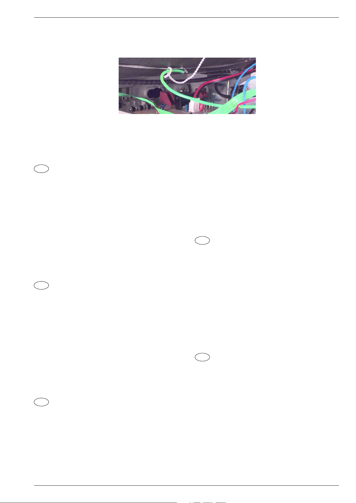
Masseleitung von Bildrohrplatte zum Masseband der Bildröhre:
Die Masseleitung ist am Masseband angeklemmt und verlötet. Muss
die Leitung gelöst werden, sollte diese unmittelbar an der Klemmstelle
abgetrennt werden. Beim Zusammenbau muss die Leitung nach dem
Anlöten mechanisch gesichert werden.
Defekte Bildröhre:
Im Defektfall der Bildröhre senden Sie Ihr Gerät an Ihre regionale
Kundendienststelle.
D
Service-Hinweise
Chassisausbau
Bevor Sie die Chassis-Verbindungsleitungen lösen, muss die Leitungsverlegung zu den einzelnen Baugruppen wie Netzschalterplatte, Bedieneinheit, Bildrohrplatte, Ablenkeinheit oder Lautsprecher beachtet werden.
Nach erfolgter Reparatur ist es notwendig, die Leitungsführung wieder
in den werkseitigen Zustand zu versetzen, um eventuell spätere
Ausfälle oder Störungen zu vermeiden.
Ground Wire from CRT Panel to the Ground Strap of the CRT:
The ground wire is clamped and soldered at the ground strap. To
remove the wire cut it directly beside the clamp. When reassembling
the wire must be secured mechanically after soldering.
Defective CRT:
In the event of a defective picture tube please send your TV set to your
local After-Sales Service.
Cable dereseau
Ces appareils ne peuvent être utilisés qu ' avec un cable de connecion
original de réseau avec bobine antiparasite intégré dans la fiche de
secteur. Ce câble de réseau empêche des perturbations de réseau et
est partie de l'autorisation d'appareil. Si nécessaire commandez
uniquement le cable de réseau selon la liste de pièces détachées.
Netzkabel
Diese Geräte dürfen nur mit dem Original-Netzanschlusskabel mit
integrierter Entstördrossel betrieben werden. Dieses Netzkabel verhindert Störungen aus dem Netz und ist Bestandteil der Gerätezulassung. Im Ersatzfall bestellen Sie bitte ausschließlich das Netzkabel laut Ersatzteilliste.
GB
Service Notes
Disassembly of the chassis
Before disconnecting the chassis connecting leads observe the way
they are routed to the individual assemblies like the mains switch
panel, keyboard control panel, picture tube panel, deflection unit or
loudspeaker.
On completion of the repairs the leads must be laid out as originally
fitted at the factory to avoid later failures or disturbances.
Mains cable
The TV receiver must only be operated with an original mains connecting
cable with an interference suppressor choke integrated in the mains
plug.This mains cable prevents interference from the mains supply and
is part of the product approval. For replacement please order exclusively
the mains connecting cable specified in the spare parts list.
F
Information pour la maintenance
Dèmontage de chassis
Avant de défaire les connecteurs du châssis princip, il y a lieu de
repérer auparavant les liaisons correspondant à chaque platine comme
par exemple le C.I. Inter secteur, le C.I. Commande, le C.I. Tube, le
bloc déviation ou les haut-parleurs.
A la fin de l'intervention, les connexions doivent être remises dans leur
position d'origine afin d'éviter par après d'éventuelles défaillances ou
perturbations.
I
Nota di servizio
Smontaggio del telaio
Prima di sfilare i cavi di collegamneto col telaio è necessario osservare
la disposizione originaria degli stessi verso le singole parti come la
piastra alimentazione, l'unità comandi, la piastra cinescopio, il giogo o
l'altoparlante.
Dopo la riparazione è necessario che gli ancoraggi e le guide
garantiscano la disposizione dei cavi analogamente a quella data in
fabrica e ciò per evitare disturbi o danni nel tempo.
Cavo rete
Gli apperechi devono essere messi in funzioni solo con il cavo originale
il colle gamento di rete e la sua spina di rete deve essere munita di una
bombina d´induttanza. In causa di sostituzione ordinate solo il cavo di
alimentatore che corrésponde alla lista degli accessori.
E
Nota de servicio
Desmontaje del chassis
Antes de desconectar las conecciones del Chassis hay que observar
la dirección de dichas conecciones a los distintos grupos de construcción
como la placa de conmutación de red, unidad de control, placa del
zócalo del tubo de imagen, unidad de deflección o altavoces.
Después de haber realizado la reparación y para evitar fallos o
pertubaciones posteriores es necesario reponer las conecciones tal
como fueron instaladas originalmente en fabrica.
Cable de red
El aparato solo se puede usar con el cable de red original con choque
antiparásito integrado en el enchufe de red. Este cable de red evita
perturbaciones de la red y es parte de la autorización del aparato. En
caso necesario puede pedir el cable de red según lista de piezas de
repuestos.
GRUNDIG Service 1 - 3
Page 4
1 - 4
Bildröhre / Picture Tube
Sichtbares Bild
Visible picture
Bildröhre
Picture tube
Elektronik / Electronic
Programmspeicherplätze
Programme positions
Tuner
TV-Normen
TV-Standards
Videotext
Teletext
Musikleistung
Music power
Anschlüsse Front / Connections Front
Kopfhörer
Headphones
Cinch-AV
Anschlüsse Rückwand / Connections Rear Panel
Euro AV 1 (schwarz/black)
Antenne
Antenna
Netzteil / Mains Stage
Netzspannung (Regelbereich)
Mains voltage (variable)
Netzfrequenz
Mains frequency
Leistungsaufnahme
Power consumption
GRUNDIG Service
Standby
DAVIO 37
P 37-2201
Chassis 12.5
34cm 34cm 34cm 48cm
37cm (14") Black Matrix,
Philips/90°
99 + 2 AV
PAL, via AV: NTSC 4.43MHz
RGB Eingang, Audio Eingang
Koaxial-Buchse DIN 45325
Coaxial socket acc. DIN 45325
B/G
-
Mono 5W Mono 5W
1 x FBAS Video/in
1 x CCVS Video/in
1 x Audio/in
(AV 2 Position)
FBAS Ein-/Ausgang,
CCVS in-/output,
RGB input, audio input
230V ±15%
50 / 60Hz
ca. 40W
ca. 4W
DAVIO 37
P 37-4201 TOP
Chassis 12.5
37cm (14") Black Matrix,
Philips/90°
99 + 2 AV
PLL Frequenz Synthesizer Tuning UHF/VHF, globale Pinbelegung
PLL frequency synthesizer tuning UHF/VHF, global pinning
PAL, via AV: NTSC 4.43MHz
RGB Eingang, Audio Eingang
Koaxial-Buchse DIN 45325
Coaxial socket acc. DIN 45325
B/G
7-Seiten-TOP/FLOF-Text
7-pages TOP/FLOF text
Mono 3,5mm Klinkenbuchse, schaltet internen Lautsprecher ab
Mono 3.5mm jack, aswitch off inserted speaker
1 x FBAS Video/in
1 x CCVS Video/in
1 x Audio/in
(AV 2 Position)
FBAS Ein-/Ausgang,
CCVS in-/output,
RGB input, audio input
230V ±15%
50 / 60Hz
ca. 40W
ca. 4W
DAVIO 37
P 37-4201/5 TOP
Chassis 12.5
37cm (14") Black Matrix,
Philips/90°
99 + 2 AV 99 + 2 AV
B/G, D/K/K'
PAL, SECAM,
via AV: NTSC 4.43MHz
7-Seiten-TOP/FLOF-Text
7-pages TOP/FLOF text
Mono 5W Mono 5W
1 x FBAS Video/in
1 x CCVS Video/in
1 x Audio/in
(AV 2 Position)
FBAS Ein-/Ausgang,
RGB Eingang, Audio Eingang
CCVS in-/output,
RGB input, audio input
Koaxial-Buchse DIN 45325
Coaxial socket acc. DIN 45325
230V ±15%
50 / 60Hz
ca. 40W
ca. 4W
DAVIO 51
T 51-4201 TOP
Chassis 12.5
51cm (20") Black Matrix,
Thomson/90°, (Samsung)
PAL, via AV: NTSC 4.43MHz
RGB Eingang, Audio Eingang
Koaxial-Buchse DIN 45325
Coaxial socket acc. DIN 45325
B/G
7-Seiten-TOP/FLOF-Text
7-pages TOP/FLOF text
1 x FBAS Video/in
1 x CCVS Video/in
1 x Audio/in
(AV 2 Position)
FBAS Ein-/Ausgang,
CCVS in-/output,
RGB input, audio input
230V ±15%
50 / 60Hz
ca. 50W
ca. 4W
Allgemeiner Teil / General Section
Technische Daten / Technical Data
Chassis 12.5
Page 5
GRUNDIG Service 1 - 5
Bildröhre / Picture Tube
Sichtbares Bild
Visible picture
Bildröhre
Picture tube
Elektronik / Electronic
Programmspeicherplätze
Programme positions
Tuner
TV-Normen
TV-Standards
Videotext
Teletext
Musikleistung
Music power
Anschlüsse Front / Connections Front
Kopfhörer
Headphones
Cinch-AV
Anschlüsse Rückwand / Connections Rear Panel
Euro AV 1 (schwarz/black)
Antenne
Antenna
Netzteil / Mains Stage
Netzspannung (Regelbereich)
Mains voltage (variable)
Netzfrequenz
Mains frequency
Leistungsaufnahme
Power consumption
Standby
DAVIO 51
T 51-4201/5 TOP
Chassis 12.5
48cm 51cm 51cm
51cm (20") Black Matrix,
Thomson/90°, (Samsung)
99 + 2 AV
PLL Frequenz Synthesizer Tuning UHF/VHF, globale Pinbelegung
PLL frequency synthesizer tuning UHF/VHF, global pinning
B/G, D/K/K'
PAL, SECAM,
via AV: NTSC 4.43MHz
7-Seiten-TOP/FLOF-Text
7-pages TOP/FLOF text
Mono 5W Mono 5W
Mono 3,5mm Klinkenbuchse, schaltet internen Lautsprecher ab
Mono 3.5mm jack, aswitch off inserted speaker
1 x FBAS Video/in
1 x CCVS Video/in
1 x Audio/in
(AV 2 Position)
FBAS Ein-/Ausgang,
RGB Eingang, Audio Eingang
CCVS in-/output,
RGB input, audio input
Koaxial-Buchse DIN 45325
Coaxial socket acc. DIN 45325
230V ±15%
50 / 60Hz
ca. 50W
ca. 4W
DAVIO 55
T 55-4201 TOP
Chassis 12.5
55cm (21"), FST, Black Matrix,
Philips/90°, (Thomson/Samsung)
99 + 2 AV
PAL, via AV: NTSC 4.43MHz
RGB Eingang, Audio Eingang
Koaxial-Buchse DIN 45325
Coaxial socket acc. DIN 45325
B/G
7-Seiten-TOP/FLOF-Text
7-pages TOP/FLOF text
1 x FBAS Video/in
1 x CCVS Video/in
1 x Audio/in
(AV 2 Position)
FBAS Ein-/Ausgang,
CCVS in-/output,
RGB input, audio input
230V ±15%
50 / 60Hz
ca. 50W
ca. 4W
DAVIO 55
T 55-4201/5 TOP
Chassis 12.5
55cm (21"), FST, Black Matrix,
Philips/90°, (Thomson/Samsung)
99 + 2 AV
B/G, D/K/K'
PAL, SECAM,
via AV: NTSC 4.43MHz
7-Seiten-TOP/FLOF-Text
7-pages TOP/FLOF text
Mono 5W
1 x FBAS Video/in
1 x CCVS Video/in
1 x Audio/in
(AV 2 Position)
FBAS Ein-/Ausgang,
RGB Eingang, Audio Eingang
CCVS in-/output,
RGB input, audio input
Koaxial-Buchse DIN 45325
Coaxial socket acc. DIN 45325
230V ±15%
50 / 60Hz
ca. 50W
ca. 4W
sten vorgeschriebenen Typen verwendet werden.
the spare parts lists.
Schutzschaltungen im Gerät dürfen nur kurzzeitig außer Betrieb
Beim Austausch der Bildröhre dürfen nur die in den Ersatzteilli-
flection stage it is imperative that the EHT for the picture tube is
checked and re-adjusted if necessary.
tube the integrated protective circuits are allowed to be put out
of operation only for a short time.
To avoid consequential damages to the chassis or the picture
When replacing the picture tube use only the types specified in
Die Hochspannung für die Bildröhre und die damit auftretende
Nach jeder Reparatur im Netzteil oder in der Horizontalablen-
on Regulations (January 8, 1987), issued by the Physikalisch-
Technische Bundesanstalt (federal physiotechnical institution).
radiation depends on the precise adjustment of the +B power
supply.
The high tension for the picture tube and thus the developing X-
After every repair of the power supply unit or the horizontal de-
Sicherheits-Hinweise
Die in den Fernsehgeräten auftretende Röntgenstrahlung ent-
Safety Advices
The X-radiation developing in the sets conforms to the X-radiati-
spricht den Bestimmungen der Physikalisch-Technischen Bun-
desanstalt vom 8. Januar 1987.
Röntgenstrahlung ist abhängig von der exakten Einstellung der
Netzteilspannung +B.
kung ist die Hochspannung zu messen und gegebenenfalls ein-
zustellen.
gesetzt werden, um Folgeschäden am Chassis oder an der
Bildröhre zu vermeiden.
Allgemeiner Teil / General SectionChassis 12.5
Page 6
1 - 6
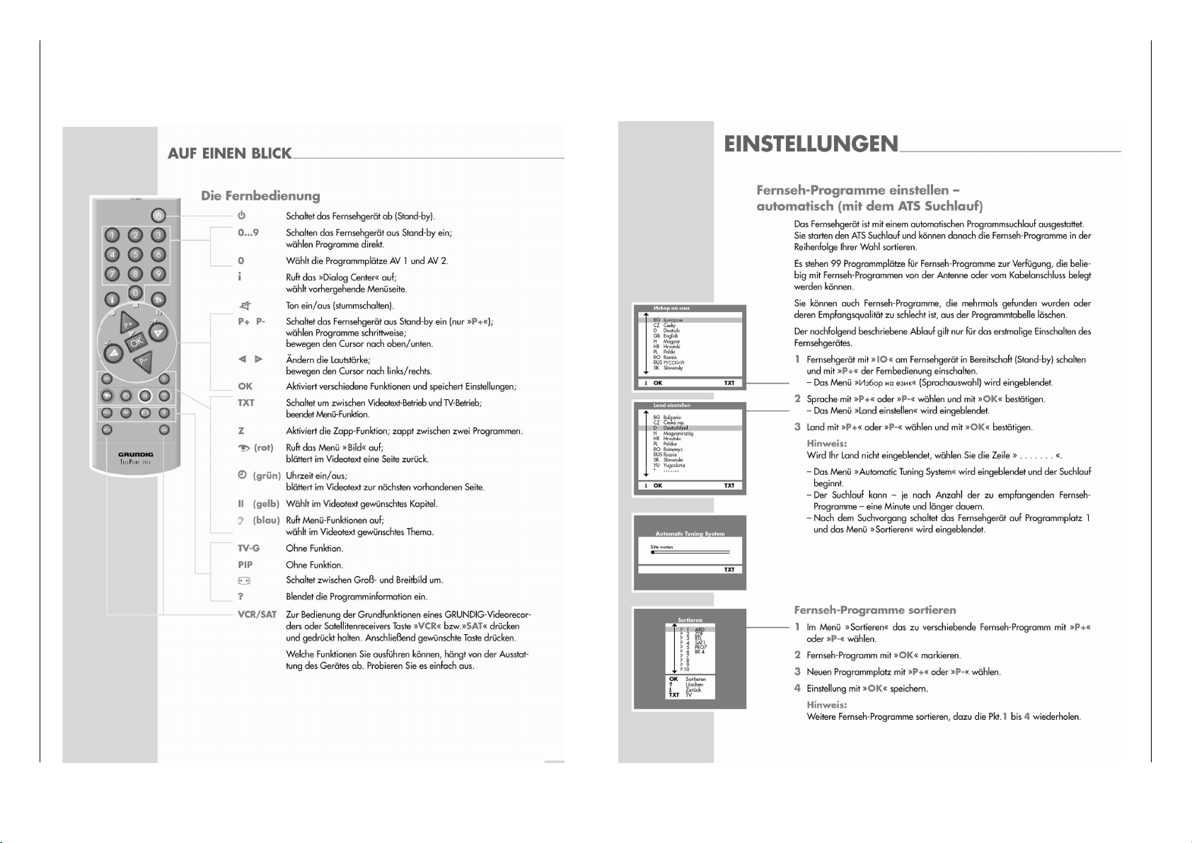
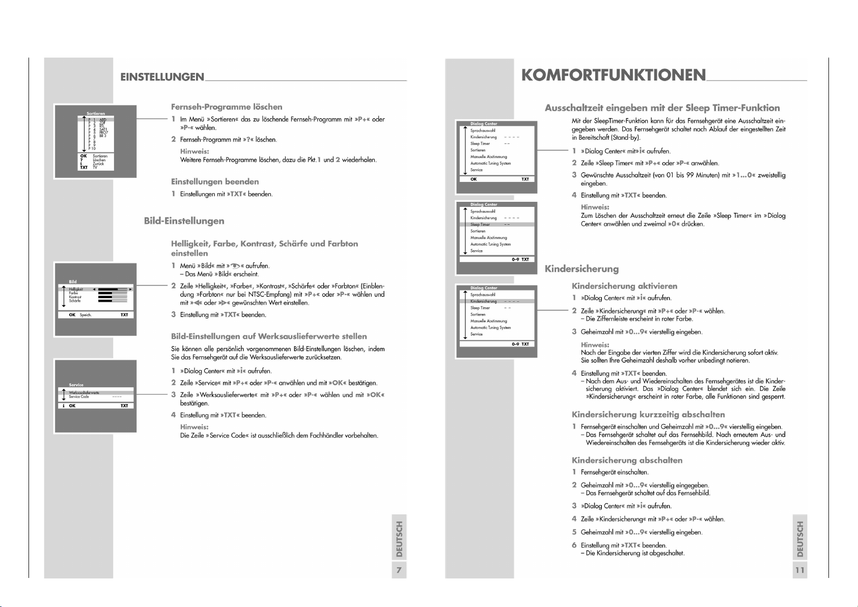
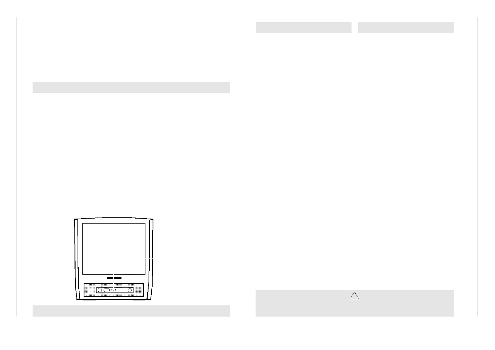
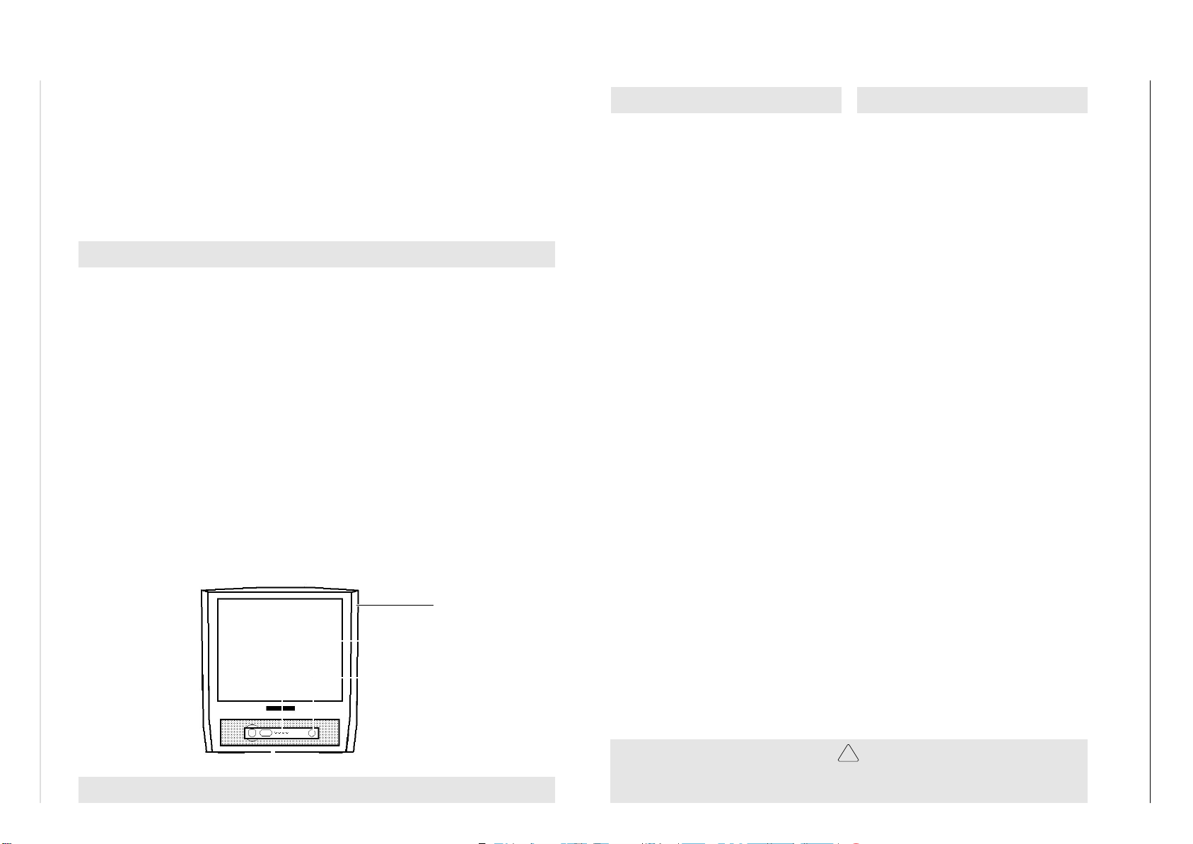
Bedienhinweise Dieses Kapitel enthält Auszüge aus der Bedienungsanleitung.
Weitergehende Informationen entnehmen Sie bitte der gerätespezifischen Bedienungsanleitung, deren Materialnummer Sie in der entsprechenden Ersatzteilliste finden.
Allgemeiner Teil / General Section
GRUNDIG Service
Chassis 12.5
Page 7
GRUNDIG Service 1 - 7
Allgemeiner Teil / General SectionChassis 12.5
Page 8
1 - 8
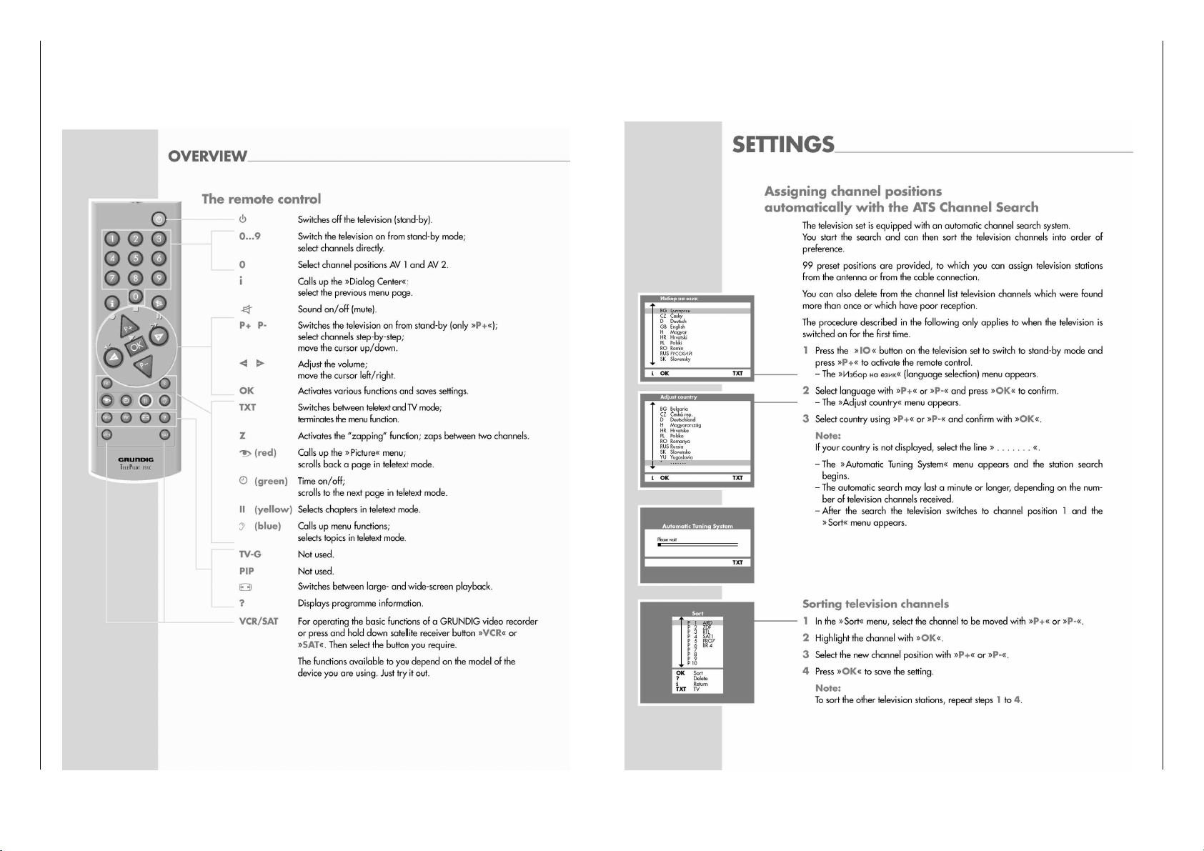
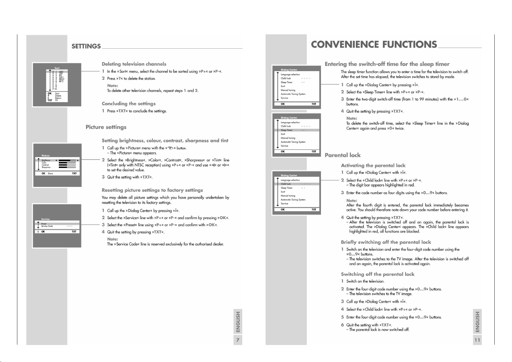
Operating Hints This chapter contains excerpts from the operating instructions.
For further particulars please refer to the appropriate user instructions the part number of which is indicated in the relevant spare parts list.
Allgemeiner Teil / General Section
GRUNDIG Service
Chassis 12.5
Page 9
GRUNDIG Service 1 - 9
Allgemeiner Teil / General SectionChassis 12.5
Page 10

1 - 10
Gerät / Type of Set
"OK" –> Service Code "8500". Die Menüs 1 bis 4 werden über die
Mode. Alle mit * und ** gekennzeichneten Werte müssen zusätzlich
nach Abgleich (Seite 2 - 1) abgeglichen werden.
Nachfolgende Tabelle zeigt alle Grundeinstellungen im Service
Tasten "Rot", "Grün", "Gelb" und "Blau" aufgerufen.
Service Mode aktivieren: Tast er "Ǻ" (Dialog Center) –> Service –>
Service Mode beenden: Taste "TXT" drücken.
1. Grundeinstellwerte
Allgemeiner Teil / General Section
Service- und Sonderfunktionen
GRUNDIG Service
Menü
Menu
Menü 1 / Menu 1
(Taste "Rot" / button "red")
Menüpunkt
Point of Menu
Ƕ oder/or ǵ
Tuner
AGC
ST.BY
AV2
HOTEL
H.VOL
VERS.
TEXT
OEM
VIDEO
Einstellung
Adjustment
Ǹ oder/or Ƿ
SHARP&ALPS
PHILIPS
P.SONIC
TEMIC
siehe Abgleich / see adjustment
YES
NO
YES
NO
YES
NO
Zahlenwert/Value
WEST
EAST
FRANCE
MIDDLE EAST
NON TEXT
DEFAULT
FASTTEXT
TOPTEXT
TOPTEXT+FASTTEXT
OFF
A
B
siehe Abgleich / see adjustment
Hinweis
Hint
DAVIO 37 P37-2201
Tunerversion / version of tuner
Tunerversion / version of tuner
Tunerversion / version of tuner
Tunerversion / version of tuner
Automatik-Standby >10min. ohne Signal / automatic standby >5 min. without signal
Automatik-Standby "aus" / automatic standby "off"
AV2-Buchse an Frontseite /AV2 socket at front side
Nur AV1-Buchse an Rückseite / only AV1 socket at rear side
Hotel Mode "ein" / hotel mode "on"
Hotel Mode "aus" / hotel mode "off"
Maximale Lautstärke wenn HOTEL = YES / maximum volume when HOTEL = YES
PAL B/G
PAL/SECAM B/G, D/K
PAL/SECAM/NTSC4.43 B/G, I, L/L'
PAL/SECAM/NTSC4.43+3.58 B/G, I, D/K, M'
Kein Videotext / no teletext
Videotext / teletext
Fasttext / fasttext
Toptext / toptext
Toptext+Fasttext / toptext+fasttext
OSD-Farben Blau/Weiß / OSD colours blue/white
OSD-Farben Rot/Weiß / OSD colours red/white
OSD-Farben Blau/Cyan / OSD colours blue/cyan
x
19*
x
x
x
x
x
x
DAVIO 37 P37-4201 TOP
DAVIO 37 P37-4201/5 TOP
xx
19* 19*
xx
xx
xx
x
x
xx
xx
DAVIO 51 P51-4201 TOP
DAVIO 51 P51-4201/5 TOP
DAVIO 55 P55-4201 TOP
DAVIO 55 P55-4201/5 TOP
xx
19* 19*
xx
xx
xxxxx
xxxx
xxxx
xx
19* 19*
xx
xx
x
xx
"OK" –> Service Code "8500". Activate menus 1 to 4 via buttons
addition all values marked with * and ** must be adjusted according
to adjustment (page 2 - 3).
The following table shows all basic settings in the service mode. In
"red", "green", "yellow" and "blue".
End the Service Mode: Press button "TXT".
1. Basic Settings
Service and Special Funktions
Start of the Service Mode: Via "Ǻ" (Dialog Center) –> Service –>
* Mittelwert / Average Value
** Mittelwert, bei Philips Bildröhren 20"/21" Einstellwert "20" / Average Value, for Philips 20"/21" CRTs Adjust to value "20"
Chassis 12.5
Page 11

GRUNDIG Service 1 - 11
Gerät / Type of Set
Menü
Menu
"green")
Menü 2 / Menu 2
(Taste "Grün" / button
"yellow")
Menü 3 / Menu 3
(Taste "Gelb" / button
Menüpunkt
Point of Menu
Ƕ oder/or ǵ
H.POS
V.POS
V.HE I
LNRTY
S-COR
Y. D LY
OSD.H
OSD.V
R.CUT
G.CUT
B.CUT
R.DRV
B.DRV
SCRN
SECBL
AFT38
Einstellung
Adjustment
Ǹ oder/or Ƿ
siehe Abgleich / see adjustment
siehe Abgleich / see adjustment
siehe Abgleich / see adjustment
siehe Abgleich / see adjustment
siehe Abgleich / see adjustment
siehe Abgleich / see adjustment
siehe Abgleich / see adjustment
siehe Abgleich / see adjustment
siehe Abgleich / see adjustment
siehe Abgleich / see adjustment
siehe Abgleich / see adjustment
siehe Abgleich / see adjustment
siehe Abgleich / see adjustment
siehe Abgleich / see adjustment
Hinweis
Hint
Horizontale Bildlage / horizontal position
Vertikale Bildlage / vertical position
Vertikale Größe / vertical size
Vertikale Linearität / vertical linearity
S-Korrektur / S correktion
OSD Position horizontal / horizontal OSD position
OSD Position vertikal / vertical OSD position
Cut off-Wert "rot" / Cut off value "red"
Cut off-Wert "grün" / Cut off value "green"
Cut off-Wert "blau" / Cut off value "blue"
Weißabgleich "Rotwert" /white balance "red" value
Weißabgleich "Blauwert" / white balance "blue" value
Abgleich Schirmgitterspannung / screen grid voltage adjustment
AFC-Abgleich 38,9MHz / AFC adjustment 38.9MHz
DAVIO 37 P37-2201
DAVIO 37 P37-4201 TOP
14*
14*4*14*
4*
64*
64*
46*
46*
0*
0*00*
0
25*
25*
33*
33*
127**
127**
128**
128**
124**
124**
59*
59*
53*
53* 53*
48*
48*
40*
40*
4*
64*
46*
0
25*
33*
127**
128**
124**
59*
48*
40*
DAVIO 37 P37-4201/5 TOP
128**
128**
119**
DAVIO 51 P51-4201 TOP
13*4*13*
4*
80*
80*
47*
47*
0*00*
0
25*
25*
33*
33*
128**
128**
119**
58*
58*
59* 59*
48*
48*
40*
40*
DAVIO 51 P51-4201/5 TOP
126**
128**
121**
DAVIO 55 P55-4201 TOP
14*4*14*
4*
81*
81*
47*
47*
0*00*
0
25*
25*
33*
33*
126**
128**
121**
55*
55*
56* 56*
48*
48*
40*
40*
DAVIO 55 P55-4201/5 TOP
(Taste
Menu 4
Menü 4 /
* Mittelwert / Average Value
** Mittelwert, bei Philips Bildröhren 20"/21" Einstellwert "20" / Average Value, for Philips 20"/21" CRTs Adjust to value "20"
ton "blue")
"Blau" / but-
AFT33
siehe Abgleich / see adjustment
AFC-Abgleich 33,9MHz / AFC adjustment 33.9MHz
61* 61* 61*
61* 61* 61* 61*
Allgemeiner Teil / General SectionChassis 12.5
Page 12

Allgemeiner Teil / General Section
Chassis 12.5
2. Austausch des Speicher-IC402
Nach Austausch von IC402 müssen alle Einstellungen im Service
Mode nach Tabelle "Grundeinstellwerte" (Punkt 1) eingestellt werden.
3. Hotel Mode
3.1 Hotel Mode aktivieren
Der Hotel Mode wird im Service Mode (Menü 1) eingestellt.
Menüpunkt "Hotel" mit Taste
Ƕ oder ǵ anwählen, mit Taste
Ǹ oder Ƿ "YES" einstellen. Service Mode verlassen.
Bei aktiviertem Hotel Mode ist:
- Im "Dialog Center" nur noch der "SLEEP TIMER" anwählbar.
- Die zuletzt eingestellte Lautstärke die maximale Lautstärke die
gespeichert wird (H.VOL im Menü 1 des Service Modes).
3.2 Hotel Mode deaktivieren
ǺǺ
ǺǺ
" der Fernbedienung gedückt halten und Gerät mit dem
Taste "
Netzschalter einschalten. Menüpunkt "Hotel" im Menü 1 des Ser-
vice Modes mit Taste Ƕ oder ǵ anwählen, mit Taste Ǹ oder Ƿ
"NO" einstellen.
4. Programmsperre (Kindersicherung) dauerhaft aufheben
Die Zahl "7038" hebt die Sperre dauerhaft auf.
5. ATS-Reset (Automatic Tuning System)
Netzschalter "EIN" mit gedrückter Fernbedientaste "L+" –> Sprachauswahl –> Länderauswahl -> "OK".
Das Automatische Sendersuchsystem stoppt bei jedem empfangswürdigen Sender (AFC und Koinzidenz) und speichert automatisch
die entsprechenden Senderdaten mit dem jeweiligen Standard. Danach wird der Suchlauf fortgesetzt.
Tastendruck "TXT" bricht den ATS-Lauf ab. Wird ATS abgebrochen
bevor ein Sender gefunden wurde, startet ATS wieder automatisch
nach dem Einschalten.
6. Software-Versionsnummer
Die Software-Versionsnummer wird nach Beenden des Service Modes angezeigt.
2. Change of the Memory IC402
After changing IC402 all settings in the service mode must be done
according to the table "Basic Settings" (point 1).
3. Hotel Mode
3.1 Activating the Hotel Mode
The Hotel Mode can be activated via Service Mode (menu 1).
Select point of menu "Hotel" with button
Ƕ or ǵ, with button
Ǹ or Ƿ set to "YES". End the Service Mode.
With activated Hotel Mode:
- only the "SLEEP TIMER" can be selected in the "Dialog Center".
- the last volume setting is stored as the maximum level possible
(H.VOL in menu 1 of the Service Mode).
3.2 Deactivating the Hotel Mode
ǺǺ
ǺǺ
Press and hold button "
ching the TV set on with the mains switch. Select point of menu
"Hotel" in menu 1 of Service Mode via button Ƕ or ǵ, set with button Ǹ or Ƿ to "NO".
4. Cancelling the Parental Lock Continuously
To cancel the parental lock enter the number "7038".
5. ATS Reset (Automatic Tuning System)
Press the power "ON" button while pressing button "L+" on the Remote Control –> Language Selection –> Country Selection -> "OK".
The ATS system stops at every station of acceptable reception quality (AFC and coincidence) and stores the station data and the respective standard automatically. The system then continues searching.
Pressing the "TXT" button stops the ATS function. If ATS will be
stopped before storing anyone station, ATS will start again when
switching on the TV again.
6. Software Version Number
The software version number is shown after ending the service
mode.
" on the remote control handset while swit-
1 - 12
GRUNDIG Service
Page 13

Chassis 12.5 Abgleich / Alignment
D
Abgleich
Service Mode aktivieren: Über "Ǻ" (Dialog Center) –> Service –> "OK" –> Service Code "8500".
Service Mode deaktivieren: Taste "TXT" drücken.
Messgeräte: 100MHz-Oszilloskop mit Tastkopf 10:1, Digitalvoltmeter, Farbbildgenerator.
Servicearbeiten nach Austausch bzw. Reparatur:
- Netzteil: Abgleich 1
- ZF: Abgleich 2
- IC101 (Video-IC), EEPROM: Abgleich 2
- Bildröhre, Bildrohrplatte: Abgleich 6…8
- Ablenkung: Abgleich 7
- IC402: Abgleich 2…5 und 7…8
Abgleich Vorbereitung Abgleichvorgang
1. +B Spannung
2. ZF
Normen B/G, D/K, I
Norm SECAM L/L'
3. Tuner-AGC
Nach jeder Reparatur und vor jedem Abgleich kontrollieren
und gegebenenfalls einstellen.
Helligkeit: Minimum
Kontrast: Minimum
Digitalvoltmeter: Kathode D610
Service Mode aktivieren; Menü 1 anwählen ("rote" Taste).
Mit Taste Ƕ "Video" auswählen.
Normsender einspeisen. Feintuning auf "00" stellen.
Mit OK speichern.
Service Mode aktivieren; Menü 4 anwählen ("blaue" Taste).
Mit Taste Ƕoder ǵ "AFT38" auswählen.
Normsender einspeisen. Feintuning auf "00" stellen.
Mit OK speichern.
Service Mode aktivieren; Menü 4 anwählen ("blaue" Taste).
Mit Taste Ƕoder ǵ "AFT33" auswählen.
100MHz-Oszilloskop: Kanal A: Tuner Kontakt 11
Masse: Tuner
Farbbildgenerator: Farbtreppe (mit abgeschaltetem
Tonträger) über die Antenne einspeisen: Kanal 32; 70±1dBµV.
Service Mode aktivieren; Menü 1 anwählen ("rote" Taste).
Mit Taste Ƕoder ǵ "AGC" auswählen.
+B mit P601 auf folgende Werte einstellen:
Größe Bildröhre Spannungswert
14" A34EAC01X06 105V
20" A48EJW011X21 116V
20" A48ECR43X51 118V
20" A48EKB01X01 119V
21" A51EER33X41 118V
21" A51EFS83X191 110V
21" A51EAL155X01 115V
21" A51EAL135X01 115V
21" A51EAL135X02 115V
21" A51QAE320X67 118V
21" A51EKE01X01 115V
Mit Taste Ƿ auf "NEW" stellen; Service Mode deaktivieren.
Mit Taste Ǹ oder Ƿ rechten Hex-Wert auf 78-7C einstellen
(Beispiel: AFT38 87 79).
Service Mode deaktivieren.
Mit Taste Ǹ oder Ƿ rechten Hex-Wert auf 78-7C einstellen
(Beispiel: AFT33 87 79).
Service Mode deaktivieren.
Mit Taste Ǹ oder Ƿ folgende Messwerte einstellen:
Norm PAL B/G .................................... 820mV
Normen PAL/SECAM B/G/D/K ........... 820mV
Norm SECAM L/L' .............................. 450mV
Norm PAL I ......................................... 500mV
±20mV
ss
±20mV
ss
±20mV
ss
±20mV
ss
Service Mode deaktivieren.
ss
ss
ss
ss
4. OSD
5. OEM
6. Schirmgitterspannung
Service Mode aktivieren; Menü 2 anwählen ("grüne" Taste).
Mit Taste Ƕoder ǵ "OSD.H" und "OSD.V" auswählen.
Service Mode aktivieren; Menü 1 anwählen ("rote Taste").
Mit Taste Ƕoder ǵ "OEM" auswählen.
Service Mode aktivieren; Menü 3 anwählen ("gelbe" Taste).
Mit Taste Ƕoder ǵ "SCRN" auswählen.
Mit Taste Ǹ oder Ƿ Bild auf Bildschirm-Mitte stellen;
Service Mode deaktivieren.
Mit Taste Ǹ oder Ƿ auf "off" stellen;
Service Mode deaktivieren.
Mit Regler "SCREEN" (unterer Regler am Zeilentrafo) den
Strich am Bildschirm gerade gut sichtbar einstellen.
Mit Taste Ǹ oder Ƿ horizontalen Strich einschalten.
GRUNDIG Service 2 - 1
Page 14

Abgleich / Alignment Chassis 12.5
Abgleich Vorbereitung Abgleichvorgang
7. Geometrie
7.1 Horizontale
Bild-Position
7.2 Vertikale
Bild-Position
7.3 Bild-Höhe
7.4 Vertikale
Bild-Linearität
7.5 S-Korrektur
8. Weißabgleich
8.1 für Geräte mit
21" oder 22"
Philipsbildröhre
Geometrie-Testbild einspeisen
Service Mode aktivieren; Menü 2 anwählen ("grüne" Taste).
Mit Taste Ƕoder ǵ "H.POS" auswählen.
Mit Taste Ƕoder ǵ "V.POS" auswählen.
Mit Taste Ƕoder ǵ "V.HEI" auswählen.
Mit Taste Ƕoder ǵ "LNRTY" auswählen.
Mit Taste Ƕoder ǵ "S.COR" auswählen.
Farbbildgenerator: Grautreppe mit Burst einspeisen.
Kontrast: Maximum
Farbkontrast: Mittelwert
Bildschirmhelligkeit: Mittelwert
Service Mode aktivieren; Menü 3 anwählen ("gelbe" Taste).
Mit Taste Ƕoder ǵ "G.CUT" auswählen.
Mit Taste Ƕoder ǵ "R.CUT" auswählen.
Mit Taste Ƕoder ǵ "B.CUT" auswählen.
Mit Taste Ƕoder ǵ "R.DRV" auswählen.
Mit Taste Ƕoder ǵ "B.DRV" auswählen.
Mit Taste Ǹ oder Ƿ nach Testbild einstellen.
Mit Taste Ǹ oder Ƿ nach Testbild einstellen.
Mit Taste Ǹ oder Ƿ nach Testbild einstellen.
Mit Taste Ǹ oder Ƿ nach Testbild einstellen.
Mit Taste Ǹ oder Ƿ nach Testbild einstellen.
Mit Taste Ǹ oder Ƿ "20" einstellen.
Mit Taste Ǹ oder Ƿ "20" einstellen.
Mit Taste Ǹ oder Ƿ "20" einstellen.
Mit Taste Ǹ oder Ƿ weißen Bildbereich auf unbunt einstel-
len. Läßt sich der Weißwert nicht einstellen, Wert für
"G.CUT" korrigieren.
8.2 für alle anderen
Geräte
Mit Taste Ƕoder ǵ "G.CUT" auswählen.
Mit Taste Ƕoder ǵ "R.CUT" auswählen.
Mit Taste Ƕoder ǵ "B.CUT" auswählen.
Mit Taste Ƕoder ǵ "R.DRV" auswählen.
Mit Taste Ƕoder ǵ "B.DRV" auswählen.
Mit Taste Ǹ oder Ƿ "128" einstellen.
Mit Taste Ǹ oder Ƿ "128" einstellen.
Mit Taste Ǹ oder Ƿ "121" einstellen.
schwarzer Bildbereich sollte unbunt sein.
Bei Bedarf Werte für "R.CUT" und "B.CUT" korrigieren.
Mit Taste Ǹ oder Ƿ weißen Bildbereich auf unbunt einstel-
len. Läßt sich der Weißwert nicht einstellen, Wert für
"G.CUT" korrigieren.
2 - 2 GRUNDIG Service
Page 15

Chassis 12.5 Abgleich / Alignment
GB
Alignment
Start of the Service Mode: Via "Ǻ" (Dialog Center) –> Service –> "OK" –> Service Code "8500".
End the Service Mode: Press button "TXT".
Measuring instruments: 100MHz oscilloscop with 10:1 test probe, digital voltmeter, colour video generator.
Service works after replacement or repair of the following modules:
- Power supply: alignment 1
- IF: alignment 2
- IC101 (Video IC), EEPROM: alignment 2
- CRT, CRT panel: alignment 6…8
- Deflection: alignment 7
- IC402: alignment 2…5 and 7…8
Alignment Preparations Alignment Process
1. +B voltage
2. IF
B/G,D/K,I Standard
SECAM LL'
Standard
3. Tuner AGC
This voltage must be checked and re-adjusted if necessary
after every repair and before every alignment.
Brightness: Minimum
Contrast: Minimum
Digital voltmeter: Cathode D610
Start the Service Mode; call up the dialog line "Video" via
menu 1 (red button) with button Ƕ.
Feed in a standard signal of a TV station. Set fine tuning to
"00" and store it via "OK".
Start the Service Mode; call up the dialog line "AFT38" via
menu 4 (blue button) with button Ƕor ǵ.
Feed in a standard signal of a TV station. Set fine tuning to
"00" and store it via "OK".
Start the Service Mode; call up the dialog line "AFT33" via
menu 4 (blue button) with button Ƕor ǵ.
100MHz oscilloscope: Channel A: Tuner contact 11
Ground: Tuner
Colour video generator: Feed in a colour scale (with
switched-off sound carrier) via the
aerial: channel 32; 70±1dBµV.
Start the Service Mode; call up the dialog line "AGC" via
menu 1 (red button) with button Ƕor ǵ.
Adjust +B to the values below with P601:
Size CRT Voltage Value
14" A34EAC01X06 105V
20" A48EJW011X21 116V
20" A48ECR43X51 118V
20" A48EKB01X01 119V
21" A51EER33X41 118V
21" A51EFS83X191 110V
21" A51EAL155X01 115V
21" A51EAL135X01 115V
21" A51EAL135X02 115V
21" A51QAE320X67 118V
21" A51EKE01X01 115V
With button Ƿ set to "NEW".
End the Service Mode.
With button Ǹ or Ƿ set the right Hex-value to 78-7C
(e.g.: AFT38 87 79).
End the Service Mode.
With button Ǹ or Ƿ set the right Hex-value to 78-7C
(e.g.: AFT33 87 79).
End the Service Mode.
With button Ǹ or Ƿ set to the following values:
PAL B/G standard............................... 820mV
PAL/SECAM B/G/D/K standard ......... 820mV
SECAM L/L' standard ......................... 450mV
PAL I standard ....................................500mV
±20mV
pp
±20mV
pp
±20mV
pp
±20mV
pp
End the Service Mode.
pp
pp
pp
pp
4. OSD
5. OEM
6. Screen grid
voltage
Start the Service Mode; call up the dialog line "OSD.H" and
"OSD.V" via menu 2 (green button) with button Ƕor ǵ.
Start the Service Mode; call up the dialog line "OEM" via
menu 1 (red button) with button Ƕor ǵ.
Start the Service Mode; call up the dialog line "SCRN" via
menu 3 (yellow button) with button Ƕor ǵ.
With button Ǹ or Ƿ position the picture to the center of the
screen. End the Service Mode.
With button Ǹ or Ƿ set to "off".
End the Service Mode.
With "SCREEN" control (lower control at the splitter
transformer) adjust the line so that it is just well visible.
Switch on the horizontal line with button Ǹ or Ƿ.
GRUNDIG Service 2 - 3
Page 16

Abgleich / Alignment Chassis 12.5
Alignment Preparations Alignment Process
7. Geometry
7.1 Horizontal
position
7.2 Vertical
position
7.3 Vertical size
7.4 Vertical
linearity
7.5 S-correction
8. White balance
8.1 For sets with
21" or 22"
Philips CRT
Feed in a geometry test pattern.
Start the Service Mode; call up menu 2 (green button).
Select "H.POS" with button Ƕor ǵ.
Select "V.POS" with button Ƕor ǵ.
Select "V.HEI" with button Ƕor ǵ.
Select "LNRTY" with button Ƕor ǵ.
Select "S.COR" with button Ƕor ǵ.
Colour video generator: Feed in a grey scale with burst.
Contrast: maximum
Colour contrast: mid-position
Screen brightness: mid-position
Start the Service Mode; call up menu 3 (yellow button).
Select "G.CUT" with button Ƕor ǵ.
Select "R.CUT" with button Ƕor ǵ.
Select "B.CUT" with button Ƕor ǵ.
Select "R.DRV" with button Ƕor ǵ.
Select "B.DRV" with button Ƕor ǵ.
Adjust according to the test pattern using button Ǹ oder Ƿ .
Adjust according to the test pattern using button Ǹ oder Ƿ .
Adjust according to the test pattern using button Ǹ oder Ƿ .
Adjust according to the test pattern using button Ǹ oder Ƿ .
Adjust according to the test pattern using button Ǹ oder Ƿ .
With button Ǹ or Ƿ set the value to "20".
With button Ǹ or Ƿ set the value to "20".
With button Ǹ or Ƿ set the value to "20".
With button Ǹ or Ƿ set the values so that white part of the
picture becomes achromatic. Change the "G.CUT" value a
few unit if white balance could not be adjusted.
8.2 For all other sets
Select "G.CUT" with button Ƕor ǵ.
Select "R.CUT" with button Ƕor ǵ.
Select "B.CUT" with button Ƕor ǵ.
Select "R.DRV" with button Ƕor ǵ.
Select "B.DRV" with button Ƕor ǵ.
With button Ǹ or Ƿ set the value to "128".
With button Ǹ or Ƿ set the value to "128".
With button Ǹ or Ƿ set the value to "121".
the black part of the picture should be achromatic.
If not change the values for "R.CUT" and "B.CUT".
With button Ǹ or Ƿ set the values so that white part of the
picture becomes achromatic. Change the "G.CUT" value a
few unit if white balance could not be adjusted.
2 - 4 GRUNDIG Service
Page 17

Chassis 12.5 Platinenabbildungen und Schaltpläne / Layout of PCBs and Circuit Diagrams
OPTION - TELETEXT
table
8
7
6
Platinenabbildungen und Schaltpläne / Layout of PCBs and Circuit Diagrams
Netzteil / Mains Section
Chassis 12.5 Platinenabbildungen und Schaltpläne / Layout of PCBs and Circuit Diagrams
5
9R/2 pin
2x27mH E type
1
3,0V
TV on
TO WEB SUPPLY KABLO 3
OPTION - VS
3
4
Die +B-Spannung ist abhängig von der
eingebauten Bildröhre (Abgleich S.2-1)
The +B voltage depends on the type of
CRT (Adjustment P. 2-3)
Size Type of CRT +B
14" A34EAC01X06 105V
20" A48EJW011X21 116V
20" A48ECR43X51 118V
20" A48EKB01X01 119V
21" A51EER33X41 118V
21" A51EFS83X191 110V
21" A51EAL155X01 115V
21" A51EAL135X01 115V
21" A51EAL135X02 115V
21" A51QAE320X67 118V
21" A51EKE01X01 115V
2
Kennzeichen für Chip-Bauteil
Mark of chip components
Horizontal-Ablenkung / Horizontal Deflection
10
9
11
12
13
table
14
table table
C518
6,8n
14˝
20˝
9,1n
7,5n
21˝
C526
-
-
330p
R133
4,7R
2,2R
2,2R
15
17
16
R504
470R
470R
220R
table
table
R532
18k
12k
12k
R533
4,7R
short
short
Vertikal-Ablenkung / Vertical Deflection
R530
0,68R 0,5W
0,47R 0,5W
0,68R 0,5W
GRUNDIG Service
3 - 1
GRUNDIG Service
3 - 2
Page 18

Platinenabbildungen und Schaltpläne / Layout of PCBs and Circuit Diagrams Chassis 12.5
Chassisplatte / Chassis Board
4632
Bestückungsseite, Ansicht von oben
Component Side, Top View
45 44 31
Platinenabbildungen und Schaltpläne / Layout of PCBs and Circuit Diagrams Chassis 12.5
42
37
30
35
36
39
40
41
38
43
17
10
21
22
19
20
18
23
24
29
28
27
7
26
9
6
8
11
12
15
16
14
13
5 1 4 3 2
3 - 3
GRUNDIG Service
3 - 4
GRUNDIG Service
Page 19

Chassis 12.5 Platinenabbildungen und Schaltpläne / Layout of the PCBs and Circuit Diagrams
Oszillogramme Chassisplatte / Oscillograms Chassis Board
2
1
4
TV ein/on
4
TV ein/on
Standby
2
5
Standby
3
8
7 8
9 ßI
ß? ß` ßQ ßW
ßE ßR ßT ßZ
ßU ´? ´` ´Q
GRUNDIG Service 3 - 5
Page 20

Platinenabbildungen und Schaltpläne / Layout of the PCBs and Circuit Diagrams Chassis 12.5
´W ´R ´T ´Z
´U qI q? q`
qE qR
qT
qZ
qU wI w? w`
wQ
wW wE wR
3 - 6 GRUNDIG Service
Page 21

Chassis 12.5 Platinenabbildungen und Schaltpläne / Layout of PCBs and Circuit Diagrams
Chassisplatte / Chassis Board
Chassis 12.5 Platinenabbildungen und Schaltpläne / Layout of PCBs and Circuit Diagrams
Lötseite, Ansicht von unten
Solder Side, Bottom View
23
24
29
28
19
18
21
20
22
454431
46 32
42
37
30
35
36
39
40
41
38
43
27
26
7
17
9
10
6
8
11
12
15
16
GRUNDIG Service
3 - 7
51432
GRUNDIG Service
14
13
3 - 8
Page 22

Platinenabbildungen und Schaltpläne / Layout of PCBs and Circuit Diagrams Chassis 12.5
Kennzeichen für Chip-Bauteil
Mark of chip components
Hauptschaltplan / Main Circuit Diagram
Platinenabbildungen und Schaltpläne / Layout of PCBs and Circuit Diagrams Chassis 12.5
OPTION - VS
UHF
ONLY
OPT. TXT
TX SDA5552
IC401
NTX SDA5521
table
18
19
26
27
28
29
21
22
23
24
OPTION - WEB
OPTION - VS
table
table
KABLO 6
KABLO 5
* Spannungen sind ca.-Werte gemessen ohne Signal
* Voltages are approximates measured without signal
4,4V*
table
table table
OPTION - VS
OPTION - WEB
non-GR.
A
OPTION - TT
C103
47u
10u
10u
10u
table
table
table
C412
47n
47p
KABLO 5
C106
4,7n
-
-
22n
KABLO 6
–
F104
40,4 MHz
-
-
40,4 MHz
R 183
OR
BA682
4
–
D102
-
-
0R
F102 K9456M
3
R107
0R
220R
R116
150R
-
-
150R
25
1
R109
0R
220R
R 184
OR
KABLO 8
OPTION
B/G+D/K
table
tabletable
C403
47n
R180
0R
0R
0R
VS
FS
47p
R181
0R
-
-
-
A
A
non-GR.
OPTION - WEB
SEC L/L˝
B/G
I
D/K
IC101´
NN5198K
NN5099K
NN5099K
NN5198K
F101
K3958M
G1985M
J1952M
K2955
R134
270R
560R
560R
560R
R146
1k
100R
100R
100R
R176
680R
-
-
-
R177
390R
0R
0R
0R
R207
220R
330R
330R
330R
R209
220R
330R
330R
330R
3 - 9
GRUNDIG Service
3 - 10
GRUNDIG Service
Page 23

Chassis 12.5 Platinenabbildungen und Schaltpläne / Layout of PCBs and Circuit Diagrams
R133
14˝
20˝
21˝
4,7R
2,2R
2,2R
table
* Spannungen sind ca.-Werte gemessen ohne Signal
* Voltages are approximates measured without signal
** Spannungen sind ca.-Werte gemessen bei Schwarzbild
** Voltages are approximates measured at black pattern
table
30
table
6,4V*
Chassis 12.5 Platinenabbildungen und Schaltpläne / Layout of PCBs and Circuit Diagrams
BLO 8
table
32
table
KABLO 8
36
35
31
37
38
3,5V**
39
41 40
3,6V*
42
44
45
46
OPTION
B/G+D/K
Kennzeichen für Chip-Bauteil
Mark of chip components
GRUNDIG Service
SEC L/L˝
B/G
I
D/K
table
table
IC101´
NN5198K
NN5099K
NN5099K
NN5198K
F101
K3958M
G1985M
J1952M
K2955
table
R134
270R
560R
560R
560R
R146
1k
100R
100R
100R
4,4V*
6,2V*
R176
680R
-
-
-
R177
390R
0R
0R
0R
R207
220R
330R
330R
330R
R209
220R
330R
330R
330R
3,9V*
R180
0R
0R
0R
43
R181
0R
-
-
-
C103
47u
10u
10u
10u
3 - 11
C106
4,7n
-
-
22n
OPTION
F104
40,4 MHz
-
-
40,4 MHz
GRUNDIG Service
D102
BA682
-
-
0R
R116
150R
-
-
150R
R182
-
-
-
68p
A99.820-04
3 - 12
Page 24

Platinenabbildungen und Schaltpläne / Layout of PCBs and Circuit Diagrams Chassis 12.5
OPTION - WEB
KABLO 3
FROM SMT
Platinenabbildungen und Schaltpläne / Layout of PCBs and Circuit Diagrams Chassis 12.5
Bildrohrplatte / CRT Panel
TDA6107Q
50 51 52
Bestückungsseite, Ansicht von oben / Component Side, Top View
50
52
51
55
54
GND
GND
G1
GREEN
G2
RED
Kennzeichen für Chip-Bauteil
Mark of chip components
HEATER
HEATER
AV-Switch-Platte / AV Switch Board
53
BLUE
Bestückungsseite, Ansicht von oben / Component Side, Top View
Lötseite, Ansicht von unten / Solder Side, Bottom View
54
55
53
50
52
51
eI
e?
Lötseite, Ansicht von unten / Solder Side, Bottom View
AV-Platte / AV Board
Bestückungsseite, Ansicht von oben
Component Side, Top View
eE
Option WEB
eW
54
55
53
3 - 13
e` eQ
GRUNDIG Service
3 - 14
GRUNDIG Service
Page 25

GRUNDIG Service 4 - 1
ǵ
Ersatzteilliste
Spare Parts List
3 / 2002
MATERIAL-NR. / PART NO.: 720126000100 BESTELL-NR. / ORDER NO.: GBA0700 CORONA SILBER/CORONA SILVER (2201)
MATERIAL-NR. / PART NO.: 720126000200 BESTELL-NR. / ORDER NO.: GBA0800 CORONA SILBER/CORONA SILVER (4201 TOP)
MATERIAL-NR. / PART NO.: 720126000200 BESTELL-NR. / ORDER NO.: GBA0801 CORONA SILBER/CORONA SILVER (4201 TOP)
MATERIAL-NR. / PART NO.: 720126000300 BESTELL-NR. / ORDER NO.: GBA1100 CORONA SILBER/CORONA SILVER (4201/5 TOP)
POS. NR. ABB. MATERIAL-NR. ANZ. BEZEICHNUNG DESCRIPTION
POS. NO. FIG. PART NUMBER QTY.
720126000100 DAVIO 37 P37-2201 DAVIO 37 P37-2201
720126000200 DAVIO 37 P37-4201 TOP DAVIO 37 P37-4201 TOP
720126000200 DAVIO 37 P37-4201 TOP DAVIO 37 P37-4201 TOP
720126000300 DAVIO 37 P37-4201/5 TOP DAVIO 37 P37-4201/5 TOP
0200.000 759550540500 GEH-VORDERTEIL CORONA SILBER CABINET FRONT CORONA SILVER
0201.000 191160133300 LAUTSPRECHER 16 OHM/BUCHSE 3POL SPEAKER 16 OHM/SOCKET 3PIN
0202.000 759550454400 LAUTSPRECHER 16OHM3W SPEAKER 16OHM3W
0300.000 759550540400 GEH-RUECKTEIL VIVOGREY 14" CABINET REAR VIVOGREY 14"
0700.000 S 759550454900 SPULE ENTMAGNETISIERUNG 14" COIL DEGAUSSING 14"
1311.000 759550540600 KNOPF PROGRAMM / LAUTSTAERKE KNOB PROGRAM / VOLUME
2100.000 S 759550450200 NETZKABEL M.DR.2,3M POWER CABLE
2450.000 293031562000 FOLIE WAERMELEITEND / IC603 FOIL HEAT CONDUCTING /IC603
2500.000 296420625400 TP 751 C FERNBEDIENUNG TP 751 C REMOTE CONTROL
720116000101 BEDIENUNGSANLEITUNG (2201 TOP) OPERATION INSTRUCTIONS (2201 TOP)
720116000201 BEDIENUNGSANLEITUNG (4201 TOP) OPERATION INSTRUCTIONS (4201 TOP)
720116000202 BEDIENUNGSANLEITUNG (4201 TOP) OPERATION INSTRUCTIONS (4201 TOP)
720116000301 BEDIENUNGSANLEITUNG (4201/5 TOP) OPERATION INSTRUCTIONS (4201/5 TOP)
720100433000 SERVICE MANUAL D/GB SERVICE MANUAL D/GB
d©
KEIN E-TEIL NO SPARE PART
KEIN E-TEIL NO SPARE PART
KEIN E-TEIL NO SPARE PART
KEIN E-TEIL NO SPARE PART
HINWEIS ! NOTE !
IM DEFEKTFALL DER BILDROEHRE IN THE EVENT OF A DEFECTIVE PICTURE
SENDEN SIE IHR GERAET AN IHRE TUBE PLEASE SEND YOUR TV SET TO
REGIONALE KUNDENDIENSTSTELLE YOUR LOCAL AFTER-SALES SERVICE
D/GB/NL/N/E/P/GR/TR D/GB/NL/N/E/P/GR/TR
D/I/E/P D/I/E/P
D/GB/F/I/NL/DK/N/SI/S/FIN/GR/TR/HR D/GB/F/I/NL/DK/N/SI/S/FIN/GR/TR/HR
GB/HR/CIS/PL/CZ/SK/H/RO/BG GB/HR/CIS/PL/CZ/SK/H/RO/BG
DAVIO 37 P 37-4201/5 TOP
DAVIO 37 P 37-2201
DAVIO 37 P 37-4201 TOP
759550540500
759550540600
759510457200
TV
POS. NR. MATERIAL-NR. BEZEICHNUNG
POS. NO. PART NUMBER DESCRIPTION
C 00506 759550458600 KONDENS 2,2NF500VR:5
C 00511 845299864700 ELKO 1000UF 20% 25V RM5 C
C 00515 759550458700 KONDENS 390NF250VR:15
C 00518 759550540800 KONDENS 6,8NF3,5%1,6KV
C 00522 845324218700 ELKO 1000UF 35V 105C RM5
C 00523 759902004300 ELKO GR5 10UF 250V 20%
C 00526 759550458800 KONDENS 1NF2KVR:15
C 00605
S851179381800 FOKO MKP336.2 0,1UF 20% 2
C 00607 S 851179381800 FOKO MKP336.2 0,1UF 20% 2
C 00611 759902001800 KONDENS. 1NF 1KV
C 00612 759902001800 KONDENS. 1NF 1KV
C 00615 853151068700 MKT 15 0,033UF 20% 630V
C 00618 759880523200 CER 470PF 2KV
C 00619 S 759880450800 KONDENS. 2.2NF 20% 250V
C 00621 845299864700 ELKO 1000UF 20% 25V RM5 C
C 00622 759880644200 KONDENS. 220PF 10% 2KV
C 00702 759902004300 ELKO GR5 10UF 250V 20%
C 00703 759902004300 ELKO GR5 10UF 250V 20%
C 00705 865009051900 KERKO HV A 2200PF 20% 2KV
D 00101 830921504500 DIODE 1N4148 AV619 -GA
D 00102 759880116200 DIODE BA 682
D 00103 759880116200 DIODE BA 682
D 00104 830921504500 DIODE 1N4148 AV619 -GA
D 00105 759550453300 SMD DIODE RB411D T146
D 00404 830953414900 MELF-DIODE LL 4148 TFK/IT
D 00405 830921504500 DIODE 1N4148 AV619 -GA
D 00406 830921504500 DIODE 1N4148 AV619 -GA
D 00501 S 725511823600 DIODE RF2007
D 00502 S 830920100500 DIODE BA157 AV619 -AMMO
D 00503 S 759880511100 DIODE RGP15J
D 00504 S 830920100500 DIODE BA157 AV619 -AMMO
D 00505 830921504500 DIODE 1N4148 AV619 -GA
D 00601 S 725511823600 DIODE RF2007
D 00602 830953414900 MELF-DIODE LL 4148 TFK/IT
D 00603 S 725511823600 DIODE RF2007
D 00604 S 725511823600 DIODE RF2007
D 00606 S 725511823600 DIODE RF2007
D 00607 S 830956550700 DIODE RGP10J/1N4937 MOT/G
D 00609 S 759550453500 DIODE RGB15D
D 00610 S 759880511100 DIODE RGP15J
D 00701 830921503300 DIODE 1N4007 ITT/SES/TFK
D 00702 830920002100 DIODE BAV21 ITT/ TFK AV61
D 00703 830920002100 DIODE BAV21 ITT/ TFK AV61
D 00704 830920002100 DIODE BAV21 ITT/ TFK AV61
F 00101 759550450500 FILTER OWA J1985M
F 00104 759880483400 FILTER MKT 40,4
F 00105 860282206600 CER.FIL.66/204 SFE 6.5 MB
F 00601 S831562150300 SI 5X20 T2,5A H 250V
IC 00010 830520145300 IC 4053B/ 14053BCP
IC 00101 759550454300 IC NN5198K /5/FR TOP
IC 00101 759550455500 IC NN5099K
IC 00102 759550454100 SMD IC TDA7056AT
IC 00103 759550459100 IC TDA9830
IC 00201 759550459200 SMD IC MC14551BDR2
IC 00401 759550459400 IC SDA555XFL
IC 00402 759550459300 SMD IC M24C08-WMN6
IC 00403 830546183600 IC TSOP1836/ TSOP4836 VI
IC 00501 759550454500 IC AN5539LF
IC 00601 830533464600 IC TDA16846 SIE
IC 00602 759880752800 IC LM317T
IC 00603 759880752800 IC LM317T
IC 00604 759550454000 IC TDB7805CT
IC 00701 759550454200 IC TDA6107Q
L 00001 759550452000 SPULE 50MHZ 600RPH-WB
L 00002 759550452000 SPULE 50MHZ 600RPH-WB
L 00003 759862006100 DR 0309 10UH 4-253T-15020
L 00101 759813083500 DR 0207 10UH 5% AX
L 00102 759813083500 DR 0207 10UH 5% AX
POS. NR. MATERIAL-NR. BEZEICHNUNG
POS. NO. PART NUMBER DESCRIPTION
L 00104 814052632600 DR AX 0411-GA 47UH 5%
L 00105 814052632600 DR AX 0411-GA 47UH 5%
L 00106 759550451600 SMD SPULE 1UH
L 00401 814052641200 DR AX 0411 10UH 10% <<<
L 00402 814052641200 DR AX 0411 10UH 10% <<<
L 00403 814052641200 DR AX 0411 10UH 10% <<<
L 00501 759550451100 SPULE H-LIN 70UH
L 00502 759550451900 SPULE 2,2UH LAL04
L 00601 S759550451200 FILTER LINE 27MH
L 00603 759550451800 SPULE 50UH
L 00701 759550451500 SPULE 10UH R0814
LED 759540365800 LED 5MM K-504HL ROT
P 00601 759550453100 REGLER 2,2KOHM
Q 00101 759813163300 QUARZ 4,433619 MHZ HC 18
Q 00102 759813163400 QUARZ 3,579545 MHZ HC 18
Q 00401 838224609600 QUARZ 6,0 MHZ Q 270/2A
R 00133 S 759550452800 WIDERST 2,2OHM1W
R 00521 S 759550452900 WIDERST 3,3OHM2W
R 00522 759550458100 WIDERST 22KOHM1/2W52MM
R 00526 S 759550452100 WIDERST 82OHM3W R:20
R 00530 S 759550455200 WIDERST 1,8OHM1W
R 00533 S 759550453300 WIDERST 4,70 OHM 1W
R 00601 759550452500 WIDERST 3,9MOHM1W
R 00602 759550452400 WIDERST 1MOHM1W
R 00607 S 759550457500 WIDERST PTC 9OHM 2PIN
R 00608 759550453200 NTC WIDERST 5,1OHM
R 00612 S 759550452300 WIDERST 68KOHM1,5W
R 00615 S 759550452600 WIDERST 4,7MOHM1/2W
R 00620 S 759550458200 WIDERST 39KOHM5W52MM
R 00623 S 759550452700 WIDERST 0,1OHM0,4W
R 00640 S 759550453000 WIDERST 22OHM1/2W
SK 00101 759550450400 EURO-AV BUCHSENL.21POL/SW
SW 00401 759550451400 TASTSCHALTER
SW 00402 759550451400 TASTSCHALTER
SW 00403 759550451400 TASTSCHALTER
SW 00601S 759550450300 NETZSCHALTER
T 00101 830100484800 SMD TRANS BC848B/ BC847B
T 00102 830100484800 SMD TRANS BC848B/ BC847B
T 00408 830100385800 SMD TRANS BC858B/ BC857B
T 00409 830100385800 SMD TRANS BC858B/ BC857B
T 00410 830100385800 SMD TRANS BC858B/ BC857B
T 00411 830100385800 SMD TRANS BC858B/ BC857B
T 00412 830100484800 SMD TRANS BC848B/ BC847B
T 00414 830100385800 SMD TRANS BC858B/ BC857B
T 00503 830100484800 SMD TRANS BC848B/ BC847B
T 00504 830100484800 SMD TRANS BC848B/ BC847B
T 00505 759550453800 SMD TRANS 2SK3065
T 00506 759550453900 TRANS BU808DFI
T 00601 759550453700 TRANS STP3NB60FP
TR 00501 S 759550450800 TRAFODIODEN-SPLIT FBT14"
TR 00601 S 759550450600 TRAFO SPERRWANDLER 14"
TU 00101 759550451300 TUNER UV1316/ALG-3
X 00005 759510457200 KOPFHOERERBUCHSE
X 00703 S759550540700 BILDROHRFASSUNG MINI
ZD 00101 759550449100 Z-DIODE UZ6,2BSB
ZD 00501 759550453600 Z- DIODE MTZJ39B
ZD 00502 759550453600 Z- DIODE MTZJ39B
ZD 00503 759866515100 DIODE MTZ 9,1 B-T 77 HDM0
ZD 00601 759550453400 Z- DIODE UZT33V
Chassis 12.5 Ersatzteillisten / Spare Parts Lists
ÄNDERUNGEN VORBEHALTEN / SUBJECT TO ALTERATION
ÄNDERUNGEN VORBEHALTEN / SUBJECT TO ALTERATION
Page 26
4 - 2 GRUNDIG Service
Ersatzteilliste
Spare Parts List
3 / 2002
POS. NR. ABB. MATERIAL-NR. ANZ. BEZEICHNUNG DESCRIPTION
POS. NO. FIG. PART NUMBER QTY.
0200.000 759550540200 GEH-VORDERTEIL CORONA SILBER CABINET FRONT CORONA SILVER
0201.000 191160133300 LAUTSPRECHER 16 OHM/BUCHSE 3POL. SPEAKER 16 OHM/SOCKET 3PIN
0202.000 759550454400 LAUTSPRECHER 16OHM3W SPEAKER 16OHM3W
0300.000 759550540100 GEH-RUECKTEIL VIVOGREY 20" CABINET REAR VIVOGREY 20"
0700.000 S 759550455000 SPULE ENTMAGNETISIERUNG 20" COIL DEGAUSSING 20"
1311.000 759550459500 KNOPF PROGRAMM/LAUSTAERKE KNOB PROGRAM/VOLUME
2100.000 S 759550450200 NETZKABEL M.DR.2,3M POWER CABLE
2450.000 293031562000 FOLIE WAERMELEITEND/IC603 FOIL HEAT CONDUCTING/IC603
2500.000 296420625400 TP 751 C FERNBEDIENUNG TP 751 C REMOTE CONTROL
ǵ
TV
DAVIO 51 T 51-4201 TOP
DAVIO 51 T 51-4201/5 TOP
MATERIAL-NR. / PART NO.: 720116000210 BESTELL-NR. / ORDER NO.: GBA0900
MATERIAL-NR. / PART NO.: 720116000210 BESTELL-NR. / ORDER NO.: GBA0901
MATERIAL-NR. / PART NO.: 720116000310 BESTELL-NR. / ORDER NO.: GBA1200
d©
720116000210 DAVIO 51 T 51-4201 TOP DAVIO 51 T 51-4201 TOP
720116000210 DAVIO 51 T 51-4201 TOP DAVIO 51 T 51-4201 TOP
720116000310 DAVIO 51 T 51-4201/5 TOP DAVIO 51 T 51-4201/5 TOP
720116000201 BEDIENUNGSANLEITUNG (4201 TOP) OPERATION INSTRUCTIONS (4201 TOP)
720116000202 BEDIENUNGSANLEITUNG (4201 TOP) OPERATION INSTRUCTIONS (4201 TOP)
720116000301 BEDIENUNGSANLEITUNG (4201/5 TOP) OPERATION INSTRUCTIONS (4201/5 TOP)
720100433000 SERVICE MANUAL D/GB SERVICE MANUAL D/GB
KEIN E-TEIL NO SPARE PART
KEIN E-TEIL NO SPARE PART
KEIN E-TEIL NO SPARE PART
HINWEIS ! NOTE !
IM DEFEKTFALL DER BILDROEHRE IN THE EVENT OF A DEFECTIVE PICTURE
SENDEN SIE IHR GERAET AN IHRE TUBE PLEASE SEND YOUR TV SET TO
REGIONALE KUNDENDIENSTSTELLE YOUR LOCAL AFTER-SALES SERVICE
D/I/E/P D/I/E/P
D/GB/F/I/NL/DK/N/SI/S/FIN/GR/TR/HR D/GB/F/I/NL/DK/N/SI/S/FIN/GR/TR/HR
GB/HR/CIS/PL/CZ/SK/H/RO/BG GB/HR/CIS/PL/CZ/SK/H/RO/BG
759550540200
759550459500
759510457200
ÄNDERUNGEN VORBEHALTEN / SUBJECT TO ALTERATION
POS. NR. MATERIAL-NR. BEZEICHNUNG
POS. NO. PART NUMBER DESCRIPTION
C 00506 759550458600KONDENS 2,2NF500VR:5
C 00511 845299864700ELKO 1000UF 20% 25V RM5 C
C 00515 759550458700KONDENS 390NF250VR:15
C 00518 759550458900KONDENS 8,2NF3,5%1,6KV
C 00522 845324218700ELKO 1000UF 35V 105C RM5
C 00523 759902004300ELKO GR5 10UF 250V 20%
C 00526 759550458800KONDENS 1NF2KVR:15
C 00605 S 759550459000KONDENS 220NF275V-AC
C 00607 S 851179381800FOKO MKP336.2 0,1UF 20% 2
C 00611 759902001800KONDENS. 1NF 1KV
C 00612 759902001800KONDENS. 1NF 1KV
C 00615 853151068700MKT 15 0,033UF 20% 630V
C 00618 759880523200CER 470PF 2KV
C 00619 S 759880450800KONDENS. 2.2NF 20% 250V
C 00621 845299864700ELKO 1000UF 20% 25V RM5 C
C 00622 759880644200KONDENS. 220PF 10% 2KV
C 00702 759902004300ELKO GR5 10UF 250V 20%
C 00703 759902004300ELKO GR5 10UF 250V 20%
C 00705 865009051900KERKO HV A 2200PF 20% 2KV
D 00104 830921504500DIODE 1N4148 AV619 -GA
D 00105 759550453300SMD DIODE RB411D T146
D 00404 830953414900MELF-DIODE LL 4148 TFK/IT
D 00405 830921504500DIODE 1N4148 AV619 -GA
D 00406 830921504500DIODE 1N4148 AV619 -GA
D 00501 S 725511823600DIODE RF2007
S 830920100500DIODE BA157 AV619 -AMMO
D 00502
D 00503
S 759880511100DIODE RGP15J
D 00504 S 830920100500DIODE BA157 AV619 -AMMO
D 00505 830921504500DIODE 1N4148 AV619 -GA
D 00601 S 725511823600DIODE RF2007
D 00602 830953414900MELF-DIODE LL 4148 TFK/IT
D 00603 S 725511823600DIODE RF2007
D 00604 S 725511823600DIODE RF2007
D 00606 S 725511823600DIODE RF2007
D 00607 S 830956550700DIODE RGP10J/1N4937 MOT/G
D 00609 S 759550453500DIODE RGB15D
D 00610 S 759550455400DIODE RGP30MS
D 00701 830921503300DIODE 1N4007 ITT/SES/TFK
D 00702 830920002100DIODE BAV21 ITT/ TFK AV61
D 00703 830920002100DIODE BAV21 ITT/ TFK AV61
D 00704 830920002100DIODE BAV21 ITT/ TFK AV61
F 00101 759550450500FILTER OWA J1985M
F 00102 759880407800FILTER SAW OFWK9456M
F 00105 860282206600CER.FIL.66/204 SFE 6.5 MB
F 00601 S 831562150300SI 5X20 T2,5A H 250V
IC 00010 830520145300IC 4053B/ 14053BCP
IC 00101 759550455500IC NN5099K
IC 00101 759550454300IC NN5198K/5 TOP
IC 00102 759550454100SMD IC TDA7056AT
IC 00201 759550459200SMD IC MC14551BDR2
IC 00401 759550459400IC SDA555XFL
IC 00402 759550459300SMD IC M24C08-WMN6
IC 00403 830546183600IC TSOP1836/ TSOP4836 VI
IC 00601 830533464600IC TDA16846 SIE
IC 00602 759880752800IC LM317T
IC 00603 759880752800IC LM317T
IC 00604 759550454000IC TDB7805CT
IC 00701 759550454200IC TDA6107Q
L 00001 759550452000SPULE 50MHZ 600RPH-WB
L 00002 759550452000SPULE 50MHZ 600RPH-WB
L 00003 759862006100DR 0309 10UH 4-253T-15020
L 00101 759813083500DR 0207 10UH 5% AX
L 00104 814052632600DR AX 0411-GA 47UH 5%
L 00105 814052632600DR AX 0411-GA 47UH 5%
Es gelten die Vorschriften und Sicherheitshinweise
gemäß dem Service Manual "Sicherheit", Mat.-Nummer 720108000000, sowie zusätzlich die eventuell abweichenden, landesspezifischen Vorschriften!
POS. NR. MATERIAL-NR. BEZEICHNUNG
POS. NO. PART NUMBER DESCRIPTION
L 00106 759550451600SMD SPULE 1UH
L 00401 814052641200DR AX 0411 10UH 10% <<<
L 00402 814052641200DR AX 0411 10UH 10% <<<
L 00403 814052641200DR AX 0411 10UH 10% <<<
L 00501 759550540300SPULE H-LIN 55UH
L 00502 759550451900SPULE 2,2UH LAL04
L 00601 S 759550451200FILTER LINE 27MH
L 00603 759550451800SPULE 50UH
L 00604 759520307800DR 0309 100UH 5% AX LALO3
L 00701 759550451500SPULE 10UH R0814
LED 759540365800LED 5MM K-504HL ROT
P 00601 759550453100 REGLER 2,2KOHM
Q 00101 759813163300QUARZ 4,433619 MHZ HC 18
Q 00102 759813163400QUARZ 3,579545 MHZ HC 18
Q 00401 838224609600QUARZ 6,0 MHZ Q 270/2A
R 00133 S 759550452800WIDERST 2,2OHM1W
R 00521 S 759550458500WIDERST 1,8OHM3W
R 00522 759550458100WIDERST 22KOHM1/2W52MM
R 00526 S 759550452100WIDERST 82OHM3W R:20
R 00530 S 759550458400WIDERST 0,68OHM1W
R 00601 759550452500WIDERST 3,9MOHM1W
R 00602 759550452400WIDERST 1MOHM1W
S 759550457500WIDERST PTC 9OHM 2PIN
R 00607
R 00608 759550453200NTC WIDERST 5,1OHM
R 00612
S 759550452300WIDERST 68KOHM1,5W
R 00615 S 759550452600WIDERST 4,7MOHM1/2W
R 00620 S 759550458200WIDERST 39KOHM5W52MM
R 00623 S 759550452700WIDERST 0,1OHM0,4W
R 00640 S 759550453000WIDERST 22OHM1/2W
SK 00101 759550450400EURO-AV BUCHSENL.21POL/SW
SW 00401 759550451400TASTSCHALTER
SW 00402 759550451400TASTSCHALTER
SW 00403 759550451400TASTSCHALTER
SW 00601S 759550450300NETZSCHALTER
T 00107 830100484800SMD TRANS BC848B/ BC847B
T 00110 830100484800SMD TRANS BC848B/ BC847B
T 00408 830100385800SMD TRANS BC858B/ BC857B
T 00409 830100385800SMD TRANS BC858B/ BC857B
T 00410 830100385800SMD TRANS BC858B/ BC857B
T 00411 830100385800SMD TRANS BC858B/ BC857B
T 00412 830100484800SMD TRANS BC848B/ BC847B
T 00414 830100385800SMD TRANS BC858B/ BC857B
T 00503 830100484800SMD TRANS BC848B/ BC847B
T 00504 830100484800SMD TRANS BC848B/ BC847B
T 00505 759550453800SMD TRANS 2SK3065
T 00506 759550453900TRANS BU808DFI
T 00601 759550453700TRANS STP3NB60FP
TR 00501 S 759550450900TRAFODIODEN-SPLIT FBT20/21"
TR 00601 S 759550450700TRAFO SPERRWANDLER 20/21"
TU 00101 759550451300TUNER UV1316/ALG-3
X 00005 759510457200KOPFHOERERBUCHSE
X 00703 S 759550457800BILDROHRFASSUNG ISHMO5S
ZD 00101 759550449100Z-DIODE UZ6,2BSB
ZD 00501 759550453600Z- DIODE MTZJ39B
ZD 00502 759550453600Z- DIODE MTZJ39B
ZD 00503 759866515100DIODE MTZ 9,1 B-T 77 HDM0
ZD 00601 759550453400Z- DIODE UZT33V
The regulations and safety instructions shall be valid
!
as provided by the "Safety" Service Manual, part
number 720108000000, as well as the respective
( ! )
national deviations.
ÄNDERUNGEN VORBEHALTEN / SUBJECT TO ALTERATION
Ersatzteillisten / Spare Parts Lists Chassis 12.5
Page 27
GRUNDIG Service 4 - 3
ǵ
POS. NR. MATERIAL-NR. BEZEICHNUNG
POS. NO. PART NUMBER DESCRIPTION
POS. NR. MATERIAL-NR. BEZEICHNUNG
POS. NO. PART NUMBER DESCRIPTION
Chassis 12.5 Ersatzteillisten / Spare Parts Lists
Ersatzteilliste
Spare Parts List
2 / 2002
MATERIAL-NR. / PART NO.: 720116000220 BESTELL-NR. / ORDER NO.: GBA1000 CORONA SILBER/CORONA SILVER
MATERIAL-NR. / PART NO.: 720116000220 BESTELL-NR. / ORDER NO.: GBA1001 CORONA SILBER/CORONA SILVER
MATERIAL-NR. / PART NO.: 720116000320 BESTELL-NR. / ORDER NO.: GBA1300 CORONA SILBER/CORONA SILVER (5)
POS. NR. ABB. MATERIAL-NR. ANZ. BEZEICHNUNG DESCRIPTION
POS. NO. FIG. PART NUMBER QTY.
720116000220 DAVIO 55 T 55-4201 TOP DAVIO 55 T 55-4201 TOP
720116000220 DAVIO 55 T 55-4201 TOP DAVIO 55 T 55-4201 TOP
720116000320 DAVIO 55 T 55-4201/5 TOP DAVIO 55 T 55-4201/5 TOP
0200.000 759550459700 GEH-VORDERTEIL CORONA SILBER CABINET FRONT CORONA SILVER
0201.000 191160133300 LAUTSPRECHER 16 OHM/BUCHSE 3POL SPEAKER 16 OHM/SOCKET 3PIN
0202.000 759550454400 LAUTSPRECHER 16OHM3W SPEAKER 16OHM3W
0300.000 759550459600 GEH-RUECKTEIL VIVOGREY 21" CABINET REAR VIVOGREY 21"
0700.000 S 759550456500 SPULE ENTMAGNETISIERUN 21" COIL DEGAUSSING 21"
1311.000 759550459500 KNOPF PROGRAMM/LAUSTAERKE KNOB PROGRAM/VOLUME
2100.000 S 759550450200 NETZKABEL M.DR.2,3M POWER CABLE
2450.000 293031562000 FOLIE WAERMELEITEND / IC603 FOIL HEAT CONDUCTING / IC603
2500.000 296420625400 TP 751 C FERNBEDIENUNG TP 751 C REMOTE CONTROL
720116000201 BEDIENUNGSANLEITUNG (4201 TOP) OPERATION INSTRUCTIONS (4201 TOP)
720116000202 BEDIENUNGSANLEITUNG (4201 TOP) OPERATION INSTRUCTIONS (4201 TOP)
720116000301 BEDIENUNGSANLEITUNG (4201/5 TOP) OPERATION INSTRUCTIONS (4201/5 TOP)
720100433000 SERVICE MANUAL D/GB SERVICE MANUAL D/GB
d©
KEIN E-TEIL NO SPARE PART
KEIN E-TEIL NO SPARE PART
KEIN E-TEIL NO SPARE PART
HINWEIS ! NOTE !
IM DEFEKTFALL DER BILDROEHRE IN THE EVENT OF A DEFECTIVE PICTURE
SENDEN SIE IHR GERAET AN IHRE TUBE PLEASE SEND YOUR TV SET TO
REGIONALE KUNDENDIENSTSTELLE YOUR LOCAL AFTER-SALES SERVICE
D/I/E/P D/I/E/P
D/GB/F/I/NL/DK/N/SI/S/FIN/GR/TR/HR D/GB/F/I/NL/DK/N/SI/S/FIN/GR/TR/HR
GB/HR/CIS/PL/CZ/SK/H/RO/BG GB/HR/CIS/PL/CZ/SK/H/RO/BG
ÄNDERUNGEN VORBEHALTEN / SUBJECT TO ALTERATION
DAVIO T 55-4201 TOP
DAVIO T 55-4201/5 TOP
759550459700
759550459500
759510457200
TV
C 00506 759550458600 KONDENS 2,2NF500VR:5
C 00511 845299864700 ELKO 1000UF 20% 25V RM5 C
C 00515 759550458700 KONDENS 390NF250VR:15
C 00518 759550458900 KONDENS 8,2NF3,5%1,6KV
C 00522 845324218700 ELKO 1000UF 35V 105C RM5
C 00523 759902004300 ELKO GR5 10UF 250V 20%
C 00526 759550458800 KONDENS 1NF2KVR:15
C 00605 S 759550459000 KONDENS 220NF275V-AC
C 00607 S 851179381800 FOKO MKP336.2 0,1UF 20% 2
C 00611 759902001800 KONDENS. 1NF 1KV
C 00612 759902001800 KONDENS. 1NF 1KV
C 00615 853151068700 MKT 15 0,033UF 20% 630V
C 00618 759880523200 CER 470PF 2KV
C 00619 S 759880450800 KONDENS. 2.2NF 20% 250V
C 00621 845299864700 ELKO 1000UF 20% 25V RM5 C
C 00622 759880644200 KONDENS. 220PF 10% 2KV
C 00702 759902004300 ELKO GR5 10UF 250V 20%
C 00703 759902004300 ELKO GR5 10UF 250V 20%
C 00705 865009051900 KERKO HV A 2200PF 20% 2KV
D 00102 759880116200 DIODE BA 682
D 00103 759880116200 DIODE BA 682
D 00104 830921504500 DIODE 1N4148 AV619 -GA
D 00105 759550453300 SMD DIODE RB411D T146
D 00404 830953414900 MELF-DIODE LL 4148 TFK/IT
D 00405 830921504500 DIODE 1N4148 AV619 -GA
D 00406 830921504500 DIODE 1N4148 AV619 -GA
D 00501 S 725511823600 DIODE RF2007
D 00502 S 830920100500 DIODE BA157 AV619 -AMMO
D 00503 S 759880511100 DIODE RGP15J
D 00504 S 830920100500 DIODE BA157 AV619 -AMMO
D 00505 830921504500 DIODE 1N4148 AV619 -GA
D 00601 S 725511823600 DIODE RF2007
D 00602 830953414900 MELF-DIODE LL 4148 TFK/IT
D 00603 S 725511823600 DIODE RF2007
D 00604 S 725511823600 DIODE RF2007
D 00606 S 725511823600 DIODE RF2007
D 00607 S 830956550700 DIODE RGP10J/1N4937 MOT/G
D 00609 S 759550453500 DIODE RGB15D
D 00610 S 759550455400 DIODE RGP30MS
D 00701 830921503300 DIODE 1N4007 ITT/SES/TFK
D 00702 830920002100 DIODE BAV21 ITT/ TFK AV61
D 00703 830920002100 DIODE BAV21 ITT/ TFK AV61
D 00704 830920002100 DIODE BAV21 ITT/ TFK AV61
F 00101 759550450500 FILTER OWA J1985M /5 TOP
F 00103 759550457600 SPULE 1UH K LAL03
F 00104 759880483400 FILTER MKT 40,4
F 00105 860282206600 CER.FIL.66/204 SFE 6.5 MB
F 00601 S 831562150300 SI 5X20 T2,5A H 250V
IC 00010 830520145300 IC 4053B/ 14053BCP
IC 00101 759550454300 IC NN5198K /5/FR TOP
IC 00101 759550455500 IC NN5099K
IC 00102 759550454100 SMD IC TDA7056AT
IC 00103 759550459100 IC TDA9830
IC 00201 759550459200 SMD IC MC14551BDR2
IC 00401 759550459400 IC SDA55XFL
IC 00402 759550459300 SMD IC M24C08-WMN6
IC 00403 830546183600 IC TSOP1836/ TSOP4836 VI
IC 00601 830533464600 IC TDA16846 SIE
IC 00602 759880752800 IC LM317T
IC 00603 759880752800 IC LM317T
IC 00604 759550454000 IC TDB7805CT
IC 00701 759550454200 IC TDA6107Q
L 00001 759550452000 SPULE 50MHZ 600RPH-WB
L 00002 759550452000 SPULE 50MHZ 600RPH-WB
L 00003 759862006100 DR 0309 10UH 4-253T-15020
L 00101 759813083500 DR 0207 10UH 5% AX
Es gelten die Vorschriften und Sicherheitshinweise
gemäß dem Service Manual "Sicherheit", Mat.-Nummer 720108000000, sowie zusätzlich die eventuell abweichenden, landesspezifischen Vorschriften!
L 00104 814052632600 DR AX 0411-GA 47UH 5%
L 00105 814052632600 DR AX 0411-GA 47UH 5%
L 00106 759550451600 SMD SPULE 1UH
L 00107 759550457700 SMD SPULE 2,2UH K0805
L 00401 814052641200 DR AX 0411 10UH 10% <<<
L 00402 814052641200 DR AX 0411 10UH 10% <<<
L 00403 814052641200 DR AX 0411 10UH 10% <<<
L 00501 759550451100 SPULE H-LIN 70UH
L 00502 759550451900 SPULE 2,2UH LAL04
L 00601 S 759550451200 FILTER LINE 27MH
L 00603 759550451800 SPULE 50UH
L 00604 759520307800 DR 0309 100UH 5% AX LALO3
L 00701 759550451500 SPULE 10UH R0814
LED 759540365800 LED 5MM K-504HL ROT
P 00601 759550453100 REGLER 2,2KOHM
Q 00101 759813163300 QUARZ 4,433619 MHZ HC 18
Q 00102 759813163400 QUARZ 3,579545 MHZ HC 18
Q 00401 838224609600 QUARZ 6,0 MHZ Q 270/2A
R 00133 S 759550452800 WIDERST 2,2OHM1W
R 00509 759550458300 WIDERST 2,2OHM1/2W
R 00512 759550458300 WIDERST 2,2OHM1/2W
R 00521 S 759550458500 WIDERST 1,8OHM3W
R 00522 759550458100 WIDERST 22KOHM1/2W52MM
R 00526 S 759550452100 WIDERST 82OHM3W R:20
R 00530 S 759550458400 WIDERST 0,68OHM1W
R 00601 759550452500 WIDERST 3,9MOHM1W
R 00602 759550452400 WIDERST 1MOHM1W
R 00607 S 759550457500 WIDERST PTC 9OHM 2PIN
R 00608 759550453200 NTC WIDERST 5,1OHM
R 00612 S 759550452300 WIDERST 68KOHM1,5W
R 00615 S 759550452600 WIDERST 4,7MOHM1/2W
R 00620 S 759550458200 WIDERST 39KOHM1/2W52MM
R 00623 S 759550452700 WIDERST 0,1OHM0,4W
R 00640 S 759550453000 WIDERST 22OHM1/2W
SK 00101 759550450400 EURO-AV BUCHSENL.21POL/SW
SW 00401 759550451400 TASTSCHALTER
SW 00402 759550451400 TASTSCHALTER
SW 00403 759550451400 TASTSCHALTER
SW 00601S 759550450300 NETZSCHALTER
T 00107 830100484800 SMD TRANS BC848B/ BC847B
T 00108 830100484800 SMD TRANS BC848B/ BC847B
T 00408 830100385800 SMD TRANS BC858B/ BC857B
T 00409 830100385800 SMD TRANS BC858B/ BC857B
T 00410 830100385800 SMD TRANS BC858B/ BC857B
T 00411 830100385800 SMD TRANS BC858B/ BC857B
T 00412 830100484800 SMD TRANS BC848B/ BC847B
T 00414 830100385800 SMD TRANS BC858B/ BC857B
T 00503 830100484800 SMD TRANS BC848B/ BC847B
T 00504 830100484800 SMD TRANS BC848B/ BC847B
T 00505 759550453800 SMD TRANS 2SK3065
T 00506 759550453900 TRANS BU808DFI
T 00601 759550453700 TRANS STP3NB60FP
TR 00501 S 759550450900 TRAFODIODEN-SPLIT FBT20/21"
TR 00601 S 759550450700 TRAFO SPERRWANDLER 20/21"
TU 00101 759550451300 TUNER UV1316/ALG-3
X 00005 759510457200 KOPFHOERERBUCHSE
X 00703 S 759550457800 BILDROHRFASSUNG ISHMO5S
ZD 00101 759550449100 Z-DIODE UZ6,2BSB
ZD 00501 759550453600 Z- DIODE MTZJ39B
ZD 00502 759550453600 Z- DIODE MTZJ39B
ZD 00503 759866515100 DIODE MTZ 9,1 B-T 77 HDM0
ZD 00601 759550453400 Z- DIODE UZT33V
The regulations and safety instructions shall be valid
!
as provided by the "Safety" Service Manual, part
number 720108000000, as well as the respective
( ! )
national deviations.
ÄNDERUNGEN VORBEHALTEN / SUBJECT TO ALTERATION
Page 28

 Loading...