

Page 1
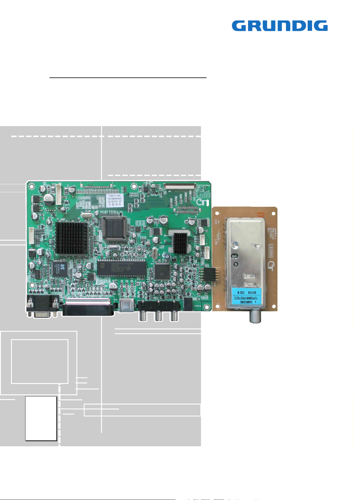
TV Service Manual
Chassis LA2000
20 LCD 51-7401 TOP
GBC9500
20 LCD 51-7402 TOP
GBD5200
Zusätzlich erforderliche Unterlagen für den Komplettservice
Additionally required Service Documents for the Complete Service
Service
Manual
Sicherheit
Safety
Materialnr./Part No.
720108000001
Materialnummer / Part Number 720100519000
Änderungen vorbehalten / Subject to alteration
H-S41 • 0605
http://www.grundig.com
NUR FÜR INTERNEN GEBRAUCH
FOR INTERNAL USE ONLY
Page 2
GRUNDIG Service Chassis LA2000
Es gelten die Vorschriften und Sicherheitshinweise
gemäß dem Service Manual "Sicherheit", Materialnummer 720108000001, sowie zusätzlich die eventuell abweichenden, landesspezifischen Vorschriften!
Inhaltsverzeichnis
Seite
Allgemeiner Teil ................................... 1-2…1-8
Messgeräte .................................................................................. 1-2
Allgemeine Hinweise.................................................................... 1-2
Technische Daten ........................................................................ 1-3
Bedienhinweise ............................................................................ 1-5
Platinenabbildungen
und Schaltpläne ................................... 2-1…2-6
Blockschaltplan ............................................................................ 2-1
Hauptplatte ................................................................................... 2-1
– Netzteil ..................................................................................... 2-3
– Prozessor ................................................................................. 2-3
– IN/OUT ..................................................................................... 2-4
– Scaler ....................................................................................... 2-5
– Teletext .................................................................................... 2-5
– Audio ........................................................................................ 2-6
Bedieneinheit, Kopfhöhrerplatte................................................... 2-6
The regulations and safety instructions shall be
valid as provided by the "Safety" Service Manual,
part number 720108000001, as well as the
respective national deviations.
Table of Contents
Page
General Section .................................... 1-2…1-8
Test Equipment ............................................................................ 1-2
General Notes .............................................................................. 1-2
Technical Data ............................................................................. 1-3
Operating Hints ............................................................................ 1-7
Layout of the PCBs
and Circuit Diagrams ........................... 2-1…2-6
Block Circuit Diagram .................................................................. 2-1
Main Board ................................................................................... 2-1
– Power Supply ........................................................................... 2-3
– Processor ................................................................................. 2-3
– IN/OUT ..................................................................................... 2-4
– Scaler ....................................................................................... 2-5
– Teletext .................................................................................... 2-5
– Audio ........................................................................................ 2-6
Keybaord, Headphone Board ...................................................... 2-6
Ersatzteillisten ...................................... 3-1…3-2
Allgemeiner Teil
Allgemeine Hinweise
Vor dem Öffnen des Gehäuses den Netzstecker ziehen!
Achtung: ESD-Vorschriften beachten
Leitungsverlegung
Bevor Sie die Leitungen und insbesondere die Masseleitungen lösen,
muss die Leitungsverlegung zu den einzelnen Baugruppen beachtet
werden.
Nach erfolgter Reparatur ist es notwendig, die Leitungsführung wieder
in den werkseitigen Zustand zu versetzen um evtl. spätere Ausfälle
oder Störungen zu vermeiden.
Durchführen von Messungen
Bei Messungen mit dem Oszilloskop an Halbleitern sollten Sie nur
Tastköpfe mit 10:1 - Teiler verwenden. Außerdem ist zu beachten,
dass nach vorheriger Messung mit AC-Kopplung der Koppelkondensator des Oszilloskops aufgeladen sein kann. Durch die Entladung
über das Messobjekt können Bauteile beschädigt werden.
Messwerte und Oszillogramme
Bei den in den Schaltplänen und Oszillogrammen angegebenen
Messwerten handelt es sich um Näherungswerte!
Spare Parts Lists .................................. 3-1…3-2
General Section
General Notes
Before opening the cabinet disconnect the mains plug!
Attention: Observe the ESD safety regulations
Wiring
Before disconnecting any leads and especially the earth connecting
leads observe the way they are routed to the individual assemblies.
On completion of the repairs the leads must be laid out as originally
fitted at the factory to avoid later failures or disturbances.
Carrying out Measurements
When making measurements on semi-conductors with an oscilloscope, ensure that the test probe is set to 10:1 dividing factor. If the
previous measurement was made on AC input, please note that the
coupling capacitor in the oscilloscope will be charged. Discharge via
the item being checked can damage the components.
Measured Values and Oscillograms
The measured values given in the circuit diagrams and oscillograms
are approximates!
1 - 2
Page 3
Chassis LA2000GRUNDIG Service
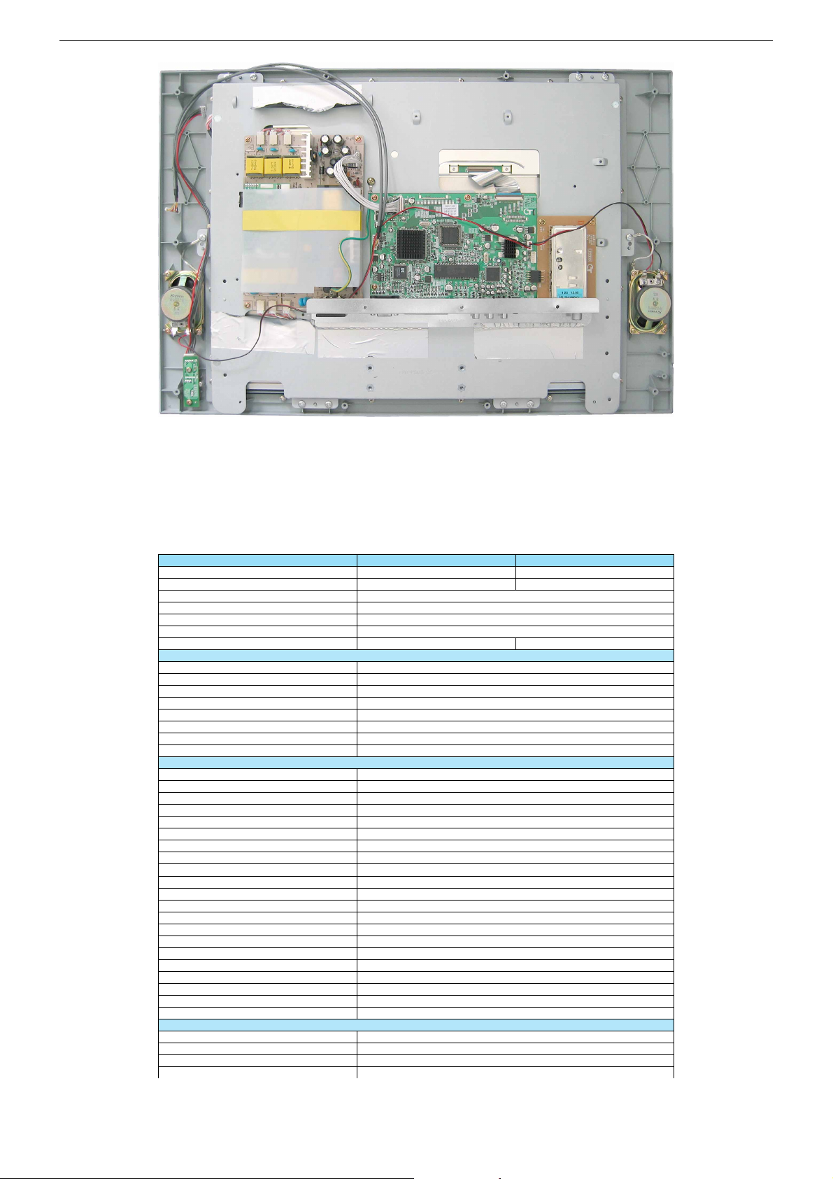
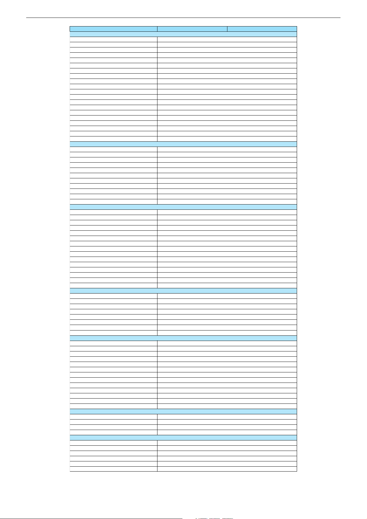
Technische Daten / Technical Data
Order No.
EAN
Approbations
IM-Languages
Destination
Remote control
Color
Display
Panel
16:9 wide-screen format
Panel driving technology
Response time
Brightness
Contrast ratio
Viewing angle approx.
Physical display resolution max. pixel
PICTURE
Digital Reference-Plus-Technology (Motion Adaption)
Line Flicker Reduction
Motion Adaptive Deinterlacing
Digital Color Transition Improv. (DCTI)
Digital Combfilter
Digital Luminance Transition Improv. (DLTI)
Picture Noise Reduction (DNR)
CCS (Clear Color Screen)
Preset picture modes
Aspect ratios (Format switching)
PIP
Multifold Tuner scan (Mosaic Picture)
PAT: Split screen (PICTURE + TEXT)
PAP: Double Window (PICTURE + PICTURE)
P2AT: Double window + TXT
POP: PICTURE on PICTURE
Picture freezing
Zoom with point function
Auto 16:9 selection via Scart
Sharpness control
Blue Background
CHASSIS
TV-Chassis
Progressive
Tuner
Keyboard 7 keys: stand-by, menu, ± for programme, ± for volume, AV-programme (lateral)
20 LCD 51-7401 TOP 20 LCD 51-7402 TOP
G.BC 95-00
40 13833-59873 2
G.BD 52-00
40 13833-60061 9
CE,C-TICK,ME67
D,GB,F,I,NL,DK,N,S,E
D,A,CH,F,I,E,NL,DK,FIN,N,S
RC 200
silver silver/black
20" / 51 cm Clear Color Screen Active Matrix TFT-LC-Display
\
MVA
ca. 16ms
ca. 600cd/m2
ca. 600:1
120° vertical / 160° horizontal
VGA 640 x 480
\
\
\
[
[
\
[
[
\
\
\
\
\
\
\
\
\
\
\
[
\
LA2000
PLL frequency synthesizer tuning
[
1 - 3
Page 4
Chassis LA2000GRUNDIG Service
ELECTRONIC
Stand by indicator
EPG (Electronic Programme Guide)
Easy Dialog
Megalogic
Manual & autom. labeling of prog.
Programmable off timer
Programmable on timer
Intelligent channel search (Zapping funct.)
Programme Edit
Intelligent Programme Switch
Auto switch off
Programme memory TV/AV (opt.)
Teletext/Fasttext/Toptext
Teletext options
Childlock
Youth free recognition
Menu languages OSD
SWAP (Recall function)
Service mode
Hotel mode
TUNING
Autom. Tuning System with country selection
Frequency Based Auto Search
Automatic Micro-search
Automatic Programming
Manual fine tuning
Direct channel selection
Direct frequency selection
PAL/SECAM/BG/DK/I/L’/L
NTSC-Playback via Scart (3,58/4,43)
PAL M/N, NTSC M
Cable TV / Hyperband (S1-S41)
AUDIO
Mono/Stereo/Nicam
AV Stereo
Loudspeaker
Virtual Dolby
Matched Sound Delay (Lip synchronous)
Subwoofer
Dynamic Bass
DSP (Digital Sound Processor)
Balance Adjustment
AVL (Audio Volume Level)
PIP listening via Headphone.jack
Equalizer
Space Sound Effect
Audio mode
Audio amplifier without extern LS
POWER SUPPLY / CABINET
Power voltage
Range of regulation
Power switch
Integrated supply
Plug-in AC adaptor
Power consumption
Cabinet (WxHxD)
Weight
REAR PANEL CONNECTIONS
Euro-AV-Socket AV1
Euro-AV Socket AV2
Euro-AV Socket AV3
S-Video
Camera-AV
Wireless
YUV input / progressive
PC-input (Sub D 15)
PC-Audio in
DVI
HDCP
HDMI
Headphones
REAR PANEL CONNECTIONS
Audio out
Antenna for terrestrial reception
DC-connector
Power supply plug
SUPPLIED ACCESSORIES
Remote control (incl. battery)
Power cord
Cables
Instruction manual
Circuit diagram
Wall fixture integrated
20 LCD 51-7401 TOP 20 LCD 51-7402 TOP
[
\
\
\
[
[
[
\
[
\
\
99 / 6
[ / [ / [
10 pages
\
\
6 languages: D, GB, F, I, E, NL
\
[
\
, full automatic sorting
[
\
\
\
[
\
\
[
[
\
[
/ [ / [
[
[
2 wide band at the front side
\
\
\
\
\
[
\
\
[, 5 Band
\
Yes, user, music, cinema, speech
2 x 5 / 3.5W (music/nominal)
230V
100-240V, 50/60Hz, in accordance to IEC 65
\
Ye s
\
50W, stand-by < 5W
58,5 x 44 x 7cm (19cm with stand)
ca. 10kg
CVBS in-/output, Audio in/output , RGB input
\
\
Yes, (Hosiden)
Yes, 3x Cinch socket in
\
Yes, via Scart
Yes, (Multisync SVGA)
Yes, 3,5mm jack Stereo
\
\
\
\
\
1 x Coaxial-socket for TV-tuner-in, according to DIN 45325
\
Power cord plug-in type
[
[
\
[
\
\
1 - 4
Page 5
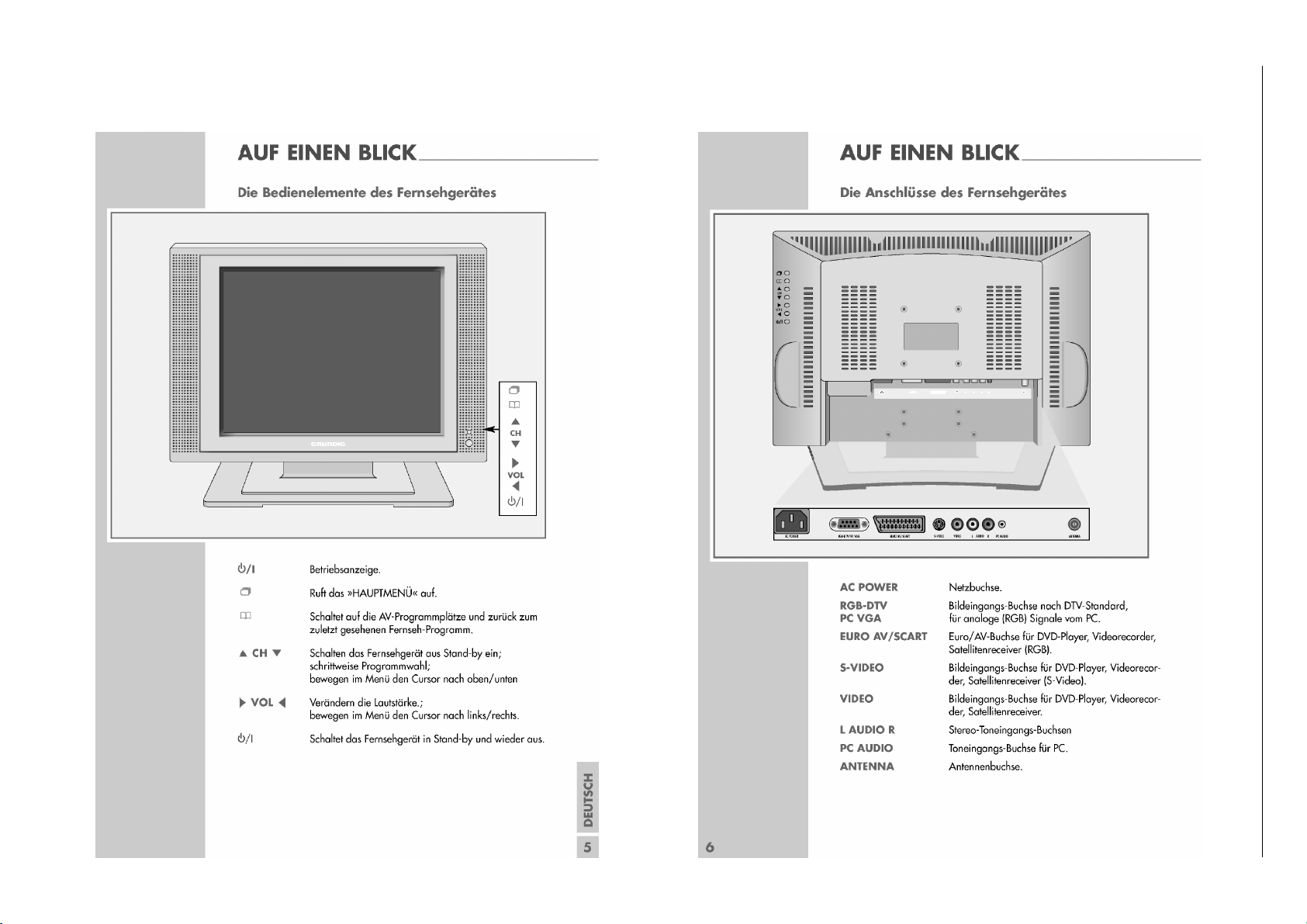
Bedienhinweise Dieses Kapitel enthält Auszüge aus der Bedienungsanleitung.
Weitergehende Informationen entnehmen Sie bitte der gerätespezifischen Bedienungsanleitung, deren Materialnummer Sie in der entsprechenden Ersatzteilliste finden.
1 - 5
Chassis LA2000GRUNDIG Service
Page 6

1 - 6
Chassis LA2000GRUNDIG Service
Page 7

Operating Hints This chapter contains excerpts from the operating instructions.
For further particulars please refer to the appropriate user instructions the part number of which is indicated in the relevant spare parts list.
1 - 7
Chassis LA2000GRUNDIG Service
Page 8

1 - 8
Chassis LA2000GRUNDIG Service
Page 9

GRUNDIG Service Chassis LA2000
Platinenabbildungen und Schaltpläne / Layout of PCBs and Circuit Diagrams
Blockschaltplan / Block Circuit Diagram
Analog RGB
VGAHS/VS
Tuner
CVBS
Composite
(CVBS)
Full SCART
CVBS IO
Full SCART
RGB/FB
S-Video
PC
Audio IN
Full SCART
Audio IN/OUT
Audio
SL/SR
Tuner
SIF
Tuner
Mono
R G B 3
U202
2
74VHC14
CVBS CVBS2
TUNER_ON
CVBS
CVBS1
SC_CVBS
SC_RGB/FB 4
S-CHROMA / S-LUMA 2
PC_SL/PC_SR 2
SC_SL/SC_SR
SC_SLO/SC_SRO 2
VGAHS/VS
2
2
STV8216
U601
2
U201
AD9883A
SCLK
SDAT
EEPROM
AUDIO_RESET
AUDIO_ON
HPL/R
R G B 24
U402
2
2
U602
Audio Amp.
CN8
Headphone
SCLK
SDAT
AMP_OFF
FPR/G/B 24
FPVS
FPHS
FPDE
U101
TW8801
Scaler
MTV230
Processor
FPCLK
PPWR
TELE_RGB
CVBS0
SCALER_RESET
7
U401
+12V VCC5T VCC8 VCC5 +5V
U805 U806
+12V +8V +5V
3
Keyboard
U403
IR-Receiver
U302
SAA5264
Teletext
TFT LCD
VCC3 AVCC3 VCC3AD
U603
U802 U801
U807
Backlight
InverterPOWER SUPPLY BOARD
Hauptplatte / Main Board
Ansicht von der Bestückungsseite / View of Component Side
2 - 1
Page 10

2 - 2
GRUNDIG Service Chassis LA2000
Hauptplatte / Main Board
Vergrößerte Ansicht von der Bestückungsseite / Larged view of Component Side
Page 11

GRUNDIG Service Chassis LA2000
4
Hauptplatte – Netzteil / Main Board – Power Supply
TO POWER SUPPLY BOARD
Hauptplatte – Prozessor / Main Board – Processor
P1.0 -7
P3.0 -2
P3.4 -5
P4.0 -7
P5.0 -7
RST
X1
X2
MTV230M
8051
CORE
P0.0 -7
P2.0 -3
INT1
P0.0 -7
P2.0 -3
RD
RD
WR
ALE
INT1
AD0-3
PWM DA C
XFR
ADC
DA0-3
WR
ALE
CONTROL
H/VSYNC
CONTROL
DDC & II C
INTERFACE
OSD
OSDHS
OSDVS
ROUT
GOUT
BOUT
FBKG
HSYNC
VSYNC
HBLANK
VBLAN K
ISDA
HSCL
HSDA
XIN
INT
TO KEYBOARD
ISCL
15
3
2
4
1
power on (trigger: +12V)
1
power on (trigger: +12V)
2
3
4
3
%
2 - 3
Page 12

GRUNDIG Service Chassis LA2000
3
5
Hauptplatte / Main Board – IN/OUT
3
TO TUNER
4
4
6
5
6
2 - 4
1
A
S
S2A
1
B
S
S2B
1
C
S
S2C
1
D
S
S2D
DECODER/DRIVERS
EN IN
R
CLAMP
AIN
G
CLAMP
AIN
B
CLAMP
HSYNC
COAST
CLAMP
FILT
SCL
SDA
AIN
A
0
SYNC
PROCESSING
AND CLOCK
GENERATION
SERIAL REGISTER
AND
POWER MANAGEMENT
D
A
D
B
D
C
D
D
A/D
A/D
A/D
REF
AD9883A
8
R
OUTA
8
G
OUTA
8
B
OUTA
MIDSCV
DTACK
HSOUT
VSOUT
SOGOUT
REF
BYPASS
Page 13

GRUNDIG Service Chassis LA2000
power on (trigger: +12V)
1
4
7 8 9
@
Hauptplatte / Main Board – Scaler
7
$
%
^
2
I
C-bus,
general I/O
CVBS
CVBS
ROM
DRAM
DATA
CAPTURE
DATA
CAPTURE
TIMING
TV CONTROL
AND
INTERFACE
MICROCONTROLLER
(80C51)
MEMORY
INTERFACE
DISPLAY
DISPLAY
TIMING
14
SRAM
SAA5264
SAA5265
TO DISPLAY
11
10
6
9
8
15
16
12
13
1
3
3
4
6
R
G
B
VDS
VSYNC
HSYNC
Hauptplatte / Main Board – Teletext
14
4
3
13
12
2 - 5
!
0
#
Page 14

GRUNDIG Service Chassis LA2000
*
Hauptplatte / Main Board – Audio
17
TO HEADPHONE
Sound IF
SIF
Mono In
MONOIN
AI1L
AI1R
AI2L
AI2R
Input SCARTs
AI3L
AI3R
STV82x6
Demodulation
AGC
0.5V
rms
2V
rms
2V
rms
2V
rms
A/D
3
4
Multi-Standard
Digital Stereo
Demodulator
Input
Analog
Audio
Matrix
IRQ
Request
Interrupt
FM, AM, A2
and NICAM
Stereo
SDO
ST
Flag
Audio
Stereo
A/D
Stereo
Flag
WS
IS Interface IS Interface
Digital
Audio
Matrix
Source Preprocessing
Single Crystal
Clock Generation
SDA
SCK
Loudspeaker Audio Processing
Smart Volume Control, ST WideSurround,
5-band Equalizer and Loudness,
Headphone Audio Processing
Audio Matrixing
SCL
Audio Processing
Beeper and Subwoofer Output
Smart Volume Control,
Bass/Treble and Beeper
Power Supply Management
DC Regulators, Standby mode
2
18
BUS1
BUS0
IC Bus Expander
Audio
Stereo
D/A
Audio
Stereo
D/A
Audio
Stereo
D/A
Vol./
Bal.
Vol./
Bal.
Output
Analog
Audio
Matrix
Gain
HPD
Headphone
Detection
Low Noise
Audio Mute
Low Noise
Audio Mute
Low Noise
Audio Mute
Low Noise
Audio Mute
19
20
VCCV
CC
TDA7266
4
IN1
ST-BY 7
Loudspeaker
LSL
1V
rms
LSR
SW
Subwoofer
Headphone
HPL
1V
rms
HPR
AO1L
2V
rms
AO1R
AO2L
2V
rms
AO2R
Output Scarts
9
S-GND
12
IN2 +
MUTE 6
PW-GND
8
Vref
133
+
1
-
+
-
+
OUT1+
2
OUT1-
15
OUT2+
14
OUT2-
XTI
XTO
power on (trigger: +12V)
2
3
4
&
)
Bedieneinheit, Kopfhörerplatte / Keyboard, Headphone Board
TO MAIN BOARD
(
TO MAIN BOARD
HEADPHONEKEYBOARD
2 - 6
Page 15

GRUNDIG Service Chassis LA2000
ǵ
Ersatzteilliste
Spare Parts List
4 / 2005
POS. NR. ABB. MATERIAL-NR. ANZ. BEZEICHNUNG DESCRIPTION
POS. NO. FIG. PART NUMBER QTY.
720126012400 20 LCD 51-7401 TOP 20 LCD 51-7401 TOP
0001.000 759551144200 GEHAEUSEVORDERTEIL SILBER FRONT CABINET SILVER
0002.000 759551144100 RUECKWAND SILBER BACK COVER SILVER
0003.000 759551144300 DEKO-RAHMEN VORDERTEIL SILBER DECO FRAME FRONT SILVER
0005.000 759551144400 FUSS SILBER FOOT SILVER
0007.000 759551146500 LAUTSPRECHER LOUDSPEAKER
0008.000 S 759551143500 LCD-DISPLAY 20" CHI MEI LCD-DISPLAY 20" CHI MEI
0019.000 759551146700 TUNER TCPQ9091 PD27D TUNER TCPQ9091 PD27D
0020.000 720117137100 FERNBEDIENUNG REMOTE CONTROL
0021.000 759551143900 KABEL BEDIENMODUL CABLE CONTROLBOARD
0022.000 759551144000 DATENKABEL (Display) DATA CABLE (Display)
0025.000 S 759551144800 NETZKABEL POWER CABLE
0030.000 759551143800 LP-HAUPTMODUL MAINBOARD
0060.000 759551143600 LP-BEDIENMODUL CONTROLBOARD
0070.000 S 759551146600 LP-NETZTEIL POWER SUPPLY
0080.000 759551143700 LP-IR-MODUL IR-BOARD
0090.000 759551144500 POLSTERSET LCD CUSHION SET LCD
0091.000 759551144600 KARTON CARTON
0092.000 759551144700 POLSTERSET FUSS CUSHION SET FOOT
NUR FÜR INTERNEN GEBRAUCH
FOR INTERNAL USE ONLY
20 LCD 51-7401 TOP
MATERIAL-NR. / PART NO.: 720126012400
BESTELL-NR. / ORDER NO.: GBC9500
d©
KEIN E-TEIL NO SPARE PART
TV
720117106500 BEDIENUNGSANLEITUNG D/F/I INSTRUCTION MANUAL D/F/I
720117106600 BEDIENUNGSANLEITUNG GB/NL/E INSTRUCTION MANUAL GB/NL/E
720117106700 BEDIENUNGSANLEITUNG S/DK/N INSTRUCTION MANUAL S/DK/N
720100519000 SERVICE MANUAL D/GB SERVICE MANUAL D/GB
Es gelten die Vorschriften und Sicherheitshinweise
gemäß dem Service Manual "Sicherheit", Mat.-Nummer 720108000001, sowie zusätzlich die eventuell abweichenden, landesspezifischen Vorschriften!
!
( ! )
3 - 1
The regulations and safety instructions shall be valid
as provided by the "Safety" Service Manual, part
number 720108000001, as well as the respective
national deviations.
ÄNDERUNGEN VORBEHALTEN / SUBJECT TO ALTERATION
Page 16

GRUNDIG Service Chassis LA2000
ǵ
Ersatzteilliste
Spare Parts List
6 / 2005
POS. NR. ABB. MATERIAL-NR. ANZ. BEZEICHNUNG DESCRIPTION
POS. NO. FIG. PART NUMBER QTY.
720126015600 20 LCD 51-7402 TOP 20 LCD 51-7402 TOP
0001.000 759551144200 GEHAEUSEVORDERTEIL SILBER FRONT CABINET SILVER
0002.000 759551144100 RUECKWAND SILBER BACK COVER SILVER
0003.000 759551167300 DEKO-RAHMEN VORDERTEIL SILBER DECO FRAME FRONT SILVER
0005.000 759551167400 FUSS SILBER FOOT SILVER
0007.000 759551146500 LAUTSPRECHER LOUDSPEAKER
0008.000 S 759551143500 LCD-DISPLAY 20" CHI MEI LCD-DISPLAY 20" CHI MEI
0019.000 759551146700 TUNER TCPQ9091 PD27D TUNER TCPQ9091 PD27D
0020.000 720117137100 FERNBEDIENUNG REMOTE CONTROL
0021.000 759551143900 KABEL BEDIENMODUL CABLE CONTROLBOARD
0022.000 759551144000 DATENKABEL (Display) DATA CABLE (Display)
0025.000 S 759551144800 NETZKABEL POWER CABLE
0030.000 759551143800 LP-HAUPTMODUL MAINBOARD
0060.000 759551143600 LP-BEDIENMODUL CONTROLBOARD
0070.000 S 759551146600 LP-NETZTEIL POWER SUPPLY
0080.000 759551143700 LP-IR-MODUL IR-BOARD
0090.000 759551144500 POLSTERSET LCD CUSHION SET LCD
0091.000 759551144600 KARTON CARTON
0092.000 759551144700 POLSTERSET FUSS CUSHION SET FOOT
NUR FÜR INTERNEN GEBRAUCH
FOR INTERNAL USE ONLY
20 LCD 51-7402 TOP
MATERIAL-NR. / PART NO.: 720126015600
BESTELL-NR. / ORDER NO.: GBD5200
d©
KEIN E-TEIL NO SPARE PART
TV
720117106500 BEDIENUNGSANLEITUNG D/F/I INSTRUCTION MANUAL D/F/I
720117106600 BEDIENUNGSANLEITUNG GB/NL/E INSTRUCTION MANUAL GB/NL/E
720117106700 BEDIENUNGSANLEITUNG S/DK/N INSTRUCTION MANUAL S/DK/N
720100519000 SERVICE MANUAL D/GB SERVICE MANUAL D/GB
Es gelten die Vorschriften und Sicherheitshinweise
gemäß dem Service Manual "Sicherheit", Mat.-Nummer 720108000001, sowie zusätzlich die eventuell abweichenden, landesspezifischen Vorschriften!
!
( ! )
3 - 2
The regulations and safety instructions shall be valid
as provided by the "Safety" Service Manual, part
number 720108000001, as well as the respective
national deviations.
ÄNDERUNGEN VORBEHALTEN / SUBJECT TO ALTERATION
 Loading...