

Page 1

HYDROGEN-SERIES
Mono Amplifier
Owner’s manual
GZHA MINI ONE-K
Features
• High-efficient class D amplifier technology
• Installer friendly dimensions
• 1 ohms stable / 2 ohms (in linked configuration)
• High-level input with auto-on function
• 12 dB adjustable bass boost (@45 Hz)
• Adjustable low pass filter
• Adjustable input sensitivity
• Adjustable subsonic filter
• 0° / 180° Phase shift switch
• Bass remote control
• Thermal / short circuit / overload protection
Page 2

2
Gerenal mounting instructions
• As a precaution, it is recommended to disconnect the vehicles battery before mounting the
amplifier. (Note: For new vehicles, disconnecting the battery might cause various errors in
your vehicle´s electric system that can be cleared only by authorized service partners of your
vehicle´s manufacturer! Please ask your service partner first before disconnecting the battery!)
• The power supply wire (+12 V) has to be protected within max. 20 cm / 8” by a main fuse
holder with a fuse value matching the recommendation for your amplifier
(Note: If there is more than one amplifier connected using this power wire, the main fuse
value must be equal to the sum of the recommended fuses of all connected devices. However,
make sure the diameter of your power wire will be sufficient for the required current!)
• If necessary, replace a defective fuse by a fuse with identical quality and value
• Never drill a hole to the vehicles gas tank or brake lines, to wirings or any other important
vehicle parts!
• Never pass wires over sharp edges or vehicle parts due avoid any kind of damage
• Keep the wiring away from the antenna and electronic devices contributing to radio reception
• Lay the power supply wiring always separated from speaker wiring to avoid disturbance
• The amplifier contains a temperature protection circuit that turns the device off in case of
overheating. After a certain cooling time, it will turn on automatically. To avoid heat build-up,
sufficient air supply for cooling must be provided. Never cover the surface of the amplifier´s
heatsink entirely
• The amplifier should
NEVER be mounted onto a vibrating part or surface such as a subwoofer
enclosure. This might lead to malfunction due to loosened electrical parts inside the amplifier.
• Some amplifiers offer a high-level input option, however if a pre-amplified output (RCA) is
available (at the head unit), it is strongly recommended to make use of them.
Page 3
3
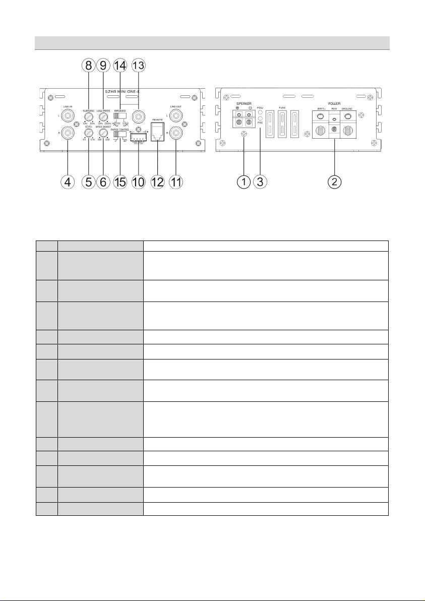
1
SPEAKER terminal
2
POWER supply terminal
3
Status LEDs
4
LINE-IN (RCA input)
Attention
never
5
LEVEL control
6
BASS BOOST control
8
SUBSONIC filter
9
LOW-PASS (LPF) control
10
HIGH LEVEL input
Attention
never
11
LINE OUT / OUTPUT
12
REMOTE socket
13
BRIDGED socket
14
BRIDGED mode switch
(MASTER / SLAVE)
15
PHASE CONTROL switch
Speaker connection
GROUND - ground terminal
REM - re mote wire / not to be used together with high -level input
BATT+ - +12 Volt wire from battery terminal
POW - green -> ok (correct operation)
PRO - red -> error / protection
Input sockets to connect RCA wires - to avoid any malfunction, it is recommended to use
only high-quality RCA cables.
simultaneously! This may cause serious damage to the amplifier
Controller to adjust the input sensitivity
Controller to adjust the bass boost level (0 to +12 dB at 45 Hz)
To adjust the required crossover for subsonic frequencies. Those frequencies below the
selected crossover point will be filtered (10 Hz to 50 Hz).
To adjust the required crossover point. Frequencies above the selected crossover point w ill
be filtered (30 Hz to 250 Hz)
As an alternative to the RCA inp ut (4), the high-level input can be used to connect the
speaker output of the head unit directly. The amplifier turns on automatically (Auto-On) while
the REM (remote) input of the power supply terminal remains unused.
and RCA inputs must
Fullrange RCA output to connect further amplifiers
To connect the bass remote control
To connect an RCA cable for link mode operation
High quality RCA cable is recommended (max. 1.5m / 4.9 ft)
To select the operation mode of the amplifier (see also link mode diagram)
To select the phase of the connected subwoofer in relation to further speakers (0° / 180°)
: High-level and RCA inputs should
be used simultaneously! This may cause damage to the amplifier
be used
: High-level
Controls & Features
Page 4

4
High-level input wiring
RCA input wiring
Page 5

5
Ø min. 4 mm² / 11 AWG
Link mode mode wiring
Page 6

6
Specifications
Model
GZHA MINI ONE-K
Type
RMS Power @ 4 Ω
CEA Standard CEA-2006-A
RMS Power @ 2 Ω
CEA Standard CEA-2006-A
RMS Power @ 1 Ω
CEA Standard CEA-2006-A
RMS Power @ 2Ω link mode
CEA Sta ndard CEA-2006-A
Damping factor
Low pass crossover
High pass crossover (subsonic)
Band pass crossover
Bass boost
Frequency range
10 Hz – 250 Hz
(± 1 dB)
Input sensitivity
Bass remote control
Fuse(s)
Dimensions (B x H x L)
5.32 x 2.05 x 12.68”
Mono Class D
340 W (1% THD+N)
600 W (1% THD+N)
1000 W (1% THD+N)
2000 W (1% THD+N)
2300 W (10% THD+N)
> 100
30 Hz – 250 Hz (24 dB/Octave)
10 Hz – 50 Hz (24 dB/Octave)
10 Hz – 250 Hz (24 dB/Octave)
0 ~ +12 dB (45 Hz)
300 mV – 6 V
(± 5%)
3 x 35 A
135 x 52 x 322 mm
Page 7

7
Symptoms
Check / Cause
Action
Device turns
No audible
sound
Device does
not turn on
No sound on
one channel
Does the POW LED turn to green?
Did the PRO LED turned to red? Check for speaker short or amplifier overheating
Power supply of the amplifier? Check power wire or connections
Remote wire powered? (RCA input mode) Check remote wire connection to the head unit
Speaker wiring undamaged? Check for short circuit or open connections
Input signal on both RCA leads?
Check protection fuse(s) of the amplifier
Check remote wire connection (RCA input mode)
Check +12 Volt power supply wire connection
Check ground wire connection
Reverse left and right RCA inputs to check the
audio input signal
Trouble shooting guide
off at
medium /
high volume
Status LED
turned on
red
Load impedance of each speaker correct?
Temperature protection circuit active Decrease head units volume / wait for cooling
Speaker wires short / speaker damaged Check speaker / wires and insulate if necessary
Check if each speaker load impedance matches
the technical specifications of the amplifier
Page 8

8
Terms of warranty
The limited warranty for this product is covered by Ground Zero´s local distribution partners and their
terms and conditions. For further information contact your local retailer or distributor.
Ground Zero GmbH
Erlenweg 25, 85658 Egmating, Germany
Tel. +49 (0)8095/873 830 Fax -8310
www.ground-zero-audio.com
 Loading...