

Ground Zero HYDROGEN GZHA 2350XII, HYDROGEN GZHA 4150XII, HYDROGEN GZHA 5125XII Owner's Manual
Page 1

Amplifier
Owner’s Manual
HYDROGEN
GZHA 2350XII
GZHA 4150XII
GZHA 5125XII
PLEASE READ BEFORE INSTALLATION
Thank you for selecting a Ground Zero amplifier.
We are providing a helpful hints list which should keep you from experiencing
unnecessary shut down.
Have fun with this high quality Hydrogen product.
Features
• 4 Ohm / 2 Ohm stable stereo
• 1 Ohm stable stereo (GZHA 2350XII / Channel 5 of GZHA 5125XII)
• P.W.M. Mosfet power supply
• SMD Technology
• Power & Protection indicator
• Variable 12dB Bass Boost (GZHA 2350XII)
• Variable high pass filter
• Variable low pass filter
• Variable subsonic filter
• Variable phase shift 0 ~ 180°
• Switchable phase shift 0° / 180° (GZHA 5125XII)
• Adjustable input sensitivity
• Soft delayed remote turn- on
• RCA outputs (GZHA 4150XII)
• Remote control
• Thermal / Short / Overload protection
2
Page 2

Hydrogen amplifiers
Due to their state- of- the- art technology and high efficiency, these amplifiers help your system to provide an
impressive sound experience. The modern circuit technology of the power supply and the signal processing allows
achieving maximum performance levels from the provided power.
Tools and materials you need
• Screwdriver
• Electric drill, 3 mm / 0.12” carbide drill bit
• Mounting screws
• Power wire min. 16 mm² / 5 AWG
• Ground wire min. 16 mm² / 5 AWG
• Speaker wire min. 2 x 1,5 mm² / 15 AWG
Please note!
• As a precaution it is advisable to disconnect the vehicle’s battery before making connection
to the +12 Volts supply wiring (see owner’s manual of your car for further information).
• Please use great caution drilling your trunk. Your gas tank and brake lines can be damaged by
puncturing with your drill bit – this could cause damage or failure of your cars operating systems.
• Never pass wires over sharp angles. It is recommended to buffer the power supply of the amplifier
with an capacitor min. 1 Farad to guarantee a stable operation voltage.
WARNING !
High powered audio systems in a vehicle are capable of generating "Live Concert" levels of sound pressure.
Continued exposure to excessively high volume sound levels may cause hearing loss or damage. Also, operation
of a motor vehicle while listening to audio equipment at high volume levels may impair your ability to hear
external sounds such as; horns, warning signals, or emergency vehicles, thus constituting to a potential traffic
hazard. In the interest of safety, Consumer Electronics recommends listening at lower volume levels while driving.
Planning your system
Before beginning the installation, consider the following:
a. If you plan to expand your system by adding other components sometime in the future, ensure
adequate space is left, and cooling requirements are met.
b. If your radio / source is equipped with pre-amp outputs, it is possible to utilize them to drive the
amplifier and connecting (amplifier) to the 2 rear speakers.
Mounting your amplifier
a. Select a suitable location that is convenient for mounting, is accessible for wiring
and has ample room for air circulation and cooling.
b. Use the amplifier as a template to mark the mounting holes, remove the amplifier
Warning
Chose a mounting position where all eclectic wires are protected from being damaged by sharp edges, heat or
other conditions. +12Volt DC electrical connections must be fused on the battery side. Make sure your radio and
all other devices will be turned off while connection your system.
If you need to replace the power fuse, replace it only with a fuse identical to that supplied with the system. Using
a fuse of different type or rating may result in damage to this system which isn’t covered by the warranty.
3
4
Page 3
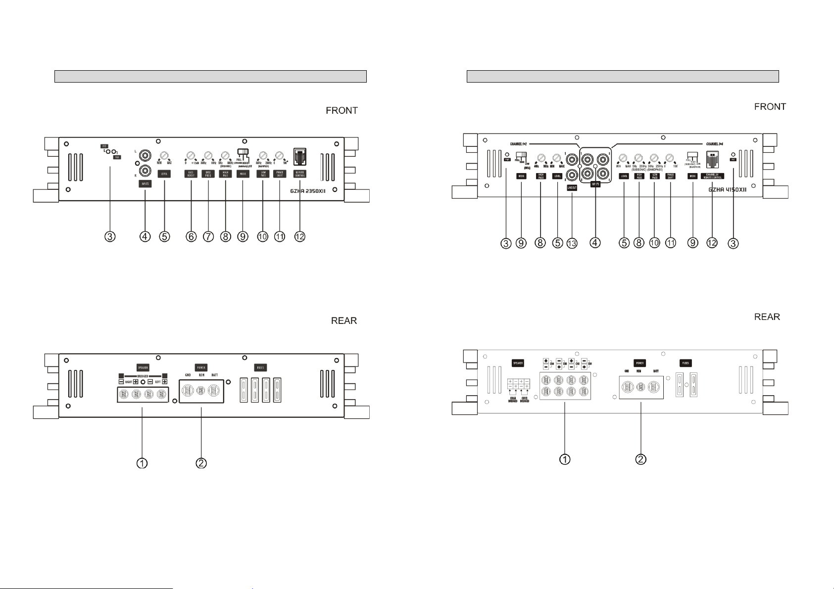
Controls and functions – GZHA 2350XII
Controls and functions – GZHA 4150XII
5
6
Page 4

r
r
r
A
r
Controls and functions – GZHA 5125XII
Controls and functions
1 Speaker terminals For connection of the speakers
Power terminals
2
3 Satus indication
4 Cinch inputs
5 Input level controlle
Bass boost controlle
6
(GZHA 2350XII)
Bass frequency controlle
7
(GZHA 2350XII)
High pass controller
8
(Subsonic for GZHA 2350XII
and CH 3+4 GZHA 4150XII)
9 Mode switch
10 Low pass controller
Phase shift switch
(GZHA 5125XII)
11
Phase shift controller
(GZHA 2350XII / 4150XII)
12 Remote control input For connection of the bass remote control.
Cinch outputs
13
(GZHA 4150XII)
14 Filter controller
Subsonic controlle
15
(GZHA 5125XII)
Input switch
16
(GZHA 5125XII)
GND -> Ground connection
REM -> Remote antenna terminal
BATT -> +12 Volt
BLUE–OK
RED – Error
Terminal for connection of the RCA wires.
To avoid failure, please use high quality RCA wires.
With this controller you can adjustthe input sensitivity.
For adjusting of the bass boost level in the range from 0 to +12 dB.
For adjusting of the bass boost frequency in a range from 30 to 80 Hz.
Setthe filter switch to „HIGH“ position.
Adjust the variable HPF crossover frequency to the desired frequency
using the controller. All frequency between 5 and 3000 Hz will be
reproduced.
djust the crossover for the chosen utilization.
LPF – Only bass frequencies (below 30Hz - 250Hz) will be reproduced.
FULL – All frequencies will be reproduced.
HPF – Only middle and high frequencies (over 40 Hz – 3 KHz) will be
reproduced.
GZHA 2350XII / GZHA 4150XII CH 3+4:
At LPF adjustment, also the Highpass (Subsonic) is activated.
This equals a Bandpass filter of 5 – 250 Hz.
GZHA 4150XII CH 1+2
The Lowpass filter is not adjustable. It is fixed at 80 Hz.
For subwoofer and Kickwoofer operation Only frequencies from 30 Hz to 250 Hz will be reproduced (depending
on the LPF filter controller position). Set the filter switch to „LOW“
position. Adjust the variable LPF frequency to the desired frequency
using the controller.
GZHA 2350XII / GZHA 4150XII CH 3+4:
At LPF adjustment, also the Highpass (Subsonic) is activated.
This equals a Bandpass filter of 5 – 250 Hz.
This controller allows you to fit the subwoofer channel in-phase to the
front system.
For fullrange operation of an additional amplifier.
With this controller you can adjust the filter frequency according to
the setting of the mode switch (9).
For adjusting the subsonic filter in a range from 5 Hz to 50 Hz.
With this chose if the 5. Channel should be powered by the cinch input
5/6 or the sum of signals from 1/2/3/4.
7
8
Page 5

Turning on the amplifier
The amplifier automatically turns on a few seconds after you turn on your radio.
Note: Your amplifier temporarily shuts down if it gets too hot, then restarts automatically once it cools
(At about 80° / 176° F).
Adjusting the audio level
1. LEVEL (Min/Max): Turn fully counter- clockwise to MIN position
2. Turn the auto sound system's volume control to about two-third of its full range.
3. Adjust LEVEL to a comfortable listening level.
Connecting the speaker for trimode operation - notes
TRI MODE operation output allows a subwoofer to be operated in mono mode while the main speakers are
playing in stereo. Leave the crossover switch on “Full” position.
Use 100 volt, non-polar capacitors for a high pass crossover to filter out low frequencies and Air- core or
Ferrit- ore coils with a minimum diameter of 1 mm / 0.039” for the lowpass crossover to filter out high
frequencies.
The capacitor and inductor values as written in the below table. The front and rear channels of this amplifier get
this capability. Only the rear left and right channels are shown on the following pictures.
Values for 6dB passive crossover
Frequency Inductor Capacitor
80 Hz 7,5 mH 470 uF
100 Hz 6,5 mH 330 uF
120 Hz 5,5 mH 370 uF
150 Hz 4 mH 220 uF
Connecting the speaker – GZHA 2350XII
9
10
Page 6

Trimode operation – GZHA 2350XII
Connecting the speaker – GZHA 4150XII
11
12
Page 7

Trimode operation – GZHA 4150XII
Connecting the speaker – GZHA 5125XII
13
14
Page 8

Connecting the speaker – GZHA 5125XII (Bridged)
Trimode operation – GZHA 5125XII
15
16
Page 9

Specifications
Model GZHA 2350XII GZHA 4150XII
RMS Power @ 4 Ω
CEA Standard CEA-2006-A
RMS Power @ 2 Ω
CEA Standard CEA-2006-A
RMS Power @ 1 Ω
CEA Standard CEA-2006-A
RMS Power @ 4Ω bridged
CEA Standard CEA-2006-A
RMS Power @ 2Ω bridged
CEA Standard CEA-2006-A
Damping factor
Signal to noise Ratio
Lowpass
Highpass
Bandpass
Subsonic filter
Bass boost
Bass boost frequency
Phase shift
Frequency response
Efficiency @ 4 Ω
Input sensitivity
Channel separation
THD
Bass remote
Fuse
Dimensions
W x H x L mm
Dimensions
W x H x L inch
2 x 260W (1% THD+N)
2 x 320W (10% THD+N)
2 x 470W (1% THD+N)
2 x 570W (10% THD+N)
2 x 740W (1% THD+N)
2 x 900W (10% THD+N)
1 x 940W (1% THD+N)
1 x 1140W (10% THD+N)
1 x 1480W (1% THD+N)
1 x 1800W (10% THD+N)
> 200 > 130 > 120 > 70
> 70 dB > 70 dB > 70 dB
30 Hz – 250 Hz
5 Hz – 500 Hz
5 Hz – 250 Hz
5 Hz – 500 Hz
0 ~ +12 dB --- --- ---
30 Hz ~ 80 Hz --- --- ---
0 – 180°
10 Hz – 38 KHz
(± 1 dB)
~ 80 % ~ 80 % ~ 80 %
200 mV – 9 V
(± 5%)
50 dB 50 dB 50 dB
< 0,10 % < 0,10 % < 0,10 %
At lowpass- operation
4 x 40A 2 x 40A 3 x 40A
305 x 62 x 400 305 x 62 x 400 305 x 62 x 500
12 x 2.44 x 15.75“ 12 x 2.44 x 15.75“ 12 x 2.44 x 19.69“
4 x 130W (1% THD+N)
4 x 160W (10% THD+N)
4 x 200W (1% THD+N)
4 x 250W (10% THD+N)
--- ---
2 x 400W (1% THD+N)
2 x 500W (10% THD+N)
--- --- ---
80 Hz
( Channel 1 & 2 )
30 Hz – 250 Hz
( Channel 3 & 4 )
40 Hz – 3 kHz
( Channel 1 & 2 )
5 Hz – 250 Hz
( Channel 3 & 4 )
5 Hz – 250 Hz
( Channel 3 & 4 )
5 Hz – 250 Hz
( Channel 3 & 4 )
0 – 180°
( Channel 3 & 4 )
10 Hz – 38 KHz
(± 1 dB)
200 mV – 9 V
(± 5%)
( Channel 3 & 4 )
GZHA 5125XII
Channel 1-4 Channel 5
4 x 100W (1% THD+N)
4 x 120W (10% THD+N)
4 x 150W (1% THD+N)
4 x 200W (10% THD+N)
2 x 300W (1% THD+N)
2 x 400W (10% THD+N)
40 Hz – 3 kHz
( Channel 3 & 4 )
40 Hz – 3 kHz
( Channel 1 – 4 )
--- 5 Hz – 250 Hz
--- 5 Hz – 50 Hz
--- 0 – 180°
10 Hz – 22 KHz
(± 1 dB)
---
1 x 270W (1% THD+N)
1x 380W (10% THD+N)
1 x 430W (1% THD+N)
1 x 620W (10% THD+N)
1 x 600W (1% THD+N)
1 x 900W (10% THD+N)
200 mV – 9 V
(± 5%)
At lowpass- operation
30 Hz – 250 Hz
10 Hz – 250 Hz
---
---
(± 1 dB)
Trouble shooting guide
Symptoms Check Points Cure
No sound
Amp not switching on
No sound in one channel
Amp turning off at medium /
high volume
Protection LED is on
Check fuses in amplifier.
Be sure remote lead is connected.
Is the POWER LED illuminated?
Is the diagnostic LED illuminated?
No power to the amplifier Check power wire or connections
No power to remote wire with
receiver on
Check speaker leads
Check audio leads
Check speaker loa impedance
Temperature shut down Turn radio volume down
Speaker wires short
Check signal leads.
Check again control.
Check tuner/deck volume level.
Check for speaker short or
amplifier overheating
Check connections to radio
Inspect for short circuit or an open
connection
Reverse left and right RCA inputs
to determine if it is occurring
before the amp
Be sure proper speaker load
impedance recommendations are
observed
(If you use an ohm meter to
check speaker resistance, please
remember that DC resistance and
AC impedance may not be the
same.)
Separate speaker wires and
insulate
17
18
Page 10

Die Gewährleistung entspricht der gesetzlichen Regelung. Eine Rücksendung kann nur nach
vorheriger Absprache und in der Originalverpackung erfolgen. Bitte unbedingt einen maschinell
erstellten Kaufbeleg und eine Fehlerbeschreibung beilegen. Von der Gewährleistung
ausgeschlossen sind Defekte, die durch Überlastung, unsachgemäße Behandlung oder bei
Limited warranty - defective products must be returned in original packaging - please add a copy
of the original purchasing invoice showing the purchasing date and a detailed description of the
failure. Failure caused by overload, misuse or by using the product for competition purpose are
De Garantie bepalingen van alle door ground zero geleverde producten is volgens wettelijke
bepalingen geregeld, Een retourzending kan alleen na duidelijke afspraak en in de originele
verpakking plaatsvinden.SVP een aankoopbon en een duidelijke storingsomschrijving
bijvoegen.Van garantie uitgesloten zijn defecten door overbelasting, onkundig gebruik, of door
La garantie est conforme aux droits légaux. Un retour du produit défectueux doit être dans son
emballage d'origine sur présentation du reçu ou de la facture indiquant la description du
defaut.La présente Garantie n'est pas applicable lorsque le produit a été endommagé en raison:
Mauvaise alimentation, Trop de puissance (HP,Subwoofer) Accident, Installation ou Utilisation non
Teilnahme an Wettbewerben entstanden sind.
not covered by the warranty.
deelname aan wedstrijden (SPL) ontstaan zijn.
conforme aux normes Technique (Concours SPL etc).
GROUND ZERO GmbH
Erlenweg 25; D - 85658 Egmating, Germany
Tel. +49 (0)8095/873 830 Fax -8310
www.ground-zero-audio.com
Wir behalten uns das Recht vor, zukünftig nötige Änderungen oder Verbesserungen an dem
Produkt vorzunehmen ohne den Kunden darüber zu informieren.
We reserve the right to make needed change or improvement to the product without informing
customer about this in advance.
Wij behouden ons het recht om de nodige veranderingen of verbeteringen aan het product door
te voeren zonder de klant hierover te informeren.
Nous nous réservons le droit d'entreprendre à l'avenir nécessairement des modifications ou des
améliorations au produit sans informer le client.
19
 Loading...