

Page 1
P IMPORTANT INFORMATION P KEEP FOR OPERATOR P IMPORTANT INFORMATION P
OPERATOR & SERVICE MANUAL OM/SM-TDH/C
Part Number 121064 NORTH AMERICA
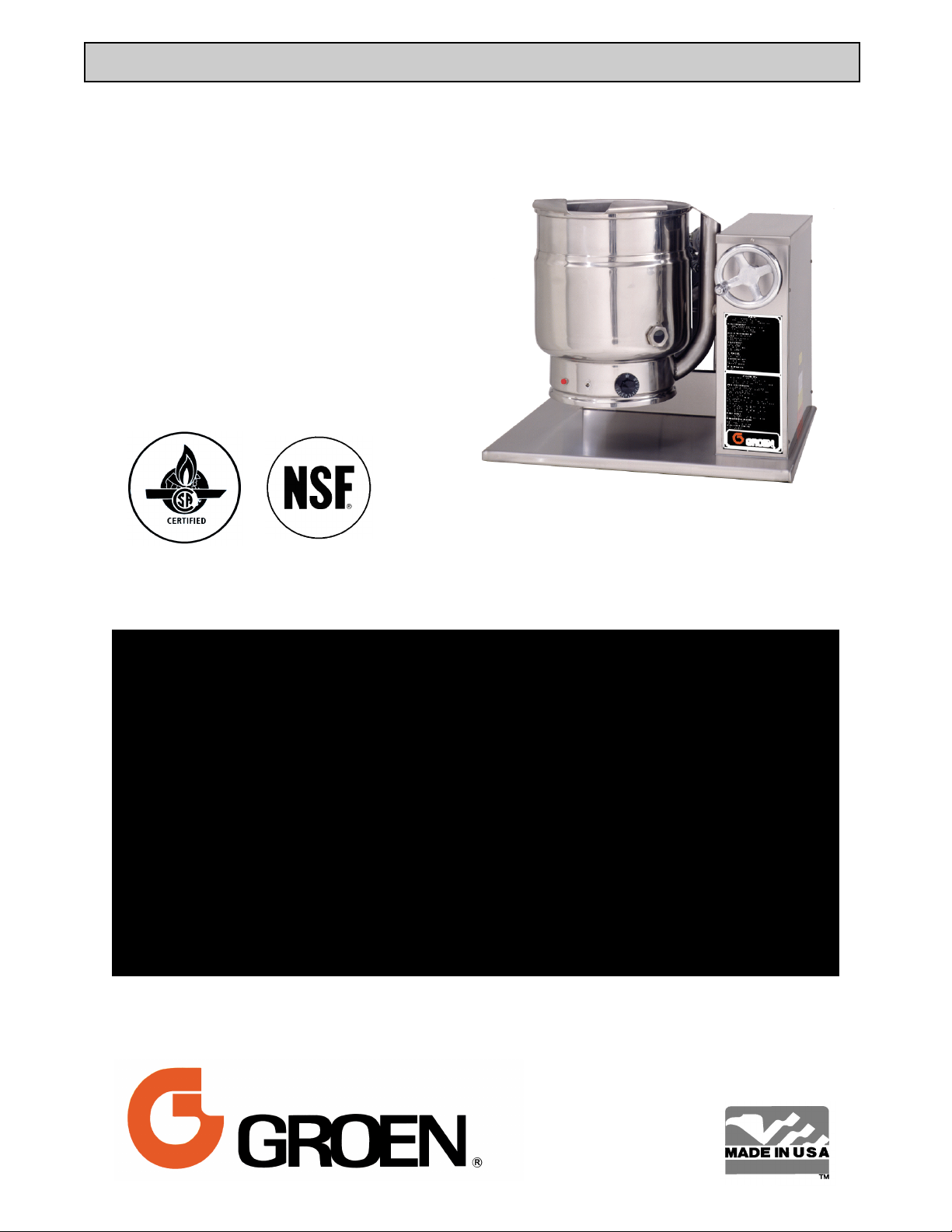
Model: TDH/C
Steam Jacketed Kettle
Self-contained
Gas heated
Table Top Mounted
Crank-Tilting
THIS MANUAL MUST BE RETAINED FOR FUTURE REFERENCE. READ,
UNDERSTAND AND FOLLOW THE INSTRUCTIONS AND WARNINGS CONTAINED IN
THIS MANUAL.
FOR YOUR SAFETY
DO NOT STORE OR USE GASOLINE OR OTHER FLAMMABLE VAPORS AND
LIQUIDS IN THE VICINITY OF THIS OR ANY OTHER APPLIANCE.
POST IN A PROMINENT LOCATION
INSTRUCTIONS TO BE FOLLOWED IN THE EVENT USER SMELLS GAS. THIS
INFORMATION SHALL BE OBTAINED BY CONSULTING YOUR LOCAL GAS
SUPPLIER. AS A MINIMUM, TURN OFF THE GAS AND CALL YOUR GAS COMPANY
AND YOUR AUTHORIZED SERVICE AGENT. EVACUATE ALL PERSONNEL FROM
THE AREA.
WARNING
IMPROPER INSTALLATION, ADJUSTMENT, ALTERATION, SERVICE OR
MAINTENANCE CAN CAUSE PROPERTY DAMAGE, INJURY OR DEATH. READ THE
INSTALLATION, OPERATING AND MAINTENANCE INSTRUCTIONS THOROUGHLY
BEFORE INSTALLING OR SERVICING THIS EQUIPMENT.
Page 2

OM/SM-TDH/C
IMPORTANT — READ FIRST — IMPORTANT
WARNING: FAILURE TO DISCONNECT POWER BEFORE SERVICING COULD RESULT IN
ELECTROCUTION AND DEATH.
WARNING: IMPROPER INSTALLATION, ADJUSTMENT, ALTERATION, SERVICE OR MAINTENANCE CAN
CAUSE PROPERTY DAMAGE, INJURY OR DEATH. READ THE INSTALLATION, OPERATING
AND MAINTENANCE INSTRUCTIONS THOROUGHLY BEFORE INSTALLING OR SERVICING
THIS EQUIPMENT.
WARNING: THE UNIT MUST BE INSTALLED BY PERSONNEL QUALIFIED TO WORK WITH ELECTRICITY
AND PLUMBING. UNIT MUST BE INSTALLED IN ACCORDANCE WITH ALL APPLICABLE
CODES.
WARNING: DO NOT ATTACH THE UNIT TO A TYPE “B” VENT. IT COULD CAUSE FIRE OR PROPERTY
DAMAGE.
WARNING: DO NOT CONNECT ANY PIPING TO THE SAFETY VALVE. IT MUST BE FREE TO VENT
STEAM AS NEEDED. TO AVOID BURNS FROM THE VENTED STEAM THE VALVE
DISCHARGE SHOULD POINT DOWNWARD.
DANGER: ELECTRICALLY GROUND THE UNIT AT THE TERMINAL PROVIDED. FAILURE TO GROUND
THE UNIT COULD RESULT IN ELECTROCUTION AND DEATH.
CAUTION: BE SURE ALL OPERATORS READ, UNDERSTAND AND FOLLOW THE OPERATING
INSTRUCTIONS, CAUTIONS AND SAFETY INSTRUCTIONS CONTAINED IN THIS MANUAL.
CAUTION: DO NOT OVERFILL THE KETTLE WHEN COOKING, HOLDING OR CLEANING. KEEP
LIQUIDS A MINIMUM OF 2-3" (5-8 CM) BELOW THE KETTLE BODY RIM TO ALLOW
CLEARANCE FOR STIRRING, BOILING AND SAFE TRANSFER OF PRODUCT.
CAUTION: KEEP FLOORS IN FRONT OF KETTLE WORK AREA CLEAN AND DRY. IF SPILLS OCCUR,
CLEAN IMMEDIATELY TO AVOID SLIPS OR FALLS.
WARNING: KEEP WATER AND SOLUTIONS OUT OF CONTROLS AND BURNERS. NEVER SPRAY OR
HOSE DOWN THE CONTROL CONSOLE, ELECTRICAL CONNECTIONS, ETC.
CAUTION: MOST CLEANERS ARE HARMFUL TO THE SKIN, EYES, MUCOUS MEMBRANES AND
CLOTHING. TAKE PRECAUTIONS: WEAR RUBBER GLOVES, GOGGLES OR FACE SHIELD
AND PROTECTIVE CLOTHING. CAREFULLY READ WARNINGS AND FOLLOW DIRECTIONS
ON CLEANER LABELS .
WARNING: DO NOT STAND ON OR APPLY UNNECESSARY WEIGHT OR PRESSURE ON THE KETTLE
FRONT OR POURING LIP. THIS COULD RESULT IN THE OVERLOAD AND FAILURE OF THE
TILT MECHANISM, AND POSSIBLE SERIOUS INJURY AND BURNS TO THE OPERATOR AND
OTHERS.
NOTICE: NEVER LEAVE A SANITIZER IN CONTACT WITH STAINLESS STEEL SURFACES LONGER
THAN 10 MINUTES. LONGER CONTACT CAN CAUSE CORROSION.
WARNING: FAILURE TO PERIODICALLY CHECK SAFETY VALVE OPERATION COULD RESULT IN
PERSONAL INJURY AND/OR DAMAGE TO EQUIPMENT.
WARNING: WHEN TESTING, AVOID EXPOSURE TO THE STEAM BLOWING OUT OF THE SAFETY
VALVE. DIRECT CONTACT COULD RESULT IN SEVERE BURNS.
WARNING: TO AVOID INJURY, READ AND FOLLOW ALL PRECAUTIONS STATED ON THE LABEL OF
THE WATER TREATMENT COMPOUND.
WARNING: BEFORE REPLACING ANY PARTS, DISCONNECT THE UNIT FROM THE ELECTRIC POWER
SUPPLY AND CLOSE THE MAIN GAS VALVE. ALLOW FIVE MINUTES FOR GAS TO VENT.
CAUTION: USE OF ANY REPLACEMENT PARTS OTHER THAN THOSE SUPPLIED BY GROEN OR
AUTHORIZED DISTRIBUTORS CAN CAUSE INJURY TO THE OPERATOR AND DAMAGE TO
THE EQUIPMENT AND WILL VOID ALL WARRANTIES.
WARNING: KEEP AREA AROUND KETTLE FREE AND CLEAR OF ALL COMBUSTIBLE MATERIALS.
FAILURE TO DO SO COULD RESULT IN FIRE OR PROPERTY DAMAGE.
CAUTION: HEATING AN EMPTY KETTLE MAY CAUSE THE RELEASE OF STEAM FROM THE SAFETY
VALVE.
Important: Service Performed by Other than Factory Authorized Personnel Will Void All Warranties.
2
Page 3

OM/SM-TDH/C
Table of Contents
IMPORTANT OPERATOR WARNINGS .........................................2
EQUIPMENT DESCRIPTION ..................................................4
INSPECTION & UNPACKING .................................................5
INSTALLATION & INITIAL START-UP ..........................................6
OPERATION ..............................................................8
CLEANING ...............................................................11
MAINTENANCE ...........................................................12
SEQUENCE OF OPERATION ................................................14
TROUBLESHOOTING .....................................................14
PARTS LISTS .............................................................16
SCHEMATIC .............................................................20
SERVICE LOG ............................................................21
REFERENCES ............................................................22
WARRANTY ..............................................................23
3
Page 4
OM/SM-TDH/C
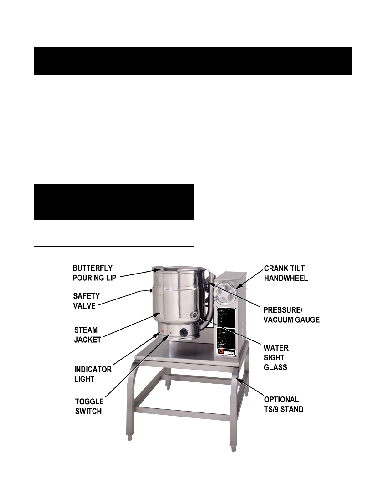
Equipment Description
Groen Model TDH/C is a stainless steel, steamjacketed, table top mounted, crank-tilting kettle with
a self-contained, gas heated steam source. The
kettle body is welded into one solid piece and
furnished with a reinforced rim and welded-in
"butterfly" shaped pouring lip. The interior of the
kettle is polished to a 180 emery grit finish, and the
exterior is given a bright high buff finish. The unit is
A.S.M.E. shop inspected and registered with the
National Board for working pressures up to 50 PSI.
The self-contained steam source is heated by
propane, butane, or natural gas and is equipped with
electronic ignition. Charged at the factory with
chemically pure water containing rust inhibitors, the
steam source provides kettle temperatures of 150ºF
to approximately 295oF.
KETTLE CHARACTERISTICS
Dimensions
Model
Kettle
Capacity
Jacket
Capacity
Kettle Body
Diameter
Controls for the unit include a crank tilt handwheel,
thermostat, pressure gauge, safety valve, low water
cut-off, On/Off switch, gas regulator valve, and water
level sight glass.
The gas supply shuts off automatically when the
kettle is tilted.
The unit must be specified for use with natural gas,
propane, butane, or a stated propane/butane
mixture. Service connections are required for gas
and 115V electricity.
Firing Rate, BTU / Hour
TDH/C-20 TDH/C-40
31,000 BTU/hr 52,000 BTU/hr
Kettle Body
Depth
Base Width Base Depth
TDH/C-20 20 Qt 18.9 R 6 Qt 5.7 R 14" 356 mm 11" 279 mm 28" 711 mm 24" 610 mm
TDH/C-40 40 Qt. 37.8 R 8 Qt 7.6 R 16½ 419 mm 14½” 362 mm 28" 711 mm 26¾” 679 mm
Options available include:
1. One-piece, lift-off cover.
2. Basket insert.
3. Stand that supports the unit and holds a pan
in position for filling.
4. Water fill swing faucet.
5. Mirror Image (Crank on the Left)
6. 316 stainless steel interior
4
Page 5
OM/SM-TDH/C
Inspection & Unpacking
WARNING
THIS UNIT MUST BE INSTALLED BY PERSONNEL WHO ARE QUALIFIED TO WORK WITH ELECTRICITY
AND PLUMBING. IMPROPER INSTALLATION CAN CAUSE INJURY TO PERSONNEL AND/OR DAMAGE TO
THE EQUIPMENT. THE UNIT MUST BE INSTALLED IN ACCORDANCE WITH APPLICABLE CODES.
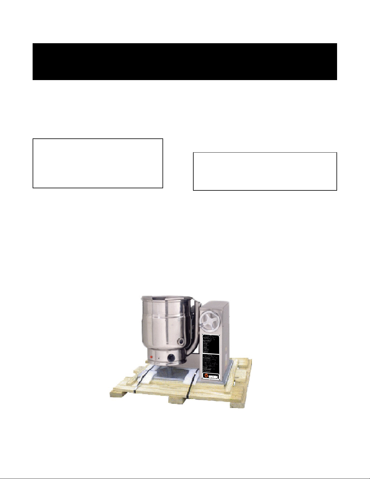
The unit arrives completely assembled. The unit is
strapped on a skid and in a heavy carton. Inspect
the carton carefully for damage. Open the container
and check the unit for hidden damage. Report
shipping damage or shipment errors to the delivery
agent.
CAUTION
SHIPPING STRAPS ARE UNDER TENSION
AND CAN SNAP BACK WHEN CUT. TAKE
CARE TO AVOID PERSONAL INJURY OR
DAMAGE TO THE UNIT BY STAPLES LEFT
IN THE WALLS OF THE CARTON.
Write down the model number, serial number, and
installation date for your unit at the top of the
Maintenance and Service Log on Page 21. Keep this
manual with the unit.
To remove the kettle from the box, cut any straps from
around the box. Detach the box sides from the skid.
Pull the box up off the unit, taking care to avoid damage
or injury from any staples left in the box walls. When
installation is to begin, cut the straps holding the kettle
on the skid, and lift the kettle straight up off the skid.
Examine the packing materials to make sure no loose
parts are discarded with the materials.
CAUTION
UNIT WEIGHS FROM 215 LBS. (98 KG) TO 240
LBS. (109 KG). INSTALLER SHOULD OBTAIN
HELP AS NEEDED TO LIFT THIS WEIGHT
SAFELY.
When installation is to begin, carefully cut the straps
which hold the unit on the skid. Lift the unit straight up
off the skid. Examine packing materials to be sure
loose parts are not discarded with the materials.
The TDH/C is shipped from the factory strapped on a
pallet.
5
Page 6

OM/SM-TDH/C
WARNING
THE KETTLE MUST BE INSTALLED BY PERSONNEL QUALIFIED TO WORK WITH ELECTRICITY AND
PLUMBING. IMPROPER INSTALLATION CAN CAUSE INJURY TO PERSONNEL AND/OR DAMAGE TO THE
EQUIPMENT.
Installation and Initial Start-Up
A. Installation
The TDH/C kettle should be installed in a ventilated room
for efficient performance. Items which might obstruct or
restrict the flow of air for combustion and ventilation must
be removed. The area directly around the appliance
must be cleared of any combustible material.
1. Installation on combustible floors is allowed. The
unit requires a minimum clearance to combustible
and noncombustible construction of six inches at the
rear and six inches at the sides.
2. Groen recommends installation of the unit under a
vent hood. The base must be fastened to the
working surface.
3. Complete the piping to the gas service main using ½
inch IPS pipe or an approved equivalent.
WARNING
THIS UNIT IS FOR COMMERCIAL USE. DO NOT
USE HOME OR RESIDENTIAL GRADE GAS
CONNECTIONS. THEY DO NOT MEET GAS CODES
AND COULD BE HAZARDOUS.
4. Provide 115 VAC, 60 cycle, 1 phase, 1 AMP electric
service. Local codes and/or The National Electrical
Code should be observed in accordance with
ANSI/NFPA-70 latest edition. AN ELECTRICAL
GROUND IS REQUIRED. The electrical schematic
is located on the inside of the service panel, and at
the rear of this manual. In Canada provide electric
service in accordance with the Canadian Electrical
Code, C.S.A.-C22.1 Part 1 and/or local codes.
at test pressures that exceed ½ PSIG (3.45
kPa). The kettle must be isolated from the gas
supply piping system by closing its individual
manual shutoff valve during any pressure testing
of that system at test pressures which equal or
are less than ½ PSIG (3.45 kPa).
7. Adequate space for proper servicing and
operation is required. DO NOT block any air
intake spacings to the combustion chamber or
obstruct air flow.
8. After the kettle has been connected to the gas
supply, check all gas joints for leaks. A thick
soap solution or other suitable leak detector
should be used. Do not use flame when
checking the leaks.
9. Once the unit is anchored to a mounting surface,
Apply a small bead of silicone caulk around the
perimeter of the kettle base.
10. Make sure the water level is correct in the jacket,
by confirming that the level is near the middle of
the sight glass. If the water level is low, follow
the instructions in Jacket Filling and Water
Treatment in the Maintenance section of this
manual.
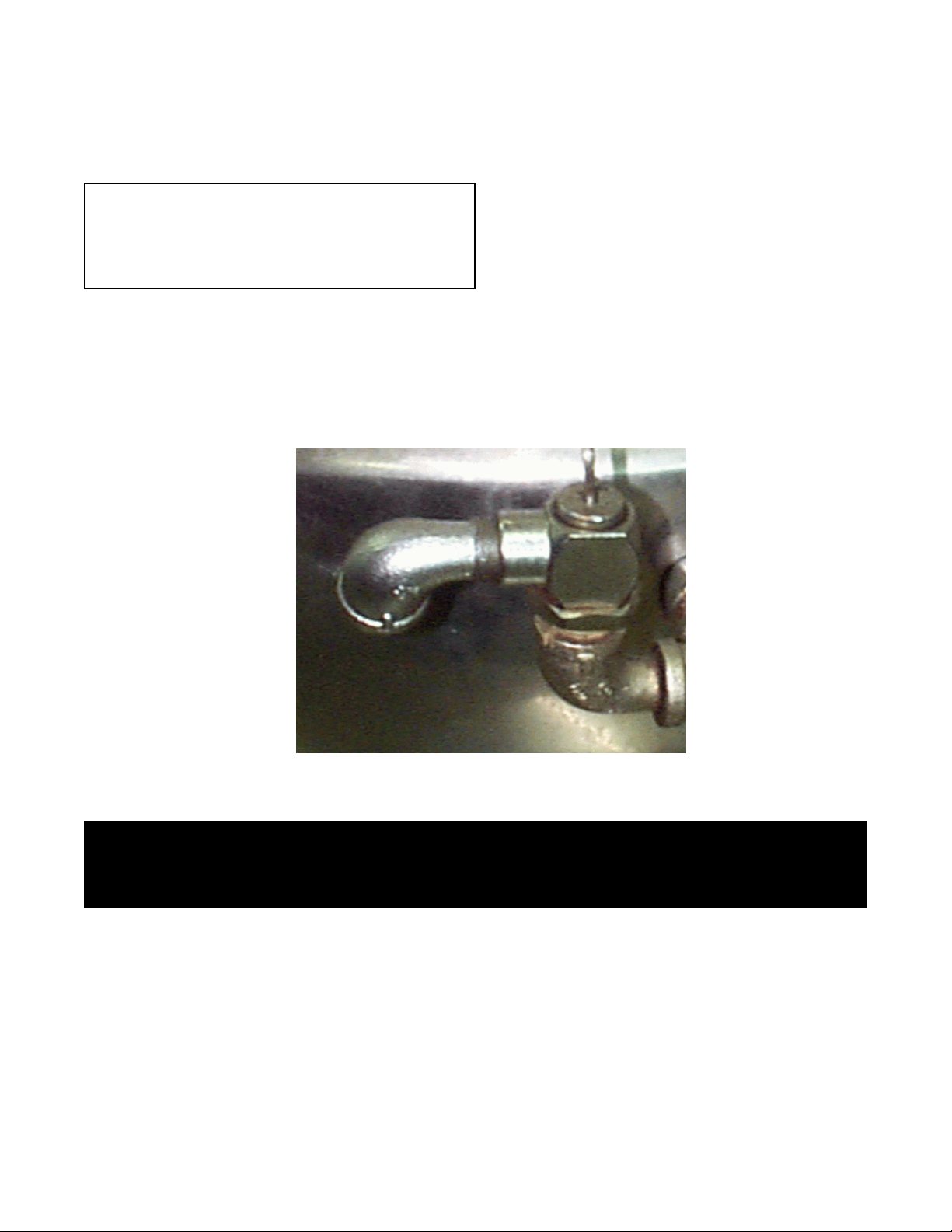
11. Check to be sure that the open end of the elbow
5. The installation must conform with local codes or the
American National Standards Z223.1 - latest edition
National Fuel Gas Code. The kettle should be
installed in an adequately ventilated room with
provision for adequate air supply. the best ventilation
will employ a vent hood and exhaust fan with no
direct connection between the vent duct and the
kettle flue. DO NOT obstruct the flue or vent duct
after installation. In Canada, the installation must
conform to CAN/CGA B149 Installation Codes for
Gas Burning Appliances and Equipment and/or local
codes.
6. The appliance and its individual shutoff valve must
be disconnected from the gas supply piping system
during any pressure testing of the gas supply system
Correct water level
6
Page 7
OM/SM-TDH/C
on the outlet of the safety valve is directed
downward. Be sure to read and follow the
instructions on the attached safety valve tag.
B. Initial Start-Up
IMPORTANT:
BE SURE ALL OPERATORS READ, UNDERSTAND
AND FOLLOW THE OPERATING INSTRUCTIONS,
CAUTIONS, AND SAFETY INSTRUCTIONS
CONTAINED IN THIS MANUAL.
After the kettle has been installed, the installer should
test to ensure that it is operating correctly.
1. Remove literature and packing materials from inside
and outside of the unit.
2. Put on or two inches of water into the kettle.
3. Make sure the supplies of gas and electric power
are on.
4. Follow the “To Start Kettle Heating” instructions
in the Operation section of this manual. Begin
heating the water at the highest thermostat
setting. The indicator light should come on and
heating should continue until the water boils.
5. To turn off the unit, follow “To Stop Kettle
Heating” in the Operation Section of this manul..
If the kettle functions as described, it is ready for
use. If the unit does not operate as designed,
contact authorized Groen Service Agent.
Make sure that the open end of the elbow on the
pressure safety valve is directed downward.
WARNING
DO NOT STAND ON OR APPLY UNNECESSARY WEIGHT OR PRESSURE ON THE KETTLE FRONT OR
POURING LIP. THIS COULD RESULT IN THE OVERLOAD AND FAILURE OF THE TILT MECHANISM, AND
POSSIBLE SERIOUS INJURY AND BURNS TO THE OPERATOR AND OTHERS.
7
Page 8
OM/SM-TDH/C
Operation
WARNING
ANY POTENTIAL USER OF THE EQUIPMENT MUST BE TRAINED IN SAFE AND CORRECT OPERATING
PROCEDURES
A. Controls
Operator controls for the TDH/C kettle are:
1. Manual gas valve which controls the supply of gas
from the main to the unit.
2. On-Off (toggle) switch. This switch turns the control
circuit power supply on or off.
3. Thermostat dial, which turns the thermostat on or off,
and sets the kettle operating temperature.
4. Crank tilt handwheel which controls kettle movement.
B. Operating Instructions
WARNING
KEEP AREA AROUND KETTLE FREE AND CLEAR OF
ALL COMBUSTIBLE MATERIALS. .DO NOT ATTEMPT
TO LIGHT ANY BURNER WITH A FLAME.
CAUTION
HEATING AN EMPTY KETTLE MAY CAUSE THE
RELEASE OF STEAM FROM THE SAFETY VALVE.
1. To Start Kettle
a. CHECK THE WATER LEVEL IN THE
JACKET EVERY DAY. The level should be
at the middle of the sight glass. If the water
level is low, see Jacket Filling in the
Maintenance section of this manual.
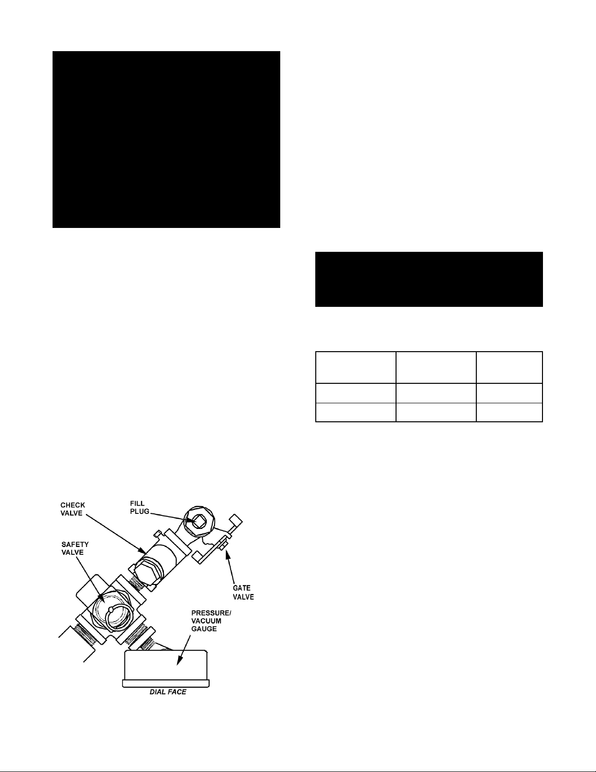
b. Check the pressure/vacuum gauge. If the
gauge does not show 20 to 30 inches of
vacuum (i.e. a reading of 20 to 30 below
zero), see Jacket Vacuum in the
Maintenance section of this manual.
c. DO NOT attempt to light any burner with a
flame.
d. Open the main supply gas valve (handle in
line with the pipe).
e. Turn the toggle switch to ON.
f. Turn the thermostat to the desired setting.
The TDH/C is shown on the optional TS/9 stand.
8
Page 9

OM/SM-TDH/C
2. To Stop Kettle Heating
a. Turn the thermostat dial to OFF.
b. Turn the toggle switch OFF.
c. For a prolonged shut-down:
1. Follow the procedure above.
2. Turn the manual gas valve OFF (handle at
right angle to gas line).
3. Disconnect the unit’s electrical power.
3. To Relight Kettle
a Close main gas supply valve.
b. Set on-off switch to OFF.
c. Set thermostat to OFF.
d. Wait five minutes, then proceed as directed under
To Start Kettle.
4. If Electric Power Fails, do not attempt to operate
the unit. When power is restored, proceed as
directed in To Start Kettle.
5. To Transfer Product or Empty Kettle:
The kettle body is tilted using the crank tilt handwheel.
Turning the crank clockwise tilts the kettle body;
counter-clockwise returns it to an upright position. The
kettle body will remain in any tilted position.
CAUTION
DO NOT OVERFILL THE KETTLE WHEN
COOKING, HOLDING OR CLEANING. KEEP
LIQUIDS 2-3” (5-8 cm) BELOW THE KETTLE
RIM TO ALLOW CLEARANCE FOR STIRRING,
BOILING PRODUCT AND SAFE TRANSFER.
WARNING
WHEN TILTING KETTLE:
1) WEAR PROTECTIVE OVEN MITT AND
PROTECTIVE APRON.
2) USE DEEP CONTAINER TO CONTAIN AND
MINIMIZE PRODUCT SPLASHING.
3) PLACE CONTAINER ON STABLE, FLAT
SURFACE, CLOSE TO THE KETTLE.
4) STAND TO AWAY FROM POUR PATH OF
HOT CONTENTS.
5) POUR SLOWLY, KEEP CONTROL OF
KETTLE, AND RETURN KETTLE BODY
SLOWLY TO UPRIGHT POSITION AFTER
CONTAINER IS FILLED OR TRANSFER IS
COMPLETE.
6) DO NOT OVERFILL CONTAINER. AVOID
DIRECT SKIN CONTACT WITH HOT
CONTAINER AND ITS CONTENTS.
6. Use of Common Accessories
1. Lift-Off Cover
a. As with stock pot cooking, an optional lift off
cover will speed up the heating of water and
food products. A cover helps retain heat in
the cooking vessel and reduces the amount
of heat and humidity released into the
kitchen. Use of a cover can reduce some
product cook times and help maintain the
temperature, color and texture of products
being held or simmered for extended
periods.
WARNING
AVOID ALL DIRECT CONTACT WITH HOT FOOD OR
WATER IN THE KETTLE. DIRECT CONTACT COULD
RESULT IN SEVERE BURNS.
TAKE CARE TO AVOID CONTACT WITH HOT KETTLE
BODY OR HOT PRODUCT, WHEN ADDING
INGREDIENTS, STIRRING OR TRANSFERRING
PRODUCT TO ANOTHER CONTAINER.
b. Make sure the plastic ball handle is secure
on the lift off cover before using. ALWAYS
use the plastic handle to place or remove
cover from the kettle. Wear protective oven
mitts and a protective apron.
c. When putting the cover on the kettle,
position it on top of kettle rim, with its flat
edge facing the pouring lip.
d. When removing cover:
1) Firmly grasp plastic handle
9
Page 10

OM/SM-TDH/C
WARNING
AVOID ALL DIRECT CONTACT WITH HOT
SURFACES. DIRECT SKIN CONTACT COULD
RESULT IN SEVERE BURNS.
AVOID ALL DIRECT CONTACT WITH HOT FOOD OR
WATER IN THE KETTLE. DIRECT CONTACT COULD
RESULT IN SEVERE BURNS.
CAUTION
DO NOT TILT KETTLE BODY WITH COVER OR
BASKET INSERT IN PLACE. COVER MAY SLIDE
OFF, CAUSING INJURY TO OPERATOR.
2. Basket Insert
a. An optional kettle basket insert can assist in
cooking water-boiled products including
eggs, potatoes, vegetables, shell fish, pasta
and rice. The nylon mesh liner must be
used when cooking product smaller than the
mesh size of the basket, which is
approximately 1/4” (6 mm). This includes
rice and small pasta shapes.
b. Tips For Use.
1) Allow for the water displacement of the
basket and product to be cooked. This
may mean only filling the kettle half full
of water. Test the basket and product
displacement with the kettle OFF, and
with cold water in the kettle.
2) Lift rear edge (farthest from operator) 1-2” (35 cm) to allow any steam and water vapor to
escape the cooking vessel. Wait 2-3 seconds.
Lift the rear edge of the lid first.
3) Tilt cover to 45-60° angle and allow any hot
condensate or product to roll off cover back
into kettle.
4) Remove cover, ensuring that any remaining
hot condensate or product does not drip on
operator, floor or work surfaces.
5) Place cover on safe, flat, sanitary, out-of-theway surface, or return to kettle rim.
CAUTION
DO NOT OVERFILL THE KETTLE WHEN
COOKING, HOLDING OR CLEANING. KEEP
LIQUIDS A MINIMUM OF 2-3” (5-8 cm) BELOW
THE RIM TO ALLOW FOR STIRRING, BOILING
AND SAFE PRODUCT TRANSFER.
2) Load basket on a level, stable work
surface.
3) Lift the loaded basket with both hands.
Get help from another person if the
basket is too heavy for safe handling.
Then slowly lower product into kettle.
4) When removing basket with cooked
product, lift basket straight up, ensuring
bottom of basket clears the rim and
pouring lip of the kettle. Wear protective
oven mitts and protective apron.
5) Allow hot water to fully drain from
product, before moving basket away
from the kettle. Do not rest kettle
basket on kettle rim or pouring lip. If
basket is too heavy for individual to lift
and safely move, get help from another
person. Remove product immediately
from basket into another container,
being sure to avoid contact with hot
product and hot basket or place basket
with food on stable, flat surface, setting
it inside a solid steamer or bake pan, to
catch any remaining hot water draining
from product.
10
Page 11

1. Suggested Cleaning Supplies:
a. Cleaner, such as Klenzade HC-10 or HC-32
from ECOLAB, Inc.
b. Kettle brushes in good condition.
c. Sanitizer such as Klenzade XY-12.
OM/SM-TDH/C
Cleaning
d. Film remover such as Klenzade LC
2. Precautions
Before any cleaning operation, shut off the kettle
by turning the thermostat dial to "OFF".
WARNING
KEEP WATER AND SOLUTIONS OUT OF
CONTROLS AND BURNERS. NEVER SPRAY OR
HOSE THE CONTROL CONSOLE, ELECTRICAL
CONNECTIONS, ETC.
3. Procedure
a. Clean food contact surfaces as soon as
possible after use, preferably while the kettle
is still warm. If the unit is in continuous use,
clean and sanitize inside and outside at least
once every 24 hours.
b. Scrape and flush out large amounts of food
residues. Be careful not to scratch the kettle
with metal implements.
CAUTION
NEVER LEAVE A CHLORINE SANITIZER IN
CONTACT WITH STAINLESS STEEL SURFACES
LONGER THAN 30 MINUTES. LONGER CONTACT
CAN CAUSE CORROSION.
CAUTION
MOST CLEANERS ARE HARMFUL TO THE SKIN,
EYES, MUCOUS MEMBRANES AND CLOTHING.
PRECAUTIONS SHOULD BE TAKEN TO WEAR
RUBBER GLOVES, GOGGLES OR FACE SHIELD
AND PROTECTIVE CLOTHING. CAREFULLY READ
THE WARNINGS AND FOLLOW LABEL
DIRECTIONS.
e. As part of the daily cleaning program, clean
all inside and outside surfaces that may have
been soiled. Remember to check such parts
as the underside of the cover, control
housing, etc.
f. To remove materials stuck to the equipment,
use a brush, sponge, cloth, plastic or rubber
scraper, or plastic wool along with the
detergent solution. To make washing easier,
let the detergent solution sit in the kettle and
soak into the residue, or warm the detergent
solution briefly. Do not use any metal
material (like metal sponges) or metal (like a
spoon, scraper, or wire brush) that might
scratch the surface. Scratches make the
surface hard to clean and provide places for
bacteria to grow. Do not use steel wool,
which may leave particles imbedded in the
surface and cause eventual corrosion and
pitting.
c. Prepare a solution of the detergent/cleaning
compound as instructed by the supplier.
Clean the unit thoroughly. A cloth moistened
with cleaning solution can be used to clean
controls, housing, electrical conduit, etc.
d. Rinse the kettle thoroughly with hot water.
Then drain completely.
Use a sponge, cloth or plastic brush to clean
the kettle.
11
Page 12

OM/SM-TDH/C
I. Following the supplier’s instructions, apply the
sanitizing agent, after the unit has been
cleaned and drained. Rinse off the sanitizer
thoroughly.
j. It is recommended that the unit be sanitized
just before use.
k. If there is difficulty removing mineral deposits
or a film left by hard water or food residues,
clean the kettle thoroughly. Then use a deliming agent, such as Groen De-limer DeScaler (Part Number 114800), Lime- Away
from ECOLAB or an equivalent, following
manufacturer directions.
Scrapers, steel wool or metal implements can
harm the kettle surface.
g. The outside of the unit may be polished with
a recognized stainless steel cleaner like
“Zepper” from Zep Manufacturing Company.
h. When the equipment needs to be sanitized,
use a sanitizing solution equivalent to one
that supplies 200 parts per million chlorine.
Obtain advice on the best sanitizing agent
from your supplier of sanitizing products.
Maintenance
NOTICE: Contact Groen or an authorized Groen Service Agent when repairs are required.
Service Log is provided at the rear of this manual.
Each time service is performed on this Groen
equipment, enter the date on which the work was
done, and who did it. Keep this manual with the
equipment.
1. Jacket Vacuum/Removing Air From Jacket
Every day, while the kettle is cold, read the pressure/
vacuum gauge. A positive reading or a negative
reading between zero and 20 on the pressure/
vacuum gauge indicates excess air in the jacket. Air
in the jacket slows kettle heating and can prevent the
kettle from reaching operating temperature. To
remove air:
a. Start the kettle. (See the “Operation”
section).
l. Rinse and drain the unit thoroughly before
further use.
m. If especially difficult cleaning problems
persist, contact your cleaning product
supplier for assistance. The supplier has a
trained technical staff with laboratory facilities
to serve you.
lever for about one second. Repeat this
step, then let the valve lever snap closed,
so the valve will seat properly and not leak.
2. Test Safety Valve
At least twice a month, test the safety valve.
Test the valve with the kettle operating at 15
PSI (105 kPa), by holding the test lever for at
least five seconds. Then release the lever and
permit the valve to snap shut. If the lever does
not activate, if there is no discharge, or if the
valve leaks, stop using the kettle immediately
and contact a qualified factory service
representative.
b. Make sure the elbow on the outlet of the
safety valve is turned so that escaping
steam is directed down toward the floor.
c. When the pressure/vacuum gauge reaches
a positive pressure reading of five PSI,
release trapped air by lifting the safety valve
12
Page 13
OM/SM-TDH/C
WARNING
AVOID ANY EXPOSURE TO THE STEAM
BLOWING OUT OF THE SAFETY VALVE.
SEVERE BURNS CAN RESULT ON EXPOSED
SKIN.
FAILURE TO CHECK SAFETY VALVE
OPERATION PERIODICALLY COULD RESULT IN
PERSONAL INJURY AND/OR DAMAGE TO
EQUIPMENT.
WHEN TESTING, AVOID ANY EXPOSURE TO
THE STEAM BLOWING OUT OF THE SAFETY
VALVE. DIRECT CONTACT COULD RESULT IN
SEVERE BURNS.
3. Jacket Filling
Every day, before you turn on the unit, make
sure the water level is approximately in the
center of the water gauge glass. The jacket
was filled at the factory with the proper amount
of treated water, and is air-tight, but over time
steam may be vented and water lost.
assembly. Then open the gate valve and
pour in the distilled or treated water. Using
a funnel will help you in this process. Hold
the safety valve open while you pour, to let
air escape from the jacket. Continue adding
water until the water level rises to the
center of the round sight glass.
c. Close the gate valve.
d. Air that gets into the jacket during the filling
operation must be removed, because it will
make heating less efficient. Follow the
procedure in “Jacket Vacuum” above, to
restore a negative pressure reading.
4. Water Treatment
WARNING
TO AVOID INJURY, READ AND FOLLOW ALL
PRECAUTIONS STATED ON THE LABEL OF THE
WATER TREATMENT COMPOUND.
a. Fill a mixing container with the amount of
water required. Use only distilled water.
From time to time, you may need to restore the
water to its proper level. The procedure for
adding water follows.
a. If you are replacing water lost as steam,
use distilled water. Do not use tap water.
If you are replacing treated water that was
drained from the jacket, prepare more
treated water as directed below.
b. Allow the kettle to cool completely.
Remove the pipe plug from the jacket fill
Model
TDH/C-20 20 Qts 18.9 R 6 Qts 5.7 R
TDH/C-40 40 Qts 37.8 R 8 Qts 7.6 R
b. Hang a strip of pH test paper on the rim of
the container, with about 1 inch of the strip
below the surface of the water.
c, Stir the water continuously, while you slowly
add water treatment compound until a color
between indicating a pH of 10.5 and 11.5 is
reached. (Shown on the pH test kit chart.)
Judge the pH by frequently comparing the
test strip with the color chart provided in the
pH test kit.
d. Use a measuring cup to add the compound
so that you may record the exact amount
used.
e. The amount may be used again, if the
same water sources and compound are
used in the future. However, it is best to
check the pH each time treated water is
prepared.
Kettle
Capacity
Jacket
Capacity
The safety valve and fill plug are located directly
behind the pressure/vacuum gauge.
13
Page 14

OM/SM-TDH/C
Sequence of Operation
The following “action-reaction” outline is provided to
help the user understand how the equipment works.
When the operator sets the desired temperature on
the thermostat dial, the thermostat switch closes and
sends a signal which (1) starts the spark and (2)
opens the automatic valve for the pilot burner. The
spark ignites the pilot flame, which heats a probe.
The heated probe sends a signal that causes the
spark to shut off and the automatic valve to admit
gas to the main burner. The pilot flame ignites the
main burner. If a pilot flame is not sensed within 30
seconds after the spark begins, a timer shuts down
the whole operation. In addition to the lockout timer,
safety features include:
1. Low water cutoff relay that will shut off the
gas supply to all burners until the water
level is corrected.
2. High limit pressure switch, set to open at
about 47 PSI and shut down the burners
until jacket pressure is decreased.
3. Pop safety valve, which will release steam if
the jacket pressure exceeds 50 PSI.
4. Tilt switch that shuts off all burners when
the kettle is tilted.
When the kettle reaches the set temperature, the
thermostat switch opens, stopping the signal to the
gas control valve and causing the valve to shut off all
gas flow. When the kettle cools below the set
temperature, the thermostat switch closes and starts
another heating cycle. On-off cycling continues and
maintains the kettle at the desired temperature.
Troubleshooting
Your Groen kettle is designed to operate smoothly and efficiently if properly maintained. However, the following is
a list of checks to make in the event of a problem. Wiring diagrams are furnished inside the service panel and in
this manual. If an item on the list is followed by X, the work should be done by a qualified service
representative.
WARNING
BEFORE REPLACING ANY PARTS, DISCONNECT THE UNIT FROM THE ELECTRIC POWER SUPPLY
AND CLOSE THE MAIN GAS VALVE. ALLOW FIVE MINUTES FOR UNBURNED GAS TO VENT.
CAUTION
USE OF ANY REPLACEMENT PARTS OTHER THAN THOSE SUPPLIED BY GROEN OR THEIR AUTHORIZED
DISTRIBUTOR CAN CAUSE INJURY TO THE OPERATOR AND DAMAGE TO THE EQUIPMENT AND WILL
VOID ALL WARRANTIES..
SYMPTOM WHO WHAT TO CHECK
X indicates items which must be performed by an authorized technician.
Kettle is hard to tilt. Auth
Service
Rep Only
Kettle continues heating after
it reaches desired
temperature.
Kettle stops heating before it
reaches the desired
temperature.
Safety Valve pops open User a. For air in the jacket. See “Jacket Vacuum” in the Maintenance
Safety Valve pops open Auth
User a. Thermostat dial setting.
Auth
Service
Rep Only
User a. Thermostat dial setting.
Auth
Service
Rep Only
Service
Rep Only
a. Gears for foreign materials, lubrication and alignment. X
b. Thermostat calibration. X
c. Thermostat operation. The thermostat should click when the dial is
rotated to settings above and below the temperature of the kettle. X
b. Thermostat calibration. X
c. Thermostat operation. The thermostat should click when the dial is
rotated to settings above and below the temperature of the kettle. X
section.
b. Thermostat dial setting.
c. For defective thermostat. The thermostat should click when dial is
rotated above and below kettle temperature. If defective, replace. X
d. For defective safety valve. If valve pops below 49 PSI, replace. X
14
Page 15

OM/SM-TDH/C
SYMPTOM WHO WHAT TO CHECK
X indicates items which must be performed by an authorized technician.
Burners will not light. User a. That main gas supply valve is open. (handle in line with gas pipe).
b. Gas supply to the building.
c. That the kettle body is horizontal.
System does not produce a
spark
Spark is present but the pilot
will not light.
Pilot lights, but main burner
will not come on and spark
does not stay on.
Pilot lights, but main burner
will not come on, the spark
stays on.
Auth
Service
Rep Only
Auth
Service
Rep Only
Auth
Service
Rep Only
Auth
Service
Rep Only
Auth
Service
Rep Only
d. Thermostat operation. The thermostat should click when the dial is
rotated to settings above and below the temperature of the kettle. X
e. Momentary switch is being properly actuated. X
a. Thermostat, and close the contacts if they are open X
b. AC voltage between terminals “2" and “GR.” If it is not 24 Volt,
replace the transformer X
c. That the jumper is securely installed between terminal “5" and “GR.”
d. That the high tension cable is firmly attached and in good condition.
If cracked or brittle, replace the pilot. X
e. Pilot electric ceramic for crack or break. X
f. Pilot spark gap. Regap, if it is not 7/64 inch. X
g. Replace the electronic portion of the G770 system. X
a. That the pilot valve is securely connected to terminals “1" and “GR.”
(Some models have the pilot valve grounded internally).X
b. For 24 VAC at terminals “1" and “GR.” If 24V is not present, replace
the G770 ignition control. X
b. That gas pressure meets the control manufacturer specifications. X
c. For gas at the pilot. If it is not flowing:
(1) Check the pilot gas line for kinks and obstructions. X
(2) Clean orifice, if necessary. X
(3) Replace the pilot valve. X
d. That the pilot spark gap is 7/64 inch and located in the pilot gas
stream. If not, adjust or replace the pilot. X
e. For drafts. Shield the pilot burner, if necessary. X
a. For 24 V between terminals “3" and “GR”. If voltage is not correct,
replace the G770 ignition control. X
b. That the gas pressure meets control manufacturer specifications. X
c. Electrical connections of main valve to terminals “3" and “GR” to
assure they are securely attached. If so, replace the main valve.” X
a. That sensor cable and high voltage cable are separated from each
other and not wrapped around any pipe or accessory. X
b. Sensor cable, to ensure that there are secure attachments to
terminal “4" and the sensor. X
c. Sensor ceramic for cracks. X
d. That cable is not grounded out. If it is, correct the ground. X
e. That the sensor or sensor connector is not grounded out. X
f. Sensor cable for continuity and condition of insulation. X
g. Disconnect main valve lead from terminal “3," and sensor cable
from terminal “4.” Observing correct polarity, connect a DC micro
ammeter between the sensor cable terminal and terminal “4.”
Check that the current is 0.15 microamp or greater with only the pilot
operating. If it is, replace the G770 ignition control. X
h. For proper gas pressure. X
i. Clean pilot assembly, if necessary. X
j. Tighten all mechanical and electrical connections. X
k. Pilot application, and correct to increase sensor probe current, by:
(1) Increasing or decreasing pilot orifice size. X
(2) Shielding the pilot from drafts. X
l. Replace sensor or orifice. X
m. Replace G770 ignition control. X
15
Page 16

OM/SM-TDH/C
Parts List
To order parts, contact your Groen Certified Service Agency. Supply the model designation, part description, part number, quantity, and, where applicable,
voltage and phase.
16
Page 17

OM/SM-TDH/C
Parts List
To order parts, contact your Groen Certified Service Agency. Supply the model designation, part description, part number, quantity, and, where applicable, voltage
and phase.
Key Description Part No. Key Description Part No. Key Description Part No.
1 Weldment, TDH-40 122376 25 Assembly, Electrical Panel - TDH 128034 48 Shroud, Burner TDH/C-20 097020
Weldment, TDH-20 124713 26 Weldment, Body 304 ss TDH-40 128024 49 Screw, 1/4-20 x 1/2 hex head ss 005608
2 Weldment, Base Support 124729 Weldment, Body 316 ss TDH-40 128045 50 Label, Wiring Diagram 132391
3 Screw, 1/4-20 x 1/2 truss head ss 012700 Weldment, Body 304 ss TDH-20 128030 51 Label, Warning 132398
4 Screw, 1/2-13 x 1-1/4 hex head ss 005623 Weldment, Body 316 ss TDH-20 128046 52 Grommet, 1-1/2 ID 003492
5 Nut hex 1/2-13 ss 005603 27 Lamp, Indicator, Red 003332 53 Bracket, Faucet 009054
6 Washer, lock 1/2 ss 005657 28 Elbow, 90 degrees street 003922 54 Screw, 1/4-20 x 1/2 Tr head ss 012700
7 Weldment, pedestal, TDH/C-40 124735 30 Assy, Safety Valve & Pressure Gauge 005801 55 Plate, Data 132316
Weldment, pedestal, TDH/C-20 124737 31 Sight Glass 005831 56 Label, NSF 066735
8 Weldment, Cladding Side, TDH/C-40 124748 32 Switch, On-Off 006904 57 Bushing, Snap 000453
Weldment, Cladding Side, TDH/C-20 124755 33 Thermostat 101524 58 Screw, 1/4-20 x 3/4 hex ss (TDH-40) 005609
9 Cladding, Panel TDH/C-40 124751 34 Nameplate, TDH 132390 Screw, 1/4-20 x 1-1/2 hex ss (TDH-20) 005469
Cladding, Panel TDH/C-20 124758 35 Electrode, Water Level 074623 59 Bracket, Burner TDH-40 097069
10 Spacer, pedestal 128035 36 Switch, Pressure 096963 Bracket, Burner TDH-20 097049
11 Cladding, Top 124754 37 Grommet, 1/4 ID x 1/2 001518 60 Label, Warning 132330
12 Assembly, Gear Carrier 124741 38 Screw, 6-32 x3/8 round head 009697 61 Knob, Thermostat 002868
13 Shaft, Worm 122374 39 Cover, Element Housing 003141 62 Decal, Operating Instructions 132392
14 Gear, Worm 128001 40 Gasket, Bottom Plate 007937 63 Nameplate, CGA TDH Kettles 132389
15 Assembly, Gear Sector 128028 41 Weldment Plug and Standoff TDH-40 129707 64 Assembly, Burner & Piping, TDH-40 097055A
16 Assembly, Handwheel 124719 Weldment Plug and Standoff TDH-20 129709 Assembly, Burner & Piping, TDH-20 097033A
17 Key, 1/4 Sq. x 1.00 ss 122371 42 Plate, On/Off Switch 007403 65 Assembly, Natural Gas Piping 097031
18 Assembly, Bearing Block 128021 43 Assembly, Flue Stack - TDH-40 090686 Assembly, Propane Gas Piping 097032
19 Pin, Roll, 1/4 x 1-1/4 lg 012614 Assembly, Flue Stack - TDH-20 093605 66 Burner Bracket Support (TDH-20) 097050
20 Pin, Roll 1/4 x 1-5/8 lg 128036 45 Label, Warranty 128906 67 Spacer, Washer 129706
21 Ring, Retaining, 1-1/2 124764 46 Screw, 8-32 x 3/8 pan head ss 005764 68 Washer Lock 1/4" 005655
22 Washer, Lock 3/8 ss 005618 47 Nut, hex w/Keps 1/4-20 012940 69 Screw 1/4 x 1/2 hex head Cap 005608
23 Screw, 3/8-16 x 1.00 hex head ss 005612 48 Shroud, Burner TDH/C-40 097019
24 Washer, Flat 3/8 ss 005830
17
Page 18

OM/SM-TDH/C
Parts List
To order parts, contact your Groen Certified Service Agency. Supply the model designation, part description, part number, quantity, and,
where applicable, voltage and phase.
18
Page 19

OM/SM-TDH/C
Parts List
To order parts, contact your Groen Certified Service Agency. Supply the model designation, part description, part number, quantity, and,
where applicable, voltage and phase.
Key Description Part No. Key Description Part No.
1 Assy, Elec. Mounting Bracket 124727 10 Screw, 6-32 x 3/8 lg self-tapping rnd head 012398
2 Fuse, Holder, Type 3 AG 077854 11 Insert, 8 screw - nylon 124759
3 Control, Water Level, 115 V 097023 12 P. C. Board Mounting Post 099901
4 Transformer, 50 VA 120/208/240 074839 13 Micro Switch 002982
5 Terminal Block, three pole 003888 14 Screw, Round Head 4-40 x 3/4 lg. 003122
6 Label, Supply Voltage 114316 15 Washer shakeproof lock 6 005715
7 Ignition Module 085153 16 Nut, Hex 4-40 003121
8 Screw, 8 x 3/8 lg. hex slot self-tapping 128000 17 Barrier Insulation 003490
9 Screw #8-32 x 1-1/4 Rnd Head 005056 18 Fuse, three Amp Type 3 AG 077853
19
Page 20

OM/SM-TDH/C
Schematic
20
Page 21

OM/SM-TDH/C
Service Log
Model No. __________________________________ Purchased From _____________________________
Serial No. __________________________________ Location ____________________________________
Date Purchased _____________________________ Date Installed _______________________________
Purchase Order No. __________________________ For Service Call _____________________________
Date Service Performed Performed By
21
Page 22

OM/SM-TDH/C
References
KLENZADE SALES CENTER
ECOLAB. Inc.
370 Wabasha
St. Paul, Minnesota 55102
800/352-5326 or 612/293-2233
NATIONAL FIRE PROTECTION ASSOCIATION
60 Battery March Park
Quincy, Massachusetts 02269
NFPA/54 Installation of Gas Appliances & Gas Piping
NFPA/70 The National Electrical Code
NATIONAL SANITATION FOUNDATION
3475 Plymouth Rd.
Ann Arbor, Michigan 48106
UNDERWRITERS LABORATORIES, INC.
333 Pfingsten Road
Northbrook, Illinois 60062
ZEP MANUFACTURING CO.
1310-T Seaboard Industrial Blvd.
Atlanta, Georgia 30318
22
Page 23

Limited Warranty
To Commercial Purchasers *
(Domestic U.S., Hawaii &
Canadian Sales Only)
Groen Foodservice Equipment ("Groen Equipment") has been skillfully manufactured, carefully inspected and packaged to meet rigid
standards of excellence. Groen warrants its Equipment to be free from defects in material and workmanship for (12) twelve months with
the following conditions and subject to the following limitations.
I. This parts and labor warranty is limited to Groen Equipment sold to the original commercial purchaser/users (but not original
equipment manufacturers), at its original place of installation in the continental United States, Hawaii and Canada.
II. Damage during shipment is to be reported to the carrier, is not covered under this warranty, and is the sole responsibility of
purchaser/user.
III. Groen, or an authorized service representative, will repair or replace, at Groen's sole election, any Groen Equipment, including
but not limited to, draw-off valves, safety valves, gas and electric components, found to be defective during the warranty period.
As to warranty service in the territory described above, Groen will absorb labor and portal to portal transportation costs (time
& mileage) for the first twelve (12) months from date of installation or fifteen (15) months from date of shipment from Groen.
IV. This warranty does not cover boiler maintenance, calibration, periodic adjustments as specified in operating instructions or
manuals, and consumable parts such as scraper blades, gaskets, packing, etc., or labor costs incurred for removal of adjacent
equipment or objects to gain access to Groen Equipment. This warranty does not cover defects caused by improper installation,
abuse, careless operation, or improper maintenance of equipment. This warranty does not cover damage caused by poor water
quality or improper boiler maintenance.
V. THIS WARRANTY IS EXCLUSIVE AND IS IN LIEU OF ALL OTHER WARRANTIES, EXPRESSED OR IMPLIED, INCLUDING
ANY IMPLIED WARRANTY OF MERCHANTABILITY OR FITNESS FOR A PARTICULAR PURPOSE, EACH OF WHICH IS
HEREBY EXPRESSLY DISCLAIMED. THE REMEDIES DESCRIBED ABOVE ARE EXCLUSIVE AND IN NO EVENT SHALL
GROEN BE LIABLE FOR SPECIAL, CONSEQUENTIAL OR INCIDENTAL DAMAGES FOR THE BREACH OR DELAY IN
PERFORMANCE OF THIS WARRANTY.
VI. Groen Equipment is for commercial use only. If sold as a component of another (O.E.M.) manufacturer's equipment, or if used
as a consumer product, such Equipment is sold AS IS and without any warranty.
* (Covers All Foodservice Equipment Ordered After October 1, 1995)
23
Page 24

1055 Mendell Davis Drive
Jackson, MS 39212
Phone 601 372-3903
Fax 601 373-9587
OM/SM-TDH/C (Revised 2/00)
Part Number 121064
 Loading...