

Groen INA-2-100 TW Installation Manual
OPERATOR MANUAL
IMPORTANT INFORMATION, KEEP FOR OPERATOR
This manual provides information for:
MODELS INA/2-100 TW
CAPKOLD COOKCHILL SYSTEM TILTING
DIRECT-STEAM
MIXER KETTLE
THIS MANUAL MUST BE RETAINED FOR FUTURE REFERENCE.
READ, UNDERSTAND AND FOLLOW THE INSTRUCTIONS AND
WARNINGS CONTAINED IN THIS MANUAL.
NOTIFY CARRIER OF DAMAGE AT ONCE
It is the responsibility of the consignee to inspect the container upon receipt
of same and to determine the possibility of any damage, including concealed
damage. Unied Brands suggests that if you are suspicious of damage to make
a notation on the delivery receipt. It will be the responsibility of the consignee to
le a claim with the carrier. We recommend that you do so at once.
Manufacture Service/Questions 888-994-7636.
Information contained in this document is known to be current and accurate at the time
of printing/creation. Unified Brands recommends referencing our product line websites,
unifiedbrands.net, for the most updated product information and specifications.
PART NUMBER 171400 REV. B (09/14)
1055 Mendell Davis Drive
Jackson, MS 39272
888-994-7636, fax 888-864-7636
unifiedbrands.net

IMPORTANT - READ FIRST - IMPORTANT
WARNING: Do NOT attempt to install, set up or operate this machine BEFORE you have read and understand this
manual and ALL accompanying manuals. KEEP ALL MANUALS FOR FUTURE REFERENCE.
WARNING: Be sure operators read, understand and follow the operating instructions, cautions and safety instructions in
this manual. Any potential user of the equipment MUST be trained in safe and correct operating procedures.
WARNING: When using this machine, ALL operating instructions, safety instructions and precautions MUST be followed
and strictly adhered to.
WARNING: This machine is intended for use in the commercial cooking and cooling of food products, per the instructions
contained in this manual. Other use could result in personal injury or damage to the equipment and will void
ALL warranties.
WARNING: AVOID ALL direct contact with HOT equipment surfaces. Direct skin contact could result in severe burns.
WARNING: AVOID ALL direct contact with HOT food. Direct skin contact could result in severe burns.
WARNING: Keep water and solutions out of the controls, electrical wiring, and the drive mechanism.
CAUTION: When you connect the scraper with the yoke, make sure the scraper is curved the same way as the kettle.
A reversed scraper will not scrape and can cause serious damage.
WARNING: Use of any replacement parts other than those supplied by Unied Brands or its authorized distributors
voids ALL warranties and may cause bodily injury or equipment damage. Service performed by other than
authorized personnel will void ALL warranties.
WARNING: Ensure that all service personnel turn the electric power OFF at the breaker or owner supplied disconnect
BEFORE working on internal components.
WARNING: Be careful to AVOID contact with cleaning products in accordance with the supplier and manufacturer
recommendations. Many cleaners are harmful to the skin, eyes, mucous membranes and clothing. Read the
warnings and follow directions on the cleaner label.
CAUTION: NEVER leave a chlorine sanitizer in contact with stainless steel for longer than 30 minutes. Longer contact
can cause corrosion.
WARNING: Do NOT use a fuse with a higher AMP rating than the rating specied for that circuit.
WARNING: Do NOT spray the CKCP Kettle control panel with water.
CAUTION: Do NOT MIX THE AGITATOR ANCHORS of dierent kettles. The agitator anchors are not interchangeable
from kettle to kettle. They are custom tted for the kettle it was shipped with.
2 OM-INA/2-100 TW

Table of Contents
Important Operator Warnings ............................................................................ page 2
Equipment Description ...................................................................................... page 4
Installation ....................................................................................................... page 4
Operation ........................................................................................................ page 9
Equipment Cleaning/Sanitization Procedures ................................................. page 10
Maintenance ................................................................................................... page 12
Troubleshooting ............................................................................................... page 13
Suggested Spare Parts List .............................................................................. page 15
Wiring Schematic ............................................................................................ page 17
Service Log .................................................................................................... page 19
OM-INA/2-100 TW 3
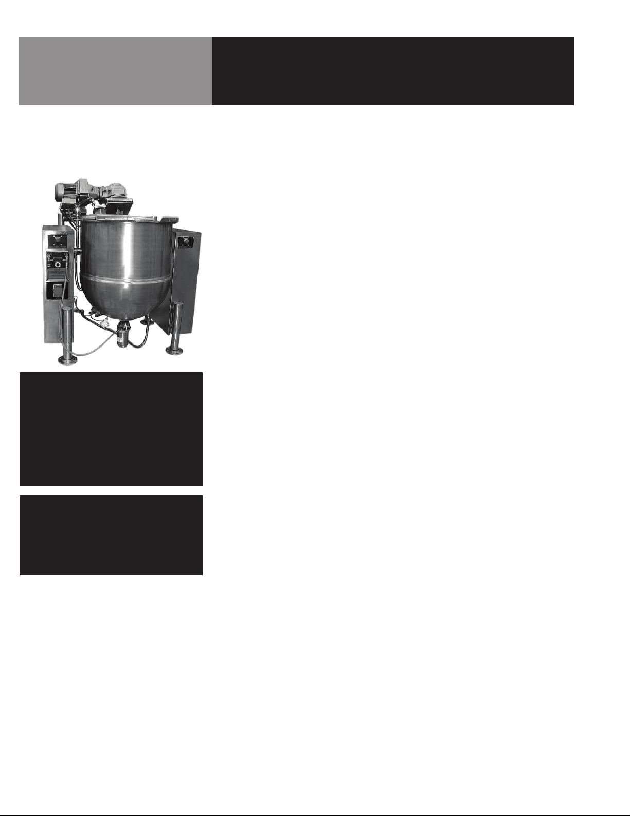
Equipment Description
GROEN MODEL
INA/2-100 TW Kettle
NOTE
THE GROEN EQUIPMENT YOU HAVE PURCHASED
HAS BEEN CONSTRUCTED FROM QUALITY
MATERIALS AND HAS BEEN CAREFULLY
INSPECTED AND TESTED TO ENSURE THAT
YOU RECEIVE THE BEST POSSIBLE PRODUCT.
WITH REASONABLE CARE AND PERIODIC
MAINTENANCE, YOUR GROEN UNIT SHOULD
PROVIDE YEARS OF PRODUCTIVE SERVICE.
The INA/2-100 TW Kettle is a hemispheric bottom, steam jacketed kettle, with an inclined
agitator that provides gentle yet thorough mixing of a broad range of products and enhanced
suspension of ingredient solids during product transfer. The kettle comes standard with a 90
PSI maximum pressure rating, an air-operated drop-down valve and a variable-speed agitator
drive.
The kettle offers the following features:
• Hemispherical bottom jacket designed for up to 100 PSI working pressure, built to ASME
Code and National Board registered. Kettle will operate dependably at any steam pressure
between 35 PSI and 100 PSI.
• Spiral baffle for efficient cold water jacket cooling.
• Type 316 stainless steel inner hemisphere and all wetted parts. Type 304 stainless steel
elsewhere.
• Interior and exterior of kettle finished to a No. 3 Sanitary Finish.
• 3” air operated, flush bottom, drop down, stainless steel product transfer valve.
• Stainless steel stand with adjustable stainless steel floor flanges standard.
• Heavy reinforced bar rim.
• 3/4” swing spout faucet mounted at kettle rim.
• Manufactured to latest sanitary standards and HACCP compliant.
• Inclined, easily removable agitator, with removable nylon edge side scraping blades which
scrape entire heat exchange surface below kettle rim.
• Variable speed motor drive with 9-36 rpm operating range.
• Flush mounted temperature sensor.
• Emergency stop switch.
• Vacuum breaker and safety valve supplied and factory mounted.
• Enclosed water and steam piping and solenoid valves.
• Motorized tilt of the kettle body and attached agitator.
• Butterfly-shaped pour lip.
• Safety Guard with integral interlock.
• Compressed air outputs for drop-down valve and pump/fill station.
• 208Vac receptacle for pump/fill station.
NOTE
PLEASE READ THIS MANUAL CAREFULLY
BEFORE YOU INSTALL OR OPERATE
YOUR EQUIPMENT. It contains information
you will need to install, operate, and
maintain the equipment properly.
4 OM-INA/2-100 TW

Installation
UNPACKING AND INSPECTION
WARNING
SOME INA/2 KETTLES MAY BE
UNBALANCED. CARE SHOULD BE
TAKEN IN HANDLING THEM DURING
EQUIPMENT PLACEMENT.
LOCATING THE KETTLE
LEVEL THE KETTLE
ANCHOR THE KETTLE
The equipment will arrive in a crate. Immediately upon receipt, carefully inspect the crate for
exterior damage. Open the crate and inspect the unit for concealed damage. Carefully read the
bill of lading and check that all items shipped are with the unit. Report any shipping damage or
missing items to the delivery agent. Record the model number, serial number, and installation
date for your unit and file this information for future reference.
To remove the equipment from the crate, pull the side boards loose from the top of the crate,
taking care not to damage the unit with tools or nails. Remove first the top, then the sides,
and then the cross-piecing that holds the unit down. When installation is to begin, lift the unit
straight up off the skid. During the installation process, it is important to properly support the
equipment until it is properly anchored in its permanent position.
Identify the desired location for the kettle. Check its position for operational clearances and
line-of sight to the control panel. Consider the movement of the motor on its carriage, room for
access for the kettle operator(s), and clearance for the tilting agitator or tilting kettle assembly.
If this system has a hoist and rail over the kettle normally the rail is located over the center of
the kettle.
Once the kettle is oriented as the job site dictates, Level the kettle by adjusting the flanged feet
and using the rim as a reference, leveling from front to back and side to side.
Bolt the leg flanges to the floor. It is crucial that they be anchored securely to the floor.
UTILITY CONNECTIONS
TO THE KETTLE
Use the kettle documentation included in this manual and the layout utility prints to locate
where all the necessary utilities need to be connected. Some of the connections are:
• steam in
• chilled water in
• hot and cold potable water in
• air in
• electric power in
• control panel wiring in to the terminal block on the left console of the kettle (for factory
terminated wiring of the speed control, temperature sensors, tilt safety switch, emergency
stop switch, etc.)
• condensate out
• chilled water out
• kettle jacket drain
• kettle food valve
• etc.
The kettle may or may not have all the above referenced utilities and can be ordered pre-piped
and pre-wired. Take the time to lay out all the utilities your kettle requires before you start this
installation. Keep in mind the kettle food valve under the kettle will have to be accessed many
times a day, and taken off for cleaning every day. The temperature probe also requires removal
and cleaning daily.
OM-INA/2-100 TW 5

Installation
STEAM SUPPLY
SAFETY RELIEF VALVE
SAFETY WARNING
Connect the steam supply to the steam inlet fitting(s). A strainer, check valve, union, and shut
off valve are required to be placed in the kettle’s steam supply line near the kettle. The automatic valves that are operated by the kettle control panel are included in the piping provided
with the kettle.
Dissimilar piping materials require a dielectric coupling. To obtain the full heating capacity of the
kettle use a steam supply line that is at least as large the kettle’s steam inlet fitting. The steam
line size may need to be enlarged to overcome line losses in longer piping runs or to accommodate other equipment being supplied from the same steam line. Steam pressure must be
restricted to the working pressure rating of the kettle. A steam pressure gauge should be installed
in the steam system piping in a prominent location and the appropriate safety valves utilized.
Close attention to line sizing, filtration, hydraulic snubber (water hammer eliminators), back flow
preventer, length of run, insulation, etc. when you are designing this system. The equipment will
not work without the correct amount of steam and proper pressure differential between steam
and condensate lines. It is the customer’s responsibility to for proper design of this system for the
equipment to work correctly. Water treatment, cleaning of strainers, and/or replacement of parts
from improper steam treatment and/or design is the customer’s responsibility.
A safety relief valve must be utilized that is rated to relieve at a pressure no higher than (the
Maximum Allowable Working Pressure, MAWP) stamped on the kettle’s National Board nameplate. This part is included in the kettle’s scope of supply. The valve will come pre-installed.
Do not allow the relief valve outlets or levers to be blocked. Route relief valve discharge lines so
that personnel cannot be injured when the valve relieves, normally within 6 inches of the floor.
CONDENSATE RETURN
COOLING WATER SUPPLY
6 OM-INA/2-100 TW
Install a condensate return line with a properly sized condensate trap, check valve, shutoff
valve, and union from the kettle jacket to the boiler’s condensate return system if available. The
unit also has automatic valves that are controlled by the kettle control panel. These parts are
included in the scope of supply.
Condensate pumped return with condensate lift stations may be required for the equipment
to work correctly. System design following national, state, and local codes needs to be taken
into account when designing the condensate system. Otherwise, pipe the condensate return
line to drain being careful to comply with national, state, and local codes governing discharge
temperatures.
Dissimilar piping materials require a dielectric coupling.
Install chilled supply line to the kettle inlet fitting(s). A strainer, check valve, union, and shut off
valve are included in the kettle’s chilled water supply line. The unit also has automatic valves
controlled by the kettle control panel. These parts are included in the scope of supply.
Dissimilar piping materials require a dielectric coupling.
To obtain the full cooling capacity of the kettle use a chilled water supply line that is at least as
large the kettle chilled water inlet fitting. The chilled water supply line size may need to be enlarged to overcome line losses in longer piping runs or to accommodate other equipment being
supplied from the same line. Close attention to line sizing, filtration, hydraulic snubbers (water
hammer eliminators), and correct pressure differential between the supply and return lines, and
following national and local codes needs to be taken into account when designing this system.
It is the customer’s responsibility to for proper design of this system for the kettle to work correctly. The water must be kept clean and free foreign materials and properly treated to prevent
deposits on the valves and inside the kettle jacket.
 Loading...