

Groen HYPERSTEAM HY-3E, HYPERSTEAM (2)HY-3E, HYPERSTEAM HY-5E, HYPERSTEAM (2)HY-5E Operator's Manual
OPERATOR MANUAL
IMPORTANT INFORMATION, KEEP FOR OPERATOR
1055 Mendell Davis Drive, Jackson, MS 39272
888-994-7636, fax 888-864-7636
unifiedbrands.net
THIS MANUAL MUST BE RETAINED FOR FUTURE REFERENCE. READ,
UNDERSTAND AND FOLLOW THE INSTRUCTIONS AND WARNINGS
CONTAINED IN THIS MANUAL.
FOR YOUR SAFETY Do not store or use gasoline or other flammable vapors
and liquids in the vicinity of this or any other appliance.
PART NUMBER 148666, REV. I (02/19)
This manual provides information for:
HYPERSTEAM™ ATMOSPHERIC
CONVECTION STEAMER
MODELS HY-3E, (2)HY-3E, HY-5E
& (2)HY-5E
WARNING Improper installation, adjustment, alteration, service or
maintenance can cause property damage, injury or death. Read the
installation, operating and maintenance instructions thoroughly before
installing or servicing this equipment.
NOTIFY CARRIER OF DAMAGE AT ONCE It is the responsibility of the
consignee to inspect the container upon receipt of same and to determine
the possibility of any damage, including concealed damage. Unified
Brands suggests that if you are suspicious of damage to make a notation
on the delivery receipt. It will be the responsibility of the consignee to file
a claim with the carrier. We recommend that you do so at once.
Manufacture Service/Questions 888-994-7636.
EQUIPMENT DESCRIPTION
Your Groen HY-3E or HY-5E HyPerSteam Convection Steamer is designed to give
years of service. It has a stainless steel cavity (cooking chamber) served by
an independent atmospheric steam generator which is electrically heated. A
powerful blower circulates the steam in the cavity to increase heating efficiency.
The cavity holds up to three (HY-3E) or five (HY-5E) standard steam table pans.
An 18 gauge stainless steel case encloses the cavity, the steam generator and
the control compartment that houses electrical components. Door hinges are
reversible (the door may be set to open from the left or right). Operating Controls
are on the front panel.
Model HY-3E steamers and HY-5E steamers are equipped with fully electronic
controls and a button activated, pre-programmed DELIME cycle. These units are
readily identified by their unique control panels, with touch pad controls, and the
distinctive symbol for steam integrated into the panel.
Both units are distinguished by the addition of a “fuse box” which allows the
operator to change fuses without removing panels.
The drain system on all models includes a spray condenser, which helps keep
steam from escaping from the chamber and cools drain water.
REFERENCES
UNDERWRITERS LABORATORIES, INC.
333 Pfingsten Road
Northbrook, Illinois 60062
NFPA – NATIONAL FIRE PROTECTION
ASSOCIATION
1 Batterymarch Park
Quincy, Massachusetts 02169
NSF INTERNATIONAL
789 N. Dixboro Rd.
P.O. Box 130140
Ann Arbor, Michigan 48113
ANSI – AMERICAN NATIONAL
STANDARDS INSTITUTE
1899 L Street, NW, 11th Floor
Washington, DC 20036
CSA INTERNATIONAL
178 Rexdale Blvd.
Toronto, ON
Canada M9W1R3
ICC – INTERNATIONAL CODE COUNCIL
500 New Jersey Avenue, NW
6th Floor, Washington, DC 20001
INSPECTION & UNPACKING
CAUTION: SHIPPING STRAPS ARE UNDER TENSION AND CAN SNAP BACK WHEN CUT.
CAUTION: THE HY-5E WEIGHS 230 POUNDS (104 KG). THE THE HY-3E WEIGHS 180
The HY-3E or HY- 5E will be delivered completely assembled in a heavy crate
attached to a skid. On receipt, inspect the crate carefully for exterior damage.
Carefully cut the straps around the crate and detach the crate from the skid. Be
careful to avoid personal injury or equipment damage from staples which might
be left in the crating.
Write down the model number, serial number and installation date. Keep this
information for reference. Space for these entries is provided at the top of the
Service Log in the back of this manual.
When starting installation, lift the unit straight up off the skid. Check packing
materials to make sure loose parts such as the condensate drip tray are not
discarded with the packing material.
TAKE CARE TO AVOID PERSONAL INJURY OR DAMAGE TO THE UNIT BY
STAPLES LEFT IN THE WALLS OF THE CARTON.
POUNDS (82 KG). YOU SHOULD GET HELP AS NEEDED TO LIFT THIS
WEIGHT SAFELY.
Information contained in this document is known to be current and accurate at the time of printing/creation. Unified Brands recommends
referencing our product line websites, unifiedbrands.net, for the most updated product information and specifications. © 2019 Unified Brands.
All Rights Reserved. Unified Brands is a wholly-owned subsidiary of Dover Corporation.

IMPORTANT - READ FIRST - IMPORTANT
WARNING: THE UNIT MUST BE INSTALLED BY PERSONNEL QUALIFIED TO WORK WITH
ELECTRICITY AND PLUMBING. IMPROPER INSTALLATION CAN CAUSE INJURY
TO PERSONNEL AND/OR DAMAGE TO THE EQUIPMENT. THE UNIT MUST BE
INSTALLED IN ACCORDANCE WITH APPLICABLE CODES.
CAUTION: SHIPPING STRAPS ARE UNDER TENSION AND CAN SNAP BACK WHEN CUT.
CAUTION: DO NOT INSTALL THE UNIT IN ANY WAY WHICH WILL BLOCK THE RIGHT SIDE
VENTS, OR WITHIN 12 INCHES OF A HEAT SOURCE SUCH AS A BRAISING PAN,
DEEP FRYER, CHARBROILER OR KETTLE.
CAUTION: LEVEL THE UNIT FRONT TO BACK, OR PITCH IT SLIGHTLY TO THE REAR, TO AVOID
DRAINAGE PROBLEMS.
WARNING: TO AVOID DAMAGE OR INJURY, FOLLOW THE WIRING DIAGRAM EXACTLY WHEN
CONNECTING A UNIT.
CAUTION: DO NOT USE PLASTIC PIPE. DRAIN MUST BE RATED FOR BOILING WATER.
WARNING: DO NOT CONNECT THE DRAIN DIRECTLY TO A BUILDING DRAIN.
WARNING: BLOCKING THE DRAIN IS HAZARDOUS.
IMPORTANT: IMPROPER DRAIN CONNECTION WILL VOID WARRANTY.
IMPORTANT: DO NOT ALLOW ANY WATER TRAPS IN THE DRAIN LINE. A TRAP CAN CAUSE
PRESSURE TO BUILD UP INSIDE THE CAVITY DURING STEAMING, WHICH WILL
MAKE THE DOOR GASKET LEAK.
WARNING: WHEN YOU OPEN THE DOOR, STAY AWAY FROM STEAM COMING OUT OF THE
UNIT. STEAM CAN CAUSE BURNS.
WARNING: BEFORE CLEANING THE OUTSIDE OF THE STEAMER, DISCONNECT THE ELECTRIC
POWER SUPPLY. KEEP WATER AND CLEANING SOLUTIONS OUT OF CONTROLS
AND ELECTRICAL COMPONENTS. NEVER HOSE OR STEAM CLEAN ANY PART OF
THE UNIT.
WARNING: ALLOW COOKING CHAMBER TO COOL BEFORE CLEANING.
WARNING: CAREFULLY READ THE WARNINGS AND FOLLOW THE DIRECTIONS ON THE LABEL
OF EACH CLEANING AGENT. USE SAFETY GLASSES AND RUBBER GLOVES AS
RECOMMENDED BY DE-LIMING AGENT MANUFACTURER.
WARNING: DO NOT MIX DE-LIMING AGENTS (ACID) AND DE-GREASERS (ALKALI).
WARNING: DO NOT PUT HANDS OR TOOLS INTO THE COOKING CHAMBER UNTIL THE FAN HAS
STOPPED TURNING.
WARNING: DO NOT OPERATE THE UNIT UNLESS THE REMOVABLE LEFT AND RIGHT SIDE PANELS
HAVE BEEN RETURNED TO THEIR PROPER LOCATIONS.
NOTICE: DO NOT USE A CLEANING OR DE-LIMING AGENT THAT CONTAINS ANY SULFAMIC
ACID OR ANY CHLORIDE, INCLUDING HYDROCHLORIC ACID. IF THE CHLORIDE
CONTENT OF ANY PRODUCT IS UNCLEAR, CONSULT THE MANUFACTURER.
NOTICE: DO NOT USE ANY DE-GREASER THAT CONTAINS POTASSIUM HYDROXIDE OR
SODIUM HYDROXIDE OR THAT IS ALKALINE.
WARNING: USE OF ANY REPLACEMENT PARTS OTHER THAN THOSE SUPPLIED BY GROEN OR
THEIR AUTHORIZED DISTRIBUTOR VOIDS ALL WARRANTIES AND CAN RESULT IN
BODILY INJURY TO THE OPERATOR AND DAMAGE THE EQUIPMENT. SERVICE BY
OTHER THAN FACTORY AUTHORIZED PERSONNEL WILL VOID ALL WARRANTIES.
WARNING: HIGH VOLTAGE EXISTS INSIDE CONTROL COMPARTMENTS. DISCONNECT FROM
BRANCH BEFORE SERVICING. FAILURE TO DO SO CAN RESULT IN SERIOUS INJURY
OR DEATH.
INSTALLATION
WARNING: THE UNIT MUST BE INSTALLED BY PERSONNEL WHO ARE QUALIFIED TO
CAUTION: DO NOT INSTALL THE UNIT WITH THE RIGHT OR LEFT SIDE VENTS BLOCKED
CAUTION: EACH UNIT MUST HAVE A SEPARATE GROUND WIRE FOR SAFE OPERATION.
WARNING: TO AVOID DAMAGE OR PERSONAL INJURY, FOLLOW THE ELECTRICAL
WARNING: DO NOT CONNECT THE DRAIN DIRECTLY TO A BUILDING DRAIN. BLOCKING
CAUTION: DO NOT USE PLASTIC PIPE. DRAIN MUST BE RATED FOR VERY HOT WATER.
ELECTRICAL SUPPLY CONNECTION
1. Panel Removal: Open the wiring and control panel by removing the screws on
2. Supply Voltage: The unit must be operated at the rated nameplate voltage.
3. Phase Selection: Refer to heater schematics for wiring information.
4. Terminal Block: The terminal block for incoming power is located at the back
5.
WORK WITH GAS, ELECTRICITY AND PLUMBING. IMPROPER INSTALLATION
CAN CAUSE INJURY TO PERSONNEL AND/OR DAMAGE TO THE EQUIPMENT.
THE UNIT MUST BE INSTALLED IN ACCORDANCE WITH APPLICABLE CODES.
THE UNIT MUST BE INSTALLED BY A LICENSED PLUMBER OR GAS FITTER
WHEN INSTALLED WITHIN THE COMMONWEALTH OF MASSACHUSETTS.
OR WITHIN 12 INCHES OF A HEAT SOURCE (SUCH AS A BRAISING PAN,
DEEP FRYER, CHAR BROILER OR KETTLE). TO AVOID DRAINAGE PROBLEMS,
LEVEL THE UNIT FRONT TO BACK.
SCHEMATIC EXACTLY WHEN CONNECTING THE UNIT.
THE DRAIN IS HAZARDOUS.
the right side panel. Slide the panel forward, and set it aside.
of the control compartment. The ground terminal is located in the wiring
compartment near the terminal block.
Supply Wire: To determine the type of wire you need for the power supply, find the
operating voltage and number of phases on the unit data plate. Refer to the table
below or to the label on the unitʼs back for correct wire size and temperature
rating. The equipment grounding wire must comply with the National Electrical
Code (NEC) requirements. The schematic on the inside of the unitʼs right side
cover gives directions for proper connection of the terminal block jumpers. The
specified wire must be used, or the unit will not meet Underwriters Laboratories
and NEC requirements. The knockout hole is sized for a ¾ inch conduit fitting on
the HY-3E and for a 1 inch conduit fitting on the HY-5E.
FIELD WIRING TABLE - USE COPPER WIRE ONLY - INSULATION RATING THHN (90ºC)
VOLTAGE
(60 Hz
Only)
MODEL HY-3E HY-5E HY-3E HY-5E HY-3E HY-5E
480 3
PHASE
240 1
PHASE
240 3
PHASE
208 1
PHASE
208 3
PHASE
KW Field Wiring Rated Current Demand
8.1 15.5 14 AWG 12 AWG 10 Amps 18.6 Amps
8.1 15.5 8 AWG 4 AWG 33 Amps 64.6 Amps
8.1 15.5 10 AWG 8 AWG 20 Amps 37.3 Amps
8.1 15.5 8 AWG 4 AWG 39 Amps 74.5 Amps
8.1 15.5 10 AWG 6 AWG 23 Amps 43 Amps
6. Branch Circuit Protection: Each Steamer, including individual units of stacked
models, should have its own branch circuit protection and ground wire.
Current and power demands for each unit are as shown above.
WATER CONNECTION(S)
Install a check valve to prevent back flow in the incoming cold water line, as
required by local plumbing codes. Water pressure in the line should be between
30 and 60 PSIG and must deliver a flow rate of 1.5 to 3.0 gallons per minute. If
pressure is above 60 PSIG, a pressure regulator will be needed.
A ¾ inch female NH connector (garden hose type) is used to attach the water
supply to the inlet valve. Minimum inside diameter of the water feed line is ½
inch. Use a washer in the hose connection. Do not allow the connection to leak, no
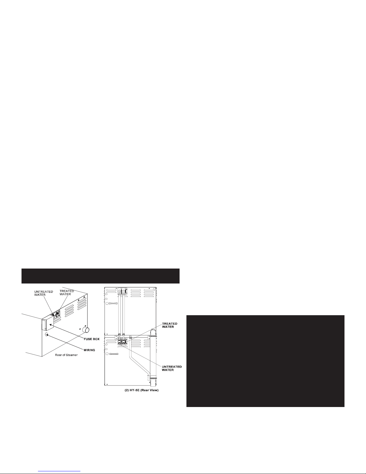
matter how slowly. The dual water standard connection, treated (softened) water
goes to the right (seen from the rear of the unit), and untreated water to the left.
Connections for both are made as shown below.
DRAIN CONNECTION
Level the steamer front to back, or pitch it slightly to the rear (maximum ¼ inch) by
adjusting the bullet feet on the stand or cabinet base.
2 OM-HY-3E/5E

A two inch (50mm) [HY-5E] or 1½ inch (38 mm) [HY-3E] ID hose should be attached
to the drain pipe supplied.
There must be a free air gap between the end of the hose and the building drain.
The free air gap should be as close as possible to the unit drain. There must also
be no other elbows or other restrictions between the unit drain and the two inch
free air gap.
Install the drain line with a constant downward pitch. IMPORTANT: Do not allow
water traps in the drain line. A trap can cause pressure build-up in the cavity,
which may cause the door gasket to leak.
FACTORY STACKED UNITS
WARNING: DO NOT CONNECT THE UNIT DRAIN DIRECTLY TO THE BUILDING DRAIN.
CAUTION: DO NOT USE PLASTIC PIPE. DRAIN MUST BE RATED FOR VERY HOT WATER.
This section is applicable only if you are installing factory-stacked units. If you
plan to stack steamers yourself, whether purchasing a new one for stacking or a
kit to stack two units you already own, you will require OM-HY-3E(S), RETROFIT
SUPPLEMENT (Part Number 121014). These instructions are also valid for stacking
HY-5E steamers.
Installing stacked steamers is similar to installing a single unit. The steamers are
stacked and assembled at the factory and delivered with the water connections
and drain hoses required for a single point connection.
1. Water Connection: The same water supply connection is used for both units. At
the water level inlet valve two 3/4” female NH connectors (garden hose type)
are used for the water supply. Treated water (softened) is connected to the
right valve fitting (looking from the rear of the unit) and untreated water to the
left fitting.
2. Electrical Supply Connection: Separate, individual electrical connections will
be required for each steamer in the stack. Each Steamer must have its own
branch circuit protection.
3. Drain Connection: Steamers must be leveled front to back, or pitched to the
rear (maximum 1/4 inch) by adjusting the bullet feet on the cabinet or stand
base.
For HY-3E a 1½ inch and for HY-5E a 2 inch ID hose may be attached to the
unit drain. It must be rated for boiling water.
Ensure that there is a free air gap between the end of the unit drain and the
building drain. This gap should be as close as possible to the unit drain. Do not
allow elbows or restrictions between the unit and the free air gap.
Rear view of (2) HY-5E. NOTE: Some drain parts (elbow, clamps) for single
models are packed inside the steamer cavity. Stacked units are factory
assembled. Installation is the same for stacked HY-5E and HY-3E units.
3 OM-HY-3E/5E
Proper Drain Line Connection. Drain Line must have a constant downward
pitch of at least 6 mm (¼”) per foot. Connection is 1½” for HY-3E, 2” for HY-5E.
(3)HY-3E shown.
COUNTER-MOUNTED UNITS
This section is applicable if the steamer will be mounted to a counter. All four
edges of the bottom of the steamer must be sealed with RTV to the counter if 4
inch legs are not used. Counter must be made of a noncombustible material such
as metal or tile.
OPERATION
WARNING: ANY POTENTIAL USER OF THE EQUIPMENT SHOULD BE TRAINED IN SAFE AND
WARNING: WHEN YOU OPEN THE DOOR, STAY AWAY FROM THE STEAM COMING OUT OF
CONTROLS
Operator controls are on the front right
of the unit. The control panel has the
following touch pads and indicator lights:
The timer is used in three ways:
1. The ON/OFF touch pad gets the
2. The READY indicator light shows that
3. When one probe is covered with lime
4. If the problem continues, both probes
5. The DELIME indicator light is lit when the unit is operating in the cleaning
6. The HI TEMP indicator light comes on when the steam generator is too hot. The
CORRECT OPERATING PROCEDURES.
THE UNIT. THE STEAM CAN CAUSE BURNS.
Done Light
Manual
Position/Light
Steamer Timer
Timing
Indicator Light
Power On/Off
Touch Pad
Power
HyPerSteam ready for use, or shuts it
off.
the steam generator is at standby
temperature and the cavity is hot
enough to begin steaming.
scale or fails, the DELIME light flashes
Indicator Light
Ready
Indicator Light
Service
(“De-Lime Me”)
Indicator Light
Cleaning
Indicator Light
Clean Cycle
Touch Pad
High Temp
Indicator Light
briefly every few seconds, but the unit
will continue to operate. Delime the
unit as soon as possible. The DELIME
light will flash until power is removed
from the unit, or the unit goes through
a clean cycle.
may fail. Then the steamer stops
working, and the SERVICE light is
lit. If DELIMING/CLEANING does
not correct, turn off the power and
contact an Authorized Groen Service
Representative for repair.
mode.
unit will automatically shut off, and cannot be turned on again until the steam
generator cools and the HI TEMP indicator light goes out.
7. The TIMING indicator light stays on when the timer is running.
8. The CLEAN touch pad is used to start the automatic 50 minute deliming cycle.
9. The timer is used in three ways:
a. In the OFF position the steam generator stays at a low boil or “holding”
temperature.
b. When a cook time is set, the unit steams until the timer runs down to OFF.
At that time steaming stops, a red light comes on and a beeper sounds.
c. With the timer turned to the ON position, the unit steams continuously. The
green light stays lit. The steamer will not time down.
OPERATING PROCEDURE
1. Press the ON switch/pad for the steamer. The steam generator will fill, and
heat until the READY light comes on. (About 10 minutes.)
2. Load food into pans in uniform layers. Pans should be filled to about the same
levels, and be even on top.
3. Open the door and slide the pans onto the supports. If you will only be steaming
one pan, put it in the middle position.
4. Close the door. With the READY indicator lit, take one of the following steps:
• If you want to steam the food for a certain length of time, set the timer
for that period. The timer will automatically run the steamer for the set
time and then turn it off. A red light will come on and a beeper will sound.
Steam production stops.
• To steam continuously, turn the timer to the manual ON position. A
green light will come on. The unit will continue steaming until you stop
it by turning the timer to OFF. When steaming continuously YOU MUST
CONTROL STEAMING TIME.
5. Open the door. Remove the pans from the steamer, using hot pads or oven
mitts to protect your hands from the hot pans.
6. To shut down the unit, press the ON/OFF touch pad to OFF. The steam generator
will automatically drain.
WATER QUALITY & TREATMENT
REDUCE SCALE PROBLEMS BY USING AND MAINTAINING A WATER SOFTENER FOR
YOUR STEAMER!
In some areas of the United States the water is low enough in mineral content to
avoid scale build-up. However, most water supplies carry heavy loads of minerals.
This will form scale in the steam generator, reduce its steam output, and possibly
cause premature component failure.
Your water utility or local water quality dealer can tell you about the minerals in
your water. The water going to the steam generator should have:
1. Between 1 and 30 ppm total dissolved solids (TDS)
2. A pH (acidity rating) of 7.0 - 8.0
3. Total alkalinity less than 120 ppm
4. Silica less than 13 ppm
5. Chlorides less than 30 ppm
6. Sulfates less than 40 ppm
7. Chlorine less than 10 ppm
Please follow these simple precautions:
1. Do not rely on unproven water treatment equipment which is sold for scale
prevention or scale removal. They frequently don’t work. The best way to
prevent scale is to supply the purest possible water.
2. If your water contains scale-forming minerals, as most water does, use a
well maintained water treatment system. Whether an exchangeable softener
cartridge or a regenerating system is chosen, a regular exchange system is
essential.
3. Installing a water meter on supply line to the steamer will provide an accurate
gauge of water use, and will help determine when to exchange cartridges or
regenerate the softener. Using treated water will provide longer generator life,
higher steam capacity, and reduce maintenance requirements.
4. If you notice a slowdown in steam production, check the steam generator for
scale build-up. Heavy scale reduces the unit’s ability to boil water, and can
even cause heating elements in the steam generator to overheat and burn out.
5. Steamers are available with two separate water intakes:
one for the steam generator (treated water)
one for the spray condenser (untreated water).
The steam generator only uses 14 to 31% of a steamer’s water. Since water
treatment systems are typically sized by total GPH (gallons per hour), the
second intake could reduce treatment requirements by up to 80%, resulting in
significant savings.
Models built since 1998 have a fuse box mounted on the rear.
On both the HY-3E and HY-5E, the dual water connections are side by side on the
rear of the unit. When seen from from the back of the unit, the treated (softened)
water intake is on the right.
It is essential that the steam generator be supplied with water that will not form
scale at an unacceptable rate. The boiler was engineered to minimize scale, but its
formation depends on water hardness and how much the unit is used.
4 OM-HY-3E/5E
CLEANING
WARNING: DISCONNECT THE POWER SUPPLY BEFORE CLEANING THE OUTSIDE OF THE
STEAMER. KEEP WATER AND CLEANING SOLUTIONS OUT OF CONTROLS
AND ELECTRICAL COMPONENTS. NEVER HOSE OR STEAM CLEAN ANY
PART OF THE UNIT. DON’T MIX DE-LIMING AGENTS (ACID) WITH DEGREASERS (ALKALI) ANYWHERE IN THE UNIT. AVOID CONTACT WITH
ANY CLEANERS, DE-LIMING AGENT OR DE-GREASER AS RECOMMENDED
BY THE SUPPLIER. MANY ARE HARMFUL. READ THE WARNINGS AND
FOLLOW THE DIRECTIONS! EVEN WHEN THE UNIT HAS BEEN SHUT OFF,
DON’T PUT HANDS OR TOOLS INTO THE COOKING CHAMBER UNTIL THE
FAN HAS STOPPED TURNING. DON’T OPERATE THE UNIT UNLESS THE
TWO REMOVABLE INTERIOR PARTITIONS HAVE BEEN PUT BACK IN THEIR
PROPER LOCATIONS. DON’T USE ANY CLEANING OR DELIMING AGENT
THAT CONTAINS ANY SULFAMIC AGENT OR ANY CHLORIDE, INCLUDING
HYDROCHLORIC ACID (HCL). TO CHECK FOR CHLORIDE CONTENT SEE ANY
MATERIAL SAFETY DATA SHEETS PROVIDED BY THE CLEANING AGENT
MANUFACTURER.
IMPORTANT
CAUTION: NEVER LEAVE A CHLORINE SANITIZER IN CONTACT WITH STAINLESS
: DO NOT USE ANY METAL MATERIAL (SUCH AS METAL SPONGES) OR METAL
IMPLEMENT (SUCH AS A SPOON, SCRAPER OR WIRE BRUSH) THAT MIGHT
SCRATCH THE SURFACE. SCRATCHES MAKE THE SURFACE HARD TO CLEAN
AND PROVIDE PLACES FOR BACTERIA TO GROW. DO NOT USE STEEL WOOL,
WHICH MAY LEAVE PARTICLES IMBEDDED IN THE SURFACE WHICH COULD
EVENTUALLY CAUSE CORROSION AND PITTING.
STEEL SURFACES FOR LONGER THAN 30 MINUTES. LONGER CONTACT CAN
CAUSE CORROSION.
RECOMMENDED TOOLS & CLEANERS:
• Groen Delimer/Descaler (Part Number 114800). Do NOT use any product
containing chlorides or sulfamic acid, including hydrochloric acid.
• Nylon scrub pad, cloth and/or sponge.
To keep your HY-3E or HY-5E Steamer in proper working condition, use the
following procedure to clean the unit. This regular cleaning will reduce the effort
required to clean the steam generator and cavity.
SUGGESTED CLEANING SUPPLIES
1. Mild detergent
2. Stainless steel exterior cleaner such as Zepper®
3. Steam generator de-liming agent, such as Groen Delimer Descaler. A liquid deliming agent will be easier to use than crystals or powders. See the warning
about chlorides.
4. De-greaser
5. Cloth or sponge
6. Plastic wool or a brush with soft bristles
7. Spray bottle
8. Measuring cup
9. Nylon pad
10. Towels
11. Plastic disposable gloves
12. Funnel
PROCEDURE
1. Outside
a. Prepare a warm solution of the mild detergent as instructed by the
supplier. Wet a cloth with this solution and wring it out. Use the moist cloth
to clean the outside of the unit. Do not allow freely running liquid to touch
the controls, the control panel, any electrical part, or any open louver.
b. To remove material which may be stuck to the unit, use plastic wool, a
fiber brush, or a plastic or rubber scraper with a detergent solution.
c. Stainless steel surfaces may be polished with a recognized stainless steel
cleaner such as Zepper®.
2. Steam Generator and Cooking Chamber
The steamer cavity and steam generator may be cleaned separately. Regular
deliming, depending on your steamer usage and local water quality, must be
done to enhance performance and prolong the life of your HyPerSteam™
convection steamer. Steamer must be turned off after every use to prevent
lime scale buildup - do not run steamer continuously. When cleaning is
scheduled, or the SERVICE light is on, follow the simple deliming instructions.
NOTE: ALWAYS USE HOT PADS OR MITTS WHEN HANDLING HOT STEAMER
PANELS OR RACKS. DON’T ALLOW DE-LIMING AGENTS TO MIX WITH
DEGREASERS.
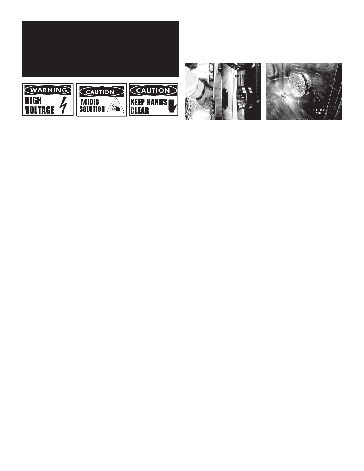
Once the cavity has cooled, reach in and
remove the fan baffle partition by lifting it
upward and drawing it toward the center of
the cavity.
Pour two cups of Groen de-liming solution into
the de-liming port.
DELIMING STEPS (USE TOUCH PAD)
STEP 1
Press ON/OFF to turn steamer off. Open door.
STEP 2
Let cavity cool for 5 minutes or longer. While cool, wipe out cavity. Close door.
STEP 3
Press and hold CLEAN while also turning steamer on by pressing ON/OFF, until
only DELIME and POWER lights remain on (all lights will turn on, then off, except
DELIME and POWER).
STEP 4
After 5 minutes, beeper will beep rapidly, signaling you to add Groen Delimer/
Descaler. Door(s) must remain closed for entire delime cycle.
STEP 5
Pour 1 pint (2 cups) of delimer PER CAVITY into upper and /or lower deliming port(s)
and then close port(s). Press CLEAN. Double-stacked unit cavities may be delimed
together or seperately
STEP 6
Delime cycle will start, taking about 30 minutes. When delime cycle is complete,
DELIME light will appear, DONE light will flash and beeper will beep.
STEP 7
Press ON/OFF to turn steamer off. Let cavity cool for 5 minutes or longer. Open
door, wipe out inside of cavity and wipe door gasket. Close door.
STEP 8
To use steamer, press ON/OFF. When READY light appears, steamer is ready to use.
NOTES:
• If DELIME light flashes rapidly (5 times per second), press DELIME to restart
delime cycle.
• If power outage occurs during deliming, delime cycle must be restarted. Press
DELIME.
• For best performance, do not interrupt delime cycle. If delime cycle must be
stopped, press ON/OFF to turn on. Set timer for 5 minutes. After beeper beeps,
press ON/OFF to turn off. Let cavity cool for 5 minutes or longer, carefully open
door(s) and wipe out cavity completely.
5 OM-HY-3E/5E
MAINTENANCE
NOTE: THE UNIT CONTAINS NO FUSES THAT SHOULD BE REPLACED BY THE
OPERATOR.
HY-3E and HY-5E Steamers are designed for minimum maintenance, and no user
adjustments should be necessary. Certain parts may need replacement after
prolonged use. If there is a need for service, only Groen personnel or authorized
Groen representatives should perform the work. Always supply water with a low
mineral count that meets the standards outlined in the Water Conditioning section
of this manual.
If steam or condensate is seen leaking from around the door, take the following
steps:
1. Check the door gasket. Replace if it is cracked or split.
2. Inspect the cooking chamber drain to be sure it is not blocked.
3. Adjust the latch pin to allow for changes that might occur as the gasket ages.
a. Loosen the lock nut at the base of the latch pin. Turn the latch pin ¼ turn
clockwise, and re-tighten the lock nut.
b. After adjustment, run the unit to test for further steam leakage.
c. If there is still leakage, repeat the adjustment.
d. Continue adjusting the pin clockwise until the door fits tightly enough to
prevent leakage.
REPLACEMENT PARTS
To order parts, contact your Authorized Service Agent. Supply the model
designation, serial number, part description, part number, quantity, and when
applicable, voltage and phase.
TROUBLESHOOTING
This unit is designed to operate smoothly and efficiently if properly maintained.
However, the following is a list of checks to make in the event of a problem.
Wiring diagrams are found at the end of this manual. When in doubt, turn unit
off and call for service at 888-994-7636. If an item on the check list is marked
with (X), it means that the work should be done by an Authorized Service Agent.
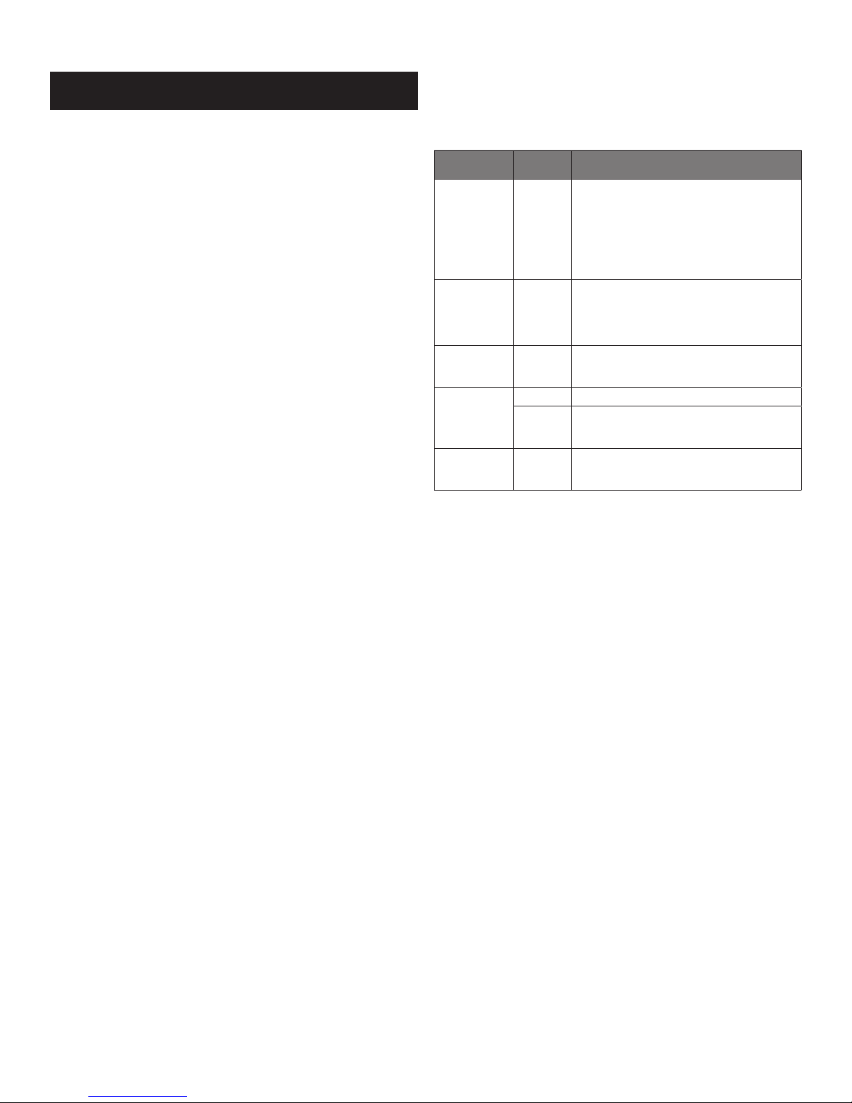
SYMPTOM WHO
Steam generator
does not fill with
water.
No steam. User a. Is the ON switch depressed?
Service light
comes on after
four minutes.
Excessive steam
escaping from rear
of unit.
High Limit
Indicator Light is
“ON.”
User a. Is the ON switch depressed?
User a. Is the water supply connected?
User a. Is the water spray hose kinked or obstructed?
Authorized
Service Rep
Only
Authorized
Service Rep
Only
X indicates items which must be performed by authorized technician.
b. Is the water supply connected?
c. Is the water turned on?
d. Check for low water pressure (less than 30 PSI or 210
kPa) OR low water flow (less than 5.7 liters (1.5
gallons) per minute.
e. Is the screen at the water connection clogged?
f. Has the steam generator been delimed?
b. Is the water supply connected?
c. Is the water turned on?
d. Are steamer doors open?
e. Is the steam generator limed up?
b. Is the water turned on?
c. Has the unit been delimed? (Refer to Cleaning Section)
b. Is the water spray solenoid connected? X
c. Is the drain properly vented? X
Reset the high limit thermostat after checking the
cause of high temperature and correcting it. (X)
(See Service Section)
WHAT TO CHECK
CONTACT US
If you have questions pertaining to the content in this manual, contact Unified
Brands at 888-994-7636.
6 OM-HY-3E/5E
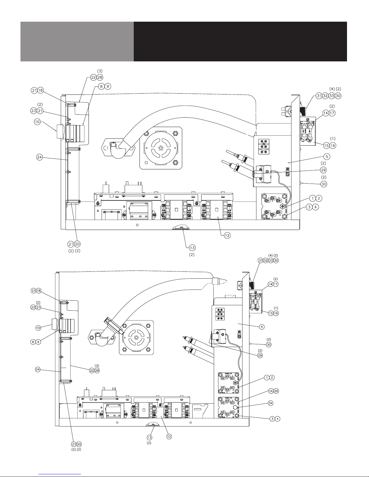
ELECTRICAL ASSEMBLY
Parts List
ELECTRICAL ASSEMBLY
148586 – HY-3E
7 OM-HY-3E/5E
148626 – HY-5E
ELECTRICAL ASSEMBLY
Parts List
Key Description Part # HY-3E HY-5E
1 ASSEMBLY, HEATER ELEMENT & T-STAT, 208V, 8KW 141846 X X
1 ASSEMBLY, HEATER ELEMENT & T-STAT, 240V, 8KW 142146 X X
1 ASSEMBLY, HEATER ELEMENT & T-STAT, 480V, 8KW 142148 X X
1A ASSEMBLY, HEATER ELEMENT, 208V, 8KW 141183 X
1A ASSEMBLY, HEATER ELEMENT, 240V, 8KW 141184 X
1A ASSEMBLY, HEATER ELEMENT, 480V, 8KW 141185 X
2 GASKET, HEATER Z042366 X X
3 NUT, HEX, 5/16-18 Z005602 X X
4 WASHER, LOCK, 5/16 Z005656 X X
5 ASSEMBLY, LINE CONNECTION PANEL 148587 X X
- HARNESS, CONTROL 148111 X X
- HARNESS, HEATER 148113 X
- HARNESS, HEATER 148115 X
- HARNESS, POWER 148112 X X
8 TIMER, STEAMER, 24VAC, 60HZ Z096826 X X
9 NUT, ROTARY SHAFT SEAL, 3/8-32 101145 X X
10 KNOB, TIMER 123100 X X
12 ASSY, CHASSIS, HY-3/5E 148574 X X
13 NUT HEXAGON KEPS 10-32 Z071256 X X
14 FUSE BLOCK COMPARTMENT ASSEMBLY 119848 X X
15 COVER, FUSE BLOCK COMPARTMENT 119846 X X
16 SCREW, HEX WSHR HD, #8-32, 1/4" LONG Z074242 X X
17 SCREW, HEX WSHR HD, 10-32, 3/8" LONG Z069773 X X
18 STANDOFF, 6-32, 1-1/4" LONG 119827 X X
20 STANDOFF, 6-32, 3/4" LONG 119826 X X
21 NUT, LOCK, NYLON INSERT, 6-32 119855 X X
22 COVER, PANEL CONTROL 143255 X X
23 LIGHT & TIMER PC BOARD ASSEMBLY 137233 X X
24 STEAMER CONTROL BOARD ASSEMBLY 141082 X X
- HARNESS, JUMPER, VOLTAGE SELECT, 18GA 123124 X X
- HARNESS, TIMER MOTOR 123120 X X
- HARNESS, JUMPER, CONTROL BD TO RIBBON CONN 123122 X X
28 NUT, HEX KEPS, 6-32 Z071289 X X
29 SCREW, RND HD, SELF-TAP, 6-32, 3/8" LONG Z012398 X X
30 SCREW, TRS HD, 10-32, 3/8" LONG Z004173 X X
31 VALVE, WATER, SINGLE WAY 100934 X X
32 PLATE, COVER, DOUBLE WATER INLET 101199 X X
33 SCREW, TRS HD, 8-32, 3/8" LONG Z005764 X X
34 PLUG, PIPE, 1/4 NPT, HEX HD, 304SS Z004145 X
8 OM-HY-3E/5E
PLUMBING ASSEMBLY
Parts List
Key Description Part # HY-3E HY-5E
- BRACKET, STEAM DEFLECTOR 118157 X X
- BRKT TUBE ASSY & "L" HY-5E 125950 X X
- CLAMP, HOSE, WORM DRIVE, Z093482 X X
- CLAMP, HOSE, CONSTANT TENSION, CTB-16 127522 X X
- CLAMP, HOSE, CONSTANT TENSION, CTB-17 127523 X
- CLAMP, HOSE, CONSTANT TENSION, CTB-19 126095 X
- CLAMP, HOSE, CONSTANT TENSION, CTB-24 127524 X
- CLAMP, HOSE, CONSTANT TENSION, CTB-27 138457 X
- CLAMP, HOSE, CONSTANT TENSION, CTB-40 148307 X
- CLAMP, HOSE, CONSTANT TENSION, CTB-47 127526 X X
- CLAMP, HOSE, DOUBLE WIRE, DW-12 127662 X X
- CLAMP, HOSE, DOUBLE WIRE, DW-9.5 127527 X X
- CLAMP, HOSE, SINGLE WIRE, HC-38 126010 X
- HOSE, REINFORCED RUBBER, BLACK, 3/8 ID, 31-1/4" LONG 125994 X
- HOSE, REINFORCED RUBBER, BLACK, 3/8 ID, 26-1/2" LONG Z096807 X
- HOSE, REINFORCED RUBBER, BLACK, 3/8 ID, 20" LONG 142261 X
- HOSE, REINFORCED RUBBER, BLACK, 3/8 ID, 4" LONG 142271 X
- HOSE, REINFORCED SILICONE, 1-1/2 ID, 2-1/2" LONG 122873 X
- HOSE, REINFORCED SILICONE, 2 ID, 3-1/2" LONG 125955 X
- HOSE, REINFORCED PVC, CLEAR, 3/8" ID, 21" LONG Z096773 X
- HOSE, SANTOPRENE, 3/4 ID, STEAM INLET, 11-1/2" LONG Z088870 X
- HOSE, SANTOPRENE, 3/4 ID, STEAM INLET, 18-3/4" LONG 125954 X
- HOSE, SANTOPRENE, 1-1/8 ID, STEAM INLET, 17" LONG 123867 X
- HOSE, SANTOPRENE, 1-1/2 ID, STEAM INLET, 18" LONG 126008 X
- REDUCER, WATER FLOW (.055 ID) 112720 X
- REDUCER, WATER FLOW (.078 ID) Z088877 X
- SCREW TRS HD 10-32 X 3/8" Z004173 X X
- ASSEBMLY, DRAIN TUBE, HY-3E 123115 X
- ASSEBMLY, DRAIN TUBE, HY-5E 125918 X
- TEE, BARBED, 3/8 HOSE 138432 X
9 OM-HY-3E/5E
 Loading...