

Page 1
IMPORTANT INFORMATION
IMPORTANT INFORMATION KEEP FOR OPERATOR
IMPORTANT INFORMATION IMPORTANT INFORMATION
KEEP FOR OPERATOR IMPORTANT INFORMATION
KEEP FOR OPERATOR KEEP FOR OPERATOR
IMPORTANT INFORMATION
IMPORTANT INFORMATION IMPORTANT INFORMATION
E-CC-MOLAUNAM ROTAREPO
Part Number 121015 Rev. A DOMESTIC
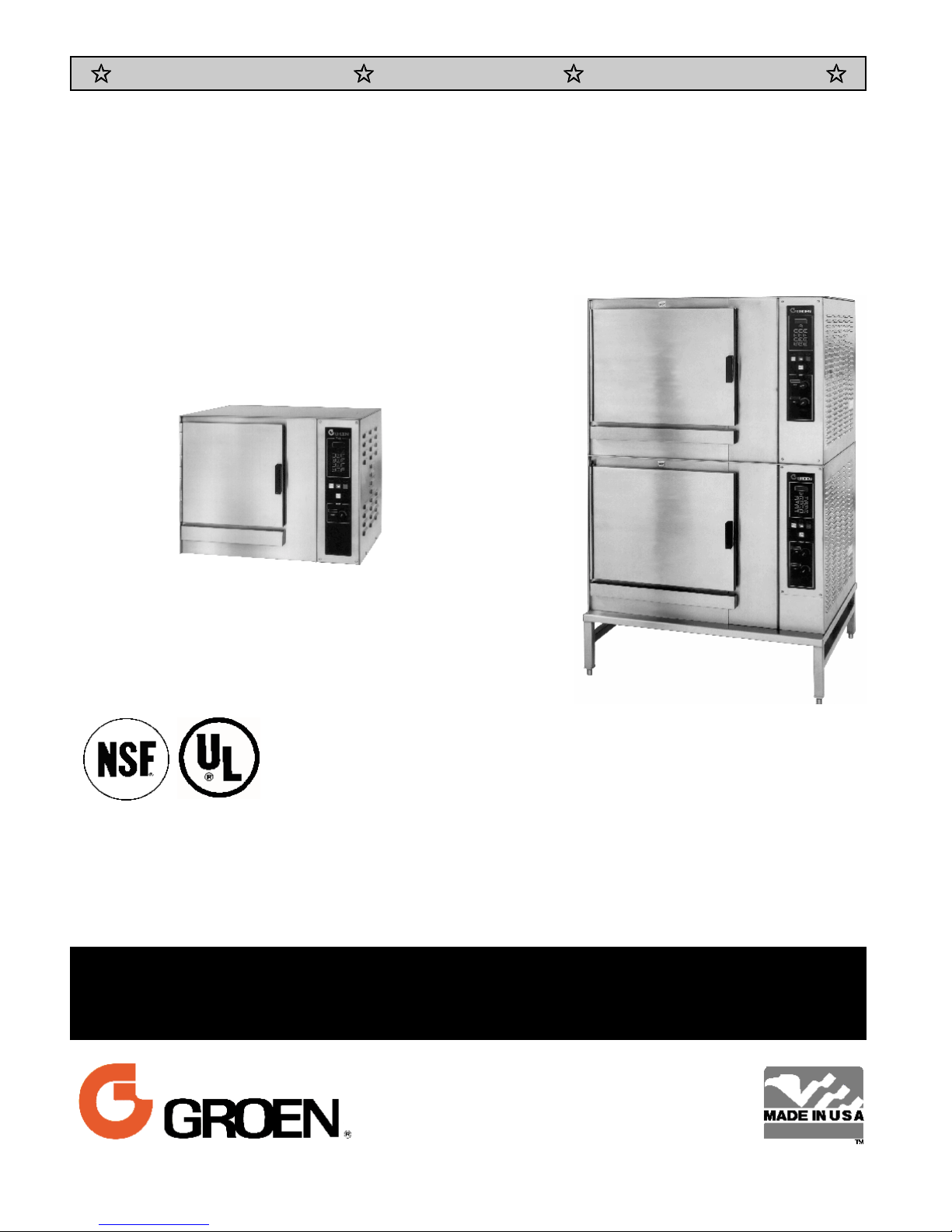
MODEL: CC-E
CONVECTION COMBO™
Combination Steamer-Oven
CC10-E
CC20-EF
THIS MANUAL MUST BE RETAINED FOR FUTURE REFERENCE. READ,
UNDERSTAND AND FOLLOW THE INSTRUCTIONS AND WARNINGS
CONTAINED IN THIS MANUAL.
FOR YOUR SAFETY
DO NOT STORE OR USE GASOLINE OR OTHER FLAMMABLE VAPORS AND
LIQUIDS IN THE VICINITY OF THIS OR ANY OTHER APPLIANCE
.
Information contained in this document is
known to be current and accurate at the time
of printing/creation. Unified Brands recommends referencing our product line websites,
unifiedbrands.net, for the most updated
product information and specifications.
Page 2

OM-CC-E
IMPORT ANT — READ FIRST — IMPORTANT
WARNING:
CAUTION: SHIPPING STRAPS ARE UNDER TENSION AND CAN SNAP BACK WHEN CUT.
CAUTION:
CAUTION:
WARNING: TO AVOID DAMAGE OR INJURY, FOLLOW THE WIRING DIAGRAM EXACTLY WHEN
CAUTION:
WARNING:
WARNING:
IMPORTANT:
IMPORTANT:
WARNING:
THE UN IT MUST BE INSTALLED BY PERSONN EL QUALIFIED TO WORK WITH ELECTRICITY
AND PLUMBING. IMPROPER INSTALLATION CAN CAUSE INJURY TO PERSONNEL AND/OR
DAMAGE TO THE EQU IPMENT. THE UNIT MUST BE INSTALLED IN A CCORDANCE WITH
APPLICABLE CODES.
DO NOT INSTALL THE UNIT IN ANY WAY WHICH WILL BLOCK THE RIGHT SIDE VENTS,
OR WI THIN 12 I NCH ES O F A H EAT SOURCE SUCH A S A BRAISIN G PAN , DEEP FRYER,
CHAR BROILER OR KETTLE.
LEVEL THE UNIT FRONT TO BACK, OR PITCH IT SLIGHTLY TO TH E REA R, TO A VOID
DRAINAGE PROBLEMS.
CONNECTING A UNIT.
DO NOT USE PLASTIC PIPE. DRAIN MUST BE RATED FOR BOILING WATER.
DO NOT CONNECT THE DRAIN DIRECTLY TO A BUILDING DRAIN.
BLOCKING THE DRAIN IS HAZARDOUS.
Improper drain connection will void warranty.
Do not al low any wat er traps in t he line. A t rap can cause pressure t o build up inside t he
cavit y during steaming, which will make the door gasket leak.
WHEN YOU OPEN THE DOOR, STAY AW AY FROM STEAM COMI NG OUT OF THE UNIT.
STEAM CAN CAUSE BURNS.
WARNING: BEFORE CLEANING THE OUTSIDE OF THE STEAMER, DISCONNECT THE ELECTRIC POWER
SUPPLY. KEEP WATER AND CLEANING SOLUTIONS OU T OF CON TROLS AN D ELECTRICAL
COMPONEN TS. NEVER HOSE OR STEAM CLEAN ANY PART OF THE UNIT.
WARNING:
WARNING:
WARNING:
WARNING: DO NOT PUT HANDS OR TOOLS INTO THE COOKING CHAMBER UNTIL THE FAN HAS
WARNING:
NOTICE:
NOTICE:
WARNING:
ALLOW COOKING CHAMBER TO COOL BEFORE CLEANING.
CAREFULLY READ THE WARNINGS AND FOLLOW THE DIRECTIONS ON THE LABEL OF EACH
CLEANING AGENT.
DELIMING AGENT MANUFACTURER.
DO NOT MIX DE-LIMING AGENTS (ACID) AND DE-GREASERS (ALKALI).
STOPPED TURNING.
DO NOT OPER ATE THE UNIT UNLESS THE R EMOVA BLE RIG HT SIDE PANEL H AS BEEN
RETURNED TO ITS PROPER LOCATION.
DO NOT USE A CLEANING OR DE-LIMING AGENT THAT CONTAINS ANY SULFAMIC ACID
OR ANY CHLORIDE, INCLUDING HYDROCHLORIC ACID. IF THE CHLORIDE CONTENT OF
ANY PRODUCT IS UNCLEAR, CONSULT THE MANUFACTURER.
DO NOT USE ANY DE-GREASER THAT CONTAINS POTASSIUM HYDROXIDE OR SODIUM
HYDROXIDE OR THAT IS ALKALINE.
USE OF ANY REPLACEMENT PARTS OTHER THAN THOSE SUPPLIED BY GROEN OR THEIR
AUTHORIZED DISTRIBUTOR VOIDS ALL WARRANTIES AND CAN RESULT IN BODILY INJURY
TO THE OPERATOR AND DAMAGE THE EQUIPMENT. SERVICE BY OTHER THAN FACTORYAUTHORIZED PERSONNEL WILL VOID ALL WARRANTIES.
USE SAFETY GLASSES A ND R UBBER GLOVES AS RECOMMENDED BY
WARNING:
HIGH VOLTAGE EXISTS INSIDE CONTROL COMPARTMENTS. DISCONNECT FROM BRANCH
BEFORE SERVICING. FAILURE TO DO SO CAN RESULT IN SERIOUS INJURY OR DEATH.
2
Page 3

Table of Contents
OM-CC-E
OPERATOR W ARNINGS
REFERENCES ..........................................................3
EQUIPMENT DESCRIPTION
INSPECTION AND UNPACKING
WATER CONDITIONING/REQUIREMENTS .....................................6
INSTALLATION AND START-UP INSTRUCTIONS
OPERATING INSTRUCTIONS
CLEANING ............................................................21
MA I NT ENA NCE
TROUBLESHOOTING
SERVICE LOG..........................................................30
........................................................
...................................................
................................................
.............................................
................................
..............................................
....................................................
2
4
5
7
13
24
25
WARRANTY PROTECTION
UNDERWRITERS LABORATORIES, INC.
333 Pfingst en Road
Northbrook, Illinois 60062
KLENZADE SALES CENTER
ECOLAB, Inc.
370 Wabasha
St. Paul , Minnesota 55102
800 328-3663 or 612 293-2233
................................................
31
References
NATIONAL FIRE PROTECTION
ASSOCIATION
60 Battery March Park
Quincy, Massac husetts 02269
NFPA/70 The National Electrical Code
NATIONAL SANITATION FO UNDATION
3475 Pl y m outh Road
Ann Arbor, Michigan 48106
3
Page 4

OM-CC-E
Equi p ment D escr i p ti o n
Your Groen Convection Combo™ has a stainless
steel cooking ch amber , a n a ir hea ting compa rtment
with electri c hea ting elements an d fan, a steam
generator with electric h eat ing elements, an d a
control compartment which houses other electrical
component s.
All m ajor compon ents of the Conv ection Combo™
are encased in a 16 gauge stainless st eel ca binet.
Glass fiber insulation, lines the cabinet at a thickness
of 1½ to 2 i nch es (4 to 5 cm ). A remov able drip tray
is locat ed benea th the door.
Door hinges are reversible so that doors ma y open
from t he left or r ight side. Operator controls are
located on the ri ght side of th e front panel.
Standard cont rols l et you to opera te the Con vection
Combo in a ny one of three cooking modes:
1. As a conv ection oven
2. As a self-contained, pressureless steamer
3. As a combination oven-steamer
Models CC10- E an d C C 20-E differ in cooking
chamber size and capacity:
CC10-E: 4 steam t able pans (12x20x2½”), or
7 half- size (13x18" ) U S bak ing pans
CC20-E: 10 steam t able pans (12x20x2½”), or
9 ful l-si ze (18x26") US baking pan s
The smaller Conv ection Combo™ is ava ilable as a
table- top unit (the single CC10-E ). These units a re
also supplied on a stain less steel stand as models
CC10-EF an d (2)CC 10-EF. The larger Con vection
Combo™ is alw a y s supplied with a stand as the
single CC20-EF or the double-stacked (2)CC 20-EF.
The Convection Combo™ Fam ily: 1. Model (2)CC20-EF (Full- sized double-stacked uni t on rigi d stand),
2. Model CC-20-EF ( Full-sized si ngle unit on a convenient stand), 3. Model (2)CC10-EF (Double-stacked,
stand- m ounted, half- pan C om bo, 4. Model CC10-EL singl e four inch l eg-mounted. (Also availabl e in
tabl etop (CC10-E) and stand-mounted (CC10-EF) versi ons.
4
Page 5

Insp ecti o n an d U n p acki n g
OM-CC-E
Your Convection Combo™ will be completely
assembled in a hea vy shipping car ton or w ooden
crate, and attach ed to a skid. On receipt, inspect
the carton or crate carefully for exter ior damage.
CAUTION
SHIPPING ST RAPS ARE UNDER TENS ION AND
CAN SN AP BA CK WHEN CUT.
Carefully cut the straps around the carton and detach
the sides of the carton from the skid. Pull the carton
up off the unit. Be careful to avoid personal injury or
equipm e nt d amage from staples which might be left in
the carton w alls.
Water Conditioning
It is essential to supply the steam generator with
water that will n ot form scale. Even though the
steam gen erator is engineered to minimize sca le
formati on, scal e development depends on the
hardness of your water and the number of hours you
operate t he equ ipmen t.
In some areas, water is low enough in mi ner al
content to avoid scale formation. But most water
supplies are full of minera ls which form scale. It is
this scale which could lead to an early component
failure.
Your water utility can tell you about the minerals in
your wa ter. The water going to the steam gen era tor
should h a v e between 30 and 40 parts per million
(ppm) total dissol ved solids (TDS) a nd sh ould ha ve a
pH (acidity rating) of 7. 0 to 9.0. Please follow t hese
simple precautions:
Do not rel y on unproven water treat m ents
1.
which a re sold for scale prevention or scale
removal. They don’t always work. The best
way to preven t scale is to supply the purest
possible water (30 - 40 ppm TD S).
Write down the model number, serial number and
installation date and keep this information for future
reference. Space for these entries is provided at the
top of the Ser vice Log in the back of this manual.
CAUTION
THI S UNIT IS VERY HEAVY. YOU SHOULD GET
HELP AS NEEDED TO LIFT THIS WEIGHT
SAFELY.
When starting installation, lift the unit stra ight up off
the skid. Check pa cking materials to make sure
loose part s ar e not discarded w ith the material.
softener will provide longer generator life, higher
steam capacity, and reduce maintenance
requirements.
If you notice a slowdown in steam pr oduction,
3.
hav e the un it checked for scale build-up. H eav y
scale reduces the unit’s ability to boil water, and
can even cause hea ting elements in the steam
generator to overheat an d burn ou t.
MINIMIZE SCALE PROBLEMS, BY USING AND
MA INTAINING A SOFTENER , AND BY CLEANING
THE STEAM GENERATOR REGULARLY.
Groen Con vection C om bo™ ovens are also ava ilable
with an option for two separate water conn ections —
one for the stea m gener ator (soft water ), the other
for the spra y condenser (untreated wa ter). The
steam gen erator only uses 14 to 31% of a
combination oven’s water.
Since softener systems are typically sized by total
GPH (gallons per hour), the second connection could
reduce tr eat m ent requirements by u p to 80%,
resulting in significant sa v in gs.
2. If your water contains scale-forming minerals, as
most wa ter does, use a well -ma inta ined water
soften er. Wh ether an ex changeable soft ener
cartridge or a regener ating system is chosen, a
regular exchange schedule is essential.
Insta llin g a wa ter meter between the softener and
the steamer will provide an a ccurate gauge of water
use, and will help determine when to exchange
cartr idges or regenera te the softener. Using a water
5
Page 6
OM-CC-E
Installation and Start-Up
WARNING
THE UNIT MUST BE INSTALLED BY PERSONNEL WHO ARE QUALIFIED TO WORK WITH ELECTRICITY AND
PLUM B ING. IMPROPER INSTALLATION CAN CAUSE INJURY TO PERSONNEL AND/OR DAMAGE TO T HE
EQUIPMENT. THE UNIT MUST BE INSTALLED IN A CCO RDA NCE WITH APPLICABLE CODES.
CAUTION
DO NOT INSTALL THE UNIT WITH THE RIGHT SIDE VENTS BLOCKED OR WITHIN 12 INCHES OF A HEAT
SOURCE (SUCH AS A BRAISING PAN, DEEP FRYER, CHAR BRO IL ER O R K ET TL E) . D O NO T INS T AL L T O
THE LEFT OF ANY O PEN-FLAME EQUI PMEN T.
TO AVOID DRAINAGE PROBLEMS, LEVEL THE UNIT FRONT TO BACK.
A.MODEL CC10-E
Terminal block
1. M ounting
d.
If you wish t o install a Con vection C om bo™ on
top of a nother, you shoul d obta in a double
stacked un it fr om the factory.
If the unit does not have a factory-installed stand,
the install er must pr ovide a table, stan d or
counter w hich is strong enough to support th e
unit. Use of casters is not recommended.
To avoid drainage problems, level the unit fron t
to rea r, or provide a slight pitch to the rear.
Bolt the unit to the table, stand or coun ter top,
using the mounting holes in its base.
2. Electrical Supply Connections
Panel Removal
a.
The right si de panel must be removed to gain
access to the w iring and control
compartment. Remove the two screws at
the bott om of t he panel . Slide the panel
toward the front of the unit, lift it and set it
aside.
Supply Vol tage
b.
The CC10-E must oper ate at th e rated
nameplate voltage, plus or minus 10%.
Phase Select Plug (Units manufactured
c.
before 1996)
Locate the phase select plug assem bly on
the wiring harn ess from the relay board.
This assembly is black, blue and red. Refer
to t he labels located below the mot or and
above the distri bution block for the correct
phase connection.
The terminal block for incom ing power is
located at t he back of t he control
compartment.
WARNING
WHEN CONNECTING FOR SINGLE PHASE
OP ERATI ON, D O NO T C ONNE C T ANY WI R E TO
LINE 3 (THE TERMINAL FARTHEST LEFT). THIS
WILL CAUSE A SHORT CIRCUIT.
The ground terminal is found on the relay
bracket below the terminal block. The
Convection C om bo™ m ust have a separate
ground wire for safe operatio n. The ground
wire must be at least 10 AWG (2.6 mm).
e. Supply Wire
The type of wir e needed is determined by
fin ding the operating voltage and phase from
the unit’s back data plate an d (on pre-1996
models) phase select connector. Re fer to
the “Elect rical Supply Connection” label on
the back of the unit for correct wire size and
insulation temperatu re rating.
The specified w ire m ust be used to com ply
with U nderwr iters Laboratories and National
Elect ric Code requirements.
The knockout hole i s sized for a ¾ inch (19
mm) conduit fitting.
6
Page 7
CC10-E ELECTRICAL SUPPLY CO NNECTION
(Al l w ires copper only.
Reference: National Electri cal Code)
4. Drain Co nnectio n
CC10-E Without Drai n Tank (tabletop model)
a.
OM-CC-E
Volt age Phase Wire Size Insul ation
208 1 6AWG (4.1m m ) 75
208 1 8AWG (3.3m m ) 90
208 3 8AWG (3.3m m ) 75
240 1 8AWG (3.3m m ) 75
240 3 8AWG (3.3m m ) 75
Branch Circuit Protection
f.
o
C
o
C
o
C
o
C
o
C
Groen strong ly recommends tha t each
Convection Co mbo™ have its own branch
cir cuit protecti on. A double sta cked u nit should
have separat e protection for the upper and
lower steamer-ovens.
CURRENT DEMAND
Voltage Current Power
1 Phase 3 Ph., per Line
208 44.7 A 27.5 A 9.3 KW
240 38.8 A 24.1 A 9.3 KW
Each current-carrying conductor must have
overcurrent protect ion. Refer to the label on
the back of the unit for pr oper w ire size an d
type. Watertight connections are required.
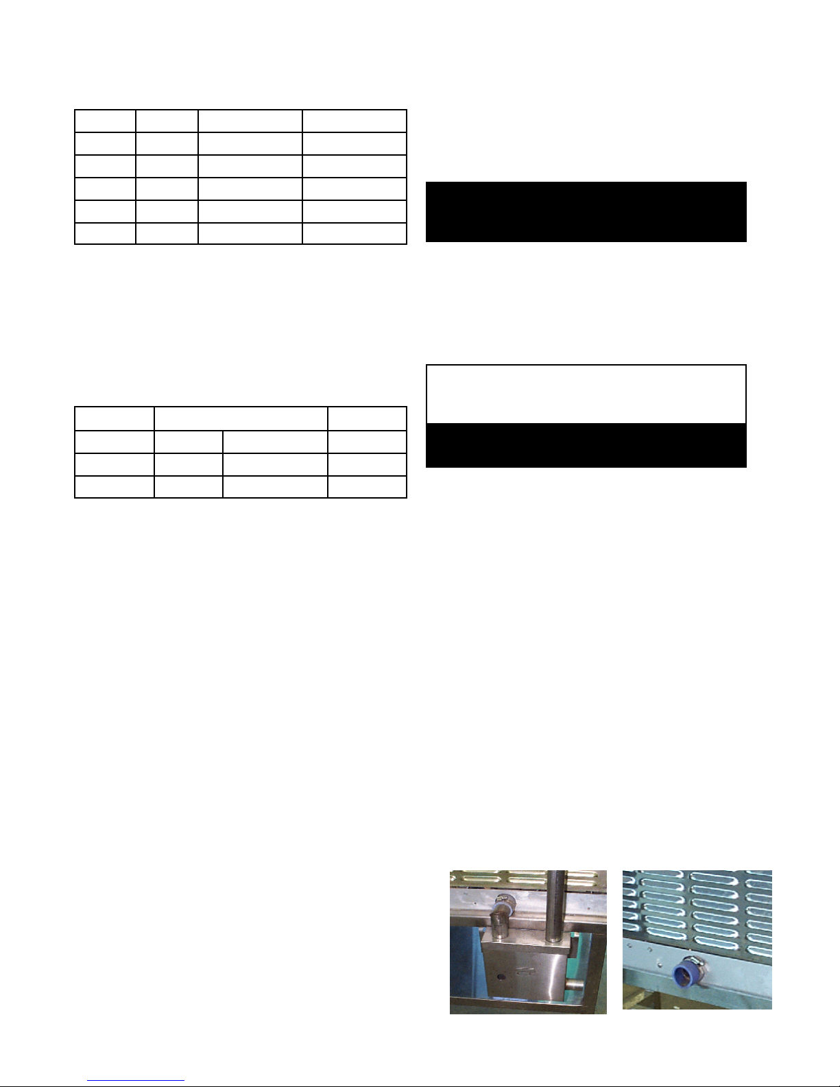
3. Water Supply Connection
A check val ve (back siph onage devi ce) mu st be
installed in th e incoming cold water line in keeping
with local plum bing codes. Wat er li ne pressur e
should be between 30 and 60 PSI ( 210 and 410
kPa). A pressure regulator is requir ed above 60
PSI (410 kPa).
A ¾ inch (19 mm) N H (gar den hose ty pe)
connector is required t o connect t he water supply
to t he wat er inlet valve. The w ater feed line
diameter ma y not be less that ½ inch (13 mm) .
Use a washer (or if necessary, tw o washers) in the
hose connection. Do not allow the connection to
have any leak, no matter how small.
A 1½ inch (4 cm) hose ma y be attached to the
provided dr ain elbow wit h a cla m p. Do not use
plastic pipe. The drain must withstand boiling
water.
WARNING:
DO NO T C O NNECT THE DRAIN DI RE CT LY TO A
BUILDING DRAIN.
There mu st be a free air gap between the end
of th e hose and t he building drain. The free air
gap shou ld be as close as possible t o th e unit’s
drain. There must also be no other elbows or
other restrictions between the unit drain and the
two inch free air gap.
CAUTION
DO NOT USE PL AST IC PIPE. DRAIN MUST BE
RATED FOR BOILING WATER.
WARNING
BLOCKING THE DRAIN IS HAZARDOUS.
Install the drain line with a constant downward
pitch.
IMPORTA NT: Do not allow any water traps in the
li ne. A trap can cause pressure to build up inside
the cavi ty during st eam ing, which will make the
door gasket leak.
NOTE: Improper drain connection will void the w a r ra n ty .
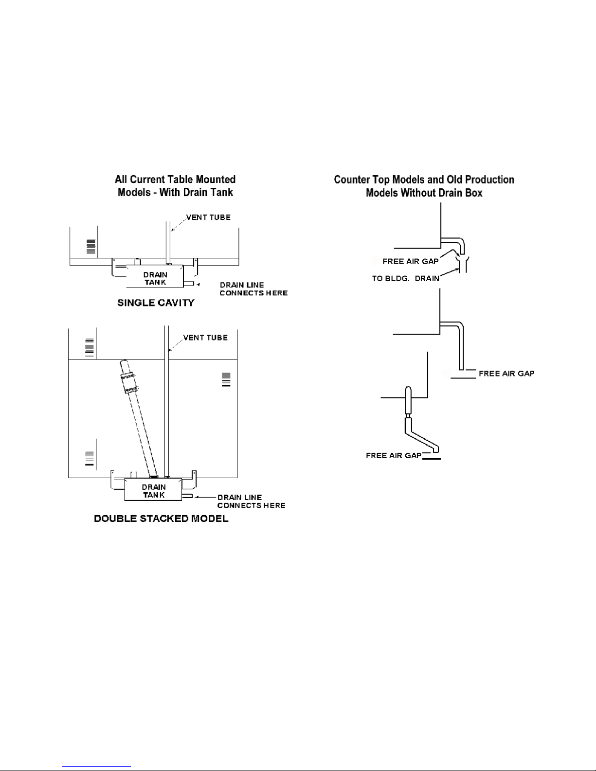
b. CC10-E With Drain Tank
A 1½ inch (4 cm) ID hose may be atta ched to
the supplied dr ain elbow wit h a cla m p. The
hose may be connected directly to a building
drain since the drain tank has an air vent, which
elim inates th e need for a fr ee air gap at the
building drain. Do not block the air vent in any
way. Do not attach anything to the vent tu be or
reduce it s size .
Do NO T use plastic pipe i n the drain line,
because the drain must withstand boiling w a ter.
If you r CC10-E is equipped with the optional split
water su pply, the supply for each steam gen era tor
must be able to fill the generator with 1½ gallons
(5.7 liters) or water in 1½ minutes. The make-up
water rate is 0.06 gall ons per min ute (0.2 lit ers per
minute). Condensate spray water rate is 0.34
gallons per minute (1.3 l iters per minute) at 30 PSI
(210 kPa).
7
Drain Tank
Tabletop Model
Page 8
OM-CC-E
Proper Drain Line Connections
8
Page 9
B.MODEL CC20-E
Mounting
1.
If you wish t o install one Con vection C om bo™
above another , obtain a double-stacked unit from
the fact ory.
CAUTION
DO NOT INS T AL L A CC 20 -E IN AN Y L O CATI ON
WHERE RIGHT SIDE VENTS ARE BLOCKED, OR
WIT HIN 12 INC HE S O F A HEAT S OURCE SUCH
AS A BRAISING PAN, DEEP FRYER, CHAR
BROI LER OR KETTLE.
DO NOT INSTALL THE UNIT TO THE LEFT OF
ANY OPEN FLAME EQU IPMENT.
OM-CC-E
breaker or 10 AWG ( 2.6 mm) for a 40 to 60
amp brea ker.
d. Supply Wire
The type of wir e needed is determined by
fin ding the operating voltage and phase from
the unit’s back data plate and phase select
conn ector. Refer to the “Electrical Supply
Connection” label on the back of the unit for
correct wire size and insulation temperature
rating.
The specified w ire m ust be used to com ply
with U nderwr iters Laboratories and National
Elect ric Code requirements.
To avoid drainage problems, level the unit fron tto-rear , or provide a slight pitch to the rear.
WARNING
THE UNIT MUST BE INSTALLED BY
PERSONNEL QUALIFIED TO WORK WITH
ELECTRICITY AND PLUMBING. IMPROPER
INSTALLATION CAN CAUSE INJURY TO
PERSONNEL AND/OR DAMAGE TO
EQUIPMENT.
CAUTION
INSTALLATION MUST BE IN ACCORDANCE
WITH ALL APPLICABLE CODES.
Elect ri cal Supply Connections
2.
a. Panel Removal
The right si de panel must be removed to gain
access to the w iring and control
compartment. Remove the screw a t th e
back of the panel. Sli de th e panel toward
the front of the u n it, lift it and set it a side.
b. Supply Voltage
The CC20-E must oper ate at th e rated
nameplate voltage, plus or minus 10%.
c. Termi nal block
The terminal block for incom ing power is
located at t he back of t he control
compartment.
The knockout hole i s sized for a one in ch
(25.4 mm) conduit fitting.
CC20-E ELECTRICAL SUPPLY CO NNECTION
(Al l w ires copper only.
Reference: National Electri cal Code)
o
Voltage
208 4 AWG (5.2 m m ) 6 AWG (4.1 m m )
240 4 AWG (5.2 m m ) 6 AWG (4.1 m m )
480 8 AWG (3.3 m m ) 8 AWG (3.3 m m )
e. Branch Circuit Protection
Voltage
Size for 75
(THWN)
Groen strong ly recommends tha t each
Convection Co mbo™ have its own branch
cir cuit protecti on. A double stacked unit
should have separate protecti on for the
upper and lower steam er-ovens.
CURRENT DEMAND
208 65.4 A 21 KW
240 56.7 A 21 KW
480 28.3 A 21 KW
Each current-carrying conductor must have
overcurrent protect ion. Refer to the label on
the back of the unit for pr oper w ire size an d
type. Watertight connections are required.
C
Current per l ine
(Three Phase)
Size for 90oC (THHN)
Power
The ground termina l is fou nd below the
ter m inal block. The Convection Combo™
must h ave a separate ground wir e for safe
operati on. The ground wire must be at least
8 AWG (3.3 m m ) for a 100 am p circuit
W ater Supply Connect ion
3.
A check val ve (back siph onage devi ce) mu st be
installed in th e incoming cold water line in
keeping with local plumbing codes. Water line
pressure should be between 30 and 60 PSI (210
9
Page 10

OM-CC-E
and 410 kP a). A pressure regu lator i s requ ired
above 60 PSI (410 kPa ).
A ¾ inch (19 mm) N H (gar den hose ty pe)
connector is required t o connect t he water supply
to t he wat er inlet valve. The w ater feed line
diameter ma y not be less that ½ inch (13 mm) .
Use a washer (or if necessary, tw o washers) in
the hose connection. Do not allow the
connection to have any leak, no matter how
small.
Drain Connect ion
4.
CAUTION
DO NOT USE PLAST IC PIPE. DRAIN MUST BE
RATED FOR BOILING WATER.
WARNING
BLOCKING THE DRAIN IS HAZARDOUS.
IMPORTA NT: Do not allow any water traps in the
li ne. A trap can cause pressure to build up
insi de the cavity during steam ing, which will
make the door gasket leak.
NOTE: Improper drain connection will void the
warranty.
CC20-E With Drain Tank
A two inch (51 cm) ID hose may be attached to
the supplied dr ain elbow wit h a cla m p. Th e hose
may be connected dir ectly to a building drain
since the drain tank has an air vent, which
elim inates th e need for a fr ee air gap at the
building drain.
Do not block th e air vent in an y w a y . Do not
attach anythin g to the vent or reduce its size.
Do NO T use plastic pipe i n the drain line,
because the drain must withstand boiling w a ter.
10
Page 11

OM-CC-E
Initial Start-Up
WARNING
ANY P OTE NT IAL US ER O F THE EQ UIP M E NT SHO UL D B E TRAIN E D I N SAF E AND C ORRE CT O PE RAT ING
PROCEDURES.
After the Convection Combo™ has been installed,
test it to ensure th at it i s opera ting correctly.
Remove all literature and packing materials from
1.
the interior an d exterior of the unit.
2. Check tha t the cold water supply line is open and
that none of the fittings are leaking.
Turn on electrical service to the unit.
3.
High Altitude Operat ion. At altitudes above
4.
5,000 feet (1524m), the u nit will n ot operate in
the Steamer or Combo Modes unless the altitude
is set. You can program the altitude as follows:
a. If the unit is on, turn it off by pressing the ON
touch pad.
b. Press and hold the STEAM touch pad while
turning the unit on by pressing the ON touch
pad. The Timer Display will show the letters
AL and a number representing the altit ude in
thousands of feet. If the altitude has not
been set for y our unit , the displ ay will be 0.
c. Enter an altitude value between 0 and 15,
usi ng the numbered touch pads. For
example, if the unit will be operating at 7,000
feet, enter 7.
For CC20-E onl y: Check Fan
5.
Rotation — IMPORTANT! As
seen fr om inside the oven cavi ty,
the fan should be turnin g in a
counterclockw ise dir e ction. If the
fan is running backwards
(clockwise), have a qualified
elect rici an turn off th e m ain pow er and switch
any tw o incom ing power lea ds on the di stri bution
block. An incorrectly turn ing fan will eventually
shut the oven down.
Select Farenhei t or
6.
Celsius
Temperatures. The
Convection Com bo™
is delivered w ith the
Farenheit scale as
default. To change
the current
temperature scale,
holding the 5 key in,
press ON. The Tim er
Display will either
show dEG°F or
dEG°C. Press the 5
key again to change
from one to t he other . Press STA RT to a ccept
the change.
d. Press the START touch pad.
Alti tude Metri c C onversion
Altitude
Feet Meters
5000 1524 5
6000 1830 6
7000 2133 7
8000 2438 8
9000 2745 9
10000 3048 10
11000 3353 11
12000 3658 12
13000 3962 13
14000 4267 14
15000 4572 15
Setting
11
To Test S teamer Mode Operation, tu rn on the
7.
unit. ( For details of opera ting procedure, see the
Operation section of this manual.) Clear time
from the time display. Press the STEAM touch
pad. (If the HOT light is on, see the Fast Cool
instructions in th e Opera tion section.)
The WAIT ligh t will stay on while the steam
gen erator fills with a nd heats the water. The
WAIT ligh t should turn off within three minutes,
and the READY light should come on. This
indicates that the water is at its stan dby
temperature. The timer only controls operati ons
in the Steamer Mode. Enter a ti m e and press
START. (“Time” is set in minutes and hours
only. Seconds are not displayed).
Examples: 2 minutes = 00:02
(Just pr ess 2).
1 hour and 30 minutes = 01:30
(Press 1, 3, and 0, or press 9,0
the timer w ill ch ange to 1:30)
Page 12

OM-CC-E
The colon [:] between the numbers on the time
display w ill blink a n d the genera tor will begin to
produce steam. The time will n ot count down
unless the READY light is lit.
NOTE: You cannot change modes i f the timer is
running.
8. To Test C om bo Mode Operation, turn on the
power and clear any t ime from the timer display.
Press the COMBO touch pad. Set the COOK
temperature to 300
will come on. It will rema in on wh ile (1) the
steam generator fills with water and heats it to
its standby temperature and (2) the air heater
raises t he air temperatur e to 300
actions should be completed in about five
minutes, starting with a cold unit. When the set
temperature is att ained, the WAIT light will go
off, and the READY light will come on.
NOTE: The timer does not control the oven in
eit her the C om bo or Oven Modes.
o
F (150oC). The WAIT light
o
F. Both
To Test O ven Mode Operation, turn on the
9.
power and clear the timer display. Press the
OVEN touch pad. Set the cook temperature to
o
F (175oC). The WAIT light will come on.
350
With in six minutes from a cold start, the WAIT
lig ht shou ld go out and the READY light shou ld
come on. When that happens, t urn the COOK
o
temperature setting down to 320
F (160oC). The
HOT light will come on.The heat-up times
provided above may vary sli ghtly as a resu lt of
voltage or wa ter pressure differences.
To shut down the unit, first clear the timer. Next,
10.
press t he mode pad for the mode in wh ich the
unit is oper ating. Finally, switch off the power.
11. If y our Convecti on Combo™ behaves as
descri bed, the u nit is fu nctioning correctly, an d is
ready for use.
12
Page 13

OM-CC-E
Operation
WARNING
ANY P OTE NT IAL US ER O F THE EQ UIP M E NT SHO UL D B E TRAIN E D I N SAF E AND C ORRE CT O PE RAT ING
PROCEDURES.
Controls and Indicators
A.
Operator controls feat ures ar e on the right front si de
of th e unit. Their use is described below:
1. Time Section
In Oven and Combo M odes, the timer
functions only as a “cooking time minute
minder” and does not turn th e unit on or off.
In t he Steamer Mode, h owever, it controls
the steaming function.
a. Displ ay Window — Show s opera ting
ti m e rema ining in the Stea mer, Oven or
Combo Mode. The ti m er counts down.
If the unit is equipped with, and opera ting
in the opti onal H old M ode, the timer will
count up, and will show the total
accumulated t ime that t he product has
been holding. The window shows
operati ng time in “hou rs:minutes” format.
For example, en tering 9 and 0 will result
in a display of 01: 30. (On some older
units numbers higher than 59 will not be
accepted - i n these cases, convert the
time to hours and minutes. 90 minutes
would be entered 1,3, 0.
beeper will sound and the SERVICE light
will be on when you switch on th e power.
The unit may cont inue to operate,
depending on the type of probl em .
Refer t o the Troubleshooting section to
deter m ine the natu re of the probl em .
b. Time t ouch pads — used to enter time
values.
c. CLEAR — Pressing this touch pad once
stops t he beeper an d resets t he timer to
the time tha t was last set. Pressing
twice cl ears it to 00:00. At the en d of a
cooki ng period, opening the door is the
sam e as pressing CLEAR once.
d. START — Press th is touch pad to start
the ti m er. If the unit is in Steam er M ode,
it will also cause steaming to begin.
2. Stat us Lights
a. HOT — Indicates chamber tempera ture
is more than 15
temperature. (See Para graph 5 in this
section)
b. SERVICE — Indicates that there is a
probl em which might require a service
call. If t here is such a problem th e
o
F (8oC) over the set
13
Page 14

OM-CC-E
c. WAIT — Indicates the u n it is either
d. READY — Indicates the unit is ready for
Cooking Mode Select ion
3.
a. STEAM — Selects st eamer operation
b. COMBO — Selects superheated st eam
c. OVEN — Sel ects con vection oven
4. Power
The ON touch pad turns th e unit on or off.
When power is on, the ON light just above
the touch pad is lit. U se of t his pad does n ot
reset the con trols. The unit will always come
on in the same mode it was in when shut
down.
heating or cooli ng toward the set
temperature. The HOT and WAIT lights
will both be on if the chamber is more
than 15
o
F (8oC) above the set point.
use.
only.
and con vection oven operation.
operati on only .
5. Temperature (TEMP) Section
a. The Tempera ture Display Win dow shows
the select ed temperatur e in either Oven
or Combo Mode. It is bl ank i n the
Steamer Mode or when th e optional Hold
Mode is operational.
b. Turning the Temperatu re Control Knob
select s the cooking tem peratu res in 5
increments. The control ranges a re:
o
Oven Mode 200-575
Combo Mode 220-575
Optional HOLD Section
6.
F (95- 300oC)
o
F (105- 300oC)
This optional feature permits l ow
temperature holding or (on m odels built
before November 1996) proofin g with
controlled humidity, when the unit has
already been set in the O ven or Combo
Mode. Whet her Oven or Combo Mode has
been selected has no effect on this optional
feat ure’s operation. H old M ode controls are
located at t he bottom of the control panel.
o
F
a. The upper window shows the sel ected
holding temperature. This display is
blank w hen th e Hold Mode has been
turned off.
14
Page 15

b. Turning the Hold Cont rol Knob clockw ise
activates the H old M ode and sets
temperatures in 5
range of 90
o
The OVEN or COMBO mode light m ust
be on befor e Hold Mode can opera te.
c. On units with the Hold Option which
were manufactured before November
1996, t here is a lower w indow which
displays the selected humidity. If the
Hold M ode is turned off, it will be blank.
d. Pressi ng the hum idit y set touch pad on
these units selects the relative humidity
Available choices for hum idity setti ngs
are LO; 45, 50, 55, 60, 65, 70, or 80%;
and HI.
Operati ng Instructio ns
B.
1. Steamer Mode
a. If the unit is off, switch on the electric
power by pressing the ON touch pad. (If
the SERVICE light comes on when you
turn on the power, see the
Troubleshooti ng section).
o
F increments within a
F to 200oF (30 t o 95oC).
OM-CC-E
WARNING
WHEN YOU OPEN THE DO OR STAY AWAY
FROM ANY STEAM COMI NG OUT OF THE
UNIT. STEAM CAN CAUSE BURNS.
e. The WAIT ligh t will be on un til th e water
reaches 200
off a nd the READY light will come on.
You are n o w ready to st eam foods in
your Convection Combo™.
f. Load the food in to pans in a n even,
o
F (93oC). It w ill th en turn
b. If the power is already on, an d th ere is a
number in the time display window,
press t he CLEAR t ouch pad one or more
times to reset the time to zero.
NOTE: You cannot change operating
modes w hile the ti m er is running
c. The unit will power up in th e mode of
operati on in which it was la st used.
Because of this, the indicator light for
that mode w ill be lit. If the unit is not
already in the S team er M ode, press the
STEAM touch pad. The STEAM light
will come on and the Temperature
Window will go blank.
d. If the unit was recentl y used in O ven or
Combo Mode, t he HOT li ght may come
on, indicati ng that t he cookin g chamber
is too hot for use as a steamer. The unit
can be cooled quickly to the steam ing
temperature range by leav ing the door
open or following the Fast Cool
procedure described near the end of this
secti on (Par agraph 5). With the door
open the generator can fill a n d heat the
water to 200
o
F, but it cannot produce
steam.
uniform layer.
g. Carefully open the door and slide the
pan or pan s onto the pan ra cks in the
cooki ng chamber. If y ou are on ly using
one pan , place it in the m iddle posi tion.
Close t he door.
h. Press the nu m bered touch pads to set
the cooking time. The time will appear in
the Time Display Window . If you enter
the wron g number, press the CLEAR
touch pad to erase the time from the
display, an d enter the time again.
i. When the correct cooking time has been
entered, press the START pad. The
colon in th e display w ill blink a n d the time
will count down the cooking time. (The
unit must be READY before the ti m er
can count down.
j. If you open the door during the cooking
period, steaming and the timer will stop
(but will not reset). When y ou close the
door, steam in g and tim ing will continue.
15
Page 16

OM-CC-E
WARNING
WHEN YOU OPEN THE DOOR STAY AWAY
FROM ANY S TE AM C O MING O UT O F T HE UNIT.
STEAM CAN CAUSE BURNS.
number keys when you first use set that
time.
n. After the display has counted down to
zero you can reset the time to zero by
eit her (1) opening the door and pressing
CLEAR or pressing CLEAR twice. A
new cookin g time m ay th en be set by
usi ng the number keys.
2. Oven Mode
a. To use the Convection Combo™ as a
conv ection oven, first switch on the
elect ric power by pu shing the ON touch
pad. (If the SERVICE light comes on
when you turn on the power, see the
Troubleshooti ng section). If the door is
closed and the cooking tem perature is
above 200
o
F (93oC) the fan w ill begin to
operate.
b. If the power is already on, an d th ere is a
number in the time display window,
press t he CLEAR t ouch pad one or more
times to reset the time to zero.
Wh en the timer reaches zero, it stops steam
k.
generation and sounds a beeper alarm . Water in
the steam gen era tor stays at its stan dby
temperature (200
o
F - 93oC). On some older
models, the beeper will continue to sound until
the door i s opened or the CLEAR pad i s
pressed.
l. Careful ly open the door. If th e food i s
cooked, remove the pa ns using hot pads
or oven mitts to protect your hands from
the hot pans.
m. After the display h as counted dow n to
zero opening the door or pressing
CLEAR once
will reset the display to the
time that was last used. Pressing
START will repeat the cook cycle. If the
NOTE: You cannot change operating
modes w hile the ti m er is running
c. The unit will power up in th e mode of
operati on in which it was la st used.
Because of this, the indicator light for
that mode w ill be lit. If the unit is not
already in the O ven Mode, press t he
OVEN touch pad. The OVEN light will
come on and the oven fan will operate.
d. Use the Tem perature Con trol Knob to
set t he desired cooking temperatur e,
which will appear in th e temperature
displ ay wi ndow. Unless the cookin g
chamber is already at or above the
selected temperatu re, the unit will begin
heating and the WAIT ligh t will come on.
same cooking time will be used
repeatedl y, you only n eed to press the
16
Page 17

e. If the unit was recently used at a
temperature more than 15
o
F (8oC) higher
than the temperature selected, the HOT
and WAIT lights will turn on. The unit can
be cooled quick ly to the desired cooking
temperature by leaving the door open or
following the Fast Cool procedure
descri bed near t he end of this secti on
(Paragraph 5).
f. The READY light will indicate when the
oven is at the desired t em peratu re.
OM-CC-E
k.
To stop cooking, t ake th e pans out of the
oven using hot pads or oven mit ts to
protect your hands from the hot pans.
The unit will con tin u e heating to keep th e
chamber at the set temperature until the
temperature control is r eset, or the pow er
is shut off.
g. Load the food i nto the pan or pa ns in a
uniform layer.
h. The Convection Combo™ will operate i n
Oven Mode with the timer either on or off.
If you wan t to time the cooking, press th e
number ed pads in the TIM E portion of t he
control panel to set the cooking time. The
time will appear in the Time Display
Window. If you enter the wrong number,
press t he CLEAR t ouch pad t o erase the
time from the display, and enter the time
again. Remember that the timer does not
control the unit in the O ven Mode.
i. Open the door a nd slide the pan or pan s
onto the pan rack s in the cooking ch amber.
If you are only u sing one pa n, place it i n
the middle posit ion. Close the door.
j. If the correct ti m e has been set on the
timer, press the START pad. The colon [:]
between the numbers in the display will
blink and the time will count down the
cooking time. When the timer ha s counted
dow n to zero, it will sou n d a beeper . This
sou n d will continue until the door i s opened
or t he CLEAR pad is pr essed.
WARNING
PANS AND INTERNAL PARTS OF THE OVEN
WILL BE VERY HOT. AVOID CONTACT WITH
HOT SURFACES.
l. Opening the door du ring operation shu ts
off power to the heaters and fan and
stops the timer, but it has no other affect
on the controls. When the door is cl osed,
operati on conti nues. Note t hat cook in g
time will be extended by the period the
door was open.
3. Combo Mode
a. If the unit is off, switch on the electric
power by pressing the ON touch pad. (If
the SERVICE light comes on when you
turn on the power, see the
Troubleshooti ng section). If the door is
closed and the cooking tem perature is
above 200
o
F (93oC) the fan w ill begin to
operate.
b. If the power is already on, an d th ere is a
number in the time display window, pr ess
the CLEAR tou ch pad one or m ore times
to reset the time to zero.
17
NOTE: You cannot change operating
modes w hile the ti m er is running
c. The unit will power up in th e mode of
operati on in which it was la st used.
Because of this, the indicator light for that
mode w ill be lit. If the unit is not already
in the Combo Mode, press the COMBO
touch pad. The COMBO light will come
on an d if th e stea m generat or is not
already fu ll, w a ter will flow into it and
begin heating.
d. Use the Tem perature Con trol Knob to set
the desir ed oven temper ature betw een
220 and 575
o
F (105 t o 300oC). The
temperature will appear in the
temperature displ ay window.
Page 18

OM-CC-E
e. If the unit was recently used at a
temperature more than 15
than the temperature selected, the HOT
and WAIT lights will turn on. The unit can
be cooled quick ly by leaving th e door open
or followin g the Fast Cool procedure
descri bed near t he end of this secti on
(Paragraph 5).
WARNING
WHEN YOU OPEN THE DOOR STAY AWAY
FROM ANY ST EAM CO MING O UT O F T HE UNIT.
STEAM CAN CAUSE BURNS.
f. The WAIT light will be on u n til th e wa ter in
the steam generator reaches the boiling
point and the air in the cooking chamber
reaches the set temperatu re. It will then
turn off and the READY light will come on
indicati ng tha t the oven is at th e desired
temperature.
o
F (-8oC) higher
i. Open the door a nd slide the pan or pan s
onto the pan racks in the cooking
chamber . If you are only usin g one pan,
place it in the m iddle posi tion. Close the
door.
j. If the timer h as been set, press the
START pad. The colon [:] between the
numbers in th e display w ill blink a n d the
time will count down the cooking time.
When the timer has count ed down to
zero, it will sound a beeper . This beeping
will continue until the door is opened or
the CLEAR pad i s pressed.
k. To stop cooking, take the pans out of t he
oven using hot pads or oven mit ts to
protect your hands from the hot pans.
The unit will con tin u e steaming and
heating the oven at the set temperatu re
until the temperature control is reset, or
the power is shut off.
Hold Mode (Cook-n-Hold Option) - (Cook-n-
4.
Hold/Proof ing Option on Models Manu-
g. The unit w ill operate in Combo Mode w ith
the timer either on or off. If you w a n t to
ti m e the cooking, press the n umbered
pads in the TIME portion of the control
panel to set the cooking time. The time
will appear i n the Tim e D isplay Window . If
you enter the wrong num ber, press the
CLEAR touch pad to era se the time fr om
the display, and enter the time again. The
timer does not control the unit in Combo
Mode.
h. Load the food i nto the pan or pa ns in a
uniform layer.
WARNING
WHEN YOU OPEN THE DOOR STAY AWAY F ROM
ANY STEAM COMING OUT OF T HE UNIT . STEAM
CAN CAUSE BURNS.
fact ured Before Novem ber 1996) Items
identi fi ed by an asterisk (*) and/or in italics per tain
to Hum idity Control features on some model s
manufactured prior to November 1996.
18
Page 19

a. If these optiona l feat ures ar e included in
your Convection Combo,™ the controls are
located near the bottom of the Control
Panel. Hold M ode m ay be act ivated when
the oven is ei th er in Combo or O ven Mode,
and works the same in both.
b. If you want your Convection Combo™ to
switch to Hold Mode automa tically when i t
fin ishes cooking, use the foll owing
procedure:
1) Set the unit for Combo or Oven Mode.
2) Set COOK tem peratu re.
OM-CC-E
NOTE: Food will continue to be cooked
by the excess heat as the unit
slow s to the set HOLD
temperature. The am ount of
additi onal cook ing depends on
the food produ ct a nd the initial
COOK temperature.
The oven will opera te at the set HOLD
temperature (and humidity)* u n til it is
chan ged or turned off. If desir ed, you
may check t he time on hold by pressing
START. The u n it w ill count up and
displ ay th e time elapsed since it has been
holding. The maximum that the timer is
able to display is 19 hours and 59
minutes. After that the display will flash
19:59, but the unit will continue to
maintain the HOLD settings.
c. To end manual operation of the Hold
Mode, fir st remove the food from t he uni t.
Then take either of t he following steps:
1) If the timer is not running, turn the
COOK temperature set knob
clockwise until a number appears i n
the COOK temperatur e display. (The
unit will h eat to the COOK setting).
2) If the timer is running, press and hold
in the CLEAR touch pad for at least
two second s.
3) Set the cooking time.
4) Turn the HOLD temper ature set knob
until t he desired hold temperatu re
appears in the HOLD temperature
display.
5) (Press HUMIDITY set touch pad unt il
the desired setting appear s in t he
HUM IDITY displ ay).*
6) After the READY light comes on to
indicate the oven is at the set
temperature, open the door, load food
into t he uni t a nd close the door.
7) Press the START touch pad.
When the set cook time is ended, the unit
will automatically switch to the H old Mode.
The beeper will NOT sound. The timer
will now count UP. The COOK
temperature display w ill be blank and the
temperature of the unit w ill slowly drop to
the HOLD temperature setting.
19
Page 20

OM-CC-E
5. Fast Cool
Shutt ing Down
6.
a. When the HOT indicator is lit and the
ti m er is cl eared, the uni t can be cooled
quickl y by openi ng the door and
pressing START. The fan will
operate, and th e TIME window will
display the word “COOL.” This is the
only time t he fan opera tes with the
door open.
WARNING
DO NOT PUT HANDS OR OTHER OBJECTS
INTO THE COOKING CHAMBER DURING THE
FAS T C OO L OP ERATIO N. T HE RO T AT ING FAN
CAN BE HAZARDOUS.
b. To stop t he Fast Cool operation, press
any tou ch pad or close the door.
a. Press the touch pa d for the mode in w hich
the unit is oper ating.
b. Switch off th e power by pr essing the ON
touch pad.
Leave the door at least partially open, if local
sanitation regulations permit.
20
Page 21

OM-CC-E
Cleaning
To keep your Con vection C om bo™ in proper opera ting condition an d to ma ke the cleanin g process ea sier, clea ning
should be a daily activity.
Suggested Tools and Cl eaners
A.
1. Mild det ergent
2. Stainless steel exterior cleaner such as
Zepper®
3. Steam gen erator de-li m ing agent, such as
Groen Deli m er Descaler, Lime-Away®
or an equivalent. A liquid de- liming agent
will be easier to use than crystals or
powders. See the warning about chlorides
below.
4. De-greaser, such as EncompasS®, Malone
34®, Puritan P uribrute® , or Con-Lie®
5. Clot h or sponge
Plasti c wool or a brush wit h soft bri stles
6.
Spra y bottle
7.
8. Measuring cup
9. Nylon pa d
10. Towels
Plasti c disposable gloves
11.
Procedure
B.
1. Exterior Cleaning
a. Prepare a w arm solu tion of the mild
deter gent as instru cted by the supplier. Wet
a cloth with this solution and wring it out.
Use the m oist cl oth to clean the outside of
the unit. Do not allow freely running liquid to
touch the controls, the control panel, any
elect rical part, or any open louver.
To remove material which may be stu ck to
b.
the unit, use plasti c wool, a fiber br ush, or
a plastic or ru bber scraper with a
deter gent solution.
Stainless steel surfaces may be polished
c.
with a recognized sta inless steel clea ner
such a s Zepper®.
DISCONNECT THE POWER SUPPLY
BEFORE CLEANING THE OUTSIDE OF
THE UNIT.
KEEP WATER AND CLEANING
SOLUTIONS OUT OF CONTROLS AND
ELECTRICAL COMPONEN TS. NEVER
HOSE OR STEAM CLEAN ANY PART
OF THE UNIT.
DON’ T MIX DE-LIMIN G AGENTS (ACID)
WITH DE-GREA SERS (ALKA LI)
ANYWHERE IN THE U NIT
AVOID CONTACT WITH ANY
CLEANERS, DE-LIMING AGENT OR DEGREASER AS RECOMMENDED BY THE
SUPPLIER. MANY ARE HARMFUL.
READ THE WARNINGS AND FOLLOW
THE DIR ECTIONS!
EVEN WHEN THE UN IT HAS BEEN
SHUT OFF, DON’T PUT HANDS OR
TOOLS I NTO THE COOKIN G
CHAMBER UNTIL THE FAN HAS
STOPPED TURNING.
DON’T USE ANY CLEANING OR DELIMING AGENT THAT CONTAINS ANY
SULFAMIC AGENT OR ANY CHLORIDE,
INCLUDING HYDROCHLORIC ACID
(HCl). TO CHECK FOR CHLORIDE
CONTENT SEE ANY MATERIAL
SAFETY DATA SHEETS PROVIDED BY
THE CLEANING AGENT
MANUFACTURER.
UNIT MA Y BE HOT. TA KE
PRECAUTIONS TO PREVEN T
CONTACT WITH HOT SURFACES.
PRECAUTIONS
WARNING
DO NOT USE ANY METAL MATERIAL (SUCH AS METAL SPONGES) OR METAL IMPLEMENTS (SUCH AS
A SPOON, SCRAPER OR WIRE BRUSH ) THAT MIGHT SCRATCH THE SURFACE. SCRATCHES M AKE THE
SURFACE HARD TO CLEAN AND PROVIDE PLACES FOR BACTERIA TO GROW. DO N O T USE STEEL
WOOL, WHICH MAY LEAVE PARTICLES IMBEDDED IN THE SURFACE WHICH COULD EVENTUALLY
CAUSE CORROSION AND PITTIN G.
IMPORTANT
21
Page 22

OM-CC-E
Interior Cleaning
2.
To exit the Clean Cycle at any time, press and
hold the CLEAR touch pad. Be sure to wash
out al l chemical residues t horoughly before
using t he unit.
UNIT MAY BE HOT. DO NOT TOUCH HOT
SURFACES.
DO NOT PUT HANDS OR OTHER OBJECTS
IN TO COOKING CH AMBER WHILE CONVECTION
CO MB O ™ IS OPE RATING. THE RO TATING F AN
CAN BE HAZARDOUS.
a. Turn off a ll operating modes by stopping the
ti m er, an d pressing the mode t ouch pad( s).
b. Enter 99 on the timer. The display should
show “00:99.”
c. If the HOT light is on, use the Fast Cool
method to reduce the temperatur e
(Paragraph 5, Oper ation, Page 18). If the
HOT light is off, “CI” will be displayed in th e
ti m er w indow, an d you may proceed to the
next step.
Remove all pan racks and clean them in a
d.
sink. To remove the right side rack, lift it up
and to the left.
Remov e the right side of th e cooking
e.
chamber.
Prepare oven degreaser a s direct ed on the
f.
product l abel. Thorou ghly coat a ll i nside
surfaces of the cookin g chamber and both
sides of the right side pan el with the
degreaser.
WARNING
It ma y cause the unit to display false service
messages.
Replace the generator cover an d right side
i.
panel in their normal positions.
Close t he door and press START. The timer
j.
will display “CL:50,” with the colon [:]
between the numbers flashin g. The timer w ill
count down to “CL:26.”
k. When the buzzer sounds and the timer
displays “C2,” open the door.
WARNING
THE UNIT WILL BE HOT ENOUGH TO CAUSE A
BURN. DO NOT TOUCH ANY HOT SURFACE.
l. Remov e the right side panel an d steam
generator cover an d rinse them in the sink.
l. Rinse and wipe down the cooking ch amber
with a cloth and plenty of clean wa ter. Rinse
the clot h often.
n. Add de-l iming agent to the steam generator
as speci fied by the de-li m ing agent label.
o. Put the genera tor cover an d right si de panel
back in place.
p. Close t he door. The timer w ill display
“CL:26" and count down automatically to
“CL:00.”
q. Press the ON switch to turn off the u n it. Let
the unit cool.
Remov e the steam generat or cover.
g.
NOTE:
h. If there are grease deposits in the genera tor,
Add degreaser to the steam gen erator
only if you see grease deposit s.
add ¼ to ½ cup (60 t o 125 m l) of fu ll
str ength degr easer to the genera tor, or
lig htly coat the generator w ith spray
degreaser. Do not use too mu ch degreaser .
22
WARNING
UNIT MAY BE HOT. DO NOT TOUCH HOT
SURFACES.
Remov e the right side panel an d steam
r.
generator cover and rinse them thoroughly in
a sink.
Page 23

Rinse and wipe down the cooking ch amber
s.
with a cloth and plenty of clean wa ter. Rinse
the clot h often.
3. De-liming Only
If you only w ant t o clean har d, w hite deposits out of
the steam gen era tor, it is not necessary t o degrease
the unit.
a. Turn off a ll operating modes by stopping the
ti m er, an d pressing the mode t ouch pad( s).
Enter 99 on the timer. The display should
b.
show “00:99.”
c. If the HOT light is on, use the Fast Cool
method to reduce the temperatur e
(Paragraph 5, Oper ation, Page 18). If the
HOT light is off, “CI” will be displayed in th e
ti m er w indow, an d you may proceed to the
next step.
OM-CC-E
Press the ON switch to turn off the unit. Let
k.
the unit cool.
WARNING
UNIT MAY BE HOT. DO NOT TOUCH HOT
SURFACES.
l. Remov e the right side panel an d steam
generator cover and rinse them thoroughly in
a sink.
m. Rinse and wipe down the cooking chamber
with a cloth and plenty of clean wa ter. Rinse
the clot h often.
n. Re-install the pan racks.
d. Remove all pan racks and clean them in a
sink. To remove the right side rack, lift it up
and to the left.
Pour one pint (two pints for CC-20E) de-
e.
lim ing agent into th e steam generator.
Close t he door and press START. The timer
f.
will display “CL:50,” with the colon [:]
between the numbers flashin g. The timer w ill
count down to “CL:26.”
WARNING
THE UNIT WILL BE HOT ENOUGH TO CAUSE A
BURN. DO NOT TOUCH ANY HOT SURFACE.
g. When the buzzer sounds and the timer
displays “C2,” open the door AND CH EC K
THE STEAM GENERATOR.
NOTE: If the timer stops and the SERVICE light
comes on, it mea ns tha t there have been
errors that prevent the unit from completing
it s Clea n Cycle. Take the following st eps:
1) Perform a reset. With the unit turned off,
press and hold the COMBO touch pad.
Then press the ON touch pad to display any
err or codes.
If the error numbers displayed ar e 1 and 3,
2)
or 2 and 3, press CLEAR, and restart the
Clean C ycle by entering “99" (00:99) on the
ti m er. Add one cup of full strength
degreaser and continue the Cl ean Cycle by
pressing START.
3) If the error numbers ar e 1 and 2, or 6, call
your auth orized Groen Service A gency for
immediate service.
If the error number displayed is 1 or 2, but
4)
not both, t he unit may need more cleaning.
If there are other errors, refer to this manual’s
Troubleshooti ng Section (Page 24)
h. If the generator is fr ee of hard deposits, go
to t he next step. If h ard, w hite deposits are
still visible, add de-liming agent a gain before
proceeding.
i. Put the genera tor cover an d right side panel
back in place.
j. Close t he door. The timer w ill display
“CL:26" and count down automatically to
“CL:00.”
Clean Cycle Counter
The Convection Combo™ keeps track of
completed Clean Cycles. To see this total, turn
off the unit. Press and hold the 0 touch pad while
turning on the unit. The total will show in the
timer window. It cannot be reset.
3. Manual Cleani ng
This procedure may be necessary if r egular cleaning
was not per for m ed.
23
Page 24

OM-CC-E
NOTE:
DO NOT PUT HANDS OR OTHER OBJECTS
INTO THE COOK ING CHAMB E R WHILE THE FAN
IS TURNING.
It is strongly recom m ended tha t the u nit be
run through a Clean Cycle after manual
cleaning. Repea t a s necessary .
WARNING
1. If the unit has been oper ating in the O ven or
Combo Mode, all ow it to cool or use the
Fast Cool procedure descri bed in the
Operations Section (Page 18).
Maintenance
When the unit has cooled en ough to be
2.
cleaned, sw itch it off by pressing th e ON
touch pad.
3. Remov e the right side panel fr om th e cooking
chamber.
®
Using Easy-Off
4.
comparable product, thoroughly coat all
inside surfaces of th e chamber, in cluding the
right side panel. Follow the manufacturer’s
instr uction s on the cleanin g agent label.
5. Inst all the right side panel.
Rinse and wipe down the cooking ch amber
6.
with a cloth and plenty of clean wa ter. Rinse
the clot h often.
Oven Clean er or a
The Groen C onvection Combo™ is designed for
minimum maintenance. Certain parts may need
repl acement after prolonged use. If th ere is a need
for service, only Groen person nel or author ized
Groen representa tives should perform the work.
Always supply water with a low mineral count that
meets the standards outl ined in the Water
Conditioning section of this manual.
If steam or con densate is seen leak ing from arou nd
the door, ta ke the following steps:
Check the door gasket. R eplace if it is cracked
1.
or spl it. Inspect the cooking ch amber drain to be
sure it is not blocked.
Troubleshooting
Resetti ng the Solid S t at e Controls
A.
(I f problems persist call an authorized Groen
Service Agency)
If the controls stop responding to norm al
operati ons, or the unit is behaving oddly, reset
the control s using the following procedure:
1. Switch off th e power by pr essing the ON
touch pad.
2. While pressi ng the COMBO touch pad,
switch the pow er back on. If no errors are
present the unit will beep and show four
zeroes in the displ ay. If there are er rors, the
unit will not beep, but will display Serv ice
Codes, i n the t imer and cook tempera ture
displ ays. N ote the Service Codes. Press
CLEAR to exit Service Mode and refer to t he
following explanation of service messages.
Adjust the latch pin as follows:
2.
a. Loosen the lock nut a t the base of the latch
pin, and turn the latch pin ¼ turn clockwise.
Re-tighten the lock nut.
b. After adjustment, run the unit to test for
further steam leak s.
c. If there is still leakage, repeat th e
adjustment.
d. Continu e adjusting the pin clockwise un til the
door fits ti ghtly enough t o prevent leaks.
Service Messages
B.
There are two types of service message:
1. Non-critical er ror: signaled by three quick
beeps. The SERVICE ligh t comes on for 15
seconds and th en goes out.
Critical error: signaled by a continuous five
2.
second beep. The SERVICE comes on and
stays on.
If there is a non-critical error you may continue to
operate t he uni t. When possi ble, i nspect th e Service
Code. Turn off th e unit by pressing the ON touch
pad. While pressing the COMBO touch pad, switch
the power ba ck on . N ote the numbers and refer to
the Troubleshooti ng Guide which fol low s. Press
CLEAR to exit the Service Mode. If ther e is a crit ical
error, the un it will not opera te in it s curren t mode, but
may operate in another. Inspect the Service Code
as described above, and call your a uthor ized Groen
Service Agency.
24
Page 25

OM-CC-E
Troubleshooting Guide
If a problem persists after t akin g the actions suggested below , ca ll your author ized Groen serv ice representative.
CODE IN DICATES SUGGESTED ACTION
Try cleaning steam generator to remov e contami nation from the probes.
1 Low water l evel probe
2 High water level probe
Maximum generator fi ll
3
ti m e (90 secon ds) has
been exceeded.
4 Faulty air probe
5*
7*
7A*
*Service Code 5 is not used on units manufactured after March 1, 1997. Service Code 7 indicates Out of
Calibration for units m ade before March 1, 1997. Th ereafter i t indicates Time Between Fills, descri bed in 7A ,
above. These ch anges wer e m ade on units aft er Serial Number C7439MS .
Faulty drain probe
(Units Befor e 3/97 On ly)
6 Fau lty generator probe
Out of Calibration
(Units Befor e 3/97 On ly)
Time Between Fills
(Units After 3/97 Only)
Maximum generator drain
8
time (five minutes) has
been exceeded.
If either code continues call your Gr oen Servi ce Agency.
•
If both codes are displayed the unit will only operate in the Ov en Mode.
•
If only on e code is displ ayed th e unit will operat e in all modes, but water
•
may overflow from the generator into the cooking ch amber dur ing
operati ons in either the Steam or Combo M odes.
Make sure the water supply is fully turned on and that hoses are not kinked
or pi nched.
If the code is still displayed the unit w ill operate in the Ov en Mode onl y.
•
Call your Groen Servi ce Agency
•
• The un it will operate i n Steamer and Clean C ycle Modes only .
• Call your Gr oen Service Agency
The unit will operate i n all m odes.
•
Call your Groen Servi ce Agency
•
• The un it will operate i n Oven Mode only .
• Call your Gr oen Service Agency
The unit will operate i n all m odes.
•
Call your Groen Servi ce Agency
•
Check for a leaky fill valve.
The unit will operate i n Oven Mode only .
•
Call your Groen Servi ce Agency
•
Inspect the drain line and remove any blockage. Make certain that the
drain is free-vented as detailed in the Installation Section of this Manual.
(Paragraph 4, Pa ge 6)
Mode Operation — After a Service Code Occurs
Mode
Steam Yes Yes No Yes Yes NA No Yes No No No
Combo YesYesNoNoYesNANoYesNoNoNo
Oven Yes Yes Yes No Yes NA Yes Yes Yes Yes Yes
Clean Yes Yes No Yes Yes NA No Yes No No No
*Service Code 5 is not used on units manufactured after March 1, 1997. Service Code 7 indicates Out of
Calibration for units m ade before March 1, 1997. Th ereafter i t indicates Time Between Fills. These cha nges
were ma de on uni ts after Ser ial N umber C7439MS.
12345* 5A 6 7* 7A 8 1 & 2
Service Code
25
Page 26

OM-CC-E
Diagrams & Schem atics
CC10-E Control Schematic
CC10-E Heater S chematic
26
Page 27

Diagrams & Schem atics, Continued
OM-CC-E
CC20-E Co ntrol Schematic, 208/240 Volt s
CC20-E Co ntrol Schematic 480 Vo lts
27
Page 28

OM-CC-E
Diagrams & Schem atics, Continued
CC20-E Heater S chematic, 208/ 240 V olts
CC20-E Heater S chematic, 480 Volts
28
Page 29

Diagrams & Schem atics, Continued
OM-CC-E
CC20-E Heater S chematic 208/240 Volts
(Units That Meet Canadian Standards Association Requirements)
29
Page 30

OM-CC-E
Service L o g
Model No.
Serial No.
Date Purchased
Purchase Order No.
Date Maintenance Performed Performed by
Purchased From
Location
Date Installed
For Service Call
30
Page 31

OM-CC-E
LIMITED WARRANTY TO
COMMERCIAL PURCHASERS*
(Continental U.S., Hawaii and Canadian Sales Only)
Groen Foodservice Equipment (“Groen Equ ipmen t”) has been skillfu lly manufactured, carefully inspected, and
packaged to meet rigi d sta ndards of excellence. Groen warrants its Equipment to be free from defects in ma terial
and workmanship for (12) twelve months with the following conditions an subject to the following limitations.
I. This parts and labor w arranty is limited t o G roen Equipment sold to the origi nal commercial
purchaser/users (but not original equipment manufacturers {O.E.M.}), at its original place of installation in
the continental United States, Hawaii and Canada.
II. Dam age during shipment i s to be reported to the carrier, is not covered under th is warra nty, and is the sole
responsibility of the purchaser/user.
III. Gr o e n,, o r an aut horized service r e p resentativ e , will repair or replace, at Groen’s sole election, any Groen
equipmen t, i ncluding but not l imited to, draw -off valv es, sa fet y val ves, gas a nd electric compon ents, found
to be defective during the warr anty period. As to wa rran ty service in the terri tory described above, Groen
will absorb labor and portal to portal transportation costs (time and mileage) for the first twelve (12)
month s fr om date of installati on or fifteen (15) months from date of shipme nt from Groen.
IV. This warranty does not cover boiler main tenance, calibration, periodic adjustments as specified in
operati ng inst ructions or m anuals, and consumable parts such as scraper blades, gaskets, packing, etc.,
or l abor costs incu rred for removal of adj acent equ ipment or objects to gain access to Groen E quipment .
This warranty does not cover defects caused by i m proper installati on, abuse, carel ess opera tion, or
improper maintenance of equipment. This warranty does not cover dama ge caused by poor water quality
or i m proper boiler m aintenance.
V. THIS WARRANTY IS EXCLUSIVE AND IS IN LIEU OF ALL OTHER WARRANTIES, EXPRESS OR
IMPLIED, INCLUDING ANY IMPLIED WARRANTY OF MERCHANTABILITY OR FITNESS FOR A
PARTICULAR PURPOSE, EACH OF WHICH IS HEREBY EXPRESSLY DI SCLAIMED. THE REMEDIES
DESCRIBED ABOVE ARE EXCLUSIVE AND IN N O EVENT SHALL GROEN BE LIABLE FO R SPECIAL,
CONSEQUENTIAL OR INCIDENTAL DAMAGES FOR THE BREACH OR DELAY IN PERFORMANCE
OF THIS WARRANTY.
VI. Groen Equipment is for commercial use only. If sold as a component of another (O.E.M.) Manufacturer’s
equ ipment, or if used as a consumer product, such Equipment is sold AS IS a n d without an y warranty.
*(Covers all Foodservice Equipment Ordered after Oct ober 1, 1995)
31
Page 32

1055 Mendell Davis Drive OM-CC-E (Revised 7/00)
Jackson, MS 39212 Part Number 121015 Rev. A
Telephone 601 372-3903
Fax 601 373-9587
 Loading...