

Groen CC10-G, C/2-20G, CONVECTION COMBO 2CC10-G, CONVECTION COMBO 2C/2-20G, CONVECTION COMBO CC10-G Operator's Manual
...Page 1
• •
• •IMPORTANT INFORMATION
IMPORTANT INFORMATION • •
• •• •
IMPORTANT INFORMATION IMPORTANT INFORMATION
• • KEEP FOR OPERATOR
KEEP FOR OPERATOR • •
• •• •
KEEP FOR OPERATOR KEEP FOR OPERATOR
• • IMPORTANT INFORMATION
IMPORTANT INFORMATION • •
• •• •
IMPORTANT INFORMATION IMPORTANT INFORMATION
• •
• •• •
OPERATOR MANUAL OM-CC-G and C/2-G
Part Number 121086 DOMESTIC
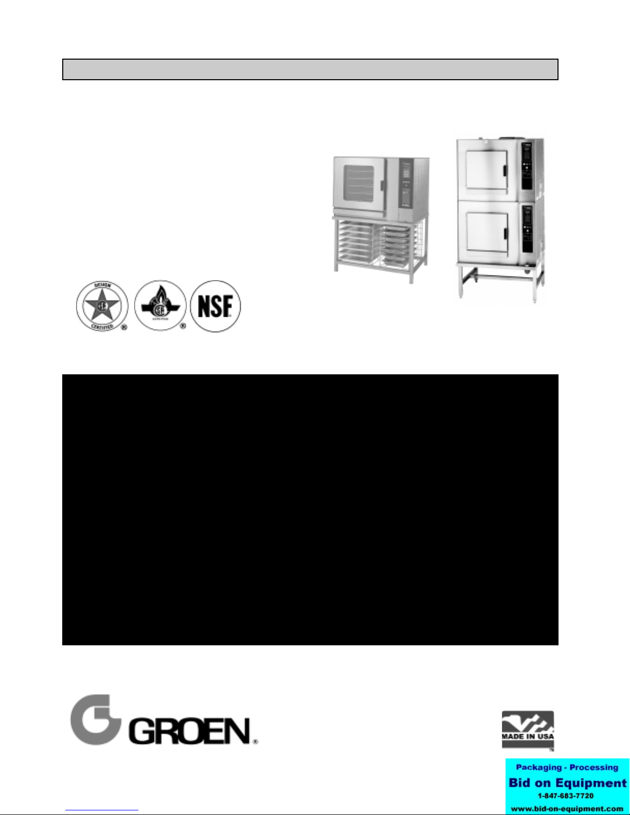
MODEL: CC10-G, (2)CC10-G
C/2-20G, (2)C/2-20G
CONVECTION COMBO™
Combination Steamer-Oven
C/2-20GF with
optional pan racks
THIS MANUAL MUST BE RETAINED FOR FUTURE REFERENCE. READ, UNDERSTAND AND
FOLLOW THE INSTRUCTIONS AND WARNINGS CONTAINED IN THIS MANUAL.
(2)CC10-GF
FOR YOUR SAFETY
DO NOT STORE OR USE GASOLINE OR OTHER FLAMMABLE VAPORS
AND LIQUIDS IN THE VICINITY OF THIS OR ANY OTHER APPLIANCE .
POST IN A PROMINENT LOCATION
INSTRUCTIONS TO BE FOLLOWED IN THE EVENT USER SMELLS GAS.
THIS INFORMATION SHALL BE OBTAINED BY CONSULTING YOUR LOCAL
GAS SUPPLIER. AS A MINIMUM, TURN OFF THE GAS AND CALL YOUR
GAS COMPANY AND YOUR AUTHORIZED SERVICE AGENT. EVACUATE
ALL PERSONNEL FROM THE AREA.
WARNING: IMPROPER INSTALLATION, ADJUSTMENT, ALTERATION,
SERVICE OR MAINTENANCE CAN CAUSE PROPERTY DAMAGE, INJURY
OR DEATH. READ THE INSTALLATION, OPERATING AND MAINTENANCE
INSTRUCTIONS THOROUGHLY BEFORE INSTALLING OR SERVICING THIS
EQUIPMENT.
Information contained in this document is
known to be current and accurate at the time
of printing/creation. Unified Brands recommends referencing our product line websites,
unifiedbrands.net, for the most updated
product information and specifications.
Page 2

OM-CC-G and C/2-G
IMPORTANT — READ FIRST — IMPORTANT
WARNING: THE UNIT MUST BE INSTALLED BY PERSONNEL QUALIFIED TO WORK WITH GAS,
ELECTRICITY AND PLUMBING. IMPROPER INSTALLATION CAN CAUSE INJURY TO
PERSONNEL AND/OR DAMAGE TO THE EQUIPMENT. THE UNIT MUST BE INSTALLED IN
ACCORDANCE WITH APPLICABLE CODES.
CAUTION: SHIPPING STRAPS ARE UNDER TENSION AND CAN SNAP BACK WHEN CUT.
CAUTION: DO NOT INSTALL THE UNIT IN ANY WAY WHICH WILL BLOCK THE RIGHT SIDE VENTS,
OR WITHIN 12 INCHES OF A HEAT SOURCE SUCH AS A BRAISING PAN, FRYER, CHAR
BROILER OR KETTLE.
CAUTION: LEVEL THE UNIT FRONT TO BACK, OR PITCH IT SLIGHTLY TO THE REAR, TO AVOID
DRAINAGE PROBLEMS.
WARNING: TO AVOID DAMAGE OR INJURY, FOLLOW THE WIRING DIAGRAM EXACTLY WHEN
CONNECTING A UNIT.
CAUTION: DO NOT USE PLASTIC PIPE. DRAIN MUST BE RATED FOR BOILING WATER.
WARNING: DO NOT CONNECT THE DRAIN DIRECTLY TO A BUILDING DRAIN.
WARNING: BLOCKING THE DRAIN IS HAZARDOUS.
IMPORTANT: Improper drain connection will void warranty.
IMPORTANT: Do not allow any water traps in the line. A trap can cause pressure to build up inside the
cavity during steaming, which will make the door gasket leak.
WARNING: WHEN YOU OPEN THE DOOR, STAY AWAY FROM STEAM COMING OUT OF THE UNIT.
STEAM CAN CAUSE BURNS.
WARNING: BEFORE CLEANING THE OUTSIDE OF THE OVEN, DISCONNECT THE ELECTRIC POWER
SUPPLY. KEEP WATER AND CLEANING SOLUTIONS OUT OF CONTROLS AND
ELECTRICAL COMPONENTS. NEVER HOSE OR STEAM CLEAN ANY PART OF THE UNIT.
WARNING: ALLOW COOKING CHAMBER TO COOL BEFORE CLEANING.
WARNING: CAREFULLY READ THE WARNINGS AND FOLLOW THE DIRECTIONS ON THE LABEL OF
EACH CLEANING AGENT.
RECOMMENDED BY DELIMING AGENT MANUFACTURER.
WARNING: DO NOT MIX DE-LIMING AGENTS (ACID) AND DE-GREASERS (ALKALI).
WARNING: DO NOT PUT HANDS OR TOOLS INTO THE COOKING CHAMBER UNTIL THE FAN HAS
STOPPED TURNING.
WARNING: DO NOT OPERATE THE UNIT UNLESS THE REMOVABLE RIGHT SIDE PANEL HAS BEEN
RETURNED TO ITS PROPER LOCATION.
NOTICE: DO NOT USE A CLEANING OR DE-LIMING AGENT THAT CONTAINS ANY SULFAMIC ACID
OR ANY CHLORIDE, INCLUDING HYDROCHLORIC ACID. IF THE CHLORIDE CONTENT OF
ANY PRODUCT IS UNCLEAR, CONSULT THE DISTRIBUTOR OR MANUFACTURER.
NOTICE: DO NOT USE ANY DE-GREASER THAT CONTAINS POTASSIUM HYDROXIDE OR SODIUM
HYDROXIDE OR THAT IS ALKALINE.
WARNING: USE OF ANY REPLACEMENT PARTS OTHER THAN THOSE SUPPLIED BY GROEN OR
THEIR AUTHORIZED DISTRIBUTOR VOIDS ALL WARRANTIES AND CAN RESULT IN
BODILY INJURY TO THE OPERATOR AND DAMAGE THE EQUIPMENT. SERVICE BY
OTHER THAN FACTORY-AUTHORIZED PERSONNEL WILL VOID ALL WARRANTIES.
WARNING: HIGH VOLTAGE EXISTS INSIDE CONTROL COMPARTMENTS. DISCONNECT FROM
BRANCH BEFORE SERVICING. FAILURE TO DO SO CAN RESULT IN SERIOUS INJURY
OR DEATH.
USE SAFETY GLASSES AND RUBBER GLOVES AS
2
Page 3

OM-CC-G and C/2-G
Table of Contents
IMPORTANT OPERATOR SAFETY WARNINGS .................................. 2
EQUIPMENT DESCRIPTION ................................................. 4
INSPECTION AND UNPACKING .............................................. 5
WATER QUALITY AND TREATMENT .......................................... 6
INSTALLATION ............................................................7
INITIAL START-UP ........................................................ 11
OPERATING INSTRUCTIONS ............................................... 13
CLEANING ............................................................... 19
MAINTENANCE .......................................................... 23
TROUBLESHOOTING ...................................................... 23
DIAGRAMS AND SCHEMATICS .............................................. 25
REFERENCES............................................................ 26
SERVICE LOG ............................................................ 27
3
Page 4
OM-CC-G and C/2-G
Equipment Description
Your Groen Convection Combo™ has a stainless
steel cooking chamber, an air heating compartment
with heat exchange tubes and fan, a steam
generator, and a control compartment which houses
electrical components.
All major components of the Convection Combo™
are encased in a 16 gauge stainless steel cabinet.
The cabinet is lined with 1½ to 2 inches (4 to 5 cm)
thick glass fiber insulation. A removable drip tray is
located beneath the door.
The door is reversible so that it may open from the
left or right. Operator controls are located on the right
front of the unit, except for the pilot control switch
and manual gas shut-off valve, which are behind the
sliding access door on the right side of the unit.
Standard controls let you to operate the Convection
Combo in any one of three cooking modes:
1. As a convection oven
2. As a self-contained pressureless steamer
3. As a combination oven-steamer
Models CC10-G and C/2-20G differ in cooking
chamber size and pan capacity:
CC10-G: 4 steam table pans (12x20x2½”), or
7 half-size (13x18") US bake pans
C/2-20G: 10 steam table pans (12x20x2½”), or
9 full-size (18x26") US bake pans
Units are supplied on a stainless steel stand. The
smaller Convection Combo™ is available as the
single CC10-GF or the double stacked (2) CC10-GF.
The larger unit is available as the single C/2-20GF or
the double-stacked (2)C/2-20GF.
Controls and monitoring displays for cooking times,
operating mode and temperature selection are on
the control panel. The upper portion of the panel has
a digital cooking time readout and touch pads for
setting cook times. Below the timer section are lights
which indicate the status of the unit and touch pads
to select the mode of operation and to switch on
power.
this port into a fill tank, from which it is transferred to
the steam generator during the unique Groen
automatic cleaning cycle.
The air heating space which contains the heat
exchanger tubes is also separated from the cooking
chamber by removable left, right, top and bottom
partitions. The compartment which contains the
unit’s automatic controls and other electrical
components is on the right side of the unit, and is
accessed by removing the right outside panel.
A drain is located in the removable bottom of the
cooking chamber. Fluids drain from this removable
bottom and from the permanent floor to the stainless
steel drain pipe outside the oven. The drain pipe
includes a spray condensor which suppresses any
steam escaping from the chamber and a drain box.
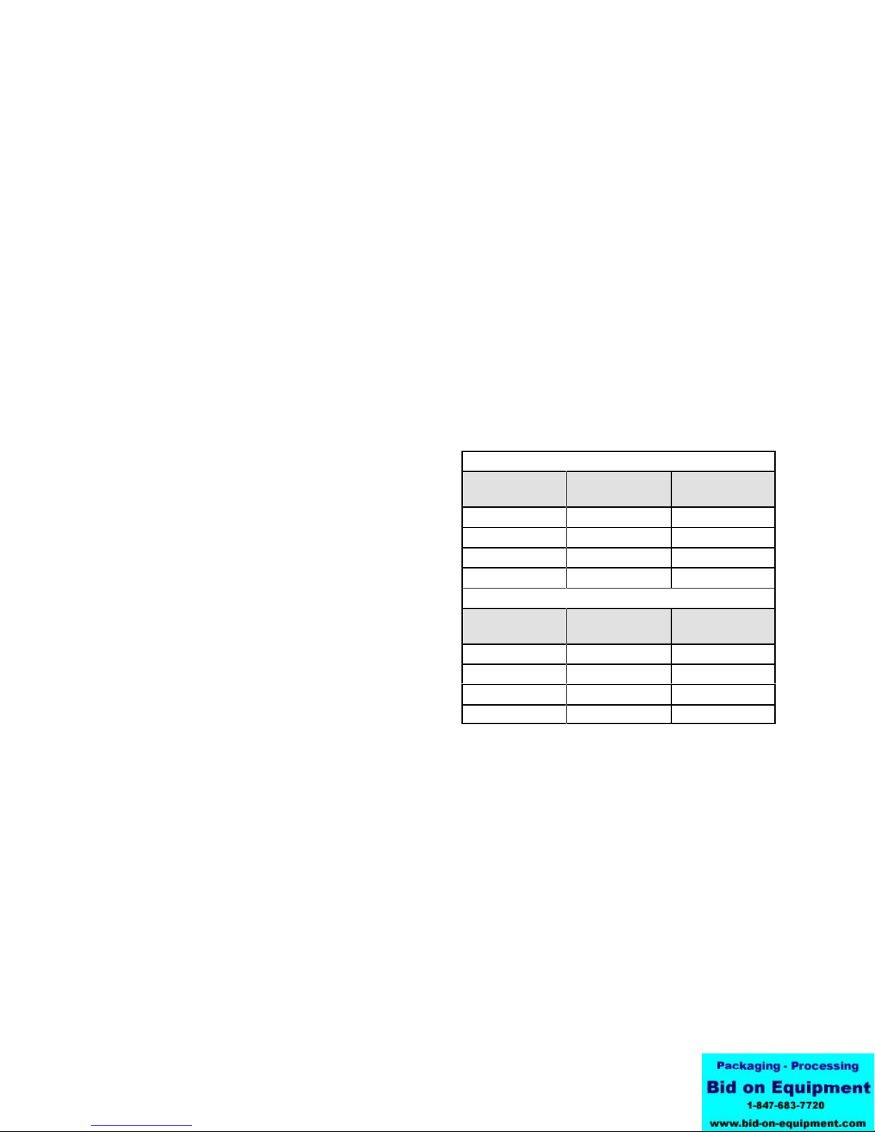
BURNER FIRING RATES
Input Rates, BTU/hour
CC10-G or per chamber for (2)CC10-G
Mode
Oven 45,000 45,000
Steam 48,000 48,000
Combo 54,600 54,600
Preheat (Max) 93,000 93,000
C/2-20G or per chamber for (2)C/2-20G
Mode
Oven 90,000 90,000
Steam 100,000 100,000
Combo 100,000 100,000
Preheat (Max) 186,000 186,000
*Manifold Pressure
Natural Gas
at 3.7" W.C.*
Natural Gas
at 4.5" W.C.*
L.P. Gas
at 10.5" W.C.*
L.P. Gas
at 10.0" W.C.*
A digital readout shows the selected temperature,
which is entered by turning a dial. Pilot burner
status is shown by a light on the pilot ignition switch.
An insulated, gas-fired steam generator is mounted
behind the oven. Steam enters the oven through a
connecting tube near the bottom left rear corner of
the oven.
The deliming port is located on the stand just below
the control panel. De-liming solution goes through
4
Page 5
Inspection and Unpacking
OM-CC-G and C/2-G
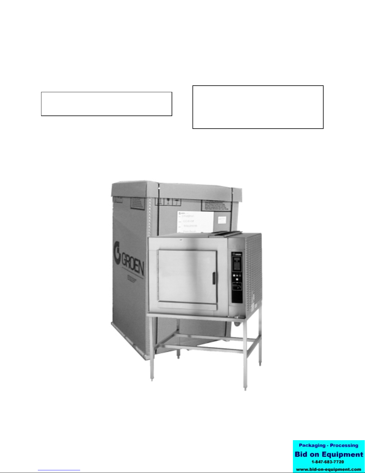
Your Convection Combo™ will be completely
assembled in a heavy shipping carton (CC10-G) or
wooden crate (C/2-20G), and attached to a skid. On
receipt, inspect the carton or crate carefully for
exterior damage.
CAUTION
SHIPPING STRAPS ARE UNDER TENSION AND
CAN SNAP BACK WHEN CUT.
Carefully cut the straps around the carton and detach
the sides of the carton from the skid. Pull the carton
up off the unit. Be careful to avoid personal injury or
equipment damage from nails and sharp pieces of
wood or staples which might be left in carton walls.
Write down the model number, serial number and
installation date and keep this information for future
reference. Space for these entries is provided at the
top of the Service Log in the back of this manual.
CAUTION
THIS UNIT IS VERY HEAVY. YOU SHOULD GET
HELP AS NEEDED AND USE MATERIAL
HANDLING EQUIPMENT TO REMOVE THE UNIT
FROM THE SKID AND MOVE IT TO ITS PLACE
OF INSTALLATION.
When starting installation, use material handling
equipment to lift the unit straight up off the skid.
Check packing materials to make sure loose parts
are not discarded with the material.
The unit will be delivered in either a heavy carton (CC10-G
and C/2-20GF) or a heavy wooden crate ((2)CC10-G and
(2) C/2-20GF), strapped to a wooden skid. (CC10-GF
pictured)
5
Page 6
OM-CC-G and C/2-G
Water Quality and Treatment
It is essential to supply the steam generator/boiler
with water that will not form scale. Even though the
steam generator/boiler is engineered to minimize
scale formation, scale development depends on the
hardness of your water and the number of hours you
operate the equipment each day.
Most water supplies contain minerals which form
scale. It is this scale which could lead to an early
component failure.
Your local water utility can tell you about the
minerals in your water. The water going to the
steam generator should have between 30 and 40
parts per million (ppm) total dissolved solids (TDS)
and should have a pH (acidity rating) of 7.0 to 9.0.
Please follow these simple precautions:
1. The best way to prevent scale is to use a Groen
Water Treatment System which has been
specifically designed for Groen steamers and
combination ovens. Do not rely on unproven
water treatments sold for scale prevention and
removal. They are not specifically designed
to work with Groen steamers and
combination ovens.
2. A well-maintained water treatment system and a
regular cartridge replacement schedule is
essential.
3. Using a Groen water treatment system will
provide longer steam generator/boiler life, higher
steam capacity, and reduce maintenance
requirements.
4. If you notice a slowdown in steam production or
an increase in deliming, have the Combo
checked for scale build-up. This could be an
indication that the water treatment cartridges
need replacing. Heavy scale reduces the unit’s
ability to boil water, and can even cause
component failure.
MINIMIZE SCALE PROBLEMS BY INSTALLING
AND MAINTAINING A GROEN WATER
TREATMENT SYSTEM AND BY DELIMING THE
STEAM GENERATOR/BOILER REGULARLY.
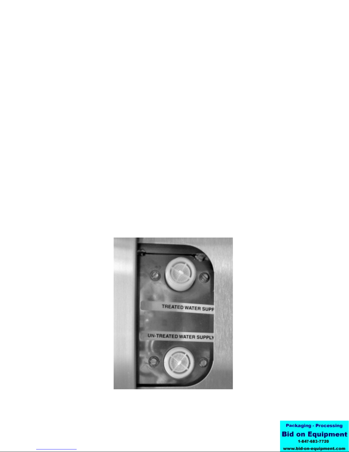
Groen Convection Combo™ ovens feature two
separate water inlets — one for the steam
generator/boiler (for treated water), the other for the
spray condenser (untreated water). The second
intake will reduce water treatment requirements
resulting in significant savings.
The dual water connections are on the rear of the
unit.
Standard water connections for steam
generator and drain spray condenser.
6
Page 7

OM-CC-G and C/2-G
Installation and Start-Up
WARNING
THE UNIT MUST BE INSTALLED BY PERSONNEL WHO ARE QUALIFIED TO WORK WITH GAS,
ELECTRICITY AND PLUMBING. IMPROPER INSTALLATION CAN CAUSE INJURY TO PERSONNEL AND/OR
DAMAGE TO THE EQUIPMENT. THE UNIT MUST BE INSTALLED IN ACCORDANCE WITH APPLICABLE
CODES.
CAUTION
DO NOT INSTALL THE UNIT WITH THE RIGHT SIDE VENTS BLOCKED OR WITHIN 12 INCHES OF A HEAT
SOURCE (SUCH AS A BRAISING PAN, DEEP FRYER, CHAR BROILER OR KETTLE).
DO NOT INSTALL TO THE LEFT OF ANY OPEN-FLAME EQUIPMENT. DO NOT INSTALL UNIT WITHIN FOUR
FEET OF A STEAM DRAIN.
TO AVOID DRAINAGE PROBLEMS, LEVEL THE UNIT FRONT TO BACK.
INSTALLATION MUST BE IN ACCORDANCE WITH ALL APPLICABLE CODES.
Installation
1. Mounting
2. Gas Supply Connections
Minimum rear clearance is 6" from back of oven.
If you wish to install a Convection Combo™ on
top of another, you should obtain a double
stacked unit from the factory.
The unit must be installed in an adequately
vented room with a provision for an ample air
supply to the unit. The unit must be installed
completely under a ventilation hood, since flue
products exit the appliance over its entire depth.
Anything which might restrict the flow of air for
ventilation and combustion must be removed.
Do not obstruct the flue cover or any front, side,
top or rear vents after installation. The area
directly around the Convection Combo™ must
be cleared of all combustible material.
Installation must comply with local codes, or in
the absence of local codes, conform to the
National Fuel Gas Code ANSI Z223.1 - latest
edition, including:
“The appliance and its individual shut-off valve
must be disconnected from the gas supply
piping system during any pressure testing of that
system at test pressures in excess of ½ psig
(3.45 kPa). The appliance must be isolated
from the gas supply by closing its individual
manual shut-off valve during any pressure
testing of the gas supply piping system at test
pressures equal to or less than ½ PSI (3.45
kPa).”
THIS UNIT IS FOR COMMERCIAL USE. NEVER
WARNING
USE HOME OR RESIDENTIAL GRADE GAS
CONNECTIONS. THEY DO NOT MEET GAS
CODES AND COULD BE HAZARDOUS.
Connect to the gas supply using ½ NPT pipe for
the CC10-E and ¾ NPT pipe for the C/2-20E or
an approved equivalent. Although the immediate
connection to the Convection Combo™ is either
½ or ¾ NPT, the gas supply piping must be large
enough to provide 93,000 BTU/hour for each
CC10-G cooking chamber or 186,000 BTU/hour
for each C/2-20G cooking chamber. Supply
pressure must be at least 5" W.C. (maximum 14"
W.C.) for natural gas or 12" W.C. (maximum 14"
W.C.) for LP gas. In Canada, the installation
must conform to the Canadian Gas Code, CAN
1-B149, Installation Codes for Gas Burning
Appliances and Equipment, and/or local codes.
For units on casters, complete the gas supply
connection using only connectors that meet the
standards for movable gas appliances, ANSI
Z21.69 — latest edition. Restrain movement of
the unit by attaching a cable or chain to the
eyelet (provided at the back of the frame) and
anchoring the cable or chain to the wall or floor.
Make the length and location of the cable such
that the unit cannot pull on the gas connection
while the cable is connected.
7
Page 8
OM-CC-G and C/2-G
2. Electrical Supply Connection
For a single oven, or for each oven in a double
stacked unit, provide 115 VAC, 60 Hz, single
phase, 15 AMP service. Local codes and/or the
National Electrical Code should be observed in
accordance with ANSI/NFPA 70-1987 (or latest
edition). AN ELECTRICAL GROUND IS
REQUIRED. The electrical schematic is located
in the service compartment and this manual.
Maximum load per oven is 5½ AMPs. In
Canada provide electrical service in accordance
with the Canadian Electrical Code, CSA C22.1
Part 1, and/or local codes.
4. Water Supply Connection
A check valve (anti-siphonage device) must be
installed in the incoming cold water lines in
keeping with local plumbing codes. Water line
pressure should be between 30 and 60 PSI (210
and 410 kPa). A pressure regulator is required
above 60 PSI (410 kPa).
A ¾ inch (19 mm) NH connector is required to
connect each water supply to the water inlet
valve. The water feed line diameter may not be
less that ½ inch (13 mm). Use a washer (or if
necessary, two washers) in the hose connection.
Do not allow the connections to have any leaks,
no matter how small.
Minimum flow rate for water delivery is 1.5
gallons per minute. Below this rate your Combo
oven will not operate. Condensate spray rate at
30 PSI is 0.34 gallons per minute for CC10-G
units, and 0.7 gallons per minute for the
C/2-20G. Double stacked units require double
the rates. To convert a steamer or combination
oven to a single water connection, order single
cold water adapter (part # 138473).
5. Drain Connection
a. Unit Without Drain Tank
(See figures on page 10)
A 1½ inch (4 cm) ID (CC10-G) or 2 inch (5
cm) ID hose (C/2-20G) may be attached to
the supplied drain outlet with a clamp. Do
not use plastic pipe, because the drain must
withstand very hot water.
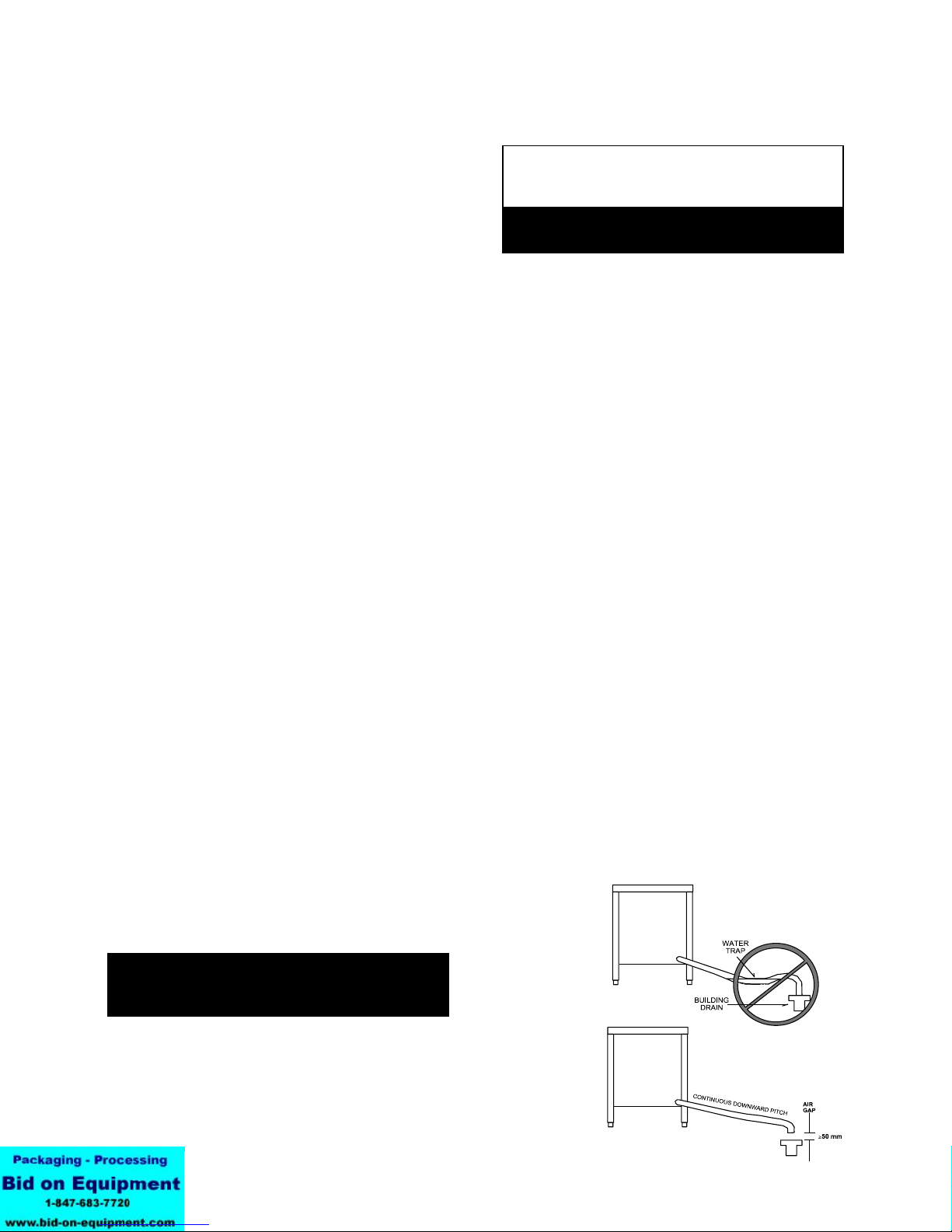
other elbows or other restrictions between
the unit drain and the free air gap.
CAUTION
DO NOT USE PLASTIC PIPE. DRAIN MUST BE
RATED FOR VERY HOT WATER.
WARNING
BLOCKING THE DRAIN IS HAZARDOUS.
On a double stacked unit, there must be a
minimum of two inches free air gap on each
drain, as close to each oven as possible.
Double stacked units may only share a
common drain hose downstream of both
free air gaps.
Install the drain line with a constant
downward pitch. This is especially important
for double-stack units. The bottom unit is
conceptually shown below.
IMPORTANT: Do not allow any water traps in the
line. A trap can cause pressure to build up
inside the cavity during steaming, which will
make the door gasket leak.
NOTE: Improper drain connection will void the
warranty.
b. Units With Drain Tank
(See figures on page 10)
A hose may be attached to the supplied
drain elbow with a clamp. Use 1½ inch ID
hose for CC10-G or 2" ID hose for C/2-20G.
The hose may be connected directly to a
building drain since the drain tank has an air
vent, which eliminates the need for a free air
gap at the building drain.
Do not block the air vent in any way. Do not
attach anything to the vent tube or reduce its
size.
Do NOT use plastic pipe in the drain line,
because the drain must withstand very hot
water.
WARNING:
DO NOT CONNECT THE OVEN DRAIN
DIRECTLY TO A BUILDING DRAIN.
There must be a free air gap between the
end of the hose and the building drain. The
free air gap should be as close as possible
to the unit’s drain. There must also be no
8
Page 9

OM-CC-G and C/2-G
Convection Combo™ Utility Connections
NOTE: Remove right side panel to make connections
at terminal block in rear of control compartment.
9
Page 10

OM-CC-G and C/2-G
Proper Drain Line Connections
10
Page 11

Initial Start-Up
OM-CC-G and C/2-G
ANY POTENTIAL USER OF THE EQUIPMENT SHOULD BE TRAINED IN SAFE AND CORRECT OPERATING
PROCEDURES.
After the Convection Combo™ has been installed,
test it to ensure that it is operating correctly.
1. Remove all literature and packing materials from
the interior and exterior of the unit.
2. Check that the cold water supply line is open and
that the fittings are not leaking.
3. Make sure that the gas supply line is open. On
newer units, turn the knob of the main gas valve
so that it is lined up with the pipe.
WARNING
7. Once the pilot burner flame has been
established (the green light at the pilot switch is
on), all operator commands are executed via the
front control panel touch pads. See the
Operation section for details.
8. High Altitude Operation. At altitudes above
5,000 feet (1524m), the unit will not operate in
the Steamer or Combo Modes unless the altitude
is set. The Convection Combo™ is delivered
with the altitude set for 1000 feet as default. You
can program the altitude as follows:
a. If the unit is on, turn it off by pressing the ON
touch pad.
b. Press and hold the STEAM touch pad while
turning the unit on by pressing the ON touch
pad. The Time/Status display will show the
letters AL and a number representing the
altitude in thousands of feet. If the altitude
has not been set for your unit, the display
will be 0.
These controls are behind the sliding door on
the right side panel, facing the unit.
4. Turn on electrical service to the unit. Because
the unit will not operate without electrical
power, no attempt should be made to operate
the unit in the event of a power failure.
5. The control panel will not operate until the pilot
burner has been ignited. To light the pilot
burner, activate the pilot switch located next to
the main gas valve. Once the pilot ignition
sequence has been successfully completed, a
green light will glow, and power will be supplied
to the front panel.
6. The “trial for ignition” period is roughly 90
seconds. If the pilot burner does not light within
90 seconds of pilot switch activation, the ignition
system automatically stops the gas flow to the
pilot burner and cancels the ignition trial. If the
ignition trial is terminated, turn off the pilot switch
and repeat the trial for ignition. During initial
start-up, the pilot may require several trials in
order to bleed air from the gas piping.
Subsequent start-up should only require about
five seconds to achieve ignition.
NOTE: See Automatic Operation of Pilot at the end
of this section.
c. Enter an altitude value between 0 and 15,
using the numbered touch pads. For
example, if the unit will be operating at 7,000
feet, enter 7.
d. Press the START touch pad to accept the
change.
Altitude Metric Conversion
Altitude
Feet Meters
1000 305 1
2000 610 2
3000 914 3
4000 1219 4
5000 1524 5
6000 1830 6
7000 2133 7
8000 2438 8
9000 2745 9
10000 3048 10
11000 3353 11
12000 3658 12
13000 3962 13
14000 4267 14
15000 4572 15
Setting
11
Page 12

OM-CC-G and C/2-G
9. Select Fahrenheit or Celsius Temperatures.
The Convection Combo™ is delivered with the
Fahrenheit scale as default. To change the
temperature scale, hold the 5 key in, and press
ON. The Time/Status display will show dEG°F or
dEG°C. Press the 5 key to change from one to
the other. Press START to accept the change.
10. To Test Steamer Mode Operation, turn on the
unit. (For operating procedure details, see the
Operation section of this manual.) Clear time
from the time display. Close the door and press
the STEAM touch pad. (If the HOT light is on,
see Fast Cool in the Operation section.)
The WAIT light will stay on while the steam
generator fills with and heats the water. It should
turn off within three minutes, and the READY
light should come on. This indicates that the
water is at its standby temperature. The timer
only controls operations in the Steamer Mode.
Enter a time and press START. (“Time” is set in
minutes and hours only. Seconds are not
displayed).
Examples: 2 minutes = 00:02
(Just press 2).
1 hour and 30 minutes = 01:30
(Press 1, 3, and 0, or press 9 and 0
the timer will change to 1:30)
The colon [:] between the numbers will blink and
the generator will begin to produce steam. Time
only counts down when the READY light is lit.
11. Test Combo Mode Operation, turn on the
power and clear any time from the Time/Status
display. Press the COMBO touch pad. Set the
COOK temperature to 350
o
F (175oC). The WAIT
light will come on. It will remain on while (1) the
steam generator fills with water and heats it to its
standby temperature and (2) the air heater raises
the air temperature to 350
o
F. Both actions
should be completed in five to eight minutes,
starting with a cold unit. When the set
temperature is attained, the WAIT light will go
off, and the READY light will come on. NOTE:
The timer does not control the oven in either the
Combo or Oven Modes.
12. Test Oven Mode Operation, turn on the power
and clear the Time/Status display. Press the
OVEN touch pad. Set the cook temperature to
o
350
F (175oC). The WAIT light will come on.
Within eight minutes of a cold start, the WAIT
light should go out and the READY light come
on. When that happens, turn the COOK setting
down to 320
o
F (160oC). The HOT light will come
on. Heat-up times may vary slightly with voltage
or water pressure differences.
13. To shut down the unit, switch off the power. The
pilot burner may also be turned off to conserve
energy.
14. If the Convection Combo™ works as described,
the unit is functioning correctly and is ready for
use.
NOTE: You cannot change modes if the timer is
running.
WARNING
WHEN YOU OPEN THE DOOR, STAY AWAY
FROM STEAM COMING OUT OF THE UNIT.
THE STEAM CAN CAUSE BURNS.
12
Page 13

OM-CC-G and C/2-G
Operation
WARNING
ANY POTENTIAL USER OF THE EQUIPMENT SHOULD BE TRAINED IN SAFE AND CORRECT OPERATING
PROCEDURES.
DO NOT OPERATE THE UNIT AT ALL, UNLESS ALL FOUR REMOVABLE COOKING COMPARTMENT
PARTITIONS HAVE BEEN RETURNED TO THEIR PROPER LOCATION.
DO NOT OPERATE THIS EQUIPMENT WITHOUT ELECTRIC POWER.
NOTE: Before the control panel can be used, the pilot burner flame must be on. See “Initial Start-Up.”
A. Controls and Indicators
Operator controls are on the right front side of the
unit. Their use is described below:
1. Time Section
In Oven and Combo Modes, the timer functions
only as a “cooking time minute minder” and does
not turn the unit on or off. In the Steamer Mode,
however, it controls the steaming function.
a. Time/Status Display — Shows operating
time remaining in the Steamer, Oven or
Combo Mode. The timer counts down. If
the unit is equipped with, and operating in
the optional Hold Mode, the timer will count
up alternating with the word “Hold,” and will
show the total accumulated time that the
product has been holding. The display
shows operating time in “hours:minutes”
format. For example, entering 9 and 0 will
result in a display of 01:30.
b. Number touch pads — used to enter time
values.
c. CLEAR — Pressing this touch pad once
stops the beeper and resets the timer to the
time that was last set. Pressing twice clears
it to 00:00. At the end of a cooking period,
opening the door is the same as pressing
CLEAR once.
d. START — Press this touch pad to start the
timer. If the unit is in Steamer Mode, it will
also cause steaming to begin.
2. Status Lights
a. HOT — Indicates chamber temperature is
more than 15
temperature. (See Paragraph 5 in this
section)
o
F (8oC) over the set
b. SERVICE — Indicates that there is a
problem which might require a service call.
If there is such a problem, the beeper will
sound and the SERVICE light will be on
when you switch on the power. The unit
may continue to operate, depending on the
type of problem. Refer to the
Troubleshooting section to determine the
nature and severity of the problem.
c. WAIT — Indicates the unit is either heating
or cooling toward the set temperature. The
HOT and WAIT lights will both be on if the
chamber is more than 15
set point.
d. READY — Indicates the unit is ready for
use.
e. CLEAN - Indicates the unit needs cleaning.
The unit will temporarily function if this light
is flashing.
3. Cooking Mode Selection
These touch pads are used to select the mode of
operation. If a mode is off, pressing the pad for
that mode will turn it on. If the mode is on,
pressing its pad will turn it off. A light just above
each pad indicates which has been selected.
o
F (8oC) above the
13
Page 14

OM-CC-G and C/2-G
Standard Operating Controls
14
Page 15

OM-CC-G and C/2-G
a. STEAM — Selects steamer operation only.
b. COMBO — Selects superheated steam and
convection oven operation.
c. OVEN — Selects convection oven operation
only.
4. Power
The ON touch pad turns the unit on or off. When
power is on, the ON light just above the touch
pad is lit. Use of this pad does not reset the
controls. The unit will always come on in the
same mode it was in when shut down.
5. Temperature (TEMP) Section
a. The Cook display shows the selected
temperature in either Oven or Combo Mode.
It is blank in the Steamer Mode.
b. Turning the Temperature Control Knob
selects the cooking temperatures in 5
increments. The control ranges are:
Oven Mode 200-575
Combo Mode 220-575
o
F (95-300oC)
o
F (105-300oC)
B. Operating Instructions
1. Steam Mode
a. If the unit is off, switch on the electric power
by pressing the ON touch pad. (If the
SERVICE light comes on when you turn on
the power, see the Troubleshooting section).
b. If the power is already on, and there is a
number in the time display window, press
the CLEAR touch pad one or more times to
reset the time to zero.
NOTE: You cannot change operating modes
while the timer is running
c. The unit will be in the mode of operation in
which it was last used. Because of this, the
indicator light for that mode will be lit. If the
unit is not already in the Steamer Mode,
press the STEAM touch pad. The STEAM
light will come on and the Cook display will
go blank.
d. If the unit was recently used in Oven or
Combo Mode, the HOT light may come on,
indicating that the cooking chamber is too
hot for use as a steamer. The unit can be
cooled quickly to the steaming temperature
range by leaving the door open or following
the Fast Cool procedure described near the
end of this section (Paragraph 4). With the
door open, the generator can fill and heat
o
F
the water to 200
produce steam.
o
F (93oC), but it cannot
NOTE: Maximum temperature is limited to
500°F when either the optional probe or
optional hold mode is in use.
6. Optional Features
If the following features are included, please
refer to the control panel guide which was
provided with the unit:
Cook Only Guide: P/N 121084
Programmable: P/N 121042
Probe & Hold: P/N 121072
WARNING
WHEN YOU OPEN THE DOOR STAY AWAY
FROM ANY STEAM COMING OUT OF THE UNIT.
STEAM CAN CAUSE BURNS.
e. The WAIT light will be on until the water
reaches 200
o
F (93oC). It will then turn off
and the READY light will come on. You are
now ready to steam foods in your
Convection Combo™.
f. Load the food into pans in an even, uniform
layer.
g. Carefully open the door and slide the pan or
pans onto the pan racks in the cooking
chamber. If you are only using one pan,
place it in the middle position. Close the
door.
15
Page 16

OM-CC-G and C/2-G
h. Press the numbered touch pads to set the
cooking time. The time will appear in the
Time/Status display. If you enter the wrong
number, press the CLEAR touch pad to
erase the time from the display, and enter
the time again.
i. When the correct cooking time has been
entered, press the START pad. The colon in
the Time/Status display will blink and the
time will count down the cooking time. (The
unit must be READY before the timer can
count down.)
j. If you open the door during the cooking
period, steaming and the timer will stop (but
will not reset). When you close the door,
steaming and timing will resume.
WARNING
WHEN YOU OPEN THE DOOR STAY AWAY
FROM ANY STEAM COMING OUT OF THE UNIT.
STEAM CAN CAUSE BURNS.
k. When the timer reaches zero, it stops steam
generation and sounds a beeper. Water in
the steam generator stays at its standby
temperature (200
o
F - 93oC). On older
models, the beeper will sound until the door
is opened or CLEAR is pressed.
l. Carefully open the door. If the food is
cooked, remove the pans using hot pads or
oven mitts to protect your hands.
m. After the display has counted down to zero,
opening the door or pressing CLEAR once
will reset the display to the time that was last
used. Pressing START will repeat the cook
cycle. If the same cooking time will be used,
you only need to press the number keys
when you first set that time.
n. After the Time/Status display has counted
down to zero, you can reset the time to zero
by either (1) opening the door and pressing
CLEAR or pressing CLEAR twice. A new
cooking time may then be set by using the
number keys.
2. Oven Mode
If the door is closed and the cooking
temperature is above 250
o
F (120oC) the fan
will begin to operate.
b. If the power is already on, and there is a
number in the Time/Status display, press
CLEAR one or more times to reset the time
to zero.
NOTE: You cannot change operating modes
while the timer is running
c. The unit will power up in the mode in which it
was last used. Because of this, the indicator
light for that mode will be lit. If the unit is not
already in the Oven Mode, press the OVEN
touch pad. The OVEN light will come on and
the oven fan will operate.
d. Use the Temperature Control Knob to set
the desired cooking temperature between
o
200
and 575o F (93o to 300o C). NOTE:
Maximum temperature is limited to 500°F
when the either the optional probe or
optional hold mode is in use. The
temperature will appear in the Cook display.
Unless the cooking chamber is already at or
above the selected temperature, the unit will
start heating and the WAIT light will come
on.
e. If the unit was recently used at a
temperature 15
o
F (8oC) or more over the
selected temperature, the HOT and WAIT
lights will come on. The unit can be cooled
quickly to the desired cooking temperature
by leaving the door open or following the
Fast Cool procedure described near the end
of this section (Paragraph 4).
f. The READY light will indicate when the oven
is at the desired temperature.
g. Load the food into the pan or pans in a
uniform layer.
h. The Convection Combo™ will operate in
Oven Mode with the timer either on or off. If
you want to time cooking, press the
numbered pads in the Time/Status portion of
the control panel to set the cooking time.
The time will appear in the Time/Status
display . If you enter the wrong number,
press CLEAR to erase the time from the
display, and reenter the time. Remember
that the timer does not control the unit in
the Oven Mode.
a. To use the Convection Combo™ as a
convection oven, switch on the electric
power by pushing the ON touch pad. (If the
SERVICE light comes on when you turn on
the power, see the Troubleshooting section).
16
Page 17

i. Open the door and slide the pan or pans
onto the pan racks in the cooking chamber.
If you are only using one pan, place it in the
middle position. Close the door.
j. If the correct time has been set on the timer,
press the START pad. The colon [:]
between the numbers in the Time/Status
display will blink and the time will count
down the cooking time. When the timer has
counted down to zero, it will sound a beeper.
This sound will continue until the door is
opened or the CLEAR pad is pressed.
k. To stop cooking, take the pans out of the
oven using hot pads or oven mitts to protect
your hands from the hot pans. The unit will
continue heating to keep the chamber at the
set temperature until the temperature control
is reset, or the power is shut off.
OM-CC-G and C/2-G
NOTE: You cannot change operating modes
while the timer is running
c. The unit will power up in the mode of
operation in which it was last used. Because
of this, the indicator light for that mode will
be lit. If the unit is not already in the Combo
Mode, press the COMBO touch pad. The
COMBO light will come on and if the steam
generator is not already full, water will flow
into it and begin heating.
d. Use the Temperature Control Knob to set
the desired oven temperature between 220
and 575
will appear in the Cook display.
e. If the unit was recently used at a
temperature more than 15
than the temperature selected, the HOT and
WAIT lights will turn on. The unit can be
cooled quickly by leaving the door open or
following the Fast Cool procedure described
near the end of this section (Paragraph 4).
o
F (105 to 300oC). The temperature
o
F (-8oC) higher
WARNING
PANS AND INTERNAL PARTS OF THE OVEN
WILL BE VERY HOT. AVOID CONTACT WITH
HOT SURFACES.
l. Opening the door during operation shuts off
power to the heaters and fan and stops the
timer, but it has no other effect on the
controls. When the door is closed, operation
continues. Note that cooking time will be
extended by the period the door was open.
3. Combo Mode
a. If the unit is off, switch on the electric power
by pressing the ON touch pad. (If the
SERVICE light comes on when you turn on
the power, see the Troubleshooting section).
If the door is closed and the cooking
temperature is above 200
o
F (93oC) the fan
will begin to operate.
b. If the power is already on, and there is a
number in the time display window, press
the CLEAR touch pad one or more times to
reset the time to zero.
WARNING
WHEN YOU OPEN THE DOOR STAY AWAY
FROM ANY STEAM COMING OUT OF THE UNIT.
STEAM CAN CAUSE BURNS.
f. The WAIT light will be on until the water in
the steam generator reaches boiling and the
air in the cooking chamber reaches the set
temperature. It will then turn off and the
READY light will come on to indicate that the
oven is at the desired temperature.
g. The unit will operate in Combo Mode with
the timer either on or off. If you want to time
the cooking, press the numbered pads in the
Time/Status portion of the control panel to
set the cooking time. The time will appear in
the Time/Status display. If you enter the
wrong number, press the CLEAR touch pad
to erase the time from the display, and enter
the time again. The timer does not control
the unit in Combo Mode.
h. Load the food into the pan or pans in a
uniform layer.
17
Page 18

OM-CC-G and C/2-G
WARNING
WHEN YOU OPEN THE DOOR STAY AWAY
FROM ANY STEAM COMING OUT OF THE UNIT.
STEAM CAN CAUSE BURNS.
i. Open the door and slide the pan or pans
onto the pan racks in the cooking chamber.
If you are only using one pan, place it in the
middle position. Close the door.
j. If the timer has been set, press the START
pad. The colon [:] between the numbers in
the Time/Status display will blink and the
time will count down the cooking time.
When the timer has counted down to zero, it
will sound a beeper. This beeping will
continue until the door is opened or the
CLEAR pad is pressed.
a. When the HOT indicator is lit and the timer is
cleared, the unit can be cooled quickly by
opening the door and pressing START. The
fan will operate, and the Time/Status display
will show the word “COOL.” This is the only
time the fan operates with the door open.
WARNING
DO NOT PUT HANDS OR OTHER OBJECTS
INTO THE COOKING CHAMBER DURING THE
FAST COOL OPERATION. THE ROTATING FAN
CAN BE HAZARDOUS.
b. To stop the Fast Cool operation, press any
touch pad or close the door.
5. Shutting Down
a. Press the touch pad for the mode in which
the unit is operating.
b. Switch off the power by pressing the ON
touch pad.
k. To stop cooking, take the pans out of the
oven using hot pads or oven mitts to protect
your hands from the hot pans. The unit will
continue steaming and heating the oven at
the set temperature until the temperature
control is reset or the power is shut off.
4. Fast Cool
Leave the door at least partially open, if local
sanitation regulations permit.
18
Page 19

OM-CC-G and C/2-G
Cleaning
To keep your Convection Combo™ in proper operating condition and to make the cleaning process easier,
cleaning should be a daily activity.
A. Suggested Tools and Cleaners
1. Mild detergent
2. Stainless steel exterior cleaner such as
Zepper®
3. Steam generator de-liming agent, such
as Groen Delimer Descaler, (P/N
114800) Lime-A-Way® or an equivalent.
A liquid de-liming agent will be easier to
use than crystals or powders. See the
warning about chlorides below.
4. De-greaser, such as EncompasS®, Groen
Degreaser, Malone 34®, Puritan
Puribrute®, or Con-Lie®
5. Cloth or sponge
6. Plastic wool or a brush with soft bristles
7. Spray bottle
8. Measuring cup
9. Nylon pad
10. Towels
11. Plastic disposable gloves
B. PROCEDURE
1. Exterior Cleaning
a. Prepare a warm solution of the mild
detergent as instructed by the supplier.
Wet a cloth with this solution and wring it
out. Use the moist cloth to clean the
outside of the unit. Do not allow freely
running liquid to touch the controls, the
control panel, any electrical part or any
open louver.
b. To remove material which may be stuck to
the unit, use plastic wool, a fiber brush, or
a plastic or rubber scraper with a
detergent solution.
c. Stainless steel surfaces may be polished
with a recognized stainless steel cleaner
such as Zepper®.
d. For glass surfaces, use a mild detergent
without abrasives or a high quality
glass/surface cleaner with a clean cloth or
sponge. Do not spray hot glass with water
or chemicals. This could cause the glass to
break from thermal shock.
e. Use a mild soap without abrasives and warm
water to clean the door gasket. DO NOT
use caustic oven cleaners on the door
gasket, as this will damage it.
PRECAUTIONS
WARNING
DISCONNECT THE POWER SUPPLY
BEFORE CLEANING THE OUTSIDE OF
THE UNIT.
KEEP WATER AND CLEANING
SOLUTIONS OUT OF CONTROLS AND
ELECTRICAL COMPONENTS. NEVER
HOSE OR STEAM CLEAN ANY PART OF
THE UNIT.
BE CAREFUL CLEANING THE TOP FLUE
COVER AND THE OVEN TOP. BOTH
AREAS MAY BE VERY HOT.
DON’T MIX DE-LIMING AGENTS (ACID)
WITH DE-GREASERS (ALKALI)
ANYWHERE IN THE UNIT
AVOID CONTACT WITH ANY CLEANERS,
DE-LIMING AGENT OR DE-GREASER AS
RECOMMENDED BY THE SUPPLIER.
MANY ARE HARMFUL. READ THE
WARNINGS AND FOLLOW THE
DIRECTIONS!
EVEN WHEN THE UNIT HAS BEEN SHUT
OFF, DON’T PUT HANDS OR TOOLS INTO
THE COOKING CHAMBER UNTIL THE FAN
HAS STOPPED TURNING.
DON’T USE ANY CLEANING OR DELIMING AGENT THAT CONTAINS ANY
SULFAMIC AGENT OR ANY CHLORIDE,
INCLUDING HYDROCHLORIC ACID (HCl).
TO CHECK FOR CHLORIDE CONTENT
SEE ANY MATERIAL SAFETY DATA
SHEETS PROVIDED BY THE CLEANING
AGENT MANUFACTURER.
UNIT MAY BE HOT. TAKE PRECAUTIONS
TO PREVENT CONTACT WITH HOT
SURFACES.
To clean the cooking chamber and/or de-lime the steam
generator of the CC10-G or C/2-20G, a special
sequence of operations (the Clean Cycle) has been
programmed into the Convection Combo™ computer.
To run this automatic Clean Cycle for cleaning, deliming or both actions at the same time, follow the
instructions outlined on the following page.
DO NOT USE ANY METAL MATERIAL (SUCH AS METAL SPONGES) OR METAL IMPLEMENTS (SUCH AS A SPOON, SCRAPER OR
WIRE BRUSH) THAT MIGHT SCRATCH THE SURFACE. SCRATCHES MAKE THE SURFACE HARD TO CLEAN AND PROVIDE PLACES
FOR BACTERIA TO GROW. DO NOT USE STEEL WOOL, WHICH MAY LEAVE PARTICLES IMBEDDED IN THE SURFACE WHICH COULD
EVENTUALLY CAUSE CORROSION AND PITTING.
IMPORTANT
19
Page 20

OM-CC-G and C/2-G
WARNING
DO NOT SPRAY OR CLEAN THE DOOR WHILE
HOT. GLASS BREAKAGE MAY OCCUR IF THE
DOOR IS RAPIDLY COOLED WITH WATER.
f. Always check
the jumper cord
between the oven
front panel and
the door after
cleaning. Make
sure that it is
properly positioned
as shown to
prevent damage.
2. Interior CLEANING STEPS
For the (2)CC-10G and (2)C/2-20G double-stacked
units, the cleaning processes must be performed
on each cavity. When double-stack units are being
cleaned, wait five minutes after starting the first oven
clean cycle (Time/Status display will show CL:40)
before you start to clean the second cavity.
Clean Cooking
Chamber Only
Omit step 3 Omit step 2
Before beginning this procedure, make sure the oven
HOT light is not on. If the HOT light is on, use the
FAST COOL instructions on page 18 to cool the
oven cavity.
De-Lime Steam
Generator Only
Clean Chamber and
De-Lime Generator
Perform all steps
in order
STEP 1
After cooling the oven to 200ºF (90ºC) or less,
take the oven out of any mode in which it may
have been operating. (Wait at least two minutes,
or until the steam generator starts to fill, before
adding an deliming solution.) Enter 99 into the
timer. The Time/Status display will read
CC or CL.
WARNING
BEFORE REACHING INTO THE OVEN TO
REMOVE PARTITIONS, EXIT THE FAST COOL
MODE BY PRESSING ANY BUTTON OR BY
CLOSING AND REOPENING THE DOOR. DO
NOT REACH IN THE OVEN UNTIL THE FAN HAS
STOPPED MOVING.
OVEN MAY BE HOT — WEAR GLOVES OR USE
OVEN MITTS TO AVOID BURNS.
DO NOT OPERATE THE UNIT IN ANY MODE
UNLESS ALL FOUR REMOVABLE PARTITIONS
HAVE BEEN RETURNED TO THEIR PROPER
LOCATIONS.
STEP 2
Make sure to clean all food particles out of the
drain.
On a daily basis, follow the degreaser supplier’s
instructions, and apply degreaser to the entire
cooking cavity and pan racks.
WARNING
UNIT MAY BE HOT. DO NOT TOUCH HOT
SURFACES.
DO NOT PUT HANDS OR OTHER OBJECTS
INTO COOKING CHAMBER WHILE
CONVECTION COMBO™ IS OPERATING. THE
ROTATING FAN CAN BE HAZARDOUS.
20
Once a week, remove oven racks and partitions
in order. Use an oven mitt if the oven is hot. To
remove partitions:
Left
— The left partition includes a back
plate and an air distribution baffle. Lift up to
disengage the four hooks from their support
posts and remove the partition from the
chamber (see pictures on next page).
Right
— The right partition includes a large,
circular, flared opening that is centered in
front of the fan. Push upward to disengage
the four hooks from their support posts and
remove the partition from the chamber.
— The bottom partition has a small
Bottom
circular pattern of drain holes. Lift it directly
up and off from its four support posts.
Page 21

OM-CC-G and C/2-G
Top — The top partition is flat and has no holes.
Remove it by pushing upward, then pushing from
left to right to disengage the four hooks to their
support posts.
Cooking Chamber with Partitions in Place
posts. If absolutely necessary, you may
remove the wire rack support.
Left
— The left partition includes a back
plate and an air distribution baffle. Push
down to engage the four hooks to their
support posts. If absolutely necessary,
you may disassemble the back plate, baffle
and wire rack support.
FOR CAVITY CLEANING ONLY,
GO TO STEP 4.
WARNING
DO NOT OPERATE THE UNIT IN ANY MODE
UNLESS ALL FOUR REMOVABLE PARTITIONS
HAVE BEEN RETURNED TO THEIR PROPER
LOCATIONS.
STEP 3 (Deliming Only)
Water hardness affects the de-limer’s
performance. In very hard water, stronger
solutions and more frequent applications of
de-limer may be necessary. (Refer to Water
Quality and Treatment on Page 6).
Cooking Chamber with Partitions Removed
STEP 2, Continued
Apply cleaner to the oven walls and heat
exchange tubes. Apply it also to the rear of each
removable partition.
Return the four partitions to their proper locations
in the following order:
Top
— The top partition is flat and has no
holes. Install it by pushing upward, then
pushing from right to left to engage the four
hooks to their support posts.
Bottom
— The bottom partition has a small
circular pattern of drain holes. Place it
directly down onto the four support posts.
Right
— The right partition includes a large,
circular, flared opening that must be
centered in front of the fan. Push downward
to engage the four hooks to their support
The deliming port is located directly below the
control panel.
De-limer is poured through the port into the
delimer reservoir.
21
Page 22

OM-CC-G and C/2-G
Following the supplier’s directions, pour deliming solution into the de-liming port. If you use
Lime-A-Way® or Groen Delimer Descaler (P/N
114800) pour in one pint (½ liter) (two pints for
C/2-20G). Replace cap on the port.
Pour one cup (¼ liter) of liquid de-limer directly
into the cooking chamber drain.
WARNING
IF THERE IS OVEN CLEANER ON OR NEAR THE
OVEN FLOOR DRAIN, POUR ONLY A SMALL
AMOUNT OF DE-LIMER AT FIRST TO SEE IF
THERE IS A REACTION BETWEEN THE
CLEANER AND THE DE-LIMER. DO NOT
BREATHE ANY RESULTING FUMES.
STEP 4
Close the door and press START. The
Time/Status display will ready CL:45. The unit
will then complete the cleaning cycle, counting
down to CL:00. When double-stack units are
being cleaned, wait five minutes after starting the
first oven clean cycle (display will show CL:40)
before you start to clean the second cavity.
If both cleaning and deliming, in about two
minutes, the de-liming solution in the reservoir
will be drawn into the steam generator. Remove
the cap from the fill port and pour one quart of
clean water into the reservoir. The water will
also be drawn into the generator. Replace the
cap.
NOTE: To exit the Clean Cycle at any time press
and hold the CLEAR touch pad for three
seconds.
STEP 5
When the Clean Cycle is complete, turn off the
oven an let it cool. Thoroughly wipe down the
cooking cavity with clean water. If any baked-on
residue is still present, use a nylon scrub pad
and rinse again. Make sure all degreaser is
thoroughly wiped off oven door gaskets.
WARNING
UNIT MAY BE HOT ENOUGH TO BURN YOU.
DO NOT TOUCH HOT SURFACES.
Errors During Cleaning
If the timer stops and the SERVICE light stays
on, there has been an error which prevents the
unit from completing the clean cycle. Take the
following steps:
1) Reset the unit. Re-enter “99." The
Time/Status display should read “CC” or
“CL.” Press START.
2) If the unit fails again to complete its clean
cycle, call your authorized Groen Service
Agency.
Clean Cycle Counter
The unit tracks the total number of clean cycles
completed. To check this total, first turn off the
unit. Press and hold the 0 touch pad while
turning on the unit. The total will be displayed in
the Time/Status display.
After halting the Clean Cycle, and before you
cook any food, be sure to thoroughly wash
out all chemical residue by filling and
draining the steam generator. (Enter Steam
Mode and wait 60 to 90 seconds to fill; enter
Oven Mode, take the unit out of all modes or
simply turn it off to drain). Wait at least three
minutes before restarting the unit.
Also wipe chemical residues from the
cooking chamber with a wet, clean cloth
before you cook anything. Rinse the cloth
often. This cleaning must include both
sides of the removable partitions, the racks,
and the tubes and walls behind the
partitions. The racks and partitions may be
rinsed in a sink.
22
Page 23

Maintenance
OM-CC-G and C/2-G
The Groen Convection Combo™ is designed for
minimum maintenance. Certain parts may need
replacement after prolonged use. If there is a need
for service, only Groen personnel or authorized
Groen representatives should perform the work.
If steam or condensate is seen leaking from around
the door, take the following steps:
1. Check the door gasket. Use a 2" strip of paper
closed in between the door and the gasket. If
the paper is not snugly held in place, adjust the
latch pin as indicated in Step #3. Replace the
gasket if it is cracked or split.
2. Inspect the cooking chamber drain to be sure it
is not blocked.
Troubleshooting
A. Pilot Burner
Remember that the front control panel will not
operate until the pilot switch has been activated
and the pilot burner flame has been ignited
(green light is on). For details, see Initial StartUp on page 11. If the procedure described in
Initial Start-Up has been followed and the pilot
burner still does not light, contact your
authorized Groen Service Agency.
B. Resetting the Solid State Controls
(If problems persist call an authorized Groen
Service Agency)
If the controls stop responding to normal
commands, or the unit is behaving oddly, reset
the controls using the following procedure:
1. Switch off the power by pressing the ON
touch pad.
2. While pressing the COMBO touch pad,
switch the power back on. If no errors are
present, the unit will beep and show four
zeroes in the Time/Status display. If there
are errors, the unit will not beep, but will
display Service Codes, both in the
Time/Status and Cook displays. Note the
Service Codes. Press CLEAR to exit the
Service Mode and refer to the following
explanation of service messages.
3. Adjust the latch pin as follows:
a. Loosen the lock nut at the base of the latch
pin, and turn the latch pin ¼ turn clockwise.
Re-tighten the lock nut.
b. After adjustment, run the unit in the Steam
Mode to test for further steam leaks.
c. If leakage continues, repeat the adjustment.
d. Continue adjusting the pin clockwise until the
door fits tightly enough to prevent leaks.
C. Service Messages
There are two types of service message:
1. Non-critical error: signaled by three quick
beeps. The SERVICE light comes on for 15
seconds and then goes out.
2. Critical error: signaled by a continuous five
second beep. The SERVICE comes on and
stays on.
If there is a non-critical error you may continue to
operate the unit. As soon as possible, check the
Service Code. Turn off the unit by pressing the
ON touch pad. While pressing the COMBO
touch pad, switch the power back on. Note the
numbers and refer to the Troubleshooting Guide
which follows. Press CLEAR to exit the Service
Mode.
If there is a critical error, the unit will not operate
in its present mode, but it may operate in another
mode. Check the Service Code as instructed
above, then call your authorized Groen Service
Agency.
If the problem continues after you follow the
instructions in the Troubleshooting Guide, call
your authorized Groen Service Agency.
23
Page 24

OM-CC-G and C/2-G
Troubleshooting Guide
If a problem persists after taking the actions suggested below, call your authorized Groen service representative.
CODE INDICATES SUGGESTED ACTION
1 Low water level probe
2 High water level probe
Maximum generator fill
3
time (90 seconds) has
been exceeded.
4 Faulty air probe
6 Faulty generator probe
7 Time Between Fills
Maximum generator drain
8
time (five minutes) has
been exceeded.
Try cleaning steam generator to remove contamination from the probes.
• If either code continues, call your Groen Service Agency.
• If both codes are displayed, the unit will only operate in the Oven Mode.
• If only one code is displayed, the unit will operate in all modes, but water
may overflow from the generator into the cooking chamber during
operations in either the Steam or Combo Modes.
Make sure the water supply is fully turned on and that hoses are not
kinked or pinched.
• If the code is still displayed, the unit will operate in the Oven Mode only.
• Call your Groen Service Agency
• The unit will operate in Steamer and Clean Cycle Modes only.
• Call your Groen Service Agency
• The unit will operate in Oven Mode only.
• Call your Groen Service Agency
Check for a leaky fill valve.
• The unit will operate in Oven Mode only.
• Call your Groen Service Agency
Inspect the drain line and remove any blockage. Make certain that the
drain is free-vented as detailed in the Installation Section of this Manual.
(Paragraph 5, Page 8)
Will the Unit Operate? — After a Service Code Occurs
Will Convection Combo™ operate in ________ Mode when Code _________ is displayed?
Mode
Steam Yes Yes No Yes No No No No
Combo YesYesNoNoNoNoNoNo
Oven Yes Yes Yes No Yes Yes Yes Yes
Clean YesYesNoYesNoNoNoNo
Door Light:
operate, replace each bulb individually to isolate the failed bulb. If all bulbs fail to operate, check the installation of
the jumper cord between the door and the oven front panel (see Step F and photo on page 20).
12346781 & 2
The door has a total of four light bulbs, two pair wired in series. If the top or bottom two bulbs fail to
Service Code
24
Page 25

OM-CC-G and C/2-G
Diagrams & Schematics
25
 Loading...