

Grizzly G3102, G3103 Owner's Manual
MODEL G3102/G3103
VERTICAL MILL
OWNER'S MANUAL
COPYRIGHT © OCTOBER, 2008 BY GRIZZLY INDUSTRIAL, INC., REVISED MARCH, 2015 (ST)
WARNING: NO PORTION OF THIS MANUAL MAY BE REPRODUCED IN ANY SHAPE
OR FORM WITHOUT THE WRITTEN APPROVAL OF GRIZZLY INDUSTRIAL, INC.
#TS11100 PRINTED IN CHINA

This manual provides critical safety instructions on the proper setup,
operation, maintenance, and service of this machine/tool. Save this
document, refer to it often, and use it to instruct other operators.
Failure to read, understand and follow the instructions in this manual
may result in fire or serious personal injury—including amputation,
electrocution, or death.
The owner of this machine/tool is solely responsible for its safe use.
This responsibility includes but is not limited to proper installation in
a safe environment, personnel training and usage authorization,
proper inspection and maintenance, manual availability and comprehension, application of safety devices, cutting/sanding/grinding tool
integrity, and the usage of personal protective equipment.
The manufacturer will not be held liable for injury or property damage
from negligence, improper training, machine modifications or misuse.
Some dust created by power sanding, sawing, grinding, drilling, and
other construction activities contains chemicals known to the State
of California to cause cancer, birth defects or other reproductive
harm. Some examples of these chemicals are:
• Lead from lead-based paints.
• Crystalline silica from bricks, cement and other masonry products.
• Arsenic and chromium from chemically-treated lumber.
Your risk from these exposures varies, depending on how often you
do this type of work. To reduce your exposure to these chemicals:
Work in a well ventilated area, and work with approved safety equipment, such as those dust masks that are specially designed to filter
out microscopic particles.

Table of Contents
INTRODUCTION ............................................... 2
Manual Accuracy ........................................... 2
Contact Info.................................................... 2
Functional Overview ...................................... 2
Identification ................................................... 3
G3102 Machine Data Sheet .......................... 4
G3103 Machine Data Sheet .......................... 7
SECTION 1: SAFETY ..................................... 10
Safety Instructions for Machinery ................ 10
Additional Safety Instructions for Mills ......... 12
SECTION 2: CIRCUIT REQUIREMENTS ...... 13
110/220V Operation ..................................... 13
220V Conversion ......................................... 14
SECTION 3: SETUP ....................................... 15
Setup Safety ................................................ 15
Items Needed for Setup ............................... 15
Unpacking .................................................... 15
Inventory ...................................................... 16
Clean Up ...................................................... 17
Site Considerations ...................................... 17
Moving & Placing Mill................................... 18
Mounting to Shop Floor ............................... 19
Assembly ..................................................... 20
Test Run ...................................................... 21
Spindle Break-In .......................................... 22
Recommended Adjustments ........................ 22
SECTION 5: ACCESSORIES ......................... 31
SECTION 6: MAINTENANCE ......................... 33
Schedule ...................................................... 33
Cleaning & Protecting .................................. 33
Lubrication ................................................... 34
SECTION 7: SERVICE ................................... 37
Troubleshooting ........................................... 37
Adjusting Gibs .............................................. 39
Adjusting Backlash....................................... 40
SECTION 8: ELECTRICAL ............................ 41
Electrical Safety Instructions ........................ 41
110V Electrical Wiring Diagram ................... 42
220V Conversion Wiring Diagram ............... 44
SECTION 9: PARTS ....................................... 45
Head ............................................................ 45
Main ............................................................. 47
Electrical & Accessories .............................. 49
Label Placement .......................................... 50
WARRANTY AND RETURNS ........................ 53
SECTION 4: OPERATIONS ........................... 23
Operation Safety .......................................... 23
Table Movement .......................................... 23
Model G3103 Power Feed ........................... 25
Head Rotation .............................................. 26
Turret Rotation ............................................. 26
Setting Spindle Speed ................................. 27
Downfeed Controls ...................................... 29
Loading/Unloading Tooling .......................... 30

INTRODUCTION
Functional OverviewManual Accuracy
We are proud to offer this manual with your new
machine! We've made every effort to be exact
with the instructions, specifications, drawings, and
photographs of the machine we used when writing this manual. However, sometimes errors do
happen and we apologize for them.
Also, owing to our policy of continuous improvement, your machine may not exactly match
the manual. If you find this to be the case, and
the difference between the manual and machine
leaves you in doubt, immediately call our technical support for updates or clarification.
For your convenience, we always keep current
Grizzly manuals and most updates available on
our website at www.grizzly.com. Any updates to
your machine will be reflected in these documents
as soon as they are complete. Visit our site often
to check for the latest updates!
Contact Info
We stand behind our machines. If you have any
service questions, parts requests or general questions about the machine, please call or write us at
the location listed below.
The vertical mill is used to remove material from
metal workpieces to form shapes. Tooling is
inserted into the spindle of the head, which can
be positioned in nearly any configuration above
the table and workpiece.
During most operations, the tooling rotates in the
spindle above the workpiece while the operator
moves the workpiece, which is clamped to the
table, in any combination of three paths of table
movement—longitudinal (X-axis), cross (Y-axis),
and vertical (Z-axis). The range of vertical movement for the table is greater than that of the head
and spindle. However some operations, such as
drilling or tapping, are better accomplished with
vertical spindle movement using the coarse or
fine downfeed controls.
The operator selects available spindle speeds by
configuring the two V-belts across the motor, idler,
and spindle pulleys.
The Model G3103 has a longitudinal power
feed for consistent powered table movement
with adjustable limit stops for a preset range of
motion.
Grizzly Industrial, Inc.
1203 Lycoming Mall Circle
Muncy, PA 17756
Phone: (570) 546-9663
Fax: (800) 438-5901
E-Mail: techsupport@grizzly.com
If you have any comments regarding this manual,
please write to us at the address below:
C
/O Technical Documentation Manager
-2-
Grizzly Industrial, Inc.
P.O. Box 2069
Bellingham, WA 98227-2069
Email: manuals@grizzly.com
G3102 /G3103 Ver tical Mill

Identification
W
B C
A
M
L
K
J
I
H
G
X
F
D
V
E
U
T
S
N
O
P
Q
R
Figure 1. Model G3102/G3103 identification.
A. Fine Downfeed Handwheel
B. Coarse Downfeed Lever
C. V-Belt Cover
D. Longitudinal (X-Axis) Handwheel
E. Longitudinal Power Feed (Model G3103)
F. Knee
G. Cabinet Stand & Door
H. Power ON/OFF Switch & Spindle Direction
Switch
I. Cross (Y-Axis) Handwheel
J. Vertical (Z-Axis) Crank
K. Cross Slide
L. Table
M. Spindle Motor
N. Turret
O. Downfeed Selection Knob
P. Halogen Work Light
Q. Longitudinal Handwheel
R. One-Shot Way Oiler
S. Floor Mounting Points
T. Power Connection & Cable
U. Electrical Panel Access Cover
V. Column
W. Power ON/OFF Switch
X. Spindle Direction Switch
G3102 /G3103 Ver tical Mill
-3-

G3102 Machine Data Sheet
MACHINE DATA
SHEET
Customer Service #: (570) 546-9663 · To Order Call: (800) 523-4777 · Fax #: (800) 438-5901
MODEL G3102 VERTICAL MILL
Product Dimensions:
Weight.............................................................................................................................................................. 800 lbs.
Width (side-to-side) x Depth (front-to-back) x Height............................................................... 45-1/2 x 41 x 66-5/8 in.
Footprint (Length x Width)..................................................................................................................... 27-1/2 x 21 in.
Space Required for Full Range of Movement (Width x Depth).................................................................... 60 x 42 in.
Shipping Dimensions:
Type.......................................................................................................................................................... Wood Crate
Content........................................................................................................................................................... Machine
Weight.............................................................................................................................................................. 904 lbs.
Length x Width x Height....................................................................................................................... 37 x 41 x 76 in.
Must Ship Upright................................................................................................................................................... Yes
Electrical:
Power Requirement............................................................................................. 110V or 220V, Single-Phase, 60 Hz
Prewired Voltage.................................................................................................................................................. 110V
Full-Load Current Rating....................................................................................................... 16A at 110V, 8A at 220V
Minimum Circuit Size.......................................................................................................... 20A at 110V, 15A at 220V
Connection Type....................................................................................................................................... Cord & Plug
Power Cord Included.............................................................................................................................................. Yes
Power Cord Length................................................................................................................................................. 6 ft.
Power Cord Gauge......................................................................................................................................... 14 AWG
Plug Included.......................................................................................................................................................... Yes
Included Plug Type................................................................................................................................. 5-15 for 110V
Recommended Plug Type...................................................................................................................... 6-15 for 220V
Switch Type........................................................................................... 220V ON/OFF Push Button Magnetic Switch
Motors:
Main
Type................................................................................................................. TEFC Capacitor-Start Induction
Horsepower............................................................................................................................................. 1.5 HP
Phase............................................................................................................................................ Single-Phase
Amps....................................................................................................................................................... 16A/8A
Speed................................................................................................................................................ 1720 RPM
Power Transfer ............................................................................................................................... V-Belt Drive
Bearings..................................................................................................... Shielded & Permanently Lubricated
-4-
data sheets
G3102 /G3103 Ver tical Mill

Main Specifications:
Operation Info
Built-In Work Light
Table Info
Spindle Info
Spindle Travel.............................................................................................................................................. 3 in.
Max Distance Spindle to Column.......................................................................................................... 5-1/2 in.
Max Distance Spindle to Table............................................................................................................ 12-1/2 in.
Longitudinal Table Travel (X-Axis)...................................................................................................... 15-5/8 in.
Cross Table Travel (Y-Axis)......................................................................................................................... 6 in.
Vertical Table Travel (Z-Axis).................................................................................................................... 14 in.
Vertical Head Travel (Z-Axis)................................................................................................................ 2-1/2 in.
Turret or Column Swivel (Left /Right)..................................................................................................... 45 deg.
Head Tilt (Left/Right).............................................................................................................................. 45 deg.
Drilling Capacity for Cast Iron...................................................................................................................... 1 in.
Drilling Capacity for Steel......................................................................................................................... 3/4 in.
End Milling Capacity................................................................................................................................. 3/4 in.
Face Milling Capacity................................................................................................................................... 3 in.
Table Length.............................................................................................................................................. 26 in.
Table Width........................................................................................................................................... 6-1/8 in.
Table Thickness.................................................................................................................................... 1-3/4 in.
Number of T-Slots............................................................................................................................................ 3
T-Slot Size.............................................................................................................................................. 0.56 in.
T-Slots Centers.................................................................................................................................... 1-9/16 in.
X/Y-Axis Travel per Handwheel Revolution.......................................................................................... 0.125 in.
Z-Axis Travel per Handwheel Revolution............................................................................................. 0.062 in.
Spindle Taper............................................................................................................................................... R-8
Number of Vertical Spindle Speeds.................................................................................................................. 9
Range of Vertical Spindle Speeds........................................................................................... 240 – 2760 RPM
Quill Diameter....................................................................................................................................... 2.950 in.
Drawbar Thread Size............................................................................................................................. 7/16-20
Drawbar Length................................................................................................................................... 12-1/4 in.
Spindle Bearings......................................................................................................... Tapered Roller Bearings
Construction
Spindle Housing/Quill........................................................................................................................... Cast Iron
Table.......................................................................................................................... Surface Ground Cast Iron
Head.................................................................................................................................................... Cast Iron
Column/Base....................................................................................................................................... Cast Iron
Base..................................................................................................................................................... Cast Iron
Stand.......................................................................................................................................................... Steel
Paint Type/Finish.................................................................................................................................... Enamel
Other
Recommended Mobile Base................................................................................................................. D2058A
Other Specifications:
Country of Origin ................................................................................................................................................ China
Warranty ........................................................................................................................................................... 1 Year
Approximate Assembly & Setup Time .............................................................................................................. 1 Hour
ISO 9001 Factory .................................................................................................................................................... No
CSA, ETL, or UL Certified/Listed ............................................................................................................................ No
Features:
High Precision Ground Vertical and Cross Ways
Milling Head Micro-Feed
Lower Noise and Convenient Operation
G3102 /G3103 Ver tical Mill
-5-

Accessories Included:
Arbor
Drawbar
End Mill
Inner Hexagon Spanner
Oil Gun
Tool Box
Two Head Wrench
-6-
G3102 /G3103 Ver tical Mill

G3103 Machine Data Sheet
MACHINE DATA
SHEET
Customer Service #: (570) 546-9663 · To Order Call: (800) 523-4777 · Fax #: (800) 438-5901
MODEL G3103 VERTICAL MILL W/ TABLE POWER FEED
Product Dimensions:
Weight.............................................................................................................................................................. 900 lbs.
Width (side-to-side) x Depth (front-to-back) x Height............................................................... 45-1/2 x 41 x 66-5/8 in.
Footprint (Length x Width)..................................................................................................................... 27-1/2 x 21 in.
Space Required for Full Range of Movement (Width x Depth).................................................................... 60 x 42 in.
Shipping Dimensions:
Type.......................................................................................................................................................... Wood Crate
Content........................................................................................................................................................... Machine
Weight.............................................................................................................................................................. 926 lbs.
Length x Width x Height....................................................................................................................... 37 x 41 x 75 in.
Must Ship Upright................................................................................................................................................... Yes
Electrical:
Power Requirement............................................................................................. 110V or 220V, Single-Phase, 60 Hz
Prewired Voltage.................................................................................................................................................. 110V
Full-Load Current Rating....................................................................................................... 16A at 110V, 8A at 220V
Minimum Circuit Size.......................................................................................................... 20A at 110V, 15A at 220V
Connection Type....................................................................................................................................... Cord & Plug
Power Cord Included.............................................................................................................................................. Yes
Power Cord Length................................................................................................................................................. 6 ft.
Power Cord Gauge......................................................................................................................................... 14 AWG
Plug Included.......................................................................................................................................................... Yes
Included Plug Type................................................................................................................................. 5-15 for 110V
Recommended Plug Type...................................................................................................................... 6-15 for 220V
Switch Type........................................................................................... ON/OFF Push Button Switch w/Safety Cover
Motors:
Main
Type................................................................................................................. TEFC Capacitor-Start Induction
Horsepower............................................................................................................................................. 1.5 HP
Phase............................................................................................................................................ Single-Phase
Amps....................................................................................................................................................... 16A/8A
Speed................................................................................................................................................ 1720 RPM
Power Transfer ............................................................................................................................... V-Belt Drive
Bearings..................................................................................................... Shielded & Permanently Lubricated
G3102 /G3103 Ver tical Mill
-7-

Main Specifications:
Operation Info
Table Info
Spindle Travel.............................................................................................................................................. 3 in.
Max Distance Spindle to Column.......................................................................................................... 5-1/2 in.
Max Distance Spindle to Table............................................................................................................ 12-1/2 in.
Longitudinal Table Travel (X-Axis)...................................................................................................... 15-5/8 in.
Cross Table Travel (Y-Axis)......................................................................................................................... 6 in.
Vertical Table Travel (Z-Axis).................................................................................................................... 14 in.
Vertical Head Travel (Z-Axis)................................................................................................................ 2-1/2 in.
Turret or Column Swivel (Left /Right)..................................................................................................... 45 deg.
Head Tilt (Left/Right).............................................................................................................................. 45 deg.
Drilling Capacity for Cast Iron...................................................................................................................... 1 in.
Drilling Capacity for Steel......................................................................................................................... 3/4 in.
End Milling Capacity................................................................................................................................. 3/4 in.
Face Milling Capacity................................................................................................................................... 3 in.
Table Length.............................................................................................................................................. 26 in.
Table Width........................................................................................................................................... 6-1/8 in.
Table Thickness.................................................................................................................................... 1-3/4 in.
Number of T-Slots............................................................................................................................................ 3
T-Slot Size.............................................................................................................................................. 0.56 in.
T-Slots Centers.................................................................................................................................... 1-9/16 in.
Number of Longitudinal Feeds.............................................................................................................. Variable
X-Axis Table Power Feed Rate................................................................................................... 0 – 11.67 FPM
X/Y-Axis Travel per Handwheel Revolution.......................................................................................... 0.125 in.
Z-Axis Travel per Handwheel Revolution............................................................................................. 0.062 in.
Spindle Info
Spindle Taper............................................................................................................................................... R-8
Number of Vertical Spindle Speeds.................................................................................................................. 9
Range of Vertical Spindle Speeds........................................................................................... 240 – 2760 RPM
Quill Diameter....................................................................................................................................... 2.950 in.
Drawbar Thread Size............................................................................................................................. 7/16-20
Drawbar Length................................................................................................................................... 12-1/4 in.
Spindle Bearings......................................................................................................... Tapered Roller Bearings
Construction
Spindle Housing/Quill........................................................................................................................... Cast Iron
Table.......................................................................................................................... Surface Ground Cast Iron
Head.................................................................................................................................................... Cast Iron
Column/Base....................................................................................................................................... Cast Iron
Base..................................................................................................................................................... Cast Iron
Stand.......................................................................................................................................................... Steel
Paint Type/Finish.................................................................................................................................... Enamel
Other
Recommended Mobile Base................................................................................................................. D2058A
Other Specifications:
Country of Origin ................................................................................................................................................ China
Warranty ........................................................................................................................................................... 1 Year
Approximate Assembly & Setup Time .............................................................................................................. 1 Hour
ISO 9001 Factory .................................................................................................................................................... No
CSA, ETL, or UL Certified/Listed ............................................................................................................................ No
-8-
G3102 /G3103 Ver tical Mill

Features:
High Precision Ground Vertical and Cross Ways
Milling Head Micro-Feed
Lower Noise and Convenient Operation
Built-In Work Light
Servo-Type Variable Speed Power Feed Unit with Limit Switches
Extended Lead Screw on the X-Axis
Accessories Included:
Arbor
Drawbar
End Mill
Inner Hexagon Spanner
Oil Gun
Tool Box
Two Head Wrench
G3102 /G3103 Ver tical Mill
-9-

SECTION 1: SAFETY
For Your Own Safety, Read Instruction
Manual Before Operating This Machine
The purpose of safety symbols is to attract your attention to possible hazardous conditions.
This manual uses a series of symbols and signal words intended to convey the level of importance of the safety messages. The progression of symbols is described below. Remember that
safety messages by themselves do not eliminate danger and are not a substitute for proper
accident prevention measures. Always use common sense and good judgment.
Indicates an imminently hazardous situation which, if not avoided,
WILL result in death or serious injury.
Indicates a potentially hazardous situation which, if not avoided,
COULD result in death or serious injury.
Indicates a potentially hazardous situation which, if not avoided,
MAY result in minor or moderate injury. It may also be used to alert
against unsafe practices.
This symbol is used to alert the user to useful information about
NOTICE
proper operation of the machine.
Safety Instructions for Machinery
OWNER’S MANUAL. Read and understand this
owner’s manual BEFORE using machine.
TRAINED OPERATORS ONLY. Untrained operators have a higher risk of being hurt or killed.
Only allow trained/supervised people to use this
machine. When machine is not being used, disconnect power, remove switch keys, or lock-out
machine to prevent unauthorized use—especially
around children. Make workshop kid proof!
DANGEROUS ENVIRONMENTS. Do not use
machinery in areas that are wet, cluttered, or have
poor lighting. Operating machinery in these areas
greatly increases the risk of accidents and injury.
MENTAL ALERTNESS REQUIRED. Full mental
alertness is required for safe operation of machinery. Never operate under the influence of drugs or
alcohol, when tired, or when distracted.
ELECTRICAL EQUIPMENT INJURY RISKS. You
can be shocked, burned, or killed by touching live
electrical components or improperly grounded
machinery. To reduce this risk, only allow qualified
service personnel to do electrical installation or
repair work, and always disconnect power before
accessing or exposing electrical equipment.
DISCONNECT POWER FIRST.
nect machine from power supply BEFORE making
adjustments, changing tooling, or servicing machine.
This prevents an injury risk from unintended startup
or contact with live electrical components.
EYE PROTECTION. Always wear ANSI-approved
safety glasses or a face shield when operating or
observing machinery to reduce the risk of eye
injury or blindness from flying particles. Everyday
eyeglasses are NOT approved safety glasses.
Always discon-
-10 -
G3102 /G3103 Ver tical Mill

WEARING PROPER APPAREL. Do not wear
clothing, apparel or jewelry that can become
entangled in moving parts. Always tie back or
FORCING MACHINERY. Do not force machine.
It will do the job safer and better at the rate for
which it was designed.
cover long hair. Wear non-slip footwear to avoid
accidental slips, which could cause loss of workpiece control.
NEVER STAND ON MACHINE. Serious injury
may occur if machine is tipped or if the cutting
tool is unintentionally contacted.
HAZARDOUS DUST. Dust created while using
machinery may cause cancer, birth defects, or
long-term respiratory damage. Be aware of dust
hazards associated with each workpiece material,
and always wear a NIOSH-approved respirator to
STABLE MACHINE. Unexpected movement dur-
ing operation greatly increases risk of injury or
loss of control. Before starting, verify machine is
stable and mobile base (if used) is locked.
reduce your risk.
USE RECOMMENDED ACCESSORIES. Consult
HEARING PROTECTION. Always wear hear-
ing protection when operating or observing loud
machinery. Extended exposure to this noise
this owner’s manual or the manufacturer for rec-
ommended accessories. Using improper acces-
sories will increase the risk of serious injury.
without hearing protection can cause permanent
hearing loss.
UNATTENDED OPERATION. To reduce the
risk of accidental injury, turn machine OFF and
REMOVE ADJUSTING TOOLS. Tools left on
machinery can become dangerous projectiles
upon startup. Never leave chuck keys, wrenches,
ensure all moving parts completely stop before
walking away. Never leave machine running
while unattended.
or any other tools on machine. Always verify
removal before starting!
MAINTAIN WITH CARE. Follow all maintenance
instructions and lubrication schedules to keep
USE CORRECT TOOL FOR THE JOB. Only use
this tool for its intended purpose—do not force
it or an attachment to do a job for which it was
machine in good working condition. A machine
that is improperly maintained could malfunction,
leading to serious personal injury or death.
not designed. Never make unapproved modifications—modifying tool or using it differently than
intended may result in malfunction or mechanical
failure that can lead to personal injury or death!
CHECK DAMAGED PARTS. Regularly inspect
machine for any condition that may affect safe
operation. Immediately repair or replace damaged
or mis-adjusted parts before operating machine.
AWKWARD POSITIONS. Keep proper footing
and balance at all times when operating machine.
Do not overreach! Avoid awkward hand positions
that make workpiece control difficult or increase
the risk of accidental injury.
MAINTAIN POWER CORDS. When disconnect-
ing cord-connected machines from power, grab
and pull the plug—NOT the cord. Pulling the cord
may damage the wires inside. Do not handle
cord/plug with wet hands. Avoid cord damage by
CHILDREN & BYSTANDERS. Keep children and
bystanders at a safe distance from the work area.
Stop using machine if they become a distraction.
keeping it away from heated surfaces, high traffic
areas, harsh chemicals, and wet/damp locations.
GUARDS & COVERS. Guards and covers reduce
accidental contact with moving parts or flying
debris. Make sure they are properly installed,
undamaged, and working correctly.
G3102 /G3103 Ver tical Mill
EXPERIENCING DIFFICULTIES. If at any time
you experience difficulties performing the intend-
ed operation, stop using the machine! Contact our
Technical Support at (570) 546-9663.
-11-

Additional Safety Instructions for Mills
1. UNDERSTANDING CONTROLS. Make
sure you understand the use and operation
of all controls before starting the mill.
2. SAFETY ACCESSORIES. Always keep the
chip guard in place in addition to your safety
glasses, or use a face shield when milling to
reduce the risk of injury from flying chips.
3. WORK HOLDING. A workpiece that moves
unexpectedly during operation can result
in personal injury and damage to tooling
and the mill. Before starting the machine,
be certain the workpiece has been properly clamped to the table. NEVER hold the
workpiece by hand during operation.
4. REMOVING TOOLS. Objects that are
thrown by the spinning action of the mill
can be deadly missiles. Always remove the
chuck key, drawbar wrench, and any service
tools immediately after use and before starting the mill.
5. SPINDLE SPEEDS. For safe and good
results, select the spindle speed that is
appropriate for the type of work and material. Allow the mill to reach full speed before
beginning a cut.
6. STOPPING SPINDLE. Your hand was not
designed to stop a rapidly spinning metal
object. DO NOT stop the spindle using your
hand. Allow the spindle to stop on its own.
7. CLEAN-UP. Metal chips can cut your hands.
DO NOT clear chips by hand or compressed
air. Use a brush or vacuum, and never clear
chips while the spindle is turning.
8. MACHINE CARE AND MAINTENANCE.
Never operate the mill with damaged or worn
parts that can break apart and cause injury
and property damage. Maintain your mill in
proper working condition. Perform routine
inspections and maintenance promptly. Put
away adjustment tools after use.
9. DISCONNECT POWER. To avoid possible
electrocution, make sure the mill is turned
OFF, disconnected from its power source
and all moving parts have come to a complete stop before changing cutting tools,
starting any inspection, adjustment, or maintenance procedure.
10. AVOIDING ENTANGLEMENT HAZARDS.
DO NOT wear loose clothing, gloves, or
jewelry when operating mill. Tie back long
hair and roll up sleeves.
11. CUTTING TOOL INSPECTION. Inspect
cutting tools for sharpness, chips, or cracks
before each use. Replace dull, chipped, or
cracked cutting tools immediately. Handle
new cutting tools with care. Leading edges
are very sharp and can cause lacerations.
12. POWER DISRUPTION. In the event of a
local power outage during operation, turn
OFF all switches to avoid possible sudden
start up once power is restored.
13. BE ATTENTIVE. To avoid injury hazards to
others, DO NOT leave the mill running unattended for any reason.
14. EXPERIENCING DIFFICULTIES. If at any
time you are experiencing difficulties performing the intended operation, stop using
the machine! Contact our Technical Support
at (570) 546-9663.
-12-
G3102 /G3103 Ver tical Mill

SECTION 2: CIRCUIT REQUIREMENTS
110/220V Operation
Serious personal injury could occur if you
connect the machine to power before completing the setup process. DO NOT connect
the machine to the power until instructed
later in this manual.
Electrocution or fire could
result if machine is not
grounded and installed in
compliance with electrical
codes. Compliance MUST
be verified by a qualified
electrician!
Power Connection Device
The Model G3102/G3103 comes pre-wired with
a NEMA 5-15 plug for connection to power. If you
rewire the motor to 220V, we recommend using
the plug/receptacle shown in Figure 2 for 220V.
GROUNDED
5-15 RECEPTACLE
Grounding Prong
5-15 PLUG
Neutral Hot
GROUNDED
5-20 RECEPTACLE
Hot
Neutral
5-20 PLUG
Grounding Prong
Figure 2. Recommended plug types.
5-15 Plug & Outlet
for 110V
6-15 Plug & Outlet
for 220V
Full Load Amperage Draw
Amp Draw at 110V (pre-wired) ..............16 Amps
Amp Draw at 220V ..................................8 Amps
Power Supply Circuit Requirements
You MUST connect your machine to a grounded
circuit that is rated for the amperage given below.
Never replace a circuit breaker on an existing circuit with one of higher amperage without consulting a qualified electrician to ensure compliance
with wiring codes. If you are unsure about the
wiring codes in your area or you plan to connect your machine to a shared circuit, consult
a qualified electrician.
Minimum Circuit Size (110V) .................. 20 Amps
Minimum Circuit Size (220V) ................. 15 Amps
Extension Cords
Using extension cords may reduce the life of the
motor. Instead, place the machine near a power
source. If you must use an extension cord:
• For 110V, use at least a 12 gauge cord that
does not exceed 50 feet in length.
• For 220V, use at least a 14 gauge cord that
does not exceed 50 feet in length.
• The extension cord must have a ground wire
and plug pin.
NOTICE
The Model G3102/G3103 is pre-wired for
110V operation. If you plan to operate your
machine at 220V, follow the 220V Conversion
procedure on the next page and refer to the
wiring diagram on Page 44.
G3102 /G3103 Ver tical Mill
-13-
220V Conversion
N
N
To operate your mill with 220V power, you must: 1)
replace the 110V power ON/OFF switch with the
included 220V switch, 2) re-wire the motor, 3) rewire the transformer, and 4) install a NEMA 6-15
plug and receptacle.
Refer to Page 44 for the full 220V Conversion
Wiring Diagram.
You MUST disconnect the
mill from the power source
before beginning any of
the following 220V conversion procedures to avoid
serious personal injury or
death by electrocution.
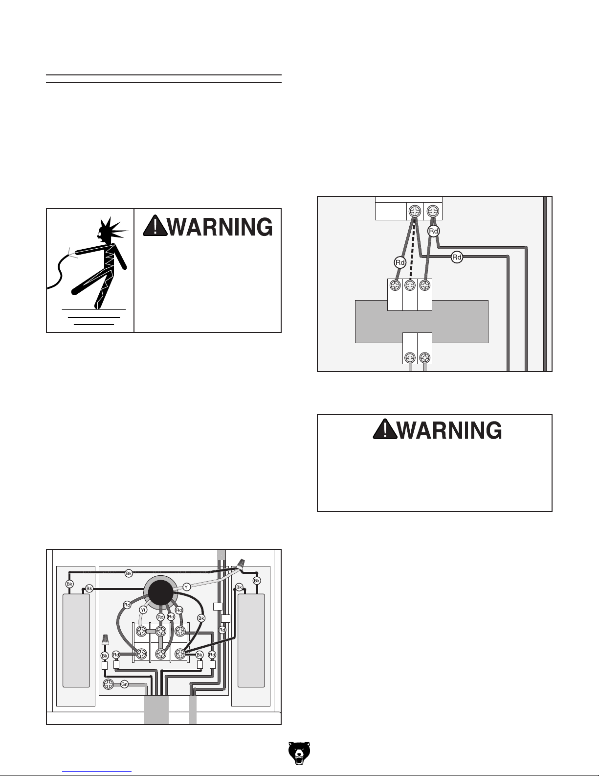
3. Remove the wire from the Z2 terminal and
terminate it with a wire cap and electrical tape
(see Figure 3), then re-install the wiring junction box cover.
Re-Wiring the Transformer
Remove the electrical panel access cover on the
rear of the column, then move the wire from the
115V terminal on the transformer to the 230V terminal, as shown in Figure 4.
Transformer
115
0
230
Replacing the Power Switch
Record the wire connections on the 110V switch
before you remove it, then replace it with the
included 220V power switch and make the same
wire connections.
Re-Wiring the Motor
1. Remove the cover of the motor wiring junc-
tion box.
2. Re-configure the two metal terminal jumpers
so that terminals Z2 and U2 are connected
and U2 and V1 are connected, as shown in
Figure 3.
11
12
0
24
Figure 4. Electrical panel transformer configured
for 220V operation.
Covers, guards, and safety devices on
this machine are provided for your safety.
Always keep them secured in place before
connecting the machine to power to avoid
serious personal injury.
Z2
U2 V2
Z1
V1
U1
Capacitor
150M 250V
3 1
2
Ground
Figure 3. Motor configured for 220V operation.
-14-
Capacitor
4
20M 450V
G3102 /G3103 Ver tical Mill

SECTION 3: SETUP
Setup Safety
This machine presents
serious injury hazards
to untrained users. Read
through this entire manual to become familiar with
the controls and operations before starting the
machine!
Wear safety glasses during the entire setup process!
Items Needed for
Setup
The following items are needed to complete the
setup process, but are not included with your
machine:
Description Qty
• Assistant ..................................................... 1
• Safety Glasses ........................ 1 Per Person
• Solid Round High-Grade Steel Bar
5
⁄8 –3⁄4"D x 3'L or longer ............................... 1
• Fork Lift (rated for at least 1500 lbs) .......... 1
• Precision Level ........................................... 1
• Metal Shims ................................ As Needed
• Floor Mounting Hardware ........... As Needed
• Shop Rags & Cleaning Solvent . . As Needed
• Standard Screwdriver ................................. 1
• Hex Wrench 3mm ....................................... 1
• Wrench or Socket 16mm ............................ 1
The Model G3102 / G3103
is a heavy machine.
Serious personal injury
may occur if safe moving
methods are not used. To
be safe, get assistance
and use a fork lift rated
for at least 1500 lbs. to
move the shipping crate
and remove the machine
from the crate.
Unpacking
Your machine was carefully packaged for safe
transportation. Remove the packaging materials
from around your machine and inspect it. If you
discover the machine is damaged, please imme-
diately call Customer Service at (570) 546-9663
for advice.
Save the containers and all packing materials for
possible inspection by the carrier or its agent.
Otherwise, filing a freight claim can be difficult.
When you are completely satisfied with the condition of your shipment, inventory the contents.
G3102 /G3103 Ver tical Mill
-15-
 Loading...