

Page 1

WOOD LATHE COPY ATTACHMENT
MODEL G2891
INSTRUCTION MANUAL
Copyright © 1993 By grizzly industrial, inC. revised novemBer, 2009 (JB)
WARNING: NO PORTION OF THIS MANUAL MAY BE REPRODUCED IN ANY SHAPE
OR FORM WITHOUT THE WRITTEN APPROVAL OF GRIZZLY INDUSTRIAL, INC.
printed in taiWan
Page 2

This manual provides critical safety instructions on the proper setup,
operation, maintenance and service of this machine/equipment.
Failure to read, understand and follow the instructions given in this
manual may result in serious personal injury, including amputation,
electrocution or death.
The owner of this machine/equipment is solely responsible for its
safe use. This responsibility includes but is not limited to proper
installation in a safe environment, personnel training and usage
authorization, proper inspection and maintenance, manual availability
and comprehension, application of safety devices, blade/cutter integrity, and the usage of personal protective equipment.
The manufacturer will not be held liable for injury or property damage
from negligence, improper training, machine modifications or misuse.
Some dust created by power sanding, sawing, grinding, drilling, and
other construction activities contains chemicals known to the State
of California to cause cancer, birth defects or other reproductive
harm. Some examples of these chemicals are:
• Lead from lead-based paints.
• Crystalline silica from bricks, cement and other masonry products.
• Arsenic and chromium from chemically-treated lumber.
Your risk from these exposures varies, depending on how often you
do this type of work. To reduce your exposure to these chemicals:
Work in a well ventilated area, and work with approved safety equipment, such as those dust masks that are specially designed to filter
out microscopic particles.
Page 3

Table Of Contents
PAGE
1. SAFETY
SAFETY RULES FOR POWER TOOLS ................................................................ 2-3
ADDITIONAL SAFETY INSTRUCTIONS FOR LATHES .......................................... 4
2. INTRODUCTION
COMMENTARY ......................................................................................................... 5
UNPACKING ............................................................................................................. 6
PARTS INVENTORY ................................................................................................. 6
SITE CONSIDERATIONS ......................................................................................... 7
3. ASSEMBLY
OVERVIEW ............................................................................................................... 8
MOUNTING ............................................................................................................... 9
ROUGH ALIGNMENT ............................................................................................. 10
FINAL ALIGNMENT .................................................................................................11
4. ADJUSTMENTS
CABLE TENSION ................................................................................................... 12
GIB ADJUSTMENT ................................................................................................. 12
CUTTING TOOL ...................................................................................................... 13
COPY STYLUS ....................................................................................................... 13
5. OPERATIONS
OVERVIEW ............................................................................................................. 14
IMPORTANT POINTS ............................................................................................. 14
BASIC OPERATION .......................................................................................... 15-16
6. MAINTENANCE
LUBRICATION ........................................................................................................ 17
CUTTING TOOL ...................................................................................................... 17
7. CLOSURE ..................................................................................................................... 18
MACHINE DATA ..................................................................................................................... 19
PARTS DIAGRAM ................................................................................................................... 20
PARTS LIST ............................................................................................................................ 21
WARRANTY AND RETURNS ................................................................................................. 22
G2891 Lathe Copy Attachment -1-
Page 4
SECTION 1: SAFETY
For Your Own Safety Read Instruction
Manual Before Operating This Equipment
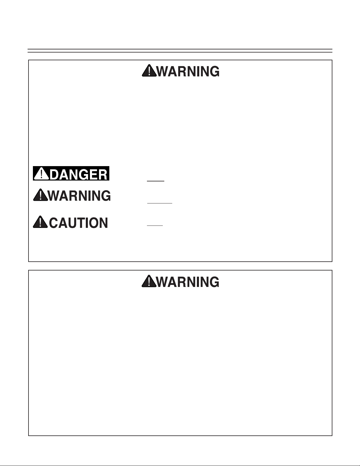
The purpose of safety symbols is to attract your attention to possible hazardous conditions. This
manual uses a series of symbols and signal words which are intended to convey the level of
importance of the safety messages. The progression of symbols is described below. Remember
that safety messages by themselves do not eliminate danger and are not a substitute for proper
accident prevention measures.
Indicates an imminently hazardous situation which, if not
avoided, WILL result in death or serious injury.
Indicates a potentially hazardous situation which, if not
avoided, COULD result in death or serious injury.
Indicates a potentially hazardous situation which, if not
avoided, MAY result in minor or moderate injury. It may also
be used to alert against unsafe practices.
This symbol is used to alert the user to useful information
NOTICE
about proper operation of the equipment.
Safety Instructions For Power Tools
1. KEEP GUARDS IN PLACE and in working
order.
2. REMOVE ADJUSTING KEYS AND
WRENCHES. Form habit of checking to
see that keys and adjusting wrenches are
removed from tool before turning on.
3. KEEP WORK AREA CLEAN. Cluttered
areas and benches invite accidents.
4. DON’T USE IN DANGEROUS
ENVIRONMENT. Don’t use power tools in
damp or wet locations, or where any flammable or noxious fumes may exist. Keep
work area well lighted.
5. KEEP CHILDREN AND VISITORS AWAY.
All children and visitors should be kept a
safe distance from work area.
6. MAKE WORK SHOP CHILD PROOF with
padlocks, master switches, or by removing
starter keys.
7. DON’T FORCE TOOL. It will do the job
better and safer at the rate for which it was
designed.
8. USE RIGHT TOOL. Don’t force tool or
attachment to do a job for which it was not
designed.
-2- G2891 Lathe Copy Attachment
Page 5
Safety Instructions For Power Tools
9. USE PROPER EXTENSION CORD. Make
sure your extension cord is in good condition. Conductor size should be in accordance with the chart below. The amperage
rating should be listed on the motor or tool
nameplate. An undersized cord will cause
a drop in line voltage resulting in loss of
power and overheating. Your extension
cord must also contain a ground wire and
plug pin. Always repair or replace extension cords if they become damaged.
Minimum Gauge for Extension Cords
LENGTH
AMP RATING 25ft 50ft 100ft
0-6 18 16 16
7-10 18 16 14
11-12 16 16 14
13-16 14 12 12
17-20 12 12 10
21-30 10 10 No
10. WEAR PROPER APPAREL. Do not wear
loose clothing, gloves, neckties, rings,
bracelets, or other jewelry which may get
caught in moving parts. Non-slip footwear
is recommended. Wear protective hair covering to contain long hair.
11. ALWAYS USE SAFETY GLASSES. Also
use face or dust mask if cutting operation
is dusty. Everyday eyeglasses only have
impact resistant lenses, they are NOT
safety glasses.
12. SECURE WORK. Use clamps or a vise to
hold work when practical. It’s safer than
using your hand and frees both hands to
operate tool.
13. DON’T OVERREACH. Keep proper foot-
ing and balance at all times.
14. MAINTAIN TOOLS WITH CARE. Keep
tools sharp and clean for best and safest
performance. Follow instructions for lubricating and changing accessories.
15. DISCONNECT TOOLS before servicing
and changing accessories, such as blades,
bits, cutters, and the like.
16. REDUCE THE RISK OF UNINTENTIONAL
STARTING. Make sure switch is in off
position before plugging in.
17. USE RECOMMENDED ACCESSORIES.
Consult the owner’s manual for recommended accessories. The use of improper
accessories may cause risk of injury.
18. CHECK DAMAGED PARTS. Before further use of the tool, a guard or other
part that is damaged should be carefully
checked to determine that it will operate
properly and perform its intended function. Check for alignment of moving parts,
binding of moving parts, breakage of parts,
mounting, and any other conditions that
may affect its operation. A guard or other
part that is damaged should be properly
repaired or replaced.
19. NEVER LEAVE TOOL RUNNING
UNATTENDED. TURN POWER OFF.
Don’t leave tool until it comes to a complete stop.
G2891 Lathe Copy Attachment -3-
Page 6
Additional Safety Instructions For The G2891
1. Before turning your lathe on, ensure
that the cutting tool is well away from
the turning square. Ensure that the turning square will rotate freely.
2. Make sure the workpiece and the tem-
plate or master spindle are securely
mounted.
3. Always start the lathe at its slowest
speed.
4. Maintain minimal play in the guide cable
and carriage.
5. To prevent excessive vibration, don’t
force the cutting tool or take too big a
cut in one pass. Recommended maximum cut is
6. Make sure cable path is unobstructed at
all times.
1
⁄16"
7. Before any copying operation, ensure
that the headstock and tailstock of your
lathe are centered on the same axis.
8. While working, position yourself so you
are within easy reach of all lathe and
Copy Attachment controls.
9. Keep base lubricated to ensure smooth
carriage movement during copying. DO
NOT lubricate the cable, it is friction
operated.
10. Do not make any adjustments to the
lathe or copy attachment while the lathe
is operating. If adjustments are necessary, turn the lathe off, unplug the power
cord and wait for the moving parts to
stop.
11. Habits - good and bad - are hard to
break. Develop good habits and safety
will become second-nature.
Like all power tools, there is danger associated with the Model G2891 Lathe Copy
Attachment. Accidents are frequently
caused by lack of familiarity or failure to
pay attention to the tool or your work. Use
this tool with respect and caution to lessen
the possibility of operator injury. If normal safety precautions are overlooked or
ignored serious personal injury may occur.
-4-
This equipment has the potential to propel debris into the air which can cause
eye injury. Always wear safety glasses
or goggles when operating equipment.
Everyday glasses or reading glasses only
have impact resistant lenses, they are not
safety glasses. Be sure your safety glasses
meet American National Standards Institute
(ANSI) standards.
No list of safety guidelines can be complete.
Every shop environment is different. Always
consider safety first, as it applies to your
individual working conditions. Failure to do
so could result in serious personal injury,
damage to equipment or poor work results.
G2891 Lathe Copy Attachment
Page 7

SECTION 2: INTRODUCTION
Commentary
Grizzly Industrial, Inc. is proud to offer the
Model G2891 Wood Lathe Copy Attachment.
The G2891 is part of Grizzly’s growing family of
fine woodworking and metalworking machinery.
When used according to the guidelines stated in
this manual, you can expect years of trouble-free,
enjoyable operation.
The Model G2891 is a wood lathe duplicator
capable of mass-producing many shapes of the
same design. The G2891 comes complete with
mounting hardware and cutting tool.
We are also pleased to provide this manual with
the Model G2891. It was written to guide you
through assembly, review safety considerations,
and cover general operating procedures. It represents our effort to produce the best documentation possible. If you have any comments regarding this manual, please write to us at the address
below:
Grizzly Industrial, Inc.
C
/O Technical Documentation
P.O. Box 2069
Bellingham, WA 98227-2069
The specifications, drawings, and photographs
illustrated in this manual represent the Model
G2891 as supplied when the manual was prepared. However, owing to Grizzly’s policy of continuous improvement, changes may be made at
any time with no obligation on the part of Grizzly.
Whenever possible, though, we send manual
updates to all owners of a particular tool or
machine. Should you receive one, we urge you to
insert the new information with the old and keep
it for reference.
To operate this, or any power tool, safely
and efficiently, it is essential to become as
familiar with its characteristics as possible.
The time you invest before you begin to use
your Model G2891 will be time well spent.
DO NOT operate this machine until you
are completely familiar with the contents
of this manual. Make sure you read and
understand all of the safety procedures. If
you do not understand something, DO NOT
operate the machine.
Most importantly, we stand behind our
machines. If you have any service questions
or parts requests, please call or write us at the
location listed below.
Grizzly Industrial, Inc.
2406 Reach Road
Williamsport, PA 17701
Phone: (570) 326-3806
Fax: (800) 438-5901
E-Mail: techsupport@grizzlyindustrial.com
Web Site: http://www.grizzlyindustrial.com
G2891 Lathe Copy Attachment -5-
Page 8
Unpacking
Parts Inventory
This Wood Lathe Copy Attachment is shipped
from the manufacturer in a carefully packed
carton. If you discover the machine is damaged
after you’ve signed for delivery, and the truck
and driver are gone, you will need to file a freight
claim with the carrier. Save the containers and all
packing materials for possible inspection by the
carrier or its agent. Without the packing materials,
filing a freight claim can be difficult. If you need
assistance determining whether you need to file
a freight claim, or with the procedure to file one,
please contact our Customer Service.
When you are completely satisfied with the condition of your shipment, you should inventory its
parts.
After all the parts have been removed from the
carton, you should have:
• Main Attachment Body
• Large Handwheel
• Hardware Box
5
Threaded, Square Mounting Plate 2
Bed Brackets 2
Handwheel Handle 1
Cutting Tool 1
Unthreaded, Rectangular Mounting Plate 2
Allen
Allen
Allen
M8-1.25 x 60mm Hex Bolt & Clamp Plate 2
M8-1.25 Hex Nut 2
3
3
In the event that any non-proprietary parts are
missing (e.g. a nut or a washer), we would be
glad to replace them, or, for the sake of expediency, replacements can be obtained at your local
hardware store.
⁄8"-11 x 21⁄2" Socket Head Cap Screw 2
®
Wrench 4mm 1
®
Wrench 5mm 1
®
Wrench 14mm 1
⁄8" Flat Washer 2
⁄8" Lock Washer 2
NOTICE
A full parts list and breakdown can be
found toward the end of this manual. For
easier assembly, or to identify missing
parts, please refer to the detailed illustrations at the end of the manual.
-6- G2891 Lathe Copy Attachment
Page 9

Site Considerations Notes
FLOOR LOAD
Your G2891, when mounted to your wood lathe,
represents a large weight load in a small footprint. Be sure that the floor in your work area is
adequately reinforced to support the weight of the
lathe and copy attachment.
WORKING CLEARANCES
Working clearances can be thought of as the
distances between machines and obstacles that
allow safe operation of every machine without
limitation. Ensure that your working area offers
plenty of room for free movement and a substantial amount of distance between you and others
that may be working in your shop space.
LIGHTING AND OUTLETS
Lighting should be bright enough to eliminate
shadows and prevent eye strain. Electrical circuits should be dedicated or large enough to
handle combined motor amp loads of the lathe
and other machinery connected to that circuit.
Outlets should be located near each machine
so power or extension cords are not obstructing
high-traffic areas. Be sure to observe local electrical codes for proper installation of new lighting,
outlets, or circuits.
Make your shop “child safe”. Ensure that
your workplace is inaccessible to youngsters by closing and locking all entrances
when you are away. Never allow visitors in
your shop when assembling, adjusting or
operating equipment.
G2891 Lathe Copy Attachment
-7-
Page 10

SECTION 3: ASSEMBLY
Overview
NOTICE
All assembly and adjustment instructions
assume that your lathe is axially aligned,
i.e., the headstock and tailstock are centered on the same axis. Consult your lathe
owner’s manual for proper procedure.
Most of your Copy Attachment has been assembled at the factory. However, you will need to
attach the handle to the carriage handwheel,
mount the longitudinal-feed handwheel and cutting tool and mount the main assembly to your
lathe.
1.1.
2.
The illustration below indicates the features
and controls included with the Model G2891.
Assembly, adjustments, operation and maintenance procedures will all be more successful
after you develop an understanding of the copy
attachment’s construction and functions.
Some metal parts may have sharp edges
(called “flashing”) on them after they are
formed. Please examine the edges of all
parts before handling them. Failure to do so
could result in skin laceration.
1. Copy Carriage Bed
2. Carriage Travel Cable
3. Cutting Tool Carriage
4. Cutting Tool Arbor
5. Mounting Brackets (2)
6. Carriage Stop
3.
4.
7. Longitudinal Handwheel
7.
8.
8. Master Spindle Support
9. Crossfeed Handwheel
10. Stylus Height Adjuster
11. Stylus
12. Quill Gap Adjuster
13. Template Support (2)
14. Spindle Support Adjuster
Figure 1. Wood Lathe Copy Attachment features and controls.
-8-
5.
6.
9.
10.
11.
12.
13.
14.
G2891 Lathe Copy Attachment
Page 11

Mounting
20%
20%
60%
The Model G2891 mounts easily on Grizzly Lathe
Models G1067Z and G1495. It will also mount on
most other lathes having a bed size of at least
40''. Two mounting brackets attach the bed of the
Model G2891 securely to the bed of the lathe.
The mounting process is as follows:
1. Mount the two bed brackets perpendicular
to the lathe bed with the large cap screws
and the square threaded mounting plates
provided. The heads of the cap screws
should be on top of the brackets and the
mounting plates should be below the bed.
Figure 3. Sliding attachment onto bolts.
To provide a solid base for the Copy
Attachment base, the mounting brackets
should be centered on points measuring
20% of the distance across the bed from
the headstock and tailstock. See Figure 2.
On a lathe with a 40" bed, brackets will be
centered approximately 8" from the headstock and tailstock. Some minor degree of
variation may be necessary to eliminate any
interference between the Copy Attachment
and the normal operation of the lathe.
The front of the brackets should cantilever
over the front of the lathe bed by about 6".
Just finger-tighten the cap screws for now.
2. Slide the two hex head bolts with clamping
plates attached into the channel located
along the bottom of the Copy Attachment
main body. See Figure 3. Place the Copy
Attachment onto the bed brackets installed
in Step 1, dropping the hex bolts through
the bed bracket slots at the front of the
lathe. Center the attachment body with the
lathe bed and slip the packing block, flat
washers, spring washers and nuts provided
over the hex bolts and just finger-tighten.
Make certain the Copy Attachment does
not block access to any of the lathe controls. Some lateral adjustment can be done
to assure clearance if necessary.
Figure 2. Attachment locations for left and right bed attachment brackets.
G2891 Lathe Copy Attachment -9-
Page 12

Rough Alignment
6"
Copy
Attachment
Bed
Once the Copy Attachment Bed is attached to the
mounting brackets, the following procedures will
allow you to begin the very important process of
aligning the parallelism between the centers of
the lathe and those of the centers which will hold
your template or original profile.
1. To roughly align the Copy Attachment
with the lathe headstock/tailstock axis two
gauge boards will be needed. The gauge
boards should be approximately 1- 1
thick, 12'' long and 3'' wide. Clamp these
gauge boards onto the lathe bed, one
under the headstock, the other under the
tailstock.
2. Place a machinist’s square on top of the
wood and measure 6'' toward the Copy
Attachment bed. See Figure 4. Place a
precise mark across the width of the wood.
Repeat the process with another piece of
wood at the headstock.
1
⁄8''
4. Tighten the large cap screws securing the
mounting brackets to the lathe bed with the
®
large Allen
wrench provided. Then tighten
the hex nuts securing the Copy Attachment
Bed to the mounting brackets.
5. Once the brackets and bed are securely
attached, remove the gauge boards.
6. Install the longitudinal-feed handwheel.
This is the larger of the two handwheels.
It mounts on the shaft at the left hand end
of the Copy Attachment Bed. Secure the
wheel with the setscrew included.
7. Attach the crossfeed handwheel handle to
the smaller wheel on the the sliding carriage.
8. Install the cutting tool into the arbor and
tighten the collar set screw. See Figure 5.
Figure 5. Securing cutting tool.
Figure 4. Use of gauge boards for alignment.
Use caution when handling the Copy
Attachment’s cutting tool. Its sharp edges
3. Once both gauges are marked, slide the
Copy Attachment bed over the board until
could cause skin lacerations if handled
improperly.
the leading edge is even with the marks on
both the left and right sides.
-10- G2891 Lathe Copy Attachment
Page 13

Final Alignment
Final alignment of the lathe axis and the copier
axis must be precise to ensure that they are both
parallel. Before executing the following steps,
mount a turning square between the centers of
your lathe.
The turning square should be as long as the
maximum center-to-center distance of your lathe
to ensure the greatest degree of accuracy. It is
critical that the turning blank is perfectly centered
and as near-perfectly straight as possible.
1. Move the carriage to one end of the Copy
Attachment and crank the cross-feed handwheel until the cutting tool nearly touches
the side of the blank. See Figure 6.
Figure 7. Using precision spacer.
very carefully adjust the bed until the cutter
is equal distant from the turning square at
both ends of its longitudinal movement.
4. Continue to test the cutter against the turn-
ing square until it is evenly spaced in relation to the turning square along its entire
length.
Figure 6. Aligning lathe to copy attachment.
2. Without changing the position of the turn-
ing blank, slowly turn the longitudinal feed
handwheel to move the carriage toward
the opposite end of the lathe. Use a feeler
gauge or another precision spacer when
starting out to ensure consistent distance
between the cutter and the turning square.
See Figure 7.
3. If the cutter does not maintain a consistent
distance from the turning square at both
ends of the cutter’s longitudinal movement,
or along it’s length, you may have to loosen
the bed from its mounting brackets and
5. Once adjustments are complete, ensure
that all mounting bolts are securely tightened.
Avoid wearing loose-fitting clothing, jewelry, or other personal items that could be
caught in moving parts of the machinery
while adjusting or operating this machine.
Serious personal injury could result if this
warning is ignored.
NOTICE
If the carriage is difficult or impossible to
move along the bed, see Gib Adjustment in
next section.
G2891 Lathe Copy Attachment -11-
Page 14

SECTION 4: ADJUSTMENTS
Cable Tension
The movement of the carriage assembly along the
body of the Copy Attachment is controlled by the
movement of the Longitudinal-Feed Handwheel.
This Handwheel is connected to the carriage
via a cable. This cable should be taut to ensure
responsive movement of the carriage.
The cable can be tightened by loosening the bolt
at the control rod. See Figure 8. The cable should
then be pulled snugly, but not so tight that stress
is placed on the cable. Once snug, re-tighten the
bolt to secure the cable.
The goal of gib adjustment is to provide as little
play as possible between the carriage and the
bed while still allowing free movement of the carriage.
There are eight adjustment locations: 2 on the
front of the carriage, 2 on the back and 4 underneath.
To adjust the gibs:
1. Loosen the lock nut(s) and and loosen or
tighten the setscrews with the 3mm Allen
wrench.
2. Slide the carriage back and forth to test
for binding and re-adjust until the carriage
travels smoothly, without binding or excess
wobble.
3. When adjustments are complete, tighten
the lock nuts while maintaining the setscrew position with the Allen
Figure 9. Re-test after tightening.
®
wrench. See
®
Figure 8. Adjusting carriage cable tension.
Gib Adjustment
The carriage slides along the Copy Attachment
bed on brass strips called gibs. These gibs are
the means by which you adjust the amount of
friction or play between the carriage and the
bed.
-12- G2891 Lathe Copy Attachment
Figure 9. Adjusting the gib tightness.
Page 15

Cutting Tool
Copy Stylus
The cutting tool can be positioned closer or farther away from the workpiece by loosening the
setscrew at the top of the cutting tool collar. Use
an 8mm Allen
ments. To install or replace the cutting tool:
1. Loosen the setscrew on the cutting tool col-
lar.
2. Insert the cutting tool with the triangular
cutting edge up. See Figure 10.
3. Tighten the setscrew.
Figure 10. Cutting tool and setscrew.
®
wrench to make collar adjust-
To ensure the greatest level of precision while
copying from a template or a master profile, it is
essential that the Copy Stylus is properly positioned at the underside of the travelling carriage.
When adjusting the stylus, keep in mind that its
follower edge should be centered on the template or master profile, so the narrowest point fits
securely within the profile. To adjust the stylus:
1. Center your master profile on the copy cen-
ters, or attach your profile template to the
attachment brackets included on the front
of the Copy Attachment body. Insert the
stylus so the rounded edge of the follower
contacts the master. See Figure 11.
2. Be sure that your template or master profile
is perfectly parallel to the Copy Attachment
bed by repeating the procedures used to
check alignment between the lathe centers
and the Copy Attachment. This time, move
the stylus from one end of the template or
master profile to the other by turning the
longitudinal handwheel. The cross-slide
handwheel will allow you to adjust the location of the stylus, so you can find points
on either end of the profile which will allow
you to ensure proper alignment. Adjust the
stylus height until the follower edge is centered on the template or profile. Tighten the
setscrew to secure the stylus.
Figure 11. Stylus follower edge.
G2891 Lathe Copy Attachment -13-
Page 16

SECTION 5: Operations
Overview
This Copy Attachment will produce any number of
duplicate spindles from one master profile or template. The advantages provided by this accessory
for your wood lathe are readily apparent, in terms
of consistency and labor savings.
While the Copy Attachment provides a substantial aid in recreating spindle profiles, keep in mind
that it is designed primarily for rough spindle
shaping. Its capacity for detail is limited by the
cutter and stylus. Final detailed turning will be
best accommodated with the use of hand-guided,
precision turning chisels.
To minimize the need for extensive hand work,
we recommend you create profiles with graceful
tapers and beads whenever possible.
• To reduce whip and vibration of relatively
narrow copy spindles, we recommend operating the longitudinal handwheel with your
left hand and backing up the spinning workpiece with your right. DO NOT attempt to
grip the workpiece too tightly while it is turning.
• If the cut you are producing is too rough,
try increasing the rotation speed of your
lathe (not to exceed the maximum recommended speed for the size of material you
are turning) and take a lighter cut. See your
lathe’s instruction manual for recommended
speeds.
• As with any other surfacing operation, we
recommend taking multiple passes, rather
than trying to remove too much wood all at
once. This is much safer and will also result
in improved cutting results.
Important Points
Because small-diameter master spindles have
the potential to bend or bow slightly when the
stylus makes contact, we recommend using a
template made from
other stable material. The master spindle profile
can be transferred to the template and carefully
cut out. The template can then be attached to the
mounting brackets located on the front side of the
Copy Attachment body. See “Stylus Adjustment”
in the Adjustment Section for details on proper
template alignment.
The following are some other important points to
consider when using your Copy Attachment:
1
/4" to 3/8-" plywood or some
• When making copies, always move the
stylus so it follows the template or master
profile “downhill”. Trying to move the stylus
“uphill” along the template will cause the
stylus and cutter to dig into the template and
workpiece. See Figure 12 for recommended
direction of cuts.
• To avoid unnecessary waste of expensive
premium materials, we strongly recommend
you turn a test piece before attempting duplication on your finish material. Make adjustments as required.
• You can save time during duplication by
removing the corners from all of the spindles
you plan on creating before activating the
Copy Attachment. You will need to make
the cuts with a lathe chisel on your tool rest,
prior to installing the Copy Attachment.
-14- G2891 Lathe Copy Attachment
Page 17

Master Spindle or Template
Stylus
Move from high points towards
areas with greater depth of cut
Figure 12. Recommended direction of stylus travel.
Lathe Centerline
Copy Attachment
Centerline
Cutting Tool
Follower Stylus
Basic Operation
To make a copy of an existing spindle or
template:
1. To make identical copies from a master
spindle it is necessary to first make certain
the cutting tool and the follower stylus are
aligned with their respective centerlines.
See Figure 13. This can be done most easily by mounting turning squares with identical dimensions on the lathe centers and
on the Copy Attachment centers. Move the
follower stylus so it just touches the square.
Adjust the cutting tool in or out of the holder
so it also just touches the square. Remove
the turning squares.
2. Mount the workpiece between the lathe
centers.
3. Move the carriage with the longitudinal
handwheel until the tip of the cutter is precisely located at the point on the workpiece
where you want the turning action to begin.
See Figure 12.
4. If you are using a template, spread the tem-
plate-mounting brackets apart to accommodate the template. Note that you will have
to drill holes in your template to mount it
to the template mounting brackets. Locate
the position of the template on the Copy
Attachment main body so the profile will
line up with the desired location of the profile on the workpiece. If you followed Step
2, the stylus should line up at the starting
point of the template.
5. Adjust the crosswheel until the stylus comes
in contact with the template in its desired
position.
6. If duplicating an existing spindle, mount
the spindle between the master spindle
carriers. First position and lock the head
center so the existing spindle profile will
line up with the intended profile area on the
copy. Use a 13mm wrench to loosen and
tightening the mounting fasteners. Slide the
tail center so it is just outside of the master
spindle, and lock in place. Hold the master
spindle in position and tighten the hand
knob located on the tail center.
Figure 13. Stylus/Cutting Tool alignment.
G2891 Lathe Copy Attachment -15-
Make sure that the workpiece is firmly seated between centers. If it becomes unseated
from the lathe at operating speed, the workpiece will be propelled from the machine.
Serious personal injury will occur to anyone
in the path of the workpiece.
Page 18

7. Move the carriage stylus to the left hand
limit of the profiled area and adjust the left
hand stop until it is in contact with the carriage. See Figure 14. Tighten the stop with
®
a Phillips
head screwdriver.
8. Repeat the procedure for the right hand
stop.
pass. If it tends to bite or gouge the work-
piece, back the cutter slightly and try again.
Be conservative when removing stock.
13. After you’ve made several passes with the
cutting tool, turn the lathe off and inspect
the results. It should not be tapered. If it is,
the Copy Attachment is not properly aligned
to the axis of the wood lathe. Re-align the
attachment, according to the instructions in
the Assembly and Adjustment Sections and
re-try with a new test cut.
14. If you are satisfied, continue to remove
material from the workpiece, using the
“downhill” cutting method shown earlier.
Remember, trying to cut “uphill” will likely
result in chipping and gouging. Don’t do it.
15. Continue removing stock until the workpiece is complete. See Figure 15.
Figure 14. Adjusting positive stops.
9. Once the template and the workpiece are
both securely in place, loosen the cutter in
its collar and adjust it until both the cutter
and the stylus are just touching the workpiece evenly and the template evenly. It
is essential for accurate copying that the
cutter tip and the tip of the stylus always
remain at the same positions in relation to
the workpiece and the master profile. Slide
the carriage away from the workpiece, so
both the stylus and cutter are well away
from your work.
10. Ensure that everything is secure and turn
on the lathe at its slowest speed. Slowly
advance the cutting tool toward the left
edge of the workpiece. Once contact is
made, advance the cutting tool into the
1
copy spindle approximately
/16". Turn the
longitudinal handwheel so the carriage
travels from stop to stop.
Figure 15. Shaping the copy spindle.
16. After completing the initial copy, continue
following these procedures until all the
spindles are completed.
17. When all spindles are complete, remove
the Copy Attachment and replace it with
the lathe’s tool post.
11. After each pass, extend the cutter another
1
/16" (maximum) and repeat with another
pass. Repeat this process until the stylus
18. Use appropriate lathe chisels to sharpen
details and smooth the turned surfaces of
each copy. Sand smooth.
comes in contact with the template.
12. Watch the tool carefully as you make each
-16- G2891 Lathe Copy Attachment
Page 19

SECTION 6: MAINTENANCE
Lubrication
After each copying session, wipe the lathe and
Copy Attachment with a clean cloth to remove
accumulated chips and sawdust.
1. Apply a light spray lubricant to the longitudi-
nal and crossfeed gears.
2. To prevent rust and corrosion, apply an
occasional coating of carnauba paste wax
to the bed and other non-painted surfaces.
3. Above all else, keep the entire Copy
Attachment, as well as the wood lathe,
clean and free of accumulated dirt and
grime that could impede free movement of
the carriage, cutter, stylus or other working
parts.
Cutting Tool
After extended use, particularly with hardwoods
or woods with large amounts of oil or resins, the
cutter may become dull.
When you notice that the cutter seems to be
working abnormally hard while cutting, or if overheating or frequent gouging and chipping occur,
you will need to either sharpen or replace the cutting tool. Loosen the collar setscrew and remove
the tool, and sharpen or replace as needed.
Cutting tools will become very hot when
in use. Use care when removing a cutting
tool which has just been used. It can still
be extremely hot and cause painful burns.
Wear gloves, or wait for the tool to cool
down before removing or adjusting.
Never allow visitors into your shop while
assembling, operating, or maintaining tools
and machinery. Keep your shop child-safe
by locking up securely when not in use,
and by providing proper supervision when
children are present.
G2891 Lathe Copy Attachment -17-
Page 20

SECTION 7: CLOSURE
The following pages contain general machine
data, parts diagrams/lists, troubleshooting guide
and Warranty/Return information for your Model
G2891 Lathe Copy Attachment.
If you need parts or help in assembling your
machine, or if you need operational information, we encourage you to call our Service
Department. Our trained service technicians will
be glad to help you.
If you have comments dealing specifically with
this manual, please write to our Bellingham,
Washington location using the address in Section
2 Introduction. The specifications, drawings, and
photographs illustrated in this manual represent
the Model G2891 as supplied when the manual
was prepared. However, due to Grizzly’s policy
of continuous improvement, changes may be
made at any time with no obligation on the part
of Grizzly. Whenever possible, though, we send
manual updates to all owners of a particular tool
or machine. Should you receive one, add the
new information to this manual and keep it for
reference.
We recommend you keep a copy of our current catalog for complete information regarding
Grizzly's warranty and return policy. If you need
additional technical information relating to this
machine, or if you need general assistance or
replacement parts, please contact the Service
Department listed in Section 2: Introduction.
Additional information sources are necessary to
realize the full potential of this machine. Trade
journals, woodworking magazines, and your local
library are good places to start.
The Model G2891 was specifically designed
for use with 40" Wood Lathes. DO NOT
MODIFY AND/OR USE THIS MACHINE FOR
ANY OTHER PURPOSE. Modifications or
improper use of this tool will void the warranty. If you are confused about any aspect
of this machine, DO NOT use it until you have
answered all your questions. Serious per-
sonal injury may occur.
We have included some important safety measures that are essential to this machine’s operation. While most safety measures are generally
universal, Grizzly reminds you that each workshop is different and safety rules should be considered as they apply to your specific situation.
Operating this equipment has the potential to propel debris into the air which can
cause eye injury. Always wear safety glasses or goggles when operating equipment.
Everyday glasses or reading glasses only
have impact resistant lenses, they are not
safety glasses. Be certain the safety glasses you wear meet the appropriate standards of the American National Standards
Institute (ANSI).
Like all power tools, there is danger associated with the Model G2891 Copy Attachment.
Accidents are frequently caused by lack
of familiarity or failure to pay attention.
Use this tool with respect and caution to
lessen the possibility of operator injury. If
normal safety precautions are overlooked
or ignored, serious personal injury may
occur.
-18- G2891 Lathe Copy Attachment
Page 21

MACHINE DATA
SHEET
Customer Service #: (570) 326-3806 • To Order Call: (800) 523-4777 • Fax #: (800) 438-5901
GRIZZLY MODEL G2891
WOOD LATHE COPY ATTACHMENT
Design Type:
Drive .......................................................................................Manual, Cable-Operated
Wood Lathe Compatibility .......... 14" Swing Over Bed with Cast or Channel Bedways
Copy Pattern ........................................................Existing Spindle or Plywood Pattern
Overall Dimensions:
Length ...................................................................................................................52
Width ..................................................................................................................... 16
Depth ....................................................................................................................... 7
Shipping Weight ..................................................................................................68 lbs.
Net Weight...........................................................................................................60 lbs.
Box Size ..................................................................................... 55" L x 18" W x 10" H
Capacities:
Maximum Copy Length ............................................................................................36"
Maximum Total Depth of Cut ......................................................................................2"
Maximum Original Spindle Diameter .........................................................................3"
Maximum Recommended Cutting Depth per Pass ..................................................
Height of Cutting Tool Above Bedway ..................................................................... 6
Construction:
Body ...............................................................................Extruded Aluminum and Steel
Duplicating Head and Mounting Brackets .......................................................Cast Iron
Cutter .................................................................................................High Speed Steel
3
⁄8"
1
⁄8"
5
⁄8"
1
⁄16"
3
⁄4"
Specifications, while deemed accurate, are not guaranteed.
G2891 Lathe Copy Attachment -19-
Page 22

-20- G2891 Lathe Copy Attachment
Page 23

G2891 PARTS LIST
Ref. # Part # Description Ref. # Part # Description
1
2
3
4
5
6
9
10
11
12
13
13-1
14
15
16
17
18
19
20
21
22
23
24
25
26
27
28
29
30
31
32
33
34
35
36
37
P2891001 Cutting Tool
P2891002 Cutting Tool Collar
PSS21M Setscrew M8-1.25 x 25
P2891004 Arbor
PS14M Phillips
®
M6-1.0 x 12
PLW04M Lock Washer 8mm
PSB26M Cap Screw M6-1.0 x 12
PSS04M Setscrew M6-1.0 x 12
PN01M Hex Nut M6-1.0
P2891012 Front Mounting Plate
P2891013 Brass Packing Sheet
P2891013-1 Brass Packing Sheet
PSS03M Setscrew M6-1.0 x 8
PSS20M Setscrew M6-1.25 x 8
P2891016 Pulley
PR07M Retaining Ring 18mm
P2891018 Cable
PB03M Hex Bolt M8-1.25 x 16
P2891020 Spring
PN03M Hex Nut M8-1.25
P2891022 Feed Panel Label
P2891023 Carriage Block
PSB42M Cap Screw M6-1.0 x 85
P2891025 Control Rod
P2891026 Special Head Bolt
PSS04M Setscrew M6-1.0 x 12
P2891028 Carriage Stop Clip
P2891029 Front Spindle Rail
P2891030 Main Body
P2891031 Shaft Sleeve
P2891032 Spindle Plate
PLW04M Lockwasher 8mm
PS15M Phillips
®
M5-0.8 x 15
P2891035 Copying Block
PSB43M Cap Screw M6-1.0 x 38
PSS03M Setscrew M6-1.0 x 8
38
39
40
41
42
43
44
45
46
47
48
49
50
51
52
53
54
55
56
57
58
59
60
62
63
64
65
68
69
70
71
77
78
79
83
84
P2891038 Spindle Rod
P2891039 Stylus
PSB27 Cap Screw
P2891041 Support Bracket
PB08M Hex Bolt M6-1.0 x 20
PS02 Phillips
® 1
/4”-20 x 3/4”
P2891044 Left Sleeve
P2891045 Rear Spindle Rail
P2891046 Steel Tube
P2891047 Control Shaft Sleeve
PSS21M Setscrew M8-1.25 x 25
P2891049 Longit. Feed Handwheel
PR11M Retaining Ring 25mm
P2891051 Head Center
P2891052 Center Post
P2891053 Control Screw
PN09M Hex Nut M12-1.75
P2891055 Cross-slide Handwheel
P2891056 Clamping Plate
P2891057 Packing Sheet
P2891058 Sleeve
P2891059 Template Support Bracket
PS16M Phillips
®
M8-1.25 x 16
PW02 Flat Washer –
PLW04 Lock Washer –
PB28M Hex Bolt M8-1.25 x 60
PB28M Hex Bolt M8-1.25 x 60
P2891068 Packing Block
PB07M Hex Bolt M8-1.25 x 25
P2891070 Right Sleeve
P2891071 Adjustment Shaft
P2891077 Tail Center
P2891078 Center Sleeve
P2891079 Knob
P2891083 Copy Block Plate
P2891084 Mounting Plate
5
/8”-11x 21/2”
3
/8"
3
/8"
5
/8" - 11
G2891 Lathe Copy Attachment -21-
Page 24

Page 25

Grizzly Industrial, Inc. warrants every product it sells for a period of 1 year to the original purchaser from
the date of purchase. This warranty does not apply to defects due directly or indirectly to misuse, abuse,
negligence, accidents, repairs or alterations or lack of maintenance. This is Grizzly’s sole written warranty
and any and all warranties that may be implied by law, including any merchantability or fitness, for any particular purpose, are hereby limited to the duration of this written warranty. We do not warrant or represent
that the merchandise complies with the provisions of any law or acts unless the manufacturer so warrants.
In no event shall Grizzly’s liability under this warranty exceed the purchase price paid for the product and
any legal actions brought against Grizzly shall be tried in the State of Washington, County of Whatcom.
We shall in no event be liable for death, injuries to persons or property or for incidental, contingent, special,
or consequential damages arising from the use of our products.
To take advantage of this warranty, contact us by mail or phone and give us all the details. We will then
issue you a “Return Number,’’ which must be clearly posted on the outside as well as the inside of the
carton. We will not accept any item back without this number. Proof of purchase must accompany the
merchandise.
The manufacturers reserve the right to change specifications at any time because they constantly strive to
achieve better quality equipment. We make every effort to ensure that our products meet high quality and
durability standards and we hope you never need to use this warranty.
Please feel free to write or call us if you have any questions about the machine or the manual.
Thank you again for your business and continued support. We hope to serve you again soon.
WARRANTY AND RETURNS
Page 26

CUT ALONG DOTTED LINE
Name _____________________________________________________________________________
Street _____________________________________________________________________________
City _______________________ State _________________________ Zip _____________________
Phone # ____________________ Email ________________________ Invoice # _________________
Model # ____________________ Order # _______________________ Serial # __________________
WARRANTY CARD
The following information is given on a voluntary basis. It will be used for marketing purposes to help us develop
better products and services. Of course, all information is strictly confidential.
1. How did you learn about us?
____ Advertisement ____ Friend ____ Catalog
____ Card Deck ____ Website ____ Other:
2. Which of the following magazines do you subscribe to?
3. What is your annual household income?
____ $20,000-$29,000 ____ $30,000-$39,000 ____ $40,000-$49,000
____ $50,000-$59,000 ____ $60,000-$69,000 ____ $70,000+
4. What is your age group?
____ 20-29 ____ 30-39 ____ 40-49
____ 50-59 ____ 60-69 ____ 70+
5. How long have you been a woodworker/metalworker?
____ 0-2 Years ____ 2-8 Years ____ 8-20 Years ____20+ Years
6. How many of your machines or tools are Grizzly?
____ 0-2 ____ 3-5 ____ 6-9 ____10+
7. Do you think your machine represents a good value? _____ Yes _____No
8. Would you recommend Grizzly Industrial to a friend? _____Yes _____No
9. Would you allow us to use your name as a reference for Grizzly customers in your area?
Note: We never use names more than 3 times. _____ Yes _____No
10. Comments: _____________________________________________________________________
_________________________________________________________________________________
_________________________________________________________________________________
_________________________________________________________________________________
____ Cabinetmaker & FDM
____ Family Handyman
____ Hand Loader
____ Handy
____ Home Shop Machinist
____ Journal of Light Cont.
____ Live Steam
____ Model Airplane News
____ Old House Journal
____ Popular Mechanics
____ Popular Science
____ Popular Woodworking
____ Precision Shooter
____ Projects in Metal
____ RC Modeler
____ Rie
____ Shop Notes
____ Shotgun News
____ Today’s Homeowner
____ Wood
____ Wooden Boat
____ Woodshop News
____ Woodsmith
____ Woodwork
____ Woodworker West
____ Woodworker’s Journal
____ Other:
Page 27

TAPE ALONG EDGES--PLEASE DO NOT STAPLE
FOLD ALONG DOTTED LINE
FOLD ALONG DOTTED LINE
GRIZZLY INDUSTRIAL, INC.
P.O. BOX 2069
BELLINGHAM, WA 98227-2069
Place
Stamp
Here
Name_______________________________
Street_______________________________
City______________State______Zip______
Send a Grizzly Catalog to a friend:
Page 28

Buy Direct and Save with Grizzly® – Trusted, Proven and a Great Value!
~Since 1983~
ORDER
24 HOURS A DAY!
1-800-523-4777
Visit Our Website Today For
Current Specials!
 Loading...