


6" X 47" HEAVY-DUTY JOINTER
MODEL G1182HW / G1182ZHW / G1182Z / G1182ZX
INSTRUCTION MANUAL
COPYRIGHT ©2000 BY GRIZZLY INDUSTRIAL, INC.
WARNING: NO PORTION OF THIS MANUAL MAY BE REPRODUCED IN ANY SHAPE
OR FORM WITHOUT THE WRITTEN APPROVAL OF GRIZZLY INDUSTRIAL, INC.
JANUARY, 2002 PRINTED IN TAIWAN.
G1182Z
G1182ZHW
G1182HW
G1182ZX

WARNING
Some dust created by power sanding, sawing, grinding,
drilling, and other construction activities contains chemicals known to the State of California to cause cancer,
birth defects or other reproductive harm. Some examples
of these chemicals are:
• Lead from lead-based paints.
• Crystalline silica from bricks, cement, and other
masonry products.
• Arsenic and chromium from chemically treated
lumber.
Your risk from these exposures varies, depending on
how often you do this type of work. To reduce your exposure to these chemicals: work in a well ventilated area,
and work with approved safety equipment, such as those
dust masks that are specially designed to filter out microscopic particles.

G1182 6" Series Jointers -1-
G1182 Series Jointers
Terms and Definitions
G1182ZHW
Description
G1182HW G1182Z G1182ZX
Stand
Switch
Table Adjustment
Motor
Dust Collection
Weight
Cabinet
Toggle On / Off
Hand Wheels
1 H.P.
Chip Chute
215 lbs.
Steel Stand
Toggle On / Off
Hand Wheels
1 H.P.
Chip Chute
215 lbs.
Cabinet
Toggle On / Off
Levers
1 H.P.
225 lbs.
Heavy-Duty Cabinet
Magnetic w/ Light
Levers
1 H.P.
235 lbs.
Infeed Table: The infeed table is the table where
the cutting operation begins. When facing the
front of the jointer, it is on the right hand side.
The wood travels right to left; from the infeed
table, across the cutterhead, and onto the outfeed table.
Outfeed Table: The outfeed table is the table
where the cutting operation ends. When facing
the front of the jointer, it is on the left hand side.
Cutterhead: The cutterhead is the cylindrical
assembly that holds each of the three jointer
knives. It spins on a horizontal axis between
the infeed and outfeed table, and is covered by
the cutterhead guard when the jointer is not in
use.
Fence: The jointer fence is the adjustable cast
iron surface that the wood stock runs along
when jointing and surface planing. The fence is
adjustable from 45° to 90° to the infeed and
outfeed tables.
Adjustment Levers and Handwheels: Controls
the height of the infeed and outfeed tables.
Table Lock Handles: The threaded handles that
must be loosened before the height of the
tables can be adjusted. They are then tightened after the height is properly set.
Rabbet Cut: A rabbet cut is a groove cut along
the long edge of the wood stock. This cut is
typically used in carcass construction. The cutterhead guard must be removed for this operation so great care is needed for safe operation.
Surface Planing: Surface planing is running the
face of the wood stock over the jointer. This
provides one flat side that is ready to be run
through a dedicated planing machine.
Edge Jointing: Edge jointing is running the long
edge of the wood stock over the jointer. This
provides one flat edge that is ready to be run
against the table saw rip fence or edge glued.
Cutterhead Guard: The metal guard that covers
the cutterhead when wood stock is not passing
over the jointer.
Chip Chute With
Dust Hood
Chip Chute With
Dust Hood

-2- G1182 6" Series Jointers
Table Of Contents
PAGE
1. SAFETY
WARNINGS ............................................................................................................3
SAFETY RULES FOR ALL TOOLS ........................................................................4
ADDITIONAL SAFETY INSTRUCTIONS FOR JOINTERS ....................................5
2. CIRCUIT REQUIREMENTS
110V OPERATION ..................................................................................................6
GROUNDING ..........................................................................................................6
EXTENSION CORDS ..............................................................................................6
3. INTRODUCTION
COMMENTARY........................................................................................................7
UNPACKING ............................................................................................................8
PIECE INVENTORY..............................................................................................8-9
CLEAN UP ............................................................................................................10
SITE CONSIDERATIONS ......................................................................................10
4. ASSEMBLY
BEGINNING ASSEMBLY ......................................................................................11
STAND ..............................................................................................................11-13
JOINTER TO STAND ............................................................................................13
V-BELT ..................................................................................................................14
FENCE ..................................................................................................................14
CUTTERHEAD GUARD ........................................................................................15
BELT GUARD ........................................................................................................15
KNIFE SETTING GAUGE ......................................................................................16
PEDESTAL SWITCH ............................................................................................16
5. ADJUSTMENTS
TABLE GIBS ..........................................................................................................17
KNIVES ............................................................................................................17-19
OUTFEED TABLE ............................................................................................19-20
INFEED TABLE ......................................................................................................20
90˚ FENCE STOP ..................................................................................................21
45˚ FENCE STOP ............................................................................................21-22
6. OPERATIONS
TEST RUN ............................................................................................................23
STOCK INSPECTION ..........................................................................................23
EDGE JOINTING ..................................................................................................24
BEVELING ............................................................................................................24
SURFACE PLANING ............................................................................................25
RABBETING ..........................................................................................................25
7. MAINTENANCE
GENERAL ............................................................................................................26
TABLES ................................................................................................................26
LUBRICATION ......................................................................................................26
V-BELT ..................................................................................................................26
8. CLOSURE ..................................................................................................................27
MACHINE DATA ..............................................................................................................28
PARTS BREAKDOWN AND PARTS LISTS ..............................................................29-36
TROUBLESHOOTING GUIDE ..........................................................................................37
WARRANTY AND RETURNS ..........................................................................................38

G1182 6" Series Jointers -3-
Safety Instructions For Power Tools
SECTION 1: SAFETY
5. KEEP CHILDREN AND VISITORS
AWAY. All children and visitors should be
kept a safe distance from work area.
6. MAKE WORKSHOP CHILD PROOF with
padlocks, master switches, or by removing
starter keys.
7. DO NOT FORCE TOOL. It will do the job
better and safer at the rate for which it was
designed.
8. USE RIGHT TOOL. Do not force tool or
attachment to do a job for which it was not
designed.
1. KEEP GUARDS IN PLACE and in working
order.
2. REMOVE ADJUSTING KEYS AND
WRENCHES. Form habit of checking to
see that keys and adjusting wrenches are
removed from tool before turning on.
3. KEEP WORK AREA CLEAN. Cluttered
areas and benches invite accidents.
4. DO NOT USE IN DANGEROUS ENVIRONMENT. Do not use power tools in
damp or wet locations, or where any flammable or noxious fumes may exist. Keep
work area well lighted.
For Your Own Safety Read Instruction
Manual Before Operating This Equipment
Indicates an imminently hazardous situation which, if not avoided,
WILL result in death or serious injury.
Indicates a potentially hazardous situation which, if not avoided,
COULD result in death or serious injury.
Indicates a potentially hazardous situation which, if not avoided,
MAY result in minor or moderate injury. It may also be used to alert
against unsafe practices.
This symbol is used to alert the user to useful information about
proper operation of the equipment.
The purpose of safety symbols is to attract your attention to possible hazardous conditions. This
manual uses a series of symbols and signal words which are intended to convey the level of
importance of the safety messages. The progression of symbols is described below. Remember
that safety messages by themselves do not eliminate danger and are not a substitute for proper
accident prevention measures.
NOTICE

-4- G1182 6" Series Jointers
9. USE PROPER EXTENSION CORD. Make
sure your extension cord is in good condition. Conductor size should be in accordance with the chart below. The amperage
rating should be listed on the motor or tool
nameplate. An undersized cord will cause
a drop in line voltage resulting in loss of
power and overheating. Your extension
cord must also contain a ground wire and
plug pin. Always repair or replace extension cords if they become damaged.
Minimum Gauge for Extension Cords
10. WEAR PROPER APPAREL. Do not wear
loose clothing, gloves, neckties, rings,
bracelets, or other jewelry which may get
caught in moving parts. Non-slip footwear
is recommended. Wear protective hair covering to contain long hair.
11. ALWAYS USE SAFETY GLASSES. Also
use face or dust mask if cutting operation is
dusty. Everyday eyeglasses only have impact
resistant lenses, they are NOT safety glasses.
12. SECURE WORK. Use clamps or a vise to hold
work when practical. It’s safer than using your
hand and frees both hands to operate tool.
13. DO NOT OVERREACH. Keep proper foot-
ing and balance at all times.
14. MAINTAIN TOOLS WITH CARE. Keep
tools sharp and clean for best and safest
performance. Follow instructions for lubricating and changing accessories.
15. USE RECOMMENDED ACCESSORIES.
Consult the owner’s manual for recommended accessories. The use of improper
accessories may cause risk of injury.
LENGTH
AMP RATING 25ft 50ft 100ft
0-6 18 16 16
7-10 18 16 14
11-12 16 16 14
13-16 14 12 12
17-20 12 12 10
21-30 10 10 No
Safety Instructions For Power Tools
16. REDUCE THE RISK OF UNINTENTIONAL STARTING. On machines with mag-
netic contact starting switches there is a
risk of starting if the machine is bumped or
jarred. Always disconnect from power
source before adjusting or servicing. Make
sure switch is in OFF position before reconnecting.
17. MANY WOODWORKING TOOLS CAN
“KICKBACK” THE WORKPIECE toward
the operator if not handled properly. If you do
not understand what kickback is, or how to
prevent it, Do Not operate this machine.
18. CHECK DAMAGED PARTS. Before fur-
ther use of the tool, a guard or other part
that is damaged should be carefully
checked to determine that it will operate
properly and perform its intended function.
Check for alignment of moving parts, binding of moving parts, breakage of parts,
mounting, and any other conditions that
may affect its operation. A guard or other
part that is damaged should be properly
repaired or replaced.
19. NEVER LEAVE TOOL RUNNING UNATTENDED. TURN POWER OFF. Do not
leave tool until it comes to a complete stop.
20. NEVER OPERATE A MACHINE WHEN
TIRED, OR UNDER THE INFLUENCE OF
DRUGS OR ALCOHOL. Full mental alert-
ness is required at all times when running
a machine.
21. NEVER ALLOW UNSUPERVISED OR
INEXPERIENCED PERSONNEL TO
OPERATE THE MACHINE. Make sure
any instructions you give in regards to
machine operation are approved, correct,
safe, and clearly understood.
22. IF AT ANY TIME YOU ARE EXPERIENCING DIFFICULTIES performing the intend-
ed operation, stop using the machine!
Then contact our service department or
ask a qualified expert how the operation
should be performed.

G1182 6" Series Jointers -5-
No list of safety guidelines can be complete.
Every shop environment is different. Always
consider safety first, as it applies to your
individual working conditions. Use this and
other machinery with caution and respect.
Failure to do so could result in serious personal injury, damage to equipment or poor
work results.
Additional Safety Instructions For Jointers
1. JOINTING SAFETY BEGINS with your
lumber. Inspect your stock carefully before
you feed it over the cutterhead. If you have
any doubts about the stability or structural
integrity of your stock, DO NOT JOINT IT!
2. MAINTAIN PROPER RELATIONSHIPS of
infeed and outfeed table surfaces and cutterhead knife path.
3. ALWAYS USE A PUSH BLOCK when
jointing. Never place your hands directly
over the cutterhead.
4. SUPPORT THE WORKPIECE adequately
at all times during operation, maintain control over the work at all times.
5. WHEN JOINTING, do not stand directly at
the end of either table. Position yourself
just to the side of the infeed table to avoid
possible kickbacks.
6. NEVER MAKE JOINTING CUTS deeper
than
1
⁄8".
7. NEVER JOINT A BOARD that has loose
knots. All defects should be cut out of the
board before it is planed or jointed.
8. NEVER JOINT end grain.
9. JOINT WITH THE GRAIN. Jointing against
the grain is dangerous and could produce
chatter or excessive chip out.
10. WITH THE EXCEPTION OF RABBETING,
all operations must be performed with the
guard in place. After rabbeting, be sure to
replace the guard.
11. NEVER BACK THE WORK toward the
infeed table.
12. HABITS – GOOD AND BAD – are hard to
break. Develop good habits in your shop
and safety will become second-nature to
you.
13. “KICKBACK” is when the workpiece is
thrown off the jointer table by the force of
the cutterheads. Always use pushblocks
and safety glasses to reduce the likelihood
of injury from “kickback.” If you do not
understand what kickback is, or how it
occurs, Do Not operate this machine.
14. BE AWARE THAT CERTAIN WOODS MAY
CAUSE AN ALLERGIC REACTION in peo-
ple and animals, especially when exposed
to fine dust. Make sure you know what type
of wood dust you will be exposed to and
always wear an approved respirator.
-6- G1182 6" Series Jointers
110V Operation
SECTION 2: CIRCUIT REQUIREMENTS
A 15 amp fuse or circuit breaker should be used
when fusing this (tool description). Circuit breakers rated any higher may not be adequate to protect the circuit from power surges.
If you find it necessary to use an extension cord
with the Model G1182 series of jointers, make
sure the cord is rated Hard Service (grade S) or
better. Refer to the chart in the standard safety
instructions to determine the minimum gauge for
the extension cord. The extension cord must also
contain a ground wire and plug pin. Always repair
or replace extension cords when they become
worn or damaged.
Extension Cords
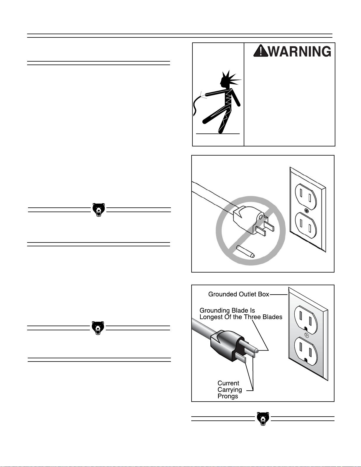
Grounding
This equipment must be
grounded. Verify that any
existing electrical outlet
and circuit you intend to
plug into is actually
grounded. Under no circumstances should the
grounding pin from any
three-pronged plug be
removed. Serious injury
may occur.
In the event of an electrical short, grounding
reduces the risk of electric shock by providing
electric current a path of least resistance. This
tool is equipped with a power cord having an
equipment-grounding conductor. See Figure 1.
The outlet must be properly installed and grounded in accordance with all local codes and ordinances.
The Model G1182 Jointer Series is wired for
110/120V, single- phase operation. The 1 H.P.
motor is dual voltage; however, we do not recommend converting to 220V because the magnetic
switch is only rated for 110V. The motor will safely draw 14 amps at 110V. If you operate this
machine on any circuit that is already close to its
capacity, it might blow a fuse or trip a circuit
breaker. However, if an unusual load does not
exist and a power failure still occurs, contact a
qualified electrician or our service department.
Figure 1. Typical 110V 3-prong plug and outlet.
Figure 1A. Do not remove grounding pin.

G1182 6" Series Jointers -7-
SECTION 3: INTRODUCTION
We are proud to offer these four models of the
Model G1182 6" Jointer. These machines are part
of a growing Grizzly family of fine woodworking
machinery. When used according to the guidelines set forth in this manual, you can expect
years of trouble-free, enjoyable operation and
proof of Grizzly’s commitment to customer satisfaction.
The Model G1182 Jointer Series all feature 1 H.P.
TEFC motors driving a three-knife cutterhead at
5000 R.P.M. The knives are high speed steel,
resharpenable, and are adjusted by means of jack
screws or springs, making blade setting quick and
easy. The infeed and outfeed tables are ground
cast iron and are mounted on dovetailed ways
with adjustable gibs.
Depending upon the model you selected, table
height is adjustable by means of levers or handwheels. The operator controls on the Model
G1182ZX are conveniently mounted on a
pedestal above the tables. The Z-Series models
incorporate a one piece cabinet style stand and a
dust hood for easy connection to a dust collection
system.
We are also pleased to provide this universal
manual covering all of the G1182 models. It was
written to guide you through assembly, review
safety considerations, and cover general operating procedures. It represents our effort to produce
the best documentation possible. If you have any
comments regarding this manual, please write to
us at the address below:
Grizzly Industrial, Inc.
C
/O Technical Documentation
P.O. Box 2069
Bellingham, WA 98227-2069
The specifications, drawings, and photographs
illustrated in this manual represent the Model
G1182 series jointers as supplied when the manual was prepared. However, owing to Grizzly’s
policy of continuous improvement, changes may
be made at any time with no obligation on the part
of Grizzly. Whenever possible, though, we send
manual updates to all owners of a particular tool
or machine. Should you receive one, we urge you
to insert the new information with the old and keep
it for reference.
Commentary
Read the manual before
assembly and operation. Become familiar
with the machine and its
operation before beginning any work. Serious
personal injury may
result if safety or operational information is not
understood or followed.
Most importantly, we stand behind our machines.
If you have any service questions or parts
requests, please call or write us at the location
listed below.
Grizzly Industrial, Inc.
1203 Lycoming Mall Circle
Muncy, PA 17756
Phone: (570) 546-9663
Fax: (800) 438-5901
E-Mail: techsupport@grizzly.com
Web Site: http://www.grizzly.com
-8- G1182 6" Series Jointers
Unpacking Piece Inventory
NOTICE
A full parts list and breakdown can be found
toward the end of this manual. For easier
assembly, or to identify specific parts,
please refer to the detailed illustrations at
the end of the manual.
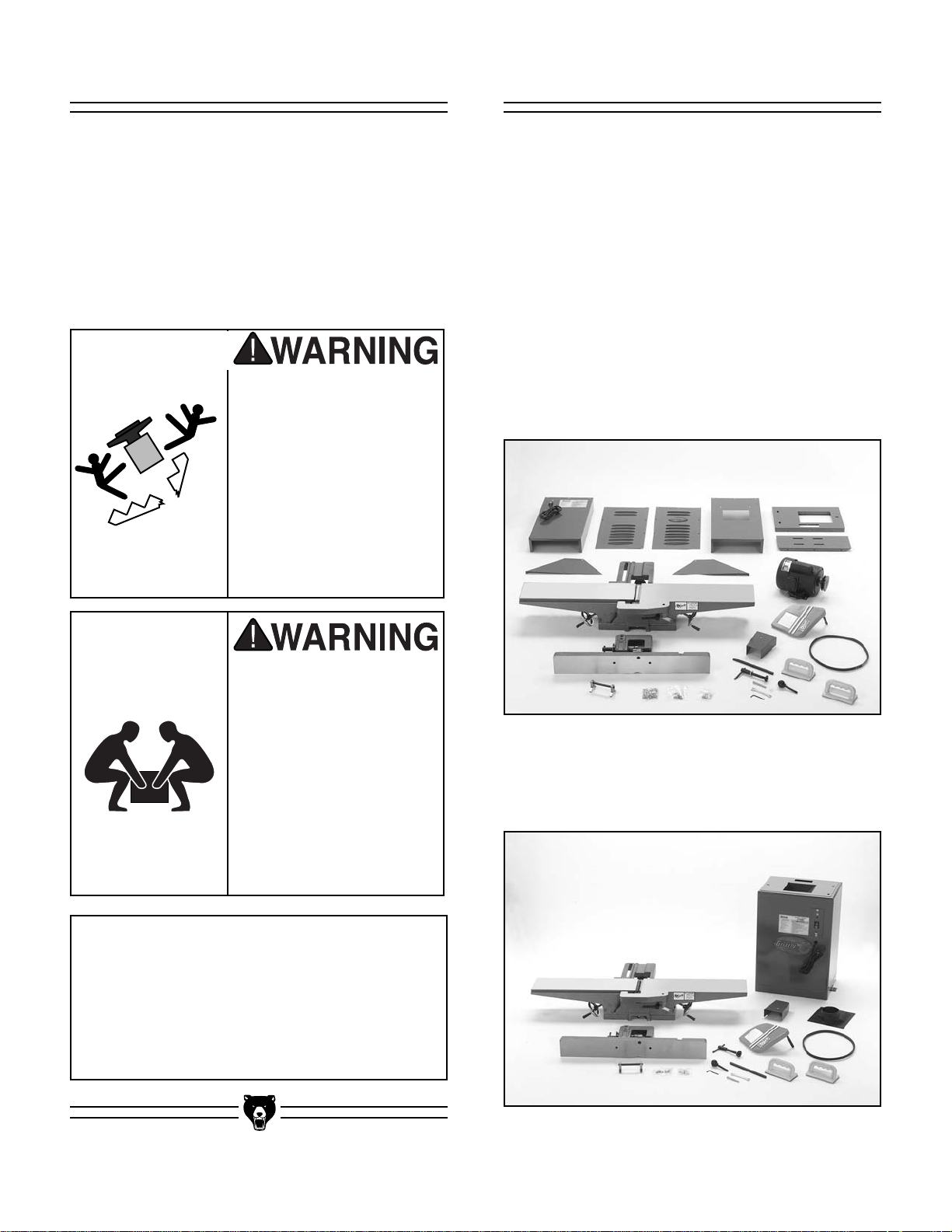
Model G1182HW (Figure2A)
• Jointer Assembly
• Fence Assembly
• Stand Assembly
• Hardware
-Hex Bolts 3⁄8" - 16 x 3⁄4"3
-Lock Washers
3
⁄8"3
-Allen
®
Wrench 3mm 1
-V-Belt 1
-Knife Setting Jig 1
-Hand Wheels 2
-Knob 1
-Locking Screw 1
-Flat Washer
1
⁄2" 1
-Special Nut 1
If moving this machine
up or down stairs, the
machine must be dismantled and moved in smaller
pieces. Make sure floor
and stair structures are
capable of supporting the
combined weight of the
machine parts and the
people moving them.
The Model G1182 series is shipped from the
manufacturer in a carefully packed carton. If you
discover the machine is damaged after you’ve
signed for delivery, immediately call Customer
Service for advice.
When you are completely satisfied with the condition of your shipment, you should inventory its
parts.
The G1182 series is a
heavy machine, 235 lbs.
shipping weight. DO
NOT over-exert yourself
while unpacking or
moving your machine –
you will need assistance. Serious personal
injury may occur if safe
moving methods are not
followed.
Figure 2A. G1182HW layout.
Figure 2B. G1182HW layout.
Model G1182HW (Figure 2B)
Same as above except the stand assembly is
replaced by a one piece cabinet stand.
G1182 6" Series Jointers -9-
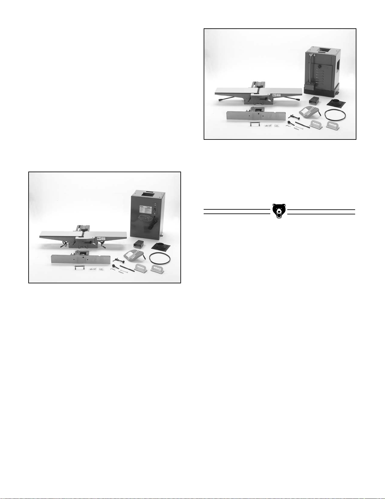
Model G1182ZX (Figure 2D)
Same as G1182Z above except the on/off switch
is replaced by a pedestal mounted electrical
switch assembly.
In the event that any non-proprietary parts are
missing (e.g. a nut or a washer), we would be glad
to replace them, or, for the sake of expediency,
replacements can be obtained at your local hardware store.
Model G1182Z (Figure 2C)
• Jointer Assembly
• Fence Assembly
• Stand Assembly
• Dust Hood
• Hardware
-Hex Bolts 3⁄8" - 16 x 3⁄4"3
-Lock Washers
3
⁄8"3
-Allen
®
Wrench 3mm 1
-V-Belt 1
-Knife Setting Jig 1
-Tilt Lever 1
-Knob 1
-Locking Screw 1
-Flat Washer
1
⁄2" 1
-Special Nut 1
Figure 2C. G1182Z layout.
Figure 2D. G1182ZX layout.
-10- G1182 6" Series Jointers
Site Considerations
FLOOR LOAD
Your Model G1182 series jointer represents a
moderate weight load in a small footprint. Most
commercial or home shop floors should be sufficient to carry the weight. If you question the
strength of your floor, you may wish to check with
an architect or structural engineer in your area to
make certain it can handle the load.
WORKING CLEARANCES
Working clearances can be thought of as the distances between machines and obstacles that
allow safe operation of every machine without limitation. Consider existing and anticipated machine
needs, size of material to be processed through
each machine, and space for auxiliary stands
and/or work tables. Also consider the relative
position of each machine to one another for efficient material handling. Be sure to allow yourself
sufficient room to safely run your machines in any
foreseeable operation.
LIGHTING AND OUTLETS
Lighting should be bright enough to eliminate
shadow and prevent eye strain. Electrical circuits
should be dedicated or large enough to handle
combined motor amp loads. Outlets should be
located near each machine so power or extension
cords are not obstructing high-traffic areas. Be
sure to observe local electrical codes for proper
installation of new lighting, outlets, or circuits.
Clean Up
The unpainted surfaces are coated with a waxy oil
to protect it from corrosion during shipment.
Remove this protective coating with a solvent
cleaner or citrus-based degreaser such as
Grizzly’s G7895 Degreaser. Avoid chlorine-based
solvents as they may damage painted surfaces
should they come in contact. Always follow the
usage instructions on the product you choose for
clean up.
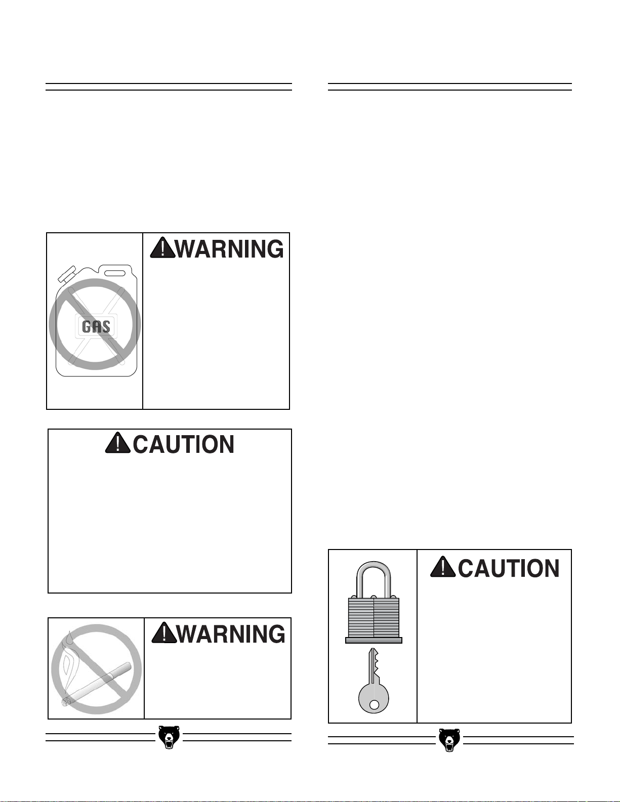
Many of the solvents commonly used to
clean machinery can be toxic when inhaled
or ingested. Always work in well-ventilated
areas far from potential ignition sources
when dealing with solvents. Use care when
disposing of waste rags and towels to be
sure they do not create fire or environmental hazards. Keep children and animals
safely away when cleaning and assembling
this machine.
Do not smoke while using
solvents. A risk of explosion or fire exists and may
be the result serious personal injury may occur.
Make your shop “child
safe.” Ensure that your
workplace is inaccessible
to youngsters by closing
and locking all entrances
when you are away. Never
allow visitors in your shop
when assembling, adjusting or operating equipment.
Do not use gasoline or
other petroleum-based
solvents. They have low
flash points which make
them extremely flammable. A risk of explosion
and burning exists if
these products are
used. Serious personal
injury may occur if this
warning is ignored.
G1182 6" Series Jointers -11-
SECTION 4: ASSEMBLY
Beginning Assembly
Most of your Model G1182 6'' Jointer has been
assembled at the factory, but some parts must be
assembled or installed after delivery. We have
organized the assembly process into steps.
Please follow along in the order presented here.
TOOLS REQUIRED: You will need a high quality
square, a long straightedge, 10mm, 12mm and
14mm open end wrenches, and a 3mm Allen
®
wrench.
Stand (G1182HW)
For reference, assemble the stand so the dust
chute end is on your left when facing the stand,
and the power switch is on your right.
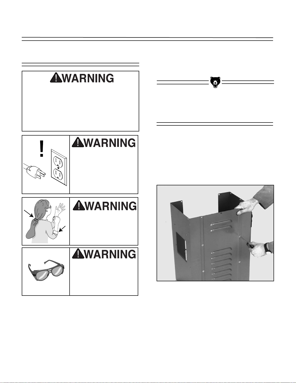
1. Begin by attaching the two ends to the front
panel with the machine screws and washers
provided. See Figure 3.
2. Mount the two dust chute sides to the dust
chute end as shown in Figure 4. Note that the
flanges are pointed away from the inside of
the chute. Do not fully tighten the screws yet.
Figure 3. Attachment of the two end panels.
All die-cut metal parts have a sharp edge
(called “flashing”) on them after they are
formed. This is removed at the factory.
Sometimes, though, a bit of flashing might
escape inspection. Please examine the
edges of all die-cut metal parts before handling them or serious injury may occur.
Disconnect power to the
machine when performing any maintenance,
assembly or adjustments. Failure to do this
may result in serious
personal injury.
Keep loose clothing
rolled up and out of the
way of machinery and
keep hair pulled back.
Wear safety glasses
during the entire assembly process. Failure to
comply may result in
serious personal injury.

-12- G1182 6" Series Jointers
3. Position the dust chute base between the dust
chute sides (flanges up), carefully aligning the
screw holes in the base and the sides. See
Figure 4 and 5. The flanges should be inside
the chute.
Figure 5. Attaching the dust chute base.
4. Attach the top of the stand to the sides and
dust chute. Note that the flanges for the top
are inside the stand (the flanges for the dust
chute opening should be outside the dust
chute, however) and that the opening for the
drive belt is at the rear of the stand. See
Figure 6.
5. Turn the stand upside down to mount the
motor to the underside of the dust chute.
Mount the motor on the chute using the four
5
⁄16" - 18 x 3⁄4" hex head bolts, flat washers and
nuts provided. Be sure to position the motor
pulley to the rear (open end) of the stand as
shown in Figure 7. Leave the motor mount
bolts finger-tight for now.
Figure 6. Attaching the top of the stand.
Figure 7. Attaching the motor.
NOTICE
Make sure the slots in the motor support are
toward the top of the stand.
Figure 4. Attaching the dust chute.

G1182 6" Series Jointers -13-
6. The power switch is already installed on the
right hand panel of the stand. To complete the
wiring, it is first necessary to remove the
switch assembly from the stand. Remove the
two Phillips® head screws holding the metal
mounting plate to the stand. The entire switch
can then be pulled out of the stand.
7. Turn the stand upright and securely tighten all
fasteners on the stand and dust chute.
This step will require at least two people. To
mount the jointer to the stand:
1. Lift the main unit onto the stand, making sure
to position the cutterhead pulley over the slot
in the top of the stand.
2. Carefully align the mounting holes in the
stand with the threaded holes in the base of
the jointer. Secure the jointer to the stand
using the three
3
⁄8" - 16 x 3⁄4" hex bolts and 3⁄8"
flat washers provided. Be sure not to overtighten
Jointer to Stand
Stand (G1182Z, ZX & ZHW)
The stand for the Z-Series models are pre-assembled.
The jointer main unit is
very heavy – you will
need assistance when
lifting it onto the stand.
Serious personal injury
may occur if safe moving methods are not followed.

-14- G1182 6" Series Jointers
Figure 8. Motor mounts inside dust chute.
Figure 9. Pulley and V-belt alignment.
1. Loosen the motor mount bolts located inside
the dust chute and slide the motor up until
you can attach the V-Belt to the pulleys. See
Figure 8.
V-Belt
Fence
2. Allow the weight of the motor to rest against
the V-Belt and lightly tighten one motor
mount bolt. For the time being, this will be
adequate belt tension.
3. Align the motor and cutterhead pulleys with
each other using a plumb bob or straightedge. Move the motor until the face of the
motor pulley is aligned with the cutterhead
pulley and tighten the motor mount bolts.
Pulley alignment can be fine tuned by loosening the motor pulley setscrews and mov-
ing the pulley in or out as necessary. See
Figure 9.
4. Check belt tension by pinching the belt
halfway between the pulleys with moderate
pressure. The amount of flex between the
pinched portions of the belt should be
approximately 1". Loosen the motor mount
bolts slightly and adjust the motor down to
increase belt tension. Tighten motor mount
bolts and recheck tension and pulley alignment.
Place the fence body on the fence support, mak-
ing sure that it fits over the key. See Figure 10.
Insert the locking screw and thread on the special
nut provided. The flange on the special nut
should protrude upward when installed correctly.
Figure 10. Fence support mechanism.
DO NOT slide the fence across the outfeed
table. Scratching will result.
Key
Locking Screw
Special Nut
(Not In Sight)
NOTICE
Setscrews
Bearing
Block
Cutterhead
Cutterhead
Pulley
Motor
Pulley
Setscrews

G1182 6" Series Jointers -15-
1. The cutterhead guard pivot shaft is slotted
on the end. This slot fits over the tang at the
end of a spring located in the spring housing.
See Figure 11. Look down the pivot hole to
get an idea where this tang is located.
2. Remove the setscrew from the slotted end of
the pivot shaft. Rotate the spring housing
counter-clockwise approximately 1 turn.
Insert the guard shaft into the pivot hole, lining up the slot with the tang.
3. The cutterhead guard shaft should fit all the
way inside the pivot hole when properly
engaged with the spring tang and should
hold the guard against the fence.
4. The cutterhead guard should be held firmly
against the fence, completely cover the cutterhead, and move back into position when
released. If this has not been achieved,
repeat Steps 2-3, increasing the number of
turns on the spring housing to 1
1
⁄2. Re-install
the setscrew into the end of the pivot shaft.
Figure 11. Spring housing.
Insert the 5⁄16" - 18 x 21⁄2" mounting bolt through
the belt guard and attach to the jointer base cast-
ing. Do not over tighten. See Figure 12.
Figure 12. Belt guard attachment.
DO NOT attempt any step of assembly,
adjustments, or maintenance while your
Model G1182 is running. Ensure that the
switch is off, power is disconnected and
moving parts have stopped before making
adjustments. Failure to comply may result
in serious personal injury.
Cutter Guard Belt Guard

-16- G1182 6" Series Jointers
1. Insert the steel rod through the hole in each
adjuster arm until the notches for the E-clips
extend past the adjustment arms on both
sides.
2. Attach the E-clips to the notches to lock
adjustment arms onto the steel rod. The
adjustment arms are symmetrical, so the
placement is not a concern. See Figure 13.
Figure 13. Knife setting gauge.
Knife Setting Gauge Pedestal Switch
G1182ZX Only
Your jointer comes with a pedestal mounted magnetic switch for safety and convenience. Simply
bolt the pedestal to the two mounting holes on the
back side of the stand with the supplied washers
and bolts.
See Figure 13A.
Figure 13A. Mounting pedestal switch to stand.

G1182 6" Series Jointers
-17-
Table Gibs
SECTION 5: ADJUSTMENTS
The function of the gibs are to allow precise
adjustment of the table movement along the
dovetail ways. Adjustment of the gib will dictate
how easy it will be to move the tables up and
down with the levers or handwheels. To adjust
gibs:
1. Unscrew the upper and lower check nuts on
the infeed table several turns, leaving the lock
handle tight. See Figure 14.
2. With one hand securely on the lever bar,
loosen the table lock handle and adjust the
KNIFE INSPECTION
The knives of your jointer must be periodically
replaced or adjusted. Adjustments should be as
precise as possible with tolerances within .002".003" to prolong the sharpness of the knife edges.
Improperly adjusted knives can unbalance the
cutterhead and shorten bearing life, as well as
produce substandard jointing or planing results.
The knives are set at the factory using jack screws
upper and lower gib setscrews until table
movement is smooth and controlled.
3. Once the gib has been properly adjusted,
tighten check nuts and repeat Steps 1-2 for
the outfeed table.
4. Make sure there is no side-to-side movement
of the tables once the check nuts have been
tightened. If there is, repeat Steps 1-4.
Figure 14. Location of check nuts.
Check Nuts
Lock Handle
Setscrews
Knives
Always lock the table with the table lock
before using the jointer. If this step is not
observed, the table could slide down while
the jointer is operating. Serious personal
injury may occur.
These knives are extremely sharp. Never
grab the cutterhead directly to rotate it.
Always use the drive pulley. Always be sure
the jointer is disconnected from its power
source before you make any adjustments.
Serious personal injury may occur.
Disconnect power to the
machine when performing any maintenance,
assembly or adjustments. Failure to do this
may result in serious
personal injury.
Keep loose clothing
rolled up and out of the
way of machinery and
keep hair pulled back.
Wear safety glasses
during the entire adjustment process. Failure
to comply may result in
serious personal injury.

-18- G1182 6" Series Jointers
before shipping. Springs are also included in the cutterhead supplied with your machine. They may be
used instead of the jack screws depending on your
preference. Now is a good time to double-check the
knife settings. To inspect and adjust knife set:
1. Unplug the jointer!
2. Remove the upper cover or cutterhead guard to
expose the top of the cutterhead.
3. Carefully turn the cutterhead (using the pulley) until
the first knife is at top dead center.
4. Using the knife setting gauge, check the knife
height. The jig should sit solidly with both feet on
the cutterhead. See Figure 15. If the knife is
adjusted properly, the contact point at the center of
each adjuster should just touch the tip of the knife.
If the knife does not make contact, or if the knife
causes the adjuster’s legs to not seat on the cutterhead, the knives need to be adjusted.
Remember, jointer knives are extremely
sharp. Use care when handling during
removing or installing.
Springs
Jack
Screws
Knife Setting
Gauge
ADJUSTMENTS USING JACK SCREWS
When using jack screws, it is not necessary to
install the springs. The knives are locked into the cutterhead with wedge-type gibs and gib bolts. Jack
screws under the knives allow fine tuning to help in the
setting process. To realign the knives:
1. Unplug the jointer!
2. Loosen the gib bolts until the knife is loose in the
slot. The gib bolts turn clockwise to loosen and
counterclockwise to tighten (when facing the head
of the bolt). See Figure 16 and 16B.
3. Place the knife setting gauge on the cutterhead as
described previously, so the feet are securely
planted on the cutterhead.
4. Adjust the screws below each end of the knife until
both feet of the gauge rest evenly on the cutterhead and the knife is just touching the bottom of
the middle foot of the gauge. The gauge will set
the knives at a uniform protrusion of approximately .070" above the cutterhead. The knife height
should vary no more than .002"-.003" across the
length of the cutterhead.
5. Maintain a constant pressure on the gauge while
retightening the gib bolts.
6. Repeat the same procedure on the remaining
knives. As mentioned before, the standard knife
setting gauge is satisfactory for reasonably accurate knife setting tasks.
Figure 15 shows the location of the springs
should you decide to use them instead of jack
screws.
Figure 16 shows the parts of the cutterhead.
Knife
Jack Screw
Gib Bolt
Gib

G1182 6" Series Jointers -19-
ADJUSTMENTS USING SPRINGS.
The knives are locked into the cutterhead with wedgetype gibs and gib bolts. Jack screws under the knives
may be substituted with springs to help in the setting
process. When using springs, it is advised that the jack
screws be removed. To realign the knives:
1. Unplug the jointer!
2. Loosen the gib bolts until the knife is loose in the
slot. The gib bolts turn clockwise to loosen and
counterclockwise to tighten (when facing the head
of the bolt). Remove the knife and jack screws.
Place 1 spring in each of the two holes in bottom of
the knife slot. See Figure 16A and 16B.
3. Place the knife setting gauge on the cutterhead as
described previously, so the feet are securely
planted on the cutterhead. Make sure the gauge
extension rod is parallel to the cutterhead to maintain accuracy.
4. The downward pressure provided by the gauge
will set the knives at a uniform protrusion of approximately .070" above the cutterhead. The knife
height should vary no more than .002"-.003"
across the length of the cutterhead.
5. Maintain a constant pressure on the gauge while
retightening the gib bolts.
6. Repeat the same procedure on the remaining
knives. As mentioned before, the standard knife
setting gauge is satisfactory for reasonably accurate knife setting tasks.
Figure 16A shows the location of the springs.
Outfeed Table
Facing the fence, the outfeed table is located to
the left of the cutterhead. The outfeed table must
be aligned to the highest point of the arc of the
blades. If it is set too high, the board will hit the
front edge of the table and be impossible to feed
over the jointer. If the table is set too low, the
back end of the board will fall into the cutterhead
and snipe will occur.
1. Loosen the table stop bolt jam nut under the
outfeed table. Turn the table stop bolt
counter-clockwise several times so that it will
not interfere when setting the correct table
height. See Figure 17.
2. Rotate the cutterhead by turning the motor
pulley. DO NOT grab the cutterhead itself.
Bring one blade to the approximate apex of its
arc.
3. Position a steel straightedge on the outfeed
table. Extend the straightedge over the middle
of the cutterhead. See Figure 18.
NOTICE
Model G1182HW uses handwheels for out-
feed and infeed table adjustments.
Knife
Spring
Gib Bolt
Gib
Figure 16B. Tightening the gib bolts.
Tighten
Loosen
Knife
Gib Bolt
Gib

-20- G1182 6" Series Jointers
Figure 18. Illustrates the use of a straightedge
to ensure proper outfeed adjustment.
4. Loosen the table lock handle and raise or
lower the table with the lever until the straightedge barely touches one of the knives. Rock
the cutterhead to ensure that the blade is at
the highest point of its arc. Check the other
two blades in the same manner. If they do not
all touch the straightedge evenly, they are not
at the same height. You must reset the knives.
Be sure to test the height at both ends of the
cutter knives. The knives must be parallel to
the table surface.
5. Adjust the stop bolt until it touches the cast
base. Tighten the table lock handle.
6. Tighten the checknut, loosen the table lock
handle, and move the table down with the
lever – then up against the stop. Check the
accuracy of the stop setting with a straightedge over the cutterhead and fine tune if necessary.
1. Loosen the jam nut and unscrew the table
stop bolt out 3 or 4 turns. See Figure 19.
2. Place a straightedge on the outfeed table so it
hangs over the infeed table. Turn the cutter-
head so that the knives are NOT touching the
straightedge.
3. Loosen the infeed table lock handle. Raise the
infeed table until it just touches the straightedge. Tighten the table lock handle.
4. Turn the stop bolt until it makes contact with
the base casting.
5. Tighten the jam nut, loosen the table lock han-
dle, and move the table up and down to check
your settings. Align the depth of cut scale to
read zero.
Infeed Table
Figure 19. Location of the infeed table stop
bolt and jam nut.
Figure 17. Table stop bolt and check nut.

G1182 6" Series Jointers -21-
1. Place a square on the outfeed table fairly
close to the cutterhead. See Figure 20.
Figure 20. Use of square to align fence.
2. Loosen the fence lock handle and the check-
nut on the positive stop bolt. Turn the bolt
against the tab until the fence contacts the
edge of the square evenly.
3. Tighten the checknut on the stop bolt and tilt
the fence forward, then back against the
stop. See Figure 21.
90° Fence Stop
Figure 21. Location of the fence’s positive stop
bolt.
4. Re-check with the square. Tightening the
checknut will move the stop bolt slightly, so
some trial-and-error may be necessary to
perfect your settings.
The fence can be tilted to 45° by loosening the
lock handle, lifting up the 90° positive stop tab,
and moving the fence in the desired direction. To
set the 45° tab stop:
1. Loosen checknut and lower fence until it
rests on the stop bolt. See Figure 22.
2. Using a bevel gauge set to 45°, place the
heel of the bevel on the outfeed table and the
blade against the fence.
45° Fence Stop
DO NOT attempt any adjustments while
your Model G1182 is running. Ensure that
the switch is off, power is disconnected and
moving parts have stopped before making
adjustments. Serious personal injury may
occur.
Figure 22. Location of stop bolt and stop tab.
Stop Tab
Stop Bolt

-22- G1182 6" Series Jointers
3. If there is a gap between the bevel’s blade
and the face of the fence, turn the stop bolt
until the gap is gone.
4. Tighten jam nut. Move your fence forward,
then back against the stop. Recheck the stop
bolt.
Figure 23. Jointer fence in 45° stop position.
Jointer knives are dangerously sharp. Use
extreme caution when handling knives or
working near them. Serious personal injury
may occur.

G1182 6" Series Jointers -23-
SECTION 6: OPERATIONS
Once assembly is complete and adjustments are
done to your satisfaction, you are ready to test
run the machine.
Turn on the power supply at the main panel.
Press the START button. Make sure that your finger is poised on the STOP button, just in case
there’s a problem. The jointer should run smoothly, with little or no vibration or rubbing noises.
Strange or unnatural noises should be investigated and corrected before operating the machine
further.
If you cannot easily locate the source of an
unusual noise or vibration, contact our service
department for help.
If the stock has large or loose knots, consider
finding another workpiece. Knots in a workpiece
can be dangerous to the operator, as well as
destructive to equipment.
Test Run
Stock Inspection
Figure 24. Correct and incorrect grain align-
ment to cutterhead.
When jointing, always cut with the grain rather
than against it. Cutting against the grain (going
against the pattern of the wood’s growth rings)
chips the wood instead of cutting it, making the
workpiece rough and irregular. Look at the side of
your board. If the direction of the grain structure
facing the cutterhead runs toward the cutterhead
as it sits on the infeed table, your cut will be with
the grain. See Figure 24.
Occasionally, you will find woods that defy all
rules. In those rare cases, it is best to feed the
workpiece slowly and take several shallow cuts.
A few extra passes will hurt much less than a
ruined workpiece.
Disconnect power to the
machine when performing any maintenance,
assembly or adjustments. Failure to do this
may result in serious
personal injury.
Keep loose clothing
rolled up and out of the
way of machinery and
keep hair pulled back.
Wear safety glasses
during the entire operation process. Failure to
comply may result in
serious personal injury.
CORRECT
ROTATION
OUTFEED TABLE
FEED DIRECTION
INFEED TABLE
INCORRECT
ROTATION
OUTFEED TABLE
FEED DIRECTION
INFEED TABLE

-24- G1182 6" Series Jointers
The purpose of edge jointing is to produce a finished, flat-edged surface that is suitable for joinery or finishing. It is also a necessary step prior to
ripping stock to width on a table saw or radial arm
saw.
1. Make sure the fence is set to 90°. Double
check it now with a try square or machinist’s
square.
2. Inspect stock for soundness and grain direc-
tion.
3. If the board is bowed (curved), place the
concave edge down on the infeed table.
4. Holding the stock firmly against the fence
and table, feed the stock slowly and evenly
over the cutterhead. See Figure 25.
Figure 25. Operator position for edge jointing.
Edge Joining
Beveling
Beveling an edge is essentially the same operation as edge jointing, except that the fence is tilted to a specified angle. Use extra care to ensure
that the edge makes solid contact with the infeed
and outfeed tables at all times.
1. Use a bevel gauge to determine the desired
angle. Then use the bevel to transfer this
angle to the fence.
2. Tilt the fence by loosening the lock handle
and moving the fence to the desired angle.
3. Inspect stock for soundness and grain direc-
tion.
4. Slowly and evenly feed stock through the
cutterhead. Make sure the face of the stock
is completely flat against the fence and the
edge is making solid contact on the infeed
and outfeed tables. See Figure 26.
5. Achieving the full bevel will probably take
several passes. Remember not to take more
than
1
⁄16" in one pass.
Figure 26. Fence position for bevel jointing.

G1182 6" Series Jointers -25-
Surface Planing Rabbet Cuts
The purpose of planing on a jointer is to produce
one flat surface. The theory behind this is that
once you have one flat surface on a board, it can
then more readily be milled to precise, final
dimensions on a thickness planer. It is nearly
impossible to surface plane both sides of a board
effectively because the two surfaced sides will
not be parallel to each other.
1. Inspect your lumber for soundness and grain
direction.
2. If the stock is cupped (warped), place the
concave side down and slowly feed it over
the cutterhead. See Figure 27.
3. Inspect your results. Most likely, many pass-
es will be necessary before your lumber has
a flat surface.
4. If the stock has large or loose knots, consid-
er finding another workpiece. Knots in a
workpiece can be dangerous to the operator,
as well as destructive to equipment.
Figure 27. Correct method for surface planing.
A rabbet is a groove cut along the edge of a
board. It is usually made to accept another board
to form a strong, simple joint. Note: The maxi-
mum rabbet depth is
1
⁄2".
1. Unplug the jointer and remove the cutter-
head guard.
2. Loosen the fence and slide it to the rabbeting
edge. Set the fence to the desired width of
the rabbet and lock down. For small rabbets,
remove the fence sliding locking lever and
reinsert it in the rear fence hole on the fence
base.
3. Inspect stock for soundness and grain direc-
tion.
4. Place stock on the infeed table and rabbet
table with the edge to be rabbeted firmly
against the fence.
5. Slowly and evenly feed stock through the
cutterhead. Using the
1
⁄16" rule, it will take six
passes to achieve a common
3
⁄8" rabbet. See
Figure 28.
6. Replace the guard when finished with rab-
beting operations.
Figure 28. Correct operator position for rabbet
cutting.
Always use push paddles when planing the
surface of a board. Failure to comply may
result in serious personal injury.

-26- G1182 6" Series Jointers
SECTION 7: MAINTENANCE
Lubrication
V-Belt
General
Tables
Regular periodic maintenance on your Model
G1182 Jointer will ensure its optimum performance. Make a habit of inspecting your jointer
each time you use it. Check for the following conditions and repair or replace when necessary.
1. Loose mounting bolts.
2. Worn switch.
3. Worn or damaged cords and plugs.
4. Damaged V-belt.
5. Any other condition that could hamper the
safe operation of this machine.
The table and other non-painted surfaces on the
Model G1182 should be protected against rust
and pitting. Wiping the jointer clean after every
use ensures that wood dust isn’t allowed to trap
moisture against bare metal surfaces.
Some woodworkers recommend using automotive paste wax on exposed steel and cast iron
surfaces. The wax provides a layer of protection,
as well as reducing friction between lumber and
the table, making cuts faster and smoother. Avoid
waxes that contain silicone or other synthetic
ingredients. These materials can find their way
into lumber that’s being worked, and can make
staining and finishing difficult. If you use paste
wax, make sure that it’s 100% Carnauba wax.
Inspect regularly for tension and wear; replace
when necessary with a size A-36 belt. Check pulleys to ensure that they are properly aligned. See
pulley/V-belt sections for proper tension and pulley alignment procedures.
Since all bearings are shielded and permanently
lubricated, simply leave them alone until they
need to be replaced. Do not lubricate them.
Table ways and the fence assembly should not
be lubricated. If the tables appear to be stuck, disassemble and clean any foreign materials from
the ways. Re-assemble and reset the gibs.
Disconnect power to the
machine when performing any maintenance,
assembly or adjustments. Failure to do this
may result in serious
personal injury.
Wear safety glasses during the entire maintenance process. Failure
to comply may result in
serious personal injury.
Keep loose clothing
rolled up and out of the
way of machinery and
keep hair pulled back.

G1182 6" Series Jointers -27-
The following pages contain general machine
data, parts diagrams/lists, troubleshooting guide
and Warranty/Return information for your Model
G1182.
If you need parts or help in assembling your
machine, or if you need operational information,
we encourage you to call our Service Department.
Our trained service technicians will be glad to help
you.
If you have comments dealing specifically with
this manual, please write to our Bellingham,
Washington location using the address in Section
3 Introduction.
We have included some important safety measures that are essential to this machine’s operation. While most safety measures are generally
universal, Grizzly reminds you that each workshop is different and safety rules should be considered as they apply to your specific situation.
We recommend you keep a copy of our current
catalog for complete information regarding
Grizzly's warranty and return policy. If you need
additional technical information relating to this
machine, or if you need general assistance or
replacement parts, please contact the Service
Department listed in Section 3 Introduction.
Additional information sources are necessary to
realize the full potential of this machine. Trade
journals, woodworking magazines, and your local
library are good places to start.
SECTION 8: CLOSURE
The Model G1182 was specifically designed
for jointing operation. DO NOT MODIFY
AND/OR USE THIS MACHINE FOR ANY
OTHER PURPOSE. Modifications or
improper use of this tool will void the warranty. If you are confused about any aspect
of this machine, DO NOT use it until all your
questions have been answered. Serious
personal injury may occur.
Like all power tools, there is danger associated with the Model G1182. Accidents are
frequently caused by lack of familiarity or
failure to pay attention. Use this tool with
respect and caution to lessen the possibility of operator injury. If normal safety precautions are overlooked or ignored, serious personal injury may occur.
Operating this equipment has the potential
for flying debris to cause eye injury. Always
wear safety glasses or goggles when operating equipment. Everyday glasses or reading glasses only have impact resistant lenses, they are not safety glasses. Be certain
the safety glasses you wear meet the appropriate standards of the American National
Standards Institute (ANSI).

-28- G1182 6" Series Jointers
Design Type ......................................................................................................Floor Model
Capacities:
Maximum Depth of Cut..............................................................................................
1
⁄2"
Maximum Width of Cut ..............................................................................................6"
Cutterhead Speed......................................................................................5000 R.P.M.
Cuts Per Minute ..................................................................................................15000
Overall Dimensions:
Table Size..................................................................................................6" W x 47" L
Height G1182HW / G1182ZHW (from floor to Table) ..........................................30
1
⁄2"
Height G1182Z / G1182ZX....................................................................................31
1
⁄4"
Overall Length ..........................................................................................................47"
Overall Width ............................................................................................................20"
Net Weight G1182HW / G1182ZHW ................................................................205 lbs.
Net Weight G1182Z ..........................................................................................215 lbs.
Net Weight G1182ZX........................................................................................225 lbs.
Construction:
Table................................................................................................................Cast Iron
Fence Assembly..............................................................................................Cast Iron
Body Assembly................................................................................................Cast Iron
Base ................................................................................Sheet Metal Stand Assembly
Cutterhead ......................................................3 Knife Slots w/ Shielded Ball Bearings
Guard ....................................................................................................Die Cast Metal
Knives ......................................................................................Jack-screw Adjustable
Motor:
Type ............................................................................TEFC Capacitor Start Induction
Horsepower..........................................................................................................1 H.P.
Phase Type ⁄ Voltage ..........................................................Single Phase; 110V/200V
Amps ......................................................................................................................14/7
Cycle ⁄ R.P.M. ............................................................................60 Hertz/3450 R.P.M.
Switch G1182HW / G1182ZHW / G1182Z ..................................Toggle Safety Switch
Switch G1182ZX ........................................................Magnetic Contactor - 110V Only
Power Transfer.............................................................................................. Belt Drive
Bearings ........................................................Shielded & Permanently Lubricated Ball
Features:
Fence..............................................................................Positive Stops at 45° and 90°
Table Movement G1182Z / G1182ZX ......................................................Lever Action
Table Movement G1182HW / G1182ZHW..............................................Hand Wheels
Infeed & Outfeed Tables ..................................................Rabbeting Capacity Built-In
Specifications, while deemed accurate, are not guaranteed.
Customer Service #: (570) 546-9663 • To Order Call: (800) 523-4777 • Fax #: (800) 438-5901
JOINTER MODELS G1182HW / G1182ZHW / G1182Z / G1182ZX
MACHINE DATA
SHEET

G1182 6" Series Jointers
-29-
09
01 PG1182001 BASE
01
PG1182HW001
BASE
(TYPE HW)
02 PG1182002 INFEED TABLE
02
PG1182HW002
INFEED TABLE
(TYPE HW)
03 PG1182003 OUTFEED TABLE
03
PG1182HW003
OUTFEED TABLE
(TYPE HW)
04 PG1182004 GIB
05 PG1182005 TABLE LOCK HANDLE
05A P102603A LOCK HANDLE
5
⁄16"
06 PSS12 SETSCREW
1
⁄4"-20 x 1"
07 PN05 HEX NUT
1
⁄4"-20
08 PG1182008 TABLE ADJUST ROD
08
PG1182HW008 TABLE ADJUST ROD
(TYPE HW)
09 PEC04M E-CLIP 13mm
10 PG1182010 BASE ROD
11 PG1182011 TABLE ADJUST BLOCK
12 PG1182012 TABLE ADJUST LEVER
13 PG1182013 KNOB
14 PG1182014 BELT GUARD
15 PW07 FLAT WASHER
5
⁄16"
16 PB23 HEX BOLT
5
⁄16"-18 x 2 1⁄2"
17 PG1182017 WARNING LABEL
REF PART # DESCRIPTION
18 PG1182018 CUTTERHEAD GUARD
18A PG1182018A STUD
20 PG1182020 SPRING PLATE
21 PG1182021 SPRING
22 PG1182022 SPRING HOUSING
23 PG1182023 HOUSING MOUNT
24 PS29 PHLP SCREW 6-32 x
5
⁄8"
25 PN02 HEX NUT
5
⁄16"-18
26 PG1182026 SCALE
27 PG1182027 POINTER
28 PG1182028 RIVET
29 PG1182029 FENCE SUPPORT
30 PB24 HEX BOLT
3
⁄8"-16 x 11⁄4"
31 PG1182031 SPECIAL WASHER
32 PG1182032 KEY
33 PRP18M ROLL PIN 4 x 12mm
34 PW02 FLAT WASHER
3
⁄8"
REF PART # DESCRIPTION
MAIN TABLES
05
08
07
06
13
09
05A
12
07
06
10
03
16
28
26
25
07
33
32
29
34
30
31
16
15
14
1
10
06
09
04
11
11
25
16
28
20
22
27
24
17
18
18A
02
21
23
08
09
12
13

-30- G1182 6" Series Jointers
STAND FOR JOINTER MODEL G1182Z & G1182ZHW
REF PART # DESCRIPTION
35 PN03
HEX NUT 3⁄8''-16
36 PG1182333 KNOB
37 PG1182332 CABINET DOOR
38 PG1182331 CABINET STAND
39 PG1182317 MOTOR PULLEY
40 PSS03
SET SCREW 1⁄4"-20 x 3⁄8"
41 PK23M
KEY 5 x 5 x 25mm
42 PG1182320 MOTOR
43 PW07
FLAT WASHER 5⁄16"
44 PB07
HEX BOLT 5⁄
16"-18 x
3
⁄
4"
45 PN02
HEX NUT 5⁄16"-18
46 PW07
FLAT WASHER 5⁄16"
47 PS30
PHLP HD SCREW 8-32 x 1''
REF PART # DESCRIPTION
48 G9899 SWITCH
49 PG1182Z049 WARNING LABEL
50 G8588 SMALL CAST LOGO
51 PG1182330 MOTOR CORD
52 PG1182325 POWER CORD
53 PB21
HEX BOLT 3⁄8"-16 x 3⁄4"
54 PLW04
LOCK WASHER 3⁄8"
55 PG1182Z055 DUST COVER
56 PVA36 V-BELT
57 PG1182334 LATCH
57
35
56
36
37
55
54
53
49
50
38
39
44
43
51
40
41
42
45
46
48
47
52

G1182 6" Series Jointers -31-
129
101 PG1182101 FENCE
102 PG1182102 PIVOT STUD
103 PG1182103 FENCE HINGE
104 PG1182104 SPECIAL SCREW
105 PN08 HEX NUT
3
⁄8"-16
106 PG1182106 TILT LEVER
107 PG1182107 KNOB
108 PG1182108 SPECIAL SCREW
109 PG1182109 FENCE BRACKET
110 PG1182110 FENCE STOP BRACKET
111 PG1182111 SPECIAL CAP SCREW
112 PN10 HEX NUT
7
⁄16"-20
113 PG1182113 FENCE ADJUSTMENT ROD
114 PG1182114 FENCE TILT CLAMP
115 PG1182115 90° STOP TAB
REF PART # DESCRIPTION
116 PRP18M ROLL PIN 4 x 12mm
117 PG1182117 SPECIAL BOLT
118 PG1182118 STOP TAB
119 P1023040 JAM NUT
5
⁄8"-11
120 PG1182120 FENCE TILT SLEEVE
121 PG1182121 FENCE BASE
122 PW01 FLAT WASHER
1
⁄2"
123 PG1182123 LOCKING SCREW
124 PG1182124 SPECIAL NUT
125 PB03 HEX BOLT
5
⁄16"-18 x 1"
126 PN02 HEX NUT
5
⁄16"-18
127 PB22 HEX BOLT
5
⁄16"-18 x 1 3⁄4"
128 PG1182128 FENCE LOCK BRACKET
129 PS07 SCREW
1
⁄4"-20 x 3⁄8"
130 PW06 FLAT WASHER
1
⁄4"
REF PART # DESCRIPTION
FENCE
123
123
122
108
101
102
104
105
111
130
110
109
102
128
125
126
105
117
107
106
118
103
104
124
122
116
112
113
115
121
120
119
114
127
126

-32- G1182 6" Series Jointers
202
REF PART # DESCRIPTION
201 PG1182201 CUTTERHEAD
202 G1188 KNIVES, SET OF THREE
203 P1021103 SPRING
204 PG1182204 KNIFE GIB
205 P1017117 GIB BOLT
206 PN11 HEX NUT
3
⁄8"-24
207 PLW04 LOCK WASHER
3
⁄8"
208 PG1182208 STUD
209 PG1182209 BEARING BLOCK
210 P6202 BEARING
211 PK23M KEY 5 x 5 x 25mm
212 P6203 BEARING
213 PG1182213 BEARING BLOCK
214 PG1182214 PULLEY
215 PSS03 SETSCREW
1
⁄4"-20 x 3⁄8"
216 PG1182216 KNIFE SETTING GAUGE
217
PG1182HW217
JACK SCREWS
CUTTERHEAD
204
203
212
205
211
213
217
215
214
208
210
209
217
201
207
206
216
207
206

G1182 6" Series Jointers -33-
REF PART # DESCRIPTION
301 PG1182301 BASE PANEL
302 PG1182302 RIGHT STAND SUPPORT
303 PG1182303 LEFT STAND SUPPORT
304 PG1182304 LEFT DUST CHUTE
305 PG1182305 RIGHT DUST CHUTE
306 PG1182306 MOTOR SUPPORT
307 PG1182307 FRONT PANEL
308 PG1182308 SWITCH COVER
309A
PG1182309A SWITCH MOUNT FOR PSW06
310 PW03 FLAT WASHER
3
⁄16"
311 PS06 SCREW #10 - 24 x
3
⁄8"
312 PN02 HEX NUT
5
⁄16" - 18
REF PART # DESCRIPTION
313 PW07 FLAT WASHER 5⁄16"
314 PB07 HEX BOLT 5⁄16" - 18 x 3⁄4"
315 PB21 HEX BOLT 3⁄8" - 16 x 3⁄4"
316 PLW04 LOCK WASHER
3
⁄8"
317 PG1182317 MOTOR PULLEY
318 PSS03 SETSCREW
1
⁄4" - 20 x 3⁄8"
319 PVA36 V-BELT
320 PG1182320 MOTOR, 1HP
321 PK23M KEY 5 x 5 x 25mm
322-1 G8588 SMALL CAST LOGO
322B G9989 SWITCH
323A PG11823HW23A WARNING LABEL
325 PG1182325 POWER CORD
326 PG1182326 STRAIN RELIEF
330 PG1182330 MOTOR CORD
STAND FOR JOINTER MODEL G1182HW
303
311
311
310
310
311
304
310
316
315
306
320
314
301
313
308
312
316
315
318
310
321
311
311
305
310
319
307
317
330
323A
309A
310
311
307
322-1
302
325
326
322B

-34- G1182 6" Series Jointers
REF PART # DESCRIPTION
401 PB19 HEX BOLT 1⁄4"-20 X 1⁄2"
402 PW06 FLAT WASHER 1⁄4"
403 PG1182HW403 BRONZE FLAT WASHER 1⁄2"
404 PB03 HEX BOLT 5⁄16"-18 X 1"
405 PW07 FLAT WASHER 5⁄16"
406
PG1182HW406 LEAD SCREW BRACKET
407 PG1182HW407 LEAD SCREW
408 PG1182HW408 LOCK COLLAR
409 PG1182HW409 HANDWHEEL
411 PW03 FLAT WASHER 10
412 PS01 PHLP HD SCR 10-24 X
1
⁄2"
413 PSS11 SET SCREW
1
⁄
4"-20 X
1
⁄
4"
The handwheel adjustment mechanism
is substituted for the lever adjustment
mechanism on the G1182HW &
G1182ZHW only.
HANDWHEEL ASSEMBLY FOR
MODEL G1182HW & G1182ZHW
401
402
403
406
403
404
405
408
407
409
413
412
410
411

G1182 6" Series Jointers -35-
PEDESTAL MOUNTED SWITCH FOR
JOINTER MODEL G1182ZX
REF PART # DESCRIPTION
414 PG1182ZX414 SELF TAPPING SCREW
415 PB02 HEX BOLT 1⁄4-20 X 5⁄8"
416 PW06 FLAT WASHER
1
⁄4"
417 PN05
1
⁄4"-20 NUT
418
PG1182ZX418 SWITCH HOUSING
419
PG1182ZX419 PEDESTAL
420 PG1182ZX420 BACK SWITCH PLATE
421 PG1182ZX421 PEDESTAL MOUNT
422 PG1182ZX422 “ON” SWITCH ASSEMBLY
423
PG1182ZX423 “OFF” SWITCH ASSEMBLY
424 PG1182ZX424 LIGHT INDICATOR ASSEMBLY
423
414
424
422
415
418
419
416
421
417
420

-36- G1182 6" Series Jointers
STAND FOR JOINTER MODEL G1182ZX
REF PART # DESCRIPTION
426 PB22
HEX BOLT 3⁄
8"-16 x 1"
427
PN03
HEX NUT 3⁄8''-16
428
PG1182ZX428
HEAVY-DUTYCABINET STAND
429 PW02 FLAT WASHER 3⁄8"
These parts are exclusive to the
Model G1182ZX stand. The rest
of the parts for this stand are
located on the Model G1182Z &
ZHW stand diagram.
426
429
421
428
427

G1182 6" Series Jointers -37-
TROUBLESHOOTING
SYMPTOM
Motor will not start.
Motor will not start; fuses or
circuit breakers blow.
Motor overheats.
Motor stalls (resulting in
blown fuses or tripped circuit).
Machine slows when operating.
Loud, repetitious noise coming from machine
Machine is loud when cutting. Overheats or bogs
down in the cut.
POSSIBLE CAUSE
1. Low voltage.
2. Open circuit in motor or loose
connections.
1. Short circuit in line cord or plug.
2. Short circuit in motor or loose
connections.
3. Incorrect fuses or circuit breakers in power line.
1. Motor overloaded.
2. Air circulation through the motor
restricted.
1. Short circuit in motor or loose
connections.
2. Low voltage.
3. Incorrect fuses or circuit breakers in power line.
4. Motor overloaded.
1. Feed rate too high.
2. Depth of cut too great.
1. Pulley setscrews or keys are
missing or loose.
2. Motor fan is hitting the cover.
3. V-belt is defective
1. Excessive depth of cut.
2. Knives are dull.
CORRECTIVE ACTION
1. Check power line for proper voltage.
2. Inspect all lead connections on motor for loose or open connections.
1. Inspect cord or plug for damaged insulation and shorted wires.
2. Inspect all connections on motor for loose or shorted terminals or
worn insulation.
3. Install correct fuses or circuit breakers.
1. Reduce load on motor.
2. Clean out motor to provide normal air circulation.
1. Inspect connections on motor for loose or shorted terminals or
worn insulation.
2 Correct the low voltage conditions.
3. Install correct fuses or circuit breakers.
4. Reduce load on motor.
1. Feed workpiece slower.
2. Reduce depth of cut.
1. Inspect keys and setscrews. Replace or tighten if necessary.
2. Tighten fan or shim cover.
3. Replace V-belt. See Maintenance.
1. Decrease depth of cut.
2. Sharpen knives.
DO NOT make adjustments while the jointer
is running. Ensure that the switch is off,
power is disconnected and moving parts
have stopped before making adjustments.
Failure to comply may result in serious personal injury.

-38- G1182 6" Series Jointers
Grizzly Industrial, Inc. warrants every product it sells for a period of 1 year to the original purchaser from
the date of purchase. This warranty does not apply to defects due directly or indirectly to misuse, abuse,
negligence, accidents, repairs or alterations or lack of maintenance. This is Grizzly’s sole written warranty
and any and all warranties that may be implied by law, including any merchantability or fitness, for any particular purpose, are hereby limited to the duration of this written warranty. We do not warrant or represent
that the merchandise complies with the provisions of any law or acts unless the manufacturer so warrants.
In no event shall Grizzly’s liability under this warranty exceed the purchase price paid for the product and
any legal actions brought against Grizzly shall be tried in the State of Washington, County of Whatcom.
We shall in no event be liable for death, injuries to persons or property or for incidental, contingent, special, or consequential damages arising from the use of our products.
To take advantage of this warranty, contact us by mail or phone and give us all the details. We will then
issue you a “Return Number,” which must be clearly posted on the outside as well as the inside of the carton. We will not accept any item back without this number. Proof of purchase must accompany the merchandise.
The manufacturers reserve the right to change specifications at any time because they constantly strive to
achieve better quality equipment. We make every effort to ensure that our products meet high quality and
durability standards and we hope you never need to use this warranty.
Please feel free to write or call us if you have any questions about the machine or the manual.
Thank you again for your business and continued support. We hope to serve you again soon.
WARRANTY AND RETURNS

G1182 6" Series Jointers -39-
CUT ALONG DOTTED LINE
10. Which benchtop tools do you own? Check all that apply.
___1" x 42" Belt Sander ___6" - 8" Grinder
___5" - 8" Drill Press ___Mini Lathe
___8" Table Saw ___10" - 12" Thickness Planer
___8" - 10" Bandsaw ___Scroll Saw
___Disc/Belt Sander ___Spindle/Belt Sander
___Mini Jointer
___Other__________________________________________________
11. How many of the machines checked above are Grizzly? ____________
12. Which portable/hand held power tools do you own? Check all that apply.
___Belt Sander ___Orbital Sander
___Biscuit Joiner ___Palm Sander
___Circular Saw ___Portable Planer
___Detail Sander ___Saber Saw
___Drill/Driver ___Reciprocating Saw
___Miter Saw ___Router
___Other__________________________________________________
13. What machines/supplies would you like Grizzly Industrial to carry?
_________________________________________________________
_________________________________________________________
_________________________________________________________
_________________________________________________________
14. What new accessories would you like Grizzly Industrial to carry?
_________________________________________________________
_________________________________________________________
_________________________________________________________
15. What other companies do you purchase your tools and supplies from?
__________________________________________________________
__________________________________________________________
16. Do you think your purchase represents good value?
___Yes ___No
17. Would you recommend Grizzly Industrial to a friend?
___Yes ___No
18. Would you allow us to use your name as a reference for Grizzly customers
in your area? Note: We never use names more than three times.
___Yes ___No
19. Comments:_________________________________________________
__________________________________________________________
__________________________________________________________
__________________________________________________________
__________________________________________________________
1. How did you learn about us?
___Advertisement ___Friend
___Catalog ___Card Deck
___World Wide Web
___Other__________________________________________________
2. Which of the following magazines do you subscribe to.
___American Woodworker ___Practical Homeowner
___Cabinetmaker ___Shop Notes
___Family Handyman ___Today’s Homeowner
___Fine Homebuilding ___WOOD
___Fine Woodworking ___Wooden Boat
___Home Handyman ___Woodshop News
___Journal of Light Construction ___Woodsmith
___Old House Journal ___Woodwork
___Popular Mechanics ___Woodworker
___Popular Science ___Woodworker’s Journal
___Popular Woodworking ___Workbench
___Other__________________________________________________
3. Which of the following woodworking/remodeling shows do you watch?
___Backyard America ___The New Yankee Workshop
___Home Time ___This Old House
___The American Woodworker ___Woodwright’s Shop
___Other__________________________________________________
4. What is your annual household income?
___$20,000-$29,999 ___$60,000-$69,999
___$30,000-$39,999 ___$70,000-$79,999
___$40,000-$49,999 ___$80,000-$89,999
___$50,000-$59,999 ___$90,000 +
5. What is your age group?
___20-29 ___50-59
___30-39 ___60-69
___40-49 ___70 +
6. How long have you been a woodworker?
___0 - 2 Years ___8 - 20 Years
___2 - 8 Years ___20+ Years
7. How would you rank your woodworking skills?
___Simple ___Advanced
___Intermediate ___Master Craftsman
8. What stationary woodworking tools do you own? Check all that apply.
___Air Compressor ___Panel Saw
___Band Saw ___Planer
___Drill Press ___Power Feeder
___Drum Sander ___Radial Arm Saw
___Dust Collector ___Shaper
___Horizontal Boring Machine ___Spindle Sander
___Jointer ___Table Saw
___Lathe ___Vacuum Veneer Press
___Mortiser ___Wide Belt Sander
___Other__________________________________________________
9. How many of your woodworking machines are Grizzly? _____________
Name ____________________________________________________________________________________
Street ____________________________________________________________________________________
City ______________________________________________________________State________Zip_________
Phone Number_______________________E-Mail_______________________FAX________________________
MODEL #____________________________ Order #______________________________________________
The following information is given on a voluntary basis. It will be used for marketing purposes to help us develop better products and services. Of
course, all information is strictly confidential.
WARRANTY CARD

FOLD ALONG DOTTED LINE
FOLD ALONG DOTTED LINE
GRIZZLY INDUSTRIAL, INC.
P.O. BOX 2069
BELLINGHAM, WA 98227-2069
Place
Stamp
Here
TAPE ALONG EDGES--PLEASE DO NOT STAPLE
Name_______________________________
Street_______________________________
City______________State______Zip______
Send a Grizzly Catalog to a friend:

G1182 6" Series Jointers -41-

-42- G1182 6" Series Jointers
 Loading...