

Page 1

16'' BANDSAW
MODEL G1073/G1073Z
INSTRUCTION MANUAL
COPYRIGHT © 1993 BY GRIZZLY INDUSTRIAL, INC. REG #TX 3 562 349
WARNING: NO PORTION OF THIS MANUAL MAY BE REPRODUCED IN ANY SHAPE
OR FORM WITHOUT THE WRITTEN APPROVAL OF GRIZZLY INDUSTRIAL, INC.
REVISED OCTOBER, 2002. PRINTED IN TAIWAN
ONLINE MANUAL DISCLAIMER
THE INFORMATION IN THIS MANUAL REPRESENTS THE CONFIGURATION OF THE MACHINE AS IT IS CURRENTLY BEING SHIPPED. THE
MACHINE CONFIGURATION CAN CHANGE AS PRODUCT IMPROVEMENTS ARE INCORPORATED. IF YOU OWN AN EARLIER VERSION OF THE
MACHINE, THIS MANUAL MAY NOT EXACTLY DEPICT YOUR MACHINE. CONTACT CUSTOMER SERVICE IF YOU HAVE ANY QUESTIONS
ABOUT DIFFERENCES. PREVIOUS VERSIONS ARE NOT AVAILABLE ONLINE.
G1073
G1073Z
Page 2

WARNING
Some dust created by power sanding, sawing, grinding, drilling, and other construction activities contains
chemicals known to the State of California to cause
cancer, birth defects or other reproductive harm.
Some examples of these chemicals are:
• Lead from lead-based paints.
• Crystalline silica from bricks, cement, and
other masonry products.
• Arsenic and chromium from chemically treated
lumber.
Your risk from these exposures varies, depending on
how often you do this type of work. To reduce your
exposure to these chemicals: work in a well ventilated
area, and work with approved safety equipment, such
as those dust masks that are specially designed to filter out microscopic particles.
Page 3

G1073/G1073Z 16'' Bandsaw -1-
Table Of Contents
PAGE
1. SAFETY ....................................................................................................................2
SAFETY RULES FOR ALL TOOLS..................................................................2-3
ADDITIONAL SAFETY INSTRUCTIONS FOR BANDSAWS ..............................4
2. CIRCUIT REQUIREMENTS ......................................................................................5
220V OPERATION ..............................................................................................5
110V OPERATION ..............................................................................................5
EXTENSION CORDS ..........................................................................................5
GROUNDING ......................................................................................................6
3. GENERAL INFORMATION ......................................................................................7
UNPACKING ........................................................................................................8
PIECE INVENTORY ............................................................................................8
CLEAN UP............................................................................................................9
SITE CONSIDERATIONS ....................................................................................9
4. ASSEMBLY ............................................................................................................10
STAND ..........................................................................................................10-11
BANDSAW TO STAND ......................................................................................11
WIRING THE MOTOR ......................................................................................12
V-BELT..........................................................................................................12-13
WORKING TABLE..............................................................................................14
FENCE ..............................................................................................................15
GUARD ..............................................................................................................16
DUST PORT ......................................................................................................16
5. ADJUSTMENTS ......................................................................................................17
BLADE TENSION ..............................................................................................17
BLADE TRACKING ......................................................................................17-18
BLADE GUIDES............................................................................................18-19
TABLE STOP ................................................................................................19-20
TABLE PARALLELISM ......................................................................................20
TABLE TILT........................................................................................................20
BLADE CHANGES ............................................................................................21
GUIDE POST ................................................................................................22-23
FENCE ADJUSTMENT ................................................................................23-24
BLADE LEAD ................................................................................................24-25
WHEEL ALIGNMENT....................................................................................25-26
6. OPERATIONS..........................................................................................................27
TEST RUN..........................................................................................................27
BLADE SELECTIONS........................................................................................27
CUTTING CURVES............................................................................................28
RESAWING ........................................................................................................28
7. MAINTENANCE ......................................................................................................29
V-BELTS ............................................................................................................29
MISCELLANEOUS ............................................................................................29
TABLE ................................................................................................................29
LUBRICATION ..................................................................................................29
8. CLOSURE................................................................................................................30
WIRE DIAGRAM ................................................................................................31
MACHINE DATA ................................................................................................32
PARTS BREAKDOWN AND PARTS LISTS ................................................33-40
TROUBLESHOOTING GUIDE ..........................................................................41
WARRANTY AND RETURNS............................................................................42
Page 4

-2- G1073/G1073Z 16" Bandsaw
Safety Instructions For Power Tools
SECTION 1: SAFETY
5. KEEP CHILDREN AND VISITORS
AWAY. All children and visitors should be
kept a safe distance from work area.
6. MAKE WORKSHOP CHILD PROOF with
padlocks, master switches, or by removing
starter keys.
7. DO NOT FORCE TOOL. It will do the job
better and safer at the rate for which it was
designed.
8. USE RIGHT TOOL. Do not force tool or
attachment to do a job for which it was not
designed.
1. KEEP GUARDS IN PLACE and in working
order.
2. REMOVE ADJUSTING KEYS AND
WRENCHES. Form habit of checking to
see that keys and adjusting wrenches are
removed from tool before turning on.
3. KEEP WORK AREA CLEAN. Cluttered
areas and benches invite accidents.
4. DO NOT USE IN DANGEROUS ENVIRONMENT. Do not use power tools in
damp or wet locations, or where any flammable or noxious fumes may exist. Keep
work area well lighted.
For Your Own Safety Read Instruction
Manual Before Operating This Equipment
Indicates an imminently hazardous situation which, if not avoided,
WILL result in death or serious injury.
Indicates a potentially hazardous situation which, if not avoided,
COULD result in death or serious injury.
Indicates a potentially hazardous situation which, if not avoided,
MAY result in minor or moderate injury. It may also be used to alert
against unsafe practices.
This symbol is used to alert the user to useful information about
proper operation of the equipment.
The purpose of safety symbols is to attract your attention to possible hazardous conditions. This
manual uses a series of symbols and signal words which are intended to convey the level of
importance of the safety messages. The progression of symbols is described below. Remember
that safety messages by themselves do not eliminate danger and are not a substitute for proper
accident prevention measures.
NOTICE
Page 5

G1073/G1073Z 16'' Bandsaw -3-
9. USE PROPER EXTENSION CORD. Make
sure your extension cord is in good condition. Conductor size should be in accordance with the chart below. The amperage
rating should be listed on the motor or tool
nameplate. An undersized cord will cause
a drop in line voltage resulting in loss of
power and overheating. Your extension
cord must also contain a ground wire and
plug pin. Always repair or replace extension cords if they become damaged.
Minimum Gauge for Extension Cords
10. WEAR PROPER APPAREL. Do not wear
loose clothing, gloves, neckties, rings,
bracelets, or other jewelry which may get
caught in moving parts. Non-slip footwear
is recommended. Wear protective hair covering to contain long hair.
11. ALWAYS USE SAFETY GLASSES. Also
use face or dust mask if cutting operation is
dusty. Everyday eyeglasses only have impact
resistant lenses, they are NOT safety glasses.
12. SECURE WORK. Use clamps or a vise to hold
work when practical. It is safer than using your
hand and frees both hands to operate tool.
13. DO NOT OVERREACH. Keep proper foot-
ing and balance at all times.
14. MAINTAIN TOOLS WITH CARE. Keep
tools sharp and clean for best and safest
performance. Follow instructions for lubricating and changing accessories.
Safety Instructions For Power Tools
15. USE RECOMMENDED ACCESSORIES.
Consult the owner’s manual for recommended accessories. The use of improper
accessories may cause risk of injury.
16. REDUCE THE RISK OF UNINTENTIONAL STARTING. On machines with mag-
netic contact starting switches there is a
risk of starting if the machine is bumped or
jarred. Always disconnect from power
source before adjusting or servicing. Make
sure switch is in OFF position before reconnecting.
17. MANY WOODWORKING TOOLS CAN
“KICKBACK” THE WORKPIECE toward
the operator if not handled properly. Know
what conditions can create “kickback” and
know how to avoid them. Read the manual
accompanying the machine thoroughly.
18. CHECK DAMAGED PARTS. Before fur-
ther use of the tool, a guard or other part
that is damaged should be carefully
checked to determine that it will operate
properly and perform its intended function.
Check for alignment of moving parts, binding of moving parts, breakage of parts,
mounting, and any other conditions that
may affect its operation. A guard or other
part that is damaged should be properly
repaired or replaced.
19. NEVER LEAVE TOOL RUNNING UNATTENDED. TURN POWER OFF. Do not
leave tool until it comes to a complete stop.
20. NEVER OPERATE A MACHINE WHEN
TIRED, OR UNDER THE INFLUENCE OF
DRUGS OR ALCOHOL. Full mental alert-
ness is required at all times when running
a machine.
21. NEVER ALLOW UNSUPERVISED OR
UNTRAINED PERSONNEL TO OPERATE THE MACHINE. Make sure any
instructions you give in regards to the
operation of the machine are approved,
correct, safe, and clearly understood.
LENGTH
AMP RATING 25ft 50ft 100ft
0-6 18 16 16
7-10 18 16 14
11-12 16 16 14
13-16 14 12 12
17-20 12 12 10
21-30 10 10 No
Page 6

-4- G1073/G1073Z 16" Bandsaw
Additional Safety Instructions For Bandsaws
7. ALWAYS FEED STOCK EVENLY AND
SMOOTHLY. Do not force or twist blade
while cutting, especially when sawing
small radii.
8. THIS MACHINE IS NOT DESIGNED TO
CUT METAL or other material except
wood.
9. BLADE SHOULD BE RUNNING AT FULL
SPEED before beginning a cut.
10. DO NOT MANUALLY STOP OR SLOW
BLADE after turning the saw off. Allow it to
come to a complete stop before you leave
it unattended.
11. ALL INSPECTIONS, ADJUSTMENTS,
AND MAINTENANCE ARE TO BE DONE
WITH THE POWER OFF and the plug
pulled from the outlet. Wait for all moving
parts to come to a complete stop.
12. HABITS – GOOD AND BAD – ARE HARD
TO BREAK. Develop good habits in your
shop and safety will become secondnature to you.
13. IF AT ANY TIME YOU ARE EXPERIENCING DIFFICULTIES PERFORMING THE
INTENDED OPERATION, STOP USING
THE BANDSAW! Then contact our service
department or ask a qualified expert how
the operation should be performed.
1. DO NOT OPERATE WITH DULL OR
BADLY WORN BLADES. Dull blades
require more effort to use and are difficult
to control. Inspect blades before each use.
2. NEVER POSITION FINGERS OR
THUMBS IN LINE WITH THE CUT.
Serious personal injury could occur.
3. DO NOT OPERATE THIS BANDSAW
WITHOUT WHEEL, PULLEY, AND
BLADE GUARDS IN PLACE.
4. WHEN REPLACING BLADES, make sure
teeth face down toward the table. The
force of the cut is always down. Make sure
the blade is properly tensioned.
5. CUTS SHOULD ALWAYS BE FULLY
SUPPORTED by the table or some type of
support fixture. Always support round stock
in a V-block.
6. DO NOT BACK WORKPIECE AWAY from
the blade while the saw is running. Plan
your cuts so you always cut out of the
wood. If you need to back the work out,
turn the bandsaw off and wait for the blade
to come to a complete stop. Do not twist or
put excessive stress on the blade while
backing work away.
No list of safety guidelines can be complete. Every shop environment is different.
Always consider safety first, as it applies
to your individual working conditions. Use
this and other machinery with caution and
respect. Failure to do so could result in
serious personal injury, damage to equipment or poor work results.
Like all power tools, there is danger associated with bandsaws. Accidents are frequently caused by lack of familiarity or failure to
pay attention. Use this tool with respect and
caution to lessen the possibility of operator
injury. If normal safety precautions are overlooked or ignored, serious personal injury
may occur.
Page 7
G1073/G1073Z 16'' Bandsaw -5-
220V Operation
The Model G1073/G1073Z Bandsaw is supplied
with a dual-voltage 110V/220V motor, prewired
for 220V operation. Under normal use, the motor
draws approximately 12 amps at 220V. We recommend a 15 amp circuit breaker or slow-blow
fuse for 220V. This should be satisfactory for normal use, while providing enough protection
against damage caused by an overloaded circuit.
If frequent circuit failures occur when using the
bandsaw, contact our service department or your
local electrical contractor.
The Model G1073/G1073Z Bandsaw is not supplied with a power plug. We recommend using a
NEMA-style L6-15 plug and outlet similar to the
one shown in Figure 1. You may also “hard-wire”
the bandsaw directly to your panel, provided you
place a disconnect near the machine.
110V Operation
If 110 volt operation is desired, refer to the wiring
diagram in the back of this manual. Under normal
use, the motor draws approximately 24 amps at
110V. We recommend using a circuit breaker and
wires rated for 30 amps. This should be satisfactory for normal use, while providing enough protection against damage caused by power surges.
If frequent circuit failures occur when using the
bandsaw, contact our service department or your
local electrical contractor.
The Model G1073/G1073Z is not supplied with a
power plug. It will be necessary to supply your
own standard 110V, 30 Amp grounded plug and
receptacle as shown in Figure 2.
SECTION 2: CIRCUIT REQUIREMENTS
Figure 1. Typical 220V 3-prong plug and outlet.
We do not recommend the use of extension
cords on 220V equipment. It is much better to
arrange the placement of your equipment and the
installed wiring to eliminate the need for extension cords. Should it be necessary to use an
extension, make sure the cord is rated Hard
Service (Grade S) or better. Refer to the chart on
page 3 to determine the minimum gauge for the
extension cord. The extension cord must also
contain a ground wire and plug pin. Always repair
or replace extension cords when they become
worn or damaged.
Extension Cords
Be sure that your particular electrical configuration complies with local and state codes.
The best way to ensure compliance is to
check with your local municipality or
licensed electrician.
Page 8
-6- G1073/G1073Z 16" Bandsaw
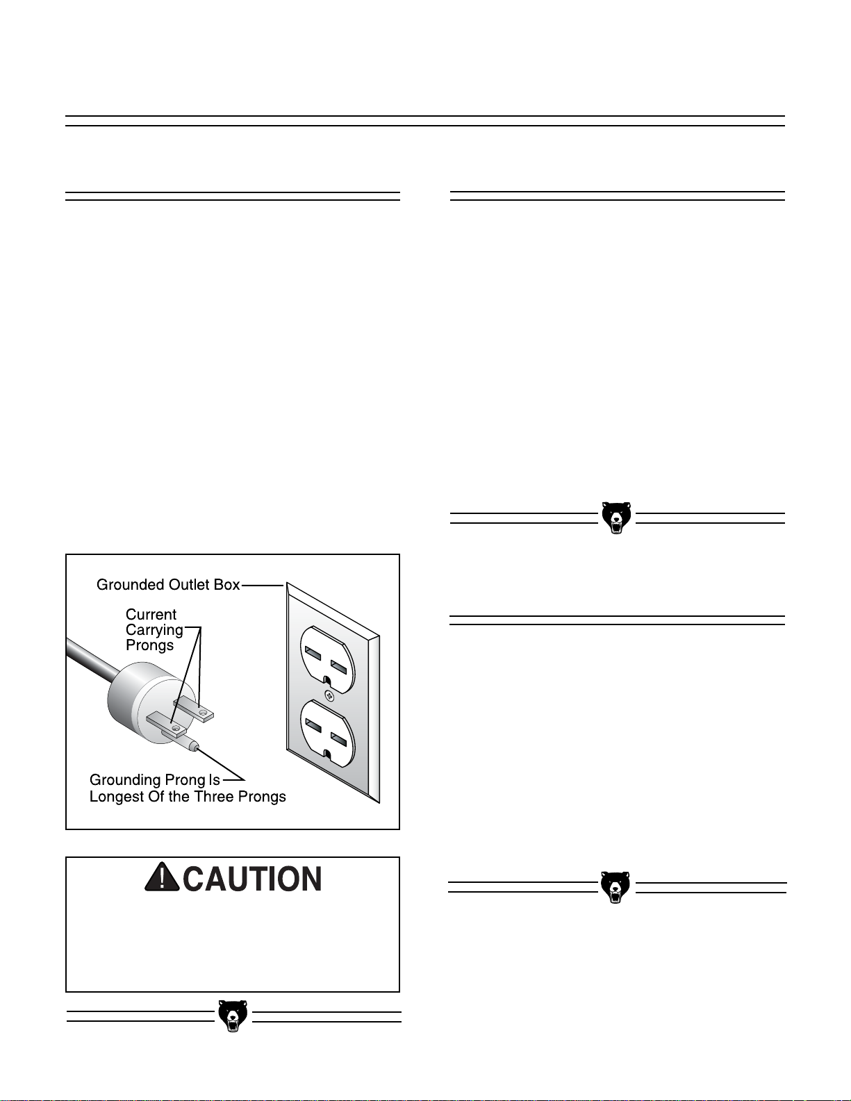
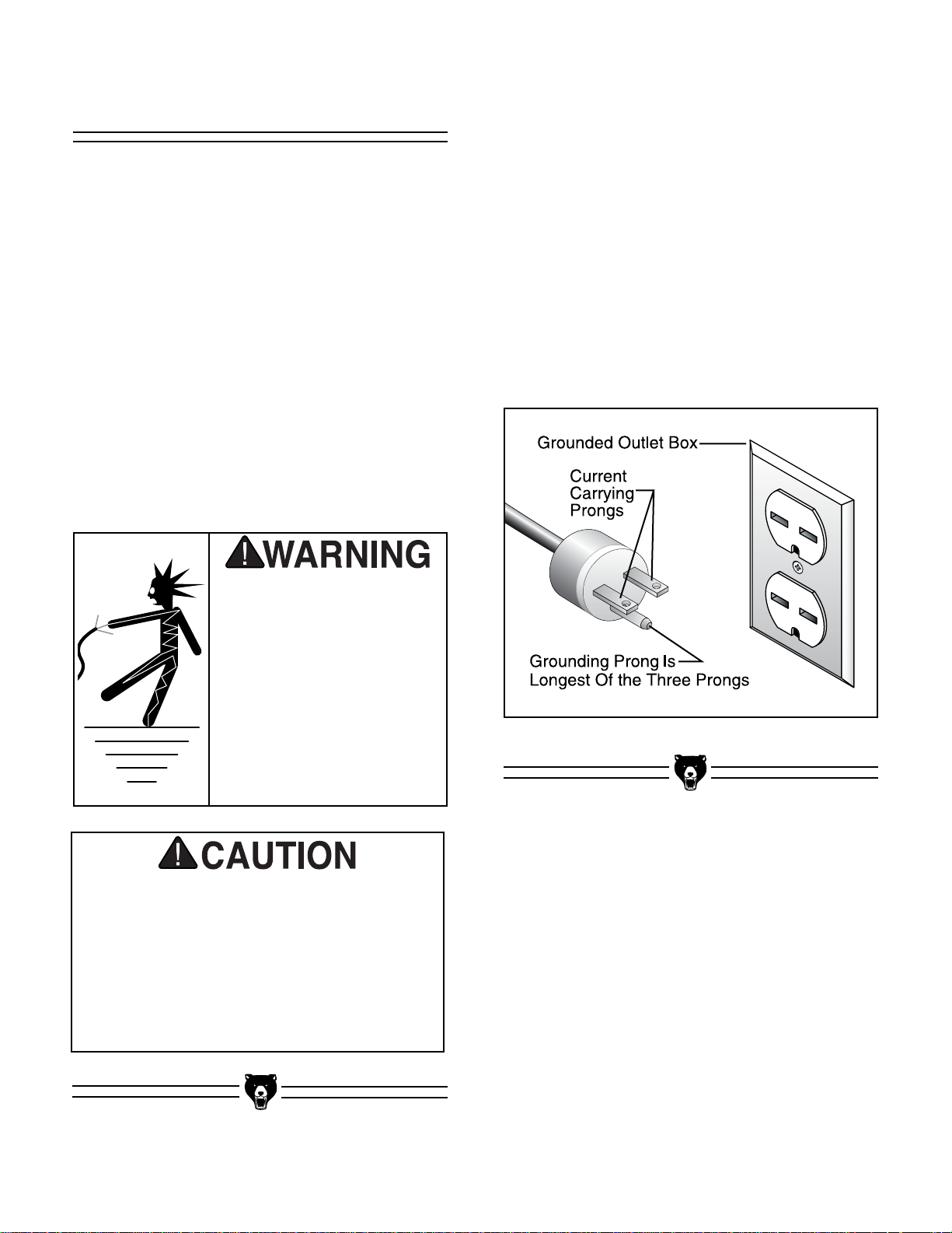
Figure 2.
Under no circumstances should the grounding
pin from any three-pronged plug be removed. If it
will not fit the outlet, have the proper outlet
installed by a qualified electrician.
Check with a qualified electrician or one of our
service personnel if the grounding instructions
are not completely understood, or if you are in
doubt as to whether the tool is properly grounded.
Use only 3-wire extension cords that have 3prong grounding type plugs and 3-hole receptacles that accept the tool’s plug, similar to that in
Figure 2.
Repair or replace damaged or worn cords immediately.
Grounding
In the event of a malfunction or breakdown,
grounding provides a path of least resistance for
electric current to reduce the risk of electric
shock. This tool is equipped with an electric cord
having an equipment grounding conductor. A
plug with a grounding pin must be plugged into a
matching outlet that is properly installed and
grounded in accordance with all local codes and
ordinances.
Improper connections of the electrical-grounding
conductor can result in risk of electric shock. The
conductor with green or green and yellow striped
insulation is the electrical grounding conductor. If
repair or replacement of the electric cord or plug
is necessary, do not connect the equipment
grounding conductor to a live terminal.
We have covered some basic electrical
requirements for the safe operation of your
bandsaw. These requirements are not necessarily comprehensive. You must be sure
that your particular electrical configuration
complies with local and state codes. Ensure
compliance by checking with your local
municipality or a licensed electrician.
This equipment must be
grounded. Verify that any
existing electrical outlet
and circuit you intend to
plug into is actually
grounded. Under no circumstances should the
grounding pin from any
three-pronged plug be
removed. Serious injury
may occur.
Page 9

G1073/G1073Z 16'' Bandsaw -7-
Grizzly Industrial, Inc. is proud to offer the Model
G1073 and G1073Z 16" Bandsaws. These bandsaws are a part of Grizzly’s growing family of fine
woodworking machinery. When used according
to the guidelines stated in this manual, you can
expect years of trouble-free, enjoyable operation,
and proof of Grizzly’s commitment to customer
satisfaction.
The Models G1073 and G1073Z are essentially
the same machine with the exception of the different style stands. Both feature a cast iron, onepiece body, 3 speed pulley system, and a 7
3
⁄4"
cutting height. Also included are a fence, miter
gauge, guards, and
1
⁄2" blade. The saw is
equipped with a 1725 R.P.M., 2 H.P. motor. The
Model G1073 comes with an open stand, and the
Model G1073Z comes with a cabinet stand.
SECTION 3: GENERAL INFORMATION
We are also pleased to provide this manual with
the Model G1073/G1073Z. It was written to guide
you through assembly, review safety considerations, and cover general operating procedures. It
represents our latest effort to produce the best
documentation possible. If you have any comments or criticisms that you feel we should
address in our next printing, please write to us at:
Grizzly Industrial, Inc.
C
⁄O Technical Documentation
P.O. Box 2069
Bellingham, WA 98227
Most important, we stand behind our machines. If
you have any service questions or parts requests,
please call or write us at the location listed below.
Grizzly Industrial, Inc.
1203 Lycoming Mall Circle
Muncy, PA 17756
Phone: (570) 546-9663
Fax: (800) 438-5901
E-Mail: techsupport@grizzly.com
Web Site: http://www.grizzly.com
The specifications, drawings, and photographs
illustrated in this manual represent the Model
G1073/G1073Z as supplied when the manual
was prepared. However, owing to Grizzly’s policy
of continuous improvement, changes may be
made at any time with no obligation on the part of
Grizzly. However, we always keep current Grizzly
manuals available on our website at www.griz
zly.com. Any updates in your machine will be
reflected in these manuals as soon as they are
complete.
Read the manual before
assembly and operation.
Become familiar with
the machine and its
operation before beginning any work. Serious
personal injury may
result if safety or operational information is not
understood or followed.
Page 10

-8- G1073/G1073Z 16" Bandsaw
Piece Inventory
After all the parts have been removed from the
carton, you should have:
• Bandsaw Unit with Blade
• Motor
• Stand Parts (1073)
• Cabinet Stand (1073Z)
• Table Support Bracket
• Miter Gauge
• Table
• Mounting Bracket
• Fence
• V-Belt
• Pulley Guard
• Dust Port
Hardware Qty
Carriage Bolts
5
⁄16"-18 x 5⁄8" 24
(does not apply for G1073Z)
Hex Bolts
1
⁄4"-20 x 3⁄4"2
Hex Bolts
5
⁄16"-18 x 1" 4
Carriage Bolts
5
⁄16"-18 x 1" 4
(does not apply for G1073Z)
Hex Bolts
3
⁄8"-16 x 1" 2
Hex Bolts
3
⁄8"-16 x 2" 4
Hex Nuts
1
⁄4
"-20 2
Hex Nuts
5
⁄16"-18 32
(4 for G1073Z)
Hex Nuts
3
⁄8
"-16 6
(4 for G1073Z)
Flat Washers
5
⁄16"32
(4 for G1073Z)
Anti Vibration Pads 4
Flat Washers
3
⁄8"12
(8 for G1073Z)
Cap Screws
1
⁄4"-20 x 11⁄4"4
Fence Rail Spacers 4
Flat Washers
1
⁄4"4
In the event that any non-proprietary parts are
missing (e.g. nuts or washers), we would be glad
to replace them, or for the sake of expediency,
replacements can be obtained at your local hardware store.
Unpacking
The Model G1073 Bandsaw is shipped from the
manufacturer in a carefully packed carton, and
the Model G1073Z is shipped in two cartons. If
you discover the machine is damaged after you
have signed for delivery, please call Customer
Service immediately for advice.
Save the containers and all packing materials for
possible inspection by the carrier or its agent.
Otherwise filing a freight claim can be difficult.
When you are completely satisfied with the condition of your shipment, you should inventory its
parts.
The Model G1073/G1073Z is a
heavy machine (456 lbs. shipping weight). DO NOT overexert yourself while unpacking or moving your machine –
get assistance.
If moving this machine up
or down stairs, the
machine must be dismantled and moved in smaller
pieces. Make sure the
stairs are capable of supporting the combined
weight of the machine
parts and the people moving them.
Some metal parts may
have sharp edges on them
after they are formed.
Please examine the edges
of all metal parts before
handling them. Failure to
do so could result in
injury.
Page 11

G1073/G1073Z 16'' Bandsaw -9-
Clean up Site Considerations
1. Floor Load: Your Model G1073/G1073Z 16''
Bandsaw represents a large weight load in a
small footprint. Most commercial floors are
suitable for the Model G1073/G1073Z. Some
residential floors may require additional build
up to support both machine and operator.
2. Working Clearances: Consider existing and
anticipated needs, size of material to be
processed through each machine, and
space for auxiliary stands, work tables or
other machinery when establishing a location for your bandsaw.
3. Lighting and Outlets: Lighting should be
bright enough to eliminate shadow and prevent eye strain. Electrical circuits should be
dedicated or large enough to handle amperage requirements. Outlets should be located
near each machine so power or extension
cords are clear of high-traffic areas. Observe
local electrical codes for proper installation
of new lighting, outlets, or circuits.
The unpainted surfaces are coated with a waxy
oil to protect them from corrosion during shipment. Remove this protective coating with a solvent cleaner or citrus-based degreaser such as
Grizzly’s G7895 Degreaser. Avoid chlorinebased solvents as they may damage painted
surfaces should they come in contact. Always
follow the usage instructions on the product you
choose for clean up.
Do not use gasoline or
other petroleum-based
solvents to clean with.
They have a low flash
point which makes them
extremely flammable. A
risk of explosion and
burning exists if these
products are used.
Serious personal injury
may occur.
Make your shop “child safe.”
Ensure that your workplace
is inaccessible to children
by closing and locking all
entrances when you are
away. Never allow visitors in
your shop when assembling,
adjusting, or operating
equipment.
Do not smoke while using
solvents. A risk of explosion or fire exists and may
result in serious personal
injury.
Many of the solvents
commonly used to clean
machinery can be toxic
when inhaled or ingested. Always work in wellventilated areas far from
potential ignition sources
when dealing with solvents. Use care when disposing of waste rags and
towels to be sure they do
not create fire or environmental hazards.
Page 12

-10- G1073/G1073Z 16" Bandsaw
SECTION 4: ASSEMBLY
Figure 3. Attaching motor mount bracket.
Figure 4. Motor attached to motor mount bracket.
Stand (G1073)
The stand assembly on the Model G1073 is
shown here. If you have the Model G1073Z, follow the same instructions for mounting the motor,
bandsaw to stand, and the anti-vibration pads.
Disregard the steps that do not apply.
To ease assembly, build the stand upside down
on a bench, then place it upright on the floor. Do
not fully tighten any of the bolts until directed to
do so in the next section.
Sometimes sheet metal parts have a tendency to
''spring'' after they are formed. For this reason,
you may need to use a little extra force to align
holes to insert bolts.
2. Position the motor so the pulley is over the
rectangular hole in the stand top as shown in
Figure 4. Secure with four (4)
5
⁄16"-18 x 1"
carriage bolts,
5
⁄16" washers, and 5⁄16"-18 nuts
provided.
To assemble the stand:
1. Flip the top of the stand upside-down.
Position the motor mounting bracket so that
it sits over the four (4) evenly spaced holes
in the top. Bolt the bracket to the stand with
two (2)
3
⁄8"-16 x 1" hex bolts, 3⁄8" washers,
and
3
⁄8"-16 nuts provided. Hand tighten for
now so your assembly looks like Figure 3.
Keep loose clothing
rolled up and out of the
way of machinery and
keep hair pulled back.
Wear safety glasses during the entire assembly
process. Failure to comply may result in serious
personal injury.
Disconnect power to the
machine when performing any maintenance or
assembly. Failure to do
this may result in serious
personal injury.
Page 13
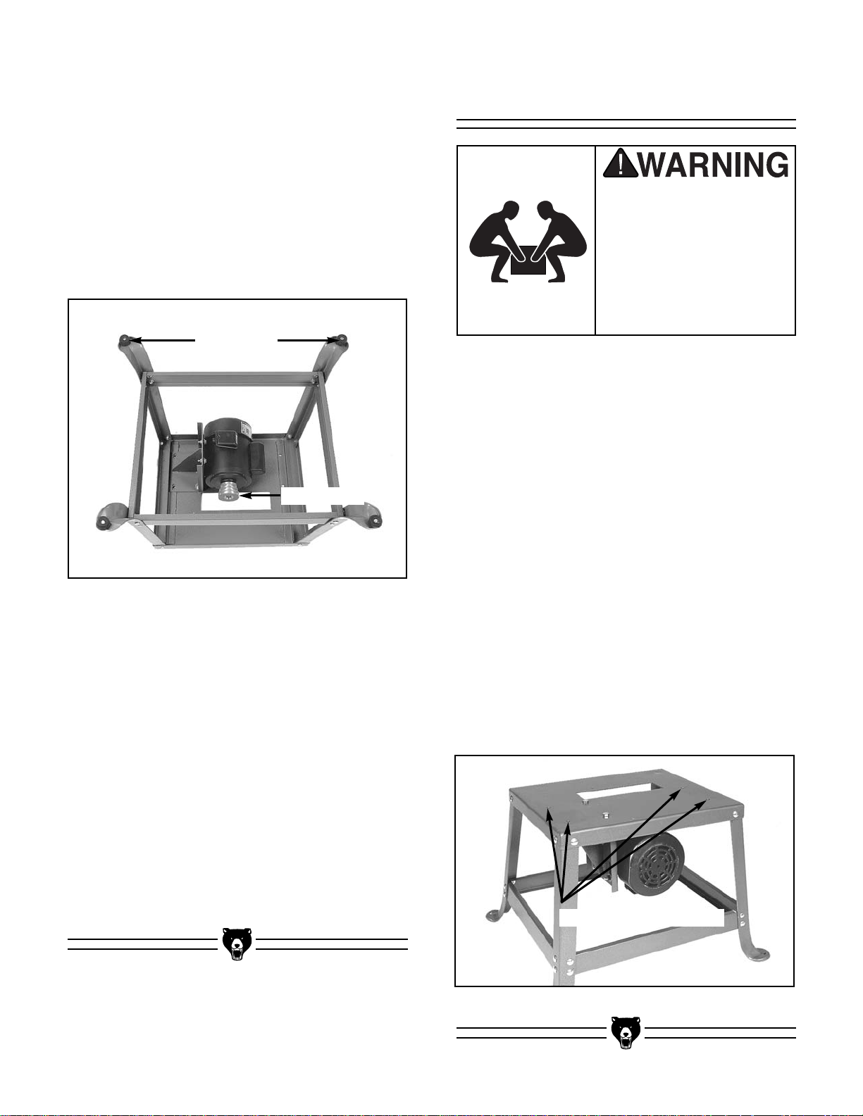
G1073/G1073Z 16'' Bandsaw -11-
Figure 5. Legs and braces attached to top.
3. Attach the four (4) legs to the inside of the
stand top and the four horizontal braces to
the inside of the legs as shown in Figure 5.
Use the
5
⁄16"-18 x 5⁄8" carriage bolts, 5⁄16"-18
nuts, and
5
⁄16" washers provided. The two
shorter braces are slightly wider than the
longer braces. When attaching the braces to
the legs, the longer braces rest inside the
two flanges of the shorter braces. The
square holes in the legs are angled to
accommodate the angle of the legs.
4. Attach the four (4) rubber feet to the legs.
Use four (4)
5
⁄16"-18 x 1" hex head bolts, four
(4)
5
⁄16" flat washers and four (4) 5⁄16"-18 nuts
provided. The bolts should go through the
pad first and then through the feet. Tighten
carefully so you do not deform the rubber
feet.
5. Slide the motor pulley onto the motor shaft
and tighten the setscrew down. The small
end of the pulley should be near the motor.
6. Flip the stand/motor assembly rightside-up
on the floor, but do not tighten the stand
hardware at this time.
Rubber Feet
Motor Pulley
Figure 6.
Bandsaw Mounting Holes
Bandsaw To Stand
1. Safely lift the bandsaw onto the stand.
Ensure that the bandsaw step pulley is positioned over the hole in the stand.
2. Attach the bandsaw to the stand with four (4)
3
⁄8"-16 x 2" hex bolts, four (4) 3⁄8"-16 hex nuts,
and eight (8)
3
⁄8" washers provided. The bolts
on the left side should go through the motor
mount bracket. Hand tighten for now.
3. Position the bandsaw on the stand so that
the legs are evenly balanced and the stand
is symmetrical in appearance, rather than
lopsided. When the stand is positioned correctly on all four sides, tighten all the stand
nuts to secure it in place.
4. Working from the bottom up, tighten all stand
bolts, motor mount bracket to the stand top
(leave the motor bolts loose for now), and
the bandsaw mounting bolts at the holes
shown in Figure 6.
The bandsaw (without stand
and motor) weighs approximately 325 lbs. Use a lifting
device or get help from people who can safely lift that
much weight. Serious personal injury may occur if
this warning is ignored.
Page 14

-12- G1073/G1073Z 16" Bandsaw
Figure 8. Pulley speed chart diagram.
V-Belt
To ensure optimum power transmission from the
motor to the band wheels, align the pulleys, and
tighten the V-belt.
To install the V-belt:
Slip the V-belt over the motor pulley and step pulley. Position the V-belt on the pulleys according
to the speed you want (see Figure 8 for speed
chart). For general woodworking, we recommend
the fastest blade speed.
Figure 7. Plugging cords together.
Wiring The Motor
1. The Model G1073/G1073Z motor and
ON/OFF switch each have a special connector for ease of wiring. Plug the connectors
into each other as illustrated in Figure 7.
2. The motor is prewired for 220 volt operation.
Install the appropriate 220V plug onto the
power cord.
3. If 110 volt operation is desired and you are
inexperienced with wiring, contact our
Service Department for further information.
4. A wiring diagram is located on Page 31 of
this manual to further assist you with wiring
details.
Page 15

G1073/G1073Z 16'' Bandsaw -13-
Figure 10. Aligning V-belt pulleys.
Pulley alignment and belt tension should now
be adjusted simultaneously.
1. Situate the motor so the V-grooves on the
motor pulley approximately line up with the
V-grooves on the three-step pulley. You may
need to loosen the motor mount bracket
bolts shown in Figure 9A to position the
motor properly. Tighten the mount bracket to
the stand before moving on to the next step.
Leave the motor mount bolts loose.
Figure 9B. Pulley deflection w/moderate pressure.
Figure 9A. Motor mount bolt locations.
If the pulleys will not align by moving the
motor only, loosen the bandsaw mounting
bolts and position the bandsaw so the step
pulley aligns with the motor pulley. Leave the
motor mount bolts loose.
2. Slide the motor up or down to achieve prop-
er V-belt tension. You should be able to
deflect the V-belt about
3
⁄4" at its midpoint
(see Figure 9B) using moderate finger pressure. Be careful not to change the lateral
position of the motor and move the pulleys
out of alignment. Tighten the motor mount
bolts.
Plumb bob
Motor Mount
Bolts
3. Check the pulley alignment with a plumb bob
or straightedge. If you are using a plumb
bob, the string must touch the outside
flanges of each pulley evenly as shown in
Figure 10, and the machine must be level.
4. Check V-belt tension. Repeat steps 1-4 until
both tension and pulley alignment are correct.
Page 16

-14- G1073/G1073Z 16" Bandsaw
Figure 11. Trunnions removed from bandsaw.
Figure 12. Under table controls.
7. Place the table insert in the table top and
slide the table pin so it fits snugly in the hole
on the right side of the table. DO NOT use
excessive force.
2. Place the trunnion support on the body cast-
ing over the mounting holes, and secure it
with the three bolts you just removed, making sure the support is placed so that the
blade is centered between the guide-block
brackets.
3. Release tension and remove blade. Refer to
“Blade Changes” instructions if you need
help. Position the table so that the miter slot
will be to the right of the blade as you face
the front of the bandsaw.
4. Orient the trunnion bolts under the table so
they hang vertically.
5. Set the table trunnions onto the support.
Make sure the trunnion bolts drop through
the trunnion support slots.
6. Secure the table to the trunnion supports by
tightening the two star knobs onto the trun-
nion bolts shown in Figure 12.
Working Table
The table secures to the trunnion support which
mounts to the body casting. The trunnions are
premounted to the table.
To mount the table and trunnion support:
1. Remove the three table bracket mounting
bolts from the bandsaw body. Figure 11
shows them removed.
Star Knobs
Trunnion
Table Pin
Trunnion
Trunnion
Support
Trunnion Support Mounting Holes
NOTICE
The tapered table pin must be in position
when operating the bandsaw.
Page 17

G1073/G1073Z 16'' Bandsaw -15-
Figure 13. Fence rails properly secured to table.
Figure 14. Fence mounted on rails.
2. Screw the fence locking handle into its posi-
tion on the cam on the fence headstock.
Move it to the loose (up) position.
3. Slide the fence onto the fence rails as shown
in Figure 14.
Fence
The mounting holes in the rails are not centered
on the length of the rails. This way, you can
mount the rails so that maximum fence travel will
be greater on one side or the other.
To mount the rails:
1. Secure the fence rails to the table with the
four (4)
1
⁄4"-20 x 11⁄4" cap screws and spacers
provided (Figure 13).
Rail Spacers
There are two ways to remove the fence:
1. Remove the blade so the fence slides off
the rails.
2. Dismount the rails by removing the cap
screws.
NOTICE
When the fence is to the left of the blade,
the fence must be positioned near the center of the table in order to open the lower
wheel cover.
Page 18

-16- G1073/G1073Z 16" Bandsaw
Figure 15. Belt guard and dust port mounted
correctly on bandsaw.
Guard
Place the belt guard over the step pulley and
secure it, as shown in Figure 15, to the stand
using the
1
⁄4"-20 x 1⁄2" hex head bolts, washers,
and nuts provided. Fasten the guard to the bandsaw by inserting the threaded rod through to the
body casting and tightening the knob.
Dust Port
The Model G1073 comes standard with a 21⁄2"
dust port for dust collection. It mounts to the lower
rear casting body. This port can be connected
directly to a 2
1
⁄2" Shop•Vac®hose or adapted to fit
a standard 4" dust collector hose by using the
Grizzly Model G3119 adapter between a 2
1
⁄2" and
4" hose.
To mount the dust port:
1. Remove the four dust port mounting screws
from the bandsaw body and position the dust
port as shown in Figure 15.
2. Replace the screws and secure the dust port
to the bandsaw body.
Dust Port
Belt Guard
Page 19

G1073/G1073Z 16'' Bandsaw -17-
Blade Tension
Blade Tracking
SECTION 5: ADJUSTMENTS
To adjust the tension:
1. Loosen the upper and lower guide blocks
and lower the upper guide block down to the
table. With moderate tension already on the
blade, turn the bandsaw ON.
2. Release the tension one quarter of a turn at
a time. Do this very slowly. When you see
the bandsaw blade start to flutter, stop
decreasing the tension.
3. Now, slowly increase the tension until the
blade stops fluttering. Tighten the tension
one quarter of a turn.
There are two ways to track a bandsaw blade:
Center Tracking and Coplanar Tracking.
Center Tracking is the fastest and easiest, but not
the most precise.
Center Tracking:
1. Disconnect the bandsaw from the power
source and adjust the upper and lower guide
assemblies away from the blade. Refer to
Page 18 for adjustment details.
2. Loosen the lock collar on the tracking control
knob shown in Figure 17. Turn the tracking
control knob clockwise/counterclockwise
while turning the upper wheel by hand until
the blade stays centered on the rubber tire.
Keep loose clothing
rolled up and out of the
way of machinery and
keep hair pulled back.
Wear safety glasses during the entire adjustments process. Failure
to comply may result in
serious personal injury.
Disconnect power to the
machine when performing any maintenance or
assembly. Failure to do
this may result in serious
personal injury.
If the tension seems correct, turn the bandsaw
OFF and make the other adjustments, and test
run. If the blade does not cut properly, the tension
may be incorrect. Readjust the tension. New
blades often stretch with use. However, it helps to
always remove the tension from the blade when
not in use.
Figure 17. Tracking and tension controls.
Tracking Knob
Lock Collar
Tension Knob
NOTICE
Read through the entire manual before
starting the table saw.
Page 20

-18- G1073/G1073Z 16" Bandsaw
Blade Guides
You must check the upper and lower support
bearings and guide blocks each time before starting your bandsaw.
Always adjust the assemblies away from the
blade before installing a new blade or making
blade tracking adjustments. After blade tension
and tracking are set correctly, readjust the upper
and lower support bearings and guide block
assemblies into position. See Figure 18A control
locations.
Figure 18A. Upper guide assembly.
Figure 18B. Eccentric blade support.
Adjustment
Knobs
The support bearings back-up the blade during
the sawing operation. To adjust the support
bearings:
1. Loosen guide blocks and loosen the
setscrew that holds the guide block assembly to the guide post. Remove the guide
block assembly.
2. Loosen the thumbscrew that secures the
support bearing shaft and unscrew the
adjustment knob that controls the support
bearing shaft. See Figures 18A/B for loca-
tions.
3. Remove the support bearing shaft from the
guide block assembly. Rotate the the shaft
so the blade will ride off-center against the
support bearing as shown in Figure 18B.
Install the shaft, tighten the mounting
setscrew and replace the adjustment cap.
4. Turn the adjustment cap so that the upper
and lower support bearings are approximately .016" (thickness of a dollar bill x 4)
behind the blade. Tighten the thumbscrews.
5. To adjust the lower support bearing, remove
the lower guide block assembly by taking out
the two setscrews that mount it to the bandsaw body. Make the same adjustments
described in steps 2-4 and mount the guide
block assembly back to the bandsaw body.
Support Bearing
Support Bearing
Shaft
Guide Block
Eccentric Shaft
Support Bearing
Always disconnect
power to the machine
when making adjustments. Failure to do this
may result in serious
personal injury.
3. Tighten the lock collar and check the track-
ing.
For the best performance from your saw, regularly maintain proper tracking of the blade.
For Coplanar Tracking, see the “Wheel
Alignment” instructions.
Page 21

G1073/G1073Z 16'' Bandsaw -19-
Figure 20. Squaring table to blade.
Table Stop
1. Loosen the star knobs under the table and
the checknut securing the stop.
2. Raise the upper blade guide assembly and
place a 6" machinist’s square on the table
against the blade as shown in Figure 20.
Notice how far out of square your table is
and approximate this distance by adjusting
the positive stop up or down. Turning the
positive stop counterclockwise will raise it
and turning clockwise will lower it. Adjust the
positive stop so the table will stop at a 90°
angle (square) to the blade.
3. Lock the positive stop by tightening the
checknut. Do not let the stop turn while tightening the checknut. Tighten the star knobs.
Set the angle pointer to zero on the gauge.
Figure 19. Guide block location of controls.
Guide Blocks
The guide blocks ensure that the blade is not
pushed too far laterally. Perform steps 1-4 for
both upper and lower guide blocks. To adjust the
guide blocks:
1. Loosen the thumbscrew securing the guide
block shaft shown in Figure 19.
2. Turn the adjustment nut so that the front of
the guide blocks are just behind the gullet
line (the hollow points) of the blade. Tighten
the thumbscrew.
3. Loosen the guide block thumbscrews and
adjust the gap between the blocks and the
blade to .004" (about the same thickness as
a dollar bill). See Figure 19.
4. Tighten the thumbscrews.
4. A stop cap covers the positive stop. A pre-
determined thickness in the end of this cap
will automatically allow the table to tilt toward
the column of the saw 10
°
when this cap is
removed as shown Figure 21.
Always disconnect
power to the machine
when making adjustments. Failure to do this
may result in serious
personal injury.
The positive stop under the table allows you to
repeatedly square up the table after adjusting the
table tilt.
To adjust this positive stop so the table will
return perpendicular (90°) to the blade after
angle cutting:
Page 22

-20- G1073/G1073Z 16" Bandsaw
Table Tilt
To tilt the table:
1. Loosen the two star knobs below the trun-
nions shown in Figure 22.
2. Tilt the table to the desired angle. Refer to
the angle gauge.
3. Tighten the star knobs.
Table Parallelism
To position the blade line parallel to the miter
slot:
1. Ensure that the bandsaw is not connected to
a power source, and install the widest blade
available.
2. Loosen the 6 bolts securing the trunnions to
the table OR loosen the 3 trunnion support
mounting bolts securing the trunnion support
to the bandsaw. Leave the star knobs tight.
Figure 22 shows the location for these con-
trols.
3. Lay a straightedge against the left side of the
blade so that the straightedge touches the
front and back side of the blade.
4. With a fine ruler, measure the distance from
the straightedge to the edge of the miter slot.
This measurement should be taken at both
the front and back of the table. If both mea-
surements are the same, proceed to step 6.
5. Rotate the table in the desired direction until
the two measurements at the front and back
are even.
Figure 22.
Star Knobs
Trunnion Mount Bolts
Figure 21.
Stop Cap
6. Secure the table by tightening the bolts.
Make sure the table did not shift. If you continue to have problems with this, see the
“Blade Lead” instructions.
NOTICE
If setting table tilt to the left, first tilt the table to
the right, remove the cap on the positive stop,
and then tilt the table to the left.
Page 23

G1073/G1073Z 16'' Bandsaw -21-
Figure 23. Changing blade with leather gloves.
Blade Changes
To remove the blade:
1. Release tension on the blade by turning the
tension control knob counterclockwise.
2. Remove the table insert and table pin.
3. Adjust upper and lower guide blocks away
from the blade.
4. Put on leather gloves to protect your hands
from the sharp teeth of the blade.
5. Open the upper and lower wheel covers and
slide the blade off both wheels. Use cautionthe blades are sharp!
6. Rotate the blade 90° so it will slide through
the slot in the table as shown in Figure 23.
When removing or installing wide blades, it may
be convenient to completely remove the upper
and lower guide blocks. Be sure to replace them
before cutting. To replace the blade:
1. Slide the blade through the table slot, ensur-
ing that the teeth are pointing down toward
the table.
If the teeth will not point downward in any orientation, the blade is inside out. Put on
heavy gloves, remove the blade, and twist it
inside out.
Wear gloves and safety goggles when handling blades. Coiled blades spring open as
they are uncoiled and could cause deep
cuts or lacerations.
2. Slip the blade through the upper and lower
guides, and mount it over the upper and
lower wheels.
3. Apply tension, then check and adjust track-
ing.
4. Adjust the upper and lower guide blocks and
support bearings.
5. Close the wheel covers and latch them.
6. Replace the table insert and table pin, being
sure not to use excessive force.
Always disconnect
power to the machine
when changing blades.
Failure to do this may
result in serious personal injury.
Page 24

-22- G1073/G1073Z 16" Bandsaw
Bracket Bolts
Figure 25A. Location of bracket bolts.
To adjust the guide post bracket:
1. Loosen the two bracket bolts (shown in
Figure 25A) securing the guide post bracket
to the body casting.
2. Shift the guide post bracket in the desired
direction to center the blade between the
blade guide bracket.
3. Tighten the two hex bolts and check your
results by sliding the guide post up and
down. If the post is correct, the blade will
remain centered in the blade guide brackets.
4. Repeat Steps 1-3 as needed.
If the guide post bracket will not adjust enough,
shift the blade slightly.
Setscrew
Figure 24B. Eccentric at bottom of guide post.
Eccentric
Guide Post
4. Note where the blade is in the guide block
holder. It should be roughly centered. If it is
not centered, shift the eccentric at the bot-
tom of the guide post (shown in Figure 24B).
This is done by loosening the setscrew on
the guide block assembly and pulling it off
the guide post. The setscrew on the back of
the guide post will allow you to loosen the
eccentric so you can center the assembly to
the blade.
5. Slide the guide post all the way down and
lock it in position. If the blade appears to be
closer to one side of the guide block holder
than when the guide post was all the way up,
adjust the guide post bracket.
Guide Post
The guide post is adjustable so the guide blocks
will stay aligned with the blade when the guide
post is raised or lowered.
To check guide post alignment:
1. Adjust blade tension and tracking.
2. Loosen the guide post securing knob and
slide the guide post all the way up. Lock it in
position by tightening the securing knob
shown in Figure 24A.
3. Adjust the upper guide blocks away from the
blade.
Guide Post Securing Knob
Blade Tension Control Knob
Figure 24A. Tension and guide post controls.
Page 25

G1073/G1073Z 16'' Bandsaw -23-
Figure 26. Location of checknut.
Fence Adjustment
Use a tape measure or ruler to measure the dis-
tance from the fence to the blade. To adjust the
front clamping pressure:
1. Lift the lever to the “loose” position.
2. Loosen the checknut below the clamp shoe
shown in Figure 26.
Checknut
Clamp Shoe Hex Bolt
To shift the blade:
1. Loosen the tension on the blade.
2. Remove the spacers (See Figure 25B)
behind the upper wheel in the desired direction. Move the upper wheel left or right as
needed, and replace the spacers on the
opposite side from where they were
removed.
3. Readjust the tension. This will secure the
wheel.
4. Repeat guide post bracket adjustments.
Figure 25B. Upper wheel spacer.
Fence locking is controlled by the lever on the
front of the fence. When the lever is pushed
down, it locks the front and rear of the fence to
the guide rails. The end of the fence nearest to
the operator should lock before the rear.
3. Using a wrench, turn the clamp shoe hex bolt
to adjust the clamping pressure.
4. Push the locking lever down to test the
clamping pressure. The fence should be
tightly clamped to the front rail when the
lever is pushed all the way down.
5. Repeat steps 3-4 until the fence clamps cor-
rectly. Tighten the checknut. Be careful not
to turn the clamp shoe hex bolt or the clamping pressure will be altered.
To adjust the rear clamping pressure:
1. Back out the rear clamp adjusting screw sev-
eral turns and put the locking lever in the
locked position as shown in Figure 27.
2. Turn the rear clamp adjusting screw until the
rear clamp just touches the top of the rear
guide rail.
3. Continue to turn the rear clamp adjusting
screw another
3
/4 turn.
4. Test the clamping pressure by loosening and
tightening the locking lever.
Page 26

-24- G1073/G1073Z 16" Bandsaw
Figure 28. Blade leading away from line of cut.
Blade Lead
Most bandsaw blades will not appear to cut
straight when using the fence or miter gauge.
This is called “lead.” (See Figure 28.) Lead
occurs (1) if the blade tension is incorrect, (2) if
the teeth are dull on one side, or (3) if the teeth
are set heavier on one side of the blade than the
other.
If you notice that your blade is not cutting
straight (i.e. leading) while using the fence or
miter gauge:
1. Check that the miter slot is parallel to the
blade line.
2. Check that you have proper blade tension. If
the blade tension is correct and it is not convenient to replace the blade, compensate for
lead by skewing the fence or adjusting the
table.
To skew your fence:
1. Make a piece of scrap wood that is approxi-
mately
3
⁄4" thick x 3" wide x 17" long. On a
wide face of the board, draw a straight line
parallel to the long edge.
2. Slide the fence out of the way and cut free-
hand along the line. Stop at the halfway
point. Turn the bandsaw off and wait for the
blade to stop.
3. Clamp the board to the bandsaw table without moving it. Now slide the fence over to
the board so it barely touches one end of the
board.
4. Loosen the two skewing cap screws on top
of the fence. Figure 27.
5. Skew the fence left or right so it is parallel to
the edge of the scrap piece. You may need
to readjust the fence locking mechanisms to
gain maximum adjustment.
6. While maintaining the skew, tighten the cap
screws.
Figure 27. Fence controls.
Rear Clamp
Adjusting Screw
Skewing Cap Screws
Rear Clamp
5. Slide the fence along the rails. It should slide
easily.
6. Lock the handle again and check fence posi-
tion. The front of the fence should lock just
before the rear of the fence as the handle is
pushed down through its full motion.
Page 27

G1073/G1073Z 16'' Bandsaw -25-
Figure 29. Holding a straightedge across both wheels.
Wheel Alignment
Wheel alignment is one of the easiest ways to
ensure you get optimal performance from your
bandsaw. When wheels are aligned, or coplanar,
the bandsaw is more likely to cut straight without
wandering; and vibration, heat, and blade wear
are considerably decreased because the blade is
automatically balanced on the wheel. This is
known as “Coplanar Tracking.”
To verify if the the upper and lower wheels are
coplanar:
1. With the blade on and properly tensioned,
hold a straightedge close to the center of
both wheels. Make sure it fully extends
across them as in Figure 29.
To compensate for lead if making straight
crosscuts using the miter gauge, you will
need to shift the table. To do this:
1. On a scrap piece of wood, mark a line that is
perpendicular to the front edge. Starting
where the line begins, cut the board by pushing it through the blade with the miter gauge.
2. Loosen the table mounting bolts according to
the instructions about “Table Parallelism” on
page 20. Shift the table to compensate for
the blade lead.
3. Repeat steps 1 and 2 until the blade cuts
straight when wood is pushed through with
the miter gauge.
NOTICE
Lead adjustments will change when new
blades are mounted in the saw.
NOTICE
If the table is shifted, the fence will be affected since it is attached.
2. A perfectly coplanar set of wheels will allow
the straightedge to touch the top and bottom
of the outside rims on each wheel. If this is
the case with your wheels, then they are
coplanar.
3. If your wheels are not coplanar, check them
for adjustment by placing the straightedge
on the upper wheel first – ensuring that it
touches both the top and bottom rim – and
adjust the tracking knob to see how the
straightedge lines up with the lower wheel.
If the straightedge only touches the top rim of
the lower wheel, then the upper wheel needs
to be shimmed.
If the straightedge only touches the bottom
rim of the lower wheel, then the lower wheel
needs to be shimmed.
Shimming a wheel.
1. Adjust the tracking knob so the top wheel is
parallel with the bottom wheel. With the
straightedge touching both points of the
wheel that does not need to be adjusted,
measure the distance away from the incor-
rect wheel with a fine ruler. See Figure 30.
The distance you measured with the ruler is
the distance the wheel must be corrected.
Page 28

-26- G1073/G1073Z 16" Bandsaw
Figure 32. Horizontal controls for upper wheel.
2. Adjust the setscrews in or out very slightly
(over-adjustment will cause the tension rod
to bind). Use your straightedge from the previous section to make the upper wheel parallel with the lower wheel.
3. Tighten the four cap screws and check wheel
alignment.
1. Loosen the four cap screws securing the two
sliding gibs to the body behind the upper
wheel, as shown in Figure 32.
Cap Screw
Setscrew
Figure 31. Coplanar diagram.
Adjusting Parallelism
To adjust a parallelism problem (i.e., if the middle
of the wheels are coplanar, but the sides are not,
Figure 31.) follow these steps.
Sliding Gib
Figure 30. Measuring wheel difference.
3. Replace wheel, any remaining washers and
the securing nut. It is important to tighten the
blade as it will be used during operation
before you check the wheels for being
coplanar. In other words, it is possible that
the wheels may be coplanar with the blade
loose, then be pulled out of alignment when
it is tightened.
4. The first time you get the wheels coplanar it
is a good idea to place a mark on each
wheel where you held the straightedge. This
assures repeated accuracy every time you
adjust your wheels.
2. Remove the blade from the saw, then the
securing nut and washers from the wheel
that needs to be shimmed. Now remove the
wheel. Use the washers that were behind
the securing nut for shims. Measure how
many you will need to equal the space of
your gap and place them on the mounting
shaft.
NOTICE
When wheels are properly coplanar, the blade
may not be centered on the crown of the wheel,
but it will be balanced.
Page 29

G1073/G1073Z 16'' Bandsaw -27-
Once the assembly is complete and the adjustments are done to your satisfaction, you are
ready to test the machine.
Turn on the power supply at the main panel. Pull
the paddle switch up to start the bandsaw. Make
sure that your hand is poised over the switch in
case there is a problem. The bandsaw should run
smoothly with little or no vibration or rubbing noises. Strange or unnatural noises should be investigated and corrected before operating the
machine further.
If you cannot easily locate the source of an
unusual noise or vibration, feel free to contact our
service department for help.
Test Run
Blade Selections
The Model G1073/G1073Z 16" Bandsaw accepts
113" blades. The tension adjustment will accommodate blades up to a maximum length of 114"
and down to a minimum length of 112" (approx.).
A bandsaw blade is a delicate piece of steel that
is subjected to tremendous strain. Take care of
your blades and they will last a long time. Be sure
you use quality blades of the proper width for the
various types of cutting operations.
Always use the widest blade possible for the
workpiece you are cutting. Use narrow blades
only for sawing small, abrupt curves and for fine,
delicate work. Grizzly supplies bandsaw blades in
various widths for this saw. Please refer to our
current catalog for prices and ordering information.
Many conditions may cause a bandsaw blade to
break. Blade breakage is, in some cases,
unavoidable because of the peculiar stresses to
which bandsaw blades are subjected. Blade
breakage is also due to avoidable causes.
Avoidable breakage is most often the result of
poor care or judgement on the part of the operator when mounting or adjusting the blade or sup-
port guides.The most common causes of blade
breakage are:
• Forcing or twisting a wide blade around a
curve of short radius.
• Feeding material too fast.
• A dull or defective blade.
• Excessive tension.
• Improperly adjusted blade guides.
• Continuously running the bandsaw when not
in use.
SECTION 6: OPERATIONS
Keep loose clothing
rolled up and out of the
way of machinery and
keep hair pulled back.
Wear safety glasses during the entire operation
process. Failure to comply may result in serious
personal injury.
Disconnect power to the
machine when performing any maintenance or
assembly. Failure to do
this may result in serious
personal injury.
Page 30

-28- G1073/G1073Z 16" Bandsaw
Cutting Curves
When cutting curves, simultaneously feed and
turn the stock carefully so that the blade follows
the layout line without being twisted. If a curve is
so abrupt that it is necessary to repeatedly back
up and cut a new kerf, use either a narrower
blade or a blade with more set. A blade with more
set can cut relatively tighter radii, though the cut
is usually rougher than cuts produced by a blade
with medium set.
Always make short cuts first, then proceed to the
longer cuts. Relief cuts will also reduce the
chance that the blade will be pinched or twisted.
Relief cuts are made through the waste portion of
the workpiece and are stopped at the layout line.
As you cut along the layout line, waste wood is
released from the workpiece, alleviating any
pressure on the back of the blade. Relief cuts
also make backing the workpiece out easier, if
needed.
The table below lists blade widths and corresponding minimum radii each blade will cut:
Width Radius
1
⁄8''................................3⁄16''
3
⁄16'' ..............................5⁄16''
1
⁄4''................................5⁄8''
3
⁄8''................................11⁄2''
1
⁄2''................................21⁄2''
5
⁄8''................................4''
3
⁄4''................................51⁄2''
Resawing
Resawing is the process of cutting a board into
two or more thinner boards. The maximum board
width that can be resawn is limited by the maximum cutting height of the bandsaw. Maximum
cutting height for this bandsaw is 7
3
⁄4''.
Use common sense when resawing. Attempting
to resaw too wide or too dense of a board may
put excessive strain on the blade and be dangerous.
Blade selection is an important consideration
when resawing. Generally, the wider the blade,
the better. In most applications, a hook or skip
tooth style will be sufficient. Also, since most
resawn lumber will be planed smooth, you can
choose blades with fewer teeth per inch (from 3
to 6). While blades with fewer teeth per inch produce rougher cuts, these types of blades offer
larger gullet capacities for clearing sawdust, less
heat buildup, and yield more horsepower per
tooth.
To resaw lumber:
1. The bandsaw must be adjusted correctly.
See Blade Adjustment section.
2. The table must be square to the blade. See
Table Adjustment section.
3. Use the widest blade available. The blade
must also be in good condition.
4. Use a fence to guide work.
5. Draw a reference line on the edge of the
board.
6. Support ends of the board if necessary.
7. Feed work slowly and evenly.
Using this machine produces sawdust which may
cause allergic reactions
and respiratory problems.
Use an approved dust
mask to protect yourself
from these hazards!
Page 31

G1073/G1073Z 16'' Bandsaw -29-
SECTION 7: MAINTENANCE
V-Belts
To ensure optimum power transmission from the
motor to the blade, the V-belt must be in good
condition and operate under proper tension. The
belts should be checked for cracks, fraying and
wear. Belt tension should be checked at least
every 3 months; more often if the bandsaw is
used daily.
The V-belt is accessed via the bottom cover:
1. Squeeze the center of the V-belt.
2. Note the amount of deflection. Deflection
should be approximately
3
⁄4". See “V-Belt
Adjustment” instructions.
The table and other non-painted surfaces on the
Model G1073/G1073Z should be protected
against rust and pitting. Wiping the saw clean
after every use ensures that wood dust is not
allowed to trap moisture against bare metal surfaces.
The table can be kept rust-free with regular applications of products like SLIPIT
®
or Boeshield® T-
9. For long term storage you may want to consid-
er products like Kleen Bore's Rust Guardit™. See
the current Grizzly catalog for more on these
products.
Table
Shielded and pre-lubricated ball bearings require
no lubrication for the life of the bearings. All bearings are standard sizes, and replacements can
be purchased from our parts department or bearing supply store.
As for other items on this machine, such as
adjustment controls, an occasional “shot” of light
oil is just about all that is necessary. Before
applying, however, wipe off any sawdust with a
clean cloth, towel or dry paint brush, and spray on
the lubricant. Ensure that oil does not get on the
pulleys or V-belt because it could cause belt deterioration and slipping.
Lubrication
Always be aware of the condition of your bandsaw. Routinely check the condition of the following items and repair or replace as necessary:
• Loose mounting bolts
• Worn switch
• Worn or damaged blade
• Worn or damaged support bearings or guide
bearings
Miscellaneous
Always disconnect
power to the machine
when making adjustments. Failure to do this
may result in serious
personal injury.
Page 32

-30- G1073/G1073Z 16" Bandsaw
The following pages contain general machine
data, parts diagrams/lists, troubleshooting guide
and Warranty/Return information for your Model
G1073/G1073Z 16'' Bandsaw.
If you need parts or help in assembling your
machine, or if you need operational information,
we encourage you to call our Service
Department. Our trained service technicians will
be glad to help you.
If you have comments dealing specifically with
this manual, please write to our Bellingham,
Washington location using the address in the
General Information section. The specifications,
drawings, and photographs illustrated in this
manual represent the Model G1073/G1073Z as
supplied when the manual was prepared.
However, due to Grizzly’s policy of continuous
improvement, changes may be made at any time
with no obligation on the part of Grizzly.
We have included some important safety measures that are essential to this machine’s operation. While most safety measures are generally
universal, Grizzly reminds you that each workshop is different and safety rules should be con-
sidered as they apply to your specific situation.
We recommend you keep a copy of our current
catalog for complete information regarding
Grizzly's warranty and return policy. If you need
additional technical information relating to your
machine, or if you need general assistance or
replacement parts, please contact the Service
Department listed in the General Information
section.
Additional information sources are necessary to
realize the full potential of your machine. Trade
journals, woodworking magazines, and your local
library are good places to start.
SECTION 8: CLOSURE
Like all power tools, there is danger associated with the Model G1073/G1073Z 16"
Bandsaw. Use the tool with respect and
caution to lessen the possibility of mechanical damage or operator injury. If normal
safety precautions are overlooked or
ignored, serious personal injury may occur.
The Model G1073/G1073Z was specifically
designed for wood cutting operations. DO
NOT MODIFY AND/OR USE THIS BANDSAW
FOR ANY OTHER PURPOSE. Modifications
or improper use of this tool will void the warranty. If you are confused about any aspect
of this machine, DO NOT use it until all your
questions are answered. Serious personal
injury may occur.
Operating this equipment has the potential
for flying debris to cause eye injury. Always
wear safety glasses or goggles when operating equipment. Everyday glasses or reading glasses only have impact resistant lenses, they are not safety glasses. Be certain
the safety glasses you wear meet the appropriate standards of the American National
Standards Institute (ANSI).
Page 33

G1073/G1073Z 16'' Bandsaw -31-
Page 34

-32- G1073/G1073Z 16" Bandsaw
Design Type: ..........................................................................................2 Wheel Floor Model, 3 Speed
(G1073 Open Stand, G1073Z Cabinet Stand)
Overall Dimensions:
Table ............................................................................................................17" x 17" x 1
1
⁄2" Thick
Stand............................................................................................................16" H x 24" W x 21" L
Overall Height ..........................................................................................................................72"
Height from Floor to Table......................................................................................................40"
Width of Unit ............................................................................................................................35"
Depth of Unit ............................................................................................................................20"
Shipping Weight..................................................................................................Approx. 456 lbs.
Crate Size....................................................................................................16" H x 26" W x 60" L
Cutting Capacity:
Left of Blade ........................................................................................................................16
1
⁄4"
Height......................................................................................................................................7
3
⁄4"
Construction:
Table ..................................................................................................Precision Ground Cast Iron
Wheels ........................................................................Fully Balanced Cast Iron with Rubber Tire
Rip Fence ..............................................................Double Lock, Adjustable, Extruded Aluminum
Wheel Covers ......................................................................................................Preformed Steel
Guides................................................................................Steel Blocks with Ball Bearing Guides
Motor:
Type..............................................................................................TEFC Capacitor Start Induction
Horsepower ........................................................................................................................2 H.P.
Phase/Cycle ..................................................................................................Single-Phase/60 Hz
Voltage ................................................................................................110V/220V-prewired 220V
Amps....................................................................................................24A @ 110V/12A @ 220V
R.P.M. ....................................................................................................................................1725
Bearings......................................................................Shielded and Permanently Lubricated Ball
Switch ..................................................................................................Paddle w/Safety Lock Key
Blade:
Sizes Available ..................................................................................................................
1
⁄8" - 1"
Standard Blade Length..........................................................................................................113"
Blade Speeds ........................................................................................2275, 2720, 3265 F.P.M.
Specifications, while deemed accurate, are not guaranteed.
Customer Service #: (570) 546-9663 • To Order Call: (800) 523-4777 • Fax #: (800) 438-5901
MODEL G1073/G1073Z 16" BANDSAW
MACHINE DATA
SHEET
Page 35

G1073/G1073Z 16'' Bandsaw -33-
101
78
98
118A
6A
91
35A
90
37
1
36
105A
106
188
18
16
28A
17
167
66
21
22-1
15
77
92
120
21
92
85
68
22
99
114
118A
189
170
103
169
122
113
104
66
63
110
20
61
121A
171
Page 36

-34- G1073/G1073Z 16" Bandsaw
76
81C
57
65
80
24
159
82
130A
131
67
79
190
1
118
98
59
114
114
125
111A
129A
128
108-1
127
109
126
174
165
108
190
23
65
63
165
124
186
20A
83A
121
172
118
99
62
173
107
97
114
113
168
Page 37

G1073/G1073Z 16'' Bandsaw -35-
94
95
96
95A
117Ł
12
14
10
64
93
13A
8
39
9
74
5
72
139
30
4
29
138
134
71
4
3
39
11
64
93
39
31
87
12
7A
39
75
8
34
137A
136
135
38
6B
39
9
Page 38

-36- G1073/G1073Z 16" Bandsaw
182
184
183
154
155
88
181
187
180
2
32
70
55
89
142
54
56
45
54
156A
179
48
157
40
158
46
50
89
142
56
49
51A
52
47
43
44
25
141
41
140
42
53
Page 39

G1073/G1073Z 16'' Bandsaw -37-
Model 1073
159
160
161A
162
60-1
60C-1
123B
159
112
115
73
112
60A
160
100A
60B-1
159
160
112
115
163A
102
164
69
117
58
Page 40

-38- G1073/G1073Z 16" Bandsaw
Model 1073Z
73
177
191
159
160
162
161A
175
123B
112
176
166
112
112
115
159
160
112
115
163A
102
164
69
117
58
Page 41

G1073/G1073Z 16'' Bandsaw -39-
REF PART # DESCRIPTION REF PART # DESCRIPTION
1 P1073001 MAIN BODY CASTING
2 P1073002 TABLE
3 P1073003 TRUNNION SUPPORT
4 P1073004 TRUNNION
5 P1073005 TRUNNION CLAMP
6A P1073006A KNOB SCREW
6B P1073006B TRUNNION KNOB
7A P1073007A LOWER SUPPORT BRACKET
8 P1073008 GUIDE BLOCK HOLDER
9 P1012008 ROUND GUIDE BLOCK
10 P1073010 BEARING ARBOR, UPPER
11 P1073011 BEARING ARBOR, LOWER
12 P1073012 ADJUST NUT
13A P1073013A UPPER SUPPORT BRACKET
14 P1073014 ECCENTRIC GUIDE POST
15 P1073015 GUIDE POST BRACKET
16 P1073016 SLIDING BRACKET
17 P1073017 SHAFT HINGE ASSEMBLY
18 P1073018 STEEL PIN
20 P1073020 SHIM
1
⁄2"
21 P1073021 SLIDING GIB
22 P1073022 UPPER WHEEL
22-1 PR21M INT RETAINING RING 35MM
23 P1073023 LOWER WHEEL
24 P1073024A LOWER SHAFT
25 P1073025 KNOB
28 PSS02 SETSCREW
5
⁄16"-18 x 3⁄8"
29 P1073029 ADJUST SCREW
30 P1073030 ADJUST SCREW CAP
31 P1073031 BLADE GUARD
32 P1073032 TABLE INSERT
34 P1073034 INDICATOR
35A P1073035A BLADE TENSION KNOB
36 P51100 THRUST BEARING 51100
37 P1073037 SPRING
38 P1073038 DEGREE PLATE
39 P1073039 THUMB SCREW
40 P1073040 FENCE HEADSTOCK
41 P1073041 CLAMP SHOE
42 P1073042 PIN
43 P1073043 CAM
44 P1073044 HANDLE
45 P1073045 SPRING
46 P1073046 DRAW BAR
47 P1073047 DRAW BAR NUT
48 P1073048 FENCE
49 P1073049 BLOCK
50 P1073050 LEVER
51A PRP07M ROLL PIN 6 X 20MM
52 P1073052 SPRING
53 P1073053 CLAMP HOOK
54 P1073054 GUIDE RAIL
55 P1073055 SPACER
56 P1073056 PLUG
57 P1073057B PULLEY
58 P1073058A MOTOR PULLEY
59 P1073059 PULLEY COVER
60-1 P1073060-1 STAND TOP
60A P1073060A STAND LEG
60B-1
P1073060B-1 SHORT CROSS BRACE
60C-1
P1073060C-1 LONG CROSS BRACE
61 P1073061 UPPER COVER
62 P1073062 LOWER COVER
63 P1073063 TIRE
64 P6200 BEARING 6200-2RS
65 P6204 BEARING 6204-2RS
66 P6202 BEARING 6202-2RS
67 PVM50 V-BELT M50
68 BLADE SEE CATALOG
69 P1073069A MOTOR 2 H.P.
70 P1073070 PIN
71 PB03 HEX BOLT
5
⁄16"-18 x 1"
72 PB06 HEX BOLT
5
⁄16"-18 x 2"
73 PB16 HEX BOLT
3
⁄8"-16 x 2"
74 PB25 HEX BOLT
3
⁄8"-16 x 13⁄4"
75 PSB32 CAP SCREW
1
⁄4"-20 x 11⁄4"
76 P1073076 LOCK KNOB
77A PB22 HEX BOLT
5
⁄16"-18 x 13⁄4"
78 P1073078 TRACKING LOCK KNOB
79 PK34M KEY 5 x 5 x 20 mm
80 PK15M KEY 5 x 5 x 35 mm
81C PN09 HEX NUT
5
/8"-18
82 PB19 HEX BOLT
1
⁄4"-20 x1⁄2"
83A P1073081A JAM NUT
3
⁄4"-16 LH
Page 42

-40- G1073/G1073Z 16" Bandsaw
REF PART # DESCRIPTION REF PART # DESCRIPTION
85 PSB07 CAP SCREW 5⁄16"-18 x3⁄4"
87 PS07 PHLP HD SCRW
1
⁄4"-20 x3⁄8"
88 PSB32 CAP SCREW
1
⁄4"-20 x 11⁄4"
89 PSB30 CAP SCREW
5
⁄16"-18 x1⁄2"
90 P1073090 COLLAR
91 PSS07 SETSCREW
1
⁄4"-20 x1⁄2"
92 PSS07 SETSCREW
1
⁄4"-20 x1⁄2"
93 PR01M SNAP RING 10 mm
95A PS04 PHLP HD SCRW
1
⁄4"-20 x1⁄2"
96 P1073096 SPRING
97
PSW06 PADDLE SWITCH
98 P1073098 LATCH
99 P1073099 STRIKE
100A
PCB02 CARRIAGE BOLT 5⁄16"-18 x1⁄2"
101 P1073101 TRACKING KNOB
102 P1073102A MOTOR MOUNT BRACKET
103 P1073103 LOGO PLATE (MINI)
104 P1073104 BEARING SPACER
105A
PSB01 CAP SCREW 1⁄4"-20 x5⁄8"
106 P1073106 TENSION BRACKET
107 PS22 PHLP HD SCRW 10 - 24 x
5
⁄8"
108 P1073108A POWER CORD-MALE
109 P1073109A POWER CORD-FEMALE
110 PN01 HEX NUT
1
⁄2" - 20
111A
PS07 PHLP HD SCR 1⁄4"-20 X 3⁄8"
112 PW02 FLAT WASHER
3
⁄8"
113 PB19 HEX BOLT
1
⁄4" - 20 x1⁄2"
114 PW06 FLAT WASHER
1
⁄4"
115 PN08 HEX NUT
3
⁄8" - 16
117 PSS07 SETSCREW
1
⁄4" - 20 x1⁄2"
118A
PS23 PHLP HD SCRW 10-24 x1/4"
120 PLW01 LOCK WASHER
5
⁄16"
121A
PN07 HEX NUT 10-24
122 PHTEK1 SELF TAPPING SCREW
123B
PB18 HEX BOLT 3⁄8" - 16 x 1"
124 PN07 HEX NUT 10 - 24
125 PN05 HEX NUT
1
⁄4" - 20
126 P1073126 BRUSH
127 P1073127 MOUNT BRACKET
128 PHTEK12 TAP SCREW #8 X
1
⁄2"
129A PW06 FLAT WASHER
1
⁄4"
130A
PS06 PHLP HD SCRW 10-24 x 3⁄8"
131 G2977 DUST PORT
134 PW07 FLAT WASHER
5
⁄16"
135 PW02 FLAT WASHER
3
⁄8"
136 P1183108 RIVET
137A
PS23 PHLP HD SCRW 8 - 32 x 1⁄4"
138A
PN02 HEX NUT 5⁄16"-18
139 PW07 FLAT WASHER
5
⁄16"
140 PN02 HEX NUT
5
⁄16"-18
141 PB03 HEX BOLT
5
⁄16"-18 x 1"
142 PW07 FLAT WASHER
5
⁄16"
154 P1023403 MITER BODY
155 PN07 HEX NUT 10-24
156A
PSS32 SETSCREW 10-24 x3⁄4"
157
P1023SL415
MITER HINGE PIN
158 P1035312A MITER BAR
159 PN02 HEX NUT
5
⁄16"-18
160 PW07 FLAT WASHER
5
⁄16"
161A
PB03 HEX BOLT 5⁄16"-18 x 1"
162 P1073162 FOOT
163A
PCB11 CARRIAGE BOLT 5⁄16"-18 x 1"
164 P1073164A KEY
165 P1071075 STRAIN RELIEF
166 PR21M KNOB
167 P1073167 SPACER
168 PSW06A PADDLE SWITCH KEY
169 P1073169 ID/WARNING LABEL
170 P1073170 HAND/BLADE LABEL
171 P1073171 DON’T OPEN LABEL
172 P1026050 ELECTRICITY LABEL
173 P1073173 SWITCH PLATE
174 P1073174 SWITCH C0VER
175 P1073Z175 CABINET
176 P1073Z176 CABINET COVER
177 P1073Z177 HINGE SHAFT
178 P1073178 COMP MITER GAUGE ASSY
179 PSS29 SETSCREW 10-24 X
1
⁄4
180 P1023410 STOP
181 P1023411 POINTER
182 P1023412 SCALE
183 PW06 FLAT WASHER
1
⁄4"
184 1023401A SCREW TYPE KNOB
186 PTLW01 EXT TOOTH WASHER #10
187 PRP54M ROLL PIN 1.5 X 3MM
188 PW06 FLAT WASHER
1
⁄4"
189 PLABEL-11 SAFETY GLASSES LABEL
190 PR25M INT RETAINING RING 47MM
191 PLABEL-5 Z SERIES LABEL
Page 43

G1073/G1073Z 16'' Bandsaw -41-
TROUBLESHOOTING
Motor will not start. 1. Low voltage. 1. Check power line for proper voltage.
2. Open circuit in motor or loose 2. Inspect all lead connections on motor for loose or open
connections. connections.
Motor will not start; fuses or circuit 1. Short circuit in line cord or plug. 1. Inspect cord or plug for damaged insulation and
breakers blow. shorted wires.
2. Short circuit in motor or loose 2. Inspect all connections on motor for loose or shorted
connections. terminals or worn insulation.
3. Circuit Overloaded 3. Reduce load on circuit.
Motor fails to develop full power 1. Power line overloaded with lights, 1. Reduce load on power line.
(power output of motor decreases appliances, and other motors.
rapidly with decrease in voltage at 2. Undersized wires or circuits too long. 2. Increase wire sizes or reduce length of wire.
motor terminals). 3. General overloading of power 3. Request a power check from the power company.
company facilities.
Motor overheats. 1. Motor overloaded. 1. Reduce load on motor.
2. Air circulation through the motor 2. Clean out motor to provide normal air circulation.
restricted.
Motor stalls (resulting in blown 1. Short circuit in motor or loose 1. Inspect connections on motor for loose or shorted
fuses or tripped circuit). connections. terminals or worn insulation.
2. Low voltage. 2 Correct the low voltage conditions.
3. Incorrect fuses or circuit breakers in 3. Install correct fuses or circuit breakers.
power line.
4. Motor overloaded. 4. Reduce load on motor.
Machine slows when operating. Applying too much pressure to Feed workpiece slower.
workpiece.
Blade does not run evenly on 1. Tracking is not adjusted properly. 1. Adjust tracking.
wheels or runs off. 2. Wheels are not coplanar. 2. Adjust wheel alignment.
Blade does not cut evenly. 1. Blade is not properly tensioned. 1. Adjust blade tension.
2. Wheels are not coplanar. 2. Adjust wheel alignment.
3. Tooth set is uneven. 3. Skew fence to compensate or replace blade.
4. Teeth are sharper on one side than 4. Skew fence to compensate or replace blade.
the other.
Blade slows when cutting. Blade 1. V-belt loose. 1. Tighten V-belt.
makes a squealing noise, 2. V-belt worn out. 2. Replace V-belt.
especially on start-up.
Ticking sound when the saw Weld contacting thrust bearing. Use the G2516 Stone to smooth and round the back
is running. of the blade.
Blade contacting table insert. 1. Excessive side pressure when cutting. 1. Reduce side pressure.
2. Table improperly adjusted. 2. Adjust table.
3. Opening in insert too narrow. 3. File opening in table insert larger.
Excessive vibration. 1. Rubber pads not installed under stand. 1. Install rubber pads under stand.
2. Wheels not coplanar. 2. Adjust wheel alignment.
3. Tires incorrectly installed. 3. Re-install tires.
4. Worn out V-belt. 4. Replace V-belt.
5. Bent or worn out blade. 5. Replace blade.
6. Wheels out of balance. 6. Replace wheels.
Page 44

-42- G1073/G1073Z 16" Bandsaw
Grizzly Industrial, Inc. warrants every product it sells for a period of 1 year to the original purchaser from
the date of purchase. This warranty does not apply to defects due directly or indirectly to misuse, abuse,
negligence, accidents, repairs or alterations or lack of maintenance. This is Grizzly’s sole written warranty
and any and all warranties that may be implied by law, including any merchantability or fitness, for any particular purpose, are hereby limited to the duration of this written warranty. We do not warrant or represent
that the merchandise complies with the provisions of any law or acts unless the manufacturer so warrants.
In no event shall Grizzly’s liability under this warranty exceed the purchase price paid for the product and
any legal actions brought against Grizzly shall be tried in the State of Washington, County of Whatcom.
We shall in no event be liable for death, injuries to persons or property or for incidental, contingent, special, or consequential damages arising from the use of our products.
To take advantage of this warranty, contact us by mail or phone and give us all the details. We will then
issue you a “Return Number,’’ which must be clearly posted on the outside as well as the inside of the carton. We will not accept any item back without this number. Proof of purchase must accompany the merchandise.
The manufacturers reserve the right to change specifications at any time because they constantly strive to
achieve better quality equipment. We make every effort to ensure that our products meet high quality and
durability standards and we hope you never need to use this warranty.
Please feel free to write or call us if you have any questions about the machine or the manual.
Thank you again for your business and continued support. We hope to serve you again soon.
WARRANTY AND RETURNS
Page 45

CUT ALONG DOTTED LINE
___Other__________________________________________________
9. How many of your woodworking machines are Grizzly? _____________
10. Which benchtop tools do you own? Check all that apply.
___1" x 42" Belt Sander ___6" - 8" Grinder
___5" - 8" Drill Press ___Mini Lathe
___8" Table Saw ___10" - 12" Thickness Planer
___8" - 10" Bandsaw ___Scroll Saw
___Disc⁄Belt Sander ___Spindle⁄Belt Sander
___Mini Jointer
___Other__________________________________________________
11. How many of the machines checked above are Grizzly? ____________
12. Which portable⁄hand held power tools do you own? Check all that apply.
___Belt Sander ___Orbital Sander
___Biscuit Joiner ___Palm Sander
___Circular Saw ___Portable Planer
___Detail Sander ___Saber Saw
___Drill⁄Driver ___Reciprocating Saw
___Miter Saw ___Router
___Other__________________________________________________
13. What machines⁄supplies would you like Grizzly Industrial to carry?
___12" Table Saw ___Radial Arm Saw
___12" Jointer ___Panel Saw
___Combination Planer⁄Jointer ___Brass Hardware
___Paint & Finishing Supplies ___Lumber
___Contractor’s Supplies
___Other__________________________________________________
14. What new accessories would you like Grizzly Industrial to carry?
___Builders Hardware ___Hand Tools
___Fasteners ___Wood Components
___Other__________________________________________________
15. What other companies do you purchase your tools and supplies from?
__________________________________________________________
__________________________________________________________
16. Do you think your purchase represents good value?
___Yes ___No
17. Would you recommend Grizzly Industrial to a friend?
___Yes ___No
18. Would you allow us to use your name as a reference for Grizzly customers
in your area? Note: We never use names more than three times.
___Yes ___No
19. Comments:__________________________________________________
__________________________________________________________
___________________________________________________________
___________________________________________________________
___________________________________________________________
___________________________________________________________
1. How did you learn about us?
___Advertisement ___Friend
___Catalog ___Card Deck
___World Wide Web
___Other__________________________________________________
2. Which of the following magazines do you subscribe to.
___American Woodworker ___Practical Homeowner
___Cabinetmaker ___Shop Notes
___Family Handyman ___Today’s Homeowner
___Fine Homebuilding ___WOOD
___Fine Woodworking ___Wooden Boat
___Home Handyman ___Woodshop News
___Journal of Light Construction ___Woodsmith
___Old House Journal ___Woodwork
___Popular Mechanics ___Woodworker
___Popular Science ___Woodworker’s Journal
___Popular Woodworking ___Workbench
___Other__________________________________________________
3. Which of the following woodworking⁄remodeling shows do you watch?
___Backyard America ___The New Yankee Workshop
___Home Time ___This Old House
___The American Woodworker ___Woodwright’s Shop
___Other__________________________________________________
4. What is your annual household income?
___$20,000-$29,999 ___$60,000-$69,999
___$30,000-$39,999 ___$70,000-$79,999
___$40,000-$49,999 ___$80,000-$89,999
___$50,000-$59,999 ___$90,000 +
5. What is your age group?
___20-29 ___50-59
___30-39 ___60-69
___40-49 ___70 +
6. How long have you been a woodworker?
___0 - 2 Years ___8 - 20 Years
___2 - 8 Years ___20+ Years
7. How would you rank your woodworking skills?
___Simple ___Advanced
___Intermediate ___Master Craftsman
8. What stationary woodworking tools do you own? Check all that apply.
___Air Compressor ___Panel Saw
___Band Saw ___Planer
___Drill Press ___Power Feeder
___Drum Sander ___Radial Arm Saw
___Dust Collector ___Shaper
___Horizontal Boring Machine ___Spindle Sander
___Jointer ___Table Saw
___Lathe ___Vacuum Veneer Press
___Mortiser ___Wide Belt Sander
Name ____________________________________________________________________________________
Street ____________________________________________________________________________________
City ______________________________________________________________State________Zip_________
Phone Number_______________________E-Mail_______________________FAX________________________
MODEL ________________________________ Order #__________________________________________
The following information is given on a voluntary basis. It will be used for marketing purposes to help us develop better products and services. Of
course, all information is strictly confidential.
WARRANTY CARD
Page 46

TAPE ALONG EDGES--PLEASE DO NOT STAPLE
FOLD ALONG DOTTED LINE
FOLD ALONG DOTTED LINE
GRIZZLY INDUSTRIAL, INC.
P.O. BOX 2069
BELLINGHAM, WA 98227-2069
Place
Stamp
Here
Name_______________________________
Street_______________________________
City______________State______Zip______
Send a Grizzly Catalog to a friend:
Page 47

Page 48

 Loading...