

Grizzly G1066R, G1066Z, G1079R Owner's Manual

MODEL G1066R/G1066Z/G1079R
DRUM SANDER
OWNER'S MANUAL
(For models manufactured since 02/11)
Model G1066R
COPYRIGHT © MAY, 2002 BY GRIZZLY INDUSTRIAL, INC. REVISED OCTOBER, 2018 (ES)
WARNING : NO PORTION OF THIS MANUAL MAY BE REPRODUCED IN ANY SHAPE
OR FORM WITHOUT THE WRITTEN APPROVAL OF GRIZZLY INDUSTRIAL, INC.
Model G1079R
#0443 PRINTED IN TAIWA N
Model G1066Z
V2.10.18

This manual provides critical safety instructions on the proper setup,
operation, maintenance, and service of this machine/tool. Save this
document, refer to it often, and use it to instruct other operators.
Failure to read, understand and follow the instructions in this manual
may result in fire or serious personal injury—including amputation,
electrocution, or death.
The owner of this machine/tool is solely responsible for its safe use.
This responsibility includes but is not limited to proper installation in
a safe environment, personnel training and usage authorization,
proper inspection and maintenance, manual availability and comprehension, application of safety devices, cutting/sanding/grinding tool
integrity, and the usage of personal protective equipment.
The manufacturer will not be held liable for injury or property damage
from negligence, improper training, machine modifications or misuse.
Some dust created by power sanding, sawing, grinding, drilling, and
other construction activities contains chemicals known to the State
of California to cause cancer, birth defects or other reproductive
harm. Some examples of these chemicals are:
• Lead from lead-based paints.
• Crystalline silica from bricks, cement and other masonry products.
• Arsenic and chromium from chemically-treated lumber.
Your risk from these exposures varies, depending on how often you
do this type of work. To reduce your exposure to these chemicals:
Work in a well ventilated area, and work with approved safety equipment, such as those dust masks that are specially designed to filter
out microscopic particles.

Table of Contents
INTRODUCTION ............................................... 2
Contact Info.................................................... 2
Machine Differences ...................................... 2
Manual Accuracy ........................................... 2
Identification (G1066R) .................................. 3
Identification (G1066Z) .................................. 4
Identification (G1079R) .................................. 5
Controls & Components ................................. 6
Machine Data Sheet (G1066R) ..................... 9
Machine Data Sheet (G1066Z) .................... 11
Machine Data Sheet (G1079R) ................... 13
SECTION 1: SAFETY ..................................... 15
Safety Instructions for Machinery ................ 15
Additional Safety for Drum Sanders ............ 17
SECTION 2: POWER SUPPLY ...................... 18
SECTION 3: SETUP ....................................... 20
Needed for Setup ......................................... 20
Unpacking .................................................... 20
Inventory ...................................................... 21
Site Considerations ...................................... 21
Lifting & Placing ........................................... 22
Anchoring to Floor (G1079R)....................... 22
Assembly ..................................................... 23
Dust Collection ............................................. 24
Test Run ...................................................... 25
Recommended Adjustments ........................ 26
Tightening Belts ........................................... 26
Disabling & Locking Switch (G1079R) ......... 27
SECTION 4: OPERATIONS ........................... 28
Operation Overview ..................................... 28
Stock Inspection and Requirements ............ 29
Choosing Sandpaper ................................... 29
Sanding Tips ................................................ 30
Sanding ........................................................ 31
Setting Depth of Cut .................................... 31
Setting Conveyor Speed (G1066Z) ............. 32
Monitoring Sanding Load (G1066Z) ............ 32
Installing/Replacing Sandpaper (G1066R/
G1079R) ...................................................... 33
Installing/Replacing Sandpaper (G1066Z) ... 34
SECTION 5: ACCESSORIES ......................... 35
SECTION 6: MAINTENANCE ......................... 37
Schedule ...................................................... 37
Cleaning ....................................................... 37
Lubrication ................................................... 37
SECTION 7: SERVICE ................................... 38
Troubleshooting ........................................... 38
Aligning Drums............................................. 40
Adjusting Pressure Rollers .......................... 42
Adjusting Conveyor Belt Tension................. 43
Adjusting Dust Scoop .................................. 44
Tensioning/Replacing V-Belts ...................... 45
Replacing Bearings ...................................... 47
SECTION 8: WIRING ...................................... 48
Wiring Safety Instructions ............................ 48
G1066R Electrical Components .................. 49
G1066R Wiring Diagram .............................. 50
G1066Z Electrical Components ................... 51
G1066Z Wiring Diagram .............................. 52
G1079R Electrical Components .................. 53
G1079R Wiring Diagram .............................. 54
SECTION 9: PARTS ....................................... 55
G1066R Stand & Table Elevation ................ 55
G1066R Conveyor Belt & Table .................. 56
G1066R Drum & Roller Mechanism ............ 57
G1066Z Stand & Table Elevation ................ 60
G1066Z Conveyor Belt & Table ................... 61
G1066Z Drum & Roller Mechanism ............. 62
G1079R Stand & Table Elevation ................ 65
G1079R Conveyor Belt & Table .................. 66
G1079R Drum & Roller Mechanism ............ 67
WARRANTY & RETURNS ............................. 73
INTRODUCTION
We are proud to provide a high-quality owner’s
manual with your new machine!
We
instructions, specifications, drawings, and photographs
in this manual. Sometimes we make mistakes, but
our policy of continuous improvement also means
that
you receive is
slightly different than shown in the manual
If you find this to be the case, and the difference
between the manual and machine leaves you
confused or unsure about something
check our
website for an updated version. W
current
manuals and
on our web-
site at
Alternatively, you can call our Technical Support
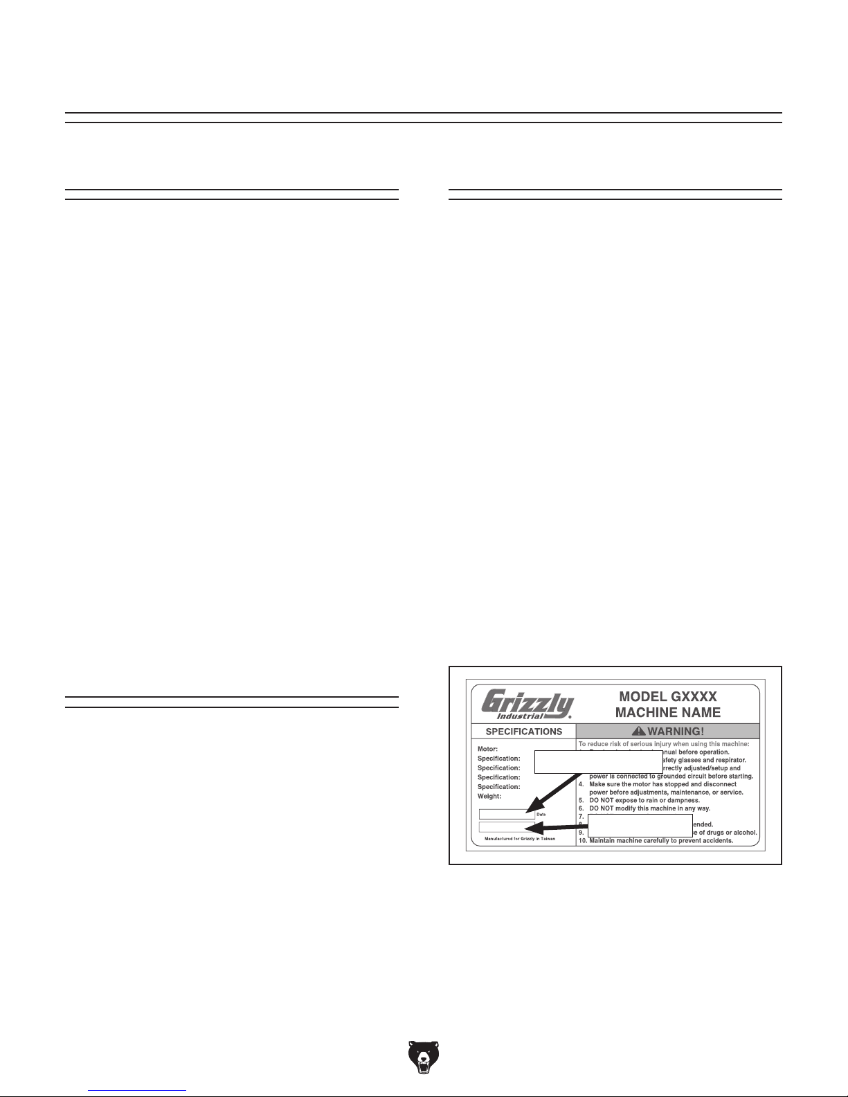
for help. Before calling, make sure you write down
the
from
the machine ID label (see below). This information
is required for us to provide proper tech support,
and it helps us determine if updated documentation is available for your machine.
We stand behind our machines! If you have questions or need help, contact us with the information
below. Before contacting, make sure you get the
serial number
machine ID label. This will help us help you faster.
We want your feedback on this manual. What did
you like about it? Where could it be improved?
Please take a few minutes to give us feedback.
Email: manuals@grizzly.com
Contact Info
and manufacture date from the
Grizzly Technical Support
1815 W. Battlefield
Springfield, MO 65807
Phone: (570) 546-9663
Email: techsupport@grizzly.com
Grizzly Documentation Manager
P.O. Box 2069
Bellingham, WA 98227-2069
Manual Accuracy
made every effort to be exact with the
sometimes the machine
.
,
e post
manual updates for free
www.grizzly.com.
Manufacture Date and Serial Number
Machine Differences
Models G1066R, G1066Z, and G1079R are heavyduty drum sanders with the following differences:
• Model G1066R is a 5 HP, 24" drum sander.
• Model G1066Z is a 5 HP, 24" drum sander
with a variable-speed conveyor and rear
drum height micro-adjustment knobs.
• Model G1079R is a 2 HP, 16" drum sander.
Manufacture Date
Serial Number
-2-
Model G1066R/Z /G1079R (Mfd. Since 02/11)

Identification (G1066R)
To reduce your risk of
serious injury, read this
entire manual BEFORE
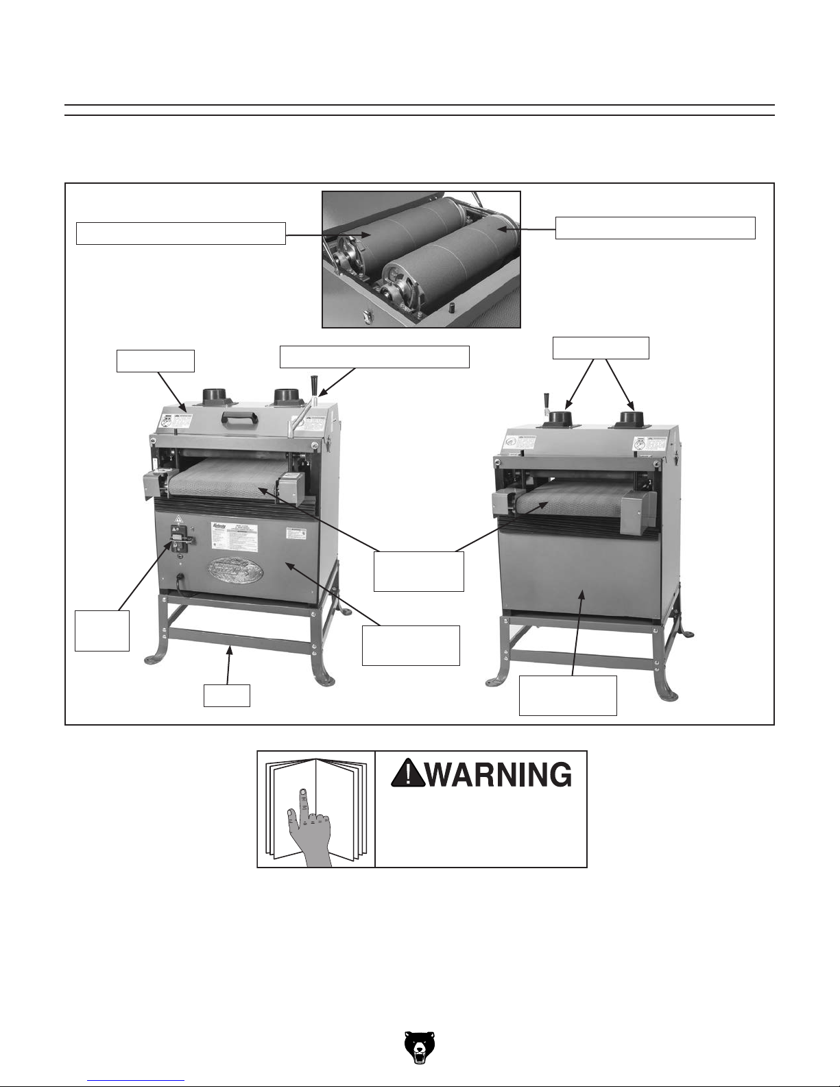
Become familiar with the names and locations of the controls and features shown below to better understand
the instructions in this manual.
Outfeed (Rear) Sanding Drum Infeed (Front) Sanding Drum
4" Dust Ports
Top Cover
On/Off
Switch
Table Height Crank Handle
Front Access
Panel
Conveyor
Table w/Belt
Rear Access
Panel
Model G1066R/Z /G1079R (Mfd. Since 02/11)
using machine.
-3-

Identification (G1066Z)
To reduce your risk of
serious injury, read this
entire manual BEFORE
Become familiar with the names and locations of the controls and features shown below to better understand
the instructions in this manual.
Outfeed (Rear) Sanding Drum
Micro-Adjustment
Lock Lever
Micro-Adjustment
Knob
Infeed (Front) Sanding Drum
Table Height Crank Handle
4" Dust Ports
Control
Panel
Conveyor
Table w/Belt
Front Access
Panel
Rear Access
Top Cover
Panel
-4-
using machine.
Model G1066R/Z /G1079R (Mfd. Since 02/11)
Identification (G1079R)
To reduce your risk of
serious injury, read this
entire manual BEFORE
Become familiar with the names and locations of the controls and features shown below to better understand
the instructions in this manual.
Outfeed (Rear) Sanding Drum
Top Cover
On/Off
Switch
Table Height Crank Handle
Conveyor
Table w/Belt
Front Access
Panel
Infeed (Front) Sanding Drum
4" Dust Ports
Stand
Model G1066R/Z /G1079R (Mfd. Since 02/11)
Rear Access
Panel
using machine.
-5-
Controls &
To reduce your risk of
serious injury, read this
entire manual BEFORE
Components
using machine.
G1066R
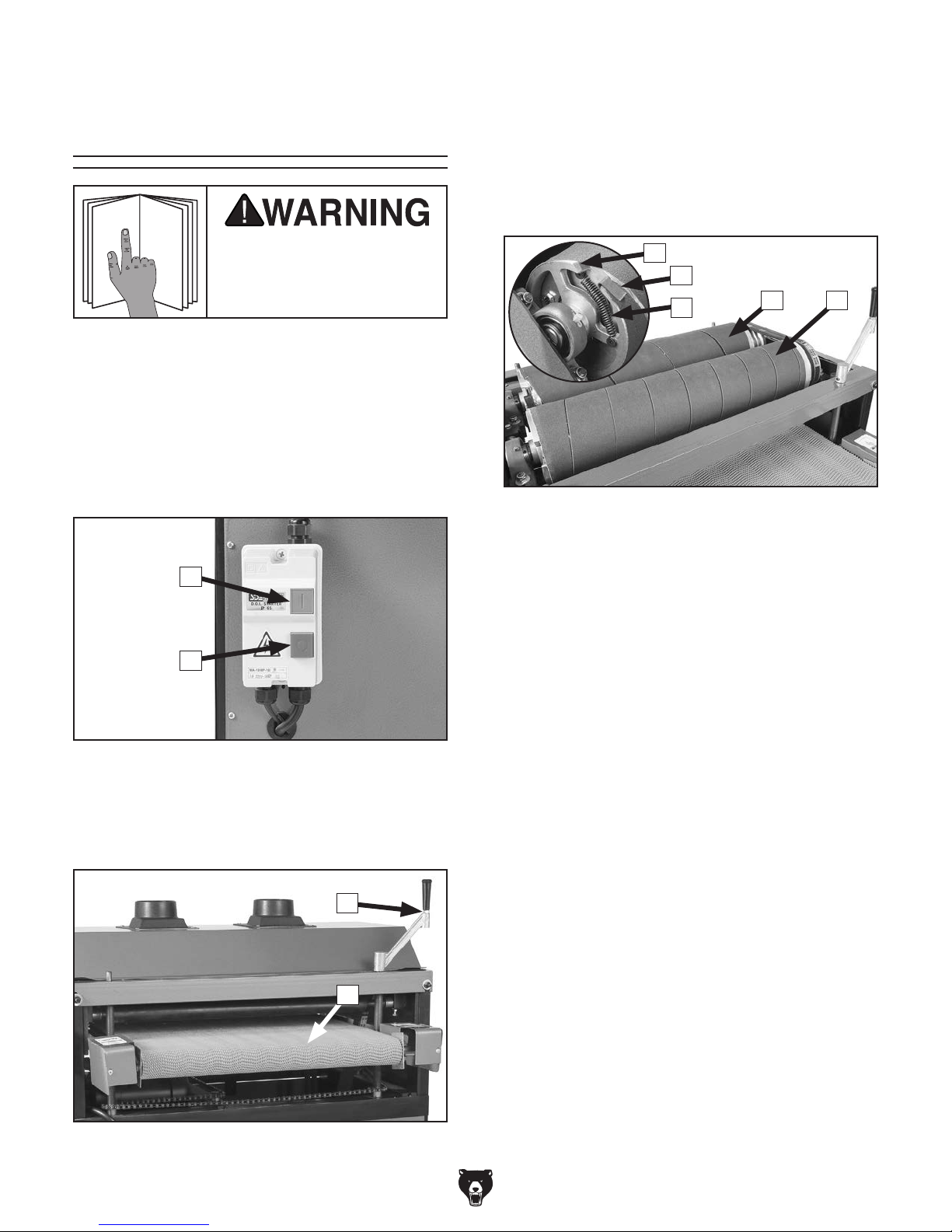
Refer to Figures 45–47 and the following descrip-
tions to become familiar with the basic controls and components of the Model G1066R.
Understanding these items and how they work will
help you understand the rest of the manual and
stay safe when operating this machine.
C. Table Height Crank Handle: Rotate to
raise or lower conveyor table according to
workpiece thickness.
D. Conveyor Table w/Belt (Infeed End):
Height-adjustable table with conveyor belt
that feeds workpieces toward sanding drums.
E
F
G
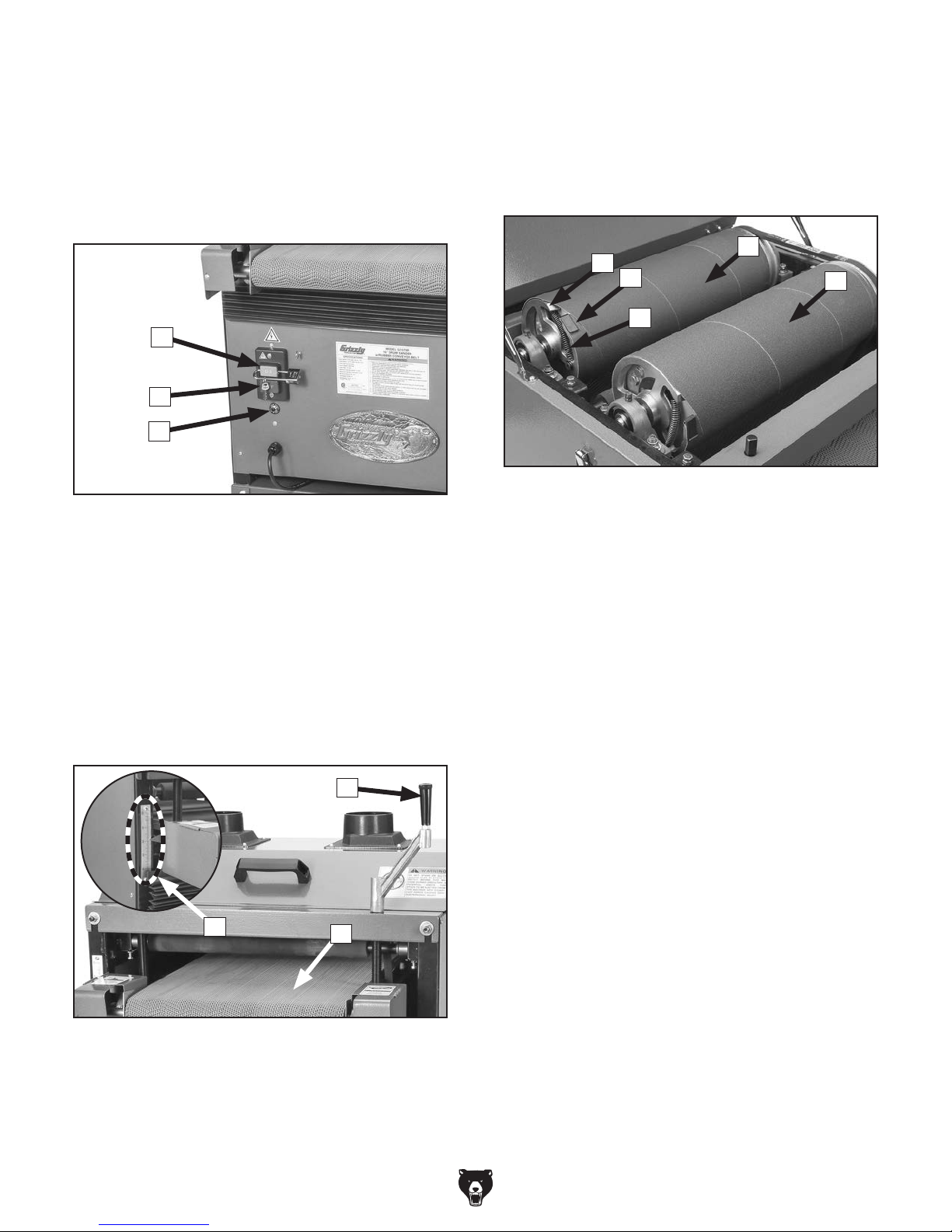
Figure 47. G1066R—drum components.
IH
A
B
Figure 45. G1066R—ON/OFF controls.
A. ON Button: Push to start motor.
B. OFF Button: Push to stop motor.
C
E. Tension Wheel: Tensioned anchor point for
end of sandpaper roll.
F. Sanding Paper Clip: Secures end of sand-
paper roll to tension wheel.
G. Tension Spring: Supplies tension between
sanding drum and tension wheel.
H. Outfeed (Rear) Sanding Drum: Cylindrical
drum with machined surface that is covered
in felt. Typically wrapped with fine grit sandpaper to perform finish sanding portion of
operation.
I. Infeed (Front) Sanding Drum: Cylindrical
drum with machined surface. Typically
wrapped with coarse grit sandpaper to perform thickness sanding portion of operation.
Figure 46. G1066R—front controls.
-6-
D
Model G1066R/Z /G1079R (Mfd. Since 02/11)
G1066Z
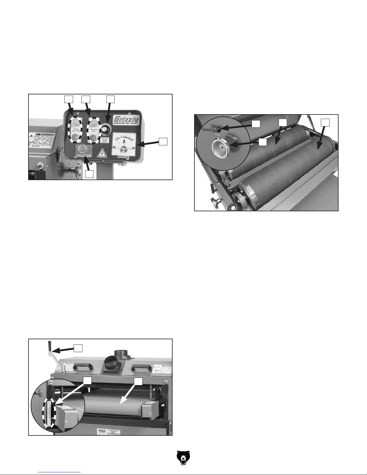
Refer to Figures 48–50 and the following descrip-
tions to become familiar with the basic controls and components of the Model G1066Z.
Understanding these items and how they work will
help you understand the rest of the manual and
stay safe when operating this machine.
A B
A
B
C
F. Table Height Crank Handle: Rotate to
raise or lower conveyor table according to
workpiece thickness.
G. Depth-of-Cut Scale: Indicates distance
between conveyor table and sanding drums.
H. Conveyor Table w/Belt (Infeed End):
Height-adjustable table with conveyor belt
that feeds workpieces toward sanding drums.
D
E
Figure 48. G1066Z—control panel.
A. Sanding Motor ON/OFF Buttons: Push to
start/stop sanding motor.
B. Conveyor Motor ON/OFF Buttons: Push to
start/stop conveyor motor.
C. Conveyor Speed Control: Turn to set con-
veyor belt speed between 0–10 (0–60 RPM).
D. Load Meter: Displays total amp draw of
sanding motor.
E. Emergency Stop Button: Stops motors
when pressed and disables ON buttons.
Remains in depressed position until manually
reset. Reset by twisting button clockwise until
it springs outward.
I
J
Figure 50. G1066Z—drum components.
I. Micro-Adjustment Lock Lever (1 of 2):
Tighten to lock micro-adjustment knob in
place.
J. Micro-Adjustment Knob (1 of 2): Rotate
to make fine height adjustments of outfeed
(rear) sanding drum.
K. Outfeed (Rear) Sanding Drum: Cylindrical
drum with machined surface that is covered
in hook-and-loop material. Typically wrapped
with fine grit sandpaper to perform finish
sanding portion of operation.
K L
F
G
Figure 49. G1066Z—front controls.
Model G1066R/Z /G1079R (Mfd. Since 02/11)
L. Infeed (Front) Sanding Drum: Cylindrical
drum with machined surface that is covered
in hook-and-loop material. Typically wrapped
with coarse grit sandpaper to perform thickness sanding portion of operation.
H
-7-
G1079R
Refer to Figures 51–53 and the following descrip-
tions to become familiar with the basic controls and components of the Model G1079R.
Understanding these items and how they work will
help you understand the rest of the manual and
stay safe when operating this machine.
A
B
C
E. Depth-of-Cut Scale: Indicates distance
between conveyor table and sanding drums.
F. Conveyor Table w/Belt (Infeed End):
Height-adjustable table with conveyor belt
that feeds workpieces toward sanding drums.
J
G
H
I
Figure 53. G1079R—drum components.
K
Figure 51. G1079R—ON/OFF controls.
A. ON Button: Push to start motor. Insert pad-
lock through button to disable (padlock not
included).
B. OFF Button: Push to stop motor.
C. Circuit Breaker Reset Button: Circuit
breaker trips if motor draws excessive current
and overheats. Push to reset circuit breaker
after allowing machine to cool down.
D
E
F
G. Tension Wheel: Tensioned anchor point for
end of sandpaper roll.
H. Sanding Paper Clip: Secures end of sand-
paper roll to tension wheel.
I. Tension Spring: Supplies tension between
sanding drum and tension wheel.
J. Outfeed (Rear) Sanding Drum: Cylindrical
drum with machined surface that is covered
in felt. Typically wrapped with fine grit sandpaper to perform finish sanding portion of
operation.
K. Infeed (Front) Sanding Drum: Cylindrical
drum with machined surface. Typically
wrapped with coarse grit sandpaper to perform thickness sanding portion of operation.
Figure 52. G1079R—front controls.
D. Table Height Crank Handle: Rotate to
raise or lower conveyor table according to
workpiece thickness.
-8-
Model G1066R/Z /G1079R (Mfd. Since 02/11)

Machine Data Sheet (G1066R)
MACHINE DATA
SHEET
Customer Service #: (570) 546-9663 · To Order Call: (800) 523-4777 · Fax #: (800) 438-5901
MODEL G1066R 24" DRUM SANDER
Product Dimensions:
Weight.............................................................................................................................................................. 389 lbs.
Width (side-to-side) x Depth (front-to-back) x Height..................................................................... 37 x 34-1/2 x 43 in.
Footprint (Length x Width)..................................................................................................................... 34-1/2 x 24 in.
Shipping Dimensions:
Type............................................................................................................................. Cardboard Box on Metal Skids
Content........................................................................................................................................................... Machine
Weight.............................................................................................................................................................. 442 lbs.
Length x Width x Height....................................................................................................................... 41 x 38 x 43 in.
Must Ship Upright................................................................................................................................................... Yes
Electrical:
Power Requirement........................................................................................................... 220V, Single-Phase, 60 Hz
Prewired Voltage.................................................................................................................................................. 220V
Full-Load Current Rating........................................................................................................................................ 26A
Minimum Circuit Size.............................................................................................................................................. 30A
Connection Type....................................................................................................................................... Cord & Plug
Power Cord Included.............................................................................................................................................. Yes
Power Cord Length................................................................................................................................................. 8 ft.
Power Cord Gauge......................................................................................................................................... 12 AWG
Plug Included........................................................................................................................................................... No
Recommended Plug Type................................................................................................................................... L6-30
Switch Type.................................................................................................... Magnetic Switch w/Overload Protection
Motors:
Main
Horsepower................................................................................................................................................ 5 HP
Phase............................................................................................................................................ Single-Phase
Amps............................................................................................................................................................ 25A
Speed................................................................................................................................................ 3450 RPM
Type................................................................................................................. TEFC Capacitor-Start Induction
Power Transfer .................................................................................................................................. Belt Drive
Bearings........................................................................................................ Sealed & Permanently Lubricated
Centrifugal Switch/Contacts Type......................................................................................................... External
Feed
Horsepower............................................................................................................................................. 1/4 HP
Phase............................................................................................................................................ Single-Phase
Amps.............................................................................................................................................................. 1A
Speed................................................................................................................................................ 1720 RPM
Type................................................................................................................. TEFC Capacitor-Start Induction
Power Transfer ............................................................................................................................... Chain Drive
Bearings........................................................................................................ Sealed & Permanently Lubricated
Centrifugal Switch/Contacts Type................................................................................................................ N/A
Model G1066R/Z /G1079R (Mfd. Since 02/11)
-9-

Main Specifications:
Operation Information
Number of Sanding Heads............................................................................................................................... 2
Maximum Board Width........................................................................................................................ 23-1/2 in.
Minimum Board Width................................................................................................................................. 2 in.
Maximum Board Thickness................................................................................................................... 4-1/4 in.
Minimum Board Thickness....................................................................................................................... 1/8 in.
Minimum Board Length................................................................................................................................ 9 in.
Sandpaper Speed.............................................................................................................................. 2300 FPM
Conveyor Feed Rate.............................................................................................................................. 11 FPM
Sandpaper Length............................................................................................................................... 95-1/2 in.
Sandpaper Width......................................................................................................................................... 6 in.
Drum Information
Infeed Sanding Drum Type................................................................................................................. Aluminum
Infeed Sanding Drum Size........................................................................................................................... 6 in.
Outfeed Sanding Drum Type.............................................................................................................. Aluminum
Outfeed Sanding Drum Size........................................................................................................................ 6 in.
Construction
Conveyor Belt......................................................................................................................................... Rubber
Body........................................................................................................................................................... Steel
Paint Type/Finish....................................................................................................................... Powder Coated
Other Related Information
Floor To Table Height................................................................................................................................ 31 in.
Sanding Belt Tension.................................................................................................................. Spring Loaded
Number of Pressure Rollers............................................................................................................................. 3
Pressure Roller Type.............................................................................................................................. Rubber
Pressure Roller Size.............................................................................................................................. 1-5/8 in.
Conveyor Belt Length................................................................................................................................ 74 in.
Conveyor Belt Width.................................................................................................................................. 24 in.
Belt Roller Size...................................................................................................................................... 1-7/8 in.
Number of Dust Ports....................................................................................................................................... 2
Dust Port Size.............................................................................................................................................. 4 in.
Mobile Base............................................................................................................................ D2058A, D2246A
Other Specifications:
Country of Origin .............................................................................................................................................. Taiwan
Warranty ........................................................................................................................................................... 1 Year
Approximate Assembly & Setup Time ........................................................................................................ 30 Minutes
Serial Number Location ............................................................................................. ID Label on Center of the Stand
ISO 9001 Factory .................................................................................................................................................... No
Certified by a Nationally Recognized Testing Laboratory (NRTL) .......................................................................... No
Features:
Spring-Loaded Sanding Belt Tension/Sandpaper
Industrial-Duty Rubber Conveyor Belt
Two 4" Dust Ports
11 FPM Conveyor Speed
V-Belt Main Motor; Chain Drive Feed Motor
Dual 4" Aluminum Sanding Drums
Green Powder Coated Paint
Computer Balanced Drums
Four Leadscrew Table Lifting and Lowering System
-10 -
Model G1066R/Z /G1079R (Mfd. Since 02/11)

Machine Data Sheet (G1066Z)
MACHINE DATA
SHEET
Customer Service #: (570) 546-9663 · To Order Call: (800) 523-4777 · Fax #: (800) 438-5901
MODEL G1066Z 24" DRUM SANDER W/ VS
Product Dimensions:
Weight.............................................................................................................................................................. 389 lbs.
Width (side-to-side) x Depth (front-to-back) x Height..................................................................... 50 x 37 x 44-1/2 in.
Footprint (Length x Width)..................................................................................................................... 34-1/2 x 24 in.
Shipping Dimensions:
Type............................................................................................................................. Cardboard Box on Metal Skids
Content........................................................................................................................................................... Machine
Weight.............................................................................................................................................................. 489 lbs.
Length x Width x Height....................................................................................................................... 41 x 38 x 43 in.
Must Ship Upright................................................................................................................................................... Yes
Electrical:
Power Requirement........................................................................................................... 220V, Single-Phase, 60 Hz
Prewired Voltage.................................................................................................................................................. 220V
Full-Load Current Rating........................................................................................................................................ 27A
Minimum Circuit Size.............................................................................................................................................. 30A
Connection Type....................................................................................................................................... Cord & Plug
Power Cord Included.............................................................................................................................................. Yes
Power Cord Length................................................................................................................................................. 8 ft.
Power Cord Gauge......................................................................................................................................... 12 AWG
Plug Included........................................................................................................................................................... No
Recommended Plug Type................................................................................................................................... L6-30
Switch Type............................................................................................ Control Panel w/Magnetic Switch Protection
Motors:
Main
Horsepower................................................................................................................................................ 5 HP
Phase............................................................................................................................................ Single-Phase
Amps............................................................................................................................................................ 25A
Speed................................................................................................................................................ 3450 RPM
Type................................................................................................................. TEFC Capacitor-Start Induction
Power Transfer ...................................................................................................................... Twin V-Belt Drive
Bearings........................................................................................................ Sealed & Permanently Lubricated
Centrifugal Switch/Contacts Type......................................................................................................... External
Feed
Horsepower............................................................................................................................................. 1/3 HP
Phase............................................................................................................................................ Single-Phase
Amps.............................................................................................................................................................. 2A
Speed.................................................................................................................................................... 60 RPM
Type..................................................................................................................................................... Universal
Power Transfer ............................................................................................................................... Chain Drive
Bearings........................................................................................................ Sealed & Permanently Lubricated
Centrifugal Switch/Contacts Type................................................................................................................ N/A
Model G1066R/Z /G1079R (Mfd. Since 02/11)
-11-

Main Specifications:
Operation Information
Number of Sanding Heads............................................................................................................................... 2
Maximum Board Width........................................................................................................................ 23-1/2 in.
Minimum Board Width................................................................................................................................. 2 in.
Maximum Board Thickness................................................................................................................... 4-1/4 in.
Minimum Board Thickness....................................................................................................................... 1/8 in.
Minimum Board Length................................................................................................................................ 9 in.
Sandpaper Speed.............................................................................................................................. 2300 FPM
Conveyor Feed Rate........................................................................................................................ 0 – 20 FPM
Sandpaper Length................................................................................................................................... 176 in.
Sandpaper Width......................................................................................................................................... 3 in.
Drum Information
Infeed Sanding Drum Type................................................................................................................. Aluminum
Infeed Sanding Drum Size........................................................................................................................... 6 in.
Outfeed Sanding Drum Type.............................................................................................................. Aluminum
Outfeed Sanding Drum Size........................................................................................................................ 6 in.
Construction
Conveyor Belt......................................................................................................................................... Rubber
Body........................................................................................................................................................... Steel
Paint Type/Finish....................................................................................................................... Powder Coated
Other Related Information
Floor To Table Height................................................................................................................................ 33 in.
Sanding Belt Tension..................................................................................................................... Hook & Loop
Number of Pressure Rollers............................................................................................................................. 3
Pressure Roller Type.............................................................................................................................. Rubber
Pressure Roller Size.............................................................................................................................. 1-5/8 in.
Conveyor Belt Length................................................................................................................................ 74 in.
Conveyor Belt Width.................................................................................................................................. 24 in.
Belt Roller Size...................................................................................................................................... 1-7/8 in.
Number of Dust Ports....................................................................................................................................... 2
Dust Port Size.............................................................................................................................................. 4 in.
Mobile Base............................................................................................................................ D2058A, D2246A
Other Specifications:
Country of Origin .............................................................................................................................................. Taiwan
Warranty ........................................................................................................................................................... 1 Year
Approximate Assembly & Setup Time ........................................................................................................ 30 Minutes
Serial Number Location ............................................................................................. ID Label on Center of the Stand
ISO 9001 Factory .................................................................................................................................................... No
Certified by a Nationally Recognized Testing Laboratory (NRTL) .......................................................................... No
Features:
Hook and Loop Sanding Belt Tension/Sandpaper
Industrial-Duty Rubber Conveyor Belt
Two 4" Dust Ports
Variable Speed Conveyor
V-Belt Main Motor; Chain Drive Feed Motor
Dual 4" Aluminum Sanding Drums
Green Powder Coated Paint
Computer Balanced Drums
Four Leadscrew Table Lifting and Lowering System
Easy Access Control Panel with Amp Load Meter
External Micro-Adjustment on Outfeed Drum
-12-
Model G1066R/Z /G1079R (Mfd. Since 02/11)

Machine Data Sheet (G1079R)
MACHINE DATA
SHEET
Customer Service #: (570) 546-9663 · To Order Call: (800) 523-4777 · Fax #: (800) 438-5901
MODEL G1079R 16" DRUM SANDER W/ RUBBER
CONVEYOR
Product Dimensions:
Weight.............................................................................................................................................................. 283 lbs.
Width (side-to-side) x Depth (front-to-back) x Height............................................................... 27 x 36-1/2 x 42-1/2 in.
Footprint (Length x Width)............................................................................................................................ 32 x 29 in.
Shipping Dimensions:
Type..................................................................................................................................................... Cardboard Box
Content........................................................................................................................................................... Machine
Weight.............................................................................................................................................................. 304 lbs.
Length x Width x Height....................................................................................................................... 41 x 30 x 34 in.
Must Ship Upright................................................................................................................................................... Yes
Electrical:
Power Requirement........................................................................................................... 220V, Single-Phase, 60 Hz
Prewired Voltage.................................................................................................................................................. 220V
Full-Load Current Rating....................................................................................................................................... 9.5A
Minimum Circuit Size.............................................................................................................................................. 15A
Connection Type....................................................................................................................................... Cord & Plug
Power Cord Included.............................................................................................................................................. Yes
Power Cord Length................................................................................................................................................. 8 ft.
Power Cord Gauge......................................................................................................................................... 14 AWG
Plug Included........................................................................................................................................................... No
Recommended Plug Type..................................................................................................................................... 6-15
Switch Type.................................................................................................. Paddle Safety Switch w/Removable Key
Motors:
Main
Horsepower................................................................................................................................................ 2 HP
Phase............................................................................................................................................ Single-Phase
Amps........................................................................................................................................................... 8.5A
Speed................................................................................................................................................ 3450 RPM
Type................................................................................................................. TEFC Capacitor-Start Induction
Power Transfer ............................................................................................................................... V-Belt Drive
Bearings........................................................................................................ Sealed & Permanently Lubricated
Centrifugal Switch/Contacts Type......................................................................................................... External
Feed
Horsepower............................................................................................................................................. 1/4 HP
Phase............................................................................................................................................ Single-Phase
Amps.............................................................................................................................................................. 1A
Speed................................................................................................................................................ 3450 RPM
Type................................................................................................................. TEFC Capacitor-Start Induction
Power Transfer ............................................................................................................................... Chain Drive
Bearings........................................................................................................ Sealed & Permanently Lubricated
Centrifugal Switch/Contacts Type................................................................................................................ N/A
Model G1066R/Z /G1079R (Mfd. Since 02/11)
-13-

Main Specifications:
Four Leadscrew Table Lifting and Lowering System
Operation Information
Number of Sanding Heads............................................................................................................................... 2
Maximum Board Width........................................................................................................................ 15-3/8 in.
Minimum Board Width................................................................................................................................. 2 in.
Maximum Board Thickness................................................................................................................... 3-1/2 in.
Minimum Board Thickness....................................................................................................................... 1/4 in.
Minimum Board Length................................................................................................................................ 9 in.
Sandpaper Speed.............................................................................................................................. 2100 FPM
Conveyor Feed Rate.............................................................................................................................. 11 FPM
Sandpaper Length............................................................................................................................... 71-1/2 in.
Sandpaper Width......................................................................................................................................... 6 in.
Drum Information
Infeed Sanding Drum Type................................................................................................................. Aluminum
Infeed Sanding Drum Size........................................................................................................................... 6 in.
Outfeed Sanding Drum Type.............................................................................................................. Aluminum
Outfeed Sanding Drum Size........................................................................................................................ 6 in.
Construction
Conveyor Belt......................................................................................................................................... Rubber
Body........................................................................................................................................................... Steel
Base........................................................................................................................................................... Steel
Paint Type/Finish....................................................................................................................... Powder Coated
Other Related Information
Floor To Table Height................................................................................................................................ 34 in.
Sanding Belt Tension.................................................................................................................. Spring Loaded
Number of Pressure Rollers............................................................................................................................. 3
Pressure Roller Type.............................................................................................................................. Rubber
Pressure Roller Size.............................................................................................................................. 1-5/8 in.
Conveyor Belt Length................................................................................................................................ 73 in.
Conveyor Belt Width.................................................................................................................................. 16 in.
Belt Roller Size...................................................................................................................................... 1-7/8 in.
Number of Dust Ports....................................................................................................................................... 2
Dust Port Size.............................................................................................................................................. 4 in.
Mobile Base............................................................................................................................ D2058A, D2246A
Other Specifications:
Country of Origin .............................................................................................................................................. Taiwan
Warranty ........................................................................................................................................................... 1 Year
Approximate Assembly & Setup Time ........................................................................................................ 30 Minutes
Serial Number Location ............................................................................................. ID Label on Center of the Stand
ISO 9001 Factory .................................................................................................................................................... No
Certified by a Nationally Recognized Testing Laboratory (NRTL) ......................................................................... Yes
Features:
Spring-Loaded Sanding Belt Tension/Sandpaper
Industrial-Duty Rubber Conveyor Belt
Two 4" Dust Ports
11 FPM Conveyor Speed
V-Belt Main Motor; Chain Drive Feed Motor
Dual 6" Aluminum Sanding Drums
Green Powder Coated Paint
Computer-Balanced, Non-Rubberized Drums
Includes Stand
-14-
Model G1066R/Z /G1079R (Mfd. Since 02/11)
SECTION 1: SAFETY
For Your Own Safety, Read Instruction
Manual Before Operating This Machine
The purpose of safety symbols is to attract your attention to possible hazardous conditions.
This manual uses a series of symbols and signal words intended to convey the level of importance of the safety messages. The progression of symbols is described below. Remember that
safety messages by themselves do not eliminate danger and are not a substitute for proper
accident prevention measures. Always use common sense and good judgment.
Indicates an imminently hazardous situation which, if not avoided,
WILL result in death or serious injury.
Indicates a potentially hazardous situation which, if not avoided,
COULD result in death or serious injury.
Indicates a potentially hazardous situation which, if not avoided,
MAY result in minor or moderate injury. It may also be used to alert
against unsafe practices.
Alerts the user to useful information about proper operation of the
NOTICE
machine to avoid machine damage.
Safety Instructions for Machinery
OWNER’S MANUAL. Read and understand this
owner’s manual BEFORE using machine.
TRAINED OPERATORS ONLY. Untrained operators have a higher risk of being hurt or killed.
Only allow trained/supervised people to use this
machine. When machine is not being used, disconnect power, remove switch keys, or lock-out
machine to prevent unauthorized use—especially
around children. Make your workshop kid proof!
DANGEROUS ENVIRONMENTS. Do not use
machinery in areas that are wet, cluttered, or have
poor lighting. Operating machinery in these areas
greatly increases the risk of accidents and injury.
MENTAL ALERTNESS REQUIRED. Full mental
alertness is required for safe operation of machinery. Never operate under the influence of drugs or
alcohol, when tired, or when distracted.
ELECTRICAL EQUIPMENT INJURY RISKS.
You can be shocked, burned, or killed by touching
live electrical components or improperly grounded
machinery. To reduce this risk, only allow qualified
service personnel to do electrical installation or
repair work, and always disconnect power before
accessing or exposing electrical equipment.
DISCONNECT POWER FIRST.
nect machine from power supply BEFORE making adjustments, changing tooling, or servicing
machine. This prevents an injury risk from unintended startup or contact with live electrical components.
EYE PROTECTION. Always wear ANSI-approved
safety glasses or a face shield when operating or
observing machinery to reduce the risk of eye
injury or blindness from flying particles. Everyday
eyeglasses are NOT approved safety glasses.
Always discon-
Model G1066R/Z /G1079R (Mfd. Since 02/11)
-15-

WEARING PROPER APPAREL. Do not wear
clothing, apparel or jewelry that can become
entangled in moving parts. Always tie back or
cover long hair. Wear non-slip footwear to reduce
risk of slipping and losing control or accidentally
contacting cutting tool or moving parts.
HAZARDOUS DUST. Dust created by machinery
operations may cause cancer, birth defects, or
long-term respiratory damage. Be aware of dust
hazards associated with each workpiece material. Always wear a NIOSH-approved respirator to
reduce your risk.
HEARING PROTECTION. Always wear hearing protection when operating or observing loud
machinery. Extended exposure to this noise
without hearing protection can cause permanent
hearing loss.
REMOVE ADJUSTING TOOLS. Tools left on
machinery can become dangerous projectiles
upon startup. Never leave chuck keys, wrenches,
or any other tools on machine. Always verify
removal before starting!
USE CORRECT TOOL FOR THE JOB. Only use
this tool for its intended purpose—do not force
it or an attachment to do a job for which it was
not designed. Never make unapproved modifications—modifying tool or using it differently than
intended may result in malfunction or mechanical
failure that can lead to personal injury or death!
AWKWARD POSITIONS. Keep proper footing
and balance at all times when operating machine.
Do not overreach! Avoid awkward hand positions
that make workpiece control difficult or increase
the risk of accidental injury.
CHILDREN & BYSTANDERS. Keep children and
bystanders at a safe distance from the work area.
Stop using machine if they become a distraction.
GUARDS & COVERS. Guards and covers reduce
accidental contact with moving parts or flying
debris. Make sure they are properly installed,
undamaged, and working correctly BEFORE
operating machine.
FORCING MACHINERY. Do not force machine.
It will do the job safer and better at the rate for
which it was designed.
NEVER STAND ON MACHINE. Serious injury
may occur if machine is tipped or if the cutting
tool is unintentionally contacted.
STABLE MACHINE. Unexpected movement during operation greatly increases risk of injury or
loss of control. Before starting, verify machine is
stable and mobile base (if used) is locked.
USE RECOMMENDED ACCESSORIES. Consult
this owner’s manual or the manufacturer for recommended accessories. Using improper accessories will increase the risk of serious injury.
UNATTENDED OPERATION. To reduce the
risk of accidental injury, turn machine OFF and
ensure all moving parts completely stop before
walking away. Never leave machine running
while unattended.
MAINTAIN WITH CARE. Follow all maintenance
instructions and lubrication schedules to keep
machine in good working condition. A machine
that is improperly maintained could malfunction,
leading to serious personal injury or death.
DAMAGED PARTS. Regularly inspect machine
for damaged, loose, or mis-adjusted parts—or
any condition that could affect safe operation.
Immediately repair/replace BEFORE operating
machine. For your own safety, DO NOT operate
machine with damaged parts!
MAINTAIN POWER CORDS. When disconnecting cord-connected machines from power, grab
and pull the plug—NOT the cord. Pulling the cord
may damage the wires inside. Do not handle
cord/plug with wet hands. Avoid cord damage by
keeping it away from heated surfaces, high traffic
areas, harsh chemicals, and wet/damp locations.
EXPERIENCING DIFFICULTIES. If at any time
you experience difficulties performing the intended operation, stop using the machine! Contact our
Technical Support at (570) 546-9663.
-16 -
Model G1066R/Z /G1079R (Mfd. Since 02/11)

Additional Safety for Drum Sanders
Serious injury or death can occur from getting hands trapped between workpiece and conveyor
table and being pulled into machine, or becoming entangled in rotating parts inside machine.
Workpieces thrown by sander can strike nearby operator or bystanders with significant force.
Long-term respiratory damage can occur from using sander without proper use of a respirator.
To reduce the risk of these hazards, operator and bystanders MUST completely heed the
hazards and warnings below.
FEEDING WORKPIECE. Placing fingers between
workpiece and conveyor can result in pinching
injuries, or possibly getting trapped and pulled into
sanding area of machine. DO NOT place fingers
under bottom of workpiece while feeding it into
sander.
SANDING DUST. Sanding creates large amounts
of fine airborne dust that can lead to eye injury
or serious respiratory illness. Reduce your risk
by always wearing approved eye and respiratory
protection when sanding. Never operate without
adequate dust collection system in place and running. However, dust collection is not a substitute for
using a respirator.
POWER DISCONNECT. An accidental startup
while changing sanding belts or performing adjustments or maintenance can result in serious entanglement or abrasion injuries. Make sure machine
is turned OFF, disconnected from power and air,
and all moving parts are completely stopped before
changing belts, doing adjustments, or performing
maintenance.
SANDPAPER CONTACT. Rotating sandpaper can
remove a large amount of flesh quickly. Keep hands
away from rotating sanding drum(s) during operation. Never touch moving sandpaper.
AVOIDING ENTANGLEMENT. Tie back long
hair, remove jewelry, and do not wear loose
clothing or gloves. These can easily get caught
in moving parts. Never reach inside machine or
try to clear jammed workpiece while machine is
operating. Keep all guards in place and secure.
WORKPIECE MATERIAL. This sander is
designed to sand only natural wood products or
man-made products made from natural wood
fiber. DO NOT sand any metal products.
WORKPIECE INSPECTION. Nails, staples,
knots, or other imperfections in workpiece can be
dislodged and thrown from sander at high rate of
speed into operator or bystanders, or cause damage to sandpaper or sander. Never try to sand
stock that has embedded foreign objects or questionable imperfections.
KICKBACK. Occurs when a workpiece is ejected
out the front of sander at a high rate of speed
toward operator or bystanders. To reduce risk
of kickback-related injuries, always stay out of
workpiece path, only feed one board at a time,
and always make sure pressure rollers are properly adjusted below sanding roller. Never sand
workpieces below minimum specifications listed
in Machine Data Sheet.
Like all machinery there is potential danger
when operating this machine. Accidents
are frequently caused by lack of familiarity
or failure to pay attention. Use this machine
with respect and caution to decrease the
risk of operator injury. If normal safety precautions are overlooked or ignored, serious personal injury may occur.
Model G1066R/Z /G1079R (Mfd. Since 02/11)
No list of safety guidelines can be complete. Every shop environment is different.
Always consider safety first, as it applies
to your individual working conditions. Use
this and other machinery with caution and
respect. Failure to do so could result in
serious personal injury, damage to equipment, or poor work results.
-17-

SECTION 2: POWER SUPPLY
Before installing the machine, consider the availability and proximity of the required power supply
circuit. If an existing circuit does not meet the
requirements for this machine, a new circuit must
be installed. To minimize the risk of electrocution,
fire, or equipment damage, installation work and
electrical wiring must be done by an electrician or
qualified service personnel in accordance with all
applicable codes and standards.
or equipment damage
may occur if machine is
not properly grounded
and connected to power
The full-load current rating is the amperage a
machine draws at 100% of the rated output power.
On machines with multiple motors, this is the
amperage drawn by the largest motor or sum of all
motors and electrical devices that might operate
at one time during normal operations.
The full-load current is not the maximum amount
of amps that the machine will draw. If the machine
is overloaded, it will draw additional amps beyond
the full-load rating.
If the machine is overloaded for a sufficient length
of time, damage, overheating, or fire may result—
especially if connected to an undersized circuit.
To reduce the risk of these hazards, avoid overloading the machine during operation and make
sure it is connected to a power supply circuit that
meets the specified circuit requirements.
For your own safety and protection of
Note: Circuit requirements in this manual apply to
a dedicated circuit—where only one machine will
be running on the circuit at a time. If machine will
be connected to a shared circuit where multiple
machines may be running at the same time, consult an electrician or qualified service personnel to
ensure circuit is properly sized for safe operation.
This machine is prewired to operate on a power
supply circuit that has a verified ground and meets
the following requirements:
A power supply circuit includes all electrical
equipment between the breaker box or fuse panel
in the building and the machine. The power supply circuit used for this machine must be sized to
safely handle the full-load current drawn from the
machine for an extended period of time. (If this
machine is connected to a circuit protected by
fuses, use a time delay fuse marked D.)
Power Supply
Availability
Electrocution, fire, shock,
Circuit Requirements for 220V
Nominal Voltage .........20 8V, 2 20V, 230V, 24 0V
Cycle .......................................................... 60 Hz
Phase ........................................... Single-Phase
Power Supply Circuit (G1066R/ Z) ..... 30 Amps
Power Supply Circuit (G1079R ) ........ 15 Amps
Plug/Receptacle (G1066R / Z) .......NEMA L6-30
Plug/Receptacle (G1079R) ............ NEMA 6-15
Cord (G1066R /Z) ...............................................
.................."S"-Ty p e, 3-Wire, 12 AWG, 300 VAC
Cord (G1079R) "S"-Type , 3-Wire, 14 AWG, 300
supply.
Full-Load Current Rating
G1066R Amp Draw at 220V ............... 26 Amps
G1066Z Amp Draw at 220V ................ 27 Amps
G1079R Amp Draw at 220V .............. 9.5 Amps
-18-
property, consult an electrician if you are
unsure about wiring practices or electrical
codes in your area.
Model G1066R/Z /G1079R (Mfd. Since 02/11)
We do not recommend using an extension cord
with this machine.
cord, only use it if absolutely necessary and only
on a temporary basis.
Extension cords cause voltage drop, which can
damage electrical components and shorten motor
life. Voltage drop increases as the extension cord
size gets longer and the gauge size gets smaller
(higher gauge numbers indicate smaller sizes).
Any extension cord used with this machine must
be in good condition and contain a ground wire
and matching plug/receptacle. Additionally, it must
meet the following size requirements:
Improper connection of the equipment-grounding
wire can result in a risk of electric shock. The
wire with green insulation (with or without yellow
stripes) is the equipment-grounding wire. If repair
or replacement of the power cord or plug is necessary, do not connect the equipment-grounding
wire to a live (current carrying) terminal.
Check with a qualified electrician or service personnel if you do not understand these grounding
requirements, or if you are in doubt about whether
the tool is properly grounded. If you ever notice
that a cord or plug is damaged or worn, disconnect it from power, and immediately replace it with
a new one.
Grounding Instructions
This machine MUST be grounded. In the event
of certain malfunctions or breakdowns, grounding
reduces the risk of electric shock by providing a
path of least resistance for electric current.
The power cord and plug specified under “Circuit
Requirements for 220V”
has an equipment-grounding wire and a grounding prong. The plug must only be inserted into
a matching receptacle (outlet) that is properly
installed and grounded in accordance with all
local codes and ordinances (see figure below).
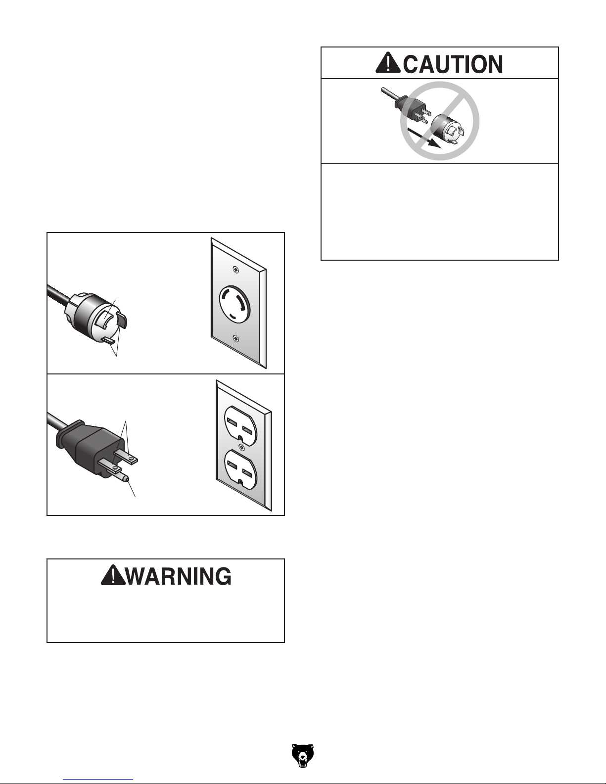
No adapter should be used with plug. If
Serious injury could occur if you connect
process. DO NOT connect to power until
on the previous page
L6-30 GROUNDED
LOCKING
RECEPTACLE
Grounding Prong
is Hooked
L6-30
LOCKING
PLUG
plug does not fit available receptacle, or if
machine must be reconnected for use on a
different type of circuit, reconnection must
be performed by an electrician or qualified
service personnel, and it must comply with
all local codes and ordinances.
Current Carrying Prongs
GROUNDED
6-15 RECEPTACLE
Current Carrying Prongs
6-15 PLUG
Grounding Pin
Figure 54. Typical L6-30 (G1066R, G1066Z) and
6-15 (G1079R) plugs and receptacles.
machine to power before completing setup
instructed later in this manual.
Model G1066R/Z /G1079R (Mfd. Since 02/11)
Extension Cords
If you must use an extension
Minimum Gauge Size (G1066R /Z) ......12 AWG
Minimum Gauge Size (G1079R) ..........14 AWG
Maximum Length (Shorter is Better).......50 ft.
-19 -

SECTION 3: SETUP
This machine was carefully packaged for safe
transport. When unpacking, separate all enclosed
items from packaging materials and inspect them
for shipping damage.
,
please
IMPORTANT:
you are completely satisfied with the machine and
have resolved any issues between Grizzly or the
shipping agent. You MUST have the original pack-
aging to file a freight claim. It is also extremely
helpful if you need to return your machine later.
Keep children and pets away
from plastic bags or packing
materials shipped with this
get help from other people
The following items are needed, but not included,
for the setup/assembly of this machine.
Needed for Setup
This machine presents
serious injury hazards
to untrained users. Read
through this entire manual to become familiar with
the controls and operations before starting the
machine!
Wear safety glasses during
the entire setup process!
HEAVY LIF T!
Straining or crushing injury
may occur from improperly
lifting machine or some of
its parts. To reduce this risk,
Description Qty
• Additional Person ....................................... 1
• Safety Glasses (for each person) ............... 1
• Leather Gloves (for each person) ........ 1 Pair
• Cleaner/Degreaser ..................... As Needed
• Disposable Shop Rags ............... As Needed
• Lifting Equipment (Min. 600 lb. rating):
— Forklift or Hoist ....................................... 1
— Lifting Slings ........................................... 2
• Precision Straightedge 4' ........................... 1
• Phillips Screwdriver #2 ............................... 1
• Wrench or Socket
• Double-Sided Tape..................... As Needed
• Dust-Collection System .............................. 1
• 4" Dust Hose (length as needed) ............... 2
• 4" Hose Clamp ........................................... 2
1
⁄2 " ................................. 1
and use a forklift (or other
lifting equipment) rated for
weight of this machine.
-20-
Unpacking
If items are damaged
call us immediately at (570) 546-9663.
Save all packaging materials until
SUFFOCATION HAZARD!
machine.
Model G1066R/Z /G1079R (Mfd. Since 02/11)
Inventory
The following is a list of items shipped with your
machine. Before beginning setup, lay these items
out and inventory them.
If any non-proprietary parts are missing (e.g. a
nut or a washer), we will gladly replace them; or
for the sake of expediency, replacements can be
obtained at your local hardware store.
Site Considerations
Site Considerations
Weight Load
Refer to the Machine Data Sheet for the weight
of your machine. Make sure that the surface upon
which the machine is placed will bear the weight
of the machine, additional equipment that may
be installed on the machine, and the heaviest
workpiece that will be used. Additionally, consider
the weight of the operator and any dynamic loading that may occur when operating the machine.
NOTICE
If you cannot find an item on this list, carefully check around/inside the machine and
packaging materials. Often, these items get
lost in packaging materials while unpacking or they are pre-installed at the factory.
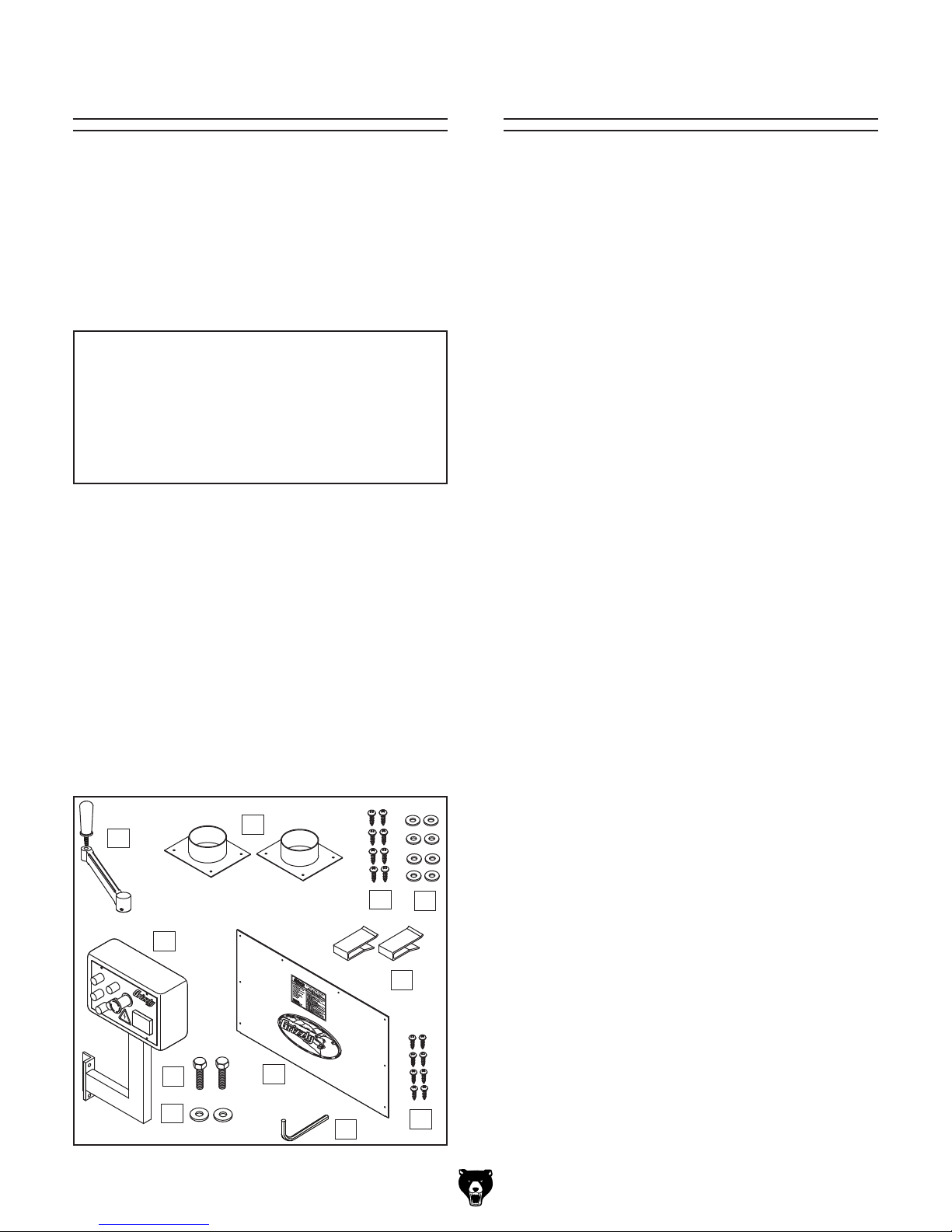
Box 1 (Figure 55) Qty
A. Drum Sander (Not Shown) ......................... 1
B. Crank Handle ............................................. 1
C. 4" Dust Ports .............................................. 2
D. Self-Tapping Screws #8 x
E. Flat Washers 10mm ................................... 8
F. Sandpaper Clips (G1066R, G1079R) ......... 2
G. Control Panel (G1066Z) .............................. 1
H. Hex Bolts
I. Flat Washers
J. Front Panel (G1066Z) ................................. 1
K. Self-Tapping Screws #8 x
L. Hex Wrench 3mm ....................................... 1
B
5
⁄16"-18 x 1" (G1066Z) ................. 2
5
⁄16" (G1066Z) ....................... 2
C
G
H
I
1
⁄2 " ..................... 8
3
⁄8" (G1066Z) ..... 8
J
L
Space Allocation
Consider the largest size of workpiece that will
be processed through this machine and provide
enough space around the machine for adequate
operator material handling or the installation of
auxiliary equipment. With permanent installations,
leave enough space around the machine to open
or remove doors/covers as required by the maintenance and service described in this manual.
Physical Environment
The physical environment where the machine is
operated is important for safe operation and longevity of machine components. For best results,
operate this machine in a dry environment that is
free from excessive moisture, hazardous chemicals, airborne abrasives, or extreme conditions.
Extreme conditions for this type of machinery are
generally those where the ambient temperature
range exceeds 41°–104°F; the relative humidity
range exceeds 20%–95% (non-condensing); or
the environment is subject to vibration, shocks,
or bumps.
Electrical Installation
Place this machine near an existing power source.
Make sure all power cords are protected from
D
E
F
K
traffic, material handling, moisture, chemicals, or
other hazards. Make sure to leave enough space
around machine to disconnect power supply or
apply a lockout/tagout device, if required.
Lighting
Lighting around the machine must be adequate
enough that operations can be performed safely.
Shadows, glare, or strobe effects that may distract
or impede the operator must be eliminated.
Model G1066R/Z /G1079R (Mfd. Since 02/11)
Figure 55. Inventory.
-21-
 Loading...