


MODEL G1053/G1054
DIVIDING HEAD
OWNER'S MANUAL
COPYRIGHT © MAY, 2009 BY GRIZZLY INDUSTRIAL, INC., REVISED JULY, 2009 (TS)
WARNING: NO PORTION OF THIS MANUAL MAY BE REPRODUCED IN ANY SHAPE
OR FORM WITHOUT THE WRITTEN APPROVAL OF GRIZZLY INDUSTRIAL, INC.
(FOR MODELS MANUFACTURED SINCE 1/09) #DDTS11699 PRINTED IN TAI WAN

This manual provides critical safety instructions on the proper setup,
operation, maintenance, and service of this machine/tool. Save this
document, refer to it often, and use it to instruct other operators.
Failure to read, understand and follow the instructions in this manual
may result in fire or serious personal injury—including amputation,
electrocution, or death.
The owner of this machine/tool is solely responsible for its safe use.
This responsibility includes but is not limited to proper installation in
a safe environment, personnel training and usage authorization,
proper inspection and maintenance, manual availability and comprehension, application of safety devices, cutting/sanding/grinding tool
integrity, and the usage of personal protective equipment.
The manufacturer will not be held liable for injury or property damage
from negligence, improper training, machine modifications or misuse.
Some dust created by power sanding, sawing, grinding, drilling, and
other construction activities contains chemicals known to the State
of California to cause cancer, birth defects or other reproductive
harm. Some examples of these chemicals are:
• Lead from lead-based paints.
• Crystalline silica from bricks, cement and other masonry products.
• Arsenic and chromium from chemically-treated lumber.
Your risk from these exposures varies, depending on how often you
do this type of work. To reduce your exposure to these chemicals:
Work in a well ventilated area, and work with approved safety equipment, such as those dust masks that are specially designed to filter
out microscopic particles.

Table of Contents
INTRODUCTION ............................................................................................................................... 2
Manual Accuracy ........................................................................................................................ 2
Contact Info ................................................................................................................................ 2
Functional Description ................................................................................................................ 2
Identification ............................................................................................................................... 3
Specifications ............................................................................................................................. 4
SECTION 1: SAFETY ....................................................................................................................... 5
Safety Instructions for Machinery ............................................................................................... 5
SECTION 2: SETUP ......................................................................................................................... 7
Needed for Setup ....................................................................................................................... 7
Unpacking .................................................................................................................................. 7
Inventory ..................................................................................................................................... 8
Clean Up .................................................................................................................................... 8
Installation .................................................................................................................................. 9
Centering Spindle ..................................................................................................................... 10
Tailstock Center Height ............................................................................................................ 11
SECTION 3: OPERATIONS ........................................................................................................... 12
Basic Controls .......................................................................................................................... 12
Changing Dividing Plates ......................................................................................................... 13
Tilting Spindle ........................................................................................................................... 14
Spindle Center.......................................................................................................................... 14
Center Dog ............................................................................................................................... 15
Chuck Backing Plate ................................................................................................................ 15
Setting Index Pin ...................................................................................................................... 16
Using Dividing Plates ............................................................................................................... 16
Disengaging Worm ................................................................................................................... 20
Cutting Angles .......................................................................................................................... 21
SECTION 4: ACCESSORIES ......................................................................................................... 22
SECTION 5: MAINTENANCE......................................................................................................... 23
Schedule .................................................................................................................................. 23
Cleaning ................................................................................................................................... 23
Lubrication ................................................................................................................................ 23
Surface Care ............................................................................................................................ 24
Bearing Preload........................................................................................................................ 25
SECTION 6: PARTS ....................................................................................................................... 26
G1053/G1054 Main .................................................................................................................. 26
G1053 Parts List ...................................................................................................................... 27
G1054 Parts List ...................................................................................................................... 28
WARRANTY AND RETURNS ........................................................................................................ 33

INTRODUCTION
Manual Accuracy
We are proud to offer this manual with your new
dividing head! We've made every effort to be exact
with the instructions, specifications, drawings, and
photographs of the dividing head we used when
writing this manual. However, sometimes errors
do happen and we apologize for them.
Also, owing to our policy of continuous improvement, your dividing head may not exactly
match the manual. If you find this to be the case,
and the difference between the manual and dividing head leaves you in doubt, check our website
for the latest manual update or call technical support for help.
For your convenience, we post all available manuals and manual updates for free on our website at
www.grizzly.com. Any updates to your model of
dividing head will be reflected in these documents
as soon as they are complete.
Contact Info
We stand behind our machines. If you have any
service questions, parts requests or general questions about the dividing head, please call or write
us at the location listed below.
Grizzly Industrial, Inc.
1203 Lycoming Mall Circle
Muncy, PA 17756
Phone: (570) 546-9663
Fax: (800) 438-5901
E-Mail: techsupport@grizzly.com
If you have any comments regarding this manual,
please write to us at the address below:
C
/O Technical Documentation Manager
Grizzly Industrial, Inc.
P.O. Box 2069
Bellingham, WA 98227-2069
Email: manuals@grizzly.com
Functional
Description
The Model G1053/G1054 Dividing Head offers
precision rotary positioning of the workpiece for
machining various spacing patterns.
A pattern of drilled holes radially or on the face
of the workpiece may be produced with exact
spacing. Other typical operations include milling
of spur gears, sprockets, cogs, and circular slots,
as well as, grinding punches or other hardened
materials. These tasks would be difficult to perform without the use of a dividing head.
This dividing head is supplied with a 24-hole
direct indexing plate and index system that allows
divisions of 2, 3, 4, 6, 8, 12, and 24.
-2-
Model G1053/G1054 (Mfg. 1/09+)

Scale Index
Dividing Plate
Sector Arms
Sector Spring
Crank Handle
Identification
Head Tilt Scale
Threaded Spindle
Degree Index Pointer
Direct Indexing Plate
Dead Center
Mounting
Base
Degree Scale
Direct Indexing Lever
Spindle Lock Lever
Head Tilt
Locking Hex Nuts
Figure 1. Model G1053/G1054 identification.
Model G1053/G1054 (Mfg. 1/09+)
-3-

Specifications
Description G1053 G1054
Overall Length 7.72 " 9.96"
Overall Width 7. 25 " 8.5"
Overall Height 6.61" 8.66"
Center Height 3.94" 5.04"
Spindle Taper Brown & Sharpe #7 Brown & Sharpe #9
Spindle Bore 0.63" .078"
Tailstock Length 7.17 " 7.17 "
Tailstock Width 3.23" 3.23"
Tailstock Height 4.84" 5.24"
Spindle Thread 1
Shipping Weight 41 lb s . 69 lbs.
No. of Dividing Plates 3 3
Country of Origin Taiwan Taiwan
1
⁄2 "-8 1 1⁄2 "-8
-4-
Model G1053/G1054 (Mfg. 1/09+)

SECTION 1: SAFETY
For Your Own Safety, Read Instruction
Manual Before Operating This Machine
The purpose of safety symbols is to attract your attention to possible hazardous conditions.
This manual uses a series of symbols and signal words intended to convey the level of importance of the safety messages. The progression of symbols is described below. Remember that
safety messages by themselves do not eliminate danger and are not a substitute for proper
accident prevention measures. Always use common sense and good judgment.
Indicates an imminently hazardous situation which, if not avoided,
WILL result in death or serious injury.
Indicates a potentially hazardous situation which, if not avoided,
COULD result in death or serious injury.
Indicates a potentially hazardous situation which, if not avoided,
MAY result in minor or moderate injury. It may also be used to alert
against unsafe practices.
This symbol is used to alert the user to useful information about
NOTICE
proper operation of the machine.
Safety Instructions for Machinery
OWNER’S MANUAL. Read and understand this
owner’s manual BEFORE using machine.
TRAINED OPERATORS ONLY. Untrained operators have a higher risk of being hurt or killed.
Only allow trained/supervised people to use this
machine. When machine is not being used, disconnect power, remove switch keys, or lock-out
machine to prevent unauthorized use—especially
around children. Make workshop kid proof!
DANGEROUS ENVIRONMENTS. Do not use
machinery in areas that are wet, cluttered, or have
poor lighting. Operating machinery in these areas
greatly increases the risk of accidents and injury.
MENTAL ALERTNESS REQUIRED. Full mental
alertness is required for safe operation of machinery. Never operate under the influence of drugs or
alcohol, when tired, or when distracted.
ELECTRICAL EQUIPMENT INJURY RISKS. You
can be shocked, burned, or killed by touching live
electrical components or improperly grounded
machinery. To reduce this risk, only allow qualified
service personnel to do electrical installation or
repair work, and always disconnect power before
accessing or exposing electrical equipment.
DISCONNECT POWER FIRST.
nect machine from power supply BEFORE making
adjustments, changing tooling, or servicing machine.
This prevents an injury risk from unintended startup
or contact with live electrical components.
EYE PROTECTION. Always wear ANSI-approved
safety glasses or a face shield when operating or
observing machinery to reduce the risk of eye
injury or blindness from flying particles. Everyday
eyeglasses are not approved safety glasses.
Always discon-
Model G1053/G1054 (Mfg. 1/09+)
-5-

WEARING PROPER APPAREL. Do not wear
clothing, apparel or jewelry that can become
entangled in moving parts. Always tie back or
coverlong hair.Wear non-slipfootwear toavoid
accidentalslips,whichcouldcauseloss ofworkpiececontrol.
hAzARdOus dusT. Dust created while using
machinery may cause cancer, birth defects, or
long-term respiratory damage. Be aware ofdust
hazardsassociatedwitheachworkpiecematerial,
andalwayswearaNIOSH-approvedrespiratorto
reduceyourrisk.
hEARING PROTECTION. Always wear hearing protection when operating or observing loud
machinery. Extended exposure to this noise
withouthearing protection cancause permanent
hearingloss.
REMOVE AdJusTING TOOLs. Tools left on
machinery can become dangerous projectiles
uponstartup.Neverleavechuckkeys,wrenches,
or any other tools on machine. Always verify
removalbeforestarting!
INTENdEd usAGE. Only use machine for its
intendedpurposeand nevermakemodifications
not approved by Grizzly. Modifying machine or
using it differently than intended may result in
malfunctionormechanicalfailurethatcanleadto
seriouspersonalinjuryordeath!
AWKWARd POsITIONs. Keep proper footing
andbalanceatalltimeswhenoperatingmachine.
Donotoverreach!Avoidawkwardhandpositions
that make workpiece control difficult or increase
riskofaccidentalinjury.
the
ChILdREN & BYsTANdERs. Keepchildrenand
bystandersatasafedistancefromtheworkarea.
Stopusingmachineiftheybecomeadistraction.
FORCING MAChINERY.Donot forcemachine.
Itwill do the jobsafer and betterat the rate for
whichitwasdesigned.
NEVER sTANd ON MAChINE. Serious injury
may occur if machine is tipped or if the cutting
toolisunintentionallycontacted.
sTABLE MAChINE. Unexpectedmovementduring operation greatly increases risk of injury or
lossofcontrol.Beforestarting,verifymachineis
stableandmobilebase(ifused)islocked.
usE RECOMMENdEd ACCEssORIEs.Consult
thisowner’smanualorthemanufacturerforrecommended accessories. Using improper accessorieswillincreasetheriskofseriousinjury.
uNATTENdEd OPERATION. To reduce the
risk of accidental injury, turn machine off and
ensure all moving parts completely stop before
walking away. Never leave machine running
whileunattended.
MAINTAIN WITh CARE.Followallmaintenance
instructions and lubrication schedules to keep
machine in good working condition. A machine
that is improperly maintained could malfunction,
leading
ChECK dAMAGEd PARTs. Regularly inspect
machine for any condition that may affect safe
operation.Immediatelyrepairorreplacedamaged
ormis-adjustedpartsbeforeoperatingmachine.
MAINTAIN POWER CORds. Whendisconnecting cord-connected machines from power, grab
andpulltheplug—NOTthecord.Pullingthecord
may damage the wires inside. Do not handle
cord/plugwithwethands. Avoidcorddamageby
keepingitawayfromheatedsurfaces,hightraffic
areas,harshchemicals,andwet/damplocations.
toseriouspersonalinjuryordeath.
GuARds & COVERs.Guardsandcoversreduce
accidental contact with moving parts or flying
debris. Make sure they are properly installed,
undamaged,andworkingcorrectly.
-6-
EXPERIENCING dIFFICuLTI Es. If at any time
youexperiencedifficulties performingtheintendedoperation,stopusingthemachine!Contactour
TechnicalSupportat(570)546-9663.
Model G1053/G1054 (Mfg. 1/09+)

SECTION 2: SETUP
Needed for Setup
This tool presents serious injury hazards to
untrained users. Read
through this entire manual to become familiar
with the controls and
operations before starting the operation!
Wear safety glasses during the entire setup process!
The dividing head is very
heavy. Get lifting help
and use proper lifting
methods to avoid serious
personal injury.
The following are needed to complete the setup
process, but are not included with your dividing
head.
Description Qty
• Safety Glasses ........................................... 1
• Cleaner/Degreaser (Page 8) ...... As Needed
• Shop Rags .................................. As Needed
• Another Person .......................................... 1
• Precision Square ........................................ 1
• Test Indicator* ............................................. 1
• Edge Finder* .............................................. 1
• Clamping Hardware* .................. As Needed
*Refer to the Accessories section on Page 22 for
options from Grizzly.
Unpacking
Your dividing head was carefully packaged for
safe transportation. Remove the packaging materials from around your dividing head and inspect
it. If you discover the dividing head is damaged,
please immediately call Customer Service at
(570) 546-9663 for advice.
Save the containers and all packing materials for
possible inspection by the carrier or its agent.
Otherwise, filing a freight claim can be difficult.
When you are completely satisfied with the condition of your shipment, inventory the contents.
Model G1053/G1054 (Mfg. 1/09+)
-7-

Inventory
Clean Up
The following is a description of the main components shipped with your dividing head. Lay the
components out to inventory them.
Note: If you can't find an item on this list,
check the mounting location on the dividing head
or examine the packaging materials carefully.
Occasionally we pre-install certain components
for shipping purposes.
Inventory: (Figure 2) Qty
A. Dividing Plates ............................................ 3
B. Dividing Head ............................................. 1
C. Tail sto c k ...................................................... 1
D. Dead Center ............................................... 1
E. Center Dog ................................................. 1
F. Crank Handle ............................................. 1
G. Chuck Backing Plate .................................. 1
H. Hardware Bag (not shown)
— Cap Screw M6-1 x 12 (Crank) ................ 1
— Flat Washer 6mm (Crank) ....................... 1
The unpainted surfaces are coated with a waxy
oil to prevent corrosion during shipment. Remove
this protective coating with a solvent cleaner or
degreaser, such as shown in Figure 3. For thorough cleaning, some parts must be removed.
For optimum performance, clean all moving
parts or sliding contact surfaces. Avoid chlo-
rine-based solvents, such as acetone or brake
parts cleaner that may damage painted surfaces. Always follow the manufacturer’s instructions
when using any type of cleaning product.
Gasoline and petroleum
products have low flash
points and can explode
or cause fire if used to
clean machinery. DO
NOT use these products
to clean the machinery.
B
C
A
D
G
F
E
Figure 2. Model G1053/G1054 inventory.
If any nonproprietary parts are missing (e.g. a
nut or a washer), we will gladly replace them; or
for the sake of expediency, replacements can be
obtained at your local hardware store.
Many cleaning solvents
are toxic if inhaled.
Minimize your risk by only
using these products in a
well ventilated area.
G2544—Solvent Cleaner & Degreaser
H9692—Orange Power Degreaser
Great products for removing shipping grease.
-8-
Figure 3. Cleaner/degreasers available from
Grizzly.
Model G1053/G1054 (Mfg. 1/09+)

Installation
Before installing the dividing head or tailstock,
make sure that your mill table and spindle are
properly aligned as instructed in the owner's
manual for your mill. Remove any surface burrs
or scratches from the mating surfaces of the mill
table, the dividing head, and the tailstock by "stoning" them, then thoroughly wipe them clean and
dry (refer to the Surface Care section on Page 24
for detailed instructions).
3. While aligning the keys with the center T-slot
of the table, place the dividing head on the
table with the spindle facing to the right, then
secure it with the appropriate clamping hardware (see Figure 5).
The dividing head and tailstock have keyways
machined into the bottom of their mounting bases,
which measure 16mm or approximately 0.6299".
Making alignment keys that fit these keyways and
the T-slot of the mill table provides a convenient
and efficient way to ensure alignment of the dividing head and tailstock with the mill table X-axis.
Note: The dividing head and tailstock install in the
same manner.
Installing with Alignment Keys
1. DISCONNECT MILL FROM POWER!
2. Install the alignment keys into the base of the
dividing head, as shown in Figure 4.
x 2
Spindle
Figure 5. Tool installed on the mill table.
Installing Without Alignment Keys
1. DISCONNECT MILL FROM POWER!
2. Place the dividing head in the center of the
mill table with the spindle facing to the right.
3. Mount a test indicator into the mill spindle
with the indicator tip touching the front face
of the dividing head, as shown in Figure 6.
Alignment Key
Figure 4. Alignment key installed.
Model G1053/G1054 (Mfg. 1/09+)
Figure 6. Indicating the front face of the tool.
4. Adjust the position of the dividing head while
moving the mill table back-and-forth along
the X-axis until the indicator reads zero deviation across the face, then clamp the head in
place.
-9-
Centering Spindle
6. Use a caliper to measure the diameter of the
dividing head center where the edge finder
made correct contact.
Whether the spindle of the dividing head is
mounted horizontally or vertically, you must center
the dividing head spindle with the mill spindle to
achieve the most precise results.
We have included two methods to center the spindles below, one for each orientation. However,
there are many ways to center the spindles, and
it is up to the machinist to know their capabilities
and to decide which approach is best.
Horizontal Spindle
1. Make sure the dividing head is properly
aligned with the mill table and firmly secured
in position.
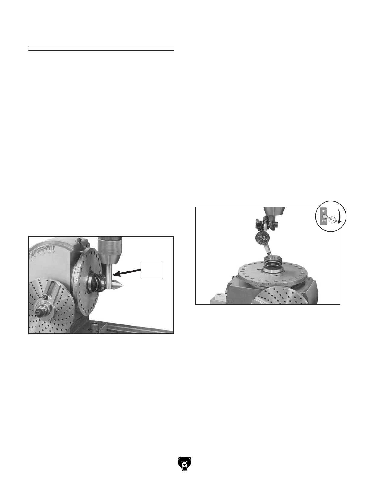
2. Mount the included dead center into the dividing head spindle and an edge finder into the
mill spindle, then move the mill table to position the edge finder in front of the center, as
shown in Figure 7.
7. Add half the diameter of the center and half
the diameter of the edge finder together,
then move the mill table in toward the mill an
additional distance equal to the calculated
number above.
Vertical Spindle
1. DISCONNECT MILL FROM POWER!
2. Make sure the dividing head is properly
aligned with the mill table and firmly secured
in position.
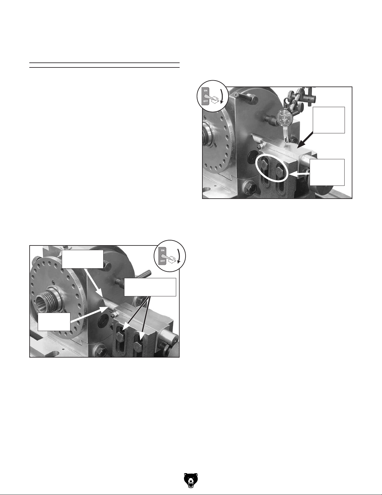
3. Mount a test indicator in the mill spindle and
position the indicator tip against the inside
wall of the dividing head spindle bore, as
shown in Figure 8.
Edge
Finder
Figure 7. Aligning the spindles using an edge
finder.
3. Set the mill for the slowest spindle speed,
then turn the mill ON.
4. Carefully and slowly move the table in-andout along the Y-axis until you find the edge of
the dividing head center.
5. Note the Y-axis position of the mill table.
Note: When recording the mill table position,
take into account the backlash that is usually
present in the leadscrew.
Figure 8. Indicating the spindle bore.
4. Slowly rotate the mill spindle by hand and
watch the test indicator dial.
Note: For best results, turn the spindle in only
one direction.
Tip: Use a mirror to view the indicator dial as
it turns away from you.
5. Slowly adjust the mill table to adjust for the
runout as shown on the indicator.
6. The spindles of the dividing head and mill
are centered with one another when the test
indicator shows zero runout when rotated a
full 360°.
-10 -
Model G1053/G1054 (Mfg. 1/09+)
Tailstock Center
Height
When supporting a workpiece between centers, it
is necessary to set the height of the tailstock center so that it is even and parallel with the center
line of the dividing head spindle. One method for
accomplishing this is listed below.
Tools Needed Qty
Wrench or Socket 14mm ................................... 1
To properly adjust the tailstock center height:
4. Loosen the hex nuts on the tailstock center
support lock bolts (see Figure 10), adjust the
tailstock center so that the tip is in the center
hole of the head and is approximately level,
then snug one of the hex nuts to hold it in
place.
Tailstock
Center
Support
1. DISCONNECT MILL FROM POWER!
2. Place the dividing head on the table and posi-
tion it so that the spindle faces toward the
operator.
3. Install the tailstock so that its center is aligned
with the center hole in the side of the dividing
head, as shown in Figure 9.
Center Hole
in Head
Center Support
Lock Bolts
Tailstock
Center
Center
Support
Lock Bolts
Figure 10. Indicating the tailstock center support.
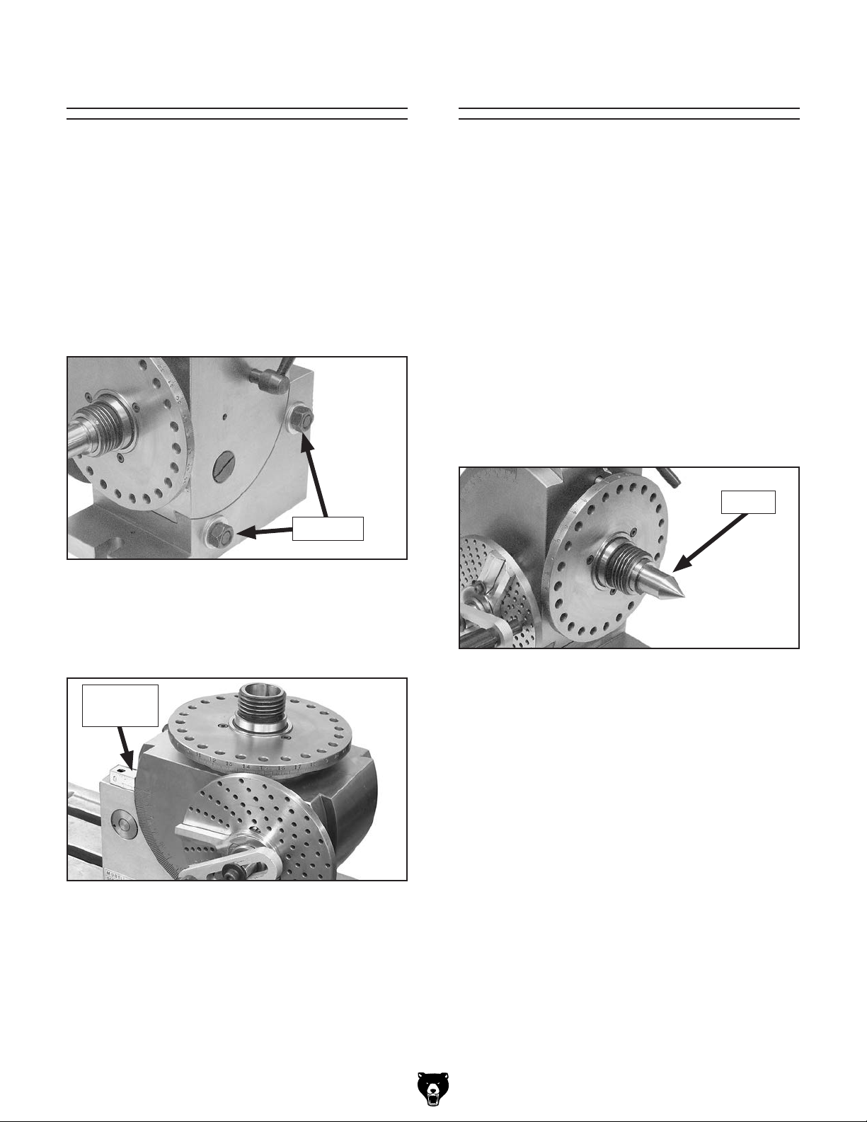
5. Mount a test indicator into the mill spindle
with the tip resting on the top of the tailstock
center support, as shown in Figure 10.
6. Move the mill table back-and-forth along its
X-axis so that the full length of the center
support is indicated.
7. Make adjustments to the height of the center
support until there is zero deviation indicated
along the full length of the center support,
then completely tighten the lock bolt hex
nuts.
8. Indicate the full length of the center support
again and make any necessary corrections.
Figure 9. Tailstock center contacting the center
hole of the dividing head.
Model G1053/G1054 (Mfg. 1/09+)
-11-

SECTION 3: OPERATIONS
To reduce the risk of
serious injury when
using this tool, read and
understand this entire
manual before beginning
any operations.
Damage to your eyes and lungs could result
from using this tool without proper protective gear. Always wear safety glasses and a
respirator when operating this tool.
Basic Controls
Use Figures 11–12 and the following descriptions
to become familiar with the basic controls of your
dividing head.
D
C
B
E
Loose hair, clothing, or
jewelry could get caught
in machinery and cause
serious personal injury.
Keep these items away
from moving parts at all
times to reduce this risk.
NOTICE
If you have never used this type of equipment before, WE STRONGLY RECOMMEND
that you read books, review industry trade
magazines, or get formal training before
beginning any projects. Regardless of the
content in this section, Grizzly Industrial
will not be held liable for accidents caused
by lack of training.
A
Figure 11. Basic controls, left side.
A. Hand Crank: Rotates the spindle when
turned. Pulling the knob out causes the index
pin to disengage from the dividing plate.
B. Dividing Plate: Provides 6 circles of holes
for indexing (1 of 3 plates).
C. Sector Arms: Sections the dividing plate into
a segment that allows you to keep track of
the fraction of rotation.
D. Head Tilt Scale: Shows the amount of spin-
dle tilt and is calibrated from -10° to +90° in
one degree increments.
E. Threaded Spindle: Provides threaded
mounting for the chuck backing plate or
other precision accessories. The threads are
1
⁄2"-8.
1
-12-
Model G1053/G1054 (Mfg. 1/09+)

F
G
Changing Dividing
Plates
H
The dividing plates can be changed when a specific hole count is required for indirect indexing.
Tools Needed Qty
J
I
Phillips Screwdriver #2 ...................................... 1
Hex Wrenches 3, 5mm ............................. 1 Each
To change the dividing plate:
Figure 12. Basic controls, right side.
F. Direct Indexing Plate: Provides 24 evenly
spaced holes for indexing 2, 3, 4, 6, 8, 12, or
24 locations.
G. Direct Indexing Lever: Engages the index-
ing pin with the direct indexing plate holes.
H. Spindle Lock: Locks the spindle in place to
ensure rigidity and accuracy.
I. Head Tilting Hex Nuts: When loosened,
allows the head to be tilted.
J. Mounting Base: Precision ground base with
slots for mounting to the mill table.
1. Remove the cap screw and flat washer that
secure the hand crank, then remove the
crank (see Figure 13).
Sector Arm Spring
Phillips
Head
Screw
Crank Handle
Figure 13. Dividing plate components.
2. Loosen the sector arm cap screw, then
remove the sector arm spring and the sector
arms.
Sector Arm
Cap Screw
Model G1053/G1054 (Mfg. 1/09+)
3. Replace the dividing plate, then re-install the
parts in the reverse order that you removed
them.
Note: Before storing or installing a dividing
plate, thoroughly clean it with mineral spirits,
then apply a thin coat of light machine oil to
the surfaces to prevent corrosion.
-13-
Tilting Spindle
Spindle Center
The spindle of your dividing head tilts from -10° to
+90° out of parallel from the bottom of the mounting base.
Tools Needed Qty
Wrench or Socket 19mm ................................... 1
To tilt the spindle:
1. Loosen the two tilt locking hex nuts on the
rear of the dividing head (see Figure 14).
Hex Nuts
Your dividing head includes a dead center for use
in the spindle. The spindle bore and the shank of
the center are a Brown & Sharpe taper #7 for the
Model G1053 and a #9 for the Model G1054.
To install the dead center:
1. Thoroughly clean the spindle bore and the
center shank. Inspect these surfaces for
scratches or nicks. If necessary, dress or
"stone" them (refer to Surface Care on Page
24 for detailed instructions).
2. Insert the center into the spindle bore to
within
center rapidly into the bore the rest of the way
to ensure the tapers lock (see Figure 16).
1
⁄2" of being fully seated, then thrust the
Center
Figure 14. Tilt locking hex nuts.
2. Tilt the spindle to the desired angle as dis-
played on the tilt scale, then re-tighten the
hex nuts (see Figure 15).
Tilt Scale
& Index
Figure 15. Spindle tilted vertical.
Note: It may be necessary to tap on the
hex nuts with a dead blow hammer to break
the locking bolts loose before the head will
move.
Figure 16. Dead center installed.
3. Test the taper lock by grasping the protruding
portion of the center and attempt to twist it out
of the bore.
— If the center comes out of the spindle bore,
repeat Steps 1–2 until it does not.
Removing Spindle Center
Tools Needed Qty
Brass or Aluminum Rod
Approx.
To remove the dead center:
1. Use a gloved hand or shop rags to hold the
5
⁄8" Diameter x 12"–16" Long ................ 1
center.
-14-
2. Insert the rod into the rear of the spindle bore
and tap the center until it releases.
Model G1053/G1054 (Mfg. 1/09+)

Center Dog
Chuck Backing Plate
When supporting the workpiece between centers,
it is necessary to use the center dog (sometimes
referred to as a drive bracket). The center dog that
is supplied with your dividing head is designed
to mount onto the included dead center and will
require the use of a bent-tail lathe dog (not provided) installed onto the workpiece.
To mount a workpiece between centers:
1. DISCONNECT MILL FROM POWER!
2. Loosen the middle hex nut on the center dog
until it clears the bore, slide it onto the dead
center, then re-tighten the hex bolt to secure
it in place, as shown in Figure 17.
A chuck backing plate is included with your dividing head for mounting a lathe chuck, as shown in
Figure 18.
Run True
Set Screw
Figure 18. Model G9856 6-jaw run true chuck
installed (Model G1054 only).
Follow these rules when mounting a chuck
onto your dividing head:
Figure 17. Workpiece installed between centers.
3. Install the lathe dog onto the workpiece with
the tail extending beyond the end of it.
4. Align the lathe dog tail with a side slot of
the center dog, then properly mount the
workpiece between the centers.
5. Tighten the two hex bolts on the center dog
so that they firmly hold the lathe dog tail.
Note: It may be necessary to alter the lathe
dog tail so that the hex bolts make contact
with two flat surfaces.
6. Make adjustments as necessary to ensure
that the workpiece does not rotate independently of the dead center.
• The backing plate must be mounted on a
lathe with a threaded mandrel, then faced
and shouldered.
• Make the new shoulder a "press fit" with the
chuck to maximize accuracy.
• Correctly drill holes into the backing plate to
accept the mounting of the chuck.
• For maximum accuracy when using the Model
G1054, a run true chuck should be used,
such as the Grizzly G9856 shown in Figure
18. This chuck has four set screws that allow
the center line of the chuck to be correctly
aligned with the center line of the dividing
head spindle.
Note: If you are using a run true chuck, a
press fit is not necessary.
Model G1053/G1054 (Mfg. 1/09+)
-15-

Setting Index Pin
The index pin on the end of the hand crank can
be repositioned to any of the six hole circles on
the dividing plate (see Figure 19). The index pin
is spring loaded so that it will stay engaged with
the current hole.
Numbered
Row
Hole Circle
(1 of 6)
Figure 19. Dividing plate.
2. Slightly loosen the crank cap screw, adjust
the crank arm on the shaft until the index pin
is aligned with the required hole circle on the
dividing plate, then re-tighten the cap screw.
Note: Because the index pin is spring loaded,
it will tend to push the crank arm out when the
cap screw is not tightened. As you re-tighten
the cap screw, push in on the crank arm so
that it stays flat against the shaft shoulder.
Using Dividing
Plates
Your dividing head includes three dividing plates,
each having six hole circles in the following patterns:
Plate Number of Holes Per Circle
Plate A ................................ 15, 16, 17, 18, 19, 20
Plate B ................................ 21, 23, 27, 29, 31, 33
Plate C ................................ 37, 39, 41, 43, 47, 49
Tools Needed Qty
Hex Wrench 5mm .............................................. 1
To set the index pin:
1. Pull the crank handle out to disengage the
index pin, then rotate the crank until it is
aligned with the numbered row on the dividing plate (see Figure 20).
All divisions from 1 to 50 can be made with one
of the three plates provided. However, not all of
the divisions from 51 to 100 are capable with your
dividing head, as noted with a "—" in the charts
on the next page.
The dividing charts on Page 17 are set up with
three rows and one column for each division.
Refer to the charts and the following descriptions
to understand the numbers in the rows.
D – Division: The number of stops required for
the machining operation.
H – Hole Circle: The number of the hole circle on
the dividing plate required for the division.
R – Rotations of the Crank Handle: The num-
ber of crank handle rotations required for the
division.
Figure 20. Adjusting the position of the crank
index pin.
-16 -
Model G1053/G1054 (Mfg. 1/09+)

indexing charts
Dividing Charts
D
H
R
D
H
R
D
H
R
D
H
R
D
H
T
1 2 3 4 5 6 7 8 9 10
Any 33 Any Any 33 49 Any 18 Any
11
20 13
⁄33 10 8 6 22⁄33 5 35⁄49 5 4 8⁄18 4
11 12 13 14 15 16 17 18 19 20
33 33 39 49 33 20 17 18 19 Any
21
⁄33 3 11⁄33 3 3⁄39 2 42⁄49 2 22⁄33 2 10⁄20 2 6⁄17 2 4⁄18 2 2⁄19 2
3
21 22 23 24 25 26 27 28 29 30
21 33 23 33 20 39 27 49 29 33
19
⁄21 1 27⁄33 1 17⁄23 1 22⁄33 1 12⁄20 1 21⁄39 1 13⁄27 1 21⁄49 1 11⁄29 1 11⁄33
1
31 32 33 34 35 36 37 38 39 40
31 20 33 17 49 18 37 19 39 Any
1
9
⁄31
1
5
⁄20
1
7
⁄33
1
3
⁄17
1
7
⁄49
1
2
⁄18
1
3
⁄37
1
1
⁄19
1
1
⁄39
41 42 43 44 45 46 47 48 49 50
41 21 43 33 18 23 47 18 49 20
40
⁄41
20
⁄21
40
⁄43
30
⁄33
16
⁄18
20
⁄23
40
⁄47
15
⁄18
40
⁄49
1
16
⁄20
D
H
R
D
H
R
D
H
R
D
H
R
D
H
R
51 52 53 54 55 56 57 58 59 60
— 39 — 27 33 49 — 29 — 33
30
⁄39
20
⁄27
24
⁄33
35
⁄49
20
⁄29
22
⁄33
61 62 63 64 65 66 67 68 69 70
— 31 — 16 39 33 — 17 — 49
20
⁄31
10
⁄16
24
⁄39
20
⁄33
10
⁄17
28
⁄49
71 72 73 74 75 76 77 78 79 80
— 18 — 37 15 19 — 39 — 20
10
⁄18
20
⁄37
8
⁄15
10
⁄19
20
⁄39
10
⁄20
81 82 83 84 85 86 87 88 89 90
— 41 — 21 17 43 — 33 — 18
20
⁄41
10
⁄21
8
⁄17
20
⁄43
15
⁄33
8
⁄18
91 92 93 94 95 96 97 98 99 100
— 23 — 47 19 — — 49 — 20
10
⁄23
20
⁄47
8
⁄19
20
⁄49
8
⁄20
Legend:
D – Divisions
H – Hole Circle
R – Rotations of the Crank Handle
Model G1053/G1054 (Mfg. 1/09+)
-17-

Example
To better understand how to properly use the
dividing plates, perform the instructions in the
example below.
In this example, you will set up the dividing
head for 18 divisions:
6. Position the left sector arm up against the
index pin.
7. Move the right sector arm clockwise so that
there are four holes showing in the 18 hole
circle between the arms, as shown in Figure
22.
1. Locate division 18 in the charts on the pre-
vious page, then note the number directly
below it, which is the required hole circle. In
this case, the hole circle is 18.
2. Install the dividing plate with the 18 hole
circle on the dividing plate, as instructed in
the Changing Dividing Plates section on
Page 13.
3. Loosen the sector arm cap screw, spread the
sector arms apart so that you can position
the index pin of the crank handle between
the sector arms and in a hole of the 18 hole
circle, as shown in Figure 21.
Note: Do not count the hole that the index pin
is in.
Figure 22. Sector arms correctly spread apart
four holes on the 18 hole circle.
8. Tighten the sector arm cap screw to secure
the arms in place and to preserve the correct
4-hole spacing.
Figure 21. Index pin between the sector arms
and seated in the 18 hole circle.
4. Make sure the crank cap screw is fully tightened to firmly secure the crank on the shaft.
5. Look at the division 18 column of the chart
again and note the number in the third row
4
below it. In this case the number is 2
⁄18,
which means the crank handle will be rotated
4
two full turns and
⁄18, or 4 holes, of the third
rotation for each machining cycle after the
first one.
9. Eliminate the backlash in the crank by pulling
the crank handle out to disengage the index
1
pin, rotating the crank
⁄2 counterclockwise
turn, then turning it clockwise and engaging
the index pin with the hole it was in before.
Note: To ensure accurate indexing, it is
imperative that the crank index pin does not
make contact with the sector arms as you
rotate the crank so that the sector arms do
not move from their correct locations.
-18-
Model G1053/G1054 (Mfg. 1/09+)

10. Lock the spindle in place and perform the
machining operation.
11. Without moving the sector arms, pull the
crank handle out to disengage the index pin
and carefully rotate the crank two full turns
clockwise back to the position it started in.
Divisions Beyond 100
In the event that divisions beyond 100 are required,
you can usually find the correct hole circle number
to use by dividing the number of divisions by the
number of the hole circles available on the dividing plates until the answer is a whole number
(without a fraction or decimal).
12. Continue to rotate the crank clockwise until
you can engage the index pin into the hole
that is next to the right sector arm. You have
now rotated the crank handle the required
4
⁄18 turns, as shown in Figure 23.
2
Note: If you move the crank index pin beyond
the final hole, it is crucial to the operation that
you eliminate the crank backlash again, as
explained in Step 9.
Figure 23. Crank position after 2 4⁄18 rotations.
13. While keeping the sector arm cap screw tight,
rotate the sector arms clockwise so that the
left sector arm is up against the crank index
pin and the right arm has moved an additional
4 holes.
Note: If the sector arm cap screw is loos-
ened, the arms will move independently from
one another and the 4-hole spacing will be
changed.
For example, for a division of 115, dividing the
number 23 into 115 gives the answer of 5, a whole
number. This means that the dividing plate with
the 23 hole circle can be used.
The rotation of the crank for each division will
always be less than one full turn for divisions
beyond 40. The amount of holes on the required
hole circle that the crank must be moved can be
found with the following formula:
R = (H x 40) / D
where R is the number of holes between the sector arms, H is the number of the required hole
circle, 40 is a constant that represents the number
of full crank rotations necessary to complete one
revolution of the spindle, and D is the number of
divisions required for the operation.
To continue the example given above, if the number of divisions needed is 115 and the number of
the dividing plate hole circle is 23, then the number of holes that the sector arms must be separated per division is 8, as calculated below:
R = (23 x 40) / 115
R = 920 / 115
R = 8
Note: As in the divisions between 50 and 100,
not all divisions beyond 100 are possible with your
dividing head.
14. Repeat Steps 9–13 until the dividing spindle
and workpiece have made one full revolution.
Model G1053/G1054 (Mfg. 1/09+)
-19 -

Use the following tips to help ensure a trouble-free dividing head operation:
Disengaging Worm
• Because the scale on the direct indexing
plate mounted on the dividing head spindle
is oriented clockwise, always rotate the crank
clockwise to make it easier to keep track of
the spindle orientation during the operation.
• Take the time to create a quick-reference
chart when divisions are complex. Using this
chart to compare with the degree scale and
check off as you change locations will reduce
unnecessary mistakes.
• As in most operations, it is a good idea to
perform a test-run before actually making the
cuts, especially before machining an expensive part. Test your dividing setup by running
the complete progression of settings and
turns without actually machining the part.
For example, when performing a test-run for
the previous example, the spindle should
return to its original position after running
the 18 positions. This can be verified by noting the location of the spindle on the degree
scale before and after the test-run. Also, you
can score the part at each division stop to
make sure the cuts will be in the required
locations, as shown in Figure 24.
The worm gear and wheel drive the spindle when
the crank is rotated and these gears are engaged.
They can be disengaged to rotate the spindle by
hand for quick direct indexing.
Tools Needed Qty
Hex Wrenches 3, 4, 5mm ......................... 1 Each
Phillips Screwdriver #2 ...................................... 1
To disengage the worm gear and wheel:
1. Remove the crank handle, sector spring, sec-
tor arms, and dividing plate.
2. Loosen the two cap screws that secure the
worm gear hub, rotate it counterclockwise
until you can turn the spindle by hand, then
re-tighten the cap screws (see Figure 25).
Worm Gear Hub
Figure 24. Scoring the part during a test run.
-20-
Figure 25. Disengaging worm gear and wheel.
To re-engage the worm gear and wheel:
1. Rotate the worm gear hub clockwise until you
feel resistance, then tighten the cap screws.
2. Check the rotation of the spindle with the
crank before reassembling the rest of the
parts. If necessary, re-adjust the rotation of
the worm gear hub so that the crank rotates
freely without excess backlash.
Model G1053/G1054 (Mfg. 1/09+)

Cutting Angles
The dividing head can be used for cutting a specific angle or producing a series of angles, such
as in faceting. Perform the example below to learn
how to use your dividing head for angled cuts.
To produce a hex shape (6-sided) with the
dividing head:
1. Disengage the worm gear and wheel so that
the spindle can be rotated by hand.
2. Rotate the spindle by hand until the zero
point of the degree scale is aligned with the
pointer, as shown in Figure 26.
Note: In the next step, keep in mind that the
direct indexing plate mounted on the spindle
has 24 holes, which is evenly divisible by
6. Each index stop will require that 4 holes
pass by the index pin—i.e., the index pin will
engage the 5
was.
3. Use the direct indexing lever to engage the
pin into the plate hole.
Note: If necessary, rock the plate by hand
until the pin engages the hole, then loosen
the pointer cap screw, adjust it to the zero
mark on the degree scale, and re-tighten the
cap screw to secure it in place.
4. Properly mount the workpiece onto the dividing head.
th
hole from where it originally
Pointer
Degree
Scale
Figure 26. Direct indexing plate.
Direct
Indexing Plate
5. Lock the spindle and machine the part.
6. Unlock the spindle, use the lever to disen-
gage the pin, rotate the plate clockwise by
hand until the pin is aligned with the 5
from where it originally was, then re-engage
the pin with the plate.
Note: The pointer will be aligned at the 60°
mark on the degree scale.
7. Repeat Steps 5–6 until the spindle and
workpiece have completed one full revolution.
th
hole
Model G1053/G1054 (Mfg. 1/09+)
-21-

ACCESSORIES
SECTION 4: ACCESSORIES
G9610—Test Indicator
0.03" Range/0.001" Resolution
G9611—Test Indicator
0.008" Range/0.0001" Resolution
G9612—Test Indicator
0.030" Range/0.0005" Resolution
These test indicators have an easy to read dial
and a pivoting stylus that moves at right angles to
the dial face.
1
G1075—52-PC. Clamping Kit
G1076—52-PC. Clamping Kit
⁄2" T-Nut
5
⁄8" T-Nut
This clamping kit includes 24 studs, 6 step block
pairs, 6 T-nuts, 6 flange nuts, 4 coupling nuts, and
6 end hold-downs. The rack is slotted so it can be
mounted close to the machine for easy access.
Figure 27. Test Indicator.
H2939—4 Piece Edge Finder Set
Four different styles to cover any setup problem!
Set includes one each: a
3
point, a combination
a 0.200" shoulder, a
⁄8" diameter with a point and
1
shoulder, and a combination
3
⁄8" diameter with a
⁄2 " diameter with a 0.200"
1
⁄2 " diameter with a
0.200" shoulder and a 0.500" shoulder.
Figure 29. 52-PC. Clamping Kit.
G9856—6-Jaw Precision Run True Chuck
When used with your dividing head, this chuck
offers maximum holding power on delicate parts
and absolute positioning using the 4 adjustment
screws.
Figure 30. G9856 6-Jaw Chuck.
Figure 28. H2939 4-Pc. Edge Finder Set.
-22-
Model G1053/G1054 (Mfg. 1/09+)

SECTION 5: MAINTENANCE
Schedule
For optimum performance from your dividing
head, follow this maintenance schedule and refer
to any specific instructions given in this section.
Every 8 Hours of Use:
• Clean and lubricate the tool.
• Dress the surfaces of the tool (Page 24).
• Check/resolve any unsafe condition.
Every 160 Hours of Use:
• Disassemble, clean, and lubricate the worm
gear and wheel (Page 24).
Cleaning
To ensure smooth operation and long life of your
dividing head, it is essential that it is cleaned after
every use and a thin coat of light machine oil is
applied to the surfaces to prevent corrosion.
DO NOT use compressed air to clean your dividing head. This could force chips and swarf to
become lodged between the moving parts and
reduce the life and accuracy of the tool. Instead,
use a stiff-bristled brush to remove the chips and
swarf, then wipe down the surfaces with a clean
shop rag.
Lubrication
Ball Oiler & Oil Port
Wipe off the ball oiler on the head shown in
Figure 31, then use the tip of an oil can to add
one squirt of 30W non-detergent oil to the oiler.
Ball Oiler
Figure 31. Ball oiler on the head.
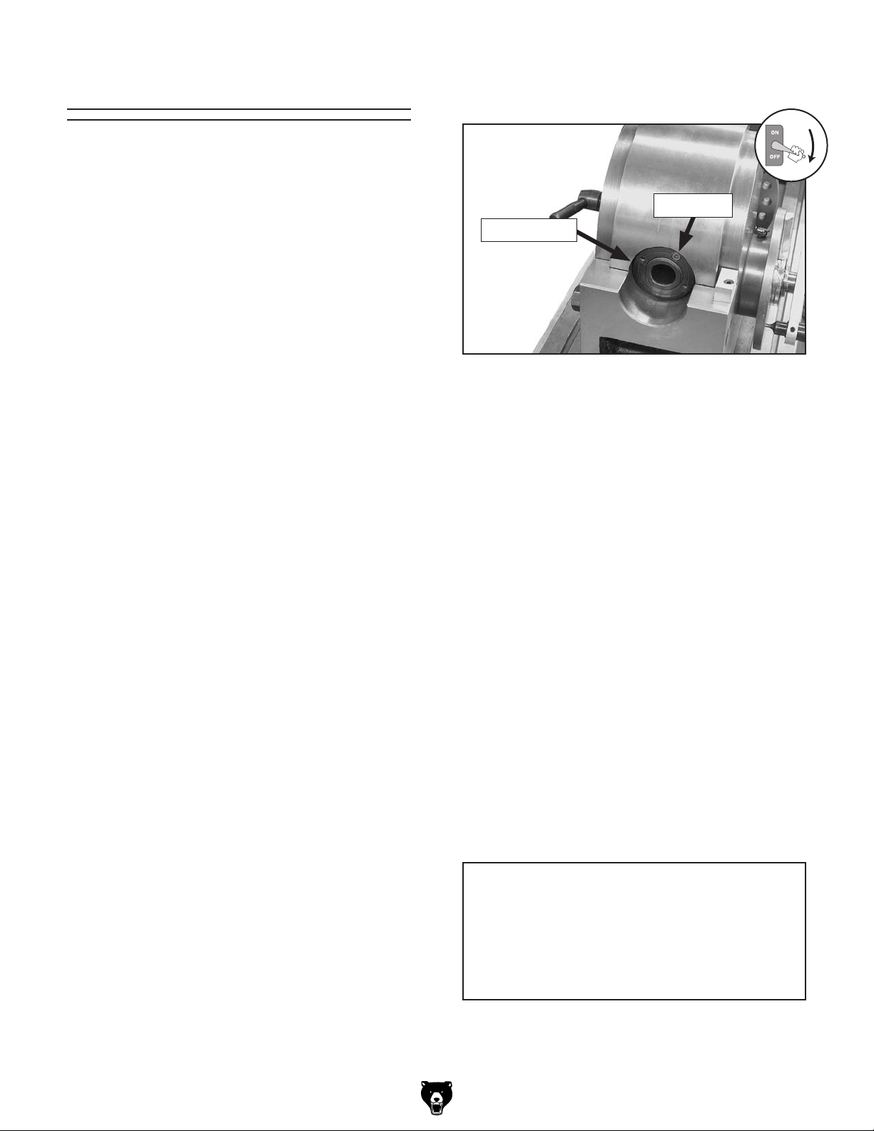
Open the lid of the oil port on the worm gear hub
shown in Figure 32, then add one squirt of 30W
non-detergent oil to the port. Make sure to close
the lid to keep debris out.
Oil Port
Model G1053/G1054 (Mfg. 1/09+)
Figure 32. Worm gear oil port.
-23-

Worm Gear & Wheel
Tools Needed Qty
Hex Wrenches 3, 4, 5mm ......................... 1 Each
Phillips Screwdriver #2 ...................................... 1
To lubricate the worm gear and wheel:
1. Remove the crank handle, sector spring, sec-
tor arms, and dividing plate.
2. Remove the two cap screws that secure the
worm gear hub, then remove the hub from
the worm gear shaft, as shown in Figure 33.
Surface Care
Nicks, dings, and scratches on the surfaces of
the dividing head and mill table can have an
adverse effect on accuracy and may damage the
workpiece or mill table.
Prior to use, dress or "stone" these surfaces with
a fine sharpening stone until they are smooth. A
few strokes of the stone on the mill table surface
and the machined surfaces of the dividing head
will help to ensure machining accuracy.
Worm
Wheel
Worm Gear
Worm Gear Hub
Figure 33. Worm gear removed to expose the
worm wheel.
3. Use a stiff-bristled brush, shop rags, and
mineral spirits to clean away the old grease
and grime. When dry, apply a light coat of
medium bearing grease, then re-install the
parts.
Make sure to thoroughly wipe these surfaces
clean to remove any dust generated from the process, then re-apply a thin coat of light machine oil
to prevent corrosion.
-24-
Model G1053/G1054 (Mfg. 1/09+)
Bearing Preload
The spindle in the dividing head is mounted
with tapered roller bearings. The preload on
these bearings was set at the factory and should
never need adjusting. However, if you experience
excess play in the spindle, you can adjust the
spindle bearing preload.
Testing Spindle Play
1. DISCONNECT MILL FROM POWER!
2. Firmly mount the dividing head to the mill
table.
4. Loosen the set screw on the spanner nut
shown in Figure 34.
Set Screw
Spanner Nut
Figure 34. Spanner nut and set screw.
3. Mount a test indicator in the mill spindle and
rest the indicator tip on the top of the spindle
nose.
4. While watching the indicator dial, attempt to
lift the spindle up.
— If the test indicator shows zero deviation
as you attempt to lift the spindle up, there
is no spindle play and the bearing preload
is sufficient.
— If the indicator shows a deviation when you
attempt to lift the spindle up, there is not
enough bearing preload. Continue to the
next subsection to adjust the preload.
Adjusting Bearing Preload
Tools Needed Qty
Hex Wrench 3mm .............................................. 1
Hammer & Punch ..................................... 1 Each
Dead Blow Hammer .......................................... 1
To adjust the bearing preload:
5. Rotate the spanner nut counterclockwise one
full turn, then tap on it with the dead blow
hammer to release the bearing preload.
6. Position a test indicator so that the indicator
tip is touching the front end of the spindle.
7. While watching the test indicator, rotate the
spanner nut clockwise until the indicator dial
stops moving.
Note: By accurately performing this step, you
have reached the zero preload point, which
means that all of the slack has been taken up
between the bearings, seats, and spindle.
8. Tighten the spanner nut clockwise an addi-
9. Test the spindle play. If necessary, repeat
1
tional
er amount of bearing preload, then re-tighten
the set screw.
this procedure until you have achieved the
proper amount of bearing preload.
⁄16 of its circumference to set the prop-
1. DISCONNECT MILL FROM POWER!
2. Firmly mount the dividing head to the mill
table.
3. Use the spindle lock lever to hold the spindle
in place.
Model G1053/G1054 (Mfg. 1/09+)
NOTICE
Spindle bearing life will be greatly reduced
if the preload is either too loose or too tight.
Disengage the worm gear and wheel and
rotate the spindle by hand to make sure it
turns easily without any play.
-25-
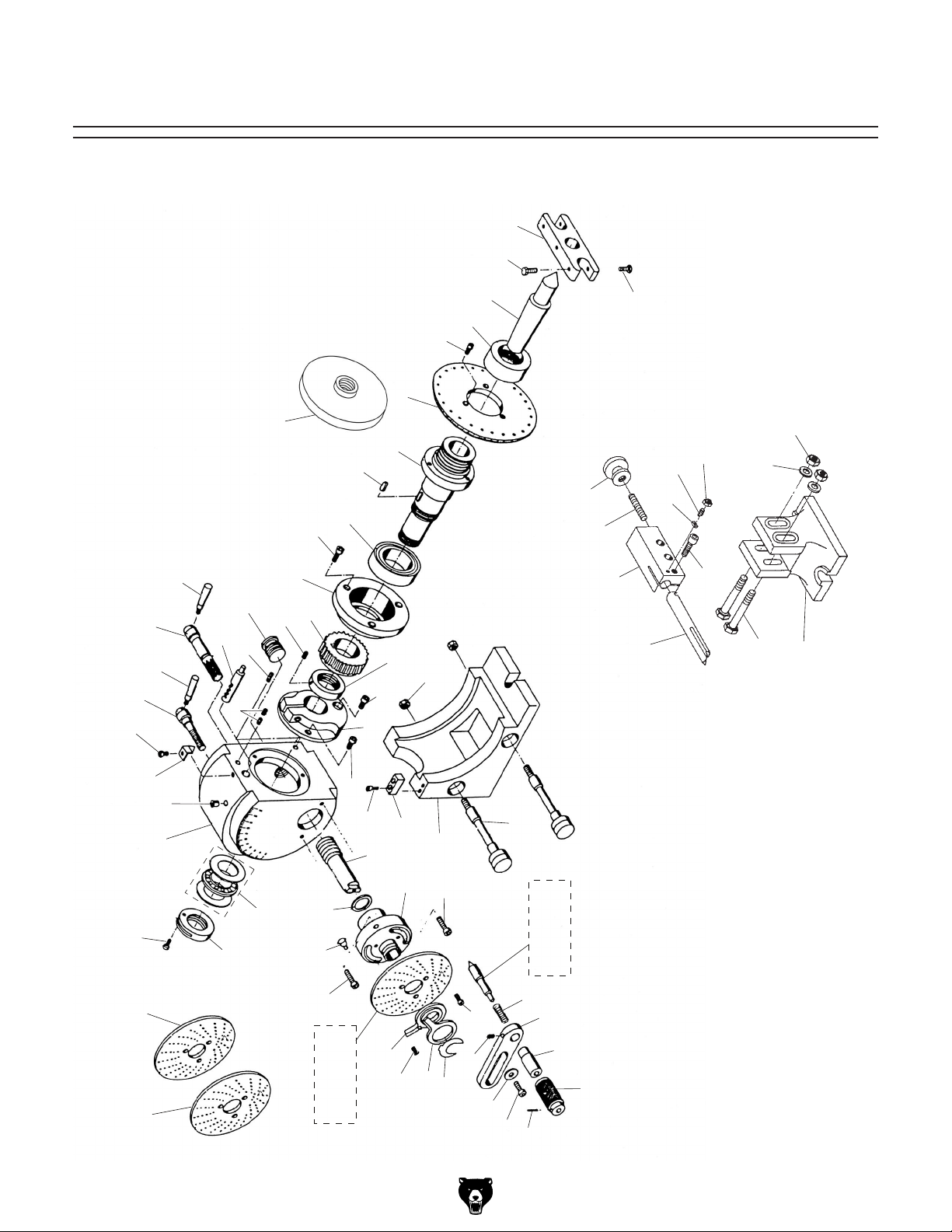
SECTION 6: PARTS
G1053/G1054 Main Breakdown
1
2
22
20
18
17
17
19
13
15
16
113
13
10
11
73
3
4
5
6
7
8
9
12
56
36
54
107
106
102
2
103
105
104
108
109
111
112
110
101
-26-
27
35A
21
24
35B
23
26
25
53
52
40
39
38
36
35 (G1054)
35C (G1053)
34
22
30
29
48
45
28
46 (G1054)
46A (G1053)
44
43
42
51
50
37
36
33
31
32
4
Model G1053/G1054 (Mfg. 1/09+)

G1053 Parts List
REF PART # DESCRIPTION REF PART # DESCRIPTION
1 P1053001 CENTER DOG 35B P1053035B DIVIDING PLATE 21-33 HOLE
2 PB03M HEX BOLT M8-1.25 X 16 35C P1053035C DIVIDING PLATE 37-49 HOLE
3 P1053003 TAPERED BUSHING 36 PCAP24M CAP SCREW M5-.8 X 16
4 PFH19M FLAT HD SCR M4-.7 X 10 37 P1053037 MOUNTING BRACKET
5 P1053005 DIRECT INDEXING PLATE 38 P1053038 OIL FITTING
6 P1053006 SPINDLE 39 P1053039 SPACER
7 PK08M KEY 5 X 5 X 16 40 P1053040 WORM SHAFT GEAR
8 P32007 TAPERED BEARING 32007 42 P1053046 OUTER HANDLE
9 PCAP23M CAP SCREW M4-.7 X 12 43 P1053046 INNER HANDLE
10 P1053010 FRONT BEARING SEAT 44 P1053044 HANDLE BRACKET
11 P1053011 WORM GEAR 45 P1053046 COMPRESSION SPRING
12 P1053012 RETAINING NUT M30-1.5 46A P1053046A INDEX NEEDLE W/42, 43, 44, 45
13 PSS34M SET SCREW M5-.8 X 16 48 P1053048 THREADED CLAMP SHAFT
15 P1053015 PLUG 50 P1053050 BASE
16 PSS34M SET SCREW M5-.8 X 16 51 P1053051 SCALE INDEX
17 P1053017 HANDLE 52 PCAP16M CAP SCREW M4-.7 X 16
18 P1053018 GEARED HANDLE SHAFT 53 PCAP33M CAP SCREW M5-.8 X 12
19 P1053019 GEARED INDEXING PIN 54 P1053054 LASHING RING
20 P1053020 LOCK SHAFT 56 PN31M HEX NUT M12-1.5
21 P1053021 POINTER 73 P1053073 DEAD CENTER B&S#7
22 PS09M PHLP HD SCR M5-.8 X 10 101 P1053101 TAILSTOCK BASE
23 P1053023 OIL FITTING 1/4" 102 P1053102 CENTER BASE
24 P1053024 MAIN CASTING 103 P1053103 TAILSTOCK CENTER
25 P1053025 NEEDLE THRUST BEARING 25X42X4 104 PK06M KEY 5 X 5 X 10
26 P1053026 SPLIT RETAINING NUT M25-1.5 105 PSS11M ECCENTRIC SET SCREW M6-1 X 16
27 PCAP18M CAP SCREW M4-.7 X 8 106 P1053106 THREADED SHAFT
28 PRP02 ROLL PIN 1/8 X 3/4 107 P1053107 KNURLED KNOB
29 PCAP26M CAP SCREW M6-1 X 12 108 PN01M HEX NUT M6-1
30 PW03M FLAT WASHER 6MM 109 PCAP72M CAP SCREW M10-1.5 X 30
31 PSS07M SET SCREW M5-.8 X 5 110 PN02M HEX NUT M10-1.5
32 P1053032 RETAINING CLIP 111 PW04M FLAT WASHER 10MM
33 P1053033 FRONT SECTOR ARM 112 PB13M HEX BOLT M10-1.5 X 80
34 P1053034 REAR SECTOR ARM 113 P1053113 CHUCK BACKING PLATE
35A P1053035A DIVIDING PLATE 15-20 HOLE
Model G1053/G1054 (Mfg. 1/09+)
-27-

G1054 Parts List
REF PART # DESCRIPTION REF PART # DESCRIPTION
1 P1054001 CENTER DOG 35A P1054035A DIVIDING PLATE 15-20
2 PCAP24M CAP SCREW M5-.8 X 16 35B P1054035B DIVIDING PLATE 21-33
3 P1054003 TAPERED BUSHING 36 PCAP15M CAP SCREW M5-.8 X 20
4 PFH19M FLAT HD SCR M4-.7 X 10 37 P1054037 MOUNTING BRACKET
5 P1054005 DIRECT INDEXING PLATE 38 P1054038 OIL FITTING
6 P1054006 SPINDLE 39 P1054039 SPACER
7 PK08M KEY 5 X 5 X 16 40 P1054040 WORM SHAFT GEAR
8 P1054008 TAPERED BEARING 32009 42 P1054042 OUTER HANDLE
9 PCAP33M CAP SCREW M5-.8 X 12 43 P1054043 INNER HANDLE
10 P1054010 FRONT BEARING SEAT 44 P1054044 HANDLE BRACKET
11 P1054011 WORM GEAR 45 P1054045 COMPRESSION SPRING 10X12X45
12 P1054012 RETAINING NUT M38-1.5 46 P1054046 INDEX NEEDLE
13 PSS34M SET SCREW M5-.8 X 16 48 P1054048 THREADED CLAMP SHAFT
15 P1054015 PLUG 50 P1054050 BASE
16 PSS34M SET SCREW M5-.8 X 16 51 P1054051 SCALE INDEX
17 P1054017 HANDLE 52 PCAP16M CAP SCREW M4-.7 X 16
18 P1054018 GEARED HANDLE SHAFT 53 PCAP33M CAP SCREW M5-.8 X 12
19 P1054019 GEARED INDEXING PIN 54 P1054054 LASHING RING
20 P1054020 LOCK SHAFT 56 PN09M HEX NUT M12-1.75
21 P1054021 POINTER 73 P1054073 DEAD CENTER B&S#9
22 PS09M PHLP HD SCR M5-.8 X 10 101 P1054101 TAILSTOCK BASE
23 P1054023 OIL FITTING 1/4" 102 P1054102 CENTER BASE
24 P1054024 MAIN CASTING 103 P1054103 TAILSTOCK CENTER
25 P1054025 NEEDLE THRUST BEARING 30X47X4 104 P1054104 SPECIAL KEY 3/16 X 3/16 X 3/8
26 P1054026 SPLIT RETAINING NUT M30-1.5 105 P1054105 ECCENTRIC SET SCREW M6-1 X 16
27 PS07M PHLP HD SCR M4-.7 X 8 106 P1054106 THREADED SHAFT
28 PRP02 ROLL PIN 1/8 X 3/4 107 P1054107 KNURLED KNOB
29 PCAP33M CAP SCREW M5-.8 X 12 108 PN01M HEX NUT M6-1
30 PW02M FLAT WASHER 5MM 109 PCAP72M CAP SCREW M10-1.5 X 30
31 PSS07M SET SCREW M5-.8 X 5 110 PN02M HEX NUT M10-1.5
32 P1054032 RETAINING CLIP 111 PW04M FLAT WASHER 10MM
33 P1054033 FRONT SECTOR ARM 112 PB13M HEX BOLT M10-1.5 X 80
34 P1053034 REAR SECTOR ARM 113 P1054113 CHUCK BACKING PLATE
35 P1054035 DIVIDING PLATE 37-49
-28-
Model G1053/G1054 (Mfg. 1/09+)

Notes


WARRANTY CARD
Name _____________________________________________________________________________
Street _____________________________________________________________________________
City _______________________ State _________________________ Zip _____________________
Phone # ____________________ Email _________________________________________________
Model # ____________________ Order # _______________________ Serial # __________________
The following information is given on a voluntary basis. It will be used for marketing purposes to help us develop
better products and services. Of course, all information is strictly confidential.
1. How did you learn about us?
____ Advertisement ____ Friend ____ Catalog
____ Card Deck ____ Website ____ Other:
2. Which of the following magazines do you subscribe to?
____ Cabinetmaker & FDM
____ Family Handyman
____ Hand Loader
____ Handy
____ Home Shop Machinist
____ Journal of Light Cont.
____ Live Steam
____ Model Airplane News
____ Old House Journal
____ Popular Mechanics
3. What is your annual household income?
____ $20,000-$29,000 ____ $30,000-$39,000 ____ $40,000-$49,000
____ $50,000-$59,000 ____ $60,000-$69,000 ____ $70,000+
CUT ALONG DOTTED LINE
4. What is your age group?
____ 20-29 ____ 30-39 ____ 40-49
____ 50-59 ____ 60-69 ____ 70+
5. How long have you been a woodworker/metalworker?
____ 0-2 Years ____ 2-8 Years ____ 8-20 Years ____ 20+ Years
6. How many of your machines or tools are Grizzly?
____ 0-2 ____ 3-5 ____ 6-9 ____10+
____ Popular Science
____ Popular Woodworking
____ Precision Shooter
____ Projects in Metal
____ RC Modeler
____ Rie
____ Shop Notes
____ Shotgun News
____ Today’s Homeowner
____ Wood
____ Wooden Boat
____ Woodshop News
____ Woodsmith
____ Woodwork
____ Woodworker West
____ Woodworker’s Journal
____ Other:
7. Do you think your machine represents a good value? _____ Yes _____No
8. Would you recommend Grizzly Industrial to a friend? _____Yes _____No
9. Would you allow us to use your name as a reference for Grizzly customers in your area?
Note: We never use names more than 3 times. _____ Yes _____No
10. Comments: _____________________________________________________________________
_________________________________________________________________________________
_________________________________________________________________________________
_________________________________________________________________________________

FOLD ALONG DOTTED LINE
FOLD ALONG DOTTED LINE
Place
Stamp
Here
GRIZZLY INDUSTRIAL, INC.
P.O. BOX 2069
BELLINGHAM, WA 98227-2069
Send a Grizzly Catalog to a friend:
Name_______________________________
Street_______________________________
City______________State______Zip______
TAPE ALONG EDGES--PLEASE DO NOT STAPLE

WARRANTY AND RETURNS
We shall in no event be liable for death, injuries to persons or property or for incidental, contingent, special,
WARRANTY AND RETURNS
Grizzly Industrial, Inc. warrants every product it sells for a period of 1 year to the original purchaser from
the date of purchase. This warranty does not apply to defects due directly or indirectly to misuse, abuse,
negligence, accidents, repairs or alterations or lack of maintenance. This is Grizzly’s sole written warranty
and any and all warranties that may be implied by law, including any merchantability or fitness, for any particular purpose, are hereby limited to the duration of this written warranty. We do not warrant or represent
that the merchandise complies with the provisions of any law or acts unless the manufacturer so warrants.
In no event shall Grizzly’s liability under this warranty exceed the purchase price paid for the product and
any legal actions brought against Grizzly shall be tried in the State of Washington, County of Whatcom.
or consequential damages arising from the use of our products.
To take advantage of this warranty, contact us by mail or phone and give us all the details. We will then
issue you a “Return Number,’’ which must be clearly posted on the outside as well as the inside of the
carton. We will not accept any item back without this number. Proof of purchase must accompany the
merchandise.
The manufacturers reserve the right to change specifications at any time because they constantly strive to
achieve better quality equipment. We make every effort to ensure that our products meet high quality and
durability standards and we hope you never need to use this warranty.
Please feel free to write or call us if you have any questions about the machine or the manual.
Thank you again for your business and continued support. We hope to serve you again soon.

 Loading...