

Page 1

COMBINATION SANDER
MODEL G1013
INSTRUCTION MANUAL
COPYRIGHT © 1991 BY GRIZZLY INDUSTRIAL, INC.
WARNING: NO PORTION OF THIS MANUAL MAY BE REPRODUCED IN ANY SHAPE
OR FORM WITHOUT THE WRITTEN APPROVAL OF GRIZZLY INDUSTRIAL, INC.
REVISED FEBRUARY, 2002. PRINTED IN TAIWAN
ONLINE MANUAL DISCLAIMER
THE INFORMATION IN THIS MANUAL REPRESENTS THE CONFIGURATION OF THE MACHINE AS IT IS CURRENTLY BEING SHIPPED. THE
MACHINE CONFIGURATION CAN CHANGE AS PRODUCT IMPROVEMENTS ARE INCORPORATED. IF YOU OWN AN EARLIER VERSION OF THE
MACHINE, THIS MANUAL MAY NOT EXACTLY DEPICT YOUR MACHINE. CONTACT CUSTOMER SERVICE IF YOU HAVE ANY QUESTIONS
ABOUT DIFFERENCES. PREVIOUS VERSIONS ARE NOT AVAILABLE ONLINE.
Page 2

WARNING
Some dust created by power sanding, sawing, grinding, drilling, and other construction activities contains
chemicals known to the State of California to cause
cancer, birth defects or other reproductive harm.
Some examples of these chemicals are:
• Lead from lead-based paints.
• Crystalline silica from bricks, cement, and
other masonry products.
• Arsenic and chromium from chemically treated
lumber.
Your risk from these exposures varies, depending on
how often you do this type of work. To reduce your
exposure to these chemicals: work in a well ventilated
area, and work with approved safety equipment, such
as those dust masks that are specially designed to filter out microscopic particles.
Page 3

Table Of Contents
PAGE
1. SAFETY
SAFETY INSTRUCTIONS FOR POWER TOOLS ................................................2-3
ADDITIONAL SAFETY INSTRUCTIONS FOR SANDERS ......................................4
2. CIRCUIT REQUIREMENTS
110V OPERATION ....................................................................................................5
FUSING ....................................................................................................................5
EXTENSION CORDS ................................................................................................5
GROUNDING ............................................................................................................5
3. INTRODUCTION
COMMENTARY ........................................................................................................6
UNPACKING..............................................................................................................7
PARTS INVENTORY ................................................................................................8
CLEAN UP ................................................................................................................9
SITE CONSIDERATIONS ........................................................................................9
4. ASSEMBLY
OVERVIEW..............................................................................................................10
ASSEMBLY PROCESS......................................................................................10-13
5. ADJUSTMENTS
BELT TRACKING ....................................................................................................14
BELT TABLE TILT ..................................................................................................15
BELT REPLACEMENT............................................................................................15
DISC TABLE TILT ..................................................................................................16
DISC REPLACEMENT ............................................................................................16
6. OPERATIONS
TEST RUN ..............................................................................................................17
GENERAL SANDING ..............................................................................................18
CONTOUR SANDING ............................................................................................18
INSIDE SANDING ..................................................................................................19
SHARPENING ........................................................................................................19
7. MAINTENANCE
GENERAL................................................................................................................20
TABLE......................................................................................................................20
LUBRICATION ........................................................................................................20
MAINTENANCE NOTES ........................................................................................21
8. CLOSURE ....................................................................................................................22
MACHINE DATA......................................................................................................................23
PARTS LIST AND DIAGRAM ............................................................................................24-25
WARRANTY AND RETURNS..................................................................................................26
Page 4
-2- G1013 Combination Sander
Safety Instructions For Power Tools
SECTION 1: SAFETY
5. KEEP CHILDREN AND VISITORS
AWAY. All children and visitors should be
kept a safe distance from work area.
6. MAKE WORKSHOP CHILD PROOF with
padlocks, master switches, or by removing
starter keys.
7. NEVER FORCE TOOL. It will do the job
better and safer at the rate for which it was
designed.
8. USE RIGHT TOOL. Do not force tool or
attachment to do a job for which it was not
designed.
1. KEEP GUARDS IN PLACE and in working
order.
2. REMOVE ADJUSTING KEYS AND
WRENCHES. Form habit of checking to
see that keys and adjusting wrenches are
removed from tool before turning on.
3. KEEP WORK AREA CLEAN. Cluttered
areas and benches invite accidents.
4. NEVER USE IN DANGEROUS ENVIRONMENT. Do not use power tools in
damp or wet locations, or where any flammable or noxious fumes may exist. Keep
work area well lighted.
For Your Own Safety Read Instruction
Manual Before Operating This Equipment
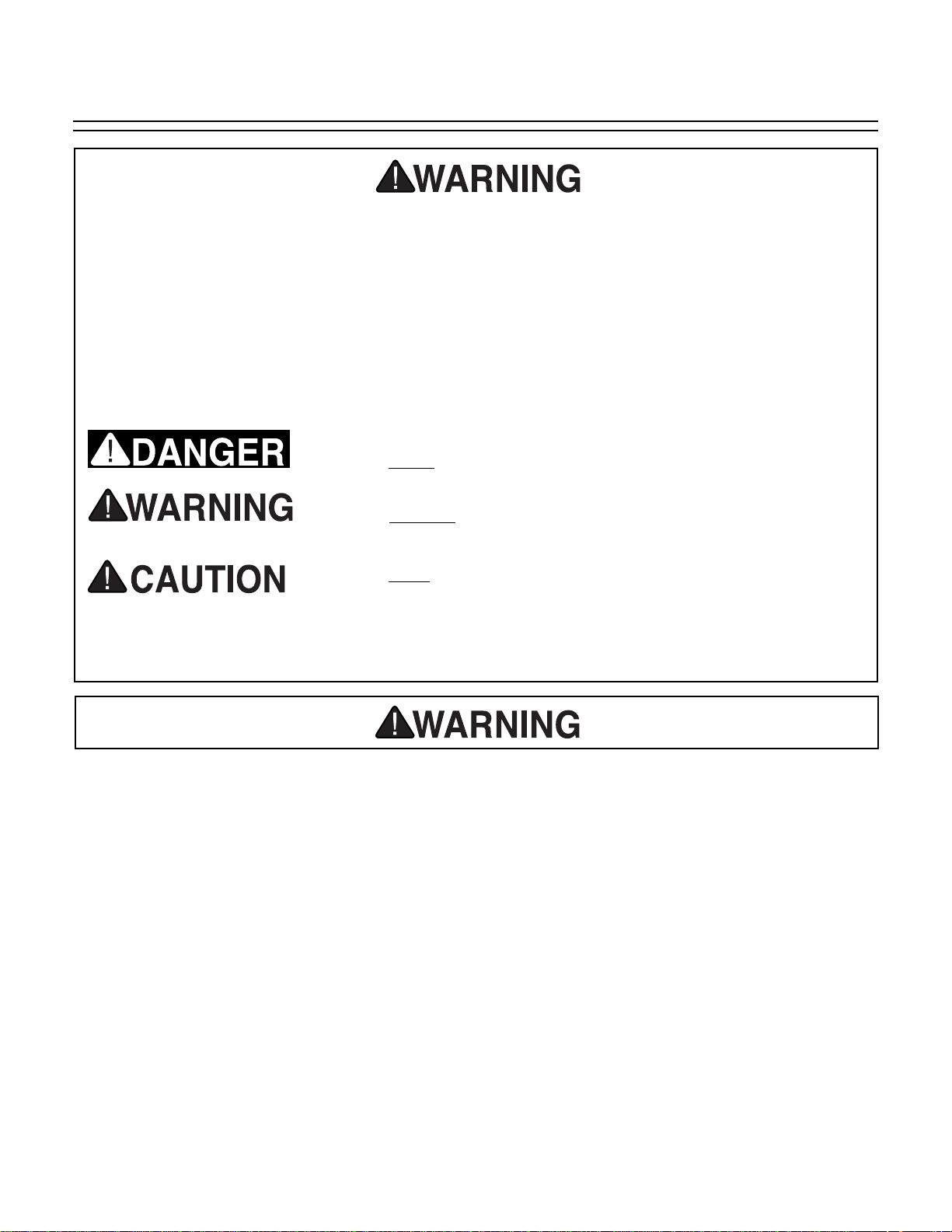
Indicates an imminently hazardous situation which, if not
avoided, WILL result in death or serious injury.
Indicates a potentially hazardous situation which, if not
avoided, COULD
result in death or serious injury.
Indicates a potentially hazardous situation which, if not
avoided, MAY
result in minor or moderate injury. It may also
be used to alert against unsafe practices.
This symbol is used to alert the user to useful information
about proper operation of the equipment.
The purpose of safety symbols is to attract your attention to possible hazardous conditions.
This manual uses a series of symbols and signal words which are intended to convey the level
of importance of the safety messages. The progression of symbols is described below.
Remember that safety messages by themselves do not eliminate danger and are not a substitute for proper accident prevention measures.
NOTICE
Page 5
G1013 Combination Sander -3-
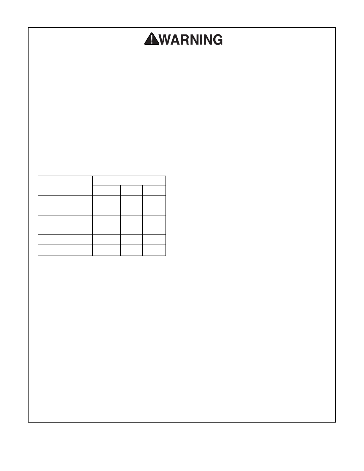
9. USE PROPER EXTENSION CORD. Make
sure your extension cord is in good condition. Conductor size should be in accordance with the chart below. The amperage
rating should be listed on the motor or tool
nameplate. An undersized cord will cause a
drop in line voltage resulting in loss of
power and overheating. Your extension
cord must also contain a ground wire and
plug pin. Always repair or replace extension cords if they become damaged.
Minimum Gauge for Extension Cords
10. WEAR PROPER APPAREL. Do not wear
loose clothing, gloves, neckties, rings,
bracelets, or other jewelry which may get
caught in moving parts. Non-slip footwear
is recommended. Wear protective hair covering to contain long hair.
11. ALWAYS USE SAFETY GLASSES. Also
use face or dust mask if cutting operation is
dusty. Everyday eyeglasses only have
impact resistant lenses, they are NOT safety glasses.
12. SECURE WORK. Use clamps or a vise to
hold work when practical. It’s safer than
using your hand and frees both hands to
operate tool.
13. NEVER OVERREACH. Keep proper foot-
ing and balance at all times.
LENGTH
AMP RATING 25ft 50ft 100ft
0-6 18 16 16
7-10 18 16 14
11-12 16 16 14
13-16 14 12 12
17-20 12 12 10
21-30 10 10 No
Safety Instructions For Power Tools
14. MAINTAIN TOOLS WITH CARE. Keep
tools sharp and clean for best and safest
performance. Follow instructions for lubricating and changing accessories.
15. DISCONNECT TOOLS before servicing
and changing accessories, such as blades,
bits, cutters, and the like.
16. REDUCE THE RISK OF UNINTENTIONAL STARTING. Make sure switch is in off
position before plugging in.
17. USE RECOMMENDED ACCESSORIES.
Consult the owner’s manual for recommended accessories. The use of improper
accessories may cause risk of injury.
18. CHECK DAMAGED PARTS. Before fur-
ther use of the tool, a guard or other part
that is damaged should be carefully
checked to determine that it will operate
properly and perform its intended function.
Check for alignment of moving parts, binding of moving parts, breakage of parts,
mounting, and any other conditions that
may affect its operation. A guard or other
part that is damaged should be properly
repaired or replaced.
19. NEVER LEAVE TOOL RUNNING UNATTENDED. TURN POWER OFF. Do not
leave tool until it comes to a complete stop.
20. NEVER USE UNDER THE INFLUENCE of
alcohol or drugs, or when tired.
21. NEVER ALLOW UNSUPERVISED OR
UNTRAINED PERSONNEL TO OPERATE THE MACHINE. Make sure any
instructions you give in regards to the
operation of the machine are approved,
correct, safe, and clearly understood.
Page 6
-4- G1013 Combination Sander
Additional Safety Instructions For Sanders
No list of safety guidelines can be complete. Every shop environment is different.
Always consider safety first, as it applies
to your individual working conditions. Use
this and other machinery with caution and
respect. Failure to do so could result in
serious personal injury, damage to equipment or poor work results.
1. BE AWARE OF BELT or disc rotation when
sanding.
2. KEEP FINGERTIPS AWAY from the mov-
ing belt or disc. Serious injury could result if
skin contacts abrasives or moving parts.
3. NEVER USE EXCESSIVE FORCE when
sanding. Doing this greatly increases the
chances of personal injury and motor overload.
4. ALWAYS FEED THE WORK against the
direction of rotation.
5. EVEN IF YOU HAVE A reliable method of
dust collection, use a dust mask or respirator when sanding, as well as eye and ear
protection.
6. IF THERE IS ANY doubt as to the stability
or integrity of the material to be sanded,
don’t sand it.
7. DO NOT OPERATE SANDER with a dam-
aged or badly worn disc or belt.
8. WHEN DISC SANDING, feed material into
the portion of the disc spinning down toward
the table.
9. TIE BACK LONG HAIR and remove any
loose-fitting clothing or jewelry that could be
caught up in the sander’s disc, belt, or other
moving machine parts.
10. HABITS — GOOD OR BAD — are hard to
break. Develop good habits and safety will
become second nature to you.
Operating this equipment has the potential
to propel debris into the air which can
cause eye injury. Always wear safety glasses or goggles when operating equipment.
Everyday glasses or reading glasses only
have impact resistant lenses, they are not
safety glasses. Be certain the safety glasses you wear meet the appropriate standards of the American National Standards
Institute (ANSI).
Like all power tools, there is danger associated with the Model G1013 Combination
Sander. Accidents are frequently caused
by lack of familiarity or failure to pay attention. Use this tool with respect and caution to lessen the possibility of operator
injury. If normal safety precautions are
overlooked or ignored, serious personal
injury may occur.
Page 7
G1013 Combination Sander -5-
110V Operation
SECTION 2: CIRCUIT REQUIREMENTS
A 15-amp fuse or circuit breaker should be used
when fusing this combination sander. Circuit
breakers rated any higher are not adequate to
protect the circuit from power surges.
Fusing
If you find it necessary to use an extension cord
with the Model G1013, make sure the cord is
rated Hard Service (grade S) or better. Refer to
the chart in the standard safety instructions to
determine the minimum gauge for the extension
cord. The extension cord must also contain a
ground wire and plug pin. Always repair or
replace extension cords when they become worn
or damaged.
Extension Cords
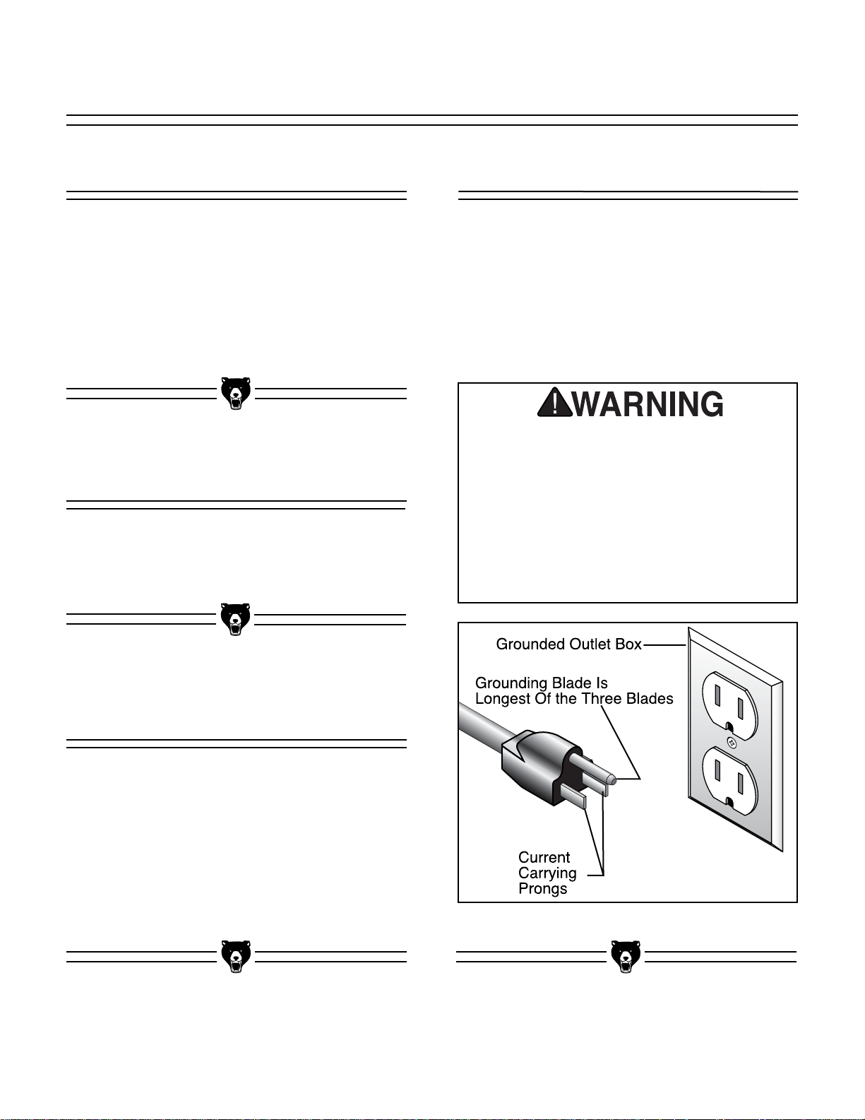
Grounding
This equipment must be grounded. Verify
that any existing electrical outlet and circuit
you intend to plug into is actually grounded. If it is not, it will be necessary to run a
separate 12 A.W.G. copper grounding wire
from the outlet to a known ground. Under
no circumstances should the grounding pin
from any three-pronged plug be removed.
Serious injury may occur.
In the event of an electrical short, grounding
reduces the risk of electric shock by providing a
path of least resistance to disperse electric current. This tool is equipped with a power cord hav-
ing an equipment-grounding conductor. See
Figure 1. The outlet must be properly installed
and grounded in accordance with all local codes
and ordinances.
The Model G1013 is wired for 110V, single-phase
operation only. The
1
⁄
2 H.P. motor will safely draw
12 amps at 110V. If you operate this sander on
any circuit that is already close to its capacity, it
might blow a fuse or trip a circuit breaker.
However, if an unusual load does not exist and a
power failure still occurs, contact a qualified electrician or our service department.
Figure 1. Grounded plug configuration.
Page 8

-6- G1013 Combination Sander
SECTION 3: Introduction
We are proud to offer the Grizzly Model G1013
Combination Sander. The Model G1013 is part of
a growing Grizzly family of fine woodworking
machinery. When used according to the guidelines set forth in this manual, you can expect
years of trouble-free, enjoyable operation and
proof of Grizzly’s commitment to customer satisfaction.
The Model G1013 is a combination 1" x 42" belt
and 8" disc sander that is capable of a wide variety of operations. The 1" wide belt enables you to
sand small or finely-detailed pieces as well as the
inside areas of closed loops. With the 8" disc and
table, larger surfaces can be sanded at many different angles. The Model G1013 comes complete
with motor and electrical package.
A number of sanding discs and belts for the
Model G1013 are available through the Grizzly
catalog.
We are also pleased to provide this manual with
the Model G1013. It was written to guide you
through assembly, review safety considerations,
and cover general operating procedures. It represents our effort to produce the best documentation possible. If you have any comments regarding this manual, please write to us at the address
below:
Grizzly Industrial, Inc.
C
/O Technical Documentation
P.O. Box 2069
Bellingham, WA 98227-2069
Most importantly, we stand behind our machines.
If you have any service questions or parts
requests, please call or write us at the location
listed below.
Grizzly Industrial, Inc.
1203 Lycoming Mall Circle
Muncy, PA 17756
Phone: (570) 326-3806
Fax: (800) 438-5901
E-Mail: techsupport@grizzlyindustrial.com
Web Site: http://www.grizzlyindustrial.com
The specifications, drawings, and photographs
illustrated in this manual represent the Model
G1013 as supplied when the manual was prepared. However, owing to Grizzly’s policy of continuous improvement, changes may be made at
any time with no obligation on the part of Grizzly.
Whenever possible, though, we send manual
updates to all owners of a particular tool or
machine. Should you receive one, we urge you to
insert the new information with the old and keep
it for reference.
Commentary
Read the manual before
assembly and operation.
Become familiar with
the machine and its
operation before beginning any work. Serious
personal injury may
result if safety or operational information is not
understood or followed.
Page 9
G1013 Combination Sander -7-
Unpacking
This Combination Sander is shipped from the
manufacturer in a carefully packed carton. If you
discover the machine is damaged after you’ve
signed for delivery, and the truck and driver are
gone, you will need to file a freight claim with the
carrier. Save the containers and all packing
materials for possible inspection by the carrier or
its agent. Without the packing materials, filing a
freight claim can be difficult. If you need assis-
tance determining whether you need to file a
freight claim, or with the procedure to file one,
please contact our Customer Service.
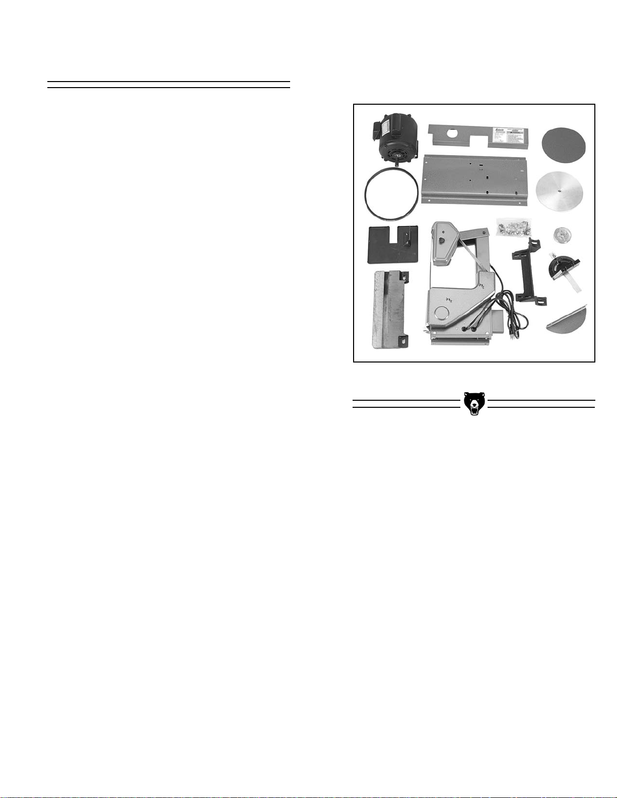
When you are completely satisfied with the condition of your shipment, you should inventory its
parts.
Figure 2. Overview of parts.
Page 10

-8- G1013 Combination Sander
Parts Inventory
After all the parts have been removed from the
carton, you should have:
• Belt Guard
• Disc Guard
• Disc Table
• Bolt Bag
• Table Support
• Sanding Unit
• Motor
• Miter Gauge
• Belt Table
• V-Belt
• Base
• Aluminum Disc
• Disc Sanding Paper
• Motor Pulley
NOTICE
A full parts list and breakdown drawing can
be found toward the end of this manual. For
easier assembly, or to identify missing
parts, please refer to the detailed illustrations at the end of the manual.
Hardware Qty
5
⁄16" - 18 x 5⁄8" Carriage Bolts 5
5
⁄16" - 18 x 3⁄4" Hex Bolts 4
5
⁄16" - 18 Hex Nuts 13
5
⁄16" Flat Washers 20
1
⁄4" - 20 x 11⁄4" Hex Bolts 4
1
⁄4" - 20 x 1" Hex Bolts 4
1
⁄4" - 20 Nuts 4
1
⁄4" Flat Washers 16
1
⁄4" - 20 x 11⁄4" Carriage Bolts 2
1
⁄4" - 20 Wing Nuts 2
M5-0.8 x 6mm Phillips
®
Head Screws 4
5mm Flat Washers 4
1
⁄4" - 20 x 3⁄8" Setscrews 2
3
⁄16" Sq. x 3⁄4" Keys 2
5
⁄16" Fender Washer 1
Rubber Feet 4
Wire Nuts 2
3mm Allen
®
Wrench 1
Page 11

G1013 Combination Sander -9-
Clean Up
BENCH LOAD
Your Model G1013 Combination Sander represents a relatively large weight load in a small footprint. Be sure that you workbench is adequately
reinforced to support the weight of the sander.
WORKING CLEARANCES
Working clearances can be thought of as the distances between machines and obstacles that
allow safe operation of every machine without
limitation. Ensure that your working area offers
plenty of room for free movement and a substantial amount of distance between you and others
that may be working in your shop area.
LIGHTING AND OUTLETS
Lighting should be bright enough to eliminate
shadow and prevent eye strain. Electrical circuits
should be dedicated or large enough to handle
combined motor amp loads. Outlets should be
located near each machine so power or extension cords are not obstructing high-traffic areas.
Be sure to observe local electrical codes for proper installation of new lighting, outlets, or circuits.
Site Consideration
The unpainted surfaces are coated with a waxy
oil to protect them from corrosion during shipment. Remove this protective coating with a solvent cleaner or citrus-based degreaser. Avoid
chlorine-based solvents as they may damage
painted surfaces should they come in contact.
Always follow the usage instructions on the product you choose for clean up.
Do not use gasoline or
other petroleum-based
solvents to clean with.
They have low flash
points which make them
extremely flammable. A
risk of explosion and
burning exists if these
products are used.
Serious personal injury
may occur.
Do not smoke while using
solvents. A risk of explosion or fire exists and may
result in serious personal
injury.
Many of the solvents
commonly used to clean
machinery can be toxic
when inhaled or ingested. Always work in wellventilated areas far from
potential ignition sources
when dealing with solvents. Use care when disposing of waste rags and
towels to be sure they do
not create fire or environmental hazards.
Make your shop “child safe.”
Ensure that your workplace
is inaccessible to children by
closing and locking all
entrances when you are
away. Never allow visitors in
your shop when assembling,
adjusting or operating equipment.
Page 12

-10- G1013 Combination Sander
SECTION 4: ASSEMBLY
Overview
The majority of your Combination Sander has
been assembled at the factory. The few remaining pieces will go together quickly and should be
done in the following order:
1. Feet to Base
2. Sanding Unit to Base
3. Table Support to Base
4. Motor to Base
5. Motor Pulley to Motor Shaft
6. V-Belt to Pulleys
7. Belt Guards to Sanding Unit
8. Aluminum Disc to Motor Shaft
9. Tables to Sanding Unit
10. Wiring motor
Only a few common tools are required to assemble your Combination Sander. Specifically, these
are: 6" adjustable wrench, 10mm open end
wrench, 12mm open end wrench, Phillips
®
head
screwdriver, 3mm Allen
®
wrench (supplied with
machine), and a rubber mallet.
Some metal parts may
have sharp edges on
them after they are
formed. Please examine
the edges of all metal
parts before handling
them. Failure to do so
could result in injury.
Assemble as follows:
1. Attach the four (4) rubber feet to the base
using the four (4)
1
⁄4" - 20 x 1" hex bolts, four
(4)
1
⁄4" flat washers and four (4) 1⁄4" - 20 hex
nuts. Be sure that the bolts protrude upward
through the base. See Figure 3.
Figure 4. Sanding unit mounted on base.
Figure 3. Order of foot attachment.
2. Place the preassembled Sanding Unit onto
the Base as shown in Figure 4. Secure with
the four (4)
5
⁄16" - 18 x 3⁄4" hex bolts, eight (8)
5
⁄16" flat washers, and four (4) 5⁄16" - 18 hex
nuts.
Assembly Process
Do not connect power to
the machine when performing any assembly.
Failure to do this may
result in serious personal injury.
Page 13

G1013 Combination Sander -11-
Figure 5. Table support mounted on base.
Figure 6. Motor mounted on base.
3. Attach the Disc Table Support to the base
using the four (4)
5
⁄16" - 18 x 11⁄4" hex bolts,
eight (8)
5
⁄16" washers, and four (4) 5⁄16" - 18
hex nuts. See Figure 5. Finger tighten for
now.
4. Mount the Motor to the base using the four
(4)
5
⁄16" - 18 x 5⁄8" carriage bolts, four (4) 5⁄16"
washers, and four (4)
5
⁄16" - 18 hex nuts. Be
sure that the bolts protrude upward through
the motor base. See Figure 6. Finger tighten
only.
Figure 8. Inspecting pulley alignment.
Figure 7. Motor pulley attachment.
6. Place the V-Belt onto the pulleys.
7. Set a straightedge across the edge of both
pulleys and adjust the position of the motor to
correct the pulley alignment. The straightedge should evenly touch each pulley when
they are aligned. See Figure 8.
5. Install the Motor Pulley onto the Motor Shaft.
Lightly tap into place with a rubber mallet if
necessary. Align the keyways on each and
insert the
3
⁄16'' square key. Secure with a 1⁄4" -
20 x
3
⁄8'' setscrew. See Figure 7.
Page 14

-12- G1013 Combination Sander
Figure 9. Belt guard attached to sander.
Figure 10. Belt table attached to sander.
9. Attach the belt guards as shown in Figure 9.
Secure with four (4) M5-0.8 x 6mm Phillips
®
head screws and 5mm washers.
10. Install the belt table using the
5
⁄16" - 18 x 5⁄8"
carriage bolt,
5
⁄16
" fender washer and
5
⁄16
" - 18
hex nut. See Figure 10.
Figure 12. Disc table attachment.
11. Slide the 8'' aluminum disc onto the motor
shaft. Lightly tap into place with a rubber
mallet if necessary. Align the disc and motor
shaft keyways and insert the
3
⁄16'' square key.
Secure the disc with a
1
⁄4" - 20 x 3⁄8'' setscrew.
See Figure 11.
Figure 11. 8" disc attached to motor.
12. Peel the backing from the new sanding disc
paper and stick it to the Aluminum Disc.
13. Secure the Disc Table to its support bracket
using the two (2)
1
⁄4
" - 20 x 1
1
⁄4
" carriage
bolts, two (2)
1
⁄4" flat washers and two (2) 1⁄4"
- 20 wing nuts. See Figure 12.
8. Move the motor back to set the belt tension.
The belt should deflect about
1
⁄2" per side
when squeezed in the middle with moderate
pressure. Tighten the motor down when tension is correct.
Page 15

G1013 Combination Sander -13-
Figure 13. Table aligned with sanding disc.
Figure 14. Cordset connection at motor.
14. Align the table so that there is a
1
⁄16'' gap
between the 8" disc and the table. See
Figure 13. Tighten the bolts that secure the
table support bracket to the base.
15. Wire the motor by removing the motor junc-
tion box cover and feed the power cord from
the switch through the plastic grommet at the
bottom of the junction box. Connect the
wires according to the Wiring Diagram Insert
included with this manual. If this insert is
missing, contact the appropriate service center listed in the Introduction for a replace-
ment. See Figure 14.
DO NOT attempt to connect or adjust wiring
with the cordset plugged into its power
source. Serious danger of electrocution
could result.
1
⁄16" Gap
Page 16

-14- G1013 Combination Sander
SECTION 5: Adjustments
Figure 16. Adjusting rear axle.
4. Move hands away from 8'' disc.
5. Plug sander into power and turn machine on
and off quickly. Inspect tracking.
6. Repeat steps 1-5 until the belt is centered on
the rollers.
If the belt tracks properly on the two front rollers,
but not on the rear roller, the rear roller must be
adjusted. The roller shaft axle is slightly bent. By
turning the axle, belt tracking will be affected.
1. Turn off the sander and disconnect it from its
power source.
2. Remove rear belt guard.
3. Using a 10mm wrench, turn the rear axle nut.
See Figure 16.
4. Keep rotating by hand until the sanding belt
rides in the center of the roller.
5. Replace the rear belt guard.
The idler and drive rollers are slightly crowned to
keep the belt centered on the rollers. This will not
correct improper tracking. Tracking must be periodically adjusted (particularly after belt replacement) to keep the belt properly aligned to the
rollers and the platen. To adjust tracking:
1. Unplug the machine!
2. Remove the Sanding Belt Table and
Sanding Belt Guards.
2. Turn the 8'' disc by hand to observe lateral
belt drift. DO NOT turn the sander on to
inspect for belt drift.
3. By sight, center the Sanding Belt by adjusting the tracking knob. See Figure 15.
Figure 15. Location of tracking adjustments.
Tracking Knob
Rear Axle Nut
Lock Knob
Belt Tracking
With the exception of
belt tracking, adjustments to your Sander
should be made with the
power off and the
machine unplugged!
Page 17

G1013 Combination Sander -15-
Once you have turned off the switch and disconnected the sander from its power source:
1. Loosen the hex nut as shown in Figure 18.
2. Tilt the table to the desired position.
3. Tighten the hex nut.
Belt Table Tilt
Figure 18. Belt table in tilted position.
Once you have turned off the switch and disconnected the sander from its power source:
1. Remove the two Sanding Belt Guards.
2. Press down on the top arm to release the
belt tension and remove the old belt. See
Figure 17.
Note: you may find it easier to remove and
replace the belt with the belt table either
tipped down to 45˚ or completely removed.
3. Install new belt. Arrows on underside of the
belt should point in the direction of roller
travel. If your belt has no arrows, install it so
that the overlap on the seam travels downward (when facing the machine). Otherwise
the paper will catch on your stock and rip.
Release the arm.
4. Replace the Sanding Belt Guards.
Belt Replacement
Figure 17. Sanding belt removal.
Page 18

-16- G1013 Combination Sander
Once you have turned off the switch and disconnected the sander from its power source:
1. Remove the Sanding Disc Table.
2. Peel off the old Sanding Disc. Remove the
backing from the new Disc, center it and
press it firmly into place.
3. It may become necessary to remove the
Aluminum Disc from the Motor Shaft
because the Sanding Disc cannot be peeled
off or the Aluminum Disc requires cleaning.
Do not use petroleum-based solvents to
clean the surface of the aluminum disc. This
adversely affects adhesion.
Once you have turned off the switch and disconnected the sander from its power source:
1. Loosen the two wing nuts under the sanding
disc table. See Figure 19.
2. Tilt the table to the desired position.
3. Tighten the wing nuts.
Disc Table Tilt
Figure 19. Disc table in tilted position.
Disc Replacement
Page 19

G1013 Combination Sander -17-
SECTION 6: Operations
Before you put your Combination Sander into
use, give it a quick inspection with the machine
switched off and disconnected from its power
source.
1. Are all fasteners tight?
2. Is the sanding belt properly tracked and ten-
sioned?
3. Rotate disc slowly by hand. Look and listen
for any scraping noises or anything that
impedes smooth movement. Make appropriate adjustments before attempting to run the
machine.
4. If the sander appears to be free of problems
that might affect its operation, plug it in to its
power source and start the machine. Be sure
to keep a finger on the OFF button, just in
case of a problem with the machine. Run the
sander briefly to allow inspection of belt
tracking.
5. Turn off the machine, disconnect it from its
power source, and re-inspect for loose fasteners. If the tracking is not correct, refer to
the tracking adjustment guidelines in the
Adjustments section.
Never use the Model G1013 for applications
other than those for which it was made. DO
NOT overload the machine or use excess
force when sanding. Severe personal
injury, damage to the machine, or damage
to your workpiece could occur.
Test-Run
Keep loose clothing out
of the way of machinery
and keep hair pulled
back.
Wear safety glasses during all operations on the
shaper. Failure to comply may result in serious
personal injury.
Disconnect power to the
machine when performing any adjustments or
maintenance. Failure to
do this may result in serious personal injury.
Always wear a dust mask
when operating the
sander. Using this
machine produces sawdust which may cause
allergic reactions or respiratory problems.
Page 20

-18- G1013 Combination Sander
For general wood sanding, position and secure
table, turn the machine on, and slowly feed your
workpiece into the belt or disc. For disc sanding,
note the direction of the disc rotation and be sure
to feed your workpiece into the disc’s downward
spin. Also, be sure to keep the work table about
1
⁄16" away from the belt or disc.
Remove platen and move Small Upper Idler
Roller rearward so the workpiece will not be accidentally forced against it. Slowly feed the workpiece into the belt; the belt will follow the contour
of the workpiece. See Figure 20.
Figure 20. Contour sanding.
General Sanding Contour Sanding
Page 21

G1013 Combination Sander -19-
Figure 21. Belt arrangement for inside sanding.
To sand or grind an interior work area, the sanding belt must be fed through the workpiece and
remounted on its rollers. Depending on your
application, you may either remove the platen or
keep it in place.
1. Remove the Belt Sanding Table and the Belt
Guards.
2. Feed the Sanding Belt through the work-
piece and over the Upper Idler Roller.
Loosen the Small Upper Idler Roller, swing it
toward the front of the machine, and feed the
belt around the pulley.
3. Press down on the top arm and feed the
remainder of the belt through the rollers as
shown in Figure 21.
4. Replace guards and table.
5. Adjust belt tracking as described in
Adjustments section.
Figure 22. False table for sharpening support.
Tilt the table to the desired sharpening angle and
secure it. Using C-Clamps, attach a suitable
wood scrap to the table. See Figure 22. This acts
as an auxiliary table to support the workpiece.
This table should be
1
⁄16" away from the belt. It
may be necessary to cut a notch in your auxiliary
table to achieve this clearance.
Inside Sanding
Sharpening
Page 22

-20- G1013 Combination Sander
SECTION 7: MAINTENANCE
General
Table
Your combination sander is equipped with shielded and pre-lubricated ball bearings that require
no lubrication for the life of the bearings. All bearings are common sizes and are readily available
from a local bearing supply house or our Service
Department. The roller shafts, however, will benefit from regular applications of light machine oil.
See Figure 23.
The working table and other non-painted surfaces on the Model G1013 should be protected
against rust and pitting. Wiping the sander clean
after every use ensures that sawdust is not
allowed to trap moisture against bare metal surfaces.
Tables can be kept rust-free with regular applications of products like Boeshield
®
T-9. For long
term storage you may want to consider products
like Kleen Bore's Rust Guardit™.
Make a habit of inspecting your sander each time
you use it. Check for the following conditions and
repair or replace when necessary.
1. Loose mounting bolts.
2. Worn switch.
3. Worn or damaged cords and plugs.
4. Worn or damaged V-belt.
5. Poor belt tensioning ⁄ tracking.
Figure 23. Lubrication points.
Lubrication
Disconnect power to the
machine when performing any adjustments or
maintenance. Failure to
do this may result in serious personal injury.
Page 23

G1013 Combination Sander -21-
Maintenance Performed
Approximate Hours Of Use
Maintenance Notes
Date
Page 24

-22- G1013 Combination Sander
The following pages contain general machine
data, parts diagrams/lists, troubleshooting guide
and Warranty/Return information for your Model
G1013 Combination Sander.
If you need parts or help in assembling your
machine, or if you need operational information,
we encourage you to call our Service
Department. Our trained service technicians will
be glad to help you.
If you have comments dealing specifically with
this manual, please write to our Bellingham,
Washington location using the address in Section
3: Introduction. The specifications, drawings, and
photographs illustrated in this manual represent
the Model G1013 as supplied when the manual
was prepared. However, due to Grizzly’s policy of
continuous improvement, changes may be made
at any time with no obligation on the part of
Grizzly. Whenever possible, though, we send
manual updates to all owners of a particular tool
or machine. Should you receive one, add the new
information to this manual and keep it for reference.
We have included some important safety measures that are essential to this machine’s operation. While most safety measures are generally
universal, Grizzly reminds you that each workshop is different and safety rules should be considered as they apply to your specific situation.
We recommend you keep a copy of our current
catalog for complete information regarding
Grizzly's warranty and return policy. If you need
additional technical information relating to this
machine, or if you need general assistance or
replacement parts, please contact the Service
Department listed in Section 3: Introduction.
Additional information sources are necessary to
realize the full potential of this machine. Trade
journals, woodworking magazines, and your local
library are good places to start.
SECTION 8: CLOSURE
The Model G1013 was specifically designed
for sanding operations only. DO NOT MODIFY AND/OR USE THIS MACHINE FOR ANY
OTHER PURPOSE. Modifications or
improper use of this tool will void the warranty. If you are confused about any aspect
of this machine, DO NOT use it until you
have answered all your questions. Serious
personal injury may occur.
Like all power tools, there is danger associated with the Model G1013 Combination
Sander. Accidents are frequently caused by
lack of familiarity or failure to pay attention.
Use this tool with respect and caution to
lessen the possibility of operator injury. If
normal safety precautions are overlooked
or ignored, serious personal injury may
occur.
Operating this equipment has the potential
to launch flying debris which could cause
eye injury. Always wear safety glasses or
goggles when operating equipment.
Everyday glasses or reading glasses only
have impact resistant lenses, they are not
safety glasses. Be certain the safety glasses you wear meet the appropriate standards of the American National Standards
Institute (ANSI).
Page 25

G1013 Combination Sander -23-
Customer Service #: (570) 326-3806 • To Order Call: (800) 523-4777 • Fax #: (800) 438-5901
MACHINE DATA
SHEET
Design Type.................................................................................................... Bench Model
Overall Dimensions:
Base ................................................................................................................10" x 18"
Height ......................................................................................................................21"
Width ........................................................................................................................15"
Length ......................................................................................................................24"
Table (Disc) ....................................................................................................5" x 12
1
⁄2"
Table (Belt)...................................................................................................... 6
1
⁄2" x 8"
Container Dimensions........................................................................10" x 19
1
⁄2" x 21"
Weight ................................................................................................................55 lbs.
Foot Print ........................................................................................................18" x 10"
Capacities:
Sanding Belt......................................................................................................1" x 42"
Sanding Belt Speed ..................................................................................4000 F.P.M.
Aluminum Disc............................................................................................8" Diameter
Aluminum Disc Speed ..............................................................................1720 R.P.M.
Miter Gauge Groove..........................................................................................
3
⁄8" x 3⁄4"
Miter Gauge................................................................Die Cast Plastic / Aluminum Bar
Table Tilt Range ................................................................................................0° - 45°
Construction:
Base ......................................................................................................Stamped Steel
Table (Disc)........................................................................................Ground Cast Iron
Stand......................................................................................................Stamped Steel
Table (Belt) ............................................................................................Stamped Steel
Motor:
Type ......................................................................................Capacitor Start Induction
Horsepower ........................................................................................................
1
⁄2 H.P.
Voltage ................................................................................................................ 110V
Amps..........................................................................................................................12
Cycle and R.P.M. ......................................................................60 Hertz ⁄ 1720 R.P.M.
Switch....................................................................................................On ⁄ Off Toggle
Power Transfer ..............................................................................................Belt Drive
Bearings ....................................................................Sealed, Permanently Lubricated
Specifications, while deemed accurate, are not guaranteed.
GRIZZLY MODEL G1013 COMBINATION SANDER
Page 26

Page 27

G1013 Combination Sander -25-
PARTS LIST
1 P1013001 GUARD BACK
2 PWN01 WING NUT 10-24
3 P1013003 TOP PIVOT BRACKET
4 P1013004 KNOB BOLT
1
⁄4-20 X 1"
5 PEC03M E-CLIP 10mm
6 P1013006 UPPER WHEEL SHAFT
7 P1013007 SPECIAL CLIP
8 P6200 BEARING 6200-2RS
9 P1013009 TOP WHEEL
10 PR01M SNAP RING 10mm
11 PLW02 LOCK WASHER
1
⁄4"
12 PN05 HEX NUT
1
⁄4" - 20
13 P1013013 UPPER GUARD
14 PW03M FLAT WASHER 6mm
15 P1013015 KNOB BOLT
1
⁄4"-20 X 1⁄2"
16 PS19M PHLP HD SCR M5 - 0.8 x 6
17 P1013017 COMPLETE MITER GAUGE
18 P1013018 TOP ARM
19 P1013019 IDLER SHAFT
20 P1013020 SLEEVE BEARING
21A P1013021A IDLER WHEEL
22 PW03 FLAT WASHER #10
22A P1012022A PLASTIC WASHER
23 PB12 HEX BOLT
5
⁄16" - 18 x 11⁄4"
24 P1013024 TORSION SPRING
25 P1013025 PIVOT ARM SHAFT
26 P1013026 BELT GUARD
27 PB04M HEX BOLT M6 - 1.0 x 10
28 P1013028 IDLER SHAFT
29 PEC07M E-CLIP 7mm
30A PK34M KEY 5 x 5 x 20mm
30B P1013030B MOTOR PULLEY
31A PVM30 V-BELT M-30
32 P1013032 MOTOR
1
⁄2 HP
33 PN02 HEX NUT
5
⁄16" - 18
34 PW06 FLAT WASHER
1
⁄4"
35 PSW05 SWITCH W⁄ MOUNTING NUT
36A PCB01 CARRIAGE BOLT
5
⁄16"-18x5⁄8"
37 P1013037 RUBBER FOOT
38 PB31 HEX BOLT
1
⁄4" - 20 x 1"
39 P1013039 BASE
REF PART # DESCRIPTION REF PART # DESCRIPTION
40 P1013040 DRIVE WHEEL
41 PSS03 SETSCREW
1
⁄4" - 20 x3⁄8"
42 P1013042 PLATE, RIGHT HAND
43 P1013043 GUARD SUPPORT
44 PB07 HEX BOLT
5
⁄16" - 18 x 3⁄4"
45 P1013045 LOWER GUARD
46 G1209 SANDING BELT
47 P1013047 TABLE SUPPORT
48 P1013048 BELT PLATEN
49 P6202 BEARING 6202-2RS
50 P1013050 FENDER WASHER
5
⁄16"
51 P1013051 SHAFT
52 PR05M SNAP RING 15mm
53 P1013053 BEARING CAP
54 P1013054 ARBOR BEARING HOUSING
55A P1013055A PULLEY
56 P1013056 GUARD BRACKET
57 P1013057 PLATE, LEFT HAND
59 P1013059 BELT TABLE
60 P1013060 COLUMN CHANNEL
63 P1013063 8" ALUMINUM DISC
64 PCB07 CARRIAGE BOLT
1
⁄4
" - 20 x 1
1
⁄4
"
65 P1013065 DISC TABLE
66 P1013066 TABLE SUPPORT
67 PWN02 WING NUT
1
⁄4
" - 20
68 G1212 8" SAND DISC
69 PW02M FLAT WASHER 5mm
70 P1013070 DISC COVER
71 P1013071 SWITCH COVER
72 P1013072 POWER CORD
73 P1013073 BUSHING
74 P1013074 CORD SUPPORT
75 PN07 HEX NUT 10 - 24
76 PB02M HEX BOLT M6-1.0 x 12
77 PW07 FLAT WASHER
5
⁄16"
78 P1013078 RUBBER WASHER
79 P1013079 MOTOR CORD
80 P1013080 ON ⁄ OFF LABEL
81 PS08 PHLP HD SCR 10 - 24 x
3
⁄4"
82 PR03M SNAP RING 12mm
83 P1013083 SPACER
Page 28

-26- G1013 Combination Sander
WARRANTY AND RETURNS
Grizzly Industrial, Inc. warrants every product it sells for a period of 1 year to the original purchaser from
the date of purchase. This warranty does not apply to defects due directly or indirectly to misuse, abuse,
negligence, accidents, repairs or alterations or lack of maintenance. This is Grizzly’s sole written warranty
and any and all warranties that may be implied by law, including any merchantability or fitness, for any particular purpose, are hereby limited to the duration of this written warranty. We do not warrant or represent
that the merchandise complies with the provisions of any law or acts unless the manufacturer so warrants.
In no event shall Grizzly’s liability under this warranty exceed the purchase price paid for the product and
any legal actions brought against Grizzly shall be tried in the State of Washington, County of Whatcom.
We shall in no event be liable for death, injuries to persons or property or for incidental, contingent, special, or consequential damages arising from the use of our products.
To take advantage of this warranty, contact us by mail or phone and give us all the details. We will then
issue you a “Return Number,’’ which must be clearly posted on the outside as well as the inside of the carton. We will not accept any item back without this number. Proof of purchase must accompany the merchandise.
The manufacturers reserve the right to change specifications at any time because they constantly strive to
achieve better quality equipment. We make every effort to ensure that our products meet high quality and
durability standards and we hope you never need to use this warranty.
Please feel free to write or call us if you have any questions about the machine or the manual.
Thank you again for your business and continued support. We hope to serve you again soon.
Page 29

G1013 Combination Sander -27-
CUT ALONG DOTTED LINE
10. Which benchtop tools do you own? Check all that apply.
___1" x 42" Belt Sander ___6" - 8" Grinder
___5" - 8" Drill Press ___Mini Lathe
___8" Table Saw ___10" - 12" Thickness Planer
___8" - 10" Bandsaw ___Scroll Saw
___Disc/Belt Sander ___Spindle/Belt Sander
___Mini Jointer
___Other__________________________________________________
11. How many of the machines checked above are Grizzly? ____________
12. Which portable/hand held power tools do you own? Check all that apply.
___Belt Sander ___Orbital Sander
___Biscuit Joiner ___Palm Sander
___Circular Saw ___Portable Planer
___Detail Sander ___Saber Saw
___Drill/Driver ___Reciprocating Saw
___Miter Saw ___Router
___Other__________________________________________________
13. What machines/supplies would you like Grizzly Industrial to carry?
__________________________________________________________
__________________________________________________________
__________________________________________________________
__________________________________________________________
14. What new accessories would you like Grizzly Industrial to carry?
__________________________________________________________
__________________________________________________________
__________________________________________________________
__________________________________________________________
15. What other companies do you purchase your tools and supplies from?
__________________________________________________________
__________________________________________________________
16. Do you think your purchase represents good value?
___Yes ___No
17. Would you recommend Grizzly Imports to a friend?
___Yes ___No
18. Would you allow us to use your name as a reference for Grizzly customers
in your area? Note: We never use names more than three times.
___Yes ___No
19. Comments:_________________________________________________
__________________________________________________________
__________________________________________________________
__________________________________________________________
__________________________________________________________
1. How did you learn about us?
___Advertisement ___Friend
___Catalog ___Card Deck
___World Wide Web
___Other__________________________________________________
2. Which of the following magazines do you subscribe to.
___American Woodworker ___Practical Homeowner
___Cabinetmaker ___Shop Notes
___Family Handyman ___Today’s Homeowner
___Fine Homebuilding ___WOOD
___Fine Woodworking ___Wooden Boat
___Home Handyman ___Woodshop News
___Journal of Light Construction ___Woodsmith
___Old House Journal ___Woodwork
___Popular Mechanics ___Woodworker
___Popular Science ___Woodworker’s Journal
___Popular Woodworking ___Workbench
___Other__________________________________________________
3. Which of the following woodworking/remodeling shows do you watch?
___Backyard America ___The New Yankee Workshop
___Home Time ___This Old House
___The American Woodworker ___Woodwright’s Shop
___Other__________________________________________________
4. What is your annual household income?
___$20,000-$29,999 ___$60,000-$69,999
___$30,000-$39,999 ___$70,000-$79,999
___$40,000-$49,999 ___$80,000-$89,999
___$50,000-$59,999 ___$90,000 +
5. What is your age group?
___20-29 ___50-59
___30-39 ___60-69
___40-49 ___70 +
6. How long have you been a woodworker?
___0 - 2 Years ___8 - 20 Years
___2 - 8 Years ___20+ Years
7. How would you rank your woodworking skills?
___Simple ___Advanced
___Intermediate ___Master Craftsman
8. What stationary woodworking tools do you own? Check all that apply.
___Air Compressor ___Panel Saw
___Band Saw ___Planer
___Drill Press ___Power Feeder
___Drum Sander ___Radial Arm Saw
___Dust Collector ___Shaper
___Horizontal Boring Machine ___Spindle Sander
___Jointer ___Table Saw
___Lathe ___Vacuum Veneer Press
___Mortiser ___Wide Belt Sander
___Other__________________________________________________
9. How many of your woodworking machines are Grizzly? _____________
Name ____________________________________________________________________________________
Street ____________________________________________________________________________________
City ______________________________________________________________State________Zip_________
Phone Number_______________________E-Mail_______________________FAX________________________
MODEL#_____________________SERIAL#_______________________Order___________________________
The following information is given on a voluntary basis. It will be used for marketing purposes to help us develop better products and services. Of
course, all information is strictly confidential.
WARRANTY CARD
Page 30

FOLD ALONG DOTTED LINE
FOLD ALONG DOTTED LINE
GRIZZLY INDUSTRIAL, INC.
P.O. BOX 2069
BELLINGHAM, WA 98227-2069
Place
Stamp
Here
TAPE ALONG EDGES--PLEASE DO NOT STAPLE
Name_______________________________
Street_______________________________
City______________State______Zip______
Send a Grizzly Catalog to a friend:
Page 31

Page 32

 Loading...