

Page 1

18" HEAVY-DUTY BANDSAW
MODEL G1012
INSTRUCTION MANUAL
COPYRIGHT © 1992 BY GRIZZLY INDUSTRIAL, INC. REG.# TX 3170 590
WARNING: NO PORTION OF THIS MANUAL MAY BE REPRODUCED IN ANY SHAPE
OR FORM WITHOUT THE WRITTEN APPROVAL OF GRIZZLY INDUSTRIAL, INC.
REVISED FEBRUARY 2002, PRINTED IN TAIWAN
Page 2

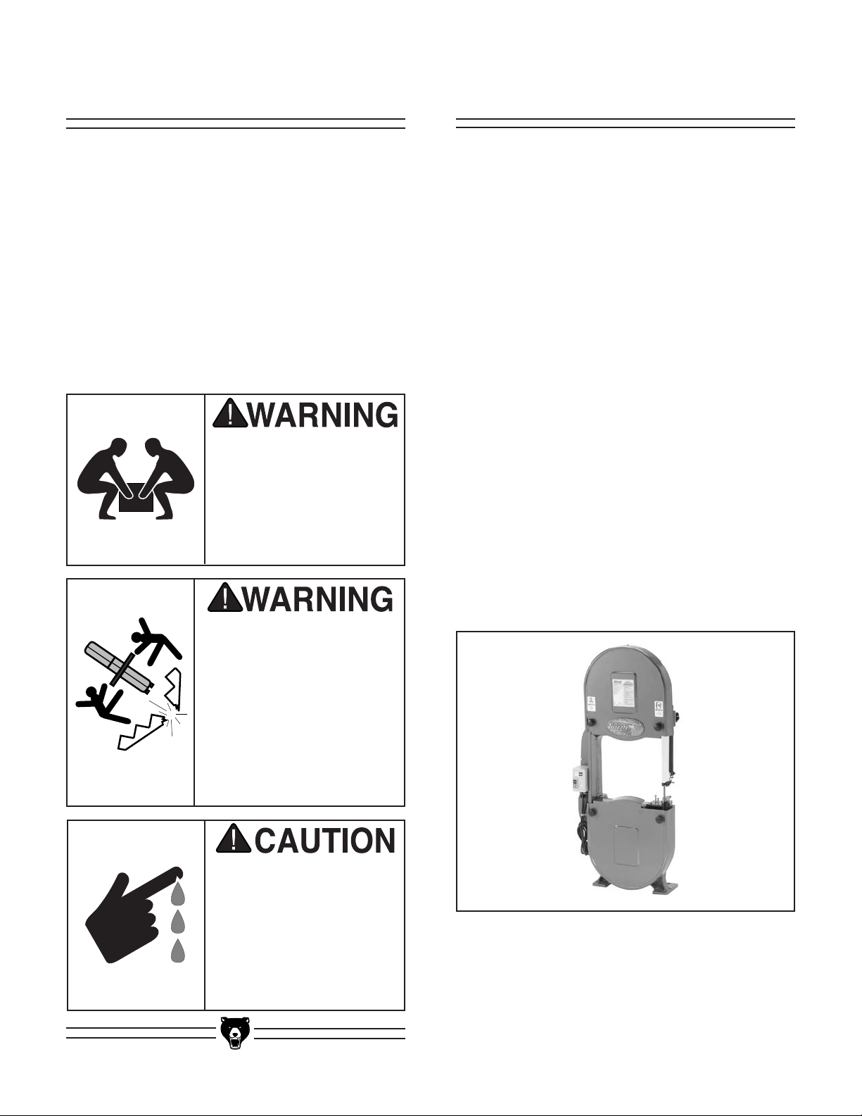
WARNING
Some dust created by power sanding, sawing, grinding, drilling, and other construction activities contains
chemicals known to the State of California to cause
cancer, birth defects or other reproductive harm.
Some examples of these chemicals are:
• Lead from lead-based paints.
• Crystalline silica from bricks, cement, and
other masonry products.
• Arsenic and chromium from chemically treated
lumber.
Your risk from these exposures varies, depending on
how often you do this type of work. To reduce your
exposure to these chemicals: work in a well ventilated
area, and work with approved safety equipment, such
as those dust masks that are specially designed to filter out microscopic particles.
Page 3

Table Of Contents
PAGE
1. SAFETY ..........................................................................................................................2
SAFETY RULES FOR ALL TOOLS ......................................................................2-3
ADDITIONAL SAFETY INSTRUCTIONS FOR BANDSAWS....................................4
2. CIRCUIT REQUIREMENTS ............................................................................................5
220V OPERATION ....................................................................................................5
FUSING ....................................................................................................................5
GROUNDING ............................................................................................................6
EXTENSION CORDS ................................................................................................6
3. GENERAL INFORMATION ............................................................................................7
UNPACKING..............................................................................................................8
PIECE INVENTORY ..............................................................................................8-9
HARDWARE BAGS ..................................................................................................9
HARDWARE RECOGNITION CHART ....................................................................10
CLEAN UP ..............................................................................................................11
SITE CONSIDERATIONS ......................................................................................11
4. ASSEMBLY ..................................................................................................................12
ORDER OF ASSEMBLY ........................................................................................12
STAND................................................................................................................12-14
PULLEYS ................................................................................................................15
V-BELTS ............................................................................................................16-17
BELT GUARD..........................................................................................................17
TABLE ................................................................................................................18-19
BLADE GUIDES ......................................................................................................19
FENCE ....................................................................................................................19
5. ADJUSTMENTS ............................................................................................................20
CONTROLS ............................................................................................................20
BLADE TRACKING ................................................................................................21
BLADE TENSION ....................................................................................................21
GUIDE POST ..........................................................................................................22
BLADE GUIDES ................................................................................................22-23
BLADE CHANGES ..................................................................................................24
TABLE ADJUSTMENTS ....................................................................................24-25
FENCE ADJUSTMENT ..........................................................................................26
BLADE LEAD ....................................................................................................26-27
WHEEL ALIGNMENT ........................................................................................27-28
6. OPERATIONS ..............................................................................................................29
TEST RUN ..............................................................................................................29
OVERVIEW ........................................................................................................29-30
BLADE INFORMATION......................................................................................30-31
RIPPING ..................................................................................................................32
CROSSCUTTING ..............................................................................................32-33
RESAWING ............................................................................................................33
CUTTING CURVES ................................................................................................34
STACKED CUTS ....................................................................................................34
7. MAINTENANCE ............................................................................................................35
V-BELTS ..................................................................................................................35
MISCELLANEOUS ..................................................................................................35
TABLE......................................................................................................................35
LUBRICATION ........................................................................................................35
WIRE DIAGRAM......................................................................................................36
8. CLOSURE ....................................................................................................................37
MACHINE DATA......................................................................................................38
PARTS BREAKDOWN AND PARTS LISTS ......................................................39-44
TROUBLESHOOTING ............................................................................................45
WARRANTY AND RETURNS ................................................................................46
Page 4

-2- G1012 18" Bandsaw
Safety Instructions For Power Tools
SECTION 1: SAFETY
5. KEEP CHILDREN AND VISITORS
AWAY. All children and visitors should be
kept a safe distance from work area.
6. MAKE WORKSHOP CHILD PROOF with
padlocks, master switches, or by removing
starter keys.
7. DO NOT FORCE TOOL. It will do the job
better and safer at the rate for which it was
designed.
8. USE RIGHT TOOL. Do not force tool or
attachment to do a job for which it was not
designed.
1. KEEP GUARDS IN PLACE and in working
order.
2. REMOVE ADJUSTING KEYS AND
WRENCHES. Form habit of checking to
see that keys and adjusting wrenches are
removed from tool before turning on.
3. KEEP WORK AREA CLEAN. Cluttered
areas and benches invite accidents.
4. DO NOT USE IN DANGEROUS ENVIRONMENT. Do not use power tools in
damp or wet locations, or where any flammable or noxious fumes may exist. Keep
work area well lighted.
For Your Own Safety Read Instruction
Manual Before Operating This Equipment
Indicates an imminently hazardous situation which, if not avoided,
WILL result in death or serious injury.
Indicates a potentially hazardous situation which, if not avoided,
COULD result in death or serious injury.
Indicates a potentially hazardous situation which, if not avoided,
MAY result in minor or moderate injury. It may also be used to alert
against unsafe practices.
This symbol is used to alert the user to useful information about
proper operation of the equipment.
The purpose of safety symbols is to attract your attention to possible hazardous conditions. This
manual uses a series of symbols and signal words which are intended to convey the level of
importance of the safety messages. The progression of symbols is described below. Remember
that safety messages by themselves do not eliminate danger and are not a substitute for proper
accident prevention measures.
NOTICE
Page 5
G1012 18" Bandsaw -3-
9. USE PROPER EXTENSION CORD. Make
sure your extension cord is in good condition. Conductor size should be in accordance with the chart below. The amperage
rating should be listed on the motor or tool
nameplate. An undersized cord will cause
a drop in line voltage resulting in loss of
power and overheating. Your extension
cord must also contain a ground wire and
plug pin. Always repair or replace extension cords if they become damaged.
Minimum Gauge for Extension Cords
10. WEAR PROPER APPAREL. Do not wear
loose clothing, gloves, neckties, rings,
bracelets, or other jewelry which may get
caught in moving parts. Non-slip footwear
is recommended. Wear protective hair covering to contain long hair.
11. ALWAYS USE SAFETY GLASSES. Also
use face or dust mask if cutting operation is
dusty. Everyday eyeglasses only have impact
resistant lenses, they are NOT safety glasses.
12. SECURE WORK. Use clamps or a vise to hold
work when practical. It is safer than using your
hand and frees both hands to operate tool.
13. DO NOT OVERREACH. Keep proper foot-
ing and balance at all times.
14. MAINTAIN TOOLS WITH CARE. Keep
tools sharp and clean for best and safest
performance. Follow instructions for lubricating and changing accessories.
Safety Instructions For Power Tools
15. USE RECOMMENDED ACCESSORIES.
Consult the owner’s manual for recommended accessories. The use of improper
accessories may cause risk of injury.
16. REDUCE THE RISK OF UNINTENTION-
AL STARTING. On machines with mag-
netic contact starting switches there is a
risk of starting if the machine is bumped or
jarred. Always disconnect from power
source before adjusting or servicing. Make
sure switch is in OFF position before reconnecting.
17. MANY WOODWORKING TOOLS CAN
“KICKBACK” THE WORKPIECE toward
the operator if not handled properly. Know
what conditions can create “kickback” and
know how to avoid them. Read the manual
accompanying the machine thoroughly.
18. CHECK DAMAGED PARTS. Before further use of the tool, a guard or other part
that is damaged should be carefully
checked to determine that it will operate
properly and perform its intended function.
Check for alignment of moving parts, binding of moving parts, breakage of parts,
mounting, and any other conditions that
may affect its operation. A guard or other
part that is damaged should be properly
repaired or replaced.
19. NEVER LEAVE TOOL RUNNING UNATTENDED. TURN POWER OFF. Do not
leave tool until it comes to a complete stop.
20. NEVER OPERATE A MACHINE WHEN
TIRED, OR UNDER THE INFLUENCE OF
DRUGS OR ALCOHOL. Full mental alert-
ness is required at all times when running
a machine.
21. NEVER ALLOW UNSUPERVISED OR
UNTRAINED PERSONNEL TO OPERATE THE MACHINE. Make sure any
instructions you give in regards to the
operation of the machine are approved,
correct, safe, and clearly understood.
LENGTH
AMP RATING 25ft 50ft 100ft
0-6 18 16 16
7-10 18 16 14
11-12 16 16 14
13-16 14 12 12
17-20 12 12 10
21-30 10 10 No
Page 6

-4- G1012 18" Bandsaw
Additional Safety Instructions For Bandsaws
7. ALWAYS FEED STOCK EVENLY AND
SMOOTHLY. Do not force or twist blade
while cutting, especially when sawing
small radii.
8. THIS MACHINE IS NOT DESIGNED TO
CUT METAL or other material except
wood.
9. BLADE SHOULD BE RUNNING AT
FULL SPEED before beginning a cut.
10. DO NOT MANUALLY STOP OR SLOW
BLADE after turning the saw off. Allow it to
come to a complete stop before you leave
it unattended.
11. ALL INSPECTIONS, ADJUSTMENTS,
AND MAINTENANCE ARE TO BE DONE
WITH THE POWER OFF and the plug
pulled from the outlet. Wait for all moving
parts to come to a complete stop.
12. HABITS – GOOD AND BAD – ARE
HARD TO BREAK. Develop good habits
in your shop and safety will become second-nature to you.
13. IF AT ANY TIME YOU ARE EXPERIENC-
ING DIFFICULTIES PERFORMING THE
INTENDED OPERATION, STOP USING
THE BANDSAW! Then contact our ser-
vice department or ask a qualified expert
how the operation should be performed.
1. DO NOT OPERATE WITH DULL OR
BADLY WORN BLADES. Dull blades
require more effort to use and are difficult
to control. Inspect blades before each use.
2. NEVER POSITION FINGERS OR
THUMBS IN LINE WITH THE CUT.
Serious personal injury could occur.
3. DO NOT OPERATE THIS BANDSAW
WITHOUT WHEEL, PULLEY, AND
BLADE GUARDS IN PLACE.
4. WHEN REPLACING BLADES, make sure
the teeth face down toward the table. The
force of the cut is always down. Make sure
the blade is properly tensioned.
5. CUTS SHOULD ALWAYS BE FULLY
SUPPORTED by the table or some type of
support fixture. Always support round
stock in a V-block.
6. DO NOT BACK WORKPIECE AWAY
from the blade while the saw is running.
Plan your cuts so you always cut out of the
wood. If you need to back the work out,
turn the bandsaw off and wait for the blade
to come to a complete stop. Do not twist or
put excessive stress on the blade while
backing work away.
No list of safety guidelines can be complete.
Every shop environment is different.
Always consider safety first, as it applies to
your individual working conditions. Use
this and other machinery with caution and
respect. Failure to do so could result in serious personal injury, damage to equipment
or poor work results.
To operate this or any power tool safely and
efficiently, it is essential to become as familiar with it as possible. The time you invest
before you begin to use the Model G1012 18"
Bandsaw will be time well spent. DO NOT
operate this machine until you are completely familiar with the contents of this manual
or serious personal injury may occur.
Page 7
G1012 18" Bandsaw -5-
SECTION 2: CIRCUIT REQUIREMENTS
Figure 1. Typical 220V 3-prong plug and outlet.
Be sure that your particular electrical configuration complies with local and state codes.
The best way to ensure compliance is to
check with your local municipality or
licensed electrician.
220V Operation
The Model G1012 has a 2 H.P. motor which operates at 220V. If you do not intend to use a mobile
base, you have the option of wiring this bandsaw
directly to a dedicated circuit. However, you will
need to have an in-line electrical disconnect
located near the machine.
The Model G1012 motor will safely draw about 10
amps at 220V under load. If you operate the
bandsaw on any circuit that is already close to its
capacity, it might blow a fuse or trip a circuit
breaker. However, if an unusual load does not
exist, and the circuit breaker still trips, have the
circuit inspected by a qualified electrician.
The Model G1012 should be fused at 15 amps.
Fusing at amperage ratings higher than 15 amps
may not adequately protect the circuit. Always
make sure the plugs and wires in your circuit are
never rated for less amperage than the circuit
breaker you use.
In preparing to connect the Model G1012 to your
existing or new circuit, it will be necessary to connect a plug that matches your 220V receptacle. If
you will be installing a new receptacle and plug,
we recommend a style similar to that shown in
Figure 1. Note that you have the choice between
simple plug-in and twist-lock plug styles.
Whichever style you choose, be sure that both
the plug and outlet are rated at 15 amps.
Fusing
Page 8
-6- G1012 18" Bandsaw
Under no circumstances should the grounding
pin from any three-pronged plug be removed. If it
will not fit the outlet, have the proper outlet
installed by a qualified electrician.
Check with a qualified electrician or one of our
service personnel if the grounding instructions
are not completely understood, or if you are in
doubt as to whether the tool is properly grounded.
Repair or replace damaged or worn cords immediately.
Grounding
In the event of a malfunction or breakdown,
grounding provides electric current a path of least
resistance to reduce the risk of electric shock.
This tool is equipped with an electric cord having
an equipment grounding conductor. A plug with a
grounding pin must be plugged into a matching
outlet that is properly installed and grounded in
accordance with all local codes and ordinances.
Improper connections of the electrical-grounding
conductor can result in the risk of electric shock.
The conductor with green or green and yellow
striped insulation is the electrical grounding conductor. If repair or replacement of the electric
cord or plug is necessary, do not connect the
equipment grounding conductor to a live terminal.
We have covered some basic electrical
requirements for the safe operation of your
bandsaw. These requirements are not necessarily comprehensive. You must be sure
that your particular electrical configuration
complies with local and state codes. Ensure
compliance by checking with your local
municipality or a licensed electrician.
This equipment must be
grounded. Verify that any
existing electrical outlet
and circuit you intend to
plug into is actually
grounded. Under no circumstances should the
grounding pin from any
three-pronged plug be
removed. Serious injury
may occur.
We do not recommend the use of extension
cords on 220V equipment. It is much better to
arrange the placement of your equipment and the
installed wiring to eliminate the need for extension cords.
If you must use an extension, make sure the cord
is rated Hard Service (Grade S) or better. Refer
to the chart in the safety instructions to determine
the minimum gauge for the extension cord. Use
only 3-wire extension cords that have 3-prong
grounding type plugs and 3-hole receptacles that
accept the tool plug. Always repair or replace
extension cords when they become worn or damaged.
Extension Cords
Page 9
G1012 18" Bandsaw -7-
Grizzly Industrial, Inc. is proud to offer the Model
G1012 18" Heavy-Duty Bandsaw. This bandsaw
is part of Grizzly’s growing family of fine woodworking machinery. When used according to the
guidelines stated in this manual, you can expect
years of trouble-free, enjoyable operation, and
proof of Grizzly’s commitment to customer satisfaction.
This bandsaw features cast iron construction for
rigidity and strength, a 3-speed pulley system and
a 10" cutting height. It comes standard with
stand, fence, miter gauge, guards, 1"-wide blade
and an electrical package. The electrical package
includes a 3450 R.P.M., 2 H.P. capacitor start
motor, a magnetic safety switch and a cord set.
We are also pleased to provide this manual with
the Model G1012. It was written to guide you
through assembly, review safety considerations,
and cover general operating procedures. It represents our latest effort to produce the best documentation possible. If you have any comments or
criticisms that you feel we should address in our
next printing, please write to us at:
Grizzly Industrial, Inc.
C
⁄O Technical Documentation
P.O. Box 2069
Bellingham, WA 98227
SECTION 3: GENERAL INFORMATION
Most important, we stand behind our machines.
We have excellent regional service departments
at your disposal should the need arise. If you
have any service questions or parts requests,
please call or write to us at the location listed
below.
Grizzly Industrial, Inc
1203 Lycoming Mall Circle
Muncy, PA 17756
Phone:(570) 546-9663
Fax:(800) 438-5901
E-Mail: techsupport@grizzly.com
Web Site: http://www.grizzly.com
The specifications, drawings, and photographs
illustrated in this manual represent the Model
G1012 as supplied when the manual was prepared. However, owing to Grizzly’s policy of continuous improvement, changes may be made at
any time with no obligation on the part of Grizzly.
Whenever possible, though, we send manual
updates to all owners of a particular tool or
machine. Should you receive one, we urge you to
insert the new information with the old and keep
it for reference
.
Commentary
Read the manual before
assembly and operation.
Become familiar with
the machine and its
operation before beginning any work. Serious
personal injury may
result if safety or operational information is not
understood or followed.
Page 10
-8- G1012 18" Bandsaw
Piece Inventory
After all the parts have been removed from the
carton, you should have:
• Bandsaw Unit (see Figure 2)
• Stand Components (see Figure 3)
Top (1)
Legs (4)
Horizontal Braces (2)
Stand Sides (2)
Motor Bracket (1)
Pulley Cover (1)
• Other Bandsaw Components
(see Figure 4)
Table
Motor
Miter Gauge
Fence
Fence Rails (2)
Trunnion Support Bracket
A31, A32, A33 V-Belts
Motor Pulley
Stepped Pulley
Wheel Pulley
Hardware Bags
Unpacking
The Model G1012 Bandsaw is shipped from the
manufacturer in a carefully packed carton. If you
discover the machine is damaged after you have
signed for delivery, please call Customer Service
immediately for advice.
Save the containers and all packing materials for
possible inspection by the carrier or its agent.
Otherwise filing a freight claim can be difficult.
When you are completely satisfied with the condition of your shipment, you should inventory its
parts.
The Model G1012 is a
heavy machine (456 lbs.
shipping weight). DO
NOT over-exert yourself
while unpacking or moving your machine – get
assistance.
If moving this machine up
or down stairs, the
machine must be dismantled and moved in smaller
pieces. Make sure the
stairs are capable of supporting the combined
weight of the machine
parts and the people moving them.
Some metal parts may
have sharp edges on
them after they are
formed. Please examine
the edges of all metal
parts before handling
them. Failure to do so
could result in injury.
Figure 2. Bandsaw unit.
Page 11

G1012 18" Bandsaw -9-
Hardware Bags
Inside Bags Qty
Carriage Bolts
5
⁄16" - 18 x 1⁄2" 24
Flat Washers
5
⁄16" 40
Nuts
5
⁄16" - 18 32
Hex Head Bolts
5
⁄16" - 18 x 3⁄4" 4
Hex Head Bolts
5
⁄16"-18 x 1" 4
Hex Head Bolts
1
⁄2" - 12 x 11⁄2" 4
Hex Nuts
1
⁄2" - 12 4
Flat Washers
1
⁄2" 8
Cap Screws
1
⁄4"-20 x 11⁄2" 4
Phillip Hd Screws
1
⁄4" - 20 x 1⁄2" 2
Hex Nuts
1
⁄4" - 20 2
Flat Washers
1
⁄4" 4
Setscrews
1
⁄4" x 1⁄4" 2
Hex Bolts
3
⁄8"-16 x 3⁄4" 2
Hex Bolts
3
⁄8"-16 x 11⁄4" 2
Hex Nuts
3
⁄8"-16 5
Flat Washers
3
⁄8"4
Lock Nuts
3
⁄8" 4
Hex Bolt
3
⁄8"-16 x 3" 1
Hex Bolt
5
⁄8"-11 2
Flat Washers
5
⁄8"2
Fence Rail Spacers 4
5 x 5 x 20mm Key 1
Lock Knob (Male) 1
Star Knobs (Female) 2
Strain Relief w/Plastic Nut
1
⁄2"1
5mm Hex Wrench 1
3mm Hex Wrench 1
Adjustment Bolts (w/Eye) 2
Guide Blocks 8
Thumbscrews
1
⁄4"-20 x 1⁄2" 8
Roll Pin 3 x 10mm 1
Table Insert 1
Rubber Feet 4
In the event that any non-proprietary parts are
missing (e.g. nuts or washers), we would be glad
to replace them, or for the sake of expediency,
replacements can be obtained at your local hardware store.
Figure 3. Stand components.
Figure 4. Bandsaw components.
Page 12
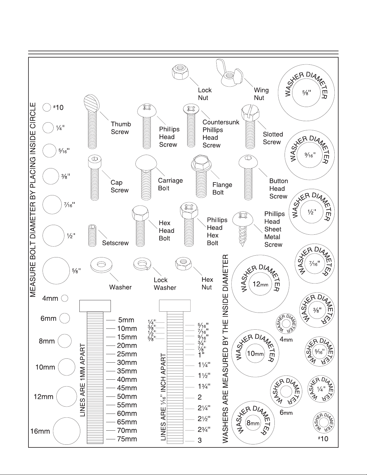
Hardware Recognition Chart
-10- G1012 18" Bandsaw
Use this chart to match up
hardware pieces during the
assembly process!
Page 13
G1012 18" Bandsaw -11-
Clean up Site Considerations
• Floor Load: Your Model G1012 18"
Bandsaw represents a moderate weight load
in a small footprint. Most commercial floors
are suitable for the Model G1012. Some residential floors may require additional build up
to support both machine and operator.
• Working Clearances: Consider existing and
anticipated needs, size of material to be
processed through each machine, and
space for auxiliary stands, work tables or
other machinery when establishing a location for your bandsaw.
• Lighting and Outlets: Lighting should be
bright enough to eliminate shadow and prevent eye strain. Electrical circuits should be
dedicated or large enough to handle amperage requirements. Outlets should be located
near each machine so power or extension
cords are clear of high-traffic areas. Observe
local electrical codes for proper installation
of new lighting, outlets or circuits.
The unpainted surfaces are coated with a waxy
oil to protect them from corrosion during shipment. Remove this protective coating with a solvent cleaner or citrus-based degreaser such as
Grizzly’s G7895 Degreaser. Avoid chlorinebased solvents as they may damage painted
surfaces should they come in contact. Always
follow the usage instructions on the product you
choose for clean up.
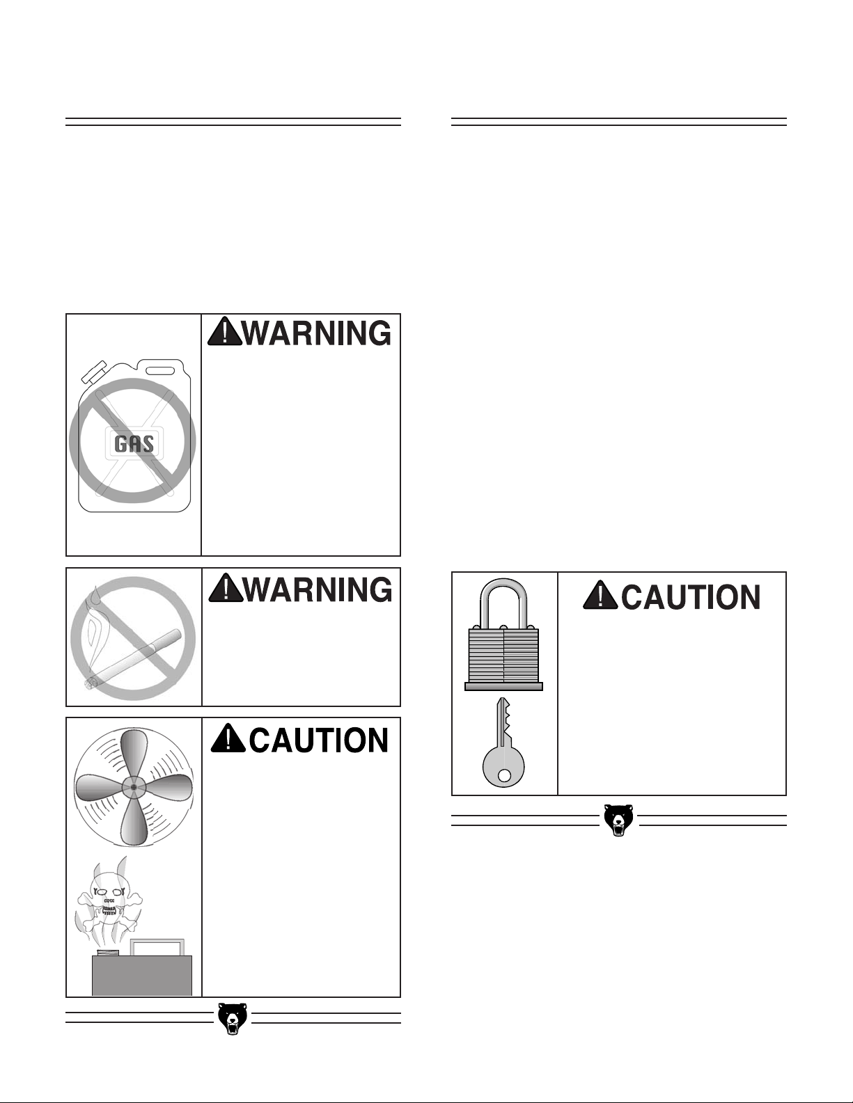
Make your shop “child safe.”
Ensure that your workplace
is inaccessible to children
by closing and locking all
entrances when you are
away. Never allow visitors in
your shop when assembling,
adjusting, or operating
equipment.
Do not use gasoline or
other petroleum-based
solvents to clean with.
They have low flash
points which make them
extremely flammable. A
risk of explosion and
burning exists if these
products are used.
Serious personal injury
may occur.
Do not smoke while using
solvents. A risk of explosion or fire exists and may
result in serious personal
injury.
Many of the solvents
commonly used to clean
machinery can be toxic
when inhaled or ingested. Always work in wellventilated areas far from
potential ignition sources
when dealing with solvents. Use care when disposing of waste rags and
towels to be sure they do
not create fire or environmental hazards.
Page 14
-12- G1012 18" Bandsaw
SECTION 4: ASSEMBLY
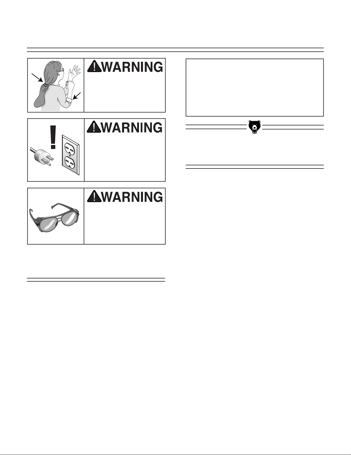
Keep loose clothing out
of the way of machinery
and keep hair pulled
back, or serious injury
may occur.
Wear safety glasses during the entire assembly
process. Failure to comply may result in serious
personal injury.
Disconnect power to the
machine when performing any maintenance or
assembly. Failure to do
this may result in serious
personal injury.
We have organized the assembly process of the
Model G1012 into steps listed below. Please follow them in sequence. The inventory photos and
lists, hardware recognition chart, parts list and
exploded diagram have been provided to make
assembly as easy as possible.
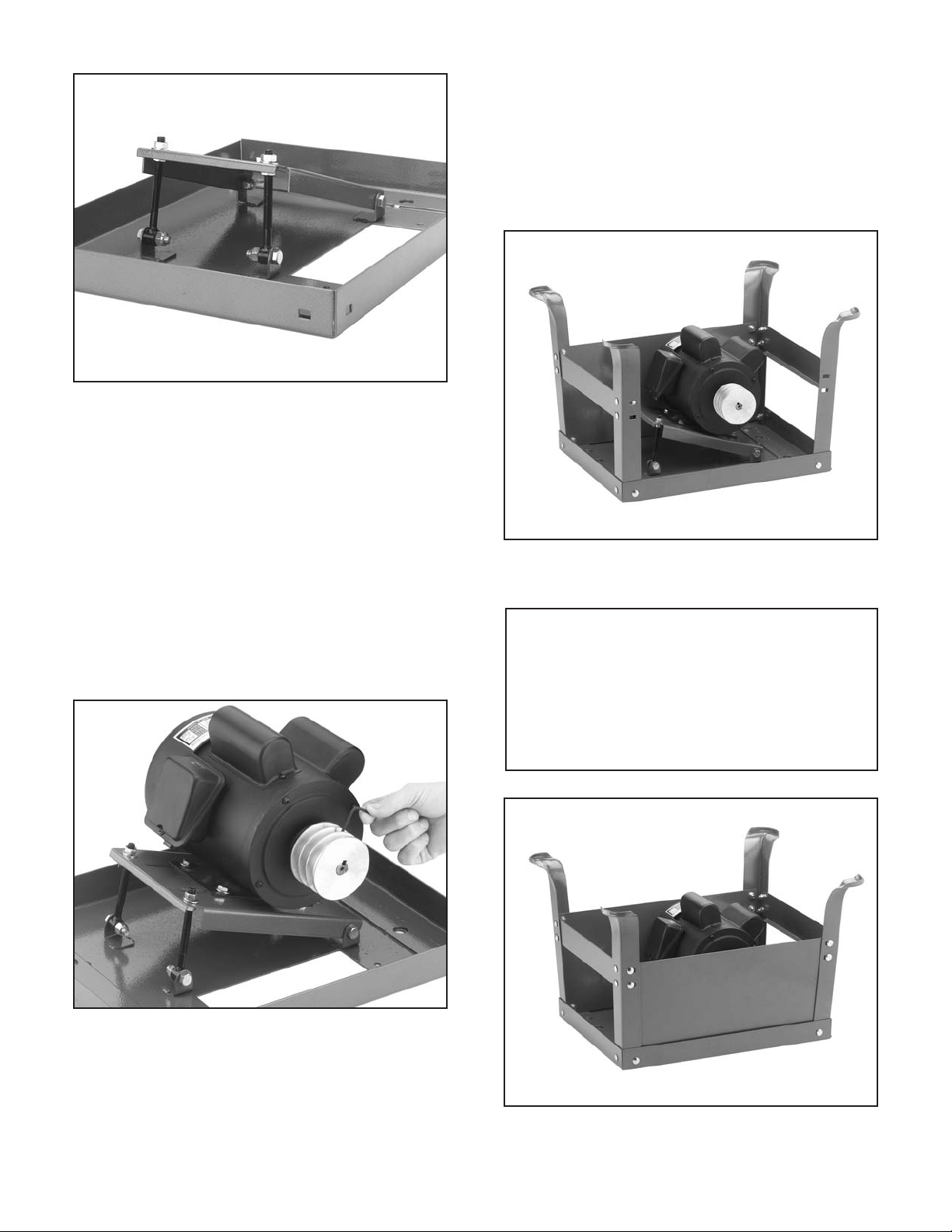
1. Stand
2. Motor
3. Mounting Unit to Stand
4. Wiring
5. Pulley Alignment
6. Table
7. Fence Assembly
8. Total Unit Check
Order of Assembly
NOTICE
TOOLS REQUIRED: In addition to the tools
provided with your bandsaw, you will need a
metric set of wrenches, large and medium
flat-tipped screwdrivers, a Phillips
®
screw-
driver, and a 6" or 8" adjustable wrench.
To begin the stand assembly, locate all the stand
parts so they are within easy reach.
1. Flip the stand top upside down. Install the
two adjustment bolts on the stand top by
placing the
3
⁄8"-16 x 11⁄4" carriage bolts
through the mounts on the stand top and
then the through eyes of the adjustment
bolts. Secure with
3
⁄8" washers and hex nuts,
but do not completely tighten.
2. Using (2)
3
⁄8"-16 x 3⁄4" carriage bolts, washers, and hex nuts; attach the motor bracket
to the mounts on the stand top without tightening.
3. Place a
3
⁄8"-16 hex nut and washer on each
adjustment bolt, then rotate the motor bracket over the adjustment bolts, and secure with
another
3
⁄8"-16 hex nut and washer so your
assembly looks like Figure 5. Again, do not
completely tighten at this time.
Stand
Page 15
G1012 18" Bandsaw -13-
4. Mount the motor onto the motor bracket.
Secure with (4)
5
⁄16" -18 x 3⁄4" hex head bolts,
washers and nuts. Hand-tighten for now.
5. Place the smallest key in the groove on the
motor shaft. Line up the key on the shaft with
the pulley keyway. Slide the motor pulley
(the small triple-grooved pulley) onto the
motor shaft. Insert one of the small
1
⁄4"-20 x
1
⁄4" setscrews in the bottom of the middle pulley groove and tighten with the included
3mm hex wrench as shown in Figure 6.
6. Attach the four legs to the top of the stand
using the
5
/16"-18 x 1/2" carriage bolts, washers and nuts provided. Do not tighten down
bolts completely at this time.
Figure 5. Motor bracket attached to stand top.
Figure 6. Securing motor pulley to motor shaft.
Figure 7. Legs, braces, and one stand side
attached to stand
Figure 8. Legs, braces, and both stand sides
assembled as an option.
7. Attach the two horizontal braces to the legs
and secure with the
5
/16"-18 x 1/2" carriage
bolts, washers and nuts provided. Attach
one of the stand sides on the opposite side
of the pulley slot in the stand top. Your
assembly should now look like Figure 7.
NOTICE
As an option, you may attach the other
stand side to the stand at this time.
Performing this step now will ease assembly of this part, but it will limit your access
to the motor pulley when installing V-belts.
Page 16

-14- G1012 18" Bandsaw
10. Flip the stand upright and adjust it back and
forth so it is level and symmetrical on the
legs. Now, tighten all of the stand bolts
(except the last stand side if you left it off) to
secure the bandsaw unit in place.
At this point, place the bandsaw on the stand.
Ensure that the bandsaw pulley shaft is positioned over the rectangular hole in the stand.
When the bandsaw is positioned on the stand,
fasten it (as shown in Figure 11) with the (4)
1
⁄2"-
12 x 1
1
⁄2" hex head bolts, washers and nuts pro-
vided. Tighten securely.
The Model G1012 can be awkward to handle
without assistance. The bandsaw unit is
also very unstable until it is permanently
mounted to the stand. Failure to use caution
during assembly could lead to serious personal injury.
Figure 11. Bandsaw unit mounted to stand.
Figure 9. Preparing rubber feet for installation.
Figure 10. Rubber foot installed.
8. Prepare the four rubber feet by placing the
5
⁄16"-18 x 1" bolts through the rubber feet and
tightening the
5
⁄16"-18 hex nuts as shown in
Figure 9.
9. Install each rubber foot on the bottom of
each leg. Thread on another
5
⁄16"-18 hex nut
to tighten the rubber foot to the leg as shown
in Figure 10.
Page 17
G1012 18" Bandsaw -15-
Figure 13. Securing wheel pulley to shaft.
Figure 12. Key in wheel pulley shaft.
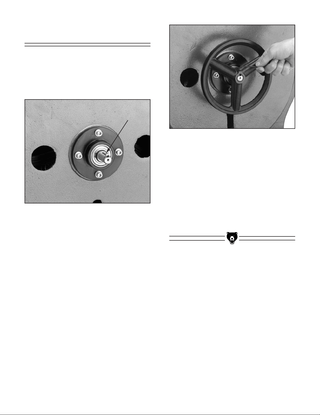
Pulleys
With the bandsaw unit mounted firmly onto the
stand, the pulleys need to be installed next.
1. Locate the upper pulley from your loose
parts. Make sure the key is in the upper pulley shaft keyway as shown in Figure 12.
2. The wheel pulley is shaped so that it must be
installed with the curved side out (look at the
side profile of the wheel pulley to determine
this shape).
3. Align the the keyway in the pulley to the key
on the shaft and insert the wheel pulley as
far as it will go on the shaft. A few taps with
a dead blow rubber hammer may be necessary to fit the wheel pulley all the way onto
the shaft.
4. Insert one of the
1
⁄4"-20 x 1⁄4" setscrews into
the wheel pulley and tighten to the shaft as
shown in Figure 13.
5. Install the stepped pulley through the opening in the bandsaw unit, directly below the
wheel pulley.
6. Thread one of the
5
⁄8"-11 hex nuts onto the
stepped pulley shaft, followed by a
5
⁄8" washer. Place this assembly through the opening
in the bandsaw unit and secure with another
washer and hex nut from inside the bandsaw
unit. Leave the last hex nut loose enough
that you can still move the stepped pulley for
further adjustments.
Page 18
-16- G1012 18" Bandsaw
5. To align pulleys, there is a variety of adjustment. For example:
A. The band wheel pulley can be slid along
the shaft.
B. The three-step pulley can be adjusted
away from the base by doubling up a
washer.
C. The motor pulley can be turned around
and repositioned on the motor shaft.
Remember, the motor should remain level
after any adjustments.
Figure 15. Pulley deflection w/moderate pressure.
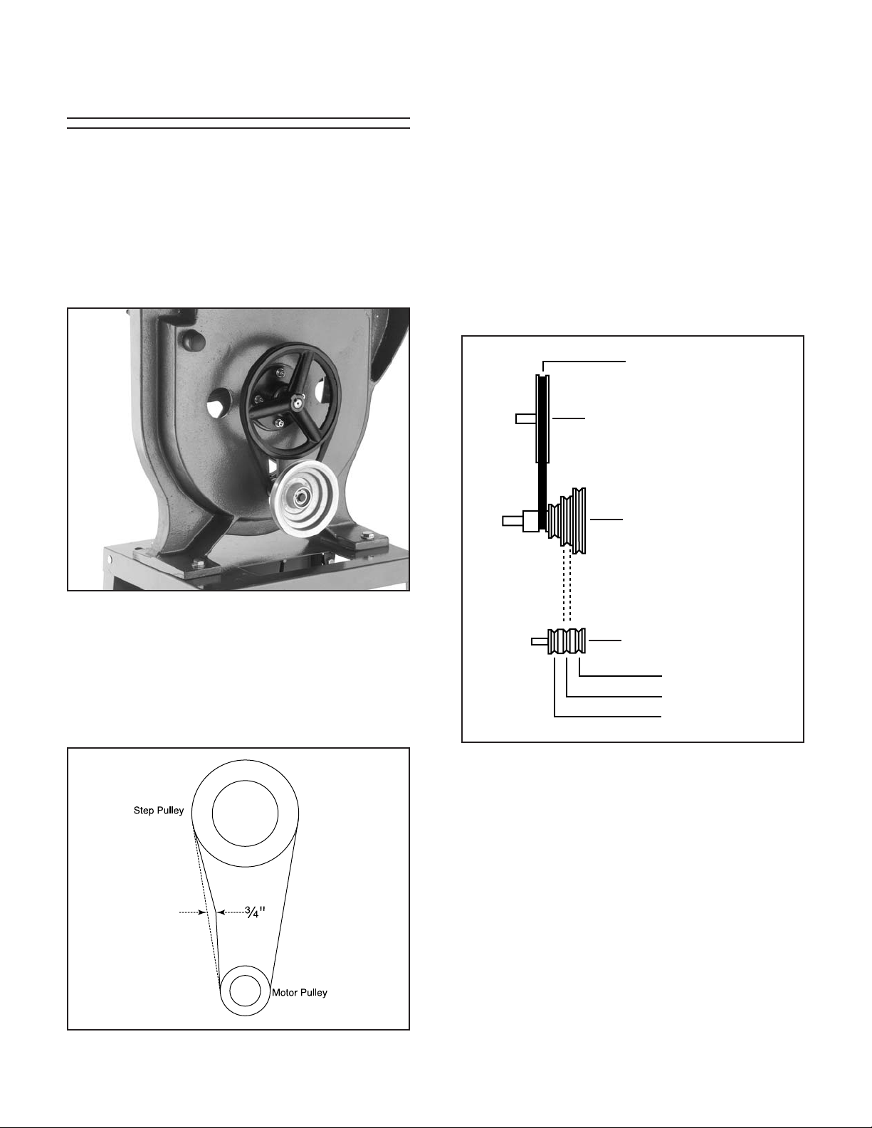
V-Belts
3. Adjust the motor back and forth until the V-
grooves line up with the V-grooves on the
three-step pulley.
4. Slip either the 31" or 33" belt over the motor
pulley and the step pulley, depending on the
desired speed. For general woodworking, we
recommend setting the lower belt for the
fastest rate of speed. See Figure 16 for
speeds.
You may have to back off the nuts on the
motor adjustment bolts to allow enough
motor swing to attach the belt.
A32 Belt
Bandsaw Pulley
Step Pulley
Motor Pulley
A33 Belt
2100 F.P.M.
A31 or A33 Belt
A31 Belt
3150 F.P.M.
2600 F.P.M.
Figure 16. Pulley speed chart.
In order to ensure proper power transmission
from motor to band wheels, the pulleys should be
aligned and the belts should have proper tension.
To begin pulley and belt assembly:
1. Place the A32 belt in the wheel pulley groove
and the last groove in the stepped pulley as
shown in Figure 14.
2. Tension the belt by pushing the stepped pulley down in the shaft slot. The belt deflection
should be approximately
3
⁄4" when you push
on the center of the belt (similar to Figure
15) with your index finger.
Figure 14. Stepped pulley installed with wheel
pulley V-belt in place.
Page 19

G1012 18" Bandsaw -17-
6. To tighten the belt from the stepped pulley to
the motor, loosen the nuts on each motor
adjustment bolt and lower the motor into
position. The weight of the motor is sufficient
for the amount of tension required. Tighten
the nuts against the motor plate, so your
assembly looks similar to Figure 17.
Belt Guard
Figure 18. Belt cover mounted to stand.
Figure 17. V-belts mounted on pulleys.
1. When all belts are installed, aligned, and
tightened, fasten the last stand side to the
stand legs. (If this has already been done,
skip this step.)
2. Place the belt cover over the pulleys on the
bandsaw unit and secure with the (2)
1
⁄4"-20
x
1
⁄2" hex bolts, (4) 1⁄4" washers, and (2) 1⁄4"20 hex nuts. Your assembly should now look
similar to Figure 18.
DO NOT operate bandsaw with cover
removed or serious personal injury may
occur!
Page 20

-18- G1012 18" Bandsaw
Always keep the tapered table pin in place
when operating the bandsaw.
To mount the table to the bandsaw unit:
1. Locate the trunnion casting from your loose
parts. The mounting bolts are already in the
table saw unit, near the lower blade guides.
Remove these bolts and their washers.
2. Line up the holes on the trunnion casting
with the roll pins that are in the bandsaw
unit.. Tap the trunnion casting down onto the
bandsaw unit. Secure with the hex bolts and
washers as shown in Figure 19.
Table
Figure 19. Trunnion casting mounted to
bandsaw unit.
Figure 21. Positive stop location/installation.
Figure 20. Table mounted on trunnion casting.
3. Using the table slot for access, remove the
table pin and guide the bandsaw table
around the blade so the blade is centered in
the table. Rotate the table 90˚ and carefully
place the table on the trunnions, so that the
threaded studs go through the holes in the
trunnions.
4. Using the two plastic knobs from your hardware bags, secure the table to the trunnions
as shown in Figure 20.
6. Fit the tapered table pin in the opening of the
access slot.
7. After verifying that the positive stop holds the
table 90˚ to the blade, set the trunnion pointer to 0˚ on the trunnion gauge.
5. The Model G1012 includes a positive stop
bolt for quick table adjustments. Locate the
3
⁄8"-16 x 3" hex bolt from your hardware bag
and thread it into the trunnion casting as
shown in Figure 21. Use a
3
⁄8"-16 hex nut
from the hardware bag to lock the bolt in
place.
Trunnion Pointer
Page 21

G1012 18" Bandsaw -19-
The last item to install is the rip fence. Notice on
the front and back edge of the table there are (4)
1
⁄4" threaded holes. These holes accept the cap
screws that secure the fence rails to the table.
This assembly is illustrated in Figure 24.
1. Attach the rear fence rail to the table with the
(4)
1
⁄2" - 20 x 2" cap screws and spacers pro-
vided.
2. If you wish to mount the fence to the left of
the blade, the fence must be mounted to the
front rail before it is attached to the table.
Otherwise, you will need to remove the
blade to slide the fence over.
3. Secure the mounting bolts and ensure that
the fence slides easily on the rails. Apply a
shot of light oil or silicone spray to each rail
for better movement. To remove the fence
from the table, reverse steps 1-3.
To install the upper and lower blade guides:
1. Locate the eight blade guides from your
hardware bags. Insert the blade guides in
the holes that face the bandsaw blade.
2. Secure the blade guides by screwing the
thumbscrews into the threaded holes that
intersect the blade guides as shown in
Figure 23.
Figure 24. Attachment of fence rail to the table.
Table
Spacer
1/4" - 20 x 11⁄2" Socket
Head Cap Screw
Fence
Blade Guides
Rail
This concludes assembly of the bandsaw.
Please DO NOT operate this saw until you
have read and have followed the safety
information, adjustment and operation sections in this manual. Operation without
complete knowledge of this machine could
lead to serious operator injury or damage to
the machine or workshop.
Figure 22. Inserting roll pin in table.
7. Install the table insert in the center of the
table. Rotate the table insert so the notch in
the insert lines up with the notch in the table
to form a small hole. Locate the roll pin from
your hardware bags and tap it into this small
hole as shown in Figure 22.
Thumbscrew
Blade Guides
Figure 23. Blade guide assembly.
Page 22
-20- G1012 18" Bandsaw
SECTION 5: ADJUSTMENTS
Keep loose clothing
rolled up and out of the
way of machinery and
keep long hair pulled
back.
Wear safety glasses during the entire adjustment
process. Failure to comply may result in serious
personal injury.
Disconnect power to the
machine when performing any maintenance or
assembly. Failure to do
this may result in serious
personal injury.
A
B
D
C
E
F
G
F
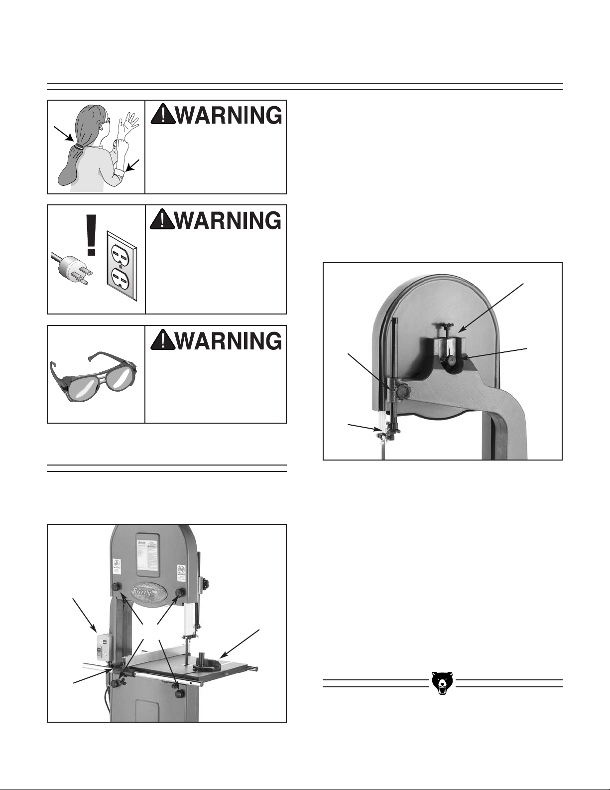
Review the bandsaw controls and locations
shown in Figures 25 & 26. The following callouts describe each control function.
Controls
Figure 25. Front controls.
A. SWITCH — Turns the bandsaw ON/ OFF.
B. FENCE LOCK — Locks/unlocks fence clamp
for adjustments.
C. MITER GAUGE — Primarily used for making
crosscuts.
D. WHEEL COVER KNOBS — These knobs
are used to attach/detach the wheel covers.
E. TENSION KNOB & GAUGE — Knob
loosens and tightens the blade tension and
is measured by the tension gauge.
F. TRACKING KNOB — Tilts the upper wheel
forward/backward.
G. BLADE GUIDE HEIGHT KNOB — Loosens
blade guide post to raise/lower blade guides
and blade guard.
H. BLADE GUIDE ASSEMBLY — Houses the
blade guides and rear support bearing.
Figure 26. Rear controls.
Page 23

G1012 18" Bandsaw -21-
Blade Tension
To adjust the tension:
1. Loosen the upper and lower guide blocks
and raise the upper guide block as high as it
will go.
3. With moderate tension already on the blade,
turn the bandsaw ON.
4. Release the tension one quarter of a turn at
a time. Do this very slowly. When you see
the bandsaw blade start to flutter, stop
decreasing the tension.
5. Now, slowly increase the tension until the
blade stops fluttering. Tighten the tension
one more quarter of a turn.
6. Look at what the tension gauge reads and
use that as a guide for tensioning your blade
in the future.
If the tension seems correct, turn the bandsaw
OFF and make the other adjustments, and test
run. If the blade does not cut properly, the tension
may be incorrect. Re-adjust the tension. New
blades often stretch with use. However, removing
the tension from the blade when not in use will
reduce stretching and extend your blade life.
Blade Tracking
There are two ways to track a bandsaw blade:
Center Tracking and Coplanar Tracking.
Center Tracking is the fastest and easiest, but not
the most precise.
Center Tracking:
1. Disconnect the bandsaw from the power
source!
2. Adjust the upper and lower guide blocks and
support bearings away from the blade.
Remove the upper wheel cover.
3. Adjust blade tension to how it will be used
during operation.
4. Loosen the tracking control lock nut. Turn
the tracking control knob clockwise/counterclockwise while turning the upper wheel by
hand until the blade stays centered on the
wheel.
5. Spin the upper wheel by hand at least three
times to ensure that the blade stays centered. If the blade does not stay centered, readjust as necessary.
6. Tighten the tracking control lock nut and
replace the upper wheel cover.
For the best performance from your saw, regularly maintain proper tracking of the blade.
For Coplanar Tracking, see the “Wheel
Alignment” instructions.
Be careful when turning the band wheels by
hand. The aluminum spokes may have
sharp edges and the blade teeth may extend
beyond the edge of the wheel.
Page 24

-22- G1012 18" Bandsaw
Figure 28. Proper guide block adjustment.
Guide-Block Holder
Guide-Blocks
Space .004" Each Side
Blade
Whenever changing a blade or adjusting tension
and tracking, the upper and lower blade support
bearings and guide-blocks must be re-adjusted.
Always loosen the thumbscrews/setscrews and
knobs and adjust the assemblies away before
installing a new blade or making blade adjustments. After blade tension and tracking are set
correctly, re-adjust the upper and lower support
bearings and guide-block assemblies into position.
UPPER BLADE GUIDE ASSEMBLIES
The guide-blocks support the blade from both
sides. The steel guide-blocks should be set .004"
from the blade as illustrated in Figure 27. The
guide-block holder should be adjusted so the
front blocks are
1
⁄16" behind the saw gullets.
To set the guide-blocks within the guideblock holder:
Blade Guides
Always disconnect
power to the machine
when making adjustments. Failure to do this
may result in serious
personal injury.
3. Note where the blade is in the guide block
holder. It should be roughly centered. If it is
not centered, loosen the hex bolt that
secures the blade guide assembly to the
guide post.
4. Rotate the guide assembly so the blade is
centered between each side of the guide
block holders.
5. Tighten the hex nut that secures the blade
guide assembly to the guide post.
Guide Post
Guide Post
Figure 27. Tension and guide post controls.
The guide post (shown in Figure 30) is adjustable
so the guide blocks will stay aligned with the
blade when the guide post is raised or lowered.
To adjust guide assembly alignment on guide
post:
1. Adjust blade tension and tracking.
2. Loosen the guide blocks in the upper and
lower guide assemblies.
1. Loosen the setscrews locking the guideblocks in the guide-block holder.
Page 25
G1012 18" Bandsaw -23-
The support bearings back-up the blade during
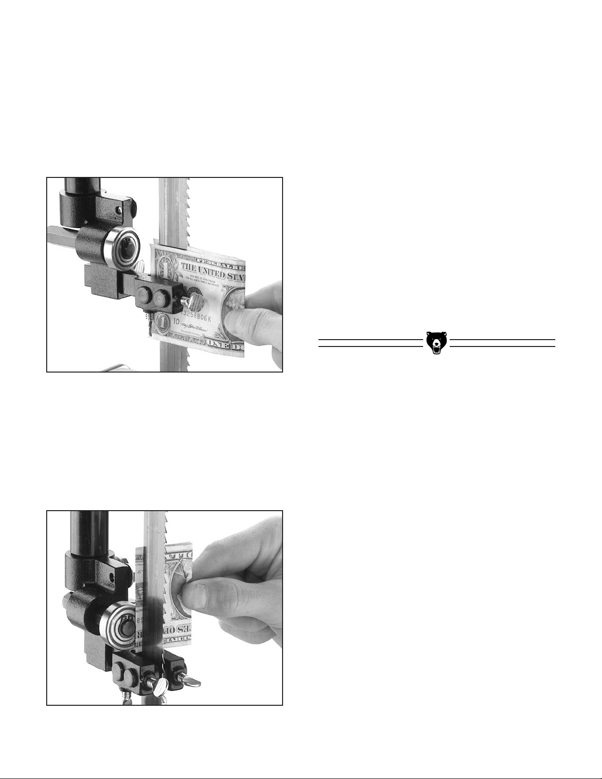
the sawing operation. To adjust the upper support bearing, loosen the shaft setscrew. The
upper blade support bearing should be adjusted
to within .016" (four thicknesses of a dollar bill)
behind the blade as shown in Figure 29.
Retighten the shaft setscrew.
LOWER BLADE GUIDE ASSEMBLIES
The lower blade guide assemblies should be
adjusted to the same tolerances as the upper
guide assemblies.
1. Adjust lower support bearing to within .016"
from the rear of the blade.
2. Adjust lower guide-blocks to .004" from
blade sides.
3. Adjust lower guide-block holder to within
1
⁄16"
behind blade gullets.
4. Secure all adjustment knobs and screws.
5. Make sure the blade tracks true. Inspect for
any blade deflection caused by incorrect
positioning of the guide blocks. The support
bearings should rotate only under load.
Figure 29. Single dollar thickness on each side
of the blade.
Figure 30. Dollar folded twice for support
bearing adjustment.
2. Clearance between the blade and the guideblocks should be .004" (similar to the thickness of a dollar bill). For an easy gauge, fold
a dollar bill in half and place each half on
each side of the blade as in Figure 28.
3. Adjust the guide blocks and lock into position
by tightening the thumbscrews. Remove the
dollar.
Page 26

-24- G1012 18" Bandsaw
The bandsaw table will tilt 5˚ left and 45˚ right
from horizontal. There is an adjustable positive
stop so the table can be reset perpendicular to
the blade after tilting to the right. To tilt the table:
1. Loosen the two plastic knobs underneath the
table as shown in Figure 31.
2. Position the table to the desired angle of tilt.
Refer to the angle gauge on the front table
trunnion for the tilting angle.
3. Retighten both plastic knobs.
Table Adjustments
Figure 31. Plastic trunnion knobs.
Blade Changes
To remove the blade:
1. Unplug the bandsaw!
2. Release tension on the blade by turning the
tension control knob counter-clockwise.
3. Remove the table insert and the table pin.
Adjust the upper and lower guide blocks
away from the blade.
4. Put on leather gloves to protect your hands
from the sharp teeth of the blade.
5. Open the upper and lower wheel covers and
slide the blade off both wheels. Use caution
— the blades are sharp!
6. Rotate the blade 90˚ so it will slide through
the slot in the table.
Always disconnect
power to the machine
when changing blades.
Failure to do this may
result in serious personal injury.
When removing or installing wide blades, it may
be convenient to completely remove the upper
and lower guide blocks. Be sure to replace them
before cutting. To replace the blade:
1. Slide the blade through the table slot, ensuring that the teeth are pointing down toward
the table.
If the teeth will not point downward in any orientation, the blade is inside-out. Put on
heavy gloves, remove the blade, and twist it
rightside-out.
Wear gloves and safety goggles when handling blades. Coiled blades spring open as
they are uncoiled and could cause deep
punctures or lacerations.
2. Slip the blade through the upper and lower
guides, and mount it over the upper and
lower wheels.
3. Apply tension, then check and adjust tracking.
4. Adjust the upper and lower guide blocks and
the support bearings.
5. Close and tighten the wheel covers.
6. Replace the table insert and table pin, being
sure not to use excessive force when inserting the table pin.
Page 27
G1012 18" Bandsaw -25-
NOTICE
If setting table tilt to the left, it will be necessary to remove the positive stop.
To adjust the positive stop so the table will be
90° to the blade:
1. Loosen the two plastic knobs and check-nut
that secure the positive stop adjusting bolt
shown in Figure 32.
2. Raise the upper blade guide assembly and
place a 6" machinist’s square or try-square
on the table next to the side of the blade.
Adjust the positive stop adjusting bolt to
raise or lower the table until the table is 90˚
to the blade.
Figure 32. Squaring table to blade.
Figure 34. Squaring table to blade back.
Figure 33. Squaring table to blade.
3. Secure the plastic knobs and lock the posi-
tive stop adjusting bolt by tightening the
check-nut. Ensure that the bolt does not turn
while tightening the check-nut.
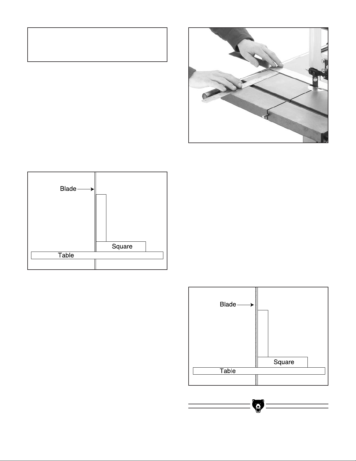
To adjust the miter slot parallel to the bandsaw blade:
1. Loosen the six trunnion bolts underneath the
table.
2. Place a good straightedge along the blade.
The straightedge should touch the front and
the back of the blade. Use a fine ruler to
gauge the distance between the blade and
the miter slot as shown in Figure 33. The
distance you measure should be the same at
both the front and the back of the table.
3. Adjust the table in the desired direction and
secure in position by retightening the trunnion bolts.
The table should also be 90˚ to the back of the
blade as shown in Figure 34. If you should find
that the table is not perpendicular to the back of
the blade, shim the table in the desired direction
by placing washers between the table and the
two trunnions.
Remove the trunnion bolts and add washers so
the table tilts in the desired direction. Electrical
washers are very thin and will allow fine adjustment.
Page 28

Fence Adjustment
Fence locking is controlled by turning the two
handles on the front of the fence. The straight
handle controls the locking clamp on the back rail
and the star knob controls the locking clamp on
the front rail. See Figure 35 for control locations.
Both of these knobs must be loosened when
moving the fence.
When adjusting your fence to the desired cutting
width, use a tape measure or a ruler to measure
the distance from the fence to the blade. Always
lock the front locking knob first.
Figure 35. Fence controls.
If your fence does not clamp square, the adjustment bolts shown in Figure 35 can be loosened
to allow you to slightly adjust the fence one way
or another. When the fence is in the desired position, tighten the bolts to lock it in place.
-26- G1012 18" Bandsaw
Front
Locking
Rear
Locking
Adjustment Bolts
Blade Lead
Most bandsaw blades will not appear to cut
straight when using the fence or miter gauge.
This is called “lead.” (See Figure 36.) Lead
occurs (1) if the blade tension is incorrect, (2) if
the teeth are dull on one side, or (3) if the teeth
are set heavier on one side of the blade than the
other.
If you notice that your blade is not cutting
straight (i.e. leading) while using the fence or
miter gauge:
1. Check that the miter slot or fence is parallel
to the blade line.
2. Check that you have proper blade tension. If
the blade tension is correct and it is not convenient to replace the blade, compensate for
lead by skewing the fence or adjusting the
table.
To skew your fence:
1. Obtain a piece of scrap wood that is approx-
imately
3
⁄4" thick x 3" wide x 17" long. On a
wide face of the board, draw a straight line
parallel to the long edge.
2. Slide the fence out of the way and cut freehand along the line. Stop at the halfway
point. Turn the bandsaw off and wait for the
blade to stop.
3. Clamp the board to the bandsaw table without moving it. Now slide the fence over to
the board so it barely touches one end of the
board.
4. Loosen the two skewing cap screws on top
of the fence. Figure 35.
5. Skew the fence left or right so it is parallel to
the edge of the scrap piece. You may need
to readjust the fence locking mechanisms to
gain maximum adjustment.
6. While maintaining the skew, tighten the cap
screws.
Page 29

G1012 18" Bandsaw -27-
Figure 36. Blade leading away from line of cut.
To compensate for lead if making straight
crosscuts using the miter gauge, you will
need to shift the table. To do this:
1. On a scrap piece of wood, mark a line that is
perpendicular to the front edge. Starting
where the line begins, cut the board by pushing it through the blade with the miter gauge.
2. Loosen the table mounting bolts according to
the instructions about “Table Adjustments”
on page 20. Shift the table to compensate
for the blade lead.
3. Repeat steps 1 and 2 until the blade cuts
straight when wood is pushed through with
the miter gauge.
NOTICE
Lead adjustments will change when new
blades are mounted on the saw.
NOTICE
If the table is shifted, the fence will be
affected since it is attached.
Wheel Alignment
Wheel alignment is one of the easiest ways to
ensure you get optimal performance from your
bandsaw. When wheels are aligned, or coplanar,
the bandsaw is more likely to cut straight without
wandering; and vibration, heat, and blade wear
are considerably decreased because the blade is
automatically balanced on the wheel. This is
known as “Coplanar Tracking.”
To verify if the the upper and lower wheels are
coplanar:
1. With the blade on and properly tensioned,
hold a straightedge close to the center of
both wheels. Make sure it fully extends
across them as shown in Figure 37.
Figure 37. Checking wheel alignment with a
straightedge.
2. A perfectly coplanar set of wheels will allow
the straightedge to touch the top and bottom
of the outside rims on each wheel. If this is
the case with your wheels, then they are
coplanar.
3. If your wheels are not coplanar, check them
for adjustment by placing the straightedge
on the lower wheel first – ensuring that it
touches both the top and bottom rim – and
adjust the tracking knob to see how the
straightedge lines up with the upper wheel.
Page 30

-28- G1012 18" Bandsaw
Figure 39. Coplanar diagram.
Figure 38. Measuring wheel difference.
4. Replace the wheel, any remaining washers,
and the securing nut. Tighten the blade as it
will be used during operation before you
check the wheels for being coplanar. Often
the wheels may be coplanar with the blade
loose, then be pulled out of alignment when
it is tightened.
5. The first time you get the wheels coplanar,
place a mark on each wheel where you held
the straightedge. This assures repeated
accuracy every time you adjust your wheels.
When wheels are properly coplanar, the blade
may not be centered on the crown of the wheel,
but it will be balanced. See Figure 39 to better
understand coplanarity.
2. Remove the blade from the saw, then
remove the securing nut and the washers
from the wheel that needs to be shimmed.
Take the wheel off.
3. Electrical washers work well for shimming
because they are offered in a wide range of
thicknesses. Measure how many you will
need and place them on the mounting shaft.
If the straightedge will not touch the top and bottom rim of the upper wheel evenly, first determine
if the upper wheel needs to be moved forward or
backward. You can only shim the wheels to come
forward.
• If the front wheel is behind the straightedge
then the front wheel can be shimmed.
• If the front wheel is comes forward from the
plane of the lower wheel, the lower wheel
needs to be shimmed forward, so the
straightedge lines up even with both wheels.
Shimming a wheel:
1. Adjust the tracking knob so the top wheel is
parallel with the bottom wheel. With the
straightedge touching both points of the
wheel that does not need to be adjusted,
measure the distance away from the incorrect wheel with a fine ruler. See Figure 38.
The distance you measured with the ruler is
the distance the wheel must be corrected.
Page 31

G1012 18" Bandsaw -29-
Once the assembly is complete and the adjustments are done to your satisfaction, you are
ready to test the machine.
Turn on the power supply at the main panel. Pull
the paddle switch up to start the bandsaw. Make
sure that your hand is poised over the switch in
case there is a problem. The bandsaw should run
smoothly with little or no vibration or rubbing noises. Strange or unnatural noises should be investigated and corrected before operating the
machine further.
If you cannot easily locate the source of an
unusual noise or vibration, feel free to contact our
service department for help.
Test Run
SECTION 6: OPERATIONS
Keep loose clothing
rolled up and out of the
way of machinery and
keep hair pulled back.
Wear safety glasses during the entire operation
process. Failure to comply may result in serious
personal injury.
Disconnect power to the
machine when performing any maintenance or
assembly. Failure to do
this may result in serious
personal injury.
Overview
The bandsaw is one of the most versatile wood
cutting tools in the shop. It is capable of performing many different cutting functions including, but
not limited to:
STRAIGHT CUTS
• Miters
• Angles
• Compound Angles
• Resawing
• Ripping
• Crosscutting
IRREGULAR CUTS
• Simple and Complex Curves
• Duplicate Parts
• Circles
• Beveled Curves
NOTICE
The following section was designed to give
instructions on the basic operations of this
bandsaw. However, it is in no way comprehensive of every bandsaw application. There
are many different jigs that can be built to
increase safety, accuracy, and types of cuts.
WE STRONGLY RECOMMEND that you read
books, trade magazines, or get formal training to maximize the potential of your
machine.
Using this machine produces sawdust which may
cause allergic reactions
and respiratory problems.
Use an approved dust
mask to protect yourself
from these hazards!
Page 32

-30- G1012 18" Bandsaw
Do not force the material against the blade, use
light and even pressure. Light contact with the
blade will permit easier line following and prevent
undue friction, heat and work-hardening along
the back edge of the blade.
Avoid trying to turn sharp corners because this
will twist the blade. Remember, you must saw
around corners.
NOTICE
Set the top guide assembly so it is just
above the top of the work at all times.
Blade Information
Although you can perform many types of straight
cuts such as angling and mitering on the bandsaw, they will not be as precise as on a table saw.
Also, since the blade is flexible, the resulting cut
is somewhat rougher than one performed on a
table saw. However, just as a table saw is suited
to precision straight cuts and miters, the bandsaw
excels when resawing and when cutting irregular
shapes. A properly adjusted and tuned up bandsaw is also safer to operate than most other saws
and is capable of performing many sawing functions with ease and accuracy.
A common fault when using a bandsaw is blaming the saw for not performing up to expectations.
Many factors contribute to the performance of a
bandsaw. Using the wrong kind of blade for the
job or using a poor quality blade will result in
unsatisfactory performance. Misuse of the saw or
using incorrect sawing techniques can be unsafe
as well as result in frustration and poor cuts.
Remember, the blade does the cutting with the
operator’s guidance. Replace and clean blades
as necessary and make adjustments periodically
to keep the saw always running in top condition.
Selecting the right blade requires a combination
of the various blade characteristics mentioned
below, the type of material you plan to cut, and
the type of cut you are going to perform.
Blade Length
Measured by the circumference, blade lengths
are usually unique to the brand of your bandsaw
and the wheel diameter. The Model G1012 is
designed for blades that are 124" long. However,
the tension adjustment will accommodate blades
up to a maximum length of 125" and down to a
minimum of approximately 123" in length.
Blade Width
Measured from the the back of the blade to the tip
of the blade tooth (the widest point), blade width
is often the first consideration given to blade
selection.
A narrow blade can cut tight curves (a small
radius) but is not very good at cutting straight
lines, because they naturally wander (blade
lead). However, larger blades are much better at
cutting straight lines, but function poorly at cutting
small curves because of their size.
The Model G1012 functions best with
1
⁄4",3⁄8",1⁄2",
1" and 1
1
⁄2" widths. Refer to the current Grizzly
catalog for prices and ordering information.
Always pick the size of blade that best suits your
application.
Tooth Style
When selecting blades, another option to consider is the shape, gullet size and angle of the teeth
— otherwise known as “Tooth Style.”
Figure 40 shows the three main categories of
tooth style:
Page 33

G1012 18" Bandsaw -31-
• RAKER — This style is considered to be the
standard because the tooth size and shape
are the same as the tooth gullet. The teeth
on Raker blades usually are very numerous,
have no angle, and produce cuts by scraping
the material; these characteristics result in
very smooth cuts, but at the same time do
not cut fast and generate more heat while
cutting.
• SKIP — This style is similar to a raker blade
that is missing every other tooth. Because of
the design, skip toothed blades have a much
larger gullet than raker blades, and therefore, cut faster and generate more heat.
However, these blades also leave a rougher
cut than raker blades.
• HOOK — The teeth on this style have a positive angle (downward) which makes them
dig into the material, and the gullets are usually rounded for easier waste removal.
These blades are excellent for the tough
demands of resawing and ripping thick material.
Tooth Pitch
Usually measured as T.P.I. (teeth per inch), tooth
pitch determines the size of the teeth. More teeth
per inch (fine pitch) will cut slower, but smoother;
while fewer teeth per inch (coarse pitch) will cut
rougher, but faster. As a general rule, choose
Figure 40. Raker, Skip & Hook tooth styles.
Raker
Skip
Hook
blades that will have at least three teeth in the
material at all times. Use fine pitched blades on
harder woods and coarse pitched blades on softer woods.
Blade Care
A bandsaw blade is a delicate piece of steel that
is subjected to tremendous strain. You can obtain
longer use from a bandsaw blade if you give it fair
treatment and always use the appropriate feed
rate for your operation.
Be sure to select blades with the proper width,
style, and pitch for each application. The wrong
choice of blades will often produce unnecessary
heat which will shorten the life of your blade.
A clean blade will perform much better than a
dirty blade. Dirty blades pass through the cutting
material with much more resistance than clean
blades. This extra resistance also causes unnecessary heat.
Blade Breakage
Many conditions may cause a bandsaw blade to
break. Blade breakage is unavoidable, in some
cases, since it is the natural result of the peculiar
stresses that bandsaw blades are subjected to.
Blade breakage is also due to avoidable circumstances. Avoidable breakage is most often the
result of poor care or judgement on the part of the
operator when mounting or adjusting the blade or
support guides.
The most common causes of blade breakage are:
(1) faulty alignment and adjustment of the guides,
(2) forcing or twisting a wide blade around a curve
of short radius, (3) feeding too fast, (4) tooth dullness or absence of sufficient set, (5) excessive
tension, (6) top blade guide assembly set too high
above the work piece, (7) using a blade with a
lumpy or improperly finished braze or weld and
(8) continuously running the bandsaw when not in
use.
Page 34

-32- G1012 18" Bandsaw
Ripping
Crosscutting
Ripping is the process of cutting with the grain of
the wood stock. For plywood and other
processed wood, ripping simply means cutting
down the length of the workpiece.
To rip with the Model G1012:
1. Using a straightedge or other accurate
guide, lightly pencil the workpiece along the
desired path of cut.
2. Place the workpiece even along the fence
and line up the penciled mark with the blade,
having the blade kerf on the waste portion
side of the workpiece. Lock the front and
back of the fence in place.
3. Making sure all safety precautions have
been taken, start the bandsaw. Slowly feed
the workpiece into the blade and continue
with the cut until the blade is completely
through the workpiece. Figure 41 shows a
typical ripping operation. When cutting narrow pieces, use a push stick to protect your
fingers.
Figure 41. Ripping with a push stick.
NEVER place fingers or hands in the line of
cut. In the event that something unexpected
happens, your hands or fingers may be
pulled into the blade. ALWAYS use a push
stick when ripping narrow pieces. Failure to
follow these warnings may result in serious
personal injury!
Crosscutting is the process of cutting across the
grain of wood. For plywood and other processed
wood, crosscutting simply means cutting across
the width of the material.
To crosscut with the Model G1012:
1. Using a straightedge or other accurate guide
and lightly pencil the workpiece along the
desired path of cut.
2. Move the fence out of the way. Place the
workpiece evenly against the miter gauge.
3. Line up the penciled mark with the blade,
having the blade kerf poised to cut through
the waste portion of the workpiece.
4. After all safety precautions have been met,
start the bandsaw. Slowly feed the workpiece into the blade and continue the cut
until it is all the way through the workpiece.
Figure 42 shows a typical crosscutting operation.
Page 35

G1012 18" Bandsaw -33-
Figure 43. Resawing lumber.
1. The bandsaw must be adjusted correctly.
See Section 5: Adjustments.
2. The table must be square to the blade.
3. Use the widest blade available. The blade
must also be in good condition.
4. Use a fence to guide the work.
5. Draw a reference line on the edge of the
board.
6. Support the ends of the board if necessary.
7. Feed the workpiece slowly and evenly.
Resawing (Figure 42) is the process of cutting a
board into two or more thinner boards. The maximum board width that can be resawn is limited
by the maximum cutting height of the bandsaw.
Maximum cutting height for this bandsaw is 9
1
⁄2".
The Model G1012 18" Bandsaw is capable of
resawing, provided the saw is set up properly.
Use common sense when resawing. Attempting
to resaw too wide or too dense of a board may
put excessive strain on the blade and be dangerous.
The important consideration when resawing is
blade selection. Generally, the wider blade, the
better. In most applications, a hook or a skip tooth
style will be desirable. Also, since most resawn
lumber will be planed smooth, you should choose
blades with fewer teeth-per-inch (from 3 to 6).
While blades with fewer teeth-per-inch produce
rougher cuts, these types of blades offer larger
gullet capacities for clearing sawdust. They also
produce less heat buildup and yield more horsepower per tooth.
Resawing
Figure 42. Crosscutting with miter gauge.
Page 36

-34- G1012 18" Bandsaw
Stacked Cuts
To complete a stacked cut:
1. Align your pieces from top to bottom to
ensure that each piece has adequate scrap
to provide a clean, unhampered cut.
2. Secure all the pieces together in a manner
that will not interfere with the cutting. Hot
glue on the edges works well, as does brad
nails through the waste portion. (Be careful
not to cut into the brads!)
3. On the face of the top piece, lay out the
shape you intend to cut.
4. Make relief cuts perpendicular to the outline
of your intended shape in areas where
changes in blade direction could strain the
woodgrain or cause the blade kerf to bind.
5. Cut the stack of pieces as though you were
cutting a single piece. Follow your layout line
with the blade kerf on the waste side of your
line as shown in Figure 44.
Cutting Curves
When cutting curves, simultaneously feed and
turn the stock carefully so that the blade follows
the layout line without being twisted. If a curve is
so abrupt that it is necessary to repeatedly back
up and cut a new kerf, use either a narrower
blade or a blade with more T.P.I. A blade with
more T.P.I. can cut relatively tighter radii, though
the cut is usually rougher than cuts produced by
a blade with a medium amount of T.P.I.
Always make short cuts first, then proceed to the
longer cuts. Relief cuts will also reduce the
chance that the blade will be pinched or twisted.
Relief cuts are cuts made through the waste portion of the workpiece and are stopped at the layout line. As you cut along the layout line, waste
wood is released from the workpiece, alleviating
any pressure on the back of the blade. Relief cuts
also make backing the workpiece out easier, if
needed.
NOTICE
The table below lists blade widths and corresponding minimum radii each blade will
cut.
Width Radius
3
⁄8'' ..............................11⁄2''
1
⁄2'' ..............................21⁄2''
3
⁄4'' ..............................51⁄2''
1'' ................................6''
1
1
⁄2'' ............................8''
One of the benefits of a bandsaw is its ability to
cut multiple copies of a particular shape by stacking a number of workpieces together.
Before making stacked cuts, it is essential to
ensure that both the table and the blade are properly adjusted to 90°. Otherwise, any error will be
compounded with each piece cut from the top to
the bottom of the stack.
Cutting into brad nails that are used to
secure the multiple pieces can cause the
blade to brake and may cause an injury to
the operator. Be extremely careful of where
you are cutting when performing this operation.
Figure 44.
Cutting multiple pieces at once.
Page 37

G1012 18" Bandsaw -35-
SECTION 7: MAINTENANCE
V-Belts
To ensure optimum power transmission from the
motor to the blade, the V-belt must be in good
condition and operate under proper tension. The
belts should be checked for cracks, fraying and
wear. Belt tension should be checked at least
every 3 months — more often if the bandsaw is
used daily.
The V-belt is accessed via the bottom cover:
1. Push the center of the V-belt.
2. Note the amount of deflection. Deflection
should be approximately
3
⁄4". See “V-Belt
Adjustment” instructions to adjust.
The table and other non-painted surfaces on the
Model G1012 should be protected against rust
and pitting. Wiping the saw clean after every use
ensures that wood dust is not allowed to trap
moisture against bare metal surfaces.
The table can be kept rust-free with regular applications of products like Boeshield
®
T-9. For long
term storage you may want to consider products
like Kleen Bore's Rust Guardit™. See the current
Grizzly catalog for more on these products.
Table
Sealed and pre-lubricated ball bearings require
no lubrication for the life of the bearings. All bearings are standard sizes, and replacements can
be purchased from our parts department or bearing supply store.
As for other items on this machine, such as
adjustment controls, an occasional “shot” of light
oil is just about all that is necessary. Before
applying, however, wipe off any sawdust with a
clean cloth, towel or dry paint brush, and spray on
the lubricant. Ensure that oil does not get on the
pulleys or V-belt because it could cause belt deterioration and slipping.
Lubrication
Always be aware of the condition of your bandsaw. Routinely check the condition of the following items and repair or replace as necessary:
• Loose mounting bolts
• Worn switch
• Worn or damaged blade
• Worn or damaged support bearings or guide
bearings
Miscellaneous
Always disconnect
power to the machine
when making adjustments. Failure to do this
may result in serious
personal injury.
Page 38

-36- G1012 18" Bandsaw
Page 39

G1012 18" Bandsaw -37-
The following pages contain general machine
data, parts diagrams/lists, troubleshooting guide
and Warranty/Return information for your Model
G1012 18" Bandsaw.
If you need parts or help in assembling your
machine, or if you need operational information,
we encourage you to call our Service
Department. Our trained service technicians will
be glad to help you.
If you have comments dealing specifically with
this manual, please write to our Bellingham,
Washington location using the address in the
General Information section. The specifications,
drawings, and photographs illustrated in this
manual represent the Model G1012 as supplied
when the manual was prepared. However, due to
Grizzly’s policy of continuous improvement,
changes may be made at any time with no obligation on the part of Grizzly.
We have included some important safety measures that are essential to this machine’s operation. While most safety measures are generally
universal, Grizzly reminds you that each workshop is different and safety rules should be considered
as they apply to your specific situation.
We recommend you keep a copy of our current
catalog for complete information regarding
Grizzly's warranty and return policy. If you need
additional technical information relating to your
machine, or if you need general assistance or
replacement parts, please contact the Service
Department listed in the General Information
section.
Additional information sources are necessary to
realize the full potential of your machine. Trade
journals, woodworking magazines, and your local
library are good places to start.
SECTION 8: CLOSURE
Like all power tools, there is danger associated with the Model G1012 18" Bandsaw.
Use the tool with respect and caution to
lessen the possibility of mechanical damage or operator injury. If normal safety precautions are overlooked or ignored, serious
personal injury may occur.
The Model G1012 was specifically designed
for wood cutting operations. DO NOT MODIFY AND/OR USE THIS BANDSAW FOR ANY
OTHER PURPOSE. Modifications or improper use of this tool will void the warranty. If
you are confused about any aspect of this
machine, DO NOT use it until all your questions are answered. Serious personal injury
may occur.
Operating this equipment has the potential
for flying debris to cause eye injury. Always
wear safety glasses or goggles when operating equipment. Everyday glasses or reading glasses only have impact resistant lenses, they are not safety glasses. Be certain
the safety glasses you wear meet the appropriate standards of the American National
Standards Institute (ANSI).
Page 40

-38- G1012 18" Bandsaw
Customer Service #: (570) 546-9663 • To Order Call: (800) 523-4777 • Fax #: (800) 438-5901
GRIZZLY MODEL G1012 18" BANDSAW
MACHINE DATA
SHEET
Design Type:......................................................................................................Floor Model
Overall Dimensions:
Table ....................................................................................................18" x 18" x 1
1
⁄2"
Height from Floor to Table........................................................................................38"
Height Overall ..........................................................................................................71"
Width Overall............................................................................................................33''
Depth Overall............................................................................................................26''
Shipping Weight ................................................................................................350 lbs.
Weight in Place ................................................................................................266 lbs.
Crate Size ..............................................................................................18" x 26" x 60"
Foot Print ..................................................................................................24
1
⁄2" x 201⁄2"
Cutting Capacity:
Left of Blade ..........................................................................................................17
3
⁄8"
Height ......................................................................................................................10"
Table Tilt ......................................................................................................5° L 45° R
Construction:
Table ..................................................................................Precision Ground Cast Iron
Body ................................................................................................................Cast Iron
Wheels ............................................Fully Balanced Cast Aluminum with Rubber Tires
Rip Fence ..................................Double Lock, Adjustable, Extruded Aluminum Guide
Wheel Covers....................................................................................Pre-Formed Steel
Blade Guides..........................................Steel Blocks With Rear Ball Bearing Support
Motor:
Type ............................................................................TEFC Capacitor Start Induction
Horsepower..........................................................................................................2 H.P.
Phase ⁄ Cycle ..............................................................................Single Phase ⁄ 60 Hz
Switch ................................................220V Magnetic w/ Thermal Overload Protection
Voltage ..................................................................................110/220V-prewired 220V
Amps ..................................................................................................................12 / 24
R.P.M. ....................................................................................................................3450
Bearings ....................................................Shielded and Permanently Lubricated Ball
Blade:
Sizes Available ................................................................................................
1
⁄8" - 11⁄4"
Standard Blade Length ..........................................................................................124"
Blade Speeds ..................................................2100 F.P.M., 2600F.P.M., 3150 F.P.M.
Accessories:
....................................................................Includes: Fence, Miter Gauge & 1" Blade
Specifications, while deemed accurate, are not guaranteed.
Page 41

G1012 18" Bandsaw -39-
Page 42

-40- G1012 18" Bandsaw
Page 43

G1012 18" Bandsaw -41-
Page 44
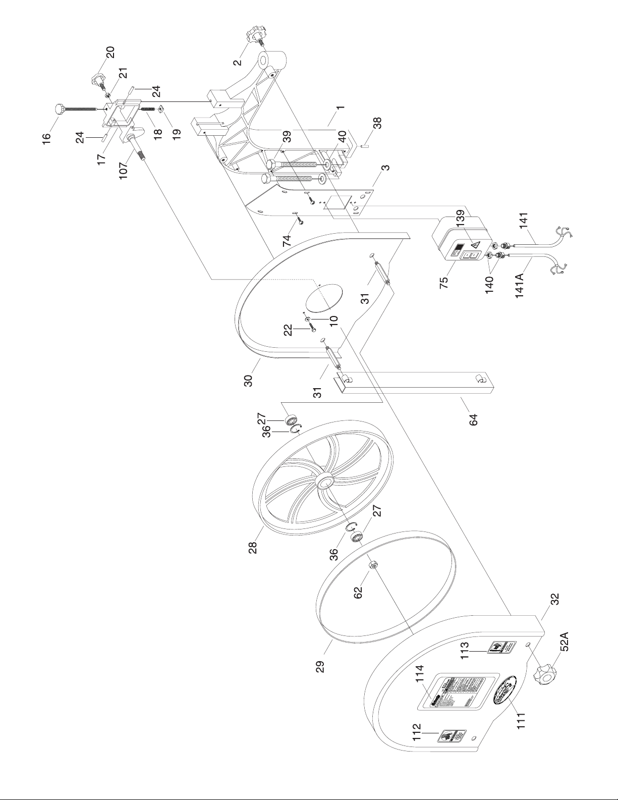
-42- G1012 18" Bandsaw
Page 45

G1012 18" Bandsaw -43-
REF PART # DESCRIPTION REF PART # DESCRIPTION
001 P1012001 UPPER FRAME ARM
002 P1012002 LOCK KNOB
003 P1012003 SWITCH PLATE
004 P1012004 GUIDE POST
005 P1012005 SUPPORT BRACKET
7
⁄8" I.D.
06A P1012006 THUMB SCREW
1
⁄4"-20 X 3⁄8"
007 P1012007 GUIDE BLOCK HOLDER
008 P1012008 ROUND GUIDE BLOCK
009 PB51 HEX BOLT
1
⁄4"-20 X 3⁄8"
010 PW06 FLAT WASHER
1
⁄4"
011 PB05 HEX BOLT
1
⁄4"-20 X 3⁄4"
012 P1012012 GUARD PLATE
013 P1012013 HEX SHAFT
014 P6200 BALL BEARING 6200
015 PR01M EXT RETAINING RING 10MM
016
P1019Z033 BLADE ADJUSTING SCREW
017 P1012017 UPR WHEEL SLIDING BRKT
018 P1012018 SPRING
019 P1019017 SQUARE NUT
3
⁄8"-16
020 P1019018 ADJUSTMENT KNOB
021 PN02 HEX NUT
5
⁄16"-18
022 PB51 HEX BOLT
1
⁄4"-20 X 3⁄8"
024 P1019021 STEEL PIN
025 PRP16M ROLL PIN 3 X 25
027 P6202 BALL BEARING 6202ZZ
028 P1012028 UPPER WHEEL
029 P1012029 WHEEL PROTECTOR
030 P1012030 UPPER WHEEL GUARD (IN)
031 P1012031 STUD
032 P1012032 UPPER WHEEL GUARD (O)
033 PB41 HEX BOLT
1
⁄2"-12 X 11⁄2"
034 PW01 FLAT WASHER
1
⁄2"
035 PN06 HEX NUT
1
⁄2"-12
036 PR21M INT. RETAINING RING 35MM
037 PW06 FLAT WASHER
1
⁄4"
038 P1012038 PIN
039 P1012039 HEX BOLT 5/8"-11 X 2
1
⁄2"
040 PW14 FLAT WASHER
5
⁄8"
041 P1012041 BASE
41A
P1012041A BEARING HOUSING
042 PN04 HEX NUT
5
⁄8"-11
044 P1012044 TABLE INSERT
45A PRP44M ROLL PIN 3 X 10
046 P1012046 TAPERED PIN
047 P1012047 TABLE
048 PB35 HEX BOLT
3
⁄8"-16 X 21⁄2"
049 P1012049 TRUNNION CLAMP SHOE
050 P1012050 TRUNNION
051 P1012051 TRUN SUPPORT BRACKET
052 P1012052 LOCK KNOB FOR TABLE
52A
P1012052A COVER KNOB
053 P1012053 INDICATOR
054 P1012054 GAUGE
55A PB06 HEX BOLT
5
⁄16"-16 X 2"
056 P1012056 HEX BOLT
3
⁄8"-16
057 PN08 HEX NUT
3
⁄8"-16
058 PW02 FLAT WASHER
3
⁄8"
059 PB05 HEX BOLT
1
⁄4"-20 X 3⁄4"
061 P1012061 LOWER SUPPORT BRACKET
062 PN01 HEX NUT
1
⁄2"-20
063 P1012063 LOWER WHEEL SHAFT
064 P1012064 BLADE COVER
065 PK35M KEY 5 X 5 X 20
066 P6205 BALL BEARING 6205
067 PR01M EXT RETAINING RING 25MM
068 P1012068 LOWER WHEEL
069 P1012069 SPECIAL LEFT-HAND NUT
070 P1012070 LARGE PULLEY
072 PVA32 V-BELT A-32
074 P1012074 PAN HEAD SCREW
Page 46

-44- G1012 18" Bandsaw
REF PART # DESCRIPTION REF PART # DESCRIPTION
075 P1012075 SWITCH
076 P1012076 MOTOR
76A P1012076A CAPACITOR COVER
76C PC400S CAPACITOR
078 PK23M KEY 5 X 5 X 25
079 PSS11 SET SCREW
1
⁄4"-20 X 1⁄4"
080 P1012080 PULLEY GUARD
81A PS04 PHLP HD SCR
082 P1012082 STAND FOOT
083 PCB02 CARRIAGE BOLT
5
⁄16"-18 X 1⁄2"
084 P1012084 ADJUSTING PLATE – LONG
085 P1012085 ADJUSTING PLATE – SHORT
086 P1012086 STAND
087 PW07 FLAT WASHER
5
⁄16"
088 PN08 HEX NUT
5
⁄16" - 18
089 P1012089 MOTOR BASE
090 PB03 HEX BOLT
5
⁄16"-18 X 1"
091 P1012091 SHAFT
092 P1012092 HOLDER BASE
093 PB24 HEX BOLT
3
⁄8"-16 X 11⁄4"
094 P1012094 ADJUSTING ROD
095 P1012094 PULLEY
096 PR21M INT RETAINING RING 35MM
98A PVA31 V-BELT A-31
98B PVA33 V-BELT A-33
099 PW14 FLAT WASHER
5
⁄8"
100 PN04 HEX NUT
5
⁄8" - 11
101 P1012101 FENCE RAIL
102 P1012102 FENCE RAIL SPACER
103A PSB62 CAP SCREW
1
⁄4"-20 X 11/2"
106 P1012106 LOWER WHEEL GUARD
107 P1012107 UPPER HINGE ASSEMBLY
108 P1012108 LOWER BEARING HOUSING
110 P1012110 RAIL PLUG
111 PLABEL-8 GRIZZLY LOGO PLATE
112 P1073171 DO NOT OPEN LABEL
113 P1073170 HANDS/BLADE LABEL
114 P1012114 WARNING/ID LABEL
115 PTS006 THUMB SCREW
1
⁄4"-20 X 3⁄4"
117 PLN01 LOCK NUT
3
⁄8-16
118 P1012118 MITER GAUGE HANDLE
119 P1012119 SPECIAL WASHER
120 PS18 PHLP HD SCR 10-24 X
1
⁄4"
121 P1012121 INDICATOR
122 P1012122 GAUGE BAR
125 P1012125 PIN
126 P1012126 GAUGE BODY
127 PN08 HEX NUT
3
⁄8"
128
P4186Z308 REAR LOCK KNOB
129
P4186Z310 FRONT LOCK KNOB
130
P4186Z309 FRONT FENCE CLAMP
131
P4186Z306 CLAMP ROD
132
P4186Z303 REAR CLAMP
133
P4186Z301 ROLL PIN
134
P4186Z302 REAR FENCE BRACKET
135 PW06 FLAT WASHER
1
⁄4"
136 PB19 HEX BOLT
1
⁄4"-20 X 1⁄2"
137
P4186Z300 FENCE
138 P1012138 LOWER PULLEY
139
P4186Z206 ELECTRICITY WARNING
140 P1012140 STRAIN RELIEF
141 P1012141 POWER CORD
141A P1012141A MOTOR CORD
143 PS06 PHLP HD SCR 10-24 X 3⁄8"
144 P1012144 CORD CLIP
145 PB03 HEX BOLT
5
⁄16"-18 X 1"
146 P1012146 RUBBER FEET
147 PRP52M ROLL PIN 6 X 16MM
Page 47

G1012 18" Bandsaw -45-
TROUBLESHOOTING
Motor will not start. 1. Low voltage. 1. Check power line for proper voltage.
2. Open circuit in motor or loose 2. Inspect all lead connections on motor for loose or open
connections. connections.
Motor will not start; fuses or circuit 1. Short circuit in line cord or plug. 1. Inspect cord or plug for damaged insulation and
breakers blow. shorted wires.
2. Short circuit in motor or loose 2. Inspect all connections on motor for loose or shorted
connections. terminals or worn insulation.
3. Circuit Overloaded. 3. Reduce load on circuit.
Motor fails to develop full power 1. Power line overloaded with lights, 1. Reduce load on power line.
(power output of motor decreases appliances, and other motors.
rapidly with decrease in voltage at 2. Undersized wires or circuits too long. 2. Increase wire sizes or reduce length of wire.
motor terminals). 3. General overloading of power 3. Request a power check from the power company.
company facilities.
Motor overheats. 1. Motor overloaded. 1. Reduce load on motor.
2. Air circulation through the motor 2. Clean out motor to provide normal air circulation.
restricted.
Motor stalls (resulting in blown 1. Short circuit in motor or loose 1. Inspect connections on motor for loose or shorted
fuses or tripped circuit). connections. terminals or worn insulation.
2. Low voltage. 2 Correct the low voltage conditions.
3. Incorrect fuses or circuit breakers in 3. Install correct fuses or circuit breakers.
power line.
4. Motor overloaded. 4. Reduce load on motor.
Machine slows when operating. Applying too much pressure to Feed workpiece slower.
workpiece.
Blade does not run evenly on 1. Tracking is not adjusted properly. 1. Adjust tracking.
wheels or runs off.
2. Wheels are not coplanar. 2. Adjust wheel alignment.
Blade does not cut evenly. 1. Blade is not properly tensioned. 1. Adjust blade tension.
2. Wheels are not coplanar. 2. Adjust wheel alignment.
3. Tooth set is uneven. 3. Skew fence to compensate or replace blade.
4. Teeth are sharper on one side than 4. Skew fence to compensate or replace blade.
the other.
Blade slows when cutting. Blade
1. V-belt loose. 1. Tighten V-belt.
makes a squealing noise, 2. V-belt worn out. 2. Replace V-belt.
especially on start-up.
Ticking sound when the saw Weld contacting thrust bearing. Use the G2516 Stone to smooth and round the back
is running. of the blade.
Blade contacting table insert. 1. Excessive side pressure when cutting. 1. Reduce side pressure.
2. Table improperly adjusted. 2. Adjust table.
3. Opening in insert too narrow. 3. File opening in table insert larger.
Excessive vibration. 1. Rubber pads not installed under stand. 1. Install rubber pads under stand.
2. Wheels not coplanar. 2. Adjust wheel alignment.
3. Tires incorrectly installed. 3. Re-install tires.
4. Worn out V-belt. 4. Replace V-belt.
5. Bent or worn out blade. 5. Replace blade.
6. Wheels out of balance. 6. Replace wheels.
Page 48

-46- G1012 18" Bandsaw
Grizzly Industrial, Inc. warrants every product it sells for a period of 1 year to the original purchaser from
the date of purchase. This warranty does not apply to defects due directly or indirectly to misuse, abuse,
negligence, accidents, repairs or alterations or lack of maintenance. This is Grizzly’s sole written warranty
and any and all warranties that may be implied by law, including any merchantability or fitness, for any particular purpose, are hereby limited to the duration of this written warranty. We do not warrant or represent
that the merchandise complies with the provisions of any law or acts unless the manufacturer so warrants.
In no event shall Grizzly’s liability under this warranty exceed the purchase price paid for the product and
any legal actions brought against Grizzly shall be tried in the State of Washington, County of Whatcom.
We shall in no event be liable for death, injuries to persons or property or for incidental, contingent, special, or consequential damages arising from the use of our products.
To take advantage of this warranty, contact us by mail or phone and give us all the details. We will then
issue you a “Return Number,’’ which must be clearly posted on the outside as well as the inside of the carton. We will not accept any item back without this number. Proof of purchase must accompany the merchandise.
The manufacturers reserve the right to change specifications at any time because they constantly strive to
achieve better quality equipment. We make every effort to ensure that our products meet high quality and
durability standards and we hope you never need to use this warranty.
Please feel free to write or call us if you have any questions about the machine or the manual.
Thank you again for your business and continued support. We hope to serve you again soon.
WARRANTY AND RETURNS
Page 49

CUT ALONG DOTTED LINE
___Other__________________________________________________
9. How many of your woodworking machines are Grizzly? _____________
10. Which benchtop tools do you own? Check all that apply.
___1" x 42" Belt Sander ___6" - 8" Grinder
___5" - 8" Drill Press ___Mini Lathe
___8" Table Saw ___10" - 12" Thickness Planer
___8" - 10" Bandsaw ___Scroll Saw
___Disc⁄Belt Sander ___Spindle⁄Belt Sander
___Mini Jointer
___Other__________________________________________________
11. How many of the machines checked above are Grizzly? ____________
12. Which portable⁄hand held power tools do you own? Check all that apply.
___Belt Sander ___Orbital Sander
___Biscuit Joiner ___Palm Sander
___Circular Saw ___Portable Planer
___Detail Sander ___Saber Saw
___Drill⁄Driver ___Reciprocating Saw
___Miter Saw ___Router
___Other__________________________________________________
13. What machines⁄supplies would you like Grizzly Industrial to carry?
_________________________________________________________
_________________________________________________________
_________________________________________________________
_________________________________________________________
_________________________________________________________
_________________________________________________________
14. What new accessories would you like Grizzly Industrial to carry?
_________________________________________________________
_________________________________________________________
_________________________________________________________
15. What other companies do you purchase your tools and supplies from?
_________________________________________________________
_________________________________________________________
_________________________________________________________
16. Do you think your purchase represents good value?
___Yes ___No
17. Would you recommend Grizzly Industrial to a friend?
___Yes ___No
18. Would you allow us to use your name as a reference for Grizzly customers
in your area?
Note: We never use names more than three times.
___Yes ___No
19. Comments:__________________________________________________
__________________________________________________________
___________________________________________________________
___________________________________________________________
___________________________________________________________
___________________________________________________________
1. How did you learn about us?
___Advertisement ___Friend
___Catalog ___Card Deck
___World Wide Web
___Other__________________________________________________
2. Which of the following magazines do you subscribe to.
___American Woodworker ___Practical Homeowner
___Cabinetmaker ___Shop Notes
___Family Handyman ___Today’s Homeowner
___Fine Homebuilding ___WOOD
___Fine Woodworking ___Wooden Boat
___Home Handyman ___Woodshop News
___Journal of Light Construction ___Woodsmith
___Old House Journal ___Woodwork
___Popular Mechanics ___Woodworker
___Popular Science ___Woodworker’s Journal
___Popular Woodworking ___Workbench
___Other__________________________________________________
3. Which of the following woodworking⁄remodeling shows do you watch?
___Backyard America ___The New Yankee Workshop
___Home Time ___This Old House
___The American Woodworker ___Woodwright’s Shop
___Other__________________________________________________
4. What is your annual household income?
___$20,000-$29,999 ___$60,000-$69,999
___$30,000-$39,999 ___$70,000-$79,999
___$40,000-$49,999 ___$80,000-$89,999
___$50,000-$59,999 ___$90,000 +
5. What is your age group?
___20-29 ___50-59
___30-39 ___60-69
___40-49 ___70 +
6. How long have you been a woodworker?
___0 - 2 Years ___8 - 20 Years
___2 - 8 Years ___20+ Years
7. How would you rank your woodworking skills?
___Simple ___Advanced
___Intermediate ___Master Craftsman
8. What stationary woodworking tools do you own? Check all that apply.
___Air Compressor ___Panel Saw
___Band Saw ___Planer
___Drill Press ___Power Feeder
___Drum Sander ___Radial Arm Saw
___Dust Collector ___Shaper
___Horizontal Boring Machine ___Spindle Sander
___Jointer ___Table Saw
___Lathe ___Vacuum Veneer Press
___Mortiser ___Wide Belt Sander
Name ____________________________________________________________________________________
Street ____________________________________________________________________________________
City ______________________________________________________________State________Zip_________
Phone Number_______________________E-Mail_______________________FAX________________________
MODEL# _____________________ SERIAL#_______________________Order #________________________
The following information is given on a voluntary basis. It will be used for marketing purposes to help us develop better products and services. Of
course, all information is strictly confidential.
WARRANTY CARD
Page 50

TAPE ALONG EDGES--PLEASE DO NOT STAPLE
FOLD ALONG DOTTED LINE
FOLD ALONG DOTTED LINE
GRIZZLY INDUSTRIAL, INC.
P.O. BOX 2069
BELLINGHAM, WA 98227-2069
Place
Stamp
Here
Name_______________________________
Street_______________________________
City______________State______Zip______
Send a Grizzly Catalog to a friend:
Page 51

Page 52

 Loading...