

Page 1

7'' X 12'' METAL-CUTTING BANDSAW
MODEL G1011Z
INSTRUCTION MANUAL
COPYRIGHT © 1999 BY GRIZZLY INDUSTRIAL, INC.
WARNING: NO PORTION OF THIS MANUAL MAY BE REPRODUCED IN ANY SHAPE
OR FORM WITHOUT THE WRITTEN APPROVAL OF GRIZZLY INDUSTRIAL, INC.
MAY, 1999 PRINTED IN U.S.A.
Page 2

TABLE OF CONTENTS
1. SAFETY RULES
SAFETY INSTRUCTIONS FOR POWER TOOLS ..................................................
SAFETY INSTRUCTIONS FOR METAL-CUTTING BANDSAWS ..............................
2. CIRCUIT REQUIREMENTS
110V OPERATION ......................................................................................................5
FUSING .......................................................................................................................
EXTENSION CORDS ..................................................................................................
GROUNDING ..............................................................................................................
3. GENERAL INFORMATION
COMMENTARY ..........................................................................................................6
UNPACKING ...............................................................................................................
CLEAN UP ..................................................................................................................
SITE CONSIDERATIONS ...........................................................................................
4. ADJUSTMENTS
CONTROLS ................................................................................................................
HEAD PRESSURE ....................................................................................................
TENSION / TRACKING .............................................................................................
BLADE GUIDES ........................................................................................................
HORIZONTAL STOP SCREW .................................................................................
AUTO SHUT-OFF ....................................................................................................
PAGE
2-3
10
11
12
13
13
4
5
5
5
7
7
8
9
5. OPERATIONS
PRE-RUN CHECK ................................................................................................... 14
BLADE SELECTION ................................................................................................
CHANGING BLADES ...............................................................................................
CUTTING SPEED ....................................................................................................
ADJUSTING FEED RATE ........................................................................................
COOLANT ................................................................................................................
GUIDE ADJUSTMENT .............................................................................................
VISE AND STOP ......................................................................................................
6. MAINTENANCE
TABLE ...................................................................................................................... 20
V-BELT .....................................................................................................................
LUBRICATION .........................................................................................................
COOLANT SYSTEM ................................................................................................
MISCELLANEOUS ...................................................................................................
7. CLOSURE ......................................................................................................................
MACHINE DATA ................................................................................................................
TROUBLESHOOTING ..................................................................................................24-25
WIRING DIAGRAMS ....................................................................................................
PARTS LIST .................................................................................................................
PARTS DIAGRAMS ......................................................................................................
WARRANTY AND RETURNS ........................................................................................... 38
15
16
17
18
18
19
19
20
21
21
21
22
23
26-27
28-29
29-36
G1011 7" x 12'' Bandsaw -1-
Page 3
SECTION 1: SAFETY
For Your Own Safety Read Instruction
Manual Before Operating This Equipment
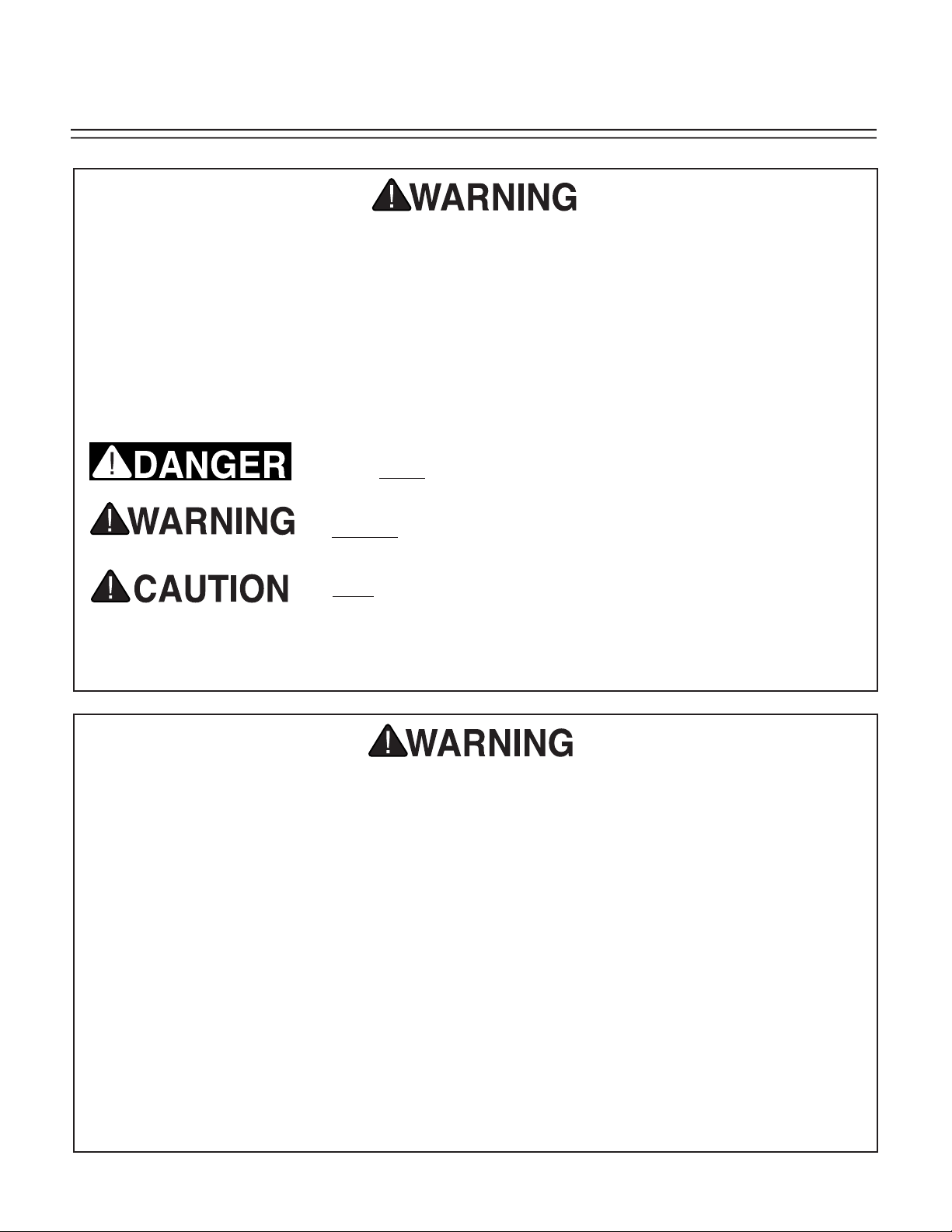
The purpose of safety symbols is to attract your attention to possible hazardous conditions. This
manual uses a series of symbols and signal words which are intended to convey the level of
importance of the safety messages. The progression of symbols is described below. Remember
that safety messages by themselves do not eliminate danger and are not a substitute for proper
accident prevention measures.
Indicates an imminently hazardous situation which, if not
avoided, WILL result in death or serious injury.
Indicates a potentially hazardous situation which, if not avoided, COULD result in death or serious injury.
Indicates a potentially hazardous situation which, if not avoided, MAY result in minor or moderate injury. It may also be
used to alert against unsafe practices.
This symbol is used to alert the user to useful information
NOTICE
about proper operation of the equipment.
Safety Instructions For Power Tools
1. KEEP GUARDS IN PLACE and in working
order.
2. REMOVE ADJUSTING KEYS AND
WRENCHES. Form habit of checking to
see that keys and adjusting wrenches are
removed from tool before turning on
3. KEEP WORK AREA CLEAN. Cluttered
areas and benches invite accidents.
4. DON’T USE IN DANGEROUS
ENVIRONMENT. Don’t use power tools in
damp or wet locations, or where any flam
mable or noxious fumes may exist. Keep
work area well lighted.
.
5. KEEP CHILDREN AND VISITORS AWAY.
All children and visitors should be kept a
safe distance from work area.
6. MAKE WORK SHOP CHILD PROOF with
padlocks, master switches, or by removing
starter keys.
7. DON’T FORCE TOOL. It will do the job
better and safer at the rate for which it was
designed.
8. USE RIGHT TOOL. Don’t force tool or
-
attachment to do a job for which it was not
designed.
-2- G1011 7" x 12'' Bandsaw
Page 4
Safety Instructions For Power Tools
9. USE PROPER EXTENSION CORD. Make
sure your extension cord is in good condi
tion. Conductor size should be in accor
dance with the chart below. The amperage
rating should be listed on the motor or tool
nameplate. An undersized cord will cause
a drop in line voltage resulting in loss of
power and overheating. Your extension
cord must also contain a ground wire and
plug pin. Always repair or replace exten
sion cords if they become damaged.
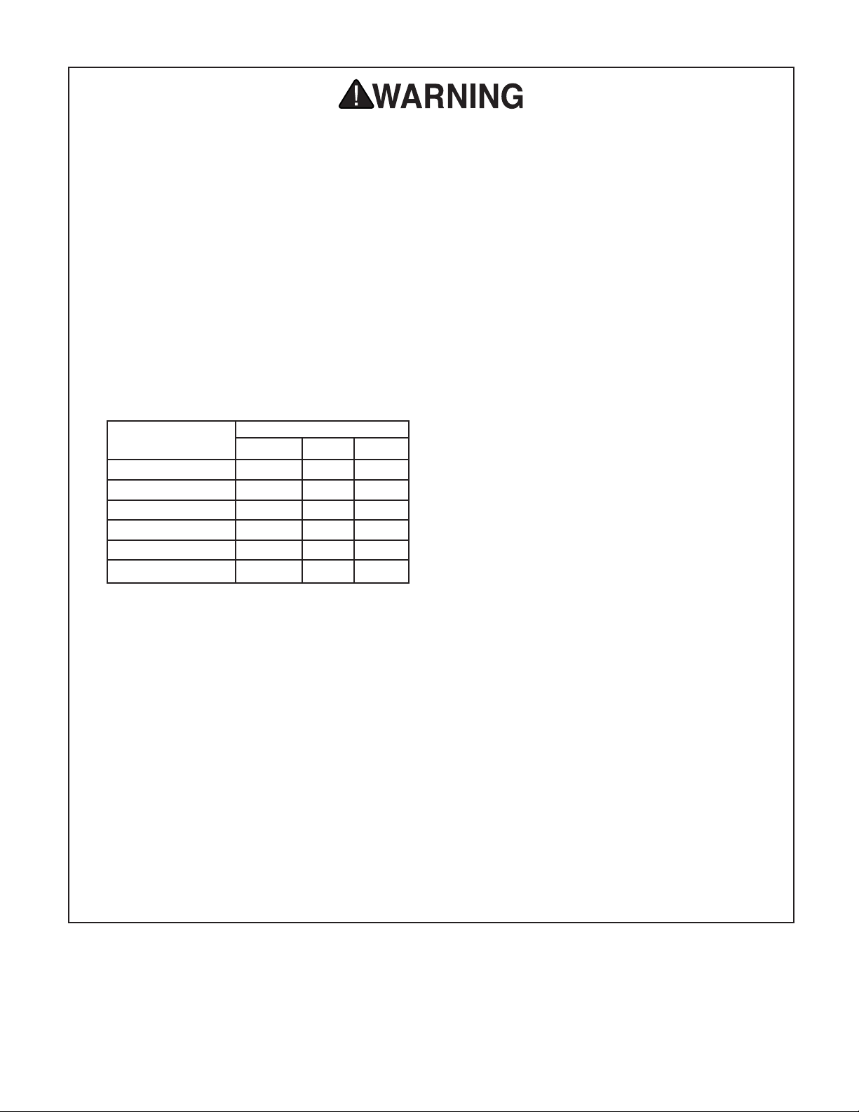
Minimum Gauge for Extension Cords
LENGTH
AMP RATING 25ft 50ft 100ft
0-6 18 16 16
7-10 18 16 14
11-12 16 16 14
13-16 14 12 12
17-20 12 12 10
21-30 10 10 No
10. WEAR PROPER APPAREL. Do not wear
loose clothing, gloves, neckties, rings,
bracelets, or other jewelry which may get
caught in moving parts. Non-slip footwear
is recommended. Wear protective hair cov
ering to contain long hair.
11. ALWAYS USE SAFETY GLASSES. Also
use face or dust mask if cutting operation
is dusty. Everyday eyeglasses only have
impact resistant lenses, they are NOT
safety glasses.
12. SECURE WORK. Use clamps or a vise to
hold work when practical. It’s safer than
using your hand and frees both hands to
operate tool.
13. DON’T OVERREACH. Keep proper foot-
-
-
-
-
ing and balance at all times.
14. MAINTAIN TOOLS WITH CARE. Keep
tools sharp and clean for best and safest
performance. Follow instructions for lubricating and changing accessories.
15. DISCONNECT TOOLS before servicing
and changing accessories, such as blades,
bits, cutters, and the like.
16. REDUCE THE RISK OF UNINTENTIONAL
STARTING. Make sure switch is in off
position before plugging in.
17. USE RECOMMENDED ACCESSORIES.
Consult the owner’s manual for recom
mended accessories. The use of improper
accessories may cause risk of injury.
18. CHECK DAMAGED PARTS. Before fur
ther use of the tool, a guard or other
part that is damaged should be carefully
checked to determine that it will operate
properly and perform its intended func
tion. Check for alignment of moving parts,
binding of moving parts, breakage of parts,
mounting, and any other conditions that
may affect its operation. A guard or other
part that is damaged should be properly
repaired or replaced.
19. NEVER LEAVE TOOL RUNNING
UNATTENDED. TURN POWER OFF.
Don’t leave tool until it comes to a com
plete stop.
-
-
-
-
G1011 7" x 12'' Bandsaw -3-
Page 5
Additional Safety Instructions For The
Metal-Cutting Bandsaw
1. Do not operate your bandsaw with dull
or badly worn blades. Dull blades require
more effort to use and are difficult to con
trol. Inspect blades before each use.
2. Make sure the blade has been properly
tensioned and is tracking on the center of
the wheels
3. Always support stock in the vise and make
certain it is firmly secured. Never attempt
to hold material by hand while sawing.
4. Keep belt guard and bandsaw wheel cov-
ers in place when operating the machine.
5. Never force the saw through the cut. Allow
the feed cylinder to control the rate of cut
ting. If the saw blade binds or stalls turn
the power of immediately.
6. Never position fingers or thumbs in line
with the cut. Serious injury could occur.
-
7. Periodically check the horizontal stop
screw and the automatic shutoff limit
switch to make sure they are properly
adjusted.
8. Exercise great caution when replacing
blades. Wear protective gloves and safety
glasses when handling the blade
9. Support long or heavy workpieces which
extend from the machine bed with a roller
stand or other support device.
10. Habits – good and bad – are hard to
-
break. Develop good habits in your shop
and safety will become second-nature to
you.
Operating this equipment has the poten
tial to propel debris into the air which can
cause eye injury. Always wear safety glass
es or goggles when operating equipment.
Everyday glasses or reading glasses only
have impact resistant lenses, they are not
safety glasses. Be certain the safety glasses
you wear meet the appropriate standards of
the American National Standards Institute
(ANSI).
-4- G1011 7" x 12'' Bandsaw
-
-
Like all power tools, there is danger associated with the Model G1011 Bandsaw.
Accidents are frequently caused by lack
of familiarity or failure to pay attention.
Use this tool with respect and caution to
lessen the possibility of operator injury. If
normal safety precautions are overlooked
or ignored, serious personal injury may
occur.
No list of safety guidelines can be com
plete. Every shop environment is different.
Always consider safety first, as it applies
to your individual working conditions. Use
this and other machinery with caution and
respect. Failure to do so could result in serious personal injury, damage to equipment
or poor work results.
-
Page 6
SECTION 2: CIRCUIT REQUIREMENTS
110V Operation
The Model G1011Z is wired for 110V, single phase
operation only. The 1 HP motor will safely draw
16 amps at 110V. A complete Wiring Diagram for
the motor and switches is provided near the back
of this manual for more information.
Fusing
A 20-amp slow-blow fuse or circuit breaker
should be used on the 110V circuit this bandsaw
is connected to. Circuits rated any higher are
not adequate to protect the motor from power
surges. If you operate this bandsaw on any circuit
that is already close to its capacity, it might blow
a fuse or trip a circuit breaker. However, if an
unusual load does not exist and a power failure
still occurs, contact a qualified electrician or our
service department.
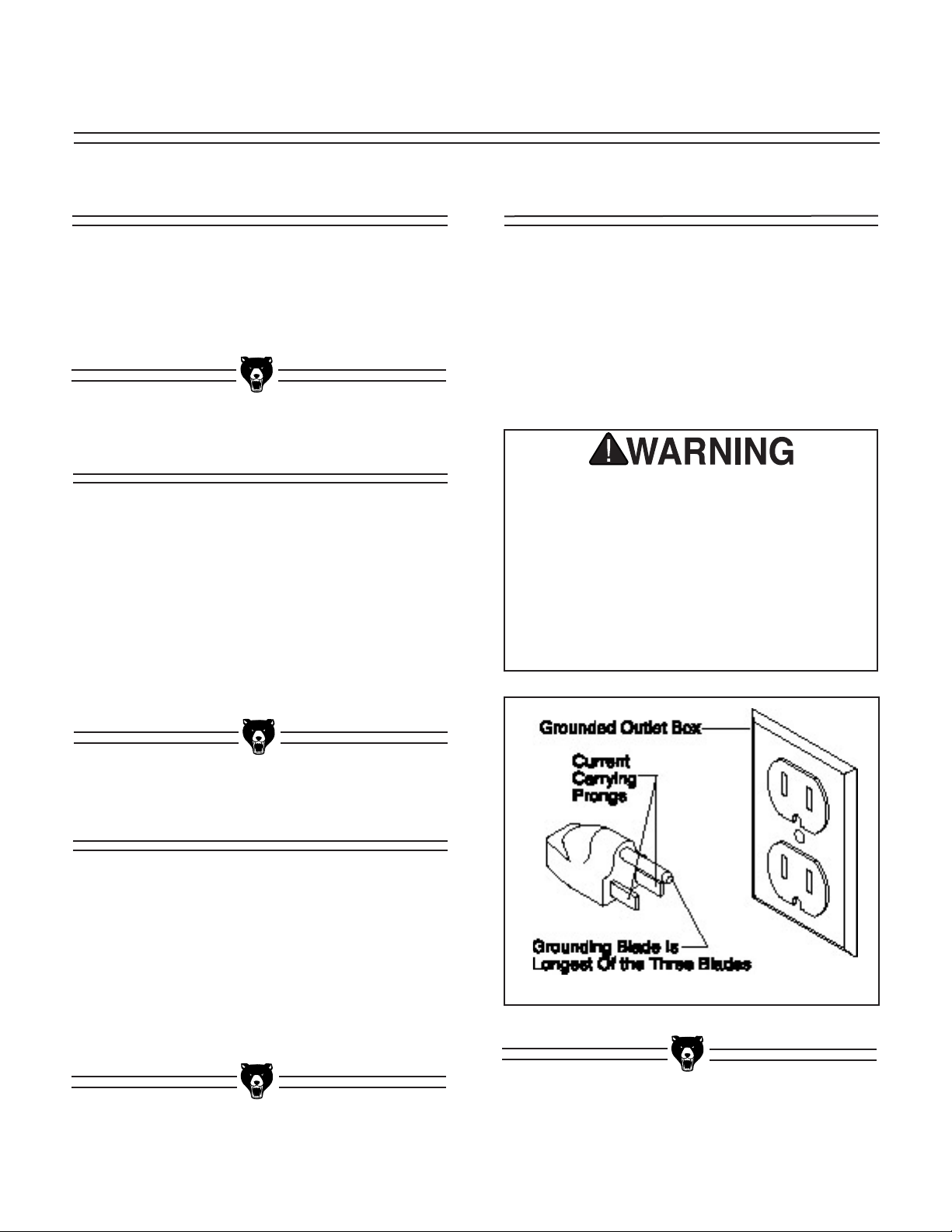
Grounding
In the event of an electrical short, grounding
reduces the risk of electric shock by providing
a path of least resistance to disperse electric
current. This tool is equipped with a power cord
having an equipment-grounding conductor. See
Figure 1. The outlet must be properly installed
and grounded in accordance with all local codes
and ordinances.
This equipment must be grounded. Verify
that any existing electrical outlet and circuit
you intend to plug into is actually ground
ed. If it is not, it will be necessary to run a
separate 12 A.W.G. copper grounding wire
from the outlet to a known ground. Under
no circumstances should the grounding pin
from any three-pronged plug be removed.
Serious injury may occur.
-
Extension Cords
If you find it necessary to use an extension cord
with the Model G1011Z, make sure the cord is
rated Hard Service (grade S) or better. Refer
to the chart in the standard safety instructions
to determine the minimum gauge for the exten
sion cord. The extension cord must also contain
a ground wire and plug pin. Always repair or
replace extension cords when they become worn
or damaged.
G1011 7" x 12'' Bandsaw -5-
-
Figure 1. Grounded plug configuration.
Page 7
SECTION 3: GENERAL INFORMATION
Commentary
Grizzly Industrial, Inc. is proud to offer the Model
G1011Z 7" x 12'' Metal-Cutting Bandsaw. This
saw is a part of Grizzly’s growing family of fine
metalworking machinery. When used according
to the guidelines set forth in this manual, you can
expect years of trouble-free, enjoyable operation,
and proof of Grizzly’s commitment to customer
satisfaction.
The G1011Z features a fully adjustable down
feed, recirculating coolant pump, quick-release
vise, centralized control panel and a 1 HP motor.
The saw comes prewired and ready to operate
at 110V.
We are also pleased to provide this manual with
the G1011Z. It was written to guide you through
assembly, review safety considerations, and
cover general operating procedures. It represents
our latest effort to produce the best documenta
tion possible. If you have any criticisms that you
feel we should pay attention to in our next print
ing, please write to us at the address below:
The specifications, drawings, and photographs
illustrated in this manual represent the Model
G1011Z as supplied when the manual was
prepared. However, owing to Grizzly’s policy
of continuous improvement, changes may be
made at any time with no obligation on the part
of Grizzly. Whenever possible, though, we send
manual updates to all owners of a particular tool
or machine. Should you receive one, we urge
you to insert the new information with the old and
keep it for reference.
-
To operate this or any power tool safely and
efficiently, it is essential to become as famil
iar with it as possible. The time you invest
before you begin to use your Model G1011Z
will be time well spent. DO NOT operate this
machine until you are completely familiar
with the contents of this manual. Serious
personal injury may occur.
-
-
-
Grizzly Industrial, Inc.
C/O Technical Documentation
P.O. Box 2069
Bellingham, WA 98227-2069
Most importantly, we stand behind our machines.
If you have any service questions or parts
requests, please call or write us at the location
listed below.
Grizzly Industrial, Inc.
2406 Reach Road
Williamsport, PA 17701
Phone: (570) 326-3806
Fax: (800) 438-5901
E-Mail: techsupport@grizzlyindustrial.com
Web Site: http://www.grizzlyindustrial.com
-6- G1011 7" x 12'' Bandsaw
Page 8
Unpacking
Clean Up
The bandsaw is shipped from the factory in a
carefully packed crate. If you find the machine
to be damaged after you’ve signed for delivery
and the truck and driver are already gone, you
will need to file a freight claim with the carrier.
Save the containers and all packing materials for
inspection by the carrier or their agent. Without
the packing materials, filing a freight claim can be
difficult. If you need advice regarding this situa
tion, please call us.
The G1011Z is a very heavy machine (626
lbs. shipping weight). DO NOT over-exert
yourself while unpacking or moving your
machine – get assistance. In the event that
your machine must be moved up or down
a flight of stairs, be sure that the stairs are
capable of supporting the combined weight
of people and the machine. Serious per
sonal injury may occur.
-
The unpainted surfaces are coated with a waxy
oil to protect them from corrosion during ship
ment. Remove this protective coating with a
solvent cleaner or citrus-based degreaser. Avoid
chlorine-based solvents as they may damage
painted surfaces should they come in contact.
Always follow the usage instructions on the prod
uct you choose for clean up.
-
Many of the solvents commonly used to
clean machinery can be highly flamma
ble, and toxic when inhaled or ingested.
Always work in well-ventilated areas far
from potential ignition sources when deal
ing with solvents. Use care when dispos
ing of waste rags and towels to be sure
they do not create fire or environmental
hazards. Keep children and animals safely
away when cleaning and assembling this
machine.
-
-
-
-
-
NOTICE
Please keep all packaging materials until
you are satisfied that the machine is in
good condition. Should you need to file a
freight claim, the carrier’s agent will require
inspection of those materials. Settling a
claim can be difficult if packaging is not
available.
When you are completely satisfied with the condition of your shipment, you should inventory its
parts.
Do not use gasoline or other petroleumbased solvents to remove this protective
coating. These products generally have low
flash points which makes them extremely
flammable. A risk of explosion and burning
exists if these products are used. Serious
personal injury may occur.
All die-cut metal parts have a sharp edge
(called “flashing”) on them after they are
formed. This is generally removed at the
factory. Sometimes a bit of flashing might
escape inspection, and the sharp edge may
cause cuts or lacerations when handled.
Please examine the edges of all die-cut
metal parts and file or sand the edge to
remove the flashing before handling.
G1011 7" x 12'' Bandsaw -7-
Page 9
Site Considerations
FLOOR LOAD
Your G1011Z Bandsaw represents a large weight
load in a small footprint. Most commercial or resi
dential shop floors should be sufficient to carry the
weight of the machine. If you have any question
about the floor structure being able to support the
weight, contact your local city building inspector
or a qualified civil engineer or contractor.
WORKING CLEARANCES
Working clearances can be thought of as the
distances between machines and obstacles that
allow safe operation of every machine with
out limitation. Consider existing and anticipated
machine needs, size of material to be processed
through each machine, and space for auxiliary
stands and/or work tables. Also consider the rela
tive position of each machine to one another for
efficient material handling. Be sure to allow your
self sufficient room to safely run your machines
in any foreseeable operation.
Notes
-
-
-
-
LIGHTING AND OUTLETS
Lighting should be bright enough to eliminate
shadow and prevent eye strain. Electrical circuits
should be dedicated or large enough to handle
combined motor amp loads. Outlets should be
located near each machine so power or exten
sion cords are not obstructing high-traffic areas.
Be sure to observe local electrical codes for
proper installation of new lighting, outlets, or
circuits.
Make your shop “child safe”. Ensure that
your workplace is inaccessible to young
sters by closing and locking all entrances
when you are away. Never allow visitors in
your shop when assembling, adjusting or
operating equipment.
-
-
-8- G1011 7" x 12'' Bandsaw
Page 10
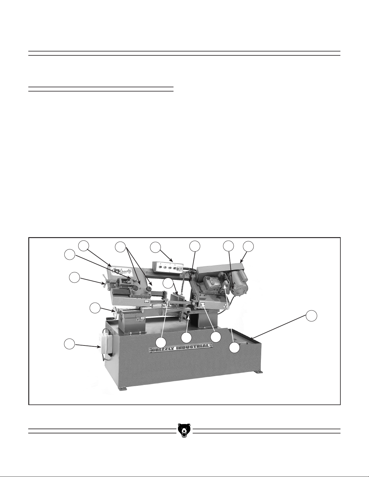
SECTION 4: ADJUSTMENTS
Controls
The controls and major components for the
G1011Z metal-cutting bandsaw are shown below
in Figure 2. Please use this drawing for refer-
ence when reviewing the following sections.
A. Saw Bow.
B. Blade Guide Locking Knobs.
C. Control Panel - Contains On/Off buttons,
Power-On indicator light, Coolant On/Off
switch, and the Feed Rate valve.
D. Flexible Coolant Line.
E. Motor Mount (E1) and Belt Guard (E2).
F. Coolant Tank.
G. Gear Box.
H. Stationary Blade Guide.
I. Material Stop Assembly.
J. Moveable Blade Guide.
K. Vise Movable Jaw (K1) and Vise Lead
Screw (K2).
L. Magnetic Starter Switch Box.
M. Blade Tensioning Adjustment Handle.
N. Blade Tracking Adjustment Setscrew.
A
N
M
K2
B
C
K1
D
E1
E2
F
L
Figure 2. Controls
J
I
and key components.
H
G
G1011 7" x 12'' Bandsaw -9-
Page 11
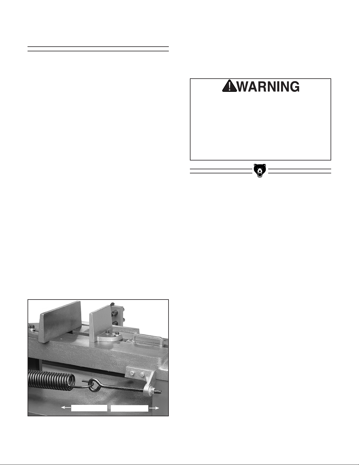
Saw Pressure
The pressure or force which the saw exerts when
pushing through the workpiece is the result of
the weight of the bow assembly counterbalanced
by the amount of spring tension applied through
the large coil spring on the back of the machine
base. This should be set so there is a moderate
amount of pressure. Harder or softer materials
may require adjusting the head pressure for spe
cific operations. See Adjusting Feed Rate in the
Operations Section.
Spring adjustment is performed in the following
sequence:
1. Raise saw bow to the open position, with
the bow at the top of its travel.
2. Open the hydraulic feed rate valve all the
way by turning it counterclockwise.
5. If it is easy to stop the travel, or if the
saw bow wants to reverse direction, then
the spring tension is too strong. Turn the
adjusting nut clockwise so more of the eye
bolt threads extend beyond the bracket.
Use caution when adjusting the saw bow.
-
Keep hands and arms clear of the cutting
area when releasing the cylinder pressure
to lower the saw. Even with the saw off,
the weight of the bow can severely lacer
ate or break a hand or arm which might
get trapped between the saw and the bed.
Serious personal injury may result.
-
3. The saw bow should come down at a slow
steady rate. You should be able to stop its
travel with a light upward force from one or
two fingers.
4. If it is hard to stop the travel, then the spring
tension is too weak. Turn the adjusting nut
on the spring’s eye bolt (See Figure 3)
counterclockwise so there is less of the eye
bolt threads extending beyond the bracket.
Less Pressure
More Pressure
Figure 3. Adjusting spring tension.
-10- G1011 7" x 12'' Bandsaw
Page 12
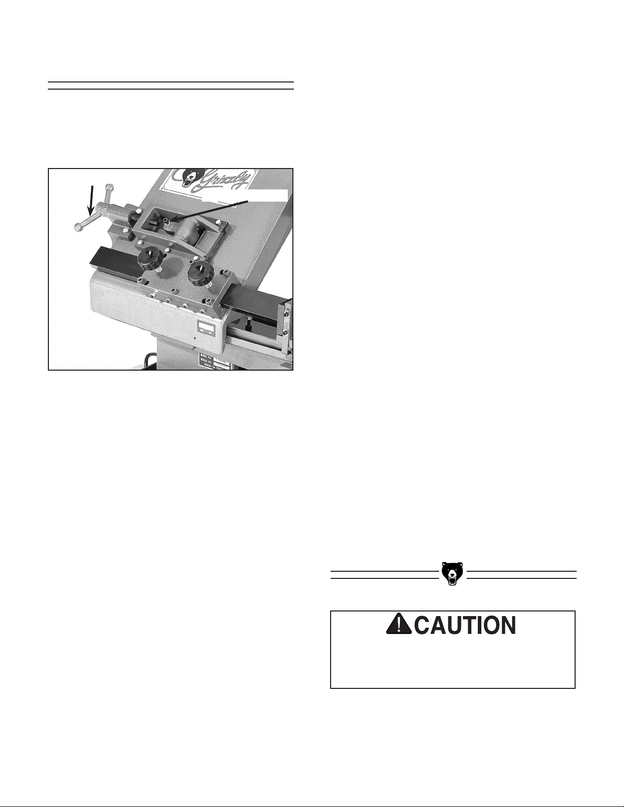
Tension/Tracking
Proper blade tension and tracking are important
for optimum bandsaw performance. See Figure
4 for bandsaw tension and tracking control locations.
Tension Control
Tracking Control
Figure 4. Tension and tracking controls.
TENSION
If the tension seems correct, make the other
adjustments to the saw (aligning guides, tracking
and speed) and test run it on a scrap piece of
material. If the blade is not cutting properly, the
tension may be incorrect and you’ll need to read
just the tension. Remember to reduce the blade
tension when the saw will not be in use, this will
help to prevent premature wear or breakage of
the blade.
TRACKING
To adjust tracking, disconnect the bandsaw from
the power source. Raise the saw bow as high
as possible and remove the cap screw from the
hinged wheel cover. This will allow you to see the
bandsaw wheel which has a machined step and
a groove on it.
The socket head cap screw and lock nut on the
top of the saw bow changes the plane of rotation
of this wheel. Turn the wheel by hand (remove
the belt guard and turn the motor pulley) for a
few revolutions and observe whether the edge of
the blade stays snug against the machined step.
If it does not, adjust the cap screw until the blade
stays against that step through several complete
revolutions of the blade.
-
Since a number of blade metal types and tooth
configurations will work in this saw, proper blade
tension is dependent upon the type of blade and
the material to be cut. Too much tension will
result in blade breakage. A properly tensioned
blade will track the cutting line accurately and the
cut will be smoother.
Initially proper blade tension can best be achieved
by determining the amount of blade deflection:
1. Ensure that the power is off and the saw is
unplugged. Slide the blade guide assembly
all the way to the left so the blade is fully
exposed.
2. Press, with moderate pressure, on the face
of the blade with your thumb.
3. Turn the tensioning knob at the top of the
machine to change the amount of tension.
The blade should flex no more than
1
/4".
Once it stays centered when rotated by hand,
lock the cap screw in place with the locking nut.
Reconnect the machine to power and turn the
machine on for just a few seconds. Observe the
action of the blade and the wheel during this test,
being sure to maintain a safe distance should
the blade become disengaged. If the blade stays
snug to the step, close the cover and secure with
the cap screw.
The saw blade is dangerously sharp. Use
extra care when handling the blade, or work
ing near it. Serious injury is possible.
-
G1011 7" x 12'' Bandsaw -11-
Page 13
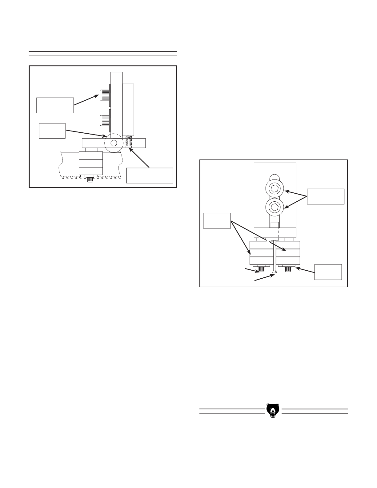
Blade Guides
Securing
Cap Screws
Support
Bearing
Fine Adjustment
Set Screws
2. Guide Bearings - The guide bearings ride
on either side of the blade and ensure that
the blade is not pushed too far laterally. To
adjust the guide bearings, loosen the cap
screw at the bottom of the bearing assem
bly. Use an open end wrench to move the
brass hex nut which is an eccentric bush
ing. Turning the hex nut will move the bear
ing assembly into or away from the blade.
When the bearings are just touching the
blade, tighten the cap screw. Repeat this
procedure for all four guide bearing assem
blies. The bearings should be able to be
rotated by hand while still touching the side
of the blade. See Figure 6
.
-
-
-
-
Figure 5. Support Bearing Adjustments.
Whenever changing a blade or adjusting tension
and tracking, the left and right hand blade support
bearings and guide bearings must be re-adjust
ed. Always adjust the guide bearings away from
the blade before installing a new blade or making
blade tracking adjustments. After blade tension
and tracking are set correctly, re-adjust the left
and right support bearings and guide bearings
into position.
Adjustment of the guides is a three step pro
cedure, consisting of adjustments to both the
support bearings and guide bearings. The adjust
ments are as follows:
1. Support Bearings - The support bearings
guide the back edge of the blade during
the sawing operation. There is one bearing
each on the left and right hand guides.
Figure 5. To adjust the support bearings,
loosen the two cap screws until the blade
guide block can be moved. Move the block
so the bearing just touches the back of the
blade. Tighten the cap screw closest to
the blade, leave the other loose for now.
Use the two fine adjustment set screws to
back the bearing away from the blade until
it is between .003'' and .005'' away from
the edge of the blade. It may help to use a
feeler gauge to check the gap. Be sure to
adjust both the left and right hand sides.
See
Securing
Cap Screws
Guide
-
-
-
Bearings
Eccentric
Bushing
Figure 6. Guide Bearing Adjustments.
3. Blade Square To Table - The blade guide
bearings must also be adjusted to make
sure the blade is perpendicular to the sur
face of the table. Lower the saw bow all the
way down until it contacts the stop screw.
Use a machinist’s square with one edge on
the bed table surface and the other against
the side of the blade. With the upper secur
ing bolt still loose, rotate the guide bearings
assembly block until the blade is square.
Now tighten the upper and lower bolts to
secure this position.
-
-
-12- G1011 7" x 12'' Bandsaw
Page 14

Horizontal Stop Screw
Auto Shut-Off
The horizontal stop screw limits the downward
travel of the saw bow to keep the blade from
running into the cast iron bed. The stop screw is
located on the saw bow just next to the left hand
blade wheel cover. See Figure 7.
Lower the saw bow by opening the feed rate
valve. Stop the bow when the teeth are just
below the top surface of the bed. Adjust the stop
screw so it touches the bed surface. Tighten the
locknut on the stop screw.
1
⁄8''
Locknut
Stop Screw
The motor should shut off immediately after
the blade has cut through the material and just
before the head comes to rest on the horizontal
stop screw. The automatic shut off limit switch is
located near the saw bow pivot point next to the
hydraulic cylinder. See Figure 8.
Turn the saw on (after making sure the blade
tensioning and tracking is correct), and lower
the saw bow slowly. The saw should turn off just
before the saw bow hits the stop screw. If it does
not shut off at the proper point, the limit switch
needs adjustment.
Loosen the two screws holding the limit switch
bracket, and raise or lower the switch until the
proper shut off point is achieved. If the switch is
manually depressed, you will hear a click at the
point the switch is being activated. You can use
this activation point to set the switch in the proper
position without the saw power being on.
After positioning the switch, double check its
operation to make certain it is shutting off the
blade just before contacting the horizontal stop
screw.
Figure 7. Horizontal stop screw.
Figure 8. Automatic shut-off switch.
G1011 7" x 12'' Bandsaw -13-
Page 15

SECTION 5: OPERATIONS
The metal-cutting bandsaw is one of the most
versatile machines in the shop. It can be used
to cut off bar stock and structural steel to length
as well as shaping metal into semifinished and
finished components.
Pre-Run Check
There are many adjustment points and compensating differences to consider when operating
this type of saw. Therefore, cutting results can
be somewhat unpredictable if some or all of the
crucial adjustments are neglected. Here are a few
simple things you can do to increase the predict
ability of your bandsaw’s performance:
1. Blade Type - Is the blade the proper
tooth count and blade configuration for the
material you need to cut? Is it sharp? Is it
installed in the machine so the teeth are
pointing in the right direction, according to
the label on the saw bow.
2. Blade Tensioning - Is the blade tensioned
properly? Is the blade tracking evenly on
the wheels?
3. Blade Guides - Are the blade guides
adjusted so the bearings are just touching
the blade without binding. The movable
blade guide on the left hand side should be
moved as close to the material to be cut as
possible.
4. Speeds and Feeds - Has the proper cut
ting speed been selected for the type of
material to be cut? Has the proper feed rate
for the bow been set for the type of material
to be cut?
6. Coolant - Has the coolant reservoir been
filled with the proper type of coolant solution
to the manufacturer’s mix ratio? Is the cool
ant nozzle directed at the cutting location
and is the pump on?
7. Operator Safety - Is the machine operator
wearing safety goggles and hearing protec
tion? Avoid standing directly in front of the
machine while it is cutting, stand to one side
yet close enough to reach the control panel
if needed.
-
The Model G1011Z Bandsaw is a powerful,
professional-quality machine, designed and
built to provide outstanding results when
used cautiously and with respect. Like any
machine of its type, the Model G1011Z has
some inherent dangers, which, when used
with a lack of care, can result in serious
injury or fatality. Please do not attempt
to use this machine without familiarizing
yourself with the instructions for assembly,
adjustment, and safe operation. Failure to
do so could result in serious personal injury, as well as property damage and damage
-
to the machine.
-
-
5. Vise - Is the material to be cut securely held
in the vise? Is the vise oriented to the blade
properly? Is the material situated in such a
manner that the cutting will not begin on a
sharp corner?
-14- G1011 7" x 12'' Bandsaw
Page 16

Blade Selection
A bandsaw blade is a ribbon of steel subjected
to tremendous strain. Be sure you use qual
ity blades for the various types of cutting opera
tions. The Grizzly G1011Z bandsaw accepts 1'' x
101" blades. Bandsaw blades can be purchased
welded, set, and sharpened ready-for-use from
most saw shops. We also supply tool steel and
variable pitch bi-metal blades for this saw. Please
refer to our current catalog for prices and ordering
information.
There are several key factors to consider in
choosing a blade:
Tooth Pitch - The number of teeth per inch
(TPI) on the blade, also known as tooth
pitch. Select a pitch which will assure that
at least three teeth are contacting the
workpiece while cutting. This helps to dis
tribute the cutting forces and avoids tooth
breakage.
Many conditions can lead to breakage. Blade
breakage is, in some cases, unavoidable, since it
is the natural result of the peculiar stresses that
bandsaw blades are subjected to. Blade break
age is also due to avoidable causes. Avoidable
-
-
-
breakage is most often the result of poor care
or judgement on the part of the operator when
mounting or adjusting the blade or support guides.
The most common causes of blade breakage are:
(1) faulty alignment and adjustment of the guides;
(2) Insufficient number of teeth contacting the cut;
(3) feeding too fast; (4) tooth dullness or absence
of sufficient set; (5) excessive tension; (6) using
a blade with a lumpy or improperly finished weld;
and (7), continuously running the bandsaw when
not in use.
Gullet
-
Tooth Form - There are four common forms
of teeth on the blade: buttress, claw-tooth,
precision and tungsten carbide. Precision is
the most common and is the type supplied
with this saw. See Figure 9. It is the most
versatile and it provides a good surface
finish.
Tooth Set - Set is the degree to which the
teeth are bent away from the blade. Typical
tooth set styles are raker, wave and straight
set. Raker set is the most common with one
tooth offset to the right, the next one to the
left, and the third is straight. A wave set
will have 3-4 teeth bent progressively one
direction, then to the other in a wave-like
pattern. A straight set is alternating teeth
set right, then left.
Always select and use good-quality saw blades
and choose the right blade for the job. Discuss
your cutting requirements with your saw blade
dealer to make sure you are getting the type of
blade which best suits your need. Poor quality
blades and improper use are often the cause of
premature blade failure.
Gullet Line
Figure 9. A precision tooth, raker set blade.
Operating this equipment has the potential to propel debris into the air which can
cause eye injury. Always wear safety glass
es or goggles when operating equipment.
Everyday glasses or reading glasses only
have impact resistant lenses, they are not
safety glasses. Be certain the safety glasses
you wear meet the appropriate standards of
the American National Standards Institute
(ANSI).
-
G1011 7" x 12'' Bandsaw -15-
Page 17

Changing Blades
Use extreme caution when replacing blades.
Teeth are dangerously sharp and coiled
blades are prone to spring when released
from their packaging. Use heavy leather
or welding gloves and safety glasses or
goggles whenever handling blades. Failure
to do so could result in serious personal
injury.
To remove the blade, ensure the power is discon
nected and raise the saw bow as high as it will
go:
1. Loosen tension on the blade by turning the
tension knob.
2. Open the gap between the blade bearing
guides by loosening the locking screw and
turning the eccentric bushing with an open
end wrench. See Blade Guide Adjustment
section.
3. Remove the cap screws from the cover
plates over both of the bandsaw wheels.
At the outer end of the bow the cover is
hinged, at the other the plate must be com
pletely removed.
4. Slide the blade off both wheels and out of
the blade guides. Use caution, the blades
are sharp!
See Figure 10.
-
-
Figure 10. Outer wheel and cover.
3. Apply tension to the blade by turning the
tension control knob. Refer to blade ten
sioning instructions earlier in this section.
4. Adjust the guide blocks and bearings as
described in the previous section.
5. Close the wheel covers. Install the cap
screws to secure the covers.
-
To replace the blade, ensure that the power is
disconnected and:
1. Position the blade so the teeth are pointing
down and toward the right when you are
facing the front of the machine. There are
blade tooth direction labels on the front of
the saw. If the teeth will not point downward
in any orientation, the blade is inside out.
Twist it until it is right side out.
2. Slip the blade through the left and right hand
guides and mount over the two wheels.
-16- G1011 7" x 12'' Bandsaw
Page 18

Cutting Speed
Blade speed selection should be made according
to the material being cut. In general, the harder
the material the slower the blade speed. The
chart in Figure 12 provides a general reference.
Motor Pulleys
Saw Pulleys
Material
Hard Materials High Speed steels,
stainless and heavy
cross section mat’l
Moderately Hard
- Tool, stainless and
alloy steels, bearing
bronzes
Moderately Soft
- Cast iron, mild
steel, hard brass
and bronze
Soft Materials Plastic, copper, soft
brass, aluminum,
other light materials
Figure 11. Cutting speeds and pulley selection.
The speed is changed by moving the V-belt onto
the different sized pulleys on the motor and the
saw. See Figure 12.
Speed
FPM
63
104
156
206
Pulley Used
Motor
smallest
small
medium
large
Saw
large
medium
small
smallest
Tension Knob
Figure 12. Motor and saw blade pulleys.
DO NOT attempt to assemble, adjust, or
maintain this machine while it is running.
Turn off the switch, disconnect the bandsaw
from its power source and wait for all
moving parts to come to a complete stop
before attempting any adjustments or maintenance. Failure to do so could result in
serious injury.
1. Remove the belt guard.
2. Loosen the motor tension knob.
3. Pull the motor over to relieve the belt
tension. Move the belt to one of the four
desired locations according to the speed
chart. Never cross the belt so it is diagonal
across the pulleys.
4. Tighten the motor tension knob.
5. Replace the belt guard.
G1011 7" x 12'' Bandsaw -17-
Page 19

Adjusting Feed Rate
Coolant
The hydraulic cylinder connected to the saw bow
regulates the rate at which the blade is lowered
into the workpiece. Opening and closing the valve
on the control panel (See Figure 13) controls the
feed rate.
There is a by-pass valve on the side of the
hydraulic cylinder which is preset at the factory.
This by-pass allows the pressure to be relieved
if for some reason the saw bow is forced down
ward. Do not attempt to adjust the by-pass valve
setting.
Regulator Valve
Use of the coolant system is optional and is
dependent upon the type of material being cut
and the quantity. Directing coolant on the cut
keeps the blade and workpiece from overheating,
and it flushes the metal chips away from the tooth
area to keep a good cutting surface.
The coolant tank is at the bottom of the machine
on the right hand side. See Figure 14.
-
the coolant solution to this tank, and locate the
submersible pump so the suction intake is com
pletely submerged. Generally water soluble fluids
will work best. Refer to the specific mixing and
replacement instructions of the coolant manufac
turer. A drain plug is located at the corner of the
tank to allow the easy draining of the coolant.
Turn the coolant pump on at the control panel,
and direct the coolant nozzle directly at the cut.
Add
-
-
Figure 13. Feed regulator on control panel.
Figure 14. Coolant pump.
-18- G1011 7" x 12'' Bandsaw
Page 20

Guide Adjustment
Vise and Stop
The blade will cut best when the blade is supported as close to the workpiece as possible. Once
the material has been secured in the vise, loosen
the two knobs on top of the saw bow and slide the
moveable guide over as close to the material as
possible without interfering with the cut. Tighten
the knobs. See Figure 15.
Figure 15. Moveable blade guide.
The workpiece(s) must always be secured in the
vise for cutting. Never attempt to hold the mate
rial by hand, the cutting forces on a metal-cutting
bandsaw are too strong. The angle of the cut can
be revised by loosening the cap screws securing
the vise jaws to the table and turning them to the
angle desired. Tighten the cap screws.
One side of the vise slides along the bed when
the handle lifts the threads off the lead screw.
See Figure 16. Place the material to be cut
between the sides of the vise jaws, and move the
sliding portion as close to the material as pos
sible. Seat the handle on the lead screw threads.
Then using the handwheel on the left hand side
of the bed, tighten the jaws until the material is
firmly secured. Never release the vise by pulling
up on the handle. Damage to the screw and nut
will occur and may render it unusable.
Just in front of the vise, protruding from beneath
the table, is the material stop bar. This can be set
so that material can be cut to the same length
over a series of cuts. Set the length of cut by
measuring from the plane of the saw blade to the
end of the stop bar. Tighten the thumb screws.
Slide the material so it contacts the stop bar.
Activate the saw and make the cut. Raise the saw
bow and advance the material so it once again
touches the stop bar. This will assure the cuts are
made to the same exact length.
-
-
Fixed Jaw
Movable
Jaw
Release
Handle
Figure 16. Vise components.
G1011 7" x 12'' Bandsaw -19-
Material Stop
Page 21

SECTION 6: MAINTENANCE
Table
The table and other non-painted surfaces on the
Model G1011Z should be protected against rust
and pitting. Wiping the saw clean after every use
helps to ensure that coolant and chips won’t begin
to corrode the working surfaces of the bandsaw.
Protect the table surfaces with a light coating of
oil periodically, especially when the saw will not
be used for a time period.
V-Belt
To ensure optimum power transmission from the
motor to the blade, the V-belt must be in good
condition and must be under the proper tension.
The belt should be checked for cracks, fraying
and wear. Belt integrity should be checked at
least every 3 months; more often if the bandsaw
is used daily.
Make sure the belt is tensioned properly whenev
er speed changes are made Refer to the Cutting
Speed section for more complete detail on the
speeds and moving the belt.
-
Make your workshop “child-safe.” Remove
all safety keys from this and other machin
ery when they’re not in use. Place sharp
tools and blades high enough to discourage
curious fingers. Store lubricants, finishes
and other harmful chemicals where they
can’t be easily reached. Lock your workshop securely when you are away.
Operating this equipment has the potential to propel debris into the air which can
cause eye injury. Always wear safety glass
es or goggles when operating equipment.
Everyday glasses or reading glasses only
have impact resistant lenses, they are not
safety glasses. Be certain the safety glasses
you wear meet the appropriate standards of
the American National Standards Institute
(ANSI).
-
-
-20- G1011 7" x 12'' Bandsaw
Page 22

Lubrication
Miscellaneous
The bearings used in the motor, the wheels and
the blade guides are shielded and pre-lubricated
ball bearings. These require no lubrication for
the life of the bearings. All bearings are standard
sizes and replacements can be purchased from
our parts department or bearing supply store.
The rod on which the saw bow pivots needs
an occasional shot of light oil to keep it moving
smoothly.
The gear box should not need changing unless
the oil becomes contaminated or leaks. To check
the oil, lower the saw bow down all the way and
wait a few minutes for the oil to drain down. Open
the oil cap on top of the gearbox. The gear case
is full when the oil is up to the bottom of the filler
hole. Use 90W gear oil if it becomes necessary to
change or add to the oil.
Always be aware of the condition of your bandsaw
before using it. Routinely check the condition of
the following items and repair or replace as nec
essary.
1. Worn or damaged blade.
2. Worn switches.
3. Loose mounting bolts.
4. Worn or damaged support bearings or
guide bearings.
-
Coolant System
The coolant system must be properly filled with
the proper mix of coolant and water in accor
dance with the coolant manufacturer’s specifi
cations. The coolant will need to be replaced
periodically as the bandsaw is used more. Some
coolant types also breakdown over time, or need
additives to reduce the growth of bacteria or fun
gus in the solution.
There is a filter in the bottom of the coolant pump
which will need periodic cleaning or replacement.
Any time coolant flow does not seem sufficient,
check the coolant sump for level, and check the
pump filter.
-
-
-
G1011 7" x 12'' Bandsaw -21-
Page 23

SECTION 7: CLOSURE
The following pages contain general machine
data, parts diagrams/lists, troubleshooting guide
and Warranty/Return information for your Model
G1011Z Metal-Cutting Bandsaw.
If you need parts or help in assembling your
machine, or if you need operational information, we encourage you to call our Service
Department. Our trained service technicians will
be glad to help you.
If you have comments dealing specifically with
this manual, please write to our Bellingham,
Washington location using the address in Section
3 General Information The specifications, draw
ings, and photographs illustrated in this man
ual represent the Model G1011Z as supplied
when the manual was prepared. However, due
to Grizzly’s policy of continuous improvement,
changes may be made at any time with no obli
gation on the part of Grizzly. Whenever possible,
though, we send manual updates to all owners of
a particular tool or machine. Should you receive
one, add the new information to this manual and
keep it for reference.
We have included some important safety mea
sures that are essential to this machine’s opera
tion. While most safety measures are generally
universal, Grizzly reminds you that each work
shop is different and safety rules should be con
sidered as they apply to your specific situation.
Operating this equipment has the potential
for flying debris to cause eye injury. Always
wear safety glasses or goggles when operat
ing equipment. Everyday glasses or reading
glasses only have impact resistant lenses,
they are not safety glasses. Be certain the
safety glasses you wear meet the appro
priate standards of the American National
Standards Institute (ANSI).
-
-
We recommend you keep a copy of our current catalog for complete information regard
ing Grizzly's warranty and return policy. If you
need additional technical information relating
to this machine, or if you need general assis
tance or replacement parts, please contact the
Service Department listed in Section 3: General
Information.
Additional information sources are necessary to
realize the full potential of this machine. Trade
journals, woodworking magazines, and your local
library are good places to start.
-
-
The Model G1011Z was specifically designed
for metal-cutting operations. DO NOT MODIFY
-
-
-
-
-
AND/OR USE THIS MACHINE FOR ANY
OTHER PURPOSE.
er use of this tool will void the warranty. If you
are confused about any aspect of this machine,
DO NOT use it until you have answered all
your questions. Serious personal injury may
occur.
Like all power tools, there is danger associated with the Model G1011Z Metal-Cutting
Bandsaw. Accidents are frequently caused
by lack of familiarity or failure to pay atten
tion. Use this tool with respect and caution
to lessen the possibility of operator injury.
If normal safety precautions are overlooked
or ignored, serious personal injury may
occur.
Modifications or improp-
-
-
-
-22- G1011 7" x 12'' Bandsaw
Page 24

MACHINE DATA
SHEET
Customer Service #: (570) 326-3806 • To Order Call: (800) 523-4777 • Fax #: (800) 438-5901
GRIZZLY MODEL G1011 METAL-CUTTING BANDSAW
Design Type ......................................................................................................Floor Model
Overall Dimensions:
Crate Size ............................................................................ 68" L x 27
Foot Print .........................................................................................................57" x 23"
Angle Cuts .......................................................................................................45° - 90°
Length ...................................................................................................................631⁄4"
Width (front to back) .................................................................................................
Height (head in high position) ...............................................................................
Height (from floor to cutting area) .........................................................................
Weight (shipping) ............................................................................................. 626 lbs.
Weight (Net) ..................................................................................................... 548 lbs.
Capacities:
Maximum Cutting Capacity ..................................................................7" Round Stock
Maximum Cutting Capacity ....................................................... 7" x 11
Bed Size .......................................................................................................
Cuts .................................................................................................................45° - 90°
Blade Size .......................................................................................................1" x 101"
Blade Speeds ........................................................................... 63, 106, 156, 206 FPM
Construction:
Main Body ....................................................................................................... Cast Iron
Stand ............................................................................................ Formed and Welded
Wheels ............................................................................................................ Cast Iron
Gear Box ...................................................................Sealed & Lubricated Worm Gear
Blade Guides ................................................................................ 7 Ball Bearing Guide
Motor:
Type .............................................................................. Capacitor Start Induction Run
Horsepower ........................................................................................................... 1 HP
Phase ⁄ Cycle .............................................................................. Single Phase ⁄ 60 HZ
Voltage ..............................................................................(prewired 110V) 110V⁄220V
Amps .................................................................................................................... 16 ⁄ 8
RPM .............................................................................................................1725 RPM
Bearings ...........................................................Shielded and Lubricated-For-Life ⁄ Ball
Switch ..............................................................................................Automatic Shut Off
Features:
............................................................ Centralized Control Panel on Top of Saw Bow
........................................................................... Heavy-Duty, all steel one-piece base
.......................... Adjustable hydraulic down-feed—dial feed rate on the control panel
............................................................ Worm-gear box has hardened & ground gears
........................................................................Quick release vise for fast job changes
............................ Built in coolant system (tank not removable) uses water soluble oil
1
⁄2" W x 471⁄4" H
27"
661⁄2"
251⁄2"
5
⁄8" Rectangular
81⁄4 x 171⁄2" A n g l e
Specifications, while deemed accurate, are not guaranteed.
REVISED 5/99
G1011 7" x 12'' Bandsaw -23-
Page 25

TROUBLESHOOTING
SYMPTOM
Teeth Breakage
Blade breakage.
Cut not straight.
Blade Twisting.
POSSIBLE CAUSE
1. Too few teeth per inch.
2. Excessive loading of gullets.
3. Excessive feed rate.
4. Work not secured in vise.
1. Teeth too coarse.
2. Misalignment of guides.
3. Dry cutting
4. Excessive speed.
5. Excessive feed
6. Excessive tension.
1. Wheels out of line.
2. Guides out of line.
3. Excessive feed pressure.
4. Insufficient blade tension
5. Work not secured in vise.
1. Blade not aligned with blade
guides.
2. Excessive feed pressure.
3. Excessive feed rate.
CORRECTIVE ACTION
1. Use finer tooth blade (make sure at least three teeth
contact the workpiece).
2. Use coolant or increase coolant flow, or use coarser
tooth blade.
3. Decrease feed rate.
4. Check that vise is tight to the bed and the movable
jaw is tightened.
1. Use a finer tooth blade.
2. Adjust blade support and guide bearings.
3. Use coolant system.
4. Decrease cutting speed
5. Decrease cutting feed rate.
6. Reduce blade tension
1. Adjust blade tracking.
2. Adjust support and guide bearings.
3. Adjust spring tension to reduce feed pressure.
4. Increase blade tension.
5. Check that vise is tight to the bed and the movable
jaw is tight on the material to be cut.
1. Adjust support and guide bearings, check alignment
of blade to table.
2 Adjust spring tension to reduce feed pressure.
3. Reduce feed rate at control panel.
-
Premature tooth wear.
Repetitive ticking noise
when blade is on.
Blade does not run even
ly on wheels or runs off.
Blade does not cut
evenly.
Blade contacting table
surface.
Blade does not stop after
cut is complete.
1. Dry cutting.
2. Blade too coarse.
3. Insufficient feed rate.
4. Excessive speed.
5. Tooth set is uneven.
1. Blade weld contacting support
or guide bearings.
2. Blade weld may be failing.
-
1. Tracking is not adjusted prop
erly.
1. Blade tension is incorrect.
2. Tooth set is uneven.
3. Teeth are sharper on one side
than the other.
1. Horizontal stop screw not
adjusted.
1. Automatic shut-off switch not
adjusted.
1. Use coolant system.
2. Use finer tooth blade.
3. Increase feed rate so that blade does not ride in cut.
4. Reduce cutting speed.
5. Replace blade, or have it professionally sharpened.
1. Use file or stone to smooth and round the back of the
blade.
2. Inspect and replace blade if necessary.
1. Adjust tracking.
-
1. Adjust tension.
2. Replace blade, or have it professionally sharpened.
3. Replace blade, or have it professionally sharpened.
1. Adjust horizontal stop screw.
1. Adjust automatic shut-off switch.
-24- G1011 7" x 12'' Bandsaw
Page 26

TROUBLESHOOTING
SYMPTOM
Motor will not start.
Motor will not start; fuses
or circuit breakers blow.
Motor overheats.
Motor stalls (resulting in
blown fuses or tripped
circuit).
Motor and blade speed
slows when operating.
POSSIBLE CAUSE
1. Low voltage.
2. Open circuit in motor, control
panel or magnetic starter.
1. Short circuit in line cord or
plug.
2. Short circuit in motor or loose
connections.
3. Incorrect fuses or circuit break
ers in power line.
1. Motor overloaded.
2. Air circulation through the motor
restricted.
1. Short circuit in motor or loose
connections.
2. Low voltage.
3. Incorrect fuses or circuit break
ers in power line.
4. Motor overloaded.
1. Excessive feed pressure.
2. Blade is dull.
CORRECTIVE ACTION
1. Check power line for proper voltage.
2. Inspect all lead connections on motor, switch and
starter for loose or open connections.
1. Inspect cord or plug for damaged insulation and
shorted wires.
2. Inspect all connections on motor for loose or shorted
terminals or worn insulation.
-
3. Install correct fuses or circuit breakers.
1. Reduce load on motor.
2. Clean out motor to provide normal air circulation.
1. Inspect connections on motor for loose or shorted
terminals or worn insulation.
2 Correct the low voltage conditions.
3. Install correct fuses or circuit breakers.
-
4. Reduce load on motor.
1. Adjust spring tension to reduce feed pressure.-
2. Replace blade.
G1011 7" x 12'' Bandsaw -25-
Page 27

G1011Z 110 Volt Wiring Diagram
Limit Switch
To Motor
To Pump
Light Start
Stop
Pump
Switch
Switch
Switch
Copyright, Grizzly Industrial Inc.
12
15
18
Ground
Control Panel
110 Volt Power
Magnetic
Starter
-26- G1011 7" x 12'' Bandsaw
Page 28

G1011Z WIRE DIAGRAM
110 VOLT
WHITE (GROUND)
TO 110 VOLT
POWER SUPPLY
NOTE: THE WIRES FROM THE
POWER SUPPLY, BESIDES THE
GREEN GROUND WIRE, ARE
INTERCHANGABLE, THEREFORE
COLORS ARE NOT SPECIFIED.
© Grizzly Industrial, Inc. 1999
1
3
2 4
G1011 7" x 12'' Bandsaw -27-
Page 29

PARTS LIST
REF PART # DESCRIPTION
002 P1011Z002 DOWEL PIN
003 P1011Z003 RAPID NUT
004 P1011Z004 MOVABLE JAW
005 PW01M WASHER 8
006 PSB45M CAP SCR M8-1.25 x 45mm
007 PSB45M CAO SCR M8-1.25 x 45mm
009 P1011Z009 MOVABLE JAW SUBPLATE
010 PSB44M CAP SCR M10-1.5 x 28mm
011 P1011Z011 FIXED JAW
012 P1011Z012 PIVOT SHAFT NUT
013 P1011Z013 NUT
014 PW01 FLAT WASHER
019 PW01M FLAT WASHER 8
020 PB03M HEX BOLT M8-1.25 x 16mm
021 P1011Z021 PIVOT SHAFT
022 P1011Z022 SLEEVE
023 P1011Z023 TORSION SPRING
024 P1011Z024 TABLE
025 P1011Z025 RETAINING PLATE
026 PB07M HEX BOLT M8-1.25 x 25mm
027 PW01M FLAT WASHER 8
028 P1011Z028 FEED SUPPORT BRACKET
029 PB07M HEX BOLT M8-1.25 x 25mm
030 PSB13M CAP SCR M8-1.25 x 30
031 PLW04M LOCK WASHER 8
032 P1011Z032 EYE BOLT
033 P1011Z033 FEED SPRING
034 PW01M FLAT WASHER 8
035 P1011Z035 HOSE CLAMP
036 P1011Z036 SPINDLE BRACKET
038 P1011Z038 GASKET
060 P1011Z060 SETSCREW
061 P1011Z061 WORK STOP ARM
062 P1011Z062 UPPER WORK STOP ROD
063 P1011Z063 LOWER WORK STOP ROD
072 P1011Z072 HAND WHEEL
073 P1011Z073 SETSCREW
074
P1011Z074 CLAMP SPINDLE
079 P1011Z079 PUMP
102 PSB540M CAP SCR M5-.8 x 10mm
103 P1011Z103 BLADE GUARD
mm
1
⁄2"
mm
mm
mm
mm
REF PART # DESCRIPTION
113 P1011Z113 SAW BOW
114 P1011Z114 TILT ARM
117 P1011Z117 PIN
118 P1011Z118 RETAINING RING
119 P1011Z119 CYLINDER PIVOT BRKT
122 P1011Z122 HYDRAULIC CYLINDER
126 P1011Z126 DRIVE WHEEL COVER
130 P1011Z130 BRACKET
132 P1011Z132 BRUSH SPACER
133 P1011Z133 CHIP BRUSH
134 P1011Z134 SHOULDER SCREW
136 P1011Z136 IDLER WHEEL COVER
144 P1011Z144 COLUMN BLADE COVER
145 P1011Z145 NOZZLE
146 PSB07M CAP SCR M6-1 x 30mm
147 P1011Z147 COOLANT MOUNT
148 P1011Z148 BARB FITTING
150 P1011Z150 HOSE
151 P1011Z151 BLADE
201 PRP03M ROLL PIN M5 x 20mm
202 P1011Z202 HANDLE
203 P1011Z203 THREADED ROD
204 PB07M HEX BOLT M8-1.25 x 25mm
205 P1011Z205 TENSION BLOCK
207 P1011Z207 ROLL PIN
208 PN01M HEX NUT M6-1
209 PSB30M CAP SCREW M6-1 x 45mm
210 P1011Z210 YOKE AND SHAFT ASSY
211 P1011Z211 SLIDE
213 P1011Z213 THRUST BEARING
214 P1011Z214 IDLER WHEEL
215 P1011Z215 BRONZE BEARING
217 P1011Z217 RETAINING RING
218 P1011Z218 SLIDE PLATE
219 PSB01M CAP SCREW M6-1 x 16mm
220 PB26M HEX BOLT M8-1.25 x 30mm
221 PB18M HEX BOLT M6-1 x 15mm
222 P1011Z222 GIB
223 PSB07M CAP SCREW M6-1 x 30mm
-28- G1011 7" x 12'' Bandsaw
Page 30

REF PART # DESCRIPTION
224 PW03M FLAT WASHER
301 P1011Z301 KNOB
302 P1011Z302 GUIDE BAR COVER
303 PSB31M CAP SCR M8-1.25 x 25mm
304 P1011Z304 SETSCREW
305 P1011Z305 GUIDE BAR
308 P1011Z308 DOWEL PIN
309 P1011Z309 BLADE GUIDE BRACKET
310 P1011Z310 STRAIGHT BUSHING
312 P1011Z312 ECCENTRIC BUSHING
313 PSB13M CAP SCR M8-1.25 x 30mm
314 PW01M FLAT WASHER 8mm
316 P1011Z316 BLADE GUIDE SUBPLATE
318 P1011Z318 GUIDE BAR CRADLE
319 PSS12M SETSCREW M6-1 x 25mm
320 PN01M HEX NUT M6-1
321 P1011Z321 GIB
401 P1011Z401 BACK PANEL
402 P1011Z402 DRIVE PULLEY
403 PVM34 V-BELT M34 3L340
404 P1011Z404 BELT GUARD
405 P1011Z405 STUD
406 PW01M FLAT WASHER 8
mm
407 P1011Z407 KNOB-PULLEY COVER
408 P1011Z408 MOTOR PULLEY
409A P1011Z409A MOTOR MOUNT
409B P1011Z409B MOTOR MOUNT
410 P1011Z410 MOTOR MOUNT PLATE
411 P1011Z411 MOTOR 1 HP
412 PLW05M LOCK WASHER 12
mm
413 PSB36M CAP SCR M12-1.75 x 25mm
414 P1011Z414 DRIVE WHEEL
415 P1011Z415 SPEED REDUCER
416 PSB47M CAP SCR M10-1.5 x 30mm
417 PSS05M SETSCREW M5-.8 x 10mm
418 PB31M HEX BOLT M10-1.5 x 40mm
420 PB03M HEX BOLT M8-1.25 x 16mm
421 PLW04M LOCK WASHER 8mm
REF PART # DESCRIPTION
422 PW01M FLAT WASHER 8mm
423 P1011Z423 KNOB-MTR ADJUST PLATE
1
424 PW01 FLAT WASHER
⁄2"
428 PB03M M8-1.25 x 16mm
429 PLW04M LOCK WASHER 8mm
430 PW01M FLAT WASHER 8mm
501 PSB13M CAP SCR M8-1.25 x 30mm
502 PW01M FLAT WASHER 8mm
503 P1011Z503 BLADE GUIDE BRACKET
506 PSB12M CAP SCR M8-1.25 x 40mm
507 P1011Z507 GUIDE BAR
509 P1011Z509 DOWEL PIN
510 PSS24M SETSCREW M5-.8 x 20mm
511 P1011Z511 JAM NUT
512 P1011Z512 ECCENTRIC BUSHING
513 P1011Z513 BEARING
514 P1011Z514 STRAIGHT BUSHING
515 P1011Z515 SOC HD CAP SCREW
516 P1011Z516 BEARING
517 P1011Z517 SPACER
601 P1011Z601 FLOW CONTROL VALVE
602 P1011Z602 90 DEG CONNECTOR
603 P1011Z603 STRAIGHT CONNECTO
R
604 P1011Z604 HYDRAULIC HOSE
605 P1011Z605 HYDRAULIC CYLINDER
606 P1011Z606 CLEVIS
607 P1011Z607 LOCKNUT
608 P1011Z608 PIN
609 P1011Z609 SNAP RING
610 P1011Z610 SNAP RING
611 P1011Z611 SHAFT
G1011 7" x 12'' Bandsaw -29-
Page 31

MAIN BODY
-30- G1011 7" x 12'' Bandsaw
Page 32

SAW BOW ASSEMBLY
G1011 7" x 12'' Bandsaw -31-
Page 33

UPPER WHEEL ASSEMBLY
-32- G1011 7" x 12'' Bandsaw
Page 34

UPPER GUIDE ASSEMBLY
G1011 7" x 12'' Bandsaw -33-
Page 35

GEAR BOX & MOTOR
-34- G1011 7" x 12'' Bandsaw
Page 36

LOWER GUIDE ASSEMBLY
G1011 7" x 12'' Bandsaw -35-
Page 37

HYDRAULICS
-36- G1011 7" x 12'' Bandsaw
Page 38

NOTES
G1011 7" x 12'' Bandsaw -37-
Page 39

WARRANTY AND RETURNS
Grizzly Industrial, Inc. warrants every product it sells for a period of 1 year to the original purchaser from
the date of purchase. This warranty does not apply to defects due directly or indirectly to misuse, abuse,
negligence, accidents, repairs or alterations or lack of maintenance. This is Grizzly’s sole written warranty
and any and all warranties that may be implied by law, including any merchantability or fitness, for any par
ticular purpose, are hereby limited to the duration of this written warranty. We do not warrant or represent
that the merchandise complies with the provisions of any law or acts unless the manufacturer so warrants.
In no event shall Grizzly’s liability under this warranty exceed the purchase price paid for the product and
any legal actions brought against Grizzly shall be tried in the State of Washington, County of Whatcom.
We shall in no event be liable for death, injuries to persons or property or for incidental, contingent, special,
or consequential damages arising from the use of our products.
To take advantage of this warranty, contact us by mail or phone and give us all the details. We will then
issue you a “Return Number’’, which must be clearly posted on the outside as well as the inside of the
carton. We will not accept any item back without this number. Proof of purchase must accompany the
merchandise.
The manufacturers reserve the right to change specifications at any time because they constantly strive to
achieve better quality equipment. We make every effort to ensure that our products meet high quality and
durability standards and we hope you never need to use this warranty.
-
Please feel free to write or call us if you have any questions about the machine or the manual.
Thank you again for your business and continued support. We hope to serve you again soon.
-38- G1011 7" x 12'' Bandsaw
Page 40

WARRANTY CARD
NAME_______________________________________________ PHONE NUMBER___________________
STREET________________________________________________________________________________
CITY_______________________________STATE_________ZIP ___________________________________
MODEL#
The following information is given on a voluntary basis. This information will be used for marketing purposes to
help Grizzly develop better products. Your name will be included in our mailing list
companies. Of course, all information is strictly confidential.
1. How did you find out about us?
__Advertisement __Friend __Other____________________
__Catalog __Machinery Show
2. Do you think your machine represents good value? __YES __NO
3. Would you allow us to use your name as a reference for Grizzly customers in your area? __YES __NO
(Note: Your name will be used a maximum of three times.)
4. To which of the following publications do you subscribe? Check all that apply.
__Home Shop Machinist __Rifle Magazine Other ________________
__Projects in Metal __Hand Loader Magazine
__Modeltec __Precision Shooter
__Live Steam __RC Modeler
__Shotgun News __Model Airplane News
G1011 7" x 12'' Bandsaw INVOICE#_________________
only. It will not be sold to other
5. What is your annual household income?
__$20,000-$30,000 __$50,001-$60,000 __$80,000-$90,000
__$30,001-$40,000 __$60,001-$70,000 __+$90,000
__$40,001-$50,000 __$70,001-$80,000
6. To which age group do you belong?
__20-30 __31-40 __41-50 __51-60 __61-70 __71+
7. Which of the following machines or accessories do you own? Check all that apply.
__Engine Lathe __Abrasive Cutoff __Sheet Metal Machine
__Band Saw (Metal) __Arc Welder __Other _____________________________
__Band Saw (Wood) __Oxy/Ac. Outfit
__Milling Machine __Air Compressor
__Bench Grinder __Drill Press
8. How many of the machines you checked in Question 7 are Grizzly machines? ______________________
9. Which of the following tooling and accessories do you own? Check all that apply.
__Milling Vises __Collet Closer __Digital Readout
__Indexing Head __Taper Attachment __Tool Post Grinder
__Rotary Table __Boring Head __Other _________________________________________
10. In the space below, list three tools you would like Grizzly to carry.
_________________________ ____________________________ ____________________________
CUT ALONG DOTTED LINE
11. Of all the mail order metalworking company’s you have purchased from, how do you rate Grizzly in terms of
overall customer satisfaction?
__The BEST __Above Average __Average __Below Average __The Worst
12. Comments________________________________________________________________________________
_________________________________________________________________________________________
_________________________________________________________________________________________
_________________________________________________________________________________________
_________________________________________________________________________________________
Page 41

FOLD ALONG DOTTED LINE
FOLD ALONG DOTTED LINE
Place
Stamp
Here
GRIZZLY INDUSTRIAL, INC.
P.O. BOX 2069
BELLINGHAM, WA 98227-2069
Send a Grizzly Catalog to a friend:
Name_______________________________
Street_______________________________
City______________State______Zip______
TAPE ALONG EDGES--PLEASE DO NOT STAPLE
 Loading...