


MODEL G0982/G0983
6" X 27" MILL/DRILL
w/MIRROR DISPLAY
OWNER'S MANUAL
(For models manufactured since 01/24)
COPYRIGHT © JUNE, 2024 BY GRIZZLY INDUSTRIAL, INC.
WARNING: NO PORTION OF THIS MANUAL MAY BE REPRODUCED IN ANY SHAPE
OR FORM WITHOUT THE WRITTEN APPROVAL OF GRIZZLY INDUSTRIAL, INC.
#CS23156 PRINTED IN CHINA
***Keep for Future Reference***
V1.0 6 .24

This manual provides critical safety instructions on the proper setup,
operation, maintenance, and service of this machine/tool. Save this
document, refer to it often, and use it to instruct other operators.
Failure to read, understand and follow the instructions in this manual
may result in fire or serious personal injury—including amputation,
electrocution, or death.
The owner of this machine/tool is solely responsible for its safe use.
This responsibility includes but is not limited to proper installation in
a safe environment, personnel training and usage authorization,
proper inspection and maintenance, manual availability and comprehension, application of safety devices, cutting/sanding/grinding tool
integrity, and the usage of personal protective equipment.
The manufacturer will not be held liable for injury or property damage
from negligence, improper training, machine modifications or misuse.
Some dust created by power sanding, sawing, grinding, drilling, and
other construction activities contains chemicals known to the State
of California to cause cancer, birth defects or other reproductive
harm. Some examples of these chemicals are:
• Lead from lead-based paints.
• Crystalline silica from bricks, cement and other masonry products.
• Arsenic and chromium from chemically-treated lumber.
Your risk from these exposures varies, depending on how often you
do this type of work. To reduce your exposure to these chemicals:
Work in a well ventilated area, and work with approved safety equipment, such as those dust masks that are specially designed to filter
out microscopic particles.

Table of Contents
INTRODUCTION ............................................... 2
Contact Info
Manual Accuracy
G0982 Identification
G0983 Identification
Controls & Components
Machine Data Sheet (G0982)
Machine Data Sheet (G0983)
SECTION 1: SAFETY
Safety Instructions for Machinery
Additional Safety for Mill/Drills
SECTION 2: POWER SUPPLY
SECTION 3: SETUP
Needed for Setup
Unpacking
Inventory
Hardware Recognition Chart
Cleanup
Site Considerations
Assembly
Anchoring to Floor
Power Connection
Test Run
Spindle Break-In
SECTION 4: OPERATIONS
Operation Overview
Using Spindle Downfeed
Controlling Table Travel
Adjusting Headstock
Joining New Drill Chuck & Arbor
Removing/Installing Tooling
Determining Spindle Speed
SECTION 5: ACCESSORIES
................................................... 2
........................................... 2
....................................... 3
....................................... 4
................................. 5
........................ 8
...................... 10
..................................... 12
................ 12
..................... 14
...................... 15
....................................... 17
......................................... 17
.................................................... 17
...................................................... 18
....................... 19
........................................................ 20
...................................... 21
..................................................... 22
....................................... 23
....................................... 24
....................................................... 25
.......................................... 28
............................ 29
..................................... 29
............................. 30
............................... 32
.................................... 34
................. 34
......................... 35
......................... 36
......................... 37
SECTION 7: SERVICE
Troubleshooting
Replacing Fuse
Replacing Spindle Depth DRO Battery
Adjusting Gibs
Adjusting Leadscrew Backlash
Replacing Motor Brushes
SECTION 8: WIRING
Wiring Safety Instructions
G0982 Main Wiring Overview
G0982 Control Panel
G0982 Column
G0982 Spindle Motor & Speed Sensor
G0982 Chip Guard Safety Switch
G0983 Main Wiring Overview
G0983 Control Panel
G0983 Column
G0983 Spindle Motor & Speed Sensor
G0983 Chip Guard Safety Switch
G0983 3-Axis DRO & Sensors
G0983 Power Feed Wiring Overview
G0983 Power Feed
SECTION 9: PARTS
Headstock
Column
Table
Chip Guard & Way Covers
Stand & Accessories
Main Electrical Components
G0983 Power Feed & 3-Axis Sensors
G0982 Labels & Cosmetics
G0983 Labels & Cosmetics
WARRANTY & RETURNS
......................................................... 66
............................................................ 67
.............................................. 48
.................................................... 64
................................... 43
........................................... 43
............................................ 47
.................... 49
............................ 50
...................................... 52
............................ 52
...................... 53
................................... 54
............................................. 55
...................... 57
................................... 58
............................................. 59
.................... 61
...................................... 63
....................................... 64
.......................... 69
.................................... 70
........................ 71
......................... 75
......................... 76
.............................. 77
........ 47
....... 56
................ 56
....... 60
................ 60
.......... 62
......... 73
SECTION 6: MAINTENANCE
Schedule
Cleaning & Protecting
Lubrication
Checking/Replacing Belt
...................................................... 38
.................................. 38
................................................... 39
.............................. 41
......................... 38

We stand behind our machines! If you have questions or need help, contact us with the information
below. Before contacting, make sure you get the
serial number
from the
machine ID label. This will help us help you faster.
We want your feedback on this manual. What did
you like about it? Where could it be improved?
Please take a few minutes to give us feedback.
Email: manuals@grizzly.com
We are proud to provide a high-quality owner’s
manual with your new machine!
We
instructions, specifications, drawings, and photographs
in this manual. Sometimes we make mistakes, but
our policy of continuous improvement also means
that
you receive is
slightly different than shown in the manual
If you find this to be the case, and the difference
between the manual and machine leaves you
confused or unsure about something
check our
website for an updated version. W
current
manuals and
on our web-
site at
Alternatively, you can call our Technical Support
for help. Before calling, make sure you write
down the
serial number
from the machine ID label (see below). This
information is required for us to provide proper
tech support, and it helps us determine if updated
documentation is available for your machine.
INTRODUCTION
Contact Info
and manufacture date
Grizzly Technical Support
1815 W. Battlefield
Springfield, MO 65807
Phone: (570) 546-9663
Email: techsupport@grizzly.com
Grizzly Documentation Manager
P.O. Box 2069
Bellingham, WA 98227-2069
Manual Accuracy
made every effort to be exact with the
sometimes the machine
.
,
e post
manual updates for free
www.grizzly.com.
manufacture date and
Like all machinery there is potential danger
when operating this machine. Accidents
are frequently caused by lack of familiarity
or failure to pay attention. Use this machine
with respect and caution to decrease the
risk of operator injury. If normal safety precautions are overlooked or ignored, serious personal injury may occur.
No list of safety guidelines can be complete. Every shop environment is different.
Always consider safety first, as it applies
to your individual working conditions. Use
this and other machinery with caution and
respect. Failure to do so could result in
serious personal injury, damage to equipment, or poor work results.
Manufacture Date
Serial Number
-2-
Model G0982/G0983 (Mfd. Since 01/24)

To reduce your risk of
serious injury, read this
entire manual BEFORE
G0982 Identification
Become familiar with the names and locations of the controls and features shown below to better understand
the instructions in this manual.
B
C
D
A
P
A. Quill Lock Screw
B. Drawbar Cover
C. Spindle Control Panel
D. Z-Axis Handwheel
E. Downfeed Selector Handle
F. Coarse Downfeed Handle
G. Table
H. Y-Axis Lock Handle
M
L
N
O
K
J
I
I. Y-Axis Handwheel
J. Chip Guard
K. Spindle Depth DRO
L. Fine Downfeed Knob
M. Chuck
N. X-Axis Handwheel
O. X-Axis Lock Handle
P. Column
H
E
F
G
Model G0982/G0983 (Mfd. Since 01/24)
using machine.
-3-

To reduce your risk of
serious injury, read this
entire manual BEFORE
G0983 Identification
Become familiar with the names and locations of the controls and features shown below to better understand
the instructions in this manual.
B
D
C
A
E
U
T
Q
S
A. Quill Lock Screw
B. 3-Axis DRO
C. Spindle Control Panel
D. Drawbar Cover
E. Z-Axis Handwheel
F. Downfeed Selector Handle
G. Coarse Downfeed Handle
H. X-Axis Handwheel
I. Y-Axis Lock Handle
J. X-Axis Lock Handle
K. Table
N
O
P
Q
R
L. Chip Guard
M. Spindle Depth DRO
N. Fine Downfeed Knob
O. Chuck
P. Power Feed Limit Switch
Q. X-Axis Travel Limit Stops
R. Y-Axis Handwheel
S. Leadscrew Selector Knob
T. X-Axis Power Feed & Controls
U. Column
M
L
K
J
I
F
G
H
-4-
using machine.
Model G0982/G0983 (Mfd. Since 01/24)
Controls &
To reduce your risk of
serious injury, read this
entire manual BEFORE
Components
F. Emergency Stop Button: Stops spindle
rotation and disables power to spindle control panel (and 3-axis DRO on G0983). Twist
clockwise to reset.
G. Spindle Speed Dial: Adjusts spindle speed
from 100–2000 RPM.
Spindle Downfeed
using machine.
Refer to the following figures and descriptions to
become familiar with the basic controls and components of this machine. Understanding these
items and how they work will help you understand
the rest of the manual and minimize your risk of
injury when operating this machine.
Spindle Control Panel
A
G
F
B
C
D
E
H
N
M
K
L
Figure 2. Right spindle downfeed components
(G0982 shown).
H. Fine Downfeed Knob: Manually controls
rate of fine spindle downfeed.
I. Coarse Downfeed Handle (1 of 3): Quickly
moves spindle down for drilling operations;
features spring-loaded spindle return.
I
J
Figure 1. Spindle control panel components.
A. Spindle Speed DRO: Shows spindle speed.
B. Spindle Rotation Icon: Shows current spin-
dle rotation direction.
C. Temperature DRO: Shows current room
temperature.
D. Reverse Button: Changes spindle rotation
direction. Illuminates when spindle rotates
counterclockwise, as viewed from above.
Spindle rotation does not need to be stopped
before rotation is reversed.
E. Start/Stop Button: Starts and stops spindle
rotation.
Model G0982/G0983 (Mfd. Since 01/24)
J. Downfeed Selector Handle: Engages fine
spindle control for milling operations.
K. ZERO Button: Zeroes spindle depth DRO
anywhere along its travel.
L. Spindle Depth DRO OFF/ON Button: Turns
spindle depth DRO display ON and OFF.
M. mm/inch Button: Toggles spindle depth
DRO between inches and millimeters.
N. Spindle Depth DRO: Displays spindle travel
and depth.
-5-

U. : Button has no function on this machine.
V. : Press to change selected axis. Press and
hold to turn DRO OFF.
Manual Headstock & Table Travel
O
P
Figure 3. Left spindle downfeed components
(G0982 shown).
O. Spindle Return Spring: Automatically
returns quill into headstock.
P. Quill Lock Screw: Tightens to secure quill in
place for increased stability during operations.
3-Axis DRO (G0983 Only)
AA
W
X
Y
Z
Q
R
S
T U
Figure 4. 3-axis DRO components.
Q. 3-Axis DRO Display: Shows location and
movement of table and headstock along X-.
Y-, and Z-axes to within 0.001" or 0.001mm.
R. : Press to zero selected axis. Press and
hold to zero all three axes.
S. : Press to toggle between mm and inches.
T. : Press to toggle between absolute or rela-
tive measurement for selected axis.
V
Figure 5. Right manual headstock and table
travel components.
W. Z-Axis Handwheel: Moves headstock along
Z-axis (up and down) and has a graduated
dial measured in 0.0005" increments. One full
revolution of handwheel equals 0.05".
X. X-Axis Handwheel: Moves table along
X-axis (left and right) and has a graduated
dial measured in 0.001" increments. One full
revolution of handwheel equals 0.10".
Y. Y-Axis Lock Handle: Tighten to lock table
position on Y-axis.
Z. X-Axis Lock Handle: Tighten to lock table
position on X-axis.
AA. Y-Axis Handwheel: Moves table along
X-axis (front and back) and has a graduated
dial measured in 0.001" increments. One full
revolution of handwheel equals 0.10".
-6-
Model G0982/G0983 (Mfd. Since 01/24)

AB
Figure 6. Left manual headstock and table travel
components (G0983 shown).
X-Axis Power Feed (G0983 Only)
AG
AL
AH
AJ
AK
AF
Figure 8. X-axis power feed components.
AI
AB. Z-Axis Lock Handle: Tighten to lock head-
stock position on Z-axis.
Chip Guard
AD
AC
Figure 7. Chip guard components (G0982
shown).
AC. Chip Guard Limit Switch: Stops spindle and
prevents it from starting when chip guard is
opened.
AD. Chip Guard Lock Knob (1 of 2): Loosens
to adjust chip guard extension; tightens to
secure extension position.
AE
AF. Direction Switch: Moves table left and right.
Center toggle position stops power feed
motor.
AG. Power Indicator: Glows green when power
feed is connected to power supply.
AH. Speed Control Dial: Turns power feed ON
and OFF and adjusts power feed motor
speed from 4–14 in/min. (100–300 mm/min.).
AI. Power Feed Limit Switch: Disables power
feed table movement on X-axis when travel
limit stops are contacted.
AJ. X-Axis Travel Limit Stop (1 of 2): Adjust for
operation to limit power feed table movement
on X-axis.
AK. Leadscrew Selector Knob: Rotate to
engage or release power feed drive gear.
AL. Fault Indicator: Illuminates when power
feed encounters fault or when power feed
limit switch is activated. Reset by turning
speed control dial to 0.
AE. Chip Guard: Protects user from flying debris.
Guard pivots out of the way for tooling changes and maintenance, and has an extension
that adjusts up and down. When chip guard is
opened, spindle will stop and spindle speed
DRO will blink "Err".
Model G0982/G0983 (Mfd. Since 01/24)
-7-

Machine Data Sheet (G0982)
MACHINE DATA
SHEET
Customer Service #: (570) 546-9663 · To Order Call: (800) 523-4777 · Fax #: (800) 438-5901
MODEL G0982 6" X 27" MILL/DRILL WITH MIRROR DISPLAY
Product Dimensions:
Weight.............................................................................................................................................................. 324 lbs.
Width (side-to-side) x Depth (front-to-back) x Height........................................................ 34-1/2 x 24-1/2 x 65-1/2 in.
Footprint (Length x Width)..................................................................................................................... 22 x 14-1/2 in.
Space Required for Full Range of Movement (Width x Depth).............................................................. 55 x 26-1/2 in.
Shipping Dimensions:
Carton #1
Type................................................................................................................................................ Wood Crate
Content................................................................................................................................................. Machine
Weight.................................................................................................................................................... 298 lbs.
Length x Width x Height............................................................................................................. 37 x 29 x 36 in.
Must Ship Upright......................................................................................................................................... Yes
Carton #2
Type........................................................................................................................................... Cardboard Box
Content...................................................................................................................................................... Stand
Weight...................................................................................................................................................... 62 lbs.
Length x Width x Height............................................................................................................. 24 x 21 x 35 in.
Must Ship Upright......................................................................................................................................... Yes
Electrical:
Power Requirement............................................................................................................ 110V, Single-Phase, 60Hz
Full-Load Current Rating........................................................................................................................................ 11A
Minimum Circuit Size.............................................................................................................................................. 15A
Connection Type....................................................................................................................................... Cord & Plug
Power Cord Included.............................................................................................................................................. Yes
Power Cord Length.............................................................................................................................................. 72 in.
Power Cord Gauge......................................................................................................................................... 16 AWG
Plug Included.......................................................................................................................................................... Yes
Included Plug Type................................................................................................................................................ 5-15
Switch Type......................................................................................................................................... ON/OFF Button
-8-
Motors:
Main
Horsepower................................................................................................................................................ 1 HP
Phase............................................................................................................................................ Single-Phase
Amps............................................................................................................................................................ 11A
Speed................................................................................................................................................ 4000 RPM
Type..................................................................................................................................................... Universal
Power Transfer ............................................................................................................................................ Belt
Bearings........................................................................................................ Sealed & Permanently Lubricated
Model G0982/G0983 (Mfd. Since 01/24)

Main Specifications:
R-8 Spindle Taper
Operation Info
Spindle Travel........................................................................................................................................ 2-3/4 in.
Max Distance Spindle to Column.......................................................................................................... 6-1/2 in.
Max Distance Spindle to Table............................................................................................................ 12-3/8 in.
Longitudinal Table Travel (X-Axis)...................................................................................................... 19-3/4 in.
Cross Table Travel (Y-Axis)................................................................................................................ 6-1/16 in.
Vertical Head Travel (Z-Axis)................................................................................................................ 9-1/4 in.
Drilling Capacity for Cast Iron................................................................................................................... 3/4 in.
Drilling Capacity for Steel......................................................................................................................... 5/8 in.
End Milling Capacity................................................................................................................................. 5/8 in.
Face Milling Capacity................................................................................................................................... 2 in.
Table Info
Table Length........................................................................................................................................ 27-1/2 in.
Table Width........................................................................................................................................... 6-3/8 in.
Table Thickness.................................................................................................................................. 1-5/16 in.
Table Height (from Floor/Base)................................................................................................................... 6 in.
Table Weight Capacity............................................................................................................................. 66 lbs.
Number of T-Slots............................................................................................................................................ 3
T-Slot Size................................................................................................................................................ 12mm
T-Slots Centers.................................................................................................................................... 1-9/16 in.
X/Y-Axis Travel per Handwheel Revolution............................................................................................ 0.10 in.
Z-Axis Travel per Handwheel Revolution............................................................................................... 0.05 in.
Spindle Info
Spindle Taper............................................................................................................................................... R-8
Number of Vertical Spindle Speeds...................................................................................................... Variable
Range of Vertical Spindle Speeds............................................................................................ 100 - 2000 RPM
Quill Diameter......................................................................................................................................... 2.36 in.
Drawbar Thread Size............................................................................................................................. 7/16-20
Drawbar Length...................................................................................................................................... 11-3/16
Spindle Bearings......................................................................................................... Tapered Roller Bearings
Construction
Spindle Housing/Quill................................................................................................................. Cast Iron/Steel
Table.................................................................................................................................................... Cast Iron
Head.................................................................................................................................................... Cast Iron
Column/Base....................................................................................................................................... Cast Iron
Base..................................................................................................................................................... Cast Iron
Stand.......................................................................................................................................................... Steel
Paint Type/Finish.................................................................................................................................... Enamel
Other Specifications:
Country of Origin ................................................................................................................................................ China
Warranty ........................................................................................................................................................... 1 Year
Approximate Assembly & Setup Time .............................................................................................................. 1 Hour
Serial Number Location .................................................................................................................................. ID Label
ISO 9001 Factory .................................................................................................................................................. Yes
Features:
Z-Axis DRO for Spindle
LED Mirror Display
Dovetail Column w/ 0.0005" Graduated Handwheel
Manual Fine Downfeed Control
FWD/REV Spindle
Three 12mm T-Slots
Clear Chip Guard w/Safety Switch
Model G0982/G0983 (Mfd. Since 01/24)
-9-

Machine Data Sheet (G0983)
MACHINE DATA
SHEET
Customer Service #: (570) 546-9663 · To Order Call: (800) 523-4777 · Fax #: (800) 438-5901
MODEL G0983 6" X 27" MILL/DRILL WITH MIRROR
DISPLAY, 3‐AXIS DRO, & POWER FEED
Product Dimensions:
Weight.............................................................................................................................................................. 337 lbs.
Width (side-to-side) x Depth (front-to-back) x Height........................................................ 42-1/2 x 24-1/2 x 65-1/2 in.
Footprint (Length x Width)..................................................................................................................... 22 x 14-1/2 in.
Space Required for Full Range of Movement (Width x Depth).............................................................. 64 x 26-1/2 in.
Shipping Dimensions:
Carton #1
Type................................................................................................................................................ Wood Crate
Content................................................................................................................................................. Machine
Weight.................................................................................................................................................... 322 lbs.
Length x Width x Height............................................................................................................. 46 x 29 x 36 in.
Must Ship Upright......................................................................................................................................... Yes
Carton #2
Type........................................................................................................................................... Cardboard Box
Content...................................................................................................................................................... Stand
Weight...................................................................................................................................................... 62 lbs.
Length x Width x Height............................................................................................................. 24 x 21 x 35 in.
Must Ship Upright......................................................................................................................................... Yes
Electrical:
Power Requirement............................................................................................................ 110V, Single-Phase, 60Hz
Full-Load Current Rating........................................................................................................................................ 11A
Minimum Circuit Size.............................................................................................................................................. 15A
Connection Type....................................................................................................................................... Cord & Plug
Power Cord Included.............................................................................................................................................. Yes
Power Cord Length.............................................................................................................................................. 72 in.
Power Cord Gauge......................................................................................................................................... 16 AWG
Plug Included.......................................................................................................................................................... Yes
Included Plug Type................................................................................................................................................ 5-15
Switch Type......................................................................................................................................... ON/OFF Button
-10-
Motors:
Main
Horsepower................................................................................................................................................ 1 HP
Phase............................................................................................................................................ Single-Phase
Amps............................................................................................................................................................ 11A
Speed................................................................................................................................................ 4000 RPM
Type..................................................................................................................................................... Universal
Power Transfer ............................................................................................................................................ Belt
Bearings........................................................................................................ Sealed & Permanently Lubricated
Model G0982/G0983 (Mfd. Since 01/24)

Main Specifications:
Operation Info
Spindle Travel........................................................................................................................................ 2-3/4 in.
Max Distance Spindle to Column.......................................................................................................... 6-1/2 in.
Max Distance Spindle to Table............................................................................................................ 12-3/8 in.
Longitudinal Table Travel (X-Axis)...................................................................................................... 19-3/4 in.
Cross Table Travel (Y-Axis).................................................................................................................. 6-1/2 in.
Vertical Head Travel (Z-Axis)................................................................................................................ 9-1/4 in.
Drilling Capacity for Cast Iron................................................................................................................... 3/4 in.
Drilling Capacity for Steel......................................................................................................................... 5/8 in.
End Milling Capacity................................................................................................................................. 5/8 in.
Face Milling Capacity................................................................................................................................... 2 in.
Table Info
Table Length........................................................................................................................................ 27-1/2 in.
Table Width........................................................................................................................................... 6-3/8 in.
Table Thickness.................................................................................................................................. 1-5/16 in.
Table Height (from Floor/Base)................................................................................................................... 6 in.
Table Weight Capacity............................................................................................................................. 66 lbs.
Number of T-Slots............................................................................................................................................ 3
T-Slot Size................................................................................................................................................ 12mm
T-Slots Centers.................................................................................................................................... 1-9/16 in.
X-Axis Table Power Feed Rate...................................................................................................... 4 - 14 in/min
X/Y-Axis Travel per Handwheel Revolution............................................................................................ 0.10 in.
Z-Axis Travel per Handwheel Revolution............................................................................................... 0.05 in.
Spindle Info
Spindle Taper............................................................................................................................................... R-8
Number of Vertical Spindle Speeds...................................................................................................... Variable
Range of Vertical Spindle Speeds............................................................................................ 100 - 2000 RPM
Quill Diameter......................................................................................................................................... 2.36 in.
Drawbar Thread Size............................................................................................................................. 7/16-20
Drawbar Length...................................................................................................................................... 11-3/16
Horizontal Spindle Bearing Type................................................................................. Tapered Roller Bearings
Construction
Spindle Housing/Quill................................................................................................................. Cast Iron/Steel
Table.................................................................................................................................................... Cast Iron
Head.................................................................................................................................................... Cast Iron
Column/Base....................................................................................................................................... Cast Iron
Base..................................................................................................................................................... Cast Iron
Stand.......................................................................................................................................................... Steel
Paint Type/Finish.................................................................................................................................... Enamel
Other Specifications:
Country of Origin ................................................................................................................................................ China
Warranty ........................................................................................................................................................... 1 Year
Approximate Assembly & Setup Time .............................................................................................................. 1 Hour
Serial Number Location .................................................................................................................................. ID Label
ISO 9001 Factory .................................................................................................................................................. Yes
Model G0982/G0983 (Mfd. Since 01/24)
-11-

SECTION 1: SAFETY
For Your Own Safety, Read Instruction
Manual Before Operating This Machine
The purpose of safety symbols is to attract your attention to possible hazardous conditions.
This manual uses a series of symbols and signal words intended to convey the level of importance of the safety messages. The progression of symbols is described below. Remember that
safety messages by themselves do not eliminate danger and are not a substitute for proper
accident prevention measures. Always use common sense and good judgment.
Indicates an imminently hazardous situation which, if not avoided,
WILL result in death or serious injury.
Indicates a potentially hazardous situation which, if not avoided,
COULD result in death or serious injury.
Indicates a potentially hazardous situation which, if not avoided,
MAY result in minor or moderate injury. It may also be used to alert
against unsafe practices.
Alerts the user to useful information about proper operation of the
NOTICE
machine to avoid machine damage.
Safety Instructions for Machinery
OWNER’S MANUAL. Read and understand this
owner’s manual BEFORE using machine.
TRAINED OPERATORS ONLY. Untrained operators have a higher risk of being hurt or killed.
Only allow trained/supervised people to use this
machine. When machine is not being used, disconnect power, remove switch keys, or lock-out
machine to prevent unauthorized use—especially
around children. Make your workshop kid proof!
DANGEROUS ENVIRONMENTS. Do not use
machinery in areas that are wet, cluttered, or have
poor lighting. Operating machinery in these areas
greatly increases the risk of accidents and injury.
MENTAL ALERTNESS REQUIRED. Full mental
alertness is required for safe operation of machinery. Never operate under the influence of drugs or
alcohol, when tired, or when distracted.
ELECTRICAL EQUIPMENT INJURY RISKS.
You can be shocked, burned, or killed by touching
live electrical components or improperly grounded
machinery. To reduce this risk, only allow qualified
service personnel to do electrical installation or
repair work, and always disconnect power before
accessing or exposing electrical equipment.
DISCONNECT POWER FIRST.
nect machine from power supply BEFORE making adjustments, changing tooling, or servicing
machine. This prevents an injury risk from unintended startup or contact with live electrical components.
EYE PROTECTION. Always wear ANSI-approved
safety glasses or a face shield when operating
or observing machinery to reduce the risk of eye
injury or blindness from flying particles. Everyday
eyeglasses are NOT approved safety glasses.
Always discon-
-12-
Model G0982/G0983 (Mfd. Since 01/24)

may damage the wires inside. Do not handle
WEARING PROPER APPAREL. Do not wear
loose clothing, gloves, neckties, or jewelry that
can become entangled in moving parts. Always tie
back or cover long hair. Wear non-slip footwear to
reduce risk of slipping and losing control or accidentally contacting cutting tool or moving parts.
HAZARDOUS DUST. Dust created by machinery
operations may cause cancer, birth defects, or
long-term respiratory damage. Be aware of dust
hazards associated with each workpiece material. Always wear a NIOSH-approved respirator to
reduce your risk.
HEARING PROTECTION. Always wear hearing protection when operating or observing loud
machinery. Extended exposure to this noise without hearing protection can cause permanent
hearing loss.
REMOVE ADJUSTING TOOLS. Tools left on
machinery can become dangerous projectiles
upon startup. Never leave chuck keys, wrenches,
or any other tools on machine. Always verify
removal before starting!
USE CORRECT TOOL FOR THE JOB. Only use
this tool for its intended purpose—do not force
it or an attachment to do a job for which it was
not designed. Never make unapproved modifications—modifying tool or using it differently than
intended may result in malfunction or mechanical
failure that can lead to personal injury or death!
AWKWARD POSITIONS. Keep proper footing
and balance at all times when operating machine.
Do not overreach! Avoid awkward hand positions
that make workpiece control difficult or increase
the risk of accidental injury.
CHILDREN & BYSTANDERS. Keep children and
bystanders at a safe distance from the work area.
Stop using machine if they become a distraction.
GUARDS & COVERS. Guards and covers reduce
accidental contact with moving parts or flying
debris. Make sure they are properly installed,
undamaged, and working correctly BEFORE
operating machine.
FORCING MACHINERY. Do not force machine.
It will do the job safer and better at the rate for
which it was designed.
NEVER STAND ON MACHINE. Serious injury
may occur if machine is tipped or if the cutting
tool is unintentionally contacted.
STABLE MACHINE. Unexpected movement during operation greatly increases risk of injury or
loss of control. Before starting, verify machine is
stable and mobile base (if used) is locked.
USE RECOMMENDED ACCESSORIES. Consult
this owner’s manual or the manufacturer for rec-
ommended accessories. Using improper accessories will increase the risk of serious injury.
UNATTENDED OPERATION. To reduce the
risk of accidental injury, turn machine OFF and
ensure all moving parts completely stop before
walking away. Never leave machine running
while unattended.
MAINTAIN WITH CARE. Follow all maintenance
instructions and lubrication schedules to keep
machine in good working condition. A machine
that is improperly maintained could malfunction,
leading to serious personal injury or death.
DAMAGED PARTS. Regularly inspect machine
for damaged, loose, or mis-adjusted parts—or
any condition that could affect safe operation.
Immediately repair/replace BEFORE operating
machine. For your own safety, DO NOT operate
machine with damaged parts!
MAINTAIN POWER CORDS. When disconnecting cord-connected machines from power, grab
and pull the plug—NOT the cord. Pulling the cord
cord/plug with wet hands. Avoid cord damage by
keeping it away from heated surfaces, high traffic
areas, harsh chemicals, and wet/damp locations.
EXPERIENCING DIFFICULTIES. If at any time
you experience difficulties performing the intended operation, stop using the machine! Contact our
Technical Support at (570) 546-9663.
Model G0982/G0983 (Mfd. Since 01/24)
-13-

Additional Safety for Mill/Drills
You can be seriously injured or killed by getting clothing, jewelry, or long hair entangled with
rotating cutter/spindle. You can be severely cut or have fingers amputated from contact with
rotating cutters. You can be blinded or struck by broken cutting tools, metal chips, workpieces,
or adjustment tools thrown from the rotating spindle with great force. To reduce your risk of
serious injury when operating this machine, completely heed and understand the following:
UNDERSTAND ALL CONTROLS. Make sure
you understand the function and proper use of all
controls before starting. This will help you avoid
making mistakes that result in serious injury.
AVOIDING ENTANGLEMENT. DO NOT wear
loose clothing, gloves, or jewelry, and tie back
long hair. Keep all guards in place and secure.
Always allow spindle to stop on its own. DO NOT
stop spindle using your hand or any other object.
WEAR FACE SHIELD. Always wear a face shield
in addition to safety glasses. This provides more
complete protection for your face than safety
glasses alone.
USE CORRECT SPINDLE SPEED. Follow recommended speeds and feeds for each size and
type of cutting tool. This helps avoid tool breakage
during operation and ensures best cutting results.
INSPECT CUTTING TOOL. Inspect cutting tools
for sharpness, chips, or cracks before each use.
Replace dull, chipped, or cracked cutting tools
immediately.
PROPERLY SECURE CUTTER. Firmly secure
cutting tool or drill bit so it does not fly out of
spindle during operation.
POWER DISRUPTION. In the event of a local
power outage during operation, turn spindle switch
to OFF position and press Emergency Stop button
to avoid a possible sudden startup once power is
restored.
CLEAN MACHINE SAFELY. Metal chips or shavings can be razor sharp. DO NOT clear chips
by hand or compressed air that can force chips
farther into machine—use a brush or vacuum
instead. Never clear chips while spindle is turning.
SECURE WORKPIECE TO TABLE. Clamp
workpiece to table or secure in a vise mounted to
table, so workpiece cannot unexpectedly shift or
spin during operation. NEVER hold workpiece by
hand during operation.
PROPERLY MAINTAIN MACHINE. Keep
machine in proper working condition to help
ensure that it functions safely and all guards and
other components work as intended. Perform routine inspections and all necessary maintenance.
Never operate machine with damaged or worn
parts that can break or result in unexpected movement during operation.
DISCONNECT POWER FIRST. To reduce risk of
electrocution or
make sure mill/drill is turned OFF, disconnected
from power, and all moving parts have come to
a complete stop before changing cutting tools or
starting any inspection, adjustment, or maintenance procedure.
REMOVE CHUCK KEY & SPINDLE TOOLS.
Always remove chuck key, drawbar wrench, and
other tools used on the spindle immediately after
use. This will prevent them from being thrown by
the spindle upon startup.
injury from unexpected startup,
-14-
Model G0982/G0983 (Mfd. Since 01/24)

SECTION 2: POWER SUPPLY
Before installing the machine, consider the availability and proximity of the required power supply
circuit. If an existing circuit does not meet the
requirements for this machine, a new circuit must
be installed. To minimize the risk of electrocution,
fire, or equipment damage, installation work and
electrical wiring must be done by an electrician or
qualified service personnel in accordance with all
applicable codes and standards.
or equipment damage
may occur if machine is
not properly grounded
and connected to power
The full-load current rating is the amperage a
machine draws at 100% of the rated output power.
On machines with multiple motors, this is the
amperage drawn by the largest motor or sum of all
motors and electrical devices that might operate
at one time during normal operations.
The full-load current is not the maximum amount
of amps that the machine will draw. If the machine
is overloaded, it will draw additional amps beyond
the full-load rating.
If the machine is overloaded for a sufficient length
of time, damage, overheating, or fire may result—
especially if connected to an undersized circuit.
To reduce the risk of these hazards, avoid overloading the machine during operation and make
sure it is connected to a power supply circuit that
meets the specified circuit requirements.
For your own safety and protection of
Note: Circuit requirements in this manual apply to
a dedicated circuit—where only one machine will
be running on the circuit at a time. If machine will
be connected to a shared circuit where multiple
machines may be running at the same time, consult an electrician or qualified service personnel to
ensure circuit is properly sized for safe operation.
A power supply circuit includes all electrical
equipment between the breaker box or fuse panel
in the building and the machine. The power supply circuit used for this machine must be sized to
safely handle the full-load current drawn from the
machine for an extended period of time. (If this
machine is connected to a circuit protected by
fuses, use a time delay fuse marked D.)
Availability
Electrocution, fire, shock,
supply.
Serious injury could occur if you connect
machine to power before completing setup
process. DO NOT connect to power until
instructed later in this manual.
110V Circuit Requirements
This machine is prewired to operate on a power
supply circuit that has a verified ground and meets
the requirements below. The Model G0983 power
feed unit requires a separate power supply circuit
meeting the same requirements.
Nominal Voltage .................... 110V, 115V, 120V
..........................................................60 Hz
Cycle
Phase
Power Supply Circuit
Plug/Receptacle
........................................... Single-Phase
......................... 15 Amps
............................. NEMA 5-15
Full-Load Current Rating
Full-Load Current Rating at 110V
Machine
Power Feed (G0983 Only)
Model G0982/G0983 (Mfd. Since 01/24)
............................................... 11 Amps
................. 1.4 Amps
property, consult an electrician if you are
unsure about wiring practices or electrical
codes in your area.
-15-

Improper connection of the equipment-grounding
wire can result in a risk of electric shock. The
wire with green insulation (with or without yellow
stripes) is the equipment-grounding wire. If repair
or replacement of the power cord or plug is necessary, do not connect the equipment-grounding
wire to a live (current carrying) terminal.
Check with a qualified electrician or service personnel if you do not understand these grounding
requirements, or if you are in doubt about whether
the tool is properly grounded. If you ever notice
that a cord or plug is damaged or worn, disconnect it from power, and immediately replace it with
We do not recommend using an extension cord
with this machine. If you must use an extension
cord, only use it if absolutely necessary and only
on a temporary basis.
Extension cords cause voltage drop, which can
damage electrical components and shorten motor
life. Voltage drop increases as the extension cord
size gets longer and the gauge size gets smaller
(higher gauge numbers indicate smaller sizes).
Any extension cord used with this machine must
be in good condition and contain a ground wire
and matching plug/receptacle. Additionally, it must
meet the following size requirements:
Grounding & Plug Requirements
The machine and Model G0983 power feed unit
MUST be grounded. In the event of certain malfunctions or breakdowns, grounding reduces the
risk of electric shock by providing a path of least
resistance for electric current.
This machine and Model G0983 power feed unit
are equipped with power cords that each have
an equipment-grounding wire and a grounding
plug. Only insert plug into a matching receptacle
(outlet) that is properly installed and grounded in
accordance with all local codes and ordinances.
DO NOT modify the provided plug!
GROUNDED
5-15 RECEPTACLE
Grounding Pin
5-15 PLUG
Neutral Hot
Figure 9. Typical 5-15 plug and receptacle.
SHOCK HAZARD!
Two-prong outlets do not meet the grounding
requirements for this machine or Model
G0983 power feed unit. Do not modify or
use an adapter on the plug provided—if
it will not fit the outlet, have a qualified
electrician install the proper outlet with a
verified ground.
-16-
Extension Cords
Minimum Gauge Size ........................... 16 AWG
Maximum Length (Shorter is Better)
Model G0982/G0983 (Mfd. Since 01/24)
.......50 ft.

SECTION 3: SETUP
The following items are needed, but not included,
for the setup/assembly of this machine.
This machine was carefully packaged for safe
transport. When unpacking, separate all enclosed
items from packaging materials and inspect them
for shipping damage.
,
please
IMPORTANT: Save all packaging materials until
you are completely satisfied with the machine and
have resolved any issues between Grizzly or the
shipping agent. You MUST have the original pack-
aging to file a freight claim. It is also extremely
helpful if you need to return your machine later.
Needed for Setup
This machine presents
serious injury hazards
to untrained users. Read
through this entire manual to become familiar with
the controls and operations before starting the
machine!
Wear safety glasses during
the entire setup process!
Description Qty
• Disposable Rags ........................ As Needed
• Cleaner/Degreaser ..................... As Needed
• Safety Glasses (for each person) .......... 1 Pr.
• Disposable Gloves ..................... As Needed
• Lifting Sling (Rated for at least 400 lbs.) .... 1
• Lifting Equipment
(Rated for at least 400 lbs.) ........................ 1
• Another Person .......................................... 1
• Floor Mounting Anchors ............................. 4
HEAVY LIF T!
Straining or crushing injury
may occur from improperly
lifting machine or some of
its parts. To reduce this risk,
get help from other people
and use a forklift (or other
lifting equipment) rated for
weight of this machine.
Unpacking
If items are damaged
call us immediately at (570) 546-9663.
Model G0982/G0983 (Mfd. Since 01/24)
-17-
Inventory
The following is a list of items shipped with your
machine. Before beginning setup, lay these items
out and inventory them.
If any non-proprietary parts are missing (e.g. a
nut or a washer), we will gladly replace them; or
for the sake of expediency, replacements can be
obtained at your local hardware store.
NOTICE
If you cannot find an item on this list, carefully check around/inside the machine and
packaging materials. Often, these items get
lost in packaging materials while unpacking or they are pre-installed at the factory.
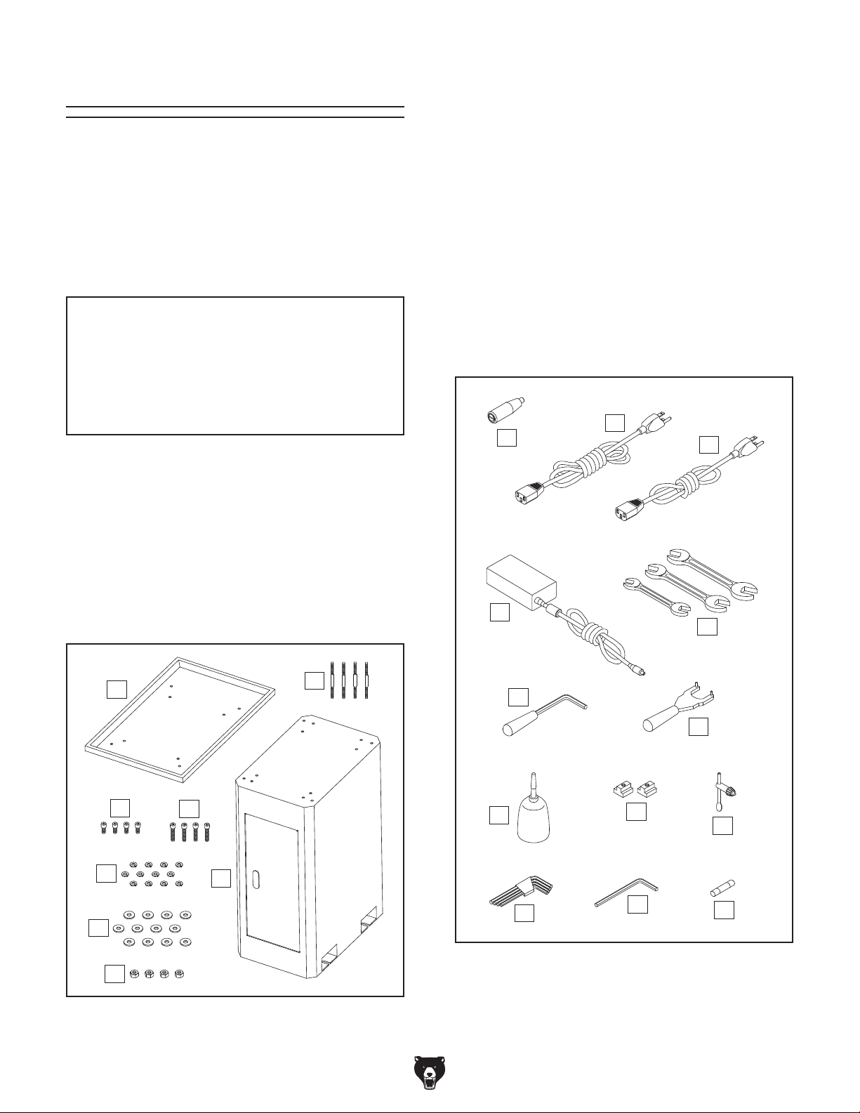
Box (Figure 10) Qty
A. Chi p Tray .................................................... 1
B. Studs M8-1.25 x 36, 101............................. 4
C. Cap Screws M8-1.25 x 10 .......................... 4
D. Cap Screws M8-1.25 x 30 .......................... 4
E. Lock Washers 8mm ................................. 12
F. Flat Washers 8mm ................................... 12
G. Hex Nuts M8-1.25 ....................................... 4
H. Stand .......................................................... 1
Crate (Figure 11) Qty
I. X-Axis Handwheel Handle (G0982 Only) ... 1
J. Power Cord for Mill/Drill 16AWG 72" .......... 1
K. Power Adapter Power Cord 18AWG 55"
(G0983 Only) .............................................. 1
L. Power Adapter (G0983 Only) ..................... 1
M. Open-End Wrenches 8 x 10, 14 x 17,
17 x 19mm ............................................1 Ea.
N. Drawbar Lock Lever ................................... 1
O. Spindle Spanner Wrench ........................... 1
P. Oil Bottle ..................................................... 1
Q. T-Slot Nuts M12-1.75 .................................. 2
R. Drill Chuck Key ........................................... 1
S. Hex Wrench 4-Pc. Set (3, 4, 5, 6mm) ........ 1
T. Hex Wrench 8mm ....................................... 1
U. Fuse 15A 250V (Spare) .............................. 1
J
I
L
K
M
A
C
E
F
-18-
G
D
H
Figure 10. Box inventory.
B
N
O
P
S
Figure 11. Crate inventory.
Model G0982/G0983 (Mfd. Since 01/24)
Q
R
T
U

Hardware Recognition Chart
USE THIS CHART TO MATCH UP
HARDWARE DURING THE INVENTORY
AND ASSEMBLY PROCESS.
Flat
Head
Cap
Screw
5mm
Model G0982/G0983 (Mfd. Since 01/24)
5mm
-19-
Cleanup
parts of the
The unpainted surfaces of your machine are
coated with a heavy-duty rust preventative that
prevents corrosion during shipment and storage.
This rust preventative works extremely well, but it
will take a little time to clean.
Be patient and do a thorough job cleaning your
machine. The time you spend doing this now will
give you a better appreciation for the proper care
of your machine's unpainted surfaces.
There are many ways to remove this rust preventative, but the following steps work well in a wide
variety of situations. Always follow the manufac-
turer’s instructions with any cleaning product you
use and make sure you work in a well-ventilated
area to minimize exposure to toxic fumes.
Before cleaning, gather the following:
• Disposable rags
• Cleaner/degreaser (WD•40 works well)
• Safety glasses & disposable gloves
• Plastic paint scraper (optional)
Basic steps for removing rust preventative:
1.
2.
3.
4.
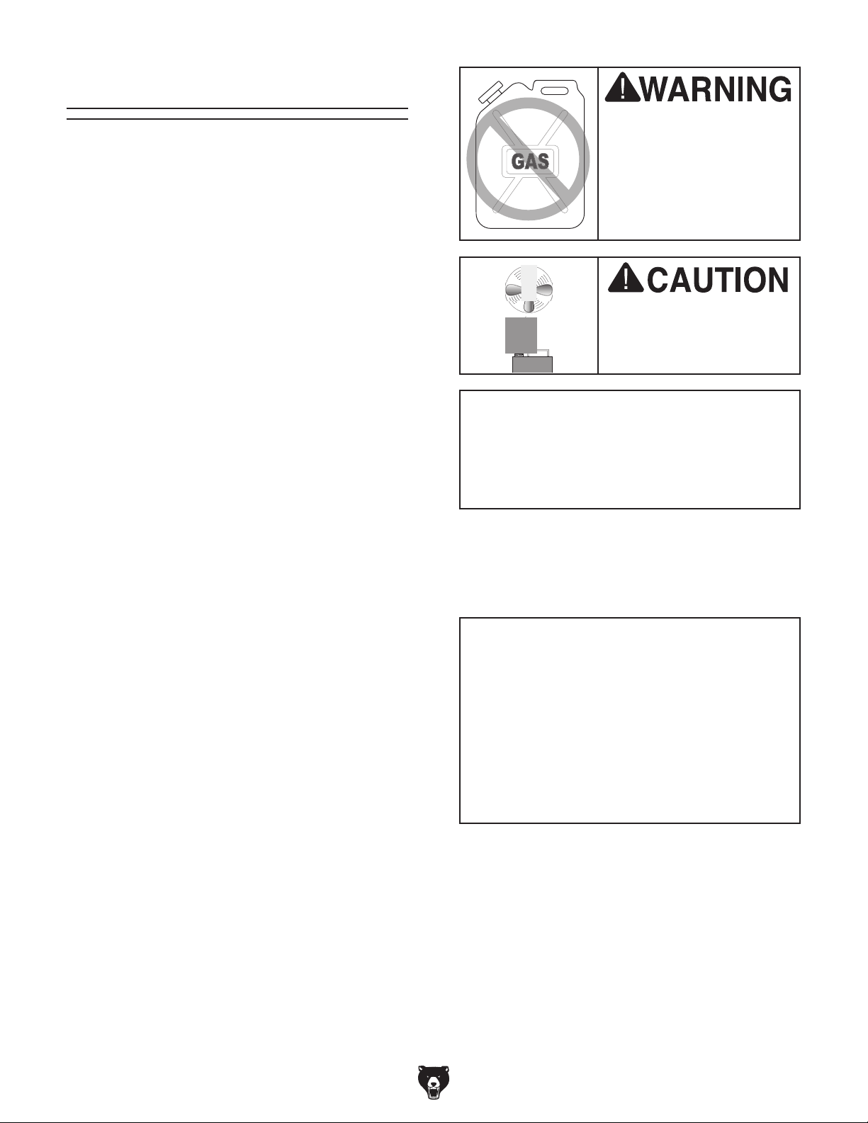
Many cleaning solvents
work in a well-ventilated
Cleanup
Gasoline and petroleum
products have low flash
points and can explode
or cause fire if used to
clean machinery. Avo id
using these products
to clean machinery.
Put on safety glasses.
Coat the rust preventative with a liberal
amount of cleaner/degreaser, then let it soak
for 5–10 minutes.
Wipe off the surfaces. If your cleaner/degreas-
er is effective, the rust preventative will wipe
off easily. If you have a plastic paint scraper,
scrape off as much as you can first, then wipe
off the rest with the rag.
are toxic if inhaled. Only
area.
NOTICE
Avoid harsh solvents like acetone or brake
parts cleaner that may damage painted surfaces. Always test on a small, inconspicuous location first.
T23692—Orange Power Degreaser
A great product for removing the waxy shipping grease from the non-painted
machine during clean up.
Order online at
www.grizzly.com
OR
Call 1-800-523-4777
Repeat Steps 2–3 as necessary until clean,
then coat all unpainted surfaces with a quality
metal protectant to prevent rust.
-20-
Figure 12. T23692 Orange Power Degreaser.
Model G0982/G0983 (Mfd. Since 01/24)

Site Considerations
Weight Load
Refer to the
of your machine. Make sure that the surface upon
which the machine is placed will bear the weight
of the machine, additional equipment that may be
installed on the machine, and the heaviest workpiece that will be used. Additionally, consider the
weight of the operator and any dynamic loading
that may occur when operating the machine.
Space Allocation
Consider the largest size of workpiece that will
be processed through this machine and provide
enough space around the machine for adequate
operator material handling or the installation of
auxiliary equipment. With permanent installations,
leave enough space around the machine to open
or remove doors/covers as required by the maintenance and service described in this manual.
See below for required space allocation.
Physical Environment
The physical environment where the machine is
operated is important for safe operation and longevity of machine components. For best results,
operate this machine in a dry environment that is
free from excessive moisture, hazardous chemicals, airborne abrasives, or extreme conditions.
Extreme conditions for this type of machinery are
generally those where the ambient temperature
range exceeds 41°–104°F; the relative humidity
range exceeds 20%–95% (non-condensing); or
the environment is subject to vibration, shocks,
Place this machine near an existing power source.
Make sure all power cords are protected from
traffic, material handling, moisture, chemicals, or
other hazards. Make sure to leave enough space
around machine to disconnect power supply or
Lighting around the machine must be adequate
enough that operations can be performed safely.
Shadows, glare, or strobe effects that may distract
or impede the operator must be eliminated.
Machine Data Sheet for the weight
or bumps.
Electrical Installation
Children or untrained people
may be seriously injured by
this machine. Only install in an
access restricted location.
55"
G0982
apply a lockout/tagout device, if required.
Lighting
Wall
26½"
64"
G0983
Electrical
=
Connection
= Min. 30"
Figure 13. Minimum working clearances.
Model G0982/G0983 (Mfd. Since 01/24)
-21-

Assembly
The machine must be fully assembled before it
can be operated. Before beginning the assembly
process, refer to
and gather
all
To ensure the assembly process
goes smoothly, first clean any
ered or coated in heavy-duty rust preventative (if
applicable).
Needed for Setup
listed items.
parts that are cov-
To assemble machine:
1. Place machine pallet near final machine
mounting location.
Place stand in desired location.
2.
3. Attach chip tray to stand with (4) M8-1.25 x
10 cap screws, 8mm lock washers, and 8mm
flat washers (see Figure 14). Hand-tighten
fasteners for now.
5.
Position lifting sling under headstock (see
Figure 15), and connect sling ends to forklift.
Note: DO NOT place sling over any controls
or against any components that may be damaged from force required for lifting.
Lifting Sling
x 4
Chip Tray
Stand
Cabinet
Figure 14. Chip tray attached to stand.
4. Fully tighten X-axis, Y-axis, and Z-axis lock
handles (see Figures 5–6 on Pages 5–6).
Figure 15. Example of lifting sling positioned
under headstock.
HEAVY LIF T!
Straining or crushing injury
may occur from improperly
lifting machine or some of
its parts. To reduce this risk,
get help from other people
and use a forklift (or other
lifting equipment) rated for
weight of this machine.
-22-
Model G0982/G0983 (Mfd. Since 01/24)
6. Unbolt machine from pallet.
Anchoring machinery to the floor prevents tipping
or shifting and reduces vibration that may occur
during operation, resulting in a machine that runs
slightly quieter and feels more solid.
If the machine will be installed in a commercial or
workplace setting, or if it is permanently connected (hardwired) to the power supply, local codes
may require that it be anchored to the floor.
If not required by any local codes, fastening the
machine to the floor is an optional step. If you
choose not to do this with your machine, we recommend placing it on machine mounts, as these
provide an easy method for leveling and they have
vibration-absorbing pads.
7. With assistant to steady machine to prevent
it from swinging, carefully lift machine and
place it onto stand (see Figure 16), then
remove lifting sling.
Attach machine to stand with (4) M8-1.25 x
8.
30 cap screws, 8mm lock washers, and 8mm
flat washers (see Figure 16).
G0982 Only: Thread X-axis handwheel han-
9.
dle into X-axis handwheel (see Figure 16).
Anchoring to Floor
Number of Stand Mounting Holes ................. 4
Diameter of Stand Mounting Holes
............1⁄2"
x 4
Figure 16. Machine attached to stand (G0982
shown).
10.
Fully tighten fasteners from Step 3.
X-Axis
Handwheel
Handle
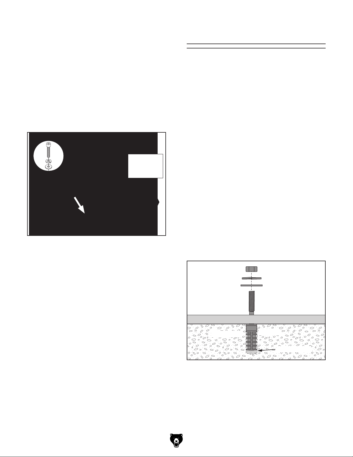
Four sets of mounting fasteners—including a
stud, flat washer, lock washer, and hex nut—have
been provided to attach to your stand. How you
anchor these fasteners to the floor will depend on
the type of shop floor you have. See Figure 17 for
an example of how to mount the stand to a concrete floor with the included mounting fasteners.
Hex Nut
Lock Washer
Flat Washer
Stud
Stand Base
Model G0982/G0983 (Mfd. Since 01/24)
Concrete
Figure 17. Anchoring machinery to concrete
floor with included hardware.
Anchors are a popular way to anchor machinery
to a concrete floor, because the anchors sit flush
with the floor surface, making it easy to unbolt
and move the machine later, if needed. However,
any time local codes apply, you MUST follow the
anchoring methodology specified by the code.
Anchor
Drilled Hole
-23-

Power Connection
Before the machine can be connected to the
power source, an electrical circuit and connection device must be prepared per the POWER
SU PPLY section in this manual, and all previous setup instructions in this manual must be
complete to ensure that the machine has been
assembled and installed properly.
To connect machine to power:
Press Emergency Stop button (see Figure 18).
1.
3.
G0983 Only: Connect 16AWG power adapt-
er cord to power feed socket (see Figure 20).
G0983 Only: Connect 18AWG power adapt-
4.
er power cord to male receptacle on power
adapter (see Figure 20).
Power
Male
Receptacle
Figure 20. Power adapter connected to power
16AWG Power
Adapter Cord
18AWG
Power Adapter
Power Cord
feed and power cord.
Feed
Socket
Emergency
Stop Button
Figure 18. Location of Emergency Stop button
(G0982 shown).
2. Connect 16AWG mill/drill power cord to male
receptacle on column (see Figure 19).
Male
Receptacle
16AWG Mill/Drill
Power Cord
5.
Insert mill/drill power cord plug into matching
power supply receptacle.
G0983 Only: Insert power adapter plug into
6.
matching power supply receptacle.
Figure 19. Power cord connected to mill/drill.
-24-
Model G0982/G0983 (Mfd. Since 01/24)

Test Run
Once assembly is complete, test run the machine
to ensure it is properly connected to power and
safety components are functioning correctly.
If you find an unusual problem during the test run,
immediately stop the machine, disconnect it from
power, and fix the problem BEFORE operating the
machine again. The
table in the
SERVICE section of this manual can help.
DO NOT start machine until all preceding
setup instructions have been performed.
Operating an improperly set up machine
ed results that can lead to serious injury,
Serious injury or death can result from
Troubleshooting
The Test Run consists of verifying the following:
1) The motor powers up and runs correctly, 2) the
Emergency Stop button disables the spindle properly, 3) the chuck guard safety switch disables the
spindle properly, and 4) the spindle and power
feed controls work correctly.
2. Press Emergency Stop button in (see
Figure 21).
Turn spindle speed dial (see Figure 21) all
3.
the way counterclockwise. This will prevent
spindle from starting at a high speed.
Spindle
Speed
Dial
Emergency
Stop Button
Figure 21. Spindle control panel (G0982 shown).
Start/Stop
Button
using this machine BEFORE understanding
its controls and related safety information.
DO NOT operate, or allow others to operate,
machine until the information is understood.
may result in malfunction or unexpect-
death, or machine/property damage.
To test run machine:
Clear all setup tools away from machine.
1.
Make sure cords are well clear of table movement and potential direction of travel.
4. Twist Emergency Stop button clockwise until
it springs out (see Figure 22). This resets
switch so spindle can start.
I
S
W
T
T
Emergency Stop Button
Figure 22. Resetting Emergency Stop button.
5. Press Start/Stop button (see Figure 21) to
start spindle rotation. Verify motor starts up
and runs smoothly without any unusual problems or noises.
Model G0982/G0983 (Mfd. Since 01/24)
Slowly turn spindle speed dial clockwise to
6.
test variable-speed, then turn it all the way
counterclockwise.
-25-

7. Press Emergency Stop button to stop spindle
rotation.
WITHOUT resetting Emergency Stop button,
8.
try to start spindle rotation by pressing ON
button. Spindle should not rotate.
— If spindle does not rotate, safety feature
of Emergency Stop button is working correctly. Proceed to Step 9.
— If spindle does rotate, immediately turn
machine OFF and disconnect power.
Safety feature of Emergency Stop button is NOT working properly and must be
replaced before further using machine.
Reset Emergency Stop button.
9.
10. Press Start/Stop button to start spindle
rotation.
While being careful to avoid rotating chuck
13.
and spindle, pivot chip guard forward and
away from chuck (see Figure 24). Spindle
will stop rotating and "Err" will blink on spindle
speed DRO.
— If spindle does not stop, immediately
turn machine OFF and disconnect power.
Safety feature of chip guard safety switch
is NOT working properly and must be
replaced before further using machine.
Spindle
Speed
DRO
Press Reverse button (see Figure 23) to
11.
reverse spindle rotation. Reverse button will
illuminate and spindle rotation icon (see
Figure 23) will change to display counterclockwise rotation. Verify motor changes
directions and starts up and runs smoothly
without any unusual problems or noises.
Spindle
Rotation
Icon
Reverse
Button
Figure 23. Location of Reverse button and
spindle rotation icon.
12. Slowly turn spindle speed dial clockwise
to test variable-speed for counterclockwise
direction, then turn it all the way counterclockwise.
Chip
Guard
Figure 24. Chip guard pivoted away from chuck.
WITHOUT pivoting chip guard back in place,
14.
press Start/Stop button once to reset it, then
try to start spindle rotation by pressing Start/
Stop button.
— If spindle does not rotate, safety feature of
chip guard is working correctly. Proceed to
Step 15.
— If spindle does rotate, immediately turn
machine OFF and disconnect power.
Safety feature of chip guard is NOT working properly and must be replaced before
further using machine.
Pivot chip guard back into place.
15.
16. Press Reverse button and Start/Stop button
to reset them.
— G0982: Test Run is complete! Complete
Spindle Break-In on Page 28 before
proceeding with operations.
-26-
— G0983: Proceed to Step 17 to complete
Test Run for power feed components.
Model G0982/G0983 (Mfd. Since 01/24)

17. Read Controlling Table Travel section,
beginning on Page 32, to understand
function of power feed, table locks, and limit
stops.
Turn power feed speed control dial (see
18.
Figure 25) all the way counterclockwise to
prevent high-speed startup.
Move direction switch (see Figure 25) to neu-
19.
tral (middle) position.
22. Turn leadscrew selector knob 90º clockwise
to engage power feed drive gear.
Note: If selector knob does not turn the full
90º, drive gear is not aligned with X-axis
leadscrew threads. Engage and turn X-axis
handwheel (see Figure 26) until knob can be
turned fully, then disengage handwheel.
Turn leadscrew selector knob (see Figure
20.
25) counterclockwise to disengage power
feed drive gear.
Speed
Direction
Switch
Indicator
Figure 25. Left X-axis power feed components.
21. Loosen X-axis lock handle (see Figure 26).
Fault
Control
Dial
Leadscrew
Selector Knob
X-Axis
Handwheel
During power feed operation, X-axis handwheel
handle will spin rapidly if
it is pressed in or accidentally engaged. Always stay
clear of handle when using
power feed. Failure to do
so could lead to entanglement or impact injuries.
23. Move direction switch to left position.
24. Turn speed control dial clockwise to turn
power feed ON, then gradually increase
speed to confirm that table is moving left.
Watch for table limit stop to engage limit
25.
switch (see Figure 26). When it engages,
fault indicator light should illuminate (see
Figure 25) and motor should stop. If power
feed does not stop, turn speed control dial all
the way counterclockwise and move direction
switch to middle (OFF) position.
— If fault indicator light illuminates and power
feed stops, power feed limit switch is
working correctly. Proceed to Step 26.
Table Limit
X-Axis
Lock Handle
Figure 26. Right X-axis table controls.
Model G0982/G0983 (Mfd. Since 01/24)
Stop
(1 of 2)
— If fault indicator does not illuminate, or
power feed does not stop, fault indicator
light or power feed limit switch is not working correctly. Immediately turn power feed
OFF and disconnect power. Contact Tech
Support before continuing with Test Run.
Turn speed control dial all the way counter-
26.
clockwise and move direction switch to neutral position to correct fault mode.
-27-

27. Move direction switch through neutral (middle) position and to right position.
Turn speed control dial clockwise to turn
28.
power feed ON. Table should begin moving
right.
Confirm that table stops moving when table
29.
limit stop presses against limit switch.
— If fault indicator light illuminates and power
feed stops, power feed limit switch is
working correctly. Proceed to Step 30.
— If fault indicator does not illuminate, or
power feed does not stop, fault indicator
light or power feed limit switch is not working correctly. Immediately turn power feed
OFF and disconnect power. Contact Tech
Support before continuing with Test Run.
Move direction switch to neutral (middle)
30.
position and turn speed control dial all the
way counterclockwise. Test Run is complete!
Complete Spindle Break-In before proceeding with operations.
Complete spindle bearing break-in procedure to prevent rapid wear and tear of spindle components once machine is placed
into operation.
To perform spindle break-in:
Make sure spindle area is free of obstructions.
1.
2. Press Start/Stop button (see Figure 27) to
start spindle rotation.
Spindle
Speed
Dial
Figure 27. Spindle control panel (G0982 shown).
Reverse
Button
Start/Stop
Button
Spindle Break-In
The spindle break-in procedure distributes lubrication throughout the bearings to reduce the risk
of early bearing failure if there are any "dry" spots
or areas where lubrication has settled in the bearings. You must complete this procedure before
placing operational loads on the spindle for the
first time when the machine is new or if it has been
sitting idle for longer than 6 months.
Always start the spindle break-in at the lowest
speed to minimize wear if there are dry spots.
Allow the spindle to run long enough to warm up
and distribute the bearing grease, then incrementally increase spindle speeds and repeat this process at each speed until reaching the maximum
spindle speed. Following the break-in procedure
in this progressive manner helps minimize any
potential wear that could occur before lubrication
is fully distributed.
Allow spindle to run clockwise (as viewed
3.
from above) at about 100 RPM for 10 minutes.
Press Reverse button (see Figure 27) and
4.
allow spindle to run counterclockwise (as
viewed from above) at about 100 RPM for
another 10 minutes.
Use spindle speed dial (see Figure 27) to
5.
adjust spindle to about 200 RPM, then run
spindle in either direction for 10 minutes.
Repeat Step 5 for each speed listed below in
6.
progressive order:
a. 500 RPM
b. 1000 RPM
c. 2000 RPM
7. Press Start/Stop button to stop spindle
rotation. Congratulations! Spindle break-in is
now complete.
-28-
Model G0982/G0983 (Mfd. Since 01/24)

SECTION 4: OPERATIONS
The purpose of this overview is to provide the
novice machine operator with a basic understanding of how the machine is used during operation,
so the
discussed
later in this manual
Due to the generic nature of this overview, it is
not intended to be an instructional guide. To learn
more about specific operations, read this entire
manual,
training from experienced
machine operators, and do additional research
outside of this manual by reading "how-to" books,
trade magazines, or websites.
To reduce your risk of
serious injury, read this
entire manual BEFORE
ing loss can occur while operating this
Keep hair, clothing, and
ing parts at all times.
Entanglement can result
in death, amputation, or
Operation Overview
machine controls/components
are easier to understand.
seek additional
To complete a typical operation, the operator
does the following:
Examines the workpiece to make sure it is
1.
suitable for milling/drilling.
Securely clamps workpiece to table.
2.
3. With machine disconnected from power,
installs correct tooling.
Adjusts headstock height above table.
4.
5. Puts on personal protective equipment.
6. Connects machine to power.
7. Starts spindle rotation and sets correct spin-
dle speed for operation.
Uses downfeed and table controls to perform
8.
operation.
using machine.
Eye injuries, respiratory problems, or hear-
tool. Wear personal protective equipment
to reduce your risk from these hazards.
Model G0982/G0983 (Mfd. Since 01/24)
jewelry away from mov-
severe crushing injuries!
Waits for spindle to completely stop before
9.
removing workpiece.
Disconnects machine from power before
10.
changing/removing tooling.
If you are not experienced with this type
of machine, WE STRONGLY RECOMMEND
that you seek additional training outside of
this manual. Read books/magazines or get
formal training before beginning any projects. Regardless of the content in this section, Grizzly Industrial will not be held liable
for accidents caused by lack of training.
-29-

Using
Spindle Downfeed
Spindle downfeed movement on the mill/drill is
controlled by the coarse downfeed lever or the
fine downfeed knob.
Use Figures 28–29 and the following descriptions
to become familiar with the spindle downfeed
controls.
A. Spindle Depth DRO: Shows depth of
spindle downfeed in inches or millimeters.
Measurement can be set to zero at any point
along spindle travel.
. Fine Downfeed Knob: Manually controls
B
rate of fine spindle downfeed.
. Coarse Downfeed Handle (1 of 3): Manually
C
controls quick spindle downfeed.
Downfeed Selector Handle: Tighten to use
D.
spindle with fine downfeed knob. Loosen to
use spindle with coarse downfeed handles.
B
A
Figure 28. Right spindle downfeed components
(G0982 shown).
C
D
. Quill Lock Screw: Secures quill in place for
E
increased stability during operations. Use
supplied quill lock lever to loosen and tighten
quill.
Using Coarse Downfeed
Coarse downfeed is typically used for drilling,
because it allows you to quickly lower the spindle
with varying speed/pressure, and it automatically retracts the spindle to the top position when
released.
Note: To maintain control of the upward spindle
travel and the rotating bit in your workpiece,
always continue holding the handle until the spindle returns to the top position. Letting go of the
handle too soon will cause the spindle to retract
too quickly and slam up into the headstock.
To use coarse downfeed:
Loosen downfeed selector handle to engage
1.
coarse downfeed handles (see Figure 28).
E
Figure 29. Left spindle downfeed components
(G0982 shown).
-30-
2. Loosen quill lock with quill lock lever (see
Figure 29).
Turn spindle depth DRO ON and zero it out.
3.
Use coarse downfeed handles to raise and
4.
lower spindle while referencing spindle depth
DRO for precise movement.
Model G0982/G0983 (Mfd. Since 01/24)

Using Fine Downfeed
To engage the fine downfeed, turn the downfeed
selector handle clockwise until tightened. When
fine downfeed is engaged, the spindle only moves
up or down when the fine downfeed knob is rotated (there is no automatic spindle return to the top
position, as with the coarse downfeed controls).
This manual level of control makes it easy to precisely lock the spindle depth in place with the quill
lock lever when milling a flat surface across the
face of a workpiece, to ensure the spindle depth
does not move until the entire milling operation is
complete.
The fine downfeed knob allows for a precise
amount of material to be removed from the
workpiece (see Figure 30).
Spindle
Depth
DRO
Fine
Downfeed
Knob
4. Rotate fine downfeed knob clockwise and
lower cutting tool so it just touches workpiece.
Move workpiece out of the way, using X/Y-
5.
axis table handwheels.
Using spindle depth DRO to gauge spindle
6.
movement, rotate fine downfeed knob clockwise until DRO displays 0.010" of movement.
Tighten quill lock with quill lock lever.
7.
8. Turn spindle speed dial clockwise, adjust
speed as appropriate, and perform milling
operation by moving workpiece under cutting
tool with X/Y-axis table handwheels.
Using Spindle Depth DRO
1. Press OFF/ON button (see Figure 31). A
reading should appear on display.
Press mm/inch button (see Figure 31) to tog-
2.
gle display between inches and millimeters.
Downfeed
Selector
Handle
Figure 30. Fine spindle downfeed components
(G0982 shown).
In the following example, the fine downfeed
controls are used to mill 0.010" off a workpiece:
Adjust headstock on Z-axis so cutting tool is
1.
just above workpiece surface, then secure
headstock.
Tighten downfeed selector handle (see
2.
Figure 30) to engage fine downfeed knob.
Press ZERO button (see Figure 31) to "zero"
3.
readout at any point along spindle travel.
Current reading will be cleared and scale will
reset to 0.00.
mm/inch
Button
OFF/ON
Button
Figure 31. Spindle depth DRO.
Press OFF/ON button when operation is
4.
complete to conserve battery.
ZERO
Button
Loosen quill lock with quill lock lever.
3.
Model G0982/G0983 (Mfd. Since 01/24)
-31-

Controlling
Table Travel
The table travels in two directions, as illustrated
in Figure 32:
The table handwheels have graduated dials in
0.001" increments, with one full revolution equalling 0.10".
The table travel is adjusted with the handwheels
on the front and side of the table (see Figure 33).
The X-axis handwheel is spring-loaded. Press it in
while turning to engage the leadscrew.
• X-axis (longitudinal)
• Y- axis (cross)
Y-Axis or
Cross Travel
(In & Out)
X-Axis or Longitudinal Travel
(Left & Right)
Figure 32. Directions of table movement.
Both the X- and Y-axes feature table locks (see
Figure 33). To ensure unexpected movement of
the table does not occur during precision operations, use these locks to secure the table along
any axis that should not move for any given
operation.
On the Model G0983, turn the leadscrew selector
knob counterclockwise to disengage the power
feed drive gear in order to move the table with the
X-axis handwheel.
G0983 Power Feed
On the Model G0983, the X-axis table travel
can also be controlled with the power feed (see
Figure 34).
Use the leadscrew selector knob (see Figure 34)
to engage or release the power feed drive gear.
Adjustable limit stops and a limit switch (see
Figure 34) control the power feed travel.
Power Feed
Power
Feed
Limit Switch
Y-Axis
Handwheel
X-Axis
Lock Handle
Figure 33. Location of manual table controls
(G0982 shown).
-32-
Y-Axis
Lock Handle
X-Axis
Handwheel
Limit
Limit
Leadscrew
Selector
Knob
Figure 34. X-axis power feed components.
Model G0982/G0983 (Mfd. Since 01/24)
Stop
During power feed operation, X-axis handwheel
handle will spin rapidly if
it is pressed in or accidentally engaged. Always stay
clear of handle when using
power feed. Failure to do
so could lead to entanglement or impact injuries.
Stop

The power feed rate is variable from 4–14 in./min.
(100–300 mm/min.). Turn the speed control dial
clockwise to turn the power feed ON and adjust
the speed (see Figure 35).
Direction
Switch
Figure 35. Power feed controls.
Speed
Control
Fault
Indicator
Dial
Leadscrew
Selector Knob
There is no separate power switch for power
feed. Turn speed control dial all the way counterclockwise, and make sure power cords
and other wires do not interfere with table
movement before connecting power feed to
power.
6. Loosen X-axis lock handle (see Figure 33 on
Page 32).
Turn leadscrew selector knob 90º clockwise
7.
to engage power feed drive gear.
Note: If selector knob does not turn the full
90º, drive gear is not aligned with X-axis
leadscrew threads. Engage and turn X-axis
handwheel (see Figure 35) until knob can be
turned fully, then disengage handwheel.
To use power feed:
Adjust location of table travel limit stops
1.
to suit workpiece (see Figure 34 on Page
32). Lock stops in position.
Turn power feed speed control dial (see
2.
Figure 35) all the way counterclockwise.
Move direction switch (see Figure 35) to neu-
3.
tral (middle) position.
Turn leadscrew selector knob (see Figure
4.
35) counterclockwise to disengage power
feed drive gear.
Connect power feed to provided 5A power
5.
supply and grounded 5-15 outlet. Power light
will illuminate.
Turn speed control dial clockwise to turn
8.
power feed ON (see Figure 35).
Use direction switch and speed control dial to
9.
move table to desired position. Move direction switch to neutral (middle) position to stop
power feed and table movement.
If necessary, turn leadscrew selector knob
10.
counterclockwise and use X-axis handwheel
to make fine adjustments to table location.
11. If fault indicator
power feed has exceeded table travel limit or
reached an obstruction. Eliminate fault condition by turning speed control dial to "0" position and moving direction switch to neutral
(middle) position.
(see Figure 35)
illuminates,
Model G0982/G0983 (Mfd. Since 01/24)
-33-

Adjusting Headstock
5. Attempt to separate drill chuck and arbor by
hand —if they separate, repeat Steps 3–4.
The headstock can be adjusted up and down the
column (Z-axis) and has a dovetailed slide that
allows users to reposition the headstock or change
tooling without losing workpiece alignment with a
hole or milling path. The Z-axis handwheel has a
graduated dial that is in 0.0005" increments, with
one full revolution equalling 0.05".
To adjust headstock:
Joining New Drill
Chuck & Arbor
An arbor and drill chuck come pre-installed on this
machine. The following procedure describes how
to install a new chuck in the case that you want a
different chuck in the future. As it is very difficult to
separate an existing chuck and arbor assembly,
we recommend obtaining a new arbor and joining
the two together.
1. DISCONNECT MACHINE FROM POWER!
Loosen Z-axis lock handle shown in
2.
Figure 36.
Z-Axis
Lock Handle
Figure 36. Location of Z-axis lock handle
(G0983 shown).
. Use Z-axis handwheel (see Figure 37) to
3
adjust headstock height, then tighten Z-axis
lock handle.
Items Needed Qty
Acetone or Lacquer Thinner .............. As Needed
New Chuck
New Arbor
Block of Wood
To join new drill chuck and arbor:
1. Use acetone or lacquer thinner to clean drill
chuck and arbor mating surfaces, especially
bore.
2. Retract chuck jaws completely into chuck.
3. Insert small end of arbor into chuck.
4. Hold assembly by arbor and tap chuck onto
block of wood with medium force, as illustrated below.
........................................................ 1
......................................................... 1
................................................... 1
Z-Axis
Handwheel
Figure 37. Location of Z-axis handwheel (G0982
shown).
-34-
Figure 38. Tapping drill chuck/arbor on block of
wood.
Model G0982/G0983 (Mfd. Since 01/24)

Removing/Installing
Tooling
Note: There is a hole in top of drawbar cap
to allow access to drawbar and to perform
following steps without removing cap.
This machine features an R8 spindle taper and
requires R8 tooling. R8 tooling arbors are secured
in position from the top end with a drawbar and
feature a keyway for easy alignment.
Before installation, always ensure the tapered
surfaces of the arbor and spindle are completely
clean and free of any dust, debris, or lint. This will
help ensure proper fit and accurate cutting results.
Keyway
R8 Arbor
Figure 39. Drill chuck joined with R8 arbor.
Drawbar
Cap
Figure 40. Location of drawbar cap.
Use drawbar lock lever or 8mm hex wrench in
3.
top of drawbar and spindle spanner wrench in
holes in bottom of spindle to loosen drawbar
(see Figure 41).
Top of
Drawbar
Cutting tools are sharp and
can easily cause laceration
injuries. Always protect
your hands with leather
gloves or shop rags when
handling cutting tools.
The R8 arbor supports a wide range of tools, such
as machining arbors, end-mill holders, and fly cutters for cutting operations.
Tools Needed Qty
Drawbar Lock Lever .......................................... 1
Spindle Spanner Wrench
Brass-Head or Dead-Blow Hammer
.................................. 1
.................. 1
Removing Tooling
1.
DISCONNECT MACHINE FROM POWER!
2. Unscrew drawbar cap to remove (see
Figure 40).
Spindle
Holes
Spindle
Spanner Wrench
Figure 41. Example of loosening drawbar.
DO NOT completely unscrew drawbar before
striking it with hammer in following step.
You will damage threads on drawbar and
arbor.
Model G0982/G0983 (Mfd. Since 01/24)
-35-

4. Tap top of drawbar with brass-head or deadblow hammer to unseat taper, as shown in
Figure 42.
Determining
Spindle Speed
Drawbar
Figure 42. Example of using hammer to loosen
drawbar.
Hold onto tooling with one hand and fully
5.
unthread drawbar with other hand.
Installing Tooling
1. DISCONNECT MACHINE FROM POWER!
2. Clean debris or oily substances from inside
spindle taper and tooling mating surface.
Using the correct spindle speed is important for
safe and satisfactory results, as well as maximizing tool life.
Many variables affect the optimum spindle speed
to use for any given operation, but the two most
important are the recommended cutting speed
for the workpiece material and the diameter of
the cutting tool, as noted in the formula shown in
Figure 43.
*Recommended
Cutting Speed (FPM) x 12
Tool Dia. (in inches) x 3.14
Spindle
=
Speed
(RPM)
*Double if using carbide cutting tool
Figure 43. Spindle speed formula for mill/drills.
Cutting speed, typically defined in feet per minute
(FPM), is the speed at which the edge of a tool
moves across the material surface.
Align keyway of tool arbor with protruding pin
3.
inside spindle taper, and firmly push arbor
into spindle to seat it.
With one hand holding tool in place, insert
4.
drawbar into spindle from top of headstock,
then thread it into tool by hand until snug.
Do not overtighten drawbar. Overtightening
makes tool removal difficult and may damage arbor and threads.
5. Use drawbar lock lever or 8mm hex wrench in
top of drawbar and spindle spanner wrench in
holes in bottom of spindle to tighten drawbar
(see Figure 41 on Page 35).
Install drawbar cap.
6.
A recommended cutting speed is an ideal speed
for cutting a type of material in order to produce
the desired finish and optimize tool life.
The books Machinery’s Handbook or Machine
Shop Practice, and some internet sites, provide excellent recommendations for which cutting
speeds to use when calculating the spindle speed.
These sources also provide a wealth of additional
information about the variables that affect cutting
speed and they are a good educational resource.
Also, there are many spindle-speed calculators on
the internet. These sources will help you consider
the applicable variables in order to determine the
best spindle speed for the operation.
-36-
Model G0982/G0983 (Mfd. Since 01/24)

SECTION 5: ACCESSORIES
Installing unapproved accessories may
order online at www.grizzly.com or call 1-800-523-4777
cause machine to malfunction, resulting in
serious personal injury or machine damage.
To reduce this risk, only install accessories
recommended for this machine by Grizzly.
NOTICE
Refer to our website or latest catalog for
additional recommended accessories.
T25615—Milling for Home Machinists
This is a project-based course book that provides
a complete introduction to milling and the use of
the milling machine. It assumes no prior knowledge and works through the process of using a
home shop mill from beginning to end.
G2861—Face Mill
G4051—Replacement Carbide Inserts
This 2
(included) and comes with an R8 arbor. It takes a
7
1
⁄2 " Face Mill accepts four carbide inserts
⁄16 "-20 drawbar.
Figure 45. G2861 Face Mill.
Figure 44. T25615 Milling for Home Machinists.
T26485—58-Pc. Clamping Kit
This clamping kit includes: (24) studs (four studs
each: 3", 4", 5", 6", 7", and 8" long), (6) step block
pairs, (6) T-nuts, (6) flange nuts, (4) coupling nuts,
and (6) end hold-downs. Set fits
includes
wall or side of machine for easy access.
3
⁄8"-16 studs. Racks can be bolted to the
Figure 46. T26485 58-Pc. Clamping Kit.
7
⁄16 " T-slots and
Model G0982/G0983 (Mfd. Since 01/24)
-37-

SECTION 6: MAINTENANCE
To reduce risk of shock or
accidental startup, always
disconnect machine from
Cleaning &
Protecting
power before adjustments,
maintenance, or service.
Schedule
For optimum performance from this machine, this
maintenance schedule must be strictly followed.
Ongoing
To minimize your risk of injury and maintain proper
machine operation, shut down the machine immediately if you ever observe any of the items below,
and fix the problem before continuing operations:
• Loose mounting bolts.
• Damaged tooling.
Worn or damaged wires.
•
Debris or built-up grime on machine.
•
Any other unsafe condition.
•
Daily Maintenance
• Lubricate table and column ways (Page 39).
• Lubricate quill surface (Page 40).
Metal chips left on the machine that have been
soaked with water-based coolant will invite oxidation and a gummy residue build-up around the
moving parts. Use a brush and shop vacuum to
remove chips and debris from the working surfaces of the mill/drill. Never blow off the mill/drill
with compressed air, as this will force metal chips
deep into the mechanisms and may cause injury
to yourself or bystanders.
Remove any rust build-up from unpainted castiron surfaces of mill/drill and treat with a nonstaining lubricant after cleaning.
Keep unpainted cast-iron surfaces rust-free
with regular applications a quality metal protectant
(see Figure 47 for offerings from Grizzly).
Recommended Metal Protectants
G5562—SLIPIT® 1 Qt. Gel
G5563—SLIPIT
®
11 Oz . Spray
Weekly Maintenance
• Lubricate leadscrews (Page 40).
Semi-annual Maintenance
• Check belt for damage or wear (Page 41).
• Lubricate quill rack (Page 41).
-38-
Figure 47. Recommended products for
protecting unpainted cast iron/steel parts on
machinery.
Model G0982/G0983 (Mfd. Since 01/24)

Lubrication
This machine has numerous moving metal-tometal contacts that require regular and proper
lubrication to ensure efficient and long-lasting
operation, and to protect your investment.
Z-Axis
Way Cover
Other than the lubrication points covered in this
section, all other bearings are internally lubricated
and sealed at the factory. Simply leave them
alone unless they need to be replaced.
Before performing any lubrication task,
DISCONNECT MACHINE FROM POWER!
NOTICE
Recommended lubrication is based on
light-to-medium usage. Since lubrication
helps to protect value and operation of
machine, these lubrication tasks may need
to be performed more frequently than recommended, depending on usage.
Failure to follow reasonable lubrication
practices as instructed in this manual could
lead to premature failure of machine components and will void warranty.
Z-Axis
Way
Z-Axis
Way
Figure 48. Example of Z-axis way cover moved
to reveal ways.
Y-Axis Way
Y-Axis
Way Cover
Y-Axis Way
Table & Column Ways
Lube Type ............. SB1365 or ISO 68 Equivalent
Lube Amount
Lubrication Frequency
Items Needed Qty
Shop Rags ......................................... As Needed
Mineral Spirits
SB1365 or ISO 68 Equivalent
Phillips Head Screwdriver #2
Move way covers out of the way and clean X-, Y-,
and Z-axis ways (see Figures 48–50) with rags
and mineral spirits to remove grime and old lubrication. Wipe ways with recommended lubrication,
then move components back and forth several
times over full range of travel to spread lubricant
and ensure smooth movement.
........................................Thin Coat
........8 Hours of Operation
.................................... As Needed
............ As Needed
............................ 1
Figure 49. Example of Y-axis way cover moved
to reveal ways.
X-Axis Way
Figure 50. Location of X-axis ways (G0982
shown).
X-Axis Way
Model G0982/G0983 (Mfd. Since 01/24)
-39-

Quill Surface
Lube Type ............. SB1365 or ISO 68 Equivalent
Lube Amount
Lubrication Frequency
Items Needed Qty
Shop Rags ......................................... As Needed
Mineral Spirits
SB1365 or ISO 68 Equivalent
To lubricate quill surface:
Fully lower quill and lock in position.
1.
........................................Thin Coat
........8 Hours of Operation
.................................... As Needed
............ As Needed
Move way covers out of the way and clean X- , Yand Z-axis leadscrews (see Figures 52–54) with
brush and mineral spirits to remove grime and old
lubrication. Use clean brush to wipe leadscrew
teeth with recommended lubrication, then move
components back and forth several times over full
range of travel to spread lubricant.
Z-Axis
Way Cover
2. Without disturbing grease on quill rack, clean
outside smooth surface of quill with mineral
spirits and shop rags (see Figure 51).
Quill
Outside
Surface
Figure 51. Location of quill surface and rack.
When dry, apply thin coat of ISO 68 or
3.
equivalent oil to smooth surface, then move
spindle up and down to evenly distribute oil.
Quill
Rack
Z-Axis
Leadscrew
Figure 52. Example of Z-axis way cover moved
to reveal leadscrew.
Y-Axis
Leadscrew
Y-Axis
Way Cover
Figure 53. Example of Y-axis way cover moved
to reveal leadscrew.
Leadscrews
Lube Type ............. SB1365 or ISO 68 Equivalent
Lube Amount
Lubrication Frequency
Items Needed Qty
Stiff Brushes ...................................................... 2
Mineral Spirits
SB1365 or ISO 68 Equivalent
Phillips Head Screwdriver #2
-40-
........................................Thin Coat
......40 Hours of Operation
.................................... As Needed
............ As Needed
............................ 1
X-Axis
Leadscrew
Figure 54. Location of X-axis leadscrew (G0982
shown).
Model G0982/G0983 (Mfd. Since 01/24)

Quill Rack
Lube Type ............. T26419 or NLGI#2 Equivalent
Lube Amount
Lubrication Frequency
........................................Thin Coat
.....................6–12 Months
Checking/Replacing
Belt
Items Needed Qty
Shop Rags ......................................... As Needed
Mineral Spirits
Stiff Brush
T26419 or NLGI#2 Equivalent
To lubricate quill rack:
1. Lower quill to gain full access to quill rack
(see Figure 55). Lock in position.
.................................... As Needed
.......................................................... 2
........... As Needed
Quill
Rack
The belt transfers power from the motor to the
spindle. If the belt is worn or damaged in any
way, the mill/drill will not operate optimally, and
unnecessary wear on the moving parts will occur.
Inspect the belt regularly for damage or wear and
replace it if necessary.
Use care when handling belt as it could
pinch your fingers. It may also be hot
after extended use, so wait to touch belt if
machine has been in use.
Items Needed Qty
Phillips Head Screwdriver #2 ............................ 1
Hex Wrenches 2, 4, 8mm
Flat Head Screwdriver
Replacement Belt (#P0982502)
To check /replace belt:
............................ 1 Ea.
1
⁄4" .................................. 1
........................ 1
Figure 55. Location of quill rack.
2. Clean teeth with mineral spirits, shop rags,
and brush.
When dry, use clean brush to apply thin coat
3.
of grease to teeth and raise/lower quill several times to evenly distribute.
Note: Re-apply oil that may have been
removed during the cleaning process to quill
surface around rack (refer to Quill Surface
lubrication section on Page 40).
DISCONNECT MACHINE FROM POWER!
1.
2. Remove (2) flat head cap screws shown in
Figure 56).
Remove cap screw shown in Figure 56, then
3.
remove headstock cover.
Headstock
Cover
Figure 56. Location of headstock cover and
securing screws.
Model G0982/G0983 (Mfd. Since 01/24)
-41-

4.
Check belt tension by applying moderate
pressure on belt with your finger (see Figure
1
57). There should be approximately
⁄4" of belt
defection when belt is pressed (see Figure
58).
— If belt is not worn or damaged, and belt
tension is correct, then no adjustment is
necessary. Install headstock cover.
— If belt is worn or damaged, then proceed
to Step 5.
— If belt tension is incorrect, then proceed to
Step 6.
5.
Remove (2) Phillips head screws shown in
Figure 59 to remove spindle speed sensor
from motor mount.
Loosen (4) cap screws shown in Figure 59
6.
to push motor pulley towards spindle pulley
to release belt tension.
— If belt is worn or damaged, remove old belt
and replace with new one.
Spindle
Speed
Sensor
x 4
x 2
Spindle
Pulley
Belt
Motor
Pulley
Figure 57. Location of belt and pulleys.
Approximately
1
/4" Deflection
Motor
Spindle
Pulley
Pulley
Figure 59. Location of belt tension components.
Push motor pulley away from spindle pulley
7.
until there is approximately 1⁄4" of belt deflec-
tion, then tighten cap screws from Step 6.
Install spindle speed sensor if it was removed.
8.
9. Install headstock cover.
-42-
Figure 58. Correct belt deflection.
Model G0982/G0983 (Mfd. Since 01/24)

Review the troubleshooting procedures in this section if a problem develops with your machine. If you need
replacement parts or additional help with a procedure, call our Technical Support.
the
serial number and manufacture date of your machine before calling.
SECTION 7: SERVICE
Troubleshooting
Motor & Electrical
Symptom Possible Cause Possible Solution
Machine does
not start, or
power supply
breaker
immediately
trips after
startup.
Machine
stalls or is
underpowered.
Spindle speed
DRO does not
work/display is
incorrect.
1. Emergency Stop button depressed.
2. Chip guard open.
3. Blown machine fuse.
4. Incorrect power supply voltage or circuit size.
5. Motor speed potentiometer at fault.
6. Power supply circuit breaker tripped or fuse
blown.
7. Wiring broken, disconnected, or corroded.
8. Motor brushes worn out.
9. Column socket plug receptacle at fault.
10. Start/Stop, Emergency Stop, or Reverse
button at fault.
11. Chip guard safety switch at fault.
12. Circuit board at fault.
13. Motor or motor bearings at fault.
1. Wrong workpiece material.
2. Machine undersized for task.
3. Extension cord too long.
4. Belt slipping/pulleys misaligned.
5. Motor brushes worn out.
6. Circuit board at fault.
7. Motor speed potentiometer at fault.
8. Pulley slipping on shaft.
9. Motor overheated.
10. Motor or motor bearings at fault.
1. Speed sensor catching on pulley.
2. Wiring broken, disconnected, or corroded.
3. Speed sensor at fault.
4. Spindle speed DRO circuit board at fault.
1. Rotate Emergency Stop button head to reset.
2. Close guard.
3. Replace fuse (Page 47)/ensure no shorts.
4. Ensure correct power supply voltage and circuit size
(Page 15).
5. Test/replace if at fault.
6. Ensure circuit is free of shorts. Reset circuit breaker or
replace fuse.
7. Fix broken wires or disconnected/corroded
connections (Page 52).
8. Replace brushes (Page 50).
9. Replace socket plug receptacle.
10. Replace button.
11. Replace switch.
12. Inspect/replace if at fault.
13. Replace motor.
1. Use correct type/size of material.
2. Use correct, sharp cutter/bit; reduce feed rate
(Page 30); reduce spindle RPM (Page 36); use
cutting uid if possible.
3. Move machine closer to power supply; use shorter
extension cord (Page 16).
4. Clean/tension/replace belt (Page 41); ensure
pulleys are aligned.
5. Replace brushes (Page 50).
6. Inspect/replace if at fault.
7. Test/replace if at fault.
8. Tighten/replace loose pulley.
9. Clean motor, let cool, and reduce workload.
10. Replace motor.
1. Adjust position.
2. Fix broken wires or disconnected/corroded
connections (Page 52).
3. Replace sensor.
4. Inspect/replace if at fault.
Note: Please gather
Model G0982/G0983 (Mfd. Since 01/24)
-43-

Motor & Electrical (Cont.)
Symptom Possible Cause Possible Solution
Spindle depth
DRO does not
work/display is
incorrect.
3-axis DRO
does not
work/display
is incorrect
(G0983 only).
Machine has
vibration or
noisy operation.
1. Battery is dead.
2. Spindle depth DRO at fault.
1. Wiring broken, disconnected, or corroded.
2. X-, Y-, or Z-axis sensor(s) at fault.
3. 3-axis DRO circuit board at fault.
4. 3-axis DRO at fault.
1. Motor or component loose.
2. Belt worn, loose, pulleys misaligned or belt
slapping cover.
3. Pulley loose.
4. Motor mount loose/broken.
5. Chuck or cutter at fault.
6. Spindle loose, improperly installed, or
damaged.
7. Spindle bearings at fault.
8. Motor bearings at fault.
1. Replace battery (Page 47).
2. Replace DRO.
1. Fix broken wires or disconnected/corroded
connections (Page 52).
2. Replace sensor(s).
3. Inspect/replace if at fault.
4. Replace DRO.
1. Replace damaged or missing bolts/nuts or tighten if
loose.
2. Inspect/replace belt (Page 41). Realign pulleys if
necessary.
3. Secure pulley on shaft.
4. Tighten/replace.
5. Replace unbalanced chuck (Page 34); replace/
resharpen cutter; use correct feed rate (Page 30).
6. Tighten loose spindle, reinstall spindle ensuring mating
surfaces are clean, replace spindle if damaged.
7. Test by rotating spindle; rotational grinding/loose shaft
requires bearing replacement.
8. Test by rotating shaft; rotational grinding/loose shaft
requires bearing replacement.
Operation
Symptom Possible Cause Possible Solution
Tool loose in
spindle.
Breaking tools
or cutters.
Workpiece or
tool vibrates or
chatters during
operation.
1. Cutter/tooling loose.
2. Cutting tool not fully drawn up into spindle
taper.
3. Debris on cutting tool or in spindle taper.
4. Taking too big of a cut.
1. Spindle speed/feed rate too fast for depth of
cut, cutting tool size, or workpiece material.
2. Improper or no lubricant/cutting tool getting
too hot.
3. Dull/incorrect cutting tool.
4. Cutting tool too small.
5. Spindle extended too far down during or at
beginning of operation.
1. Table locks not tight.
2. Workpiece not secure.
3. Spindle speed/feed rate too fast.
4. Gibs too loose in table.
5. Bit chattering.
6. Spindle extended too far down during or at
beginning of operation.
1. Secure cutter/tooling (Page 35).
2. Tighten drawbar.
3. Clean cutting tool and spindle taper.
4. Lessen depth of cut and allow chips to clear.
1. Reduce spindle speed (Page 36); reduce feed rate
(Page 30); take lighter cut; allow chips to clear.
2. Use proper lubricant for operation.
3. Sharpen/replace cutting tool.
4. Use larger cutting tool and slower feed rate
(Page 30).
5. Fully retract spindle and lower headstock (Page 34).
This increases rigidity.
1. Tighten table locks (Page 32).
2. Properly clamp workpiece on table or in vise.
3. Reduce spindle speed (Page 36)/feed rate
(Page 30).
4. Tighten gibs (Page 48).
5. Replace/sharpen bit; index bit to workpiece; reduce
feed rate (Page 30).
6. Fully retract spindle and lower headstock (Page 34).
This increases rigidity.
-44-
Model G0982/G0983 (Mfd. Since 01/24)

Operation (Cont.)
Symptom Possible Cause Possible Solution
Workpiece or
tool vibrates or
chatters during
operation.
Cutting results
not square.
Table hard
to move with
handwheels.
Headstock hard
to move.
Bad surface
nish.
Spindle does
not return
to highest
position.
7. Quill lock screw not tight.
8. Chuck/cutter at fault.
9. Bump on belt.
1. Table travel inconsistent. 1. Adjust gibs (Page 48).
1. Table locks tightened down.
2. Chips loaded up on ways.
3. Power feed leadscrew selector knob is
engaged (G0983 only).
4. Ways and leadscrew(s) binding/need
lubrication.
5. Gibs too tight.
6. Table limit stops interfering (G0983 only).
1. Headstock lock tightened down.
2. Ways and leadscrew binding/need
lubrication.
3. Gib too tight.
1. Spindle speed/feed rate too fast.
2. Workpiece not secure.
3. Dull/incorrect cutting tool.
4. Wrong rotation direction of cutting tool.
5. Spindle extended too far down during or at
beginning of operation.
1. Worn return spring. 1. Replace return spring.
7. Tighten quill lock screw.
8. Replace unbalanced chuck (Page 34); replace/
resharpen cutter.
9. Replace belt (Page 41).
1. Loosen table locks (Page 32).
2. Frequently clean away chips during operations.
3. Disengage leadscrew selector knob (Page 32).
4. Clean and lubricate ways and leadscrew(s)
(Page 39).
5. Adjust gibs (Page 48).
6. Adjust table limit stops out of the way (Page 32).
1. Loosen headstock lock (Page 34).
2. Clean and lubricate ways and leadscrew (Page 39).
3. Adjust gib (Page 48).
1. Reduce spindle speed (Page 36)/feed rate
(Page 30).
2. Properly clamp workpiece on table or in vise.
3. Sharpen/replace cutting tool; select better tool for
operation.
4. Check for proper direction of cutting tool rotation.
5. Fully retract spindle and lower headstock (Page 34).
This increases rigidity.
G0983 Power Feed
Symptom Possible Cause Possible Solution
Power feed
does not start,
or power
supply breaker
immediately
trips after
startup.
Model G0982/G0983 (Mfd. Since 01/24)
1. Direction switch is in center (neutral) position.
2. X-axis lock handle is engaged.
3. Leadscrew selector knob is not engaging
drive gear.
4. Limit stop is engaging X-axis limit switch.
5. Power feed movement is obstructed,
illuminating power feed fault light.
6. Incorrect power supply voltage or circuit size.
7. Power feed potentiometer at fault.
8. Power supply circuit breaker tripped or fuse
blown.
9. Wiring broken, disconnected, or corroded.
10. Motor brushes worn out.
11. Direction switch at fault.
1. Toggle direction switch to desired direction of table
travel (Page 32).
2. Loosen lock handle (Page 32).
3. Use leadscrew selector knob to engage drive gear
(Page 32).
4. Adjust limit stop (Page 32).
5. Clear any obstruction then turn speed control dial fully
counterclockwise to clear fault.
6. Ensure correct power supply voltage and circuit size.
7. Test/replace if at fault.
8. Ensure circuit is free of shorts. Reset circuit breaker or
replace fuse.
9. Fix broken wires or disconnected/corroded
connections (Page 52).
10. Replace brushes (Page 50).
11. Replace switch.
-45-

G0983 Power Feed (Cont.)
Symptom Possible Cause Possible Solution
Power feed
does not start,
or power
supply breaker
immediately
trips after
startup.
Power feed
stalls or is
underpowered.
Power feed
speed will not
adjust or is
inconsistent.
12. Circuit board at fault.
13. X-axis limit switch(es) at fault.
14. Gears not meshing/teeth missing.
15. Motor shaft and gear shaft not engaged.
16. Motor or motor bearings at fault.
1. Circuit board at fault.
2. Power feed potentiometer at fault.
3. Motor brushes worn out.
4. Motor overheated.
5. Extension cord too long.
6. Motor or motor bearings at fault.
1. Speed dial stripped.
2. Wiring broken, disconnected, or corroded.
3. Power feed potentiometer at fault.
12. Inspect/replace if at fault.
13. Replace switch(es).
14. Replace check gears and adjust/replace.
15. Replace clutch.
16. Replace motor.
1. Inspect/replace if at fault.
2. Test/replace if at fault.
3. Replace brushes (Page 50).
4. Clean motor, let cool, and reduce workload.
5. Move machine closer to power supply; use shorter
extension cord (Page 16).
6. Replace motor.
1. Replace dial.
2. Fix broken wires or disconnected/corroded
connections (Page 52).
3. Test/replace if at fault.
-46-
Model G0982/G0983 (Mfd. Since 01/24)

Replacing Fuse
Remove old fuse and replace with new one.
4.
5. Install fuse compartment.
This machine features a fuse designed to protect
sensitive electrical parts in the event of an electrical overload. If the fuse burns out, replace it.
Items Needed Qty
Flat Head Screwdriver 1⁄4" .................................. 1
Replacement Fuse 15A 250V (#P0982449)
To replace fuse:
1. DISCONNECT MACHINE FROM POWER!
2. Disconnect mill/drill power cord from male
receptacle on column (see Figure 60).
Male
Receptacle
Mill/Drill
Power Cord
...... 1
6. Connect mill/drill power cord to male recep-
tacle on column.
Replacing Spindle
Depth DRO Battery
If the spindle depth DRO stops operating correctly, the 3V lithium cell battery must be replaced.
Item Needed Qty
Battery LR44 3V ................................................ 1
To replace spindle depth DRO battery:
Slide battery cover to right to expose battery,
1.
as shown in Figure 62.
Figure 60. Mill/drill power cord connected to
male receptacle on column (G0982 shown).
3. Pry fuse compartment (see Figure 61) from
male receptacle on column.
Fuse
Compartment
Battery
Cover
Figure 62. Example of removing spindle depth
DRO battery cover.
2.
Remove old battery, dispose of it according to
state and federal regulations, then replace it
with a new one.
Replace battery cover.
3.
Figure 61. Location of fuse compartment.
Model G0982/G0983 (Mfd. Since 01/24)
-47-

Adjusting Gibs
The gibs affect the accuracy of the headstock and
work table by restricting slide movements along
their ways.
Screws on each end allow gib adjustments to
increase or decrease the friction between the sliding surfaces of the ways.
The goal of gib adjustment is to remove unnecessary sloppiness without causing binding in the
dovetail ways. Tight gibs make the movements
more accurate, but harder to perform. Loose
gibs make the movements sloppy, but easier
to perform. Many experienced machinists adjust
the gibs until there is just a slight drag in table
movement.
DISCONNECT MACHINE FROM POWER
BEFORE ADJUSTING THE GIBS!
X/Y-Axis Gibs
Tool Needed Qty
Flat Head Screwdriver
Make sure the X- and Y-axis table lock handles
are loose. Then, loosen one gib adjustment screw
(see Figures 63–64) and tighten the opposing
screw the same amount to move the gib, while
at the same time using the handwheels to move
the table until you feel a slight drag in that path of
movement.
1
⁄4" .................................. 1
X-Axis
Gib Screw
(Left)
Y-Axis Gib Screw
(Rear)
Figure 64. Location of rear/left gib screws
(G0983 shown).
Z-Axis Gib
Tools Needed Qty
Phillips Head Screwdriver #1 ............................ 1
Flat Head Screwdriver
To adjust Z-axis gib:
1. Remove (2) Phillips head screws securing top
of Z-axis way cover in place (see Figure 65).
1
⁄4" .................................. 1
Y-Axis
Gib Screw
(Front)
Figure 63. Location of front/right gib screws
(G0982 shown).
-48-
X-Axis
Gib Screw
(Right)
x 2
Figure 65. Location of Z-axis cover Phillips head
screws.
Model G0982/G0983 (Mfd. Since 01/24)

2. Loosen Z-axis lock handle.
3. Loosen one Z-axis gib adjustment screw and
tighten opposing screw the same amount to
move gib (see Figure 66).
Adjusting
Leadscrew Backlash
Note: Bottom Z-axis gib screw is behind way
cover in Figure 66.
Z-Axis
Gib Screw
(Top)
Z-Axis
Gib Screw
(Bottom)
Figure 66. Location of Z-axis gib screws (G0982
shown).
4. Use Z-axis handwheel to move headstock
and test gib adjustment. Continue adjusting
gib screws until you feel a slight drag in headstock movement.
Leadscrew backlash is the amount of free-play
movement in the leadscrew (when changing the
direction of rotation) before the attached device
begins to move.
Leadscrews must have a certain amount of backlash, but over time, this will increase with normal
wear. Generally, 0.003"–0.006" leadscrew backlash is acceptable to ensure smooth movement
and reduce the risk of premature thread wear.
The X- and Y-axis leadscrew backlash is adjusted
by tightening/loosening the two cap screws on
the leadscrew nuts. This adjusts the force that the
split leadscrew nuts exert on the threads.
Tool Needed Qty
Hex Wrench 3mm (Long) .................................. 1
The X-axis leadscrew nut is accessed from under
the left side of the table and has cap screws at
the top (see Figure 67). The Y-axis leadscrew nut
has cap screws at the bottom and is accessed by
removing the way cover (see Figure 67).
5. Install top of Z-axis way cover with screws
removed in Step 1.
6. Tighten Z-axis lock handle.
X-Axis
Leadscrew Nut
Y-Axis
Leadscrew Nut
Figure 67. Location of leadscrew nuts.
Model G0982/G0983 (Mfd. Since 01/24)
-49-

Replacing
Motor Brushes
This spindle motor uses carbon brushes to transmit electrical current inside the motor. These
brushes are considered to be regular "wear items"
or "consumables" that will need to be replaced
during the life of the motor. The frequency of
required replacement is often related to how much
the motor is used and how hard it is pushed.
Replace both carbon brushes on the spindle
motor at the same time when the motor no longer
reaches full power, or when brushes measure less
1
⁄2 " (new brushes are 3⁄4"). If your machine is
than
used frequently, we recommend keeping an extra
set of replacement brushes on-hand to avoid any
downtime.
4. Remove (2) Phillips head screws shown in
Figure 69 to remove spindle speed sensor
from motor mount.
Remove (4) cap screws shown in Figure 69
5.
and push motor pulley toward spindle pulley
to remove belt tension.
Spindle
Speed
Sensor
x 4
x 2
Replacing Spindle Motor Brushes
Items Needed Qty
Replacement Brush Pair (#P0982420-1) ........... 1
Phillips Head Screwdriver #2
Hex Wrenches 2, 4, 8mm
Flat Head Screwdriver
To replace spindle motor brushes:
1. DISCONNECT MACHINE FROM POWER!
Remove (2) flat head cap screws shown in
2.
Figure 68.
Remove cap screw shown in Figure 68, then
3.
remove headstock cover.
............................ 1
............................ 1 Ea.
1
⁄4" .................................. 1
Headstock
Cover
Figure 69. Location of belt removal components.
Remove belt from pulleys.
6.
7. Lift entire spindle motor assembly out of
headstock (see Figure 70).
Spindle
Motor
Assembly
Figure 70. Location of spindle motor brush caps.
Figure 68. Location of headstock cover and
securing screws.
-50-
Model G0982/G0983 (Mfd. Since 01/24)

Remove brush caps and worn brushes (see
8.
Figure 71) from motor.
Remove (9) Phillips head screws to open
2.
power feed side and bottom covers (see
Figure 72).
Brush
(1 of 2)
Brush Cap
(1 of 2)
Figure 71. Location of brushes under brush
caps.
9. Replace both spindle motor brushes and
install brush caps.
Install spindle motor.
10.
Install and tension belt (refer to Checking/
11.
Replacing Belt on Page 41).
Install spindle speed sensor.
12.
Install headstock cover.
13.
Side
Cover
x 9
Bottom
Cover
Figure 72. Location of power feed covers.
3. Remove brush caps and worn brushes from
motor (see Figure 73). See Figure 71 for an
example of how motor brushes fit into motor.
Note: It may be easier to access brush cap
on other side of motor with motor removed
from power feed box. To remove motor,
remove (4) screws shown in Figure 73.
Replacing Power Feed Motor
Brushes (Model G0983 Only)
The Model G0983 power feed motor also has
carbon brushes. Replace both carbon brushes
on the power feed motor at the same time when
the motor no longer reaches full power, or when
brushes measure less than
7
⁄16 ").
Items Needed Qty
Phillips Head Screwdriver #2 ............................ 1
Penny or Dime
................................................... 1
Replacement Brush Pair (#P0982503-1)
To replace power feed motor brushes:
1. DISCONNECT MACHINE FROM POWER!
3
⁄16 " (new brushes are
........... 1
Brush Cap
(1 of 2)
x 4
Figure 73. Location of power feed motor brush
caps.
Replace both power feed motor brushes and
4.
install brush caps.
Install power feed motor (if removed).
5.
Install power feed side and bottom covers.
6.
Model G0982/G0983 (Mfd. Since 01/24)
-51-

These pages are current at the time of printing. However, in the spirit of improvement, we may make changes to the electrical systems of future machines. Compare the manufacture date of your machine to the one
stated in this manual, and study this section carefully.
If there are differences between your machine and what is shown in this section, call Technical Support at
(570) 546-9663 for assistance BEFORE making any changes to the wiring on your machine. An updated
wiring diagram may be available.
number and manufacture date of your
machine before calling. This information can be found on the main machine label.
SECTION 8: WIRING
Note: Please gather the serial
Wiring Safety Instructions
SHOCK HAZARD. Working on wiring that is con-
nected to a power source is extremely dangerous.
Touching electrified parts will result in personal
injury including but not limited to severe burns,
electrocution, or death. Disconnect the power
from the machine before servicing electrical components!
MODIFICATIONS. Modifying the wiring beyond
what is shown in the diagram may lead to unpredictable results, including serious injury or fire.
This includes the installation of unapproved aftermarket parts.
WIRE CONNECTIONS. All connections must
be tight to prevent wires from loosening during
machine operation. Double-check all wires disconnected or connected during any wiring task to
ensure tight connections.
CIRCUIT REQUIREMENTS. You MUST follow
the requirements at the beginning of this manual
when connecting your machine to a power source.
WIRE/COMPONENT DAMAGE. Damaged wires
or components increase the risk of serious personal injury, fire, or machine damage. If you notice
that any wires or components are damaged while
performing a wiring task, replace those wires or
components.
MOTOR WIRING. The motor wiring shown in
these diagrams is current at the time of printing
but may not match your machine. If you find this
to be the case, use the wiring diagram inside the
motor junction box.
CAPACITORS/INVERTERS. Some capacitors
and power inverters store an electrical charge for
up to 10 minutes after being disconnected from
the power source. To reduce the risk of being
shocked, wait at least this long before working on
capacitors.
EXPERIENCING DIFFICULTIES. If you are experiencing difficulties understanding the information
included in this section, contact our Technical
Support at (570) 546-9663.
The photos and diagrams
included in this section are
best viewed in color. You
can view these pages in
color at www.grizzly.com.
-52-
Model G0982/G0983 (Mfd. Since 01/24)

G0982 Main Wiring Overview
1
1
Spindle Speed Sensor (Page 56)
7
2
2
Spindle Motor (Page 56)
6
3
Spindle Depth DRO (Battery Operated)
3
4
5
4
7
Column Power Connection
Column Electrical Compartment
5
(Page 55)
6
Chip Guard Safety Switch (Page 56)
7
Control Panel (Page 54)
Column
5
2
1
110 VAC
5-15 Plug
Hot
3
6
Neutral
Ground
4
Model G0982/G0983 (Mfd. Since 01/24)
READ ELECTRICAL SAFETY
ON PAGE 52!
-53-

G0982 Control Panel
Control PanelControl Box
To Spindle
Motor
(Page 56)
2
1
To Spindle
Speed Sensor
(Page 56)
To Column
(Page 55)
3
10
4
9
USB Port
CN6
CN4
STOP/START
Reverse
Button
WENZHOU
J16-E-271B
CN3
C
Start/Stop Button
WENZHOU J19-271B
C
LED
A B
F/R
NC
NO
NC
NO
Circuit Board
Z1000-7-AB-LED
TAPPING
P1
5V
AV
GND
Potentiometer
B103 10K
O N
1 2
CN7CN5
10
9
Emergency Stop Button
KEDU HY57B
12
4
3
12
-54-
Figure 74. Control box wiring.
READ ELECTRICAL SAFETY
ON PAGE 52!
Model G0982/G0983 (Mfd. Since 01/24)

G0982 Column
Machine Column
Circuit Board
WGPCB 1810 ZD-2
Figure 75. Upper column wiring.
L
N
J2
J4
J5
5
6
(Page 56)
Safety Switch
To Chip Guard
CN2
(Page 54)
To Control Box
1
2
3
4
Figure 76. Lower column wiring.
Model G0982/G0983 (Mfd. Since 01/24)
1 2
DC2
AC3 AC4
DC1
Circuit Board
WGPCB FC750BJ-2/110V
Ground
65
43
5 6 7 8 P1 P2 P3
10
Power Connection
READ ELECTRICAL SAFETY
ON PAGE 52!
10
9
9
E
N
15A 250V
Fuse
Socket Plug
IEC C14 PST-101
(Page 54)
To Control Box
-55-

G0982 Spindle Motor & Speed Sensor
Speed Sensor
RSD-1A(M8-28)
Motor 110V
Figure 77. Spindle speed sensor.
To Control Box
(Page 54)
G0982 Chip Guard Safety Switch
Figure 79. Chip guard safety switch.
Figure 78. Spindle motor wiring.
Chip Guard Safety Switch
KEDU QKS7
5
To Column
(Page 55)
21
22
6
11
12
-56-
READ ELECTRICAL SAFETY
ON PAGE 52!
Model G0982/G0983 (Mfd. Since 01/24)

11
10
G0983 Main Wiring Overview
1
Spindle Speed Sensor (Page 60)
1
2
3-Axis DRO (Page 61)
3
2
3
Spindle Motor (Page 60)
4
Spindle Depth DRO (Battery Operated)
9
4
5
X-Axis Sensor (Page 61)
6
Y-Axis Sensor (Page 61)
8
7
5
7
Column Power Connection
Column Electrical Compartment
8
(Page 59)
9
Chip Guard Safety Switch (Page 60)
10
Z-Axis Sensor (Page 61)
6
Control Panel (Page 58)
11
11
8
Column
3
2
4
1
9
Hot
Neutral
110 VAC
5-15 Plug
Model G0982/G0983 (Mfd. Since 01/24)
Ground
5
6
10
7
READ ELECTRICAL SAFETY
ON PAGE 52!
-57-

G0983 Control Panel
Control PanelControl Box
To Spindle
Motor
(Page 60)
2
1
To Spindle
Speed Sensor
(Page 60)
To Column
(Page 59)
CN6
CN4
STOP/START
Reverse
Circuit Board
Z1000-7-AB-LED
F/R
TAPPING
P1
Potentiometer
B103 10K
Button
WENZHOU
J16-E-271B
O N
LED
C
NC
NO
A B
3
9
10
4
USB Port
CN3
C
NC
NO
Start/Stop Button
WENZHOU J19-271B
5V
AV
GND
3
4
Emergency Stop Button
1 2
CN7CN5
KEDU HY57B
12
9
10
12
-58-
Figure 80. Control box wiring.
READ ELECTRICAL SAFETY
ON PAGE 52!
Model G0982/G0983 (Mfd. Since 01/24)

G0983 Column
Machine Column
Circuit Board
E311152 HD-1
Figure 81. Upper column wiring.
L
N
J2
GND
J4
+5V
J5
To 3-Axis DRO
(Page 61)
Sensor
(Page 61)
To Z-Axis
5
6
(Page 60)
CN2
Safety Switch
To Chip Guard
(Page 58)
To Control Box
1
2
3
4
Figure 82. Lower column wiring.
Model G0982/G0983 (Mfd. Since 01/24)
1 2
DC2
AC3 AC4
DC1
Circuit Board
WGPCB FC750BJ-2/110V
65
43
5 6 7 8 P1 P2 P3
To 3-Axis
DRO
(Page 61)
Ground
To Y-Axis Sensor
To X-Axis Sensor
READ ELECTRICAL SAFETY
ON PAGE 52!
10
9
N
10
15A 250V
Fuse
(Page 61)
9
To Control Box
Power
Connection
Socket Plug
IEC C14 SPT-101
E
(Page 58)
-59-

G0983 Spindle Motor & Speed Sensor
Speed Sensor
RSD-1A(M8-28)
Motor 110V
Figure 83. Spindle speed sensor.
To Control Box
(Page 57)
G0983 Chip Guard Safety Switch
Figure 85. Chip guard safety switch.
Figure 84. Spindle motor wiring.
Chip Guard Safety Switch
KEDU QKS7
6
To Column
(Page 59)
21
22
5
11
12
-60-
READ ELECTRICAL SAFETY
ON PAGE 52!
Model G0982/G0983 (Mfd. Since 01/24)

G0983 3-Axis DRO & Sensors
X-Axis Sensor
+ –
DC 5V
3-Axis DRO
MG10V
X Y Z
To Column
(Page 58)
X-Axis Sensor
MS-5000
Y-Axis Sensor
MS-5000
Z-Axis Sensor
MS-5000
Figure 86. 3-axis DRO and spindle depth DRO
wiring.
Y-Axis Sensor
Figure 87. X- and Y-axis sensors.
Z-Axis
Sensor
Figure 88. Z-axis sensor.
Model G0982/G0983 (Mfd. Since 01/24)
BUY PARTS ONLI NE AT GRIZZLY.COM!
Scan QR code to visit our Parts Store.
-61-

G0983 Power Feed Wiring Overview
Limit Switches
1
3
1
Power Feed Power Connection Port
2
X-Axis Limit Switches (Page 63)
3
Power Feed (Page 63)
Neutral
2
Ground
5A
Power
Adapter
X-Axis
X-Axis
Power Feed
110 VAC
Hot
5-15 Plug
Figure 89. Power feed box wiring (as viewed
from bottom).
-62-
READ ELECTRICAL SAFETY
ON PAGE 52!
Figure 90. X-axis limit switch wiring.
Model G0982/G0983 (Mfd. Since 01/24)

G0983 Power Feed
Power Feed Box
X-Axis Limit Switches
OMRON SS-5GL
NC
NO
C
NC
NO
C
3-Pin Socket
ZHOUSHI GX12-3P
Power
Adapter
Socket
DC-005
Potentiometer
–
+
X-Axis Motor
P2
P1
P3
A
K2
WH24-2
F4K7
K1
B
K2
K1
P3 P2 P1
M- M+
–
+
K2 K1
P3
P2
P1
–
+
GND+24V
D11
Power
Indicator
HL-1
Fault
Indicator
H-7
1 2 3
M
M
Direction Switch
KEDU HY29K
D10
Model G0982/G0983 (Mfd. Since 01/24)
Circuit Board
ZHENYI XMT-2403
Power Feed Box Bottom Cover
READ ELECTRICAL SAFETY
ON PAGE 52!
-63-

87
SECTION 9: PARTS
We do our best to stock replacement parts when possible, but we cannot guarantee that all parts shown
are available for purchase. Call (800) 523-4777 or visit www.grizzly.com/parts to check for availability.
Headstock
54
55
53
88
6
G0983
3
78
33
44
43
42
28
77
2
46
1
26
73
71
48
38
32
34
52
27
45
34
47
39
40
50
49
86
41
79
25
80
72
60
73
81
23
68
62
67
73
61
68
70
69
24
66
75
56
36
31
82
35
29
64
13
58
74
59
65
30
57
56
76
56
6
19
12
20
21
32
63
13
5
22
4
17
37
10
16
11
18
8
15
G0982
85
-64-
BUY PARTS ONLI NE AT GRIZZLY.COM!
Scan QR code to visit our Parts Store.
9
14
84
7
83
Model G0982/G0983 (Mfd. Since 01/24)

43 P0982043 FLAT WASHER 6MM 88 P0982088 FLAT WA SHER 10MM
Headstock Parts List
REF PART # DES CRIPTION REF P ART # DES CRIPTION
1 P0982001 HEADS TOCK HO USI NG 44 P0982044 LOCK WASHER 6MM
2 P0982002 HEADSTOCK COVER 45 P0982045 FLAT HD SCR M6-1 X 25
3 P0982003 DOWNFEE D GEA R SHAFT 46 P0982046 DOWEL PIN 3 X 10
4 P0982004 FINE DOWNFEED WORM SHAFT 47 P0982047 OUTPUT S HAFT CAP
5 P0982005 WORM ECCE NTRI C SLEE VE 48 P0982048 MAGNE T 6MM
6 P0982006 HEADSTOCK PANEL (G0982) 49 P0982049 SENS OR MOUNT
6 P0983006 HEADSTOCK PANEL (G0983) 50 P0982050 PHLP HD SCR M4-.7 X 6
7 P0982007 SPINDLE R8 52 P0982052 TI MING B ELT 5 M385
8 P0982008 QUILL 53 P0982053 DRAWBA R COVER MOUNT
9 P0982009 TAPERED ROLLER BEARING 32907 54 P0982054 DRAWBAR COVER
10 P0982010 BALL BEARING 80106-OPEN 55 P0982055 CAP SCREW M4-.7 X 10
11 P0982011 THRUST BEARI NG 8106 56 P0982056 PHLP HD SCR M3-.5 X 8
12 P0982012 BALL BEARING 80107-OPEN 57 P0982057 SPI NDLE DEPTH DRO GD300-165
13 P0982013 THRUST BEARING 12 X 22 X 5 P4 58 P0982058 SQUARE SCREW BRACKET M5-.8 X 22
14 P0982014 SPINDLE OIL SEAL 40.2 X 58 X 7MM 59 P0982059 HEX NUT M5 -. 8
15 P0982015 SPINDLE OIL SEAL 35.5 X 48 X 7MM 60 P0982060 SET SCREW M6-1 X 14 DOG-PT
16 P0982016 SPACER 30.2 X 45 X 3MM 61 P0982061 SET SCREW M6-1 X 8
17 P0982017 SPACER 30.3 X 37 X 9MM 62 P0982062 ECCENTRIC SLEEVE LOCK BLOCK
18 P0982018 SPACER 60 X 68 X 4MM 63 P0982063 SLEEVE LOCK SHAFT 8 X 9MM
19 P0982019 SPINDLE BEARING SEAT 64 P0982064 CAP SCREW M10-1.5 X 20
20 P0982020 INT RETAI NING RI NG 6 2MM 65 P0982065 CONTROL PANEL CORD COLUMN
21 P0982021 EXT RETAI NING RI NG 35MM 66 P0982066 CAP SCREW M5-.8 X 12
22 P0982022 SPANNER NUT M27-1. 5 67 P0982067 Z-AXIS GIB
23 P0982023 SPINDLE PULLEY 68 P0982068 GIB SCREW M6-1 X 24
24 P0982024 CAP SCREW M5-.8 X 16 69 P0982069 Z-AXIS LOCKING ROD 5 X 20.5
25 P0982025 DOWNFEED LEVER HUB 70 P0982070 ADJUSTABLE HANDLE M6-1 X 46
26 P0982026 GEAR SHAFT SUPPORT FLANGE (RIGHT) 71 P0982071 DOWEL PIN 8 X 42.5MM
27 P0982027 SPACER 20 X 28 X 3.5MM 72 P0982072 FIXED HANDLE M5-.8 X 6
28 P0982028 BEVEL GEAR 30T 73 P0982073 STEEL BALL 8MM
29 P0982029 GEAR SHAFT SUPPORT FLANGE (LEFT) 74 P0982074 SENSOR MOUNTING BRACKET
30 P0982030 RETURN SPRING COVER 75 P0982075 SPINDLE SLEEVE LOCATING SHAFT
31 P0982031 FLAT COIL SPRING 76 P0982076 FLAT HD SCR M3-. 5 X 1 0
32 P0982032 CAP SCREW M4-.7 X 12 77 P0982077 HEADSTOCK BASE PLATE
33 P0982033 KEY 4 X 4 X 8 78 P0982078 PHLP HD SCR M4-.7 X 6
34 P0982034 EXT RETAI NING RI NG 20MM 79 P0982079 LEVER HANDLE M12-1.5 X 94
35 P0982035 ROLL PIN 3 X 8 80 P0982080 DOWNFEE D SELECTOR HUB
36 P0982036 FINE DOWNFEED KNOB 81 P0982081 DRAWBAR 7/16-20 X 11-3/16
37 P0982037 SET SCREW M6-1 X 6 82 P0982082 EXT RE TAI NI NG RI NG 16MM
38 P0982038 FLAT HD SCR M5- . 8 X 14 83 P0982083 ARBOR R8 X JT6
39 P0982039 MOTOR PULLEY 84 P0982084 CYLINDRICAL KEY W/SHOULDER 3 X 3.8MM
40 P0982040 EXT RETAI NING RI NG 14MM 85 P0982085 FLAT HD CAP SCR M3- . 5 X 8
41 P0982041 KEY 5 X 5 X 25 86 P0982086 SPI NDLE MOTOR MO UNTI NG PLA TE
42 P0982042 CAP SCREW M6-1 X 14 87 P0982087 CAP SCREW M10-1.5 X 50
Model G0982/G0983 (Mfd. Since 01/24)
BUY PARTS ONLI NE AT GRIZZLY.COM!
Scan QR code to visit our Parts Store.
-65-
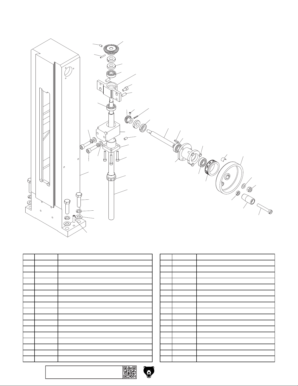
133
126
128
118 P0982118 LOCK NUT M8-1.25 136 P0982136 LOCK WASHER 8MM
115
116
Column
125
116
106
108
107
127
129
121
125
136
105
124
104
134
122
135
101
103
102
130
132
131
REF P ART # DESCRI PTIO N REF PART # DE S CRIPTION
101 P0982101 COL UMN 119 P0982119 KEY 4 X 4 X 16
102 P0982102 Z-AXIS LEADSCREW 120 P0982120 Z-AXIS HANDWHEEL SHAFT
103 P0982103 LI FT LO CK NUT (METRI C) 121 P0982121 ROLL PIN 3 X 16
104 P0982104 LI FT LO CK NUT (INCH) 122 P0982122 CAP SCREW M5-.8 X 20
105 P0982105 Z-AXIS LEADSCREW MOUNTING BRACKET 123 P0982123 HEX BOLT M5-.8 X 16
106 P0982106 LEADSCREW BEARING BLOCK 124 P0982124 SET SCREW M6-1 X 10
107 P0982107 TAPER PIN W/INT THREAD M6-1 X 16 125 P0982125 LOCK RING M12-1 X 6
108 P0982108 CAP SCREW M6-1 X 12 126 P0982126 BEVEL GEAR 30T
109 P0982109 BEARING SEAT 127 P0982127 BEVEL GEAR 15T
110 P0982110 HOLLOW HANDLE 128 P0982128 SET SCREW M5-.8 X 8
111 P0982111 HEX NUT M8-1. 25 THI N 129 P0982129 SET SCREW M5-.8 X 5
112 P0982112 HANDWHEEL 12 X M8-1.25 130 P0982130 HEX BOLT M10-1.5 X 40
113 P0982113 PLATE SPRING 131 P0982131 FLAT WASHER 1 0MM
114 P0982114 GRA DUATED DIAL 132 P0982132 LOCK WASHER 10MM
115 P0982115 ROLL PIN 3 X 20 133 P0982133 TAPER PIN W/I NT THREADS M6-1 X 24
116 P0982116 BALL BEARING 6001ZZ 134 P0982134 FLAT WA SHER 8MM
117 P0982117 HANDLE SCREW M8-1.25 X 55 135 P0982135 CAP SCREW M8-1.25 X 30
120
109
119
116
116
123
114
113
111
112
134
118
110
117
-66-
BUY PARTS ONLI NE AT GRIZZLY.COM!
Scan QR code to visit our Parts Store.
Model G0982/G0983 (Mfd. Since 01/24)

237
205
G0982 Only
222
223
210
236
242
231
230
225
228
229
224
210
240
226
239
232
247
239
219
248
Table
203
230
229
202
239
228
245
206
246
227
207
239
225
223
207
243
211
210
208
204
238
222
216
217
209
212
213
214
218
215
210
207
211
223
216
213
214
215
234
243
235
233
222
204
207
Model G0982/G0983 (Mfd. Since 01/24)
241
244
249
250
221
201
220
BUY PARTS ONLI NE AT GRIZZLY.COM!
Scan QR code to visit our Parts Store.
-67-

Table Parts List
225 P0982225 ADJUSTABLE HANDLE M6-1 X 16 250 P0982250 FLAT WASHER 8MM
REF PART # DE SCRIP TION REF P ART # DE S CRIPTIO N
201 P0982201 TABLE BASE 226 P0982226 X-AXIS LOCKING PIN
202 P0982202 SADDLE 227 P0982227 Y-AXIS LOCKING PIN
203 P0982203 TABLE 228 P0982228 CAP SCREW M4-.7 X 14
204 P0982204 BEARING SEAT 229 P0982229 CAP SCREW M5-.8 X 20
205 P0982205 TABLE END COVER (G0982) 230 P0982230 TAPER PIN 3 X 30
206 P0982206 X-AXIS GIB 231 P0982231 LEADSCREW SLEEVE (G0982)
207 P0982207 THRUST BEA RI NG 8101 232 P0982232 DRAIN PLUG M16-1.5 X 6
208 P0982208 X-AXIS LEADSCREW CLUTCH 233 P0982233 HANDWHEEL 10 X M8-1
209 P0982209 TAPER PIN 4 X 28 234 P0982234 LOCK NUT M8-1.25
210 P0982210 RIVET 2 X 4MM NAMEPLATE, STEEL 235 P0982235 FLAT WASHER 8MM
211 P0982211 DIAL I NDI CATOR 236 P0982236 BALL OILER 6MM PRESS-IN (G0982)
212 P0982212 HANDWHEEL 20 X M8-1 237 P0982237 TABLE COVER PLUG (G0982)
213 P0982213 HEX NUT M8-1. 25 THI N 238 P0982238 COMPRESSION SPRING 1 X 14.2 X 33
214 P0982214 HOLLOW HANDLE 239 P0982239 GIB SCREW M6-1 X 25
215 P0982215 SHOULDER SCREW M8-1 X 9.5, 13 X 5 240 P0982240 COMPRESSION SPRING 1 X 9.2 X 14
216 P0982216 PLATE SPRING 241 P0982241 KEY 4 X 4 X 16
217 P0982217 FLAT WASHER 12 MM 242 P0982242 X-AXIS SCALE
218 P0982218 CAP SCREW M4-.7 X 10 243 P0982243 GRADUATE D DI A L
219 P0982219 Y-AXIS GIB 244 P0982244 Y-AXIS LEADSCREW
220 P0982220 CAP SCREW M6-1 X 10 245 P0982245 Y-AXIS LEADSCREW NUT
221 P0982221 FENDER WAS HER 6MM 246 P0982246 X-AXIS LEADSCREW
222 P0982222 CAP SCREW M6-1 X 16 247 P0982247 X-AXIS LEADSCREW NUT
223 P0982223 TAPER PIN 4 X 20MM 248 P0982248 CAP SCREW M8-1.25 X 30
224 P0982224 X-AXIS SCALE INDICATOR 249 P0982249 LOCK WASHER 8MM
-68-
BUY PARTS ONLI NE AT GRIZZLY.COM!
Scan QR code to visit our Parts Store.
Model G0982/G0983 (Mfd. Since 01/24)

309
314 P0982314 PHLP HD SCR M4-.7 X 8
308
310
304
315
Chip Guard & Way Covers
311
306
313
314
318
316
327
312
317
305
315
301
303
302
326
320
322
319
302
324
327
321
322
323
322
325
307
REF PART # DE S CRIPTI ON REF PART # DESCRIP TION
301 P0982301 MA GNET MO UNT 315 P0982315 FL AT HD SCR M4 -. 7 X 10
302 P0982302 PHLP HD SCR M4-.7 X 10 316 P0982316 ROD LOCK COLLAR
303 P0982303 FL AT WAS HER 4MM 317 P0982317 CHIP G UARD ROD
304 P0982304 S AFETY SWI TCH MOUNT 318 P0982318 CAP SCREW M4-.7 X 12
305 P0982305 STRIKE PLATE 319 P0982319 WA Y COV ER SCREW BRACKET (FRONT)
306 P0982306 FL AT WAS HER 6MM 320 P0982320 WAY COVER SCREW BRACKET (REAR)
307 P0982307 CHIP GUARD EXTENSION 321 P0982321 WAY COVER MAGNET BRACKET
308 P0982308 CHI P GUARD 322 P0982322 PHLP HD SCR M5-.8 X 6
309 P0982309 K NURLED THUMB SCREW M5 -. 8 X 25 , D1 2 323 P0982323 Y-AXIS WAY COVER
310 P0982310 FL AT WAS HER 5MM 324 P0982324 Z-AXIS WAY COVER
311 P0982311 L OCK NUT M6 -1 325 P0982325 SPLASH GUARD (LARGE)
312 P0982312 CHI P GUARD MOUNTI NG BRACKET 326 P0982326 SPLASH GUARD (SMALL)
313 P0982313 SET SCREW M4-.7 X 6 327 P0982327 MAGNET 6MM
Model G0982/G0983 (Mfd. Since 01/24)
BUY PARTS ONLI NE AT GRIZZLY.COM!
Scan QR code to visit our Parts Store.
-69-

350
359 P0982359 DRAWBAR/QUILL LOCK LEVER 369 P0982369 WRENCH 17 X 19MM OPEN-ENDS
352
353
Stand & Accessories
351
359
357
358
360
354
355
356
363
365
352
353
366
361
367
362
364
369
368
REF PART # DE S CRIPTI ON REF PART # DE S CRIPTI ON
350 P0982350 CHI P TRAY 360 P0982360 SPI NDLE SPANNER WRENCH 5 0MM
351 P0982351 CAP SCREW M8-1.25 X 10 361 P0982361 OIL BOTTLE
352 P0982352 LOCK WASHER 8MM 362 P0982362 T-SLOT NUT M12-1.75
353 P0982353 FL AT WAS HER 8MM 363 P0982363 HEX WRENCH SET (4- PC)
354 P0982354 CABINET 364 P0982364 HE X WRENCH 8MM
355 P0982355 CABINET DOOR 365 P0982365 HEX NUT M8-1 . 25
356 P0982356 DOOR LOCK ASSEMBLY 366 P0982366 STUD-DE M8-1.25 X101, 36
357 P0982357 DRILL CHUCK KEY 5/16" STD 11T SD-9/16" 367 P0982367 WRENCH 8 X 10MM OPEN- ENDS
358 P0982358 DRILL CHUCK JT6 1/8"-5/8" 368 P0982368 WRENCH 14 X 17MM OPEN-ENDS
-70 -
BUY PARTS ONLI NE AT GRIZZLY.COM!
Scan QR code to visit our Parts Store.
Model G0982/G0983 (Mfd. Since 01/24)

Main Electrical Components
417
404
403
428
405
406
401
409
407
402
G0982 Only
419
412
410
408
444
435
445
415
411
412
446
413
410
414
418
416
423
420-2
420
420-1
431
432
422
432
434
441
447
433
429
442
G0983 Only
445
G0983 Only
448
450
449
425
426
444
435
443
G0983 Only
427
410
430
435
439
424
438
423
435
436
437
410
440
435
Model G0982/G0983 (Mfd. Since 01/24)
BUY PARTS ONLI NE AT GRIZZLY.COM!
Scan QR code to visit our Parts Store.
-71-

Main Electrical Components Parts List
425 P0982425 FLAT HD S CR M3-. 5 X 12
REF PART # DE S CRIP TI ON RE F PART # DES CRIPTIO N
401 P0982401 ON/ OFF BUTTON WENZHOU J 1 9-2 71B 426 P0982426 RECEPTACLE W/FUSE MALE IEC C14 PST-101
402 P0982402 REVERSE BUTTON WENZHOU J16-E-271B 427 P0982427 HE X NUT M3- . 5
403 P0982403 E-STOP BUTTON KEDU HY57B 428 P0982428 LIMIT SWITCH KEDU QKS7
404 P0982404 SPINDLE SPEED DIAL 429 P0982429 PHLP HD SCR M4-.7 X 30
405 P0982405 MI RRO R PANEL 430 P0982430 STRAIN RELIEF TYPE-3 M12-1.75
406 P0982406 CONTROL PANEL 431 P0982431 STANDOFF-HEX MF M3-.5 X 6, M3-.5 NYLON
407 P0982407 POTENTIOMETER B103 10K 432 P0982432 PHLP HD SCR M3-.5 X 6
408 P0982408 LED CI RCUIT BO ARD Z10 00- 7-A B-L ED 433 P0982433 CIRCUI T BOARD WG PCB 181 0 ZD-2
409 P0982409 TAP SCREW M2.9 X 6.5 434 P0982434 ELECTRICAL PANEL (UPPER)
410 P0982410 HEX NUT M4 -. 7 435 P0982435 PHLP HD SCR M4-.7 X 10
411 P0982411 MOUNTI NG PLATE 436 P0982436 CIRCUIT BOARD WGPCB FC750BJ-2/110V
412 P0982412 TAP SCREW M2.9 X 10 437 P0982437 PHLP HD SCR M5-.8 X 6
413 P0982413 CONTROL BOX 438 P0982438 LOCK WASHER 5MM
414 P0982414 PHLP HD SCR M3-.5 X 12 439 P0982439 GROUND TE RMI NA L BAR
415 P0982415 USB P ORT W/CORD 47" 440 P0982440 DUST SCREE N
416 P0982416 HEX BOLT M4-.7 X 16 441 P0982441 ELECTRICAL PANEL (LOWER)
417 P0982417 STRAIN RELIEF TYPE-5 M32-1.5 442 P0983442 3-AXIS DIGITAL DISPLAY SIEG MG10V (G0983)
418 P0982418 STRAIN RELIEF TYPE-5 M40-1.5 443 P0983443 STRAIN RELIEF MOUNTING PLATE DOUBLE (G0983)
419 P0982419 HOLE PLUG 28MM (G0982) 444 P0983444 STRAIN RELIEF TYPE-1 1/2" (G0983)
420 P0982420 MOTOR 1HP 110VDC 445 P0983445 STRAIN RELIEF TYPE-5 M30-1.5 (G0983)
420-1 P0982420-1 CARBON BRUSH (2-PC SET) 446 P0983446 STRAIN RELIEF MOUNTING PLATE SINGLE (G0983)
420-2 P0982420-2 BRUS H CAP 447 P0982447 FLAT HD S CR M3-. 5 X 6
422 P0982422 SPEED SENSOR RSD-1A(M8-28) 448 P0982448 LIMI T SWI TCH CORD
423 P0982423 PHLP HD SCR M5-.8 X 8 449 P0982449 FUSE 15A 250V
424 P0982424 COLUMN CO VER 450 P0982450 POWER CORD 16G 3W 72" 5-15P
-72-
BUY PARTS ONLI NE AT GRIZZLY.COM!
Scan QR code to visit our Parts Store.
Model G0982/G0983 (Mfd. Since 01/24)

G0983 Power Feed & 3-Axis Sensors
503-2
503-1
503
518
505
506
508
519
601
508
810
602
809
808
603
509
510
802
803
811
812
804
604
614
511
613
801
807
806
612
805
605
611
606
607
610
806
809
810
608
810
703
809
805
701
702
706
701
707
704
711
713
714
705
712
708
715
709
710
507
504
502
501
517
501
515
516
Model G0982/G0983 (Mfd. Since 01/24)
512
514
BUY PARTS ONLI NE AT GRIZZLY.COM!
Scan QR code to visit our Parts Store.
-73 -

G0983 Power Feed & 3-Axis Sensors Parts List
611 P0983611 LEADSCREW SELECTOR KNOB M6-1 812 P0983812 Z-AXIS SENSOR BRACKET
REF PART # DESCRIP TION REF P ART # DESCRI PTIO N
501 P0983501 TAP SCREW M2.9 X 10 612 P0983612 CAP SCREW M3-.5 X 8
502 P0983502 CONTROL BOX COVER (SIDE) 613 P0983613 LEADSCREW SELECTOR FLANGE
503 P0983503 MOTOR 96W 24VDC 614 P0983614 E CCENTRI C SHAFT
503-1 P0983503-1 CARBON BRUSH (2-PC SET) 701 P0983701 HEX NUT M5-. 8
503-2 P0983503-2 BRUSH CAP 702 P0983702 X-AXIS LIMIT BLOCK
504 P0983504 TAP SCREW M2.9 X 6.5 703 P0983703 T-BOLT M5-.8 X 30
505 P0983505 KEY 3 X 3 X 12 704 P0983704 SWI TCH BOX MOUNTI NG PLATE
506 P0983506 SOCKET DC-005 705 P0983705 CAP SCREW M4-.7 X 10
507 P0983507 CONTROL BOX 706 P0983706 KNURLED THUMB SCREW M5-.8 X 25, D12
508 P0983508 CAP SCREW M4-.7 X 20 707 P0983707 COMPRESSION SPRING 0.5 X 5.2 X 34
509 P0983509 3-PI N CONNECTOR SOCKET ZHOUSHI GX12-3P 708 P0983708 SWI TCH BOX
510 P0983510 POWER I NDICATO R HL-1 709 P0983709 X-AXI S LIMIT SWITCH CORD 20G 3W 39"
511 P0983511 SPEED DIAL 710 P0983710 3- PI N CONNECTOR PLUG M12-3
512 P0983512 FA ULT I NDI CA TOR H-7 711 P0983711 TAP SCREW M4 X 10
514 P0983514 POTENTIOMETER H24-2 4.7K 712 P0983712 X-AXIS LIMIT SWITCH OMRON SS-5GL
515 P0983515 DI RECTI O N SWI TCH KEDU HY 29K 713 P0983713 SWI TCH PRESS BUTTON
516 P0983516 CONTROL BOX COVER (BOTTOM) 714 P0983714 CAP SCREW M4-.7 X 8
517 P0983517 CI RCUIT BO ARD ZHENY I X MT-24 03 715 P0983715 STRAIN RELIEF TYPE-1 1/2"
518 P0983518 POWER ADAPTER W/CORD 16G 2W 48" DCP 801 P0983801 SPACER 3.2 X 6 X 4MM
519 P0983519 ADAPTER POWER CORD 18G 3W 59" 5-15P 802 P0983802 Z-AXIS MAGNETIC SCALE
601 P0983601 CLUTCH ASSEMBLY 803 P0983803 PHLP HD SCR M3-.5 X 10
602 P0983602 CAP SCREW M6-1 X 20 804 P0983804 Y-AXIS MAGNETIC SCALE
603 P0983603 ECCENTRI C SHAFT B OX 805 P0983805 X/Y AXIS SENSOR BRACKET
604 P0983604 SHAFT SLEEVE 806 P0983806 CAP SCREW M4-.7 X 10
605 P0983605 ROLL PIN 3 X 8 807 P0983807 X-AXIS MAGNETIC SCALE
606 P0983606 SET SCREW M6-1 X 8 808 P0983808 CAP SCREW M4-.7 X 25
607 P0983607 STEEL BALL 4MM 809 P0983809 MAGNETIC SENSOR SIEG MG10V
608 P0983608 SET SCREW M6-1 X 8 810 P0983810 PHLP HD SCR M3-.5 X 12
610 P0983610 COMPRESSION SPRING 0.7 X 4 X 25 811 P0983811 SPACER BLOCK
-74 -
BUY PARTS ONLI NE AT GRIZZLY.COM!
Scan QR code to visit our Parts Store.
Model G0982/G0983 (Mfd. Since 01/24)

903
G0982 Labels & Cosmetics
905 P0982905 ELECTRICITY LABEL
WARNING!
To reduce risk of death
or serious injury, read
manual BEFORE using
machine.
To get a new manual,
call (800) 523-4777 or
go to www.grizzly.com.
WARNING!
EYE/FACE INJURY
HAZARD!
Always wear
ANSI-approved safety
glasses and face shield
when using this
machine.
901
Disconnect power
before adjustments,
maintenance, or
service.
Tie back long hair, roll up
long sleeves, and remove
loose clothing, jewelry, or
gloves to prevent getting
caught in moving parts.
WARNING!
INJURY/SHOCK
HAZARD!
WARNING!
ENTANGLEMENT
HAZARD!
909
908
902
NOTICE
FOLLOW SPINDLE
BREAK-IN PROCEDURES
BEFORE OPERATING
THIS MACHINE!
Failure to follow spindle
break-in procedures in your
manual will reduce machine
life and may void warranty.
Specifications
Motor: 1 HP, 110V, 1-Ph, 60 Hz
Full-Load Current Rating: 11A
Max. Distance Spindle to Column: 6-1/2"
Max. Distance Spindle to Table: 12-3/8"
Spindle Travel: 2-3/4"
Spindle Taper: R-8
Spindle Speeds: 100–2000 RPM
Longitudinal Table Travel: 19-3/4"
Cross Table Travel: 6-1/16"
Vertical Head Travel: 9-1/4"
End Milling Capacity: 5/8"
Face Milling Capacity: 2"
Weight: 324 lbs.
Date
S/N
Mfd. for Grizzly in China
904
MODEL G0982
6" X 27" MILL/DRILL
w/MIRROR DISPLAY
To reduce the risk of serious personal injury while using this machine:
1. Read and understand owner’s manual before operating.
2. Always wear approved safety glasses AND a face shield.
3. Only plug power cord into a grounded outlet.
4. Disconnect power before setting up, adjusting, or servicing.
5. Avoid getting entangled in moving parts—tie back long hair, roll up
6. Properly set up machine before starting.
7. Always remove chuck keys and adjustment tools before starting.
8. Keep all guards and covers in place during operation.
9. Only use clamps or a vise to secure workpiece for operations.
10. Avoid positioning hands where they could slip into rotating bits or
11. Only use a brush or vacuum to remove metal chips.
12. Never attempt to slow or stop spindle with hands or tools.
13. Always use proper feeds and speeds for operation and workpiece.
14. Never leave machine running unattended.
15. DO NOT expose to rain or use in wet locations.
16. Prevent unauthorized use by children or untrained users.
WARNING!
long sleeves, and DO NOT wear loose clothing, gloves, or jewelry.
tooling if workpiece unexpectedly shifts or you get distracted.
905
905
907
906
REF PART # DESCRIP TION REF PART # DESCRI PTION
901 P0982901 COMBO WARNING LABEL 906 P0982906 GRIZZLY.COM LABEL
902 P0982902 NOTI CE HANG TAG 907 P0982907 TOUCH-UP PAINT, GRIZZLY GREEN
903 P0982903 MACHINE ID LABEL 908 P0982908 MODEL NUMBER LABEL
904 P0982904 TOUCH-UP PAINT, GRIZZLY BLACK 909 P0982909 GRIZZLY NAMEPLATE MINI
Safety labels help reduce the risk of serious injury caused by machine hazards. If any label comes
off or becomes unreadable, the owner of this machine MUST replace it in the original location
before resuming operations. For replacements, contact (800) 523-4777 or www.grizzly.com.
Model G0982/G0983 (Mfd. Since 01/24)
BUY PARTS ONLI NE AT GRIZZLY.COM!
Scan QR code to visit our Parts Store.
-75 -

901
G0983 Labels & Cosmetics
905 P0983905 ELECTRICITY LABEL 910 P0983910 READ MANUAL LABEL
909
WARNING!
INJURY/SHOCK
HAZARD!
Disconnect power
before adjustments,
maintenance, or
service.
910
WARNING!
To reduce risk of death
or serious injury, read
manual BEFORE using
machine.
To get a new manual, call
(800) 523-4777 or go to
www.grizzly.com.
902
NOTICE
FOLLOW SPINDLE
BREAK-IN PROCEDURES
BEFORE OPERATING
THIS MACHINE!
Failure to follow spindle
break-in procedures in your
manual will reduce machine
life and may void warranty.
WARNING!
ENTANGLEMENT
HAZARD!
Tie back long hair, roll up
long sleeves, and remove
loose clothing, jewelry, or
gloves to prevent getting
caught in moving parts.
WARNING!
EYE/FACE INJURY
HAZARD!
Always wear
ANSI-approved safety
glasses and face shield
when using this
machine.
Specifications
Motor: 1 HP, 110V, 1-Ph, 60 Hz
Full-Load Current Rating: 11A
Max. Distance Spindle to Column: 6-1/2"
Max. Distance Spindle to Table: 12-3/8"
Spindle Travel: 2-3/4"
Spindle Taper: R-8
Spindle Speeds: 100–2000 RPM
Longitudinal Table Travel: 19-3/4"
Cross Table Travel: 6-1/2"
Vertical Head Travel: 9-1/4"
End Milling Capacity: 5/8"
Face Milling Capacity: 2"
Weight: 337 lbs.
Mfd. for Grizzly in China
904
903
MODEL G0983 6" X 27"
MILL/DRILL w/MIRROR DISPLAY,
3-AXIS DRO & POWER FEED
To reduce the risk of serious personal injury while using this machine:
1. Read and understand owner’s manual before operating.
2. Always wear approved safety glasses AND a face shield.
3. Only plug power cord into a grounded outlet.
4. Disconnect power before setting up, adjusting, or servicing.
5. Avoid getting entangled in moving parts—tie back long hair, roll up
6. Properly set up machine before starting.
7. Always remove chuck keys and adjustment tools before starting.
8. Keep all guards and covers in place during operation.
9. Only use clamps or a vise to secure workpiece for operations.
10. Avoid positioning hands where they could slip into rotating bits or
Date
S/N
11. Only use a brush or vacuum to remove metal chips.
12. Never attempt to slow or stop spindle with hands or tools.
13. Always use proper feeds and speeds for operation and workpiece.
14. Never leave machine running unattended.
15. DO NOT expose to rain or use in wet locations.
16. Prevent unauthorized use by children or untrained users.
WARNING!
long sleeves, and DO NOT wear loose clothing, gloves, or jewelry.
tooling if workpiece unexpectedly shifts or you get distracted.
905
905
908
907
906
REF PART # DE SCRIP TI ON REF PART # DES CRIPTION
901 P0983901 COMBO WARNING LABEL 906 P0983906 GRIZZLY.COM LABEL
902 P0983902 NOTI CE HANG TA G 907 P0983907 TOUCH-UP PAINT, GRIZZLY GREEN
903 P0983903 MACHINE ID LABEL 908 P0983908 MODEL NUMBER LABEL
904 P0983904 TOUCH-UP PAINT, GRIZZLY BLACK 909 P0983909 GRIZZLY NAMEPLATE MINI
Safety labels help reduce the risk of serious injury caused by machine hazards. If any label comes
off or becomes unreadable, the owner of this machine MUST replace it in the original location
before resuming operations. For replacements, contact (800) 523-4777 or www.grizzly.com.
-76 -
BUY PARTS ONLI NE AT GRIZZLY.COM!
Scan QR code to visit our Parts Store.
Model G0982/G0983 (Mfd. Since 01/24)

WARRANTY & RETURNS
Grizzly Industrial, Inc. warrants every product it sells for a period of 1 year to the original purchaser from
the date of purchase. This warranty does not apply to defects due directly or indirectly to misuse, abuse,
negligence, accidents, repairs or alterations or lack of maintenance. This is Grizzly’s sole written warranty
and any and all warranties that may be implied by law, including any merchantability or fitness, for any particular purpose, are hereby limited to the duration of this written warranty. We do not warrant or represent
that the merchandise complies with the provisions of any law or acts unless the manufacturer so warrants.
In no event shall Grizzly’s liability under this warranty exceed the purchase price paid for the product and
any legal actions brought against Grizzly shall be tried in the State of Washington, County of Whatcom.
We shall in no event be liable for death, injuries to persons or property or for incidental, contingent, special,
or consequential damages arising from the use of our products.
The manufacturers reserve the right to change specifications at any time because they constantly strive to
achieve better quality equipment. We make every effort to ensure that our products meet high quality and
durability standards and we hope you never need to use this warranty.
In the event you need to use this warranty, contact us by mail or phone and give us all the details. We will
then issue you a “Return Number,’’ which must be clearly posted on the outside as well as the inside of
the carton. We will not accept any item back without this number. Proof of purchase must accompany the
merchandise.
Please feel free to write or call us if you have any questions about the machine or the manual.
Thank you again for your business and continued support. We hope to serve you again soon.
For further information about the
scan the QR
code below
to be automatically directed to our warranty page.
warranty, visit https://www.grizzly.com/forms/warranty or
WARRANTY

 Loading...