


READ THIS FIRST
Model G0960
***IMPORTANT UPDATE***
For Machines Mfd. Since 09/22
and Owner's Manual Printed 10/22
For questions or help with this product contact Tech Support at (570) 546-9663 or techsupport@grizzly.com
The following changes were recently made since the owner's manual was printed:
• Instructions for Adjusting Blade Support Bearings have been updated.
Aside from this information, all other content in the owner's manual applies and MUST be read and understood for your own safety. IMPORTANT: Keep this update with the owner's manual for future reference.
For questions or help, contact our Tech Support at (570) 546-9663 or techsupport@grizzly.com.
COPYRIGHT © MAY, 2024 BY GRIZZLY INDUSTRIAL, INC.
WARNING: NO PORTION OF THIS MANUAL MAY BE REPRODUCED IN ANY SHAPE
OR FORM WITHOUT THE WRITTEN APPROVAL OF GRIZZLY INDUSTRIAL, INC.
#CS23218 PRINTED IN TAIWAN

(Replaces Page 40 in Manual)
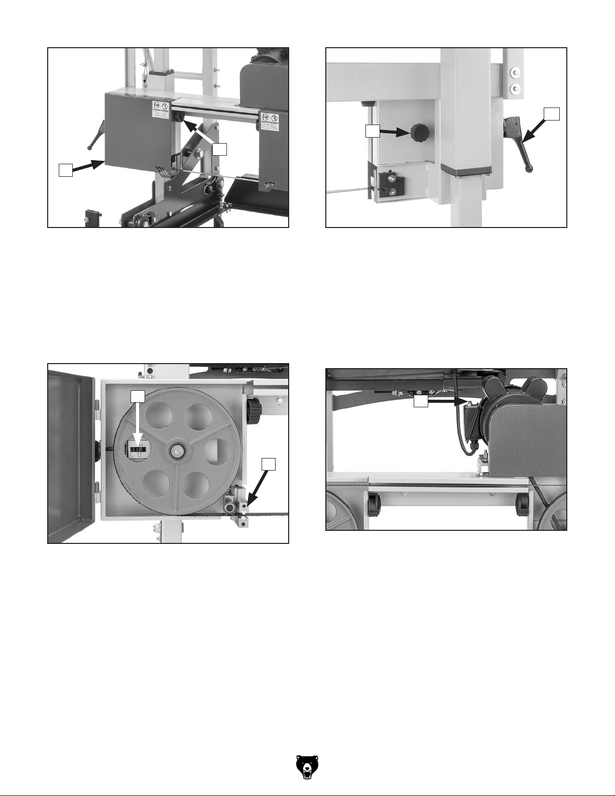
To adjust blade guide assemblies:
1. DISCONNECT MACHINE FROM POWER!
Loosen blade guide assembly adjustment
2.
screw (see Figure 72) so you can slide blade
guide assembly forward and backward.
Blade Guide
Assembly
Adjustment Screw
Blade
Guides
Blade Guide
Assembly
Figure 72. Location of blade guide assembly
and adjustment screw.
3.
Adjust blade guide assembly until there is
about 0.016" between front of blade guide
and blade gullets (see Figure 73).
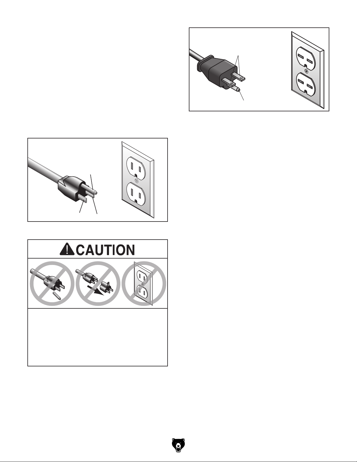
Adjusting Blade Support Bearings
When properly adjusted, there is about 0.016"
between the blade support bearings and the
blade.
Items Needed Qty
Feeler Gauge 0.4mm (0.016") ........................... 1
Hex Wrench 3mm
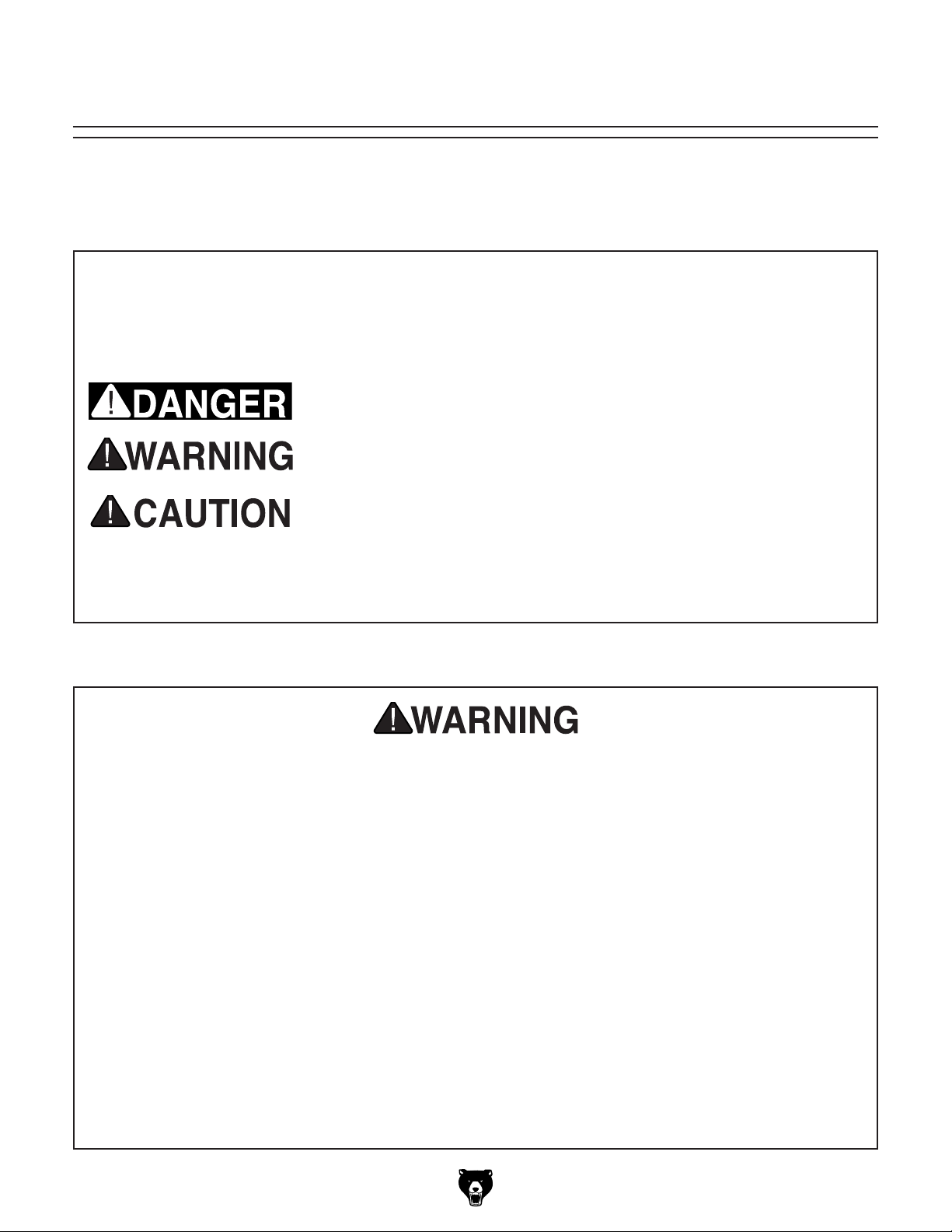
To adjust blade support bearings:
1. DISCONNECT MACHINE FROM POWER!
Loosen support bearing adjustment screw on
2.
blade guide (see Figure 71) so you can slide
bearing forward and backward.
Support
Bearing
.............................................. 1
Support Bearing
Adjustment Screw
1
/64" or 0.016"
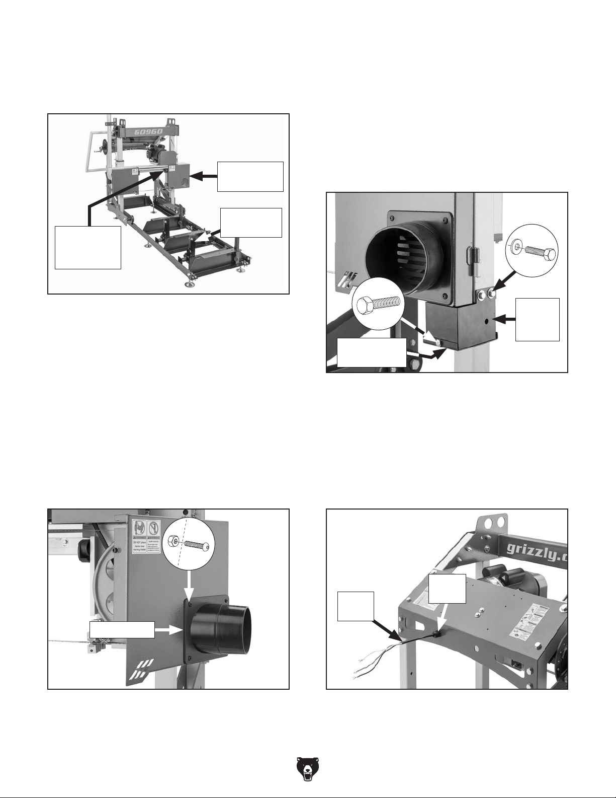
Blade
Blade
Guide
Gullets
Figure 73. Blade guide positioned 0.016" behind
blade gullets.
4.
Tighten blade guide assembly adjustment
screw to secure.
Repeat Steps 2–4 on second blade guide
5.
assembly.
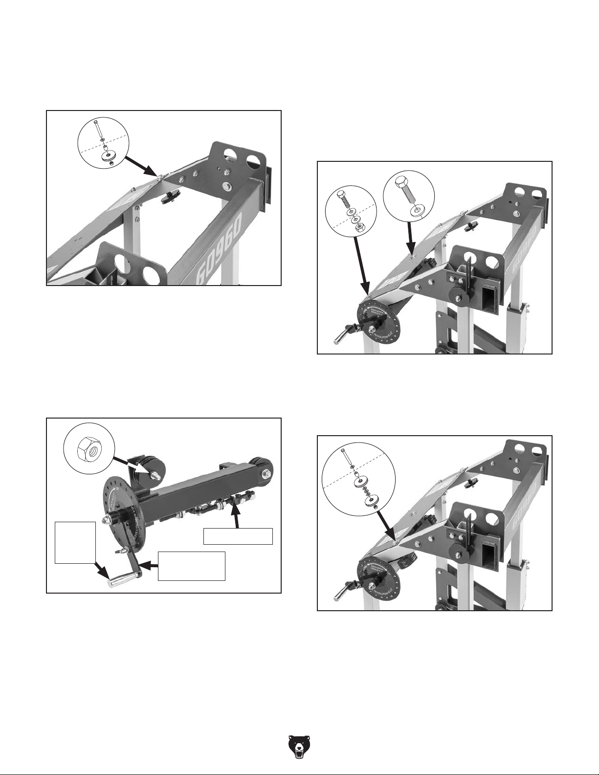
Figure 74. Location of support bearing and
adjustment screw.
3. Adjust support bearing until there is about
0.016" between front of support bearing and
back of blade (see Figure 75).
Back of Blade
1
/64" or 0.016"
Support Bearing
Figure 75. Support bearing positioned 0.016"
behind back of blade.
-2-
G0960 Update (Mfd. Since 09/22)

MODEL G0960
MINI SAWMILL PRO
OWNER'S MANUAL
(For models manufactured since 09/22)
COPYRIGHT © OCTOBER, 2022 BY GRIZZLY INDUSTRIAL, INC.
WARNING : NO PORTION OF THIS MANUAL MAY BE REPRODUCED IN ANY SHAPE
OR FORM WITHOUT THE WRITTEN APPROVAL OF GRIZZLY INDUSTRIAL, INC.
#CSLW22408 PRINTED IN TAIWA N
***Keep for Future Reference***
V1.1 0. 2 2

This manual provides critical safety instructions on the proper setup,
operation, maintenance, and service of this machine/tool. Save this
document, refer to it often, and use it to instruct other operators.
Failure to read, understand and follow the instructions in this manual
may result in fire or serious personal injury—including amputation,
electrocution, or death.
The owner of this machine/tool is solely responsible for its safe use.
This responsibility includes but is not limited to proper installation in
a safe environment, personnel training and usage authorization,
proper inspection and maintenance, manual availability and comprehension, application of safety devices, cutting/sanding/grinding tool
integrity, and the usage of personal protective equipment.
The manufacturer will not be held liable for injury or property damage
from negligence, improper training, machine modifications or misuse.
Some dust created by power sanding, sawing, grinding, drilling, and
other construction activities contains chemicals known to the State
of California to cause cancer, birth defects or other reproductive
harm. Some examples of these chemicals are:
• Lead from lead-based paints.
• Crystalline silica from bricks, cement and other masonry products.
• Arsenic and chromium from chemically-treated lumber.
Your risk from these exposures varies, depending on how often you
do this type of work. To reduce your exposure to these chemicals:
Work in a well ventilated area, and work with approved safety equipment, such as those dust masks that are specially designed to filter
out microscopic particles.

Table of Contents
INTRODUCTION ............................................... 2
Contact Info.................................................... 2
Manual Accuracy
Identification
Controls & Components
Glossary Of Terms
Machine Data Sheet
SECTION 1: SAFETY
Safety Instructions for Machinery
Additional Safety for Sawmills
SECTION 2: POWER SUPPLY
SECTION 3: SETUP
Needed for Setup
Unpacking
Inventory
Hardware Recognition Chart
Cleanup
Site Considerations
Assembly
Converting Voltage to 220V
Dust Collection
Test Run
SECTION 4: OPERATIONS
Operation Overview
Workpiece Inspection................................... 35
Changing Blade
Tensioning Blade
Adjusting Blade Tracking
Adjusting Blade Guides
Types of Lumber
Drying Lumber
Cant Sawing................................................. 43
Live Sawing.................................................. 44
Edging
Quarter Sawing
.................................................... 14
...................................................... 15
........................................................ 18
..................................................... 20
...................................................... 33
.......................................................... 45
........................................... 2
................................................... 3
................................. 4
......................................... 6
...................................... 7
....................................... 9
.................. 9
..................... 11
...................... 12
....................................... 14
......................................... 14
....................... 17
...................................... 19
......................... 31
............................................. 32
........................... 34
..................................... 34
........................................... 35
......................................... 36
............................. 38
............................... 39
.......................................... 41
............................................. 42
............................................ 46
SECTION 5: ACCESSORIES ......................... 48
SECTION 6: MAINTENANCE
Schedule
Cleaning
Lubrication
SECTION 7: SERVICE
Troubleshooting
Tensioning/Replacing V-Belt........................ 55
Calibrating Blade Height Scale
Adjusting Wheel Alignment
SECTION 8: WIRING
Wiring Safety Instructions
Wiring Diagram
Electrical Component Photos
SECTION 9: PARTS
Track
Saw Head
Carriage
Carriage Leg Roller & Post Sleeve
Lift Assembly................................................ 69
Blade Guides
Labels & Cosmetics (Front)
Labels & Cosmetics (Rear)
WARRANTY & RETURNS
...................................................... 51
....................................................... 51
................................................... 51
................................... 52
........................................... 52
...................................... 61
............................................ 62
....................................... 64
............................................................ 64
.................................................... 65
....................................................... 67
............................................... 70
......................... 51
.................... 57
.......................... 58
............................ 61
...................... 63
.............. 68
......................... 71
.......................... 72
............................. 73

We stand behind our machines! If you have questions or need help, contact us with the information
below. Before contacting, make sure you get the
serial number
from the
machine ID label. This will help us help you faster.
We want your feedback on this manual. What did
you like about it? Where could it be improved?
Please take a few minutes to give us feedback.
Email: manuals@grizzly.com
We are proud to provide a high-quality owner’s
manual with your new machine!
We
instructions, specifications, drawings, and photographs
in this manual. Sometimes we make mistakes, but
our policy of continuous improvement also means
that
you receive is
slightly different than shown in the manual
If you find this to be the case, and the difference
between the manual and machine leaves you
confused or unsure about something
check our
website for an updated version. W
current
manuals and
on our web-
site at
Alternatively, you can call our Technical Support
for help. Before calling, make sure you write
down the
serial number
from the machine ID label (see below). This
information is required for us to provide proper
tech support, and it helps us determine if updated
documentation is available for your machine.
INTRODUCTION
Contact Info
and manufacture date
Grizzly Technical Support
1815 W. Battlefield
Springfield, MO 65807
Phone: (570) 546-9663
Email: techsupport@grizzly.com
Grizzly Documentation Manager
P.O. Box 2069
Bellingham, WA 98227-2069
Manual Accuracy
made every effort to be exact with the
sometimes the machine
.
,
e post
manual updates for free
www.grizzly.com.
manufacture date and
Manufacture Date
Serial Number
-2-
Model G0960 (Mfd. Since 09/22)

Identification
Become familiar with the names and locations of the controls and features shown below to better understand
the instructions in this manual.
ON/OFF Switch
w/Disabling Key
Blade Height
Scale
Push
Handle
Blade Height
Controls
Blade Tracking
Knob
Log Bunk
Adjustable
Foot
Log
Clamp
Carriage
Blade Tension
Lever
Blade Cover
Dust
Port
Track
Log
Support
Model G0960 (Mfd. Since 09/22)
-3-

Controls &
To reduce your risk of
serious injury, read this
entire manual BEFORE
Carriage
Components
using machine.
Refer to the following figures and descriptions to
become familiar with the basic controls and components of this machine. Understanding these
items and how they work will help you understand
the rest of the manual and minimize your risk of
injury when operating this machine.
Track
A
F
G
H
Figure 2. Blade height controls.
F. Blade Height Handwheel: Provides notch-
es to position blade height lever at 0.01"
increments. One full revolution of handwheel
moves blade approximately 0.2".
G. Blade Height Index Plunger: Uses cam-
action to seat plunger in blade height
handwheel notches to secure height setting.
Turn lever 180° to keep plunger from seating.
B
E
Figure 1. Track components.
A. Log Clamp (1 of 2): Secures log against log
support.
B. Rail: Supports carriage.
C. Adjustable Foot (1 of 6): Keeps track level
and stable.
D. Log Support (1 of 2): Secures and levels log
to ensure flat cuts.
IMPORTANT: Log supports and log clamps
must be adjusted/angled to stay below saw
blade height during operation.
D
C
H. Blade Height Handle: Raises/lowers saw
blade.
I
J
Figure 3. Operator controls.
I. ON/OFF Switch w/Disabling Key: Turns
machine ON when pulled out; turns machine
OFF when pressed in. When key is removed,
button is disabled and machine cannot start.
E. Log Bunk (1 of 4): Supports log.
-4-
J. Push Handle: Moves carriage along track.
Model G0960 (Mfd. Since 09/22)
P
O
K
L
Figure 4. Blade removal components.
K. Blade Cover Lock Knob (1 of 2): Turn knob
clockwise to open blade cover; turn knob
counterclockwise to secure blade cover.
L. Blade Cover (1 of 2): Protects blade and
wheels from elements, and guards operator
from entanglement and injury.
M
N
Figure 6. Blade tracking and tension controls.
O. Blade Tracking Knob: Adjusts blade
tracking on wheels.
P. Blade Tension Lever: Turn lever clockwise
to tension blade; turn lever counterclockwise
to release tension; lift lever to disengage.
Circuit Breaker
Q
Figure 5. Inside blade cover components.
M. Blade Tension Scale: Displays recommend-
ed blade tension according to blade width
and current tension setting.
N. Blade Guide (1 of 2): Supports blade.
Model G0960 (Mfd. Since 09/22)
Figure 7. Location of circuit breaker.
Q. Circuit Breaker Reset Button: Allows
machine to be restarted after thermal overload protection has tripped. To reset, push
ON/OFF switch in, wait a few minutes for
machine to cool, then press reset button. If
button does not stay depressed, allow motor
to cool longer, then try again.
-5-

Glossary Of Terms
The following is a list of common definitions, terms and phrases used throughout this manual as they relate
to this sawmill and milling in general. Become familiar with these terms for assembling, adjusting or operating this machine. Your safety is VERY important to us at Grizzly!
Board Foot: Unit of measurement for volume
of lumber cut from a log. Used to measure
productivity and cost. A board foot is typically
measured as a piece of wood 1' x 1' x 1", or 144
cubic inches.
Burl: A tough outgrowth on a log with deformed
grains that make elaborate patterns. Burls are
difficult to cut, but often have unique patterns
desirable to woodworkers.
Cant: Partially cut log with one to four flat sides.
A cant might be cut on a sawmill and moved
to another machine, finished on the sawmill, or
sold as-is.
Carriage: Structure that supports the motor and
saw blade and moves along the track.
Flatsawn: Lumber sawn nearly parallel to the
wood grain. Most efficient lumber to mill, but
most susceptible to warping and cupping. Also
called plainsawn lumber.
Flitch: Piece of wood with two flat surfaces and
one or two natural edges. Flitches can be
edged to produce finished lumber.
Grade Sawing: Process of rotating log or cant
multiple times throughout milling in order to
produce lumber of the highest possible grade.
Parallel: Being an equal distance apart at every
point along two given lines or planes; i.e., the
log bunks are parallel to the face of the saw
blade.
Perpendicular: Lines or planes that intersect and
form right angles; i.e., the blade is perpendicular to the log supports.
Pith: The central rings in a log or tree. The pith
is the oldest wood, created when the tree was
young. It is prone to cracking as wood dries and
shrinks.
Plainsawn: See "Flatsawn".
Quartersawn: Lumber sawn so the grain is
perfectly perpendicular to the flat surface of
the board. Quartersawn lumber is resistent to
warping and cupping, but is time consuming
and produces the most waste wood.
Riftsawn: Lumber sawn so that the grain is close
to perpendicular to the flat surface of the board.
Riftsawn lumber is resistant to warping and
cupping, but is time consuming to mill.
Slab: Piece of wood with one flat surface and the
rest is natural wood. As a by product of milling
lumber, slabs are often sectioned and used as
firewood.
Kerf: The resulting cut or gap in the workpiece
after the saw blade passes through during a
cutting operation.
Live Sawing: Process of cutting parallel through
log or cant from top to bottom. Most efficient
method of milling that produces flatsawn, quartersawn, and riftsawn lumber.
-6-
Sticker: Pieces of narrow wood (approximately
1"x1") used to separate lumber that is stacked
for air drying. Usually made of light wood that
will not stain the drying lumber.
Stickering: Process of stacking wood using stickers.
Waney: Edge of a board that is tapered or unfinished.
Model G0960 (Mfd. Since 09/22)

Machine Data Sheet
Customer Service #: (570) 546-9663 · To Order Call: (800) 523-4777 · Fax #: (800) 438-5901
MODEL G0960
MINI SAWMILL PRO
Product Dimensions:
Weight ..............................................................................................................................................................430 lbs.
Width (side-to-side) x Depth (front-to-back) x Height ................................................................... 44-1/2 x 79 x 64 in.
Footprint (Length x Width) .................................................................................................................... 74 x 24-1/2 in.
Shipping Dimensions:
Type ...................................................................................................................................................Wood Slat Crate
Content ............................................................................................................................................................ Machine
Weight ..............................................................................................................................................................585 lbs.
Length x Width x Height ...................................................................................................................... 45 x 34 x 32 in.
Must Ship Upright ....................................................................................................................................................No
Electrical:
Power Requirement ............................................................................................ 110V or 220V, Single-Phase, 60 Hz
Prewired Voltage .................................................................................................................................................. 110V
Full-Load Current Rating ...................................................................................................... 14A at 110V, 7A at 220V
Minimum Circuit Size ......................................................................................................... 20A at 110V, 15A at 220V
Connection Type .......................................................................................................................................Cord & Plug
Power Cord Included ............................................................................................................................................. Yes
Power Cord Length ............................................................................................................................................. 70 in.
Power Cord Gauge .........................................................................................................................................14 AWG
Plug Included ......................................................................................................................................................... Yes
Included Plug Type ................................................................................................................................ 5-15 for 110V
Recommended Plug Type ..................................................................................................................... 6-15 for 220V
Switch Type ........................................................................ Push Button w/Large Shut-Off Paddle & Removable Key
Motors:
Main
Horsepower ................................................................................................................................................ 2 HP
Phase ............................................................................................................................................Single-Phase
Amps .......................................................................................................................................................14A/7A
Speed ................................................................................................................................................ 1720 RPM
Type .................................................................................................................TEFC Capacitor-Start Induction
Power Transfer ............................................................................................................................................. Belt
Bearings .....................................................................................................Shielded & Permanently Lubricated
Centrifugal Switch/Contacts Type .......................................................................................................... Internal
Model G0960 (Mfd. Since 09/22)
-7-

Main Specifications:
Cutting Capacity
Max. Log Length (with included track sections) ................................................................................ 43-5/16 in.
Min. Log Length ........................................................................................................................................ 20 in.
Max. Log Diameter .................................................................................................................................... 13 in.
Min. Log Diameter ....................................................................................................................................... 4 in.
Max. Width of Cut ..................................................................................................................................... 13 in.
Max. Depth of Cut ................................................................................................................................. 6-1/2 in.
Min. Depth of Cut ................................................................................................................................. 0.075 in.
Max. Cutting Height ............................................................................................................................. 14-1/2 in.
Min. Height Above Bed .......................................................................................................................... 9/16 in.
Track Length ....................................................................................................................................... 78-1/2 in.
Track Width ..................................................................................................................................... 23-13/16 in.
Track Height ............................................................................................................................ 7-7/8 x 10-5/8 in.
Blade Information
Blade Speed .......................................................................................................................................2900 FPM
Blade Length ............................................................................................................................84 - 84-13/16 in.
Blade Width ...................................................................................................................................... 1/4 - 3/4 in.
Blade Thickness ....................................................................................................................... 0.025 - 0.030 in.
Blade Guides ............................................................................................................................ Ceramic Guides
Operation
Feed System ...........................................................................................................................................Manual
Lift System ..............................................................................................................................................Manual
Log Supports .......................................................................................................... 2 Supports & 2 Log Clamps
Construction
Track .......................................................................................................................................................... Steel
Frame ......................................................................................................................................................... Steel
Body ........................................................................................................................................................... Steel
Wheels .................................................................................................................................................Cast Iron
Paint Type/Finish ...................................................................................................................... Powder Coated
Additional Information:
Wheel Size .......................................................................................................................................................... 10 in.
Track Extensions ........................................................................................................................................... 39-3/8 in.
Track Leveling ..................................................................................................................................... Adjustable Feet
Number of Dust Ports ................................................................................................................................................ 1
Dust Port Size ....................................................................................................................................................... 4 in.
Other Specifications:
Country of Origin ...............................................................................................................................................Taiwan
Warranty .............................................................................................................................................................1 Year
Approximate Assembly & Setup Time ................................................................................................................5 Hrs.
Serial Number Location ...................................................................................................................................ID Label
Features:
13" Maximum Log Diameter and Width of Cut
Ceramic Blade Guides
Manual Lift System Raises 0.2" per Revolution
Low-to-the-Ground Bed
Two Adjustable Log Supports and Two Log Clamps
Included 84-7/16" x 3/4" x 0.025" 3 TPI Blade
-8-
Model G0960 (Mfd. Since 09/22)
SECTION 1: SAFETY
For Your Own Safety, Read Instruction
Manual Before Operating This Machine
The purpose of safety symbols is to attract your attention to possible hazardous conditions.
This manual uses a series of symbols and signal words intended to convey the level of importance of the safety messages. The progression of symbols is described below. Remember that
safety messages by themselves do not eliminate danger and are not a substitute for proper
accident prevention measures. Always use common sense and good judgment.
Indicates an imminently hazardous situation which, if not avoided,
WILL result in death or serious injury.
Indicates a potentially hazardous situation which, if not avoided,
COULD result in death or serious injury.
Indicates a potentially hazardous situation which, if not avoided,
MAY result in minor or moderate injury. It may also be used to alert
against unsafe practices.
Alerts the user to useful information about proper operation of the
NOTICE
machine to avoid machine damage.
Safety Instructions for Machinery
OWNER’S MANUAL. Read and understand this
owner’s manual BEFORE using machine.
TRAINED OPERATORS ONLY. Untrained operators have a higher risk of being hurt or killed.
Only allow trained/supervised people to use this
machine. When machine is not being used, disconnect power, remove switch keys, or lock-out
machine to prevent unauthorized use—especially
around children. Make your workshop kid proof!
DANGEROUS ENVIRONMENTS. Do not use
machinery in areas that are wet, cluttered, or have
poor lighting. Operating machinery in these areas
greatly increases the risk of accidents and injury.
MENTAL ALERTNESS REQUIRED. Full mental
alertness is required for safe operation of machinery. Never operate under the influence of drugs or
alcohol, when tired, or when distracted.
ELECTRICAL EQUIPMENT INJURY RISKS.
You can be shocked, burned, or killed by touching
live electrical components or improperly grounded
machinery. To reduce this risk, only allow qualified
service personnel to do electrical installation or
repair work, and always disconnect power before
accessing or exposing electrical equipment.
DISCONNECT POWER FIRST.
nect machine from power supply BEFORE making adjustments, changing tooling, or servicing
machine. This prevents an injury risk from unintended startup or contact with live electrical components.
EYE PROTECTION. Always wear ANSI-approved
safety glasses or a face shield when operating or
observing machinery to reduce the risk of eye
injury or blindness from flying particles. Everyday
eyeglasses are NOT approved safety glasses.
Always discon-
Model G0960 (Mfd. Since 09/22)
-9-

WEARING PROPER APPAREL. Do not wear
clothing, apparel or jewelry that can become
entangled in moving parts. Always tie back or
cover long hair. Wear non-slip footwear to reduce
risk of slipping and losing control or accidentally
contacting cutting tool or moving parts.
HAZARDOUS DUST. Dust created by machinery
operations may cause cancer, birth defects, or
long-term respiratory damage. Be aware of dust
hazards associated with each workpiece material. Always wear a NIOSH-approved respirator to
reduce your risk.
HEARING PROTECTION. Always wear hearing protection when operating or observing loud
machinery. Extended exposure to this noise
without hearing protection can cause permanent
hearing loss.
REMOVE ADJUSTING TOOLS. Tools left on
machinery can become dangerous projectiles
upon startup. Never leave chuck keys, wrenches,
or any other tools on machine. Always verify
removal before starting!
USE CORRECT TOOL FOR THE JOB. Only use
this tool for its intended purpose—do not force
it or an attachment to do a job for which it was
not designed. Never make unapproved modifications—modifying tool or using it differently than
intended may result in malfunction or mechanical
failure that can lead to personal injury or death!
AWKWARD POSITIONS. Keep proper footing
and balance at all times when operating machine.
Do not overreach! Avoid awkward hand positions
that make workpiece control difficult or increase
the risk of accidental injury.
CHILDREN & BYSTANDERS. Keep children and
bystanders at a safe distance from the work area.
Stop using machine if they become a distraction.
GUARDS & COVERS. Guards and covers reduce
accidental contact with moving parts or flying
debris. Make sure they are properly installed,
undamaged, and working correctly BEFORE
operating machine.
FORCING MACHINERY. Do not force machine.
It will do the job safer and better at the rate for
which it was designed.
NEVER STAND ON MACHINE. Serious injury
may occur if machine is tipped or if the cutting
tool is unintentionally contacted.
STABLE MACHINE. Unexpected movement during operation greatly increases risk of injury or
loss of control. Before starting, verify machine is
stable and mobile base (if used) is locked.
USE RECOMMENDED ACCESSORIES. Consult
this owner’s manual or the manufacturer for recommended accessories. Using improper accessories will increase the risk of serious injury.
UNATTENDED OPERATION. To reduce the
risk of accidental injury, turn machine OFF and
ensure all moving parts completely stop before
walking away. Never leave machine running
while unattended.
MAINTAIN WITH CARE. Follow all maintenance
instructions and lubrication schedules to keep
machine in good working condition. A machine
that is improperly maintained could malfunction,
leading to serious personal injury or death.
DAMAGED PARTS. Regularly inspect machine
for damaged, loose, or mis-adjusted parts—or
any condition that could affect safe operation.
Immediately repair/replace BEFORE operating
machine. For your own safety, DO NOT operate
machine with damaged parts!
MAINTAIN POWER CORDS. When disconnecting cord-connected machines from power, grab
and pull the plug—NOT the cord. Pulling the cord
may damage the wires inside. Do not handle
cord/plug with wet hands. Avoid cord damage by
keeping it away from heated surfaces, high traffic
areas, harsh chemicals, and wet/damp locations.
EXPERIENCING DIFFICULTIES. If at any time
you experience difficulties performing the intended operation, stop using the machine! Contact our
Technical Support at (570) 546-9663.
-10 -
Model G0960 (Mfd. Since 09/22)

Additional Safety for Sawmills
Serious cuts, amputation, or death can occur from contact with the moving saw blade during
operation or if blade breakage occurs. Serious injury or death can also occur from getting
fingers, hair, or clothing entangled in moving parts if the machine is operated while the covers
are open or guards are removed. To reduce these risks, anyone operating this machine MUST
completely heed the hazards and warnings below.
OPERATING POSITION. Keep hands and feet
away from all moving parts and do not reach over
or across sawmill during operation. Never support
lumber by hand during operation. Use non-skid
safety shoes and hard hat as needed.
AMPUTATION/ENTANGLEMENT. Do not operate this sawmill without blade covers in place.
Loose clothing, jewelry, long hair, and work gloves
can be drawn into working parts.
OPERATING AREA. Only operate sawmill on a
reasonably flat and level surface with space to
work around the machine. Be aware of potential
hazards in the work area such as other machinery, lumber, and power lines above or below the
ground. Operating in a confined space increases
risk of injury.
WORKPIECE SUPPORT. Always support/secure
workpieces with log clamps and log supports
before operation.
CLEARING SLABS & CANTS. Always turn
machine OFF before clearing cut lumber and
returning carriage to start position.
BLADE SPEED. Cutting workpiece before blade is
at full speed could cause blade to grab workpiece
and break blade. Allow blade to reach full speed
before starting cut. DO NOT start machine with
workpiece contacting blade.
BLADE CONTROL. To avoid risk of injury due to
blade contact, always allow blade to stop on its
own. DO NOT try to stop or slow blade with your
hand or the workpiece.
BLADE CONDITION. Do not operate with dull,
cracked, or badly worn blade. Inspect blades for
cracks and missing teeth before each use. When
replacing blades, always shut off machine, wear
gloves to protect hands and safety glasses to protect eyes, and ensure blade is installed with teeth
oriented in correct direction.
CORRECT USE. Do not mill lumber that exceeds
machine capacity or attempt to saw any material other than lumber. Distribute load evenly
using approved supports and clamps to prevent
machine from tipping or lumber from rolling off
track. Excess or improper material increases the
risk of injury.
Like all machinery there is potential danger
when operating this machine. Accidents
are frequently caused by lack of familiarity
or failure to pay attention. Use this machine
with respect and caution to decrease the
risk of operator injury. If normal safety precautions are overlooked or ignored, serious personal injury may occur.
Model G0960 (Mfd. Since 09/22)
No list of safety guidelines can be complete. Every shop environment is different.
Always consider safety first, as it applies
to your individual working conditions. Use
this and other machinery with caution and
respect. Failure to do so could result in
serious personal injury, damage to equipment, or poor work results.
-11-

SECTION 2: POWER SUPPLY
Before installing the machine, consider the availability and proximity of the required power supply
circuit. If an existing circuit does not meet the
requirements for this machine, a new circuit must
be installed. To minimize the risk of electrocution,
fire, or equipment damage, installation work and
electrical wiring must be done by an electrician or
qualified service personnel in accordance with all
applicable codes and standards.
or equipment damage
may occur if machine is
not properly grounded
and connected to power
The full-load current rating is the amperage a
machine draws at 100% of the rated output power.
On machines with multiple motors, this is the
amperage drawn by the largest motor or sum of all
motors and electrical devices that might operate
at one time during normal operations.
The full-load current is not the maximum amount
of amps that the machine will draw. If the machine
is overloaded, it will draw additional amps beyond
the full-load rating.
If the machine is overloaded for a sufficient length
of time, damage, overheating, or fire may result—
especially if connected to an undersized circuit.
To reduce the risk of these hazards, avoid overloading the machine during operation and make
sure it is connected to a power supply circuit that
meets the specified circuit requirements.
For your own safety and protection of
Note: Circuit requirements in this manual apply to
a dedicated circuit—where only one machine will
be running on the circuit at a time. If machine will
be connected to a shared circuit where multiple
machines may be running at the same time, consult an electrician or qualified service personnel to
ensure circuit is properly sized for safe operation.
A power supply circuit includes all electrical
equipment between the breaker box or fuse panel
in the building and the machine. The power supply circuit used for this machine must be sized to
safely handle the full-load current drawn from the
machine for an extended period of time. (If this
machine is connected to a circuit protected by
fuses, use a time delay fuse marked D.)
This machine can be converted to operate on a
power supply circuit that has a verified ground
and meets the requirements listed below. (Refer
to Voltage Conversion instructions for details.)
This machine is prewired to operate on a power
supply circuit that has a verified ground and meets
the following requirements:
Availability
Electrocution, fire, shock,
supply.
Full-Load Current Rating
Circuit Information
property, consult an electrician if you are
unsure about wiring practices or electrical
codes in your area.
Full-Load Current Rating at 110V ...... 14 Amps
Full-Load Current Rating at 220V
-12-
....... 7 Amps
Circuit Requirements for 110V
Nominal Voltage .................... 110V, 115V, 120V
..........................................................60 Hz
Cycle
Phase
Power Supply Circuit
Plug/Receptacle
........................................... Single-Phase
......................... 20 Amps
............................. NEMA 5-15
Circuit Requirements for 220V
Nominal Voltage .........20 8V, 2 20V, 230V, 240V
..........................................................60 Hz
Cycle
Phase
Power Supply Circuit
Plug/Receptacle
........................................... Single-Phase
......................... 15 Amps
............................. NEMA 6-15
Model G0960 (Mfd. Since 09/22)
Improper connection of the equipment-grounding
wire can result in a risk of electric shock. The
wire with green insulation (with or without yellow
stripes) is the equipment-grounding wire. If repair
or replacement of the power cord or plug is necessary, do not connect the equipment-grounding
wire to a live (current carrying) terminal.
Check with a qualified electrician or service personnel if you do not understand these grounding
requirements, or if you are in doubt about whether
the tool is properly grounded. If you ever notice
that a cord or plug is damaged or worn, disconnect it from power, and immediately replace it with
a new one.
We do not recommend using an extension cord
with this machine.
cord, only use it if absolutely necessary and only
on a temporary basis.
Extension cords cause voltage drop, which can
damage electrical components and shorten motor
life. Voltage drop increases as the extension cord
size gets longer and the gauge size gets smaller
(higher gauge numbers indicate smaller sizes).
Any extension cord used with this machine must
be in good condition and contain a ground wire
and matching plug/receptacle. Additionally, it must
meet the following size requirements:
Grounding Requirements
This machine MUST be grounded. In the event
of certain malfunctions or breakdowns, grounding
reduces the risk of electric shock by providing a
path of least resistance for electric current.
For 110V operation: This machine is equipped
with a power cord that has an equipment-grounding wire and a grounding plug (see following figure). The plug must only be inserted into a matching receptacle (outlet) that is properly installed
and grounded in accordance with all local codes
and ordinances.
For 220V operation: The plug specified under
“
page has a grounding prong that must be attached
to the equipment-grounding wire on the included
power cord. The plug must only be inserted into
a matching receptacle (see following figure) that
is properly installed and grounded in accordance
with all local codes and ordinances.
it will not fit the outlet, have a qualified
GROUNDED
5-15 RECEPTACLE
Grounding Pin
GROUNDED
6-15 RECEPTACLE
Current Carrying Prongs
6-15 PLUG
Grounding Pin
Figure 9. Typical 6-15 plug and receptacle.
5-15 PLUG
Neutral Hot
Figure 8. Typical 5-15 plug and receptacle.
SHOCK HAZARD!
Two-prong outlets do not meet the grounding
requirements for this machine. Do not modify
or use an adapter on the plug provided—if
electrician install the proper outlet with a
verified ground.
Circuit Requirements for 220V” on the previous
Model G0960 (Mfd. Since 09/22)
Extension Cords
If you must use an extension
Minimum Gauge Size (110V) ................12 AWG
Minimum Gauge Size (220V)
Maximum Length (Shorter is Better).......50 ft.
............... 14 AWG
-13-

SECTION 3: SETUP
The following items are needed, but not included,
for the setup/assembly of this machine.
This machine was carefully packaged for safe
transport. When unpacking, separate all enclosed
items from packaging materials and inspect them
for shipping damage.
,
please
IMPORTANT:
you are completely satisfied with the machine and
have resolved any issues between Grizzly or the
shipping agent. You MUST have the original pack-
aging to file a freight claim. It is also extremely
helpful if you need to return your machine later.
Needed for Setup
This machine presents
serious injury hazards
to untrained users. Read
through this entire manual to become familiar with
the controls and operations before starting the
machine!
Wear safety glasses during
the entire setup process!
HEAVY LIF T!
Straining or crushing injury
may occur from improperly
lifting machine or some of
its parts. To reduce this risk,
get help from other people
and use a forklift (or other
lifting equipment) rated for
weight of this machine.
Description Qty
• Disposable Rags ........................ As Needed
• Cleaner/Degreaser ..................... As Needed
• Disposable Gloves ..................... As Needed
• Another Person .......................................... 1
• Safety Glasses (for each person) ..........1 Pr.
• Lifting Straps (Rated for 675 lbs.) ............... 2
• Lifting Hooks (Rated for 675 lbs.) ............... 2
• Forklift or Hoist (Rated for 675 lbs.) ........... 1
• Level ........................................................... 1
• Wrenches or Sockets 7, 8, 10, 13, 15,
19mm ....................................................1 Ea.
• Wrenches or Sockets 17, 30mm ...........2 Ea.
• Open-End Wrenches 10, 19mm ...........1 Ea.
• Open-End Wrenches 3⁄4" ......................2 Ea.
• 90° Square ................................................. 1
• Measuring Tape .......................................... 1
• Hex Wrenches 2.5, 3mm ......................1 Ea.
• Phillips Head Screwdriver #2 ..................... 1
• Flat Washers 3⁄4" ......................... As Needed
• Dust Hose 4" .............................................. 1
• Hose Clamps 4" ......................................... 2
• Dust Collection System .............................. 1
-14-
Unpacking
If items are damaged
call us immediately at (570) 546-9663.
Save all packaging materials until
Model G0960 (Mfd. Since 09/22)

Inventory
The following is a list of items shipped with your
machine. Before beginning setup, lay these items
out and inventory them.
If any non-proprietary parts are missing (e.g. a
nut or a washer), we will gladly replace them; or
for the sake of expediency, replacements can be
obtained at your local hardware store.
B
A
NOTICE
If you cannot find an item on this list, carefully check around/inside the machine and
packaging materials. Often, these items get
lost in packaging materials while unpacking or they are pre-installed at the factory.
Track Inventory (Figure 10) Qty
A. Tra ck Ra il s .................................................. 4
B. Log Supports .............................................. 2
C. Adjustable Feet .......................................... 6
D. Log Bunks .................................................. 4
E. Rail Brackets .............................................. 2
F. Log Clamp Shafts ....................................... 2
G. Log Clamp Shaft Brackets ......................... 2
H. Log Clamps ................................................ 2
I. Log Clamp Receivers ................................. 2
Track Hardware (Not Shown) Qty
J. Hex Bolts M12-1.75 x 35 ............................. 4
K. Hex Bolts M10-1.5 x 30 ............................ 48
L. Knob Bolts
M. Flat Washers 3⁄8" ....................................... 48
N. Hex Nuts 1⁄2 "-12 ........................................ 12
O. Lock Nuts M12-1.75 .................................... 4
P. Flange Nuts M10-1.5 ................................ 48
Q. Spacers 12 x 17 x 15mm ............................ 4
5
⁄16"-18 x 5⁄8" .............................. 5
C
D
E
H
Figure 10. Track inventory.
F
G
I
Model G0960 (Mfd. Since 09/22)
-15-

Carriage Inventory (Figure 11) Qty
R. Front Posts ................................................. 2
S. Post Sleeves ............................................... 2
T. ON/OFF Switch Box ................................... 1
U. Scale .......................................................... 1
V. Rear Posts .................................................. 2
W. Strain Relief PG13.5 ................................... 1
X. Push Handle ............................................... 1
Y. Cable Pulleys .............................................. 3
Z. Cross Beam ................................................ 1
AA. Carriage Legs ............................................. 2
AB. Switch Panel ............................................... 1
AC. Lift Assembly .............................................. 1
AD. Dust Port 4" ................................................ 1
AE. Saw Headstock .......................................... 1
AF. Square Dust Port ........................................ 1
AG. Lift Cable A (77") ........................................ 1
AH. Lift Cable B (106") ...................................... 1
AI. Square Dust Port Cover ............................. 1
AJ. Scale Backing Bracket ............................... 1
AK. Scale Calibration Bracket ........................... 1
AL. Scale Indicator ............................................ 1
AM. Blade Height Handle .................................. 1
T
R
X
AA
S
V
U
W
Y
Z
Carriage Hardware (Not Shown) Qty
AN. Hex Bolts M12-1.75 x 110 ........................... 3
AO. Hex Bolts M10-1.5 x 80 ............................ 18
AP. Hex Bolts M10-1.5 x 70 .............................. 5
AQ. Hex Bolts M10-1.5 x 16 ............................... 6
AR. Hex Bolts M8-1.25 x 20 .............................. 2
AS. Hex Bolts M6-1 x 30 ................................... 4
AT. Hex Bolts M6-1 x 10 ................................... 6
AU. Button Head Cap Screws M5-.8 x 10 ......... 4
AV. Button Head Cap Screws M4-.7 x 20 ......... 2
AW. Knob Bolt 5⁄16"-18 x 5⁄8" ................................ 1
AX. Flat Washers 1⁄2 " ......................................... 3
AY. Flat Washers 3⁄8" ....................................... 52
AZ. Flat Washers 5⁄16" ........................................ 2
BA. Flat Washers 6.4 x 16 x 1.2mm .................. 4
BB. Flat Washers 1⁄4" ......................................... 2
BC. Flat Washers #10........................................ 2
BD. Hex Nuts M12-1.75 ..................................... 3
BE. Hex Nuts M10-1.5 ..................................... 23
BF. Hex Nuts M6-1 ........................................... 6
BG. Hex Nuts M5-.8 .......................................... 4
BH. Hex Nuts M4-.7 ........................................... 2
BI. Spacer 12 x 19 x 19.5mm ........................... 1
BJ. Spacers 12 x 19 x 23mm............................ 2
BK. Cable Clamps ............................................. 4
AD
AE
AF
AI
AJ
AK
Figure 11. Carriage inventory.
AL
AB
AC
AG
AH
AM
-16 -
Model G0960 (Mfd. Since 09/22)

Hardware Recognition Chart
USE THIS CHART TO MATCH UP
HARDWARE DURING THE INVENTORY
AND ASSEMBLY PROCESS.
Flat
Head
Cap
Screw
5mm
Model G0960 (Mfd. Since 09/22)
5mm
-17-

Cleanup
The unpainted surfaces of your machine are
coated with a heavy-duty rust preventative that
prevents corrosion during shipment and storage.
This rust preventative works extremely well, but it
will take a little time to clean.
Be patient and do a thorough job cleaning your
machine. The time you spend doing this now will
give you a better appreciation for the proper care
of your machine's unpainted surfaces.
There are many ways to remove this rust preventative, but the following steps work well in a wide
variety of situations. Always follow the manufacturer’s instructions with any cleaning product you
use and make sure you work in a well-ventilated
area to minimize exposure to toxic fumes.
Before cleaning, gather the following:
• Disposable rags
• Cleaner/degreaser (WD•40 works well)
• Safety glasses & disposable gloves
• Plastic paint scraper (optional)
Basic steps for removing rust preventative:
1.
2.
3.
4.
Many cleaning solvents
work in a well-ventilated
Cleanup
Gasoline and petroleum
products have low flash
points and can explode
or cause fire if used to
clean machinery. Avoi d
using these products
to clean machinery.
Put on safety glasses.
Coat the rust preventative with a liberal
amount of cleaner/degreaser, then let it soak
for 5–10 minutes.
Wipe off the surfaces. If your cleaner/degreas-
er is effective, the rust preventative will wipe
off easily. If you have a plastic paint scraper,
scrape off as much as you can first, then wipe
off the rest with the rag.
are toxic if inhaled. Only
area.
NOTICE
Avoid harsh solvents like acetone or brake
parts cleaner that may damage painted surfaces. Always test on a small, inconspicuous location first.
T23692—Orange Power Degreaser
A great product for removing the waxy shipping grease from the non-painted parts of the
machine during clean up.
Order online at
www.grizzly.com
OR
Call 1-800-523-4777
Repeat Steps 2–3 as necessary until clean,
then coat all unpainted surfaces with a quality
metal protectant to prevent rust.
-18-
Figure 12. T23692 Orange Power Degreaser.
Model G0960 (Mfd. Since 09/22)

Site Considerations
Weight Load
Refer to the
of your machine. Make sure that the surface upon
which the machine is placed will bear the weight
of the machine, additional equipment that may be
installed on the machine, and the heaviest workpiece that will be used. Additionally, consider the
weight of the operator and any dynamic loading
that may occur when operating the machine.
Space Allocation
Consider the largest size of workpiece that will
be processed through this machine and provide
enough space around the machine for adequate
operator material handling or the installation of
auxiliary equipment. With permanent installations,
leave enough space around the machine to open
or remove doors/covers as required by the maintenance and service described in this manual.
See below for required space allocation.
Physical Environment
Extreme conditions for this type of machinery are
Place this machine near an existing power source.
other hazards. Make sure to leave enough space
Shadows, glare, or strobe effects that may distract
Machine Data Sheet for the weight
Children or untrained people
may be seriously injured by
this machine. Only install in an
access restricted location.
=
Electrical Connection
The physical environment where the machine is
operated is important for safe operation and longevity of machine components. For best results,
operate this machine in a dry environment that is
free from excessive moisture, hazardous chemicals, airborne abrasives, or extreme conditions.
generally those where the ambient temperature
range exceeds 41°–104°F; the relative humidity
range exceeds 20%–95% (non-condensing); or
the environment is subject to vibration, shocks,
or bumps.
Electrical Installation
Make sure all power cords are protected from
traffic, material handling, moisture, chemicals, or
around machine to disconnect power supply or
apply a lockout/tagout device, if required.
Lighting
Lighting around the machine must be adequate
enough that operations can be performed safely.
or impede the operator must be eliminated.
Dust Port
Model G0960 (Mfd. Since 09/22)
44½"
Figure 13. Minimum working clearances.
58½"
85½"
-19 -

Assembly
The machine must be fully assembled before it
can be operated. Before beginning the assembly
process, refer to
and gather
all
To ensure the assembly process
goes smoothly, first clean any
covered or coated in heavy-duty rust preventative (if
applicable).
Install remaining adjustable feet on unat-
4.
tached rear rails with (2)
1
⁄2 "-12 hex nuts, as
shown in Figure 16.
Needed for Setup
listed items.
parts that are
To assemble machine:
1. Attach (2) log bunks to (2) track rails with (16)
M10-1.5 x 30 hex bolts, 3⁄8" flat washers, and
M10-1.5 flange nuts (see Figure 14 ). Handtighten all fasteners until told otherwise later.
x 16
Rear Rail
x 2
(1 of 2)
Adjustable
Foot
(1 of 2)
Figure 16. Feet attached to rear rails.
5.
Attach (1) rail bracket to front right rail with (2)
M10-1.5 x 30 hex bolts, 3⁄8" flat washers, and
M10-1.5 flange nuts (see Figure 17).
Rail Bracket
Rail
(1 of 2)
Log Bunk
(1 of 2)
Figure 14. Log bunks attached to track rails.
1
2. Thread (1)
⁄2 "-12 hex nut halfway onto each
adjustable foot.
Insert (4) adjustable feet through holes in
3.
front rail corners, as shown in Figure 15, and
1
secure with (4)
⁄2 "-12 hex nuts.
x 4
Adjustable Foot
(1 of 4)
Figure 15. Inserting feet at front rail corners.
-20-
x 2
Figure 17. Rail bracket attached to front right
rail.
6.
Attach rear right rail to rail bracket with (2)
M10-1.5 x 30 hex bolts, 3⁄8" flat washers, and
M10-1.5 flange nuts (see Figure 18).
Rear Right Rail
x 2
Rail
Bracket
Figure 18. Rear right rail attached to rail bracket.
Model G0960 (Mfd. Since 09/22)

7.
Repeat Steps 5–6 with left front and rear
rails.
On top of rail brackets, install log bunk with
8.
(8) M10-1.5 x 30 hex bolts, 3⁄8" flat washers,
and M10-1.5 flange nuts (see Figure 19).
x 8
Log Bunk
Figure 19. Log bunk installed over rail brackets
and rail junctions.
Loosen upper hex nuts on all adjustable feet,
12.
level rails by adjusting lower hex nuts, then
tighten upper hex nuts to secure.
Tighten all track fasteners.
13.
14. Install (2) log clamp shaft brackets at loca-
tions shown in Figure 21 with (4) M10-1.5 x
3
30 hex bolts,
⁄8" flat washers, and M10-1.5
flange nuts.
x 4
Log Clamp
Shaft Bracket
(1 of 2)
Install last log bunk on rear rails with (8) M10-
9.
1.5 x 30 hex bolts, 3⁄8" flat washers, and M10-
1.5 flange nuts (see Figure 20).
Use 90° square to adjust rear log bunk
10.
square to rear rails, then tighten fasteners
from Step 9 (see Figure 20).
Log Bunk
x 8
Figure 20. Rear log bunk installed on rails.
Figure 21. Log clamp shaft brackets installed.
15.
Slide log clamp receivers onto log clamp
shafts, as shown in Figure 22.
Insert ends of log clamp shafts into log clamp
16.
shaft brackets, then attach shafts to rails with
3
(4) M10-1.5 x 30 hex bolts,
⁄8" flat washers,
and M10-1.5 flange nuts (see Figure 22).
Log Clamp
Receiver
(1 of 2)
Log Clamp
Shaft
x 4
(1 of 2)
11.
Use 90° square to adjust front log bunk
square to front rails, then tighten fasteners
securing it to rails.
Model G0960 (Mfd. Since 09/22)
Figure 22. Log clamp shafts installed on rails.
-21-

17. Insert log clamps in receivers and secure
with (2) 5⁄16"-18 x 5⁄8" knob bolts, as shown in
Figure 23.
Log
Clamp
20.
Install (1) M12-1.75 x 35 hex bolt, 12 x 17 x
15mm spacer, and M12-1.75 lock nut at each
rail corner (see Figure 25).
x 4
Figure 25. Rail spacer stops installed.Figure 23. Log clamp installed in receiver.
18. Insert log supports in log bunks and secure
with (2) 5⁄16"-18 x 5⁄8" knob bolts, as shown in
Figure 24.
Thread remaining 5⁄16"-18 x 5⁄8" knob bolt into
19.
log bunk shown in Figure 24.
Log
Supports
x 3
Figure 24. Log supports installed.
21. Slide front posts through post sleeves, as
shown in Figure 26.
Post Sleeve
Front Post
Figure 26. Post sleeves installed on front posts.
22.
Attach front posts to carriage legs with (4)
M10-1.5 x 80 hex bolts, (8) 3⁄8" flat washers, and (4) M10-1.5 hex nuts, as shown in
Figure 27. Hand-tighten all fasteners until
told otherwise later.
-22-
Note: Cable plates on post sleeves should
face up and away from wheels of carriage
legs (see Figure 27).
Model G0960 (Mfd. Since 09/22)

23. Attach rear posts to carriage legs with (4)
M10-1.5 x 80 hex bolts, (8) 3⁄8" flat washers, and (4) M10-1.5 hex nuts, as shown in
Figure 27.
Rear Post
Attach scale calibration bracket to cross
25.
beam with (2) M10-1.5 x 80 hex bolts, (4) 3⁄8"
flat washers, and (2) M10-1.5 hex nuts (see
Figure 29).
Attach (2) cable pulleys to cross beam with
26.
(2) M12-1.75 x 110 hex bolts, 12 x 19 x 23mm
1
spacers,
⁄2 " flat washers, and M12-1.75 hex
nuts (see Figure 29).
Cable
Plate
Carriage
x 4
Leg
(1 of 2)
Wheel
x 4
Figure 27. Front and rear post attached
to carriage leg.
24. Have assistant hold cross beam while you
attach it to front and rear posts with (5) M10-
3
1.5 x 80 hex bolts, (10)
⁄8" flat washers, and
(5) M10-1.5 hex nuts (see Figure 28). Handtighten all fasteners until told otherwise later.
Note: Carriage leg wheels should face each
other (see Figure 28).
Scale Calibration
Bracket
x 2
Figure 29. Scale calibration bracket and cable
pulleys attached to cross beam.
27. Attach switch panel to rear posts with (5)
M10-1.5 x 70 hex bolts, (10) 3⁄8" flat washers,
and (5) M10-1.5 hex nuts (see Figure 30).
Switch Panel
x 3
x 2
Carriage Leg
Wheel
(1 of 4)
Figure 28. Cross beam attached to posts.
Model G0960 (Mfd. Since 09/22)
x 4
Cross
Beam
Figure 30. Switch panel attached to rear posts.
-23-
Attach cable pulley to right rear post with (1)
28.
M12-1.75 x 110 hex bolt, 1⁄2 " flat washer, 12 x
19 x 19.5mm spacer, and M12-1.75 hex nut
(see Figure 31).
Figure 31. Cable pulley attached to right rear
post.
29. Thread blade height handle into blade height
crank of lift assembly, as shown in Figure 32.
Have assistant hold lift assembly while you
31.
attach it to rear left post with (1) M10-1.5 x 80
3
hex bolt, (2)
⁄8" flat washers, and (1) M10-1.5
hex nut (see Figure 33).
Attach lift assembly to switch panel with (2)
32.
M8-1.25 x 20 hex bolts and 5⁄16" flat washers
(see Figure 33).
x 2
Remove hex nut shown in Figure 32 in order
30.
to remove (2) cable pulleys, (4) flat washers,
spacer, and hex bolt from lift assembly.
Blade
Height
Handle
Blade Height
Lift Assembly
Crank
Figure 32. Blade height handle installed in blade
height crank and location of hex nut to remove
from lift assembly.
Figure 33. Lift assembly attached to carriage.
33. Attach lift assembly to rear left post with hex
bolt, spacer, flat washers, cable pulleys, and
hex nut removed in Step 30 (see Figure 34).
Figure 34. Stationary cable pulleys installed on
lift assembly.
-24-
Model G0960 (Mfd. Since 09/22)

34. Have an assistant hold saw head in place
while you attach it to post sleeves with (6)
3
M10-1.5 x 16 hex bolts and
⁄8" flat washers
(see Figure 35).
36. Route lift cable A around pulley A, pulley B,
and pulley C (see Figure 37), then loop lift
cable end around upper cable plate hex bolt
shown in Figure 38 and secure with (1) cable
clamp.
Post Sleeve
(1 of 2)
Post Sleeve
(1 of 2)
Saw Head
x 6
Note: Pulley A and pulley B are upper pulleys
on lift assembly.
C
A
B
Figure 37. Lift cable A routed around pulleys
(switch panel removed for clarity).
Figure 35. Saw head attached to post sleeves.
35. Loop end of lift cable A around anchoring hex
bolt, as shown in Figure 36, and secure with
(1) cable clamp.
Lift Cable
A
Cable Clamp
Anchoring Hex Bolt
Figure 36. First end of lift cable A secured
(switch panel removed for clarity).
Cable Clamp
Upper
Hex Bolt
Figure 38. Second end of lift cable A secured.
Model G0960 (Mfd. Since 09/22)
-25-

Loop end of lift cable B around anchoring hex
37.
bolt, as shown in Figure 39, and secure with
(1) cable clamp.
Lift Cable
B
Anchoring
Hex Bolt
Cable
Clamp
Figure 39. First end of lift cable B secured
(switch panel removed for clarity).
38. Route lift cable B around pulley D, pulley E,
pulley F, and pulley G (see Figure 40), then
loop lift cable around upper right cable plate
hex bolt and secure with (1) cable clamp.
Note: Pulley D and pulley E are lower pulleys
on lift assembly.
40. Attach push handle to left rear post with preinstalled fasteners shown in Figure 41 and
3
(2) M10-1.5 x 80 hex bolts, (4)
⁄8" flat wash-
ers, and (2) M10-1.5 hex nuts.
Attach scale to saw head with (2) M6-1 x 30
41.
hex bolts and 1⁄4" flat washers (see Figure 41).
Scale
Push
Handle
x 2
x 2
Figure 41. Push handle and scale installed.
Attach scale backing bracket to scale calibra-
42.
tion bracket with (1)
5
⁄16"-18 x 5⁄8" knob bolt
(see Figure 42).
Attach scale indicator to scale backing brack-
43.
et, around scale, with (2) M6-1 x 30 hex bolts
and (6) M6-1 hex nuts (see Figure 42).
G
E
F
D
Cable
Clamp
Figure 40. Lift cable B routed around pulleys
(switch panel removed for clarity).
39. Tighten (8) lock nuts securing cable end
plates.
Scale
Calibration
Scale Backing
Bracket
Bracket
Scale
Indicator
x 2
Figure 42. Scale backing bracket and scale
indicator installed.
-26-
Model G0960 (Mfd. Since 09/22)

44. Tighten (4) sets of fasteners securing carriage leg wheels (see Figure 43).
Measure distance between front carriage leg
45.
wheels (see Figure 43).
Note: Measure from just outside of wheel
grooves.
Cable Leg
Wheel
(1 of 4)
Distance
Between
Wheels
Figure 43. Location of carriage leg
wheels (front shown).
— If distance between wheels is 606mm,
no adjustment is necessary. Proceed to
Step 46.
— If distance between wheels is not 606mm,
3
remove or add
⁄4" flat washers between
wheels and leg frames to shim wheels
(see Figure 44) until distance is 606mm.
46. Measure distance between rear carriage leg
wheels.
— If distance between wheels is 606mm,
no adjustment is necessary. Proceed to
Step 47.
— If distance between wheels is not 606mm,
3
remove or add
⁄4" flat washers between
wheels and leg frames to shim wheels
until distance is 606mm.
HEAVY LIF T!
Straining or crushing injury
may occur from improperly
lifting machine or some of
its parts. To reduce this risk,
get help from other people
and use a forklift (or other
lifting equipment) rated for
weight of this machine.
Use forklift or hoist to lift carriage and place it
47.
on track.
Note: Lifting hooks or straps can be secured
to lifting holes in cross beam shown in
Figure 45.
Cross Beam
Lifting Hole
(1 of 4)
Add or Remove
Washers Here
Figure 44. Location of shimming flat washers.
Model G0960 (Mfd. Since 09/22)
Figure 45. Location of cross beam lifting holes.
-27-
Note: Carriage must face forward for log sup-
ports and log clamps to function (see Figure
46). Log clamps are attached to front rail
section.
Right
Blade Cover
Log Clamp
Right
Blade Cover
Lock Knob
(1 of 2)
51. Close right blade cover and secure with lock
knob.
Attach square dust port to saw head with (4)
52.
M6-1 x 10 hex bolts and 6.4 x 16 x 1.2mm flat
washers (see Figure 48).
Attach square dust port cover to square
53.
dust port with (2) M6-1 x 10 hex bolts (see
Figure 48).
x 4
Figure 46. Carriage placed on track and location
of right blade cover and lock knob.
48. Confirm that all carriage leg wheels are
aligned with rails, then tighten all carriage
fasteners. Take extra care to tighten cable
clamps so they do not come loose once saw
head is lifted.
Turn right blade cover lock knob clockwise to
49.
open right blade cover (see Figure 46).
Attach 4" dust port to right blade cover with
50.
(4) M5-.8 x 10 button head cap screws and
M5-.8 hex nuts (see Figure 47).
x 4
4" Dust Port
Square
x 2
Square Dust
Port Cover
Figure 48. Square dust port and cover attached
to saw head.
54.
Remove (1) nut from strain relief, then use
nut to install strain relief on switch panel as
shown in Figure 49.
Insert motor cord through strain relief on
55.
switch panel (see Figure 49).
Strain
Motor
Cord
Relief
Dust
Port
Figure 47. 4" dust port attached to right blade
cover.
-28-
Figure 49. Motor cord inserted through switch
panel strain relief.
Model G0960 (Mfd. Since 09/22)

56. Remove (4) Phillips head screws shown in
Figure 50 to remove ON/OFF switch cover.
59.
Insert motor cord through empty strain relief
on ON/OFF switch box.
Loosen strain relief shown in Figure 50.
57.
x 4
Motor Cord
Strain Relief
Figure 50. Location of ON/OFF switch cover and
motor cord strain relief.
58. Attach ON/OFF switch box to switch panel
with (1) M4-.7 x 20 button head cap screw,
#10 flat washer, and M4-.7 hex nut (see
Figure 51).
Use remaining M4-.7 x 20 button head cap
60.
screw, #10 flat washer, and M4-.7 hex nut to
attach ON/OFF switch box to switch panel
and ground both green wires against switch
box (see Figure 52).
Both ground wires MUST be secured with
same grounding screw to be grounded
correctly to reduce risk of electric shock.
61. Connect black motor wire to A1 terminal of
ON/OFF switch (see Figure 52).
Connect white motor wire to A3 terminal of
62.
ON/OFF switch (see Figure 52).
Black
Motor Wire
Note: Switch can be installed on either left or
right side of switch panel.
ON/OFF
Switch
Box
Left Position
Mounting
Holes
Figure 51. ON/OFF switch attached to switch
panel (shown installed on right side of panel).
Ground
Wire
(1 of 2)
White Motor Wire
Figure 52. Motor cord wires correctly connected.
63. Tighten ON/OFF switch box strain relief, then
install switch box cover with screws removed
in Step 56.
Model G0960 (Mfd. Since 09/22)
-29-

64. Turn blade height handle (see Figure 53)
clockwise until blade is higher than log bunks,
log supports, and log clamps.
67. Adjust nuts shown in Figure 55 to adjust left
or right side of saw head up or down until
back of blade is same distance from log bunk
on either side.
Blade Height
Handle
Figure 53. Location of blade height handle.
Move carriage so blade is above log bunk.
65.
66. Measure distance between back of blade and
top of log bunk near each blade guide (see
Figure 54).
Saw Head Left Side
Saw Head Right Side
Figure 55. Location of saw head leveling bolts
(switch panel removed for clarity).
— Turn nuts clockwise to raise side of saw
mill.
— Turn nuts counterclockwise to lower side
of saw mill.
Refer to Calibrating Blade Height Scale on
68.
Page 57 to adjust scale indicator before pro-
ceeding to Te st Run.
Figure 54. Measuring distance between blade
and log bunk (right side shown).
— If distances between back of blade and log
bunk are equal, no adjustment is necessary. Proceed to Step 68.
— If distances between back of blade and log
bunk are not equal proceed to Step 67.
-30-
Model G0960 (Mfd. Since 09/22)

Converting Voltage
LINE LOAD
Ground
Motor Rewired for 220V
Circuit
Breaker
10A
6
5
Ground
Ground
to 220V
Complete entire Assembly before converting
voltage for the Model G0960. The voltage conversion MUST be performed by an electrician or
qualified service personnel.
The voltage conversion procedure consists of
rewiring the motor, replacing the circuit breaker,
and installing the correct plug. A wiring diagram is
provided on Page 62 for your reference.
. Loosen two wire nuts indicated in Figure 57.
4
Motor Prewired for 110V
6
Loosen
These
Circuit
Circuit
Breaker
Breaker
KUOYUH
98 SERIES
20A
5
LINE LOAD
Wire
Nuts
Items Needed Qty
• Phillips Head Screwdriver #2 ..................... 1
• Electrical Tape ............................ As Needed
• Wire Cutters/Stripper .................................. 1
• Open-End Wrench 14mm ........................... 1
• Circuit Breaker 10A (#P09602057-12X) ...... 1
• NEMA 6-15 Plug ......................................... 1
To convert machine to 220V operation:
1. DISCONNECT MACHINE FROM POWER!
Cut off existing 5-15 plug.
2.
3. Open motor junction box, then replace pre-
installed 20A circuit breaker (see Figure 56)
with 10A circuit breaker.
Circuit
Breaker
Figure 57. Motor prewired for 110V.
5.
Use wire nuts to connect wires as indicated in
Figure 58. Twist wire nuts onto their respective wires and wrap them with electrical tape
so they will not come loose during operation.
Connect
Motor Rewired for 220V
6
5
Circuit
Breaker
10A
LINE LOAD
Wires with
Nuts Here
Figure 58. Motor rewired for 220V.
Figure 56. Location of circuit breaker.
Model G0960 (Mfd. Since 09/22)
6. Close and secure motor junction box.
7. Install 6-15 plug on power cord, according to
plug manufacturer's instructions.
— If plug manufacturer's instructions are not
available, NEMA standard 6-15 plug wiring is provided on Page 62.
-31-

Dust Collection
If connecting the machine to a dust collector, keep
the square dust port cover installed. Removing
this cover (see Figure 59) will allow saw dust
to fall from the dust ports as the saw mill moves
along the track for operations where a dust collector cannot be used.
Square Dust
Port Cover
This machine creates a lot of wood chips/
dust during operation. Breathing airborne
dust on a regular basis can result in permanent respiratory illness. Reduce your risk
by wearing a respirator and capturing the
dust with a dust-collection system.
To connect dust collection system to machine:
Fit 4" dust hose over dust port and secure in
1.
place with hose clamp (see Figure 60).
Figure 59. Location of square dust port cover.
Minimum CFM at Dust Port: 400 CFM
Do not confuse this CFM recommendation with
the rating of the dust collector. To determine the
CFM at the dust port, you must consider these
variables: (1) CFM rating of the dust collector,
(2) hose type and length between the dust collector and the machine, (3) number of branches
or wyes, and (4) amount of other open lines
throughout the system. Explaining how to calculate these variables is beyond the scope of
this manual. Consult an expert or purchase a
good dust collection "how-to" book.
Figure 60. Dust hose attached to dust port.
Tug hose to make sure it does not come off.
2.
Note: A tight fit is necessary for proper per-
formance.
-32-
Model G0960 (Mfd. Since 09/22)

Test Run
Once assembly is complete, test run the machine
to ensure it is properly connected to power and
safety components are functioning correctly.
If you find an unusual problem during the test run,
immediately stop the machine, disconnect it from
power, and fix the problem BEFORE operating the
machine again. The
table in the
SERVICE section of this manual can help.
setup instructions have been performed.
Operating an improperly set up machine
Serious injury or death can result from
Troubleshooting
The Test Run consists of verifying the following:
1) The motor powers up and runs correctly, and
2) the safety disabling mechanism on the switch
works correctly.
using this machine BEFORE understanding
its controls and related safety information.
DO NOT operate, or allow others to operate,
machine until the information is understood.
5. Turn machine ON by pulling ON/OFF switch
out (see Figure 61). Verify motor operation,
then turn machine OFF by pressing ON/OFF
switch in.
ON/OFF Switch
Figure 61. Location of ON/OFF switch.
6.
Remove switch disabling key, as shown in
Figure 62.
DO NOT start machine until all preceding
may result in malfunction or unexpected results that can lead to serious injury,
death, or machine/property damage.
To test run machine:
Clear all setup tools away from machine.
1.
2. Confirm that blade is tensioned correctly (see
Tensioning Blade on Page 36).
Confirm that blade is tracking correctly (see
3.
Adjusting Blade Tracking on Page 38).
Connect machine to power supply.
4.
Figure 62. Example of removing disabling key
from ON/OFF switch.
7.
Try to start machine with ON/OFF switch.
Machine should not start.
— If machine does not start, switch disabling
feature is working correctly.
— If machine does start, immediately stop
machine. Switch disabling feature is not
working correctly. This safety feature must
work properly before proceeding with regular operations. Call Tech Support for
help.
Model G0960 (Mfd. Since 09/22)
-33-

SECTION 4: OPERATIONS
The purpose of this overview is to provide the novice machine operator with a basic understanding
of how the machine is used during operation, so
the
discussed later
in this manual
Due to the generic nature of this overview, it is
not intended to be an instructional guide. To learn
more about specific operations, read this entire
manual,
training from experienced
machine operators
outside of this manual by reading "how-to" books,
trade magazines, or websites.
To reduce your risk of
serious injury, read this
entire manual BEFORE
ing loss can occur while operating this
Operation Overview
machine controls/components
are easier to understand.
seek additional
, and do additional research
If you are not experienced with this type
of machine, WE STRONGLY RECOMMEND
that you seek additional training outside of
this manual. Read books/magazines or get
formal training before beginning any projects. Regardless of the content in this section, Grizzly Industrial will not be held liable
for accidents caused by lack of training.
To complete a typical operation, the operator
does the following:
Examines workpiece to make sure it is suit-
1.
able for cutting.
Secures log to track with log supports and log
2.
clamps and ensures supports and clamps are
positioned to be clear of the cut.
using machine.
Eye injuries, respiratory problems, or hear-
tool. Wear personal protective equipment to
reduce your risk from these hazards.
Raw lumber can be heavy,
slippery, sharp, or contain
sharp objects. Wear gloves
when handling to reduce
risk of injury.
3. Checks workspace around machine to ensure
sufficient operating room.
4. Checks blade tension.
Adjusts blade height to desired thickness.
5.
6. Puts on safety glasses, hearing protection,
and respirator.
Starts machine, allows blade to reach maxi-
7.
mum speed, then pushes carriage slowly
until blade passes through entire length of
log.
Turns machine OFF and allows blade to slow
8.
to a stop.
9. Removes sawn lumber from log and moves
lumber out of sawmill work area.
10. Raises blade enough to pull carriage back to
start position without hitting workpiece.
-34-
11. Adjusts blade height for desired thickness.
12. Repeats Steps 7–11 as needed.
Model G0960 (Mfd. Since 09/22)
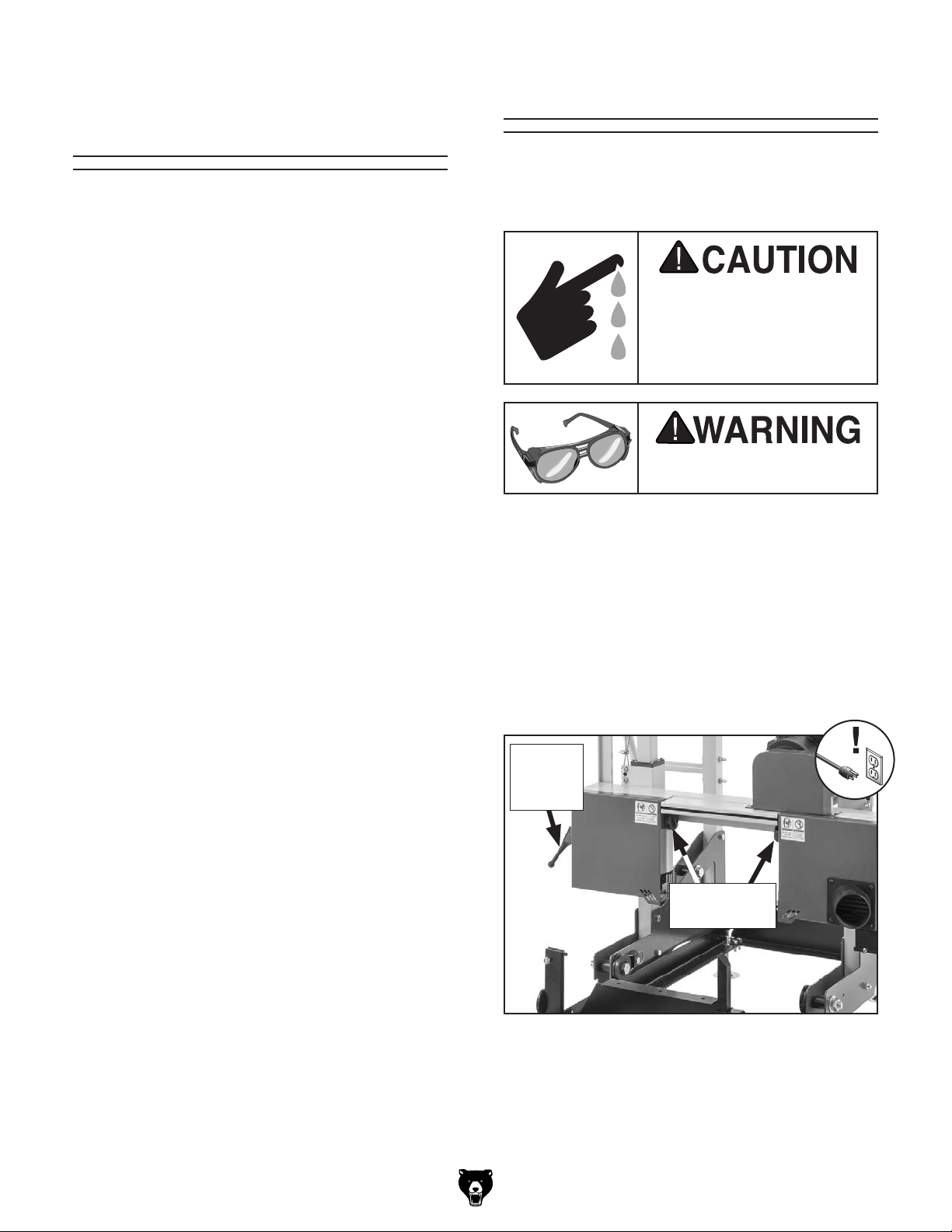
Workpiece Inspection
Some workpieces are not safe to cut or may
require modification before they are safe to cut.
Before cutting, inspect all workpieces for the
following:
Changing Blade
Blade changes entail removing the existing blade,
installing the new blade, then properly adjusting
the blade tension, tracking, and guides.
• Material Type: This machine is intended for
cutting natural wood logs only. The maximum
diameter of log that can be sawn is 13". This
machine is NOT designed to cut metal, glass,
stone, tile, etc.; cutting these materials with a
sawmill may lead to injury and machine/blade
damage.
• Debarking: Bark can trap and hide foreign
objects, such as tramp metal or hidden
nails, and can cause excessive blade wear.
Consider debarking your logs for increased
safety and longer blade life.
• Branches and Uneven Logs: Use a chain
saw or other saw to remove any branches
that prevent the log from lying evenly against
the track and log supports. Similarly, uneven
burls protruding from the log may need to be
removed before the log can be sawn.
Saw blades are sharp and
may cause lacerations. To
reduce the risk of injury,
wear leather gloves when
handling saw blades.
Wear safety glasses when
handling blade.
Removing Blade
1. DISCONNECT MACHINE FROM POWER!
2. Release blade tension by lifting lever or turn-
ing blade tension lever counterclockwise (see
Figure 63).
Turn blade cover lock knobs clockwise to
3.
open blade covers (see Figure 63).
Model G0960 (Mfd. Since 09/22)
Blade
Tension
Lever
Blade Cover
Lock Knobs
Figure 63. Location of blade tension lever and
blade cover lock knobs.
4. Remove blade from blade wheels and guides.
-35-

Installing Blade
1. DISCONNECT MACHINE FROM POWER!
Tensioning Blade
2. Hold blade on each side and position it in
front of wheels so blade teeth are facing front
of machine and pointing toward dust port.
Slide blade into blade guides, then slide
3.
blade over each wheel (see Figure 64).
Blade Wheels
Blade Guide
(1 of 2)
Figure 64. Blade installed in guides and around
wheels.
4. Adjust blade tension (see Tensioning
Blade), blade tracking (see Adjusting Blade
Tracking on Page 38), then adjust guides
(see Adjusting Blade Guides on Page 39).
A properly tensioned blade is essential for making
accurate cuts, maximizing blade life, and making
other adjustments. However, a properly tensioned
blade will not compensate for cutting problems
caused by excessive feed rate, hardness variations between workpieces, and improper blade
selection.
An over-tensioned blade increases the chance of
the blade breaking or wheel misalignment. Undertensioned blades wander excessively while cutting and will not track properly during operation.
IMPORTANT: Always release blade tension when
storing machine. Storing the blade with high blade
tension for an extended time period can deform
blade and weaken tensioning spring, reducing the
durability and accuracy of the machine.
Saw blades are sharp and
may cause lacerations. To
reduce the risk of injury,
wear leather gloves when
handling saw blades.
Close blade covers and secure with lock
5.
knobs.
-36-
Wear safety glasses when
handling blade.
To tension blade:
1. DISCONNECT MACHINE FROM POWER!
Model G0960 (Mfd. Since 09/22)

Turn blade cover lock knobs clockwise to
2.
open blade covers (see Figure 65).
Blade Cover
Lock Knobs
Figure 65. Location of blade cover lock knobs.
3. Push blade tension lever down to engage ten-
sion if not already done (see Figure 66), then
turn lever clockwise to tension blade, watching blade until proper tension is achieved. If
blade shifts or does not sit squarely on blade
wheels during step, release tension, reposition blade, then re-tension.
Note: Refer to blade tension scale shown in
Figure 67 to adjust blade tension for installed
blade width.
Blade Tension
Scale
Figure 67. Location of blade tension scale.
4. Close blade covers and secure with lock
knobs.
Blade Tension
Lever
Figure 66. Blade tension lever in down position.
Model G0960 (Mfd. Since 09/22)
-37-

Adjusting Blade
3. Center blade on wheels, then tension blade
(see Tensioning Blade on Page 36).
Tracking
Checking Blade Tracking
"Trac ki ng " refers to how the blade rides on the
sawmill wheels. Proper tracking is important for
achieving correct blade tension and cutting accurately. Improper tracking reduces cutting accuracy, causes excess vibration, and places stress on
the blade and other components. The orientation
of the wheels in relation to each other determines
how the blade tracks.
Saw blades are sharp and
may cause lacerations. To
reduce the risk of injury,
wear leather gloves when
handling saw blades.
4. Rotate wheels by hand and observe blade
position. Blade should track in center of
wheels and blade gullets should track about
1
⁄64" in front of blade guides (see Figure 69).
1
/64" or 0.016"
Blade
Blade
Gullets
Figure 69. Blade guide positioned
blade gullets.
Guide
1
⁄64" behind
Wear safety glasses when
handling blade.
To check blade tracking:
1. DISCONNECT MACHINE FROM POWER!
Turn blade cover lock knobs clockwise to
2.
open blade covers (see Figure 68).
Blade Cover
Lock Knobs
— If blade does remain centered on wheels,
and blade gullets do remain
blade guides, no adjustment is necessary.
— If blade does not remain centered on
wheels, or blade gullets do not remain
1
⁄64" in front of blade guides, proceed to
Adjusting Blade Tracking.
1
⁄64" in front of
Adjusting Blade Tracking
If blade tracking is out of alignment, the left wheel
shaft can be adjusted.
If adjusting the wheel shaft does not improve blade
tracking, adjust the blade guides, as blade guides
out of adjustment can make the blade wobble or
wander. If the blade is properly tensioned, the
blade guides have been properly adjusted, and
adjusting the wheel shaft still does not improve
blade tracking, replace the blade. A worn blade
can become "bell mouthed" and throw off wheel
coplanarity just enough to cause problems.
Figure 68. Location of blade cover lock knobs.
-38-
Tools Needed Qty
Hex Wrench 3mm .............................................. 1
Open-End Wrench
1
⁄2 " ....................................... 1
Model G0960 (Mfd. Since 09/22)

To adjust blade tracking:
1. DISCONNECT MACHINE FROM POWER!
Loosen blade guide assembly adjustment
2.
screws on each blade guide (see Figure 70)
so you can slide blade guides away from
blade so they will not interfere in the following
steps.
— Turn tracking knob clockwise to adjust
blade backward on left blade wheel.
— Turn tracking knob counterclockwise to
adjust blade forward on left blade wheel.
Note: Adjust blade tracking knob in 1⁄2 turn
increments, then tension blade and recheck
blade tracking as described in Checking
Blade Tracking on Page 38.
Blade Guide
Assembly
Adjustment Screw
Figure 70. Location of blade guide assembly
adjustment screw.
3. Turn blade tension lever counterclockwise
one full turn (see Figure 71).
Loosen jam nut on blade tracking knob (see
4.
Figure 71), then turn blade tracking knob to
adjust tracking.
Once blade tracking has been adjusted cor-
5.
rectly, tighten blade tracking jam nut to
secure.
Refer to Adjusting Blade Guides to adjust
6.
blade guides to blade.
Adjusting
Blade Guides
The blade guides can be adjusted top-to-bottom
and front-to-back relative to the blade. Properly
adjusted blade guides firmly support the blade
position along the cutting section of the blade.
After changing the blade, or if milling operations
produce inconsistent cuts, adjust the ceramic
blade guides and support bearings as described
in the following sections.
Blade
Tracking
Knob
Blade Tension
Lever
Figure 71. Location of blade tension lever and
blade tracking knob.
Model G0960 (Mfd. Since 09/22)
IMPORTANT: To ensure best results while cutting, make sure the blade is tracking and tensioned correctly before performing these procedures (see Tensioning Blade on Page 36 and
Adjusting Blade Tracking on Page 38).
Adjusting Blade Guide Assemblies
When properly adjusted, there is about 0.016"
between the blade gullets and the front of the
blade guides.
Items Needed Qty
Calipers ............................................................. 1
Hex Wrench 3mm
.............................................. 1
-39-

To adjust blade guide assemblies:
1. DISCONNECT MACHINE FROM POWER!
Loosen blade guide assembly adjustment
2.
screw (see Figure 72) so you can slide blade
guide assembly forward and backward.
Adjusting Blade Support Bearings
When properly adjusted, there is about 0.040"
between the blade support bearings and the
blade.
Items Needed Qty
Feeler Gauge 1mm (0.040") .............................. 1
Hex Wrench 3mm
.............................................. 1
Blade Guide
Assembly
Adjustment Screw
Blade
Guides
Blade Guide
Assembly
Figure 72. Location of blade guide assembly
and adjustment screw.
3.
Adjust blade guide assembly until there is
about 0.016" between front of blade guide
and blade gullets (see Figure 73).
1
/64" or 0.016"
To adjust blade support bearings:
1. DISCONNECT MACHINE FROM POWER!
Loosen support bearing adjustment screw on
2.
blade guide (see Figure 71) so you can slide
bearing forward and backward.
Support Bearing
Adjustment Screw
Support
Bearing
Figure 74. Location of support bearing and
adjustment screw.
3. Adjust support bearing until there is about
0.040" between front of support bearing and
back of blade (see Figure 75).
Blade
Blade
Guide
Gullets
Figure 73. Blade guide positioned 0.016" behind
blade gullets.
4.
Tighten blade guide assembly adjustment
screw to secure.
Repeat Steps 2–4 on second blade guide
5.
assembly.
-40-
Back of Blade
3
/64" or 0.040"
Support Bearing
Figure 75. Support bearing positioned 0.040"
behind back of blade.
Model G0960 (Mfd. Since 09/22)
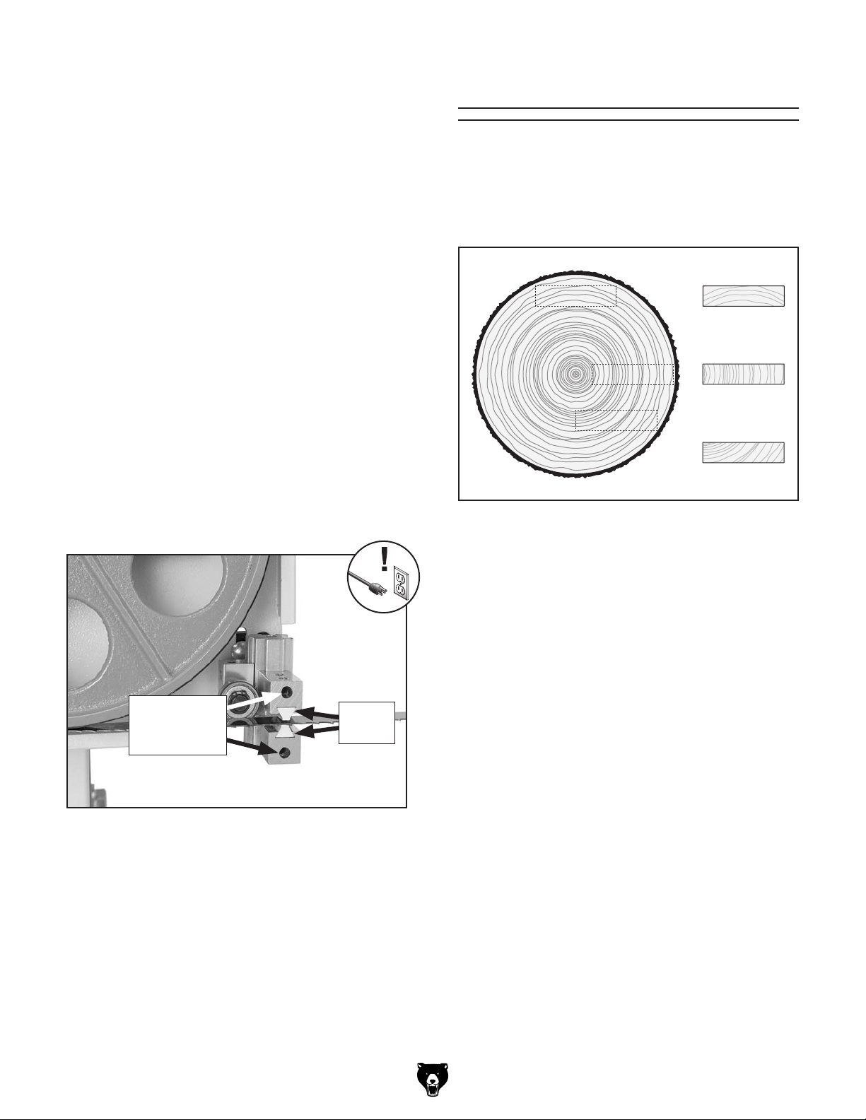
4. Tighten support bearing adjustment screw to
secure.
Repeat Steps 2–4 on second blade guide
5.
assembly.
Adjusting Blade Guides
The blade guides should sit about 0.010" on either
side of the blade.
Types of Lumber
The orientation of the woodgrain on a piece of
wood has a large impact on the attributes of the
lumber. Whether it is for structural, aesthetic, or
economic reasons, it is important for a sawyer to
know the output of their labors.
Items Needed Qty
Hex Wrench 3mm .............................................. 1
Feeler Gauge 0.25mm (0.010")
To adjust blade guides:
1. DISCONNECT MACHINE FROM POWER!
2. Loosen blade guide adjustment screws
shown in Figure 76.
Adjust blade guides until there is about
3.
0.010" between them and either side of blade
(about the thickness of sheet of paper) (see
Figure 76).
Blade Guide
Adjustment
Screws
......................... 1
Blade
Guides
Flatsawn
Quartersawn
Riftsawn
Figure 77. Types of lumber taken from a log.
Flatsawn Lumber (Plainsawn)
Flatsawn lumber is characterized by woodgrain
that is less than 45° to the face of the lumber,
called "tangential grain."
This often results in unique cathedral patterns on
the face of the lumber. However, the tangential
grain contributes to more cupping and twisting
during drying. Because flatsawn lumber is fastest and most plentiful to produce, it is the most
affordable lumber on the market. The majority of
construction quality lumber is flatsawn.
Figure 76. Location of blade guides and
adjustment screws.
4.
Tighten blade guide adjustment screws to
secure.
Repeat Steps 2–4 on second blade guide
5.
assembly.
Model G0960 (Mfd. Since 09/22)
Quartersawn Lumber
Quartersawn lumber is characterized by woodgrain
nearly perpendicular to the board. By some definitions, quartersawn lumber has grain more than
45° to the face of the lumber. In this manual,
quartersawn refers to lumber with grain between
75°–90° to the face.
-41-
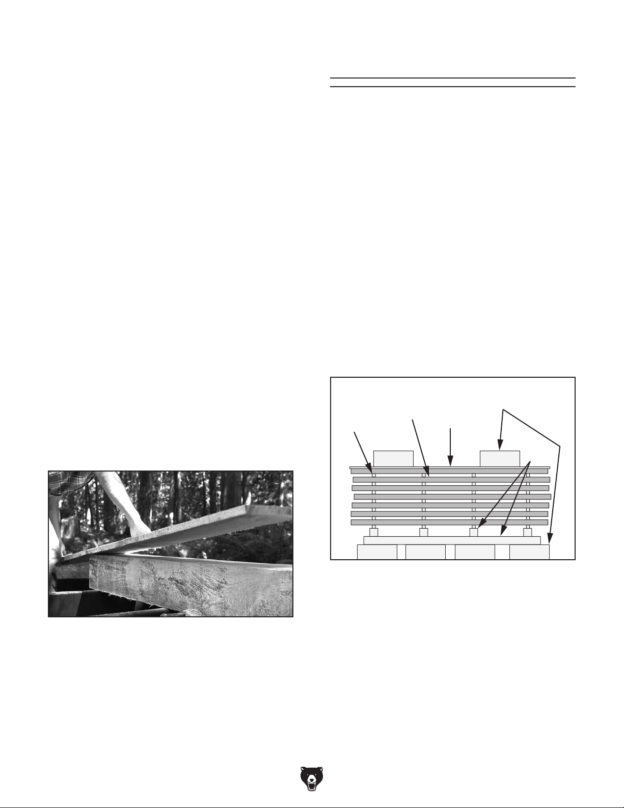
Quartersawn lumber is less likely to cup or twist
when dried. However, producing perfectly quarter sawn lumber is typically time consuming and
wastes a large volume of wood.
Some types of wood, such as white oak, show ray
flecks on the surface of the board when quartersawn, which is highly sought after by woodworkers. Taking the time to produce more quarter
sawn lumber can pay off, but it is important to
know what you are sawing and how the lumber
will be used before putting in the extra work.
Riftsawn Lumber
Sometimes classified as a type of quartersawn
lumber, riftsawn lumber is characterized by
woodgrain between 45°–70° to the face of the
lumber. It will never have perfectly perpendicular
woodgrain or show ray flecks.
Riftsawn lumber is often the by-product of quarter
sawing methods. Many sawyers consider riftsawn
lumber to be a happy medium between structural
integrity and milling time.
Drying Lumber
Before cutting your first log, have a plan for drying your lumber. Depending on the species of
wood, a green log might have anywhere from
60%–180% moisture content, and needs to be
dried to approximately 6%–11% before it can be
finished and used.
With the moisture loss, lumber will shrink and
warp. Depending on the drying conditions and
species of wood, air-drying can take anywhere
from several weeks to many months.
The most common method is air-drying, in which
freshly cut lumber is stacked outdoors with stickers and weights and the ends are sealed with
latex paint. Weighing down the stack and sealing
the board ends help to minimize warping as the
wood shrinks. When the lumber reaches approximately 20% moisture content, the stack is moved
indoors until drying is complete.
Cants
Cants are sawn logs with at least one finished
side. Cants with four finished sides are often used
in construction or resawn into smaller pieces of
dimensional lumber.
Figure 78. Example of live sawing a cant into
dimensional lumber.
Drying
Wood
Sticker
Figure 79. Side view of an air-drying stack.
Tracking moisture content can be done by regularly weighing and recording several of the drying boards. When the rate of weight loss slow
or stops, the wood has stopped drying. Moisture
meters (see Page 48) provide a fast and accurate
alternative to weight tracking.
Plywood
Cinderblock
4x4
-42-
Due to the many variables involved in drying lumber, it is important to research and plan for your
specific needs. Understand the drying environment and type of wood in order to ensure the end
product meets your needs.
Model G0960 (Mfd. Since 09/22)

Cant Sawing
Sawing a log into a square cant is a fundamental
sawing operation for any sawyer. When sawing a
cant, slabs are removed from four sides of the log,
leaving a square beam.
Note: It is essential that cut face of cant is
secured perpendicular to track on first rotation. When first (2) cuts are perpendicular,
remaining sides will be easy to square to log
supports.
5. Cut slab from top of log to remove second
slab.
To saw a cant:
1. Inspect log and determine size of cant to be
produced. Mark planned cuts on end of log.
Load log on track bed and secure with log
2.
supports and clamps.
Cut slab from top of log and remove it (see
3.
Figure 80).
Slab
Log
First Cut
Log
Clamp
Support
6. Remove log supports from bunks so cant
corner can press flush against support blocks
shown in Figure 82 when secured with log
clamps for remaining cuts.
Square Cant
Support Blocks
Figure 82. Location of square cant support
blocks.
Rotate cant 90° and secure against log sup-
7.
port blocks with log clamps (see Figure 83).
Figure 80. First cut to saw a cant.
4.
Rotate cant 90° and secure against log sup-
ports with log clamps to ensure cant is square
to track (see Figure 81).
Slab
Second Cut
Figure 81. Cant rotated for second cut.
Model G0960 (Mfd. Since 09/22)
Log
Support
Block
Figure 83. Example of cant secured against log
support blocks.
8. Cut slab from top of log to remove third slab.
9. Repeat Steps 7–8 to remove final slab from
cant.
10. If square cant was goal of operation, congratulations, you are finished! To cut cant into
dimensional labor, proceed to Live Sawing.
-43-
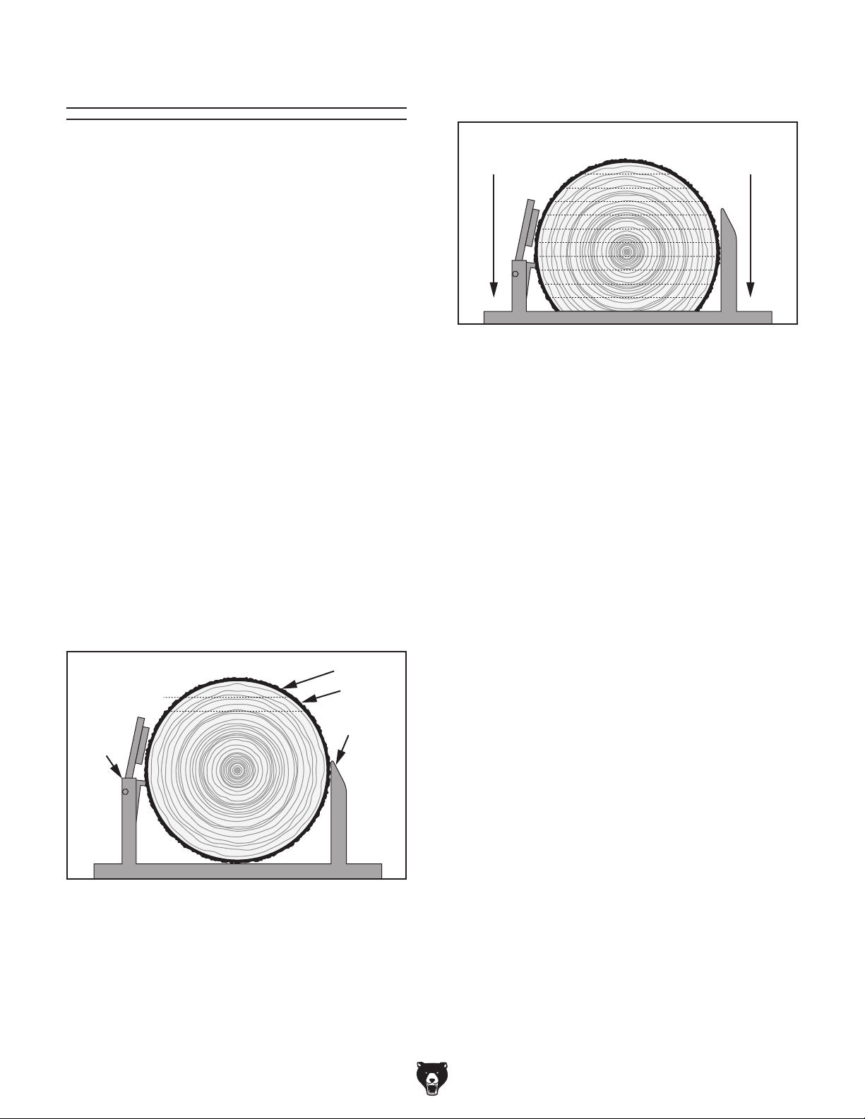
Live Sawing
Cut Entire Log
Rotate log 180° and secure with log supports
5.
and clamps (see Figure 85).
Live sawing is a method of sawing logs that is fast
and produces very little wasted wood. In a live
sawing procedure, the log is cut from top to bottom and is rarely rotated more than once.
Lumber produced when live sawing will range
from flatsawn (cuts made near the top and bottom) to quartersawn (cuts made near the middle
of the log). Because no specific type of lumber is
prioritized, live sawing maximizes the amount of
board feet produced per log.
To live-saw a log:
1. Inspect log and outline a sawing plan.
Consider orientation of log on track and
where to start cutting to produce the best
lumber. Mark planned cuts on end of log.
Load log on track bed and secure with log
2.
supports and clamps.
Make first cut, then remove slab from log (see
3.
Figure 84).
Lower blade the desired thickness of lumber
4.
and cut first flitch (see Figure 84).
Slab
First Cut
Second Cut
Log
Clamp
Flitch
Log
Support
Top to Bottom
Figure 85. Log rotated 180° for live sawing.
Note: Logs can be live sawn from top to bot-
tom without being rotated, but rotating once
provides stable base to saw rest of log.
Continue to cut flitches from top to bottom
6.
until log is fully used. Adjust log supports
and clamps throughout process to keep them
below blade and to keep log secured.
7. Edge flitches as needed.
— If available, an edger can be used to
quickly and easily edge lumber.
— Without an edger, sawmill can be used.
Refer to Edging on Page 45.
Note: Live-sawing square cant will produce lum-
ber that does not need to be edged. However, it
typically produces more waste than live-sawing
log and edging it.
Figure 84. First cuts to live saw a log.
-44-
Model G0960 (Mfd. Since 09/22)

Edging
Repeat Steps 2–3 until all flitches have been
4.
edged once (see Figure 87).
Edging a flitch involves removing the natural or
waney edges, turning it into lumber with four finished sides. Using an edger is the quickest and
simplest way of edging, but edging can also be
done with a sawmill. For many sawyers running
singe-mill operations, using a mill for edging is
the default.
To edge flitches using a sawmill:
1. Clamp multiple flitches to track bed, using log
supports to ensure flitches are perpendicular
to track (see Figure 86). Take care that log
clamps hold flitches tight against supports.
Cut to remove bark from the tallest flitches.
2.
Cut as many flitches as possible without
wasting excessive lumber (see Figure 86).
First Cut
Second
Cut
Figure 87. Tallest flitches to be removed after
each cut.
5.
Clamp single-edged flitches to track bed,
using flat edges and log supports to ensure
flitches are perpendicular to track (see
Figure 88).
Third
Cut
Log
Clamp
Figure 86. Flitches secured to track bed for
edging.
3.
Remove edged flitches, then secure the rest
(see Figure 87).
Log
Support
Figure 88. Flitches secured to track in
preparation for second edging.
6.
Repeat Steps 2–3 until all flitches have been
edged on both sides.
Model G0960 (Mfd. Since 09/22)
-45-
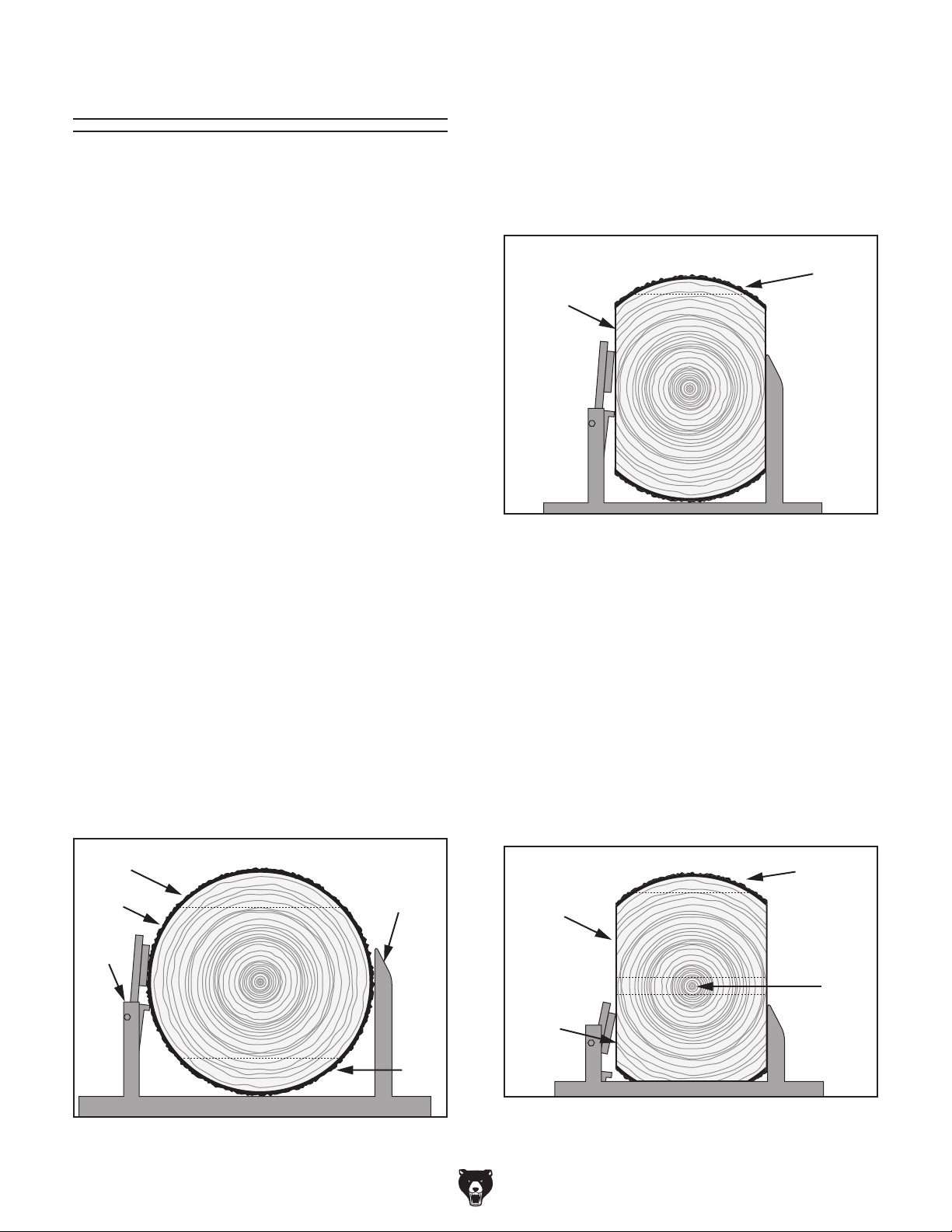
Quarter Sawing
Quarter sawing is any method of milling a log
that produces primarily quartersawn lumber. In
general, this produces a mixture of quartersawn
and riftsawn lumber. Producing only quartersawn
lumber can be time-consuming and leaves a lot
of scrap.
The method below is relatively simple and produces quartersawn and riftsawn lumber. Many
other methods exist—all with unique benefits and
downsides. A sawyer should choose a method
based on the log used, lumber needed, and personal preference.
To quarter-saw a log:
1. Inspect log and outline a sawing plan.
Consider orientation of log on track and
where to start cutting to produce the best
lumber. Mark planned cuts on end of log.
5.
Rotate cant 90° and clamp to track bed, using
log supports to ensure cant is perpendicular
to track (see Figure 90). Take care that log
clamps hold cant tight against supports.
Cut a thin slab and remove it from cant (see
6.
Figure 90). Discard slab.
Thin
Slab
Cant
Figure 90. Thin slab to be removed from cant.
Load log to track bed and secure with log
2.
supports and clamps.
Cut a thick slab and remove it from log (see
3.
Figure 89). Set slab aside for now.
Rotate log 180° and secure it. Cut a slab about
4.
the same size as the first one (see Figure
89). To reduce waste, make sure the distance
between cuts—the height of the resulting
cant—is divisible by the thickness of lumber to
be produced. Set slab aside for now.
Thick
Slab
Cant
Log
Clamp
Log
Support
7.
Rotate cant 180° and secure it.
8. Cut a thin slab and remove it from cant (see
Figure 91). Discard slab.
Cut above pith, then remove top cant from
9.
the cant secured to the track (see Figure 91).
Set top cant aside for now.
10. Cut below pith. To reduce waste, cut a board
that is a usable thickness when cutting below
pith. Remove board with pith from cant (see
Figure 91). Set board aside for now.
Thin
Slab
Cant
Pith
Thick
Slab
Figure 89. Thick slabs to be removed from log.
-46-
Cant
Figure 91. Two rectangular cants and pith to be
removed.
Model G0960 (Mfd. Since 09/22)

11. Rotate cant 90° and secure it.
Cut from top to bottom until cant is fully used
12.
(see Figure 92). Adjust log supports and
clamps throughout process to keep them
below blade and to keep log secured.
19.
Inspect end of slab and determine which
portion is suitable for quartersawn lumber.
Evaluate the width of the resulting lumber,
as well as the angle of the grain. Cut slab
where quartersawn quality wood begins (see
Figure 94).
Quartersawn
Lumber
Figure 92. Quartersawn lumber to be cut from
cant.
Load second cant to track bed, and secure
13.
with log supports and log clamps.
Repeat Step 12 with second cant.
14.
Clamp board with pith to track bed, using log
15.
supports to ensure board is perpendicular to
track (see Figure 93).
Cut just above pith, then remove resulting
16.
quartersawn board from board secured to
track (see Figure 93).
17. Cut just below pith. Remove and discard pith
(see Figure 93).
Scrap
Figure 94. Scrap wood to be cut from slab.
Rotate slab 180° and secure it.
20.
Cut slab where quartersawn quality wood
21.
begins, then continue to cut flitches from
top to bottom until slab is fully used (see
Figure 95).
Scrap
Quartersawn
Flitches
Quartersawn
Lumber
Figure 93. Pith to be removed from board.
18.
Load slab from Step 3 or 4 to track bed,
using log supports to ensure slab is perpendicular to track (see Figure 94). Take care
that log clamps are holding slab tight against
supports.
Model G0960 (Mfd. Since 09/22)
Pith
Figure 95. Quartersawn flitches to be cut from
slabs.
22. Repeat Steps 18–21 on remaining slab.
23. Edge all flitches and waney boards.
— If available, an edger can be used to
quickly and easily edge lumber.
— Without an edger, the sawmill can be
used. See Edging on Page 45.
-47-

ACCESSORIES
Installing unapproved accessories may
order online at www.grizzly.com or call 1-800-523-4777
SECTION 5: ACCESSORIES
cause machine to malfunction, resulting in
serious personal injury or machine damage.
To reduce this risk, only install accessories
recommended for this machine by Grizzly.
NOTICE
Refer to our website or latest catalog for
additional recommended accessories.
T30855 —AccuMASTER XT Moisture Meter
T30904—AccuMASTER Duo Pro Moisture Meter
These easy-to-use moisture meters are ideal for
measuring moisture content in logs and lumber.
The XT and Duo Pro also work with brick, concrete, drywall, plaster, and carpet so you can find
moisture before it becomes a costly problem.
T27630 —Lumber Rack 6-Shelf System
T31725 —Lumber Rack 3-Shelf System
Keep materials organized and accessible with
these lumber shelf systems. Easy to install into a
sturdy wall and each shelf can hold up to 100 lbs.
Figure 97. Lumber Rack Shelf Systems.
Figure 96. T30904 AccuMASTER Duo Pro
Pin & Pinless Moisture Meter.
T31851
With the ability to hold up to 600 pounds and 120
cubic feet of material, this steel garage or shop
rack drastically increases your storage capabilities and decreases clutter wherever you place it.
—Hanging Storage Rack
Figure 98. T31851 Hanging Storage Rack.
-48-
Model G0960 (Mfd. Since 09/22)

T33224—3 Ft. Bed Extension Rails
order online at www.grizzly.com or call 1-800-523-4777
These modular track extensions can be quickly
connected to your existing track to increase your
sawing capacity in 3' increments, allowing for
practically any length lumber that you need to mill.
Basic Eye Protection
T32323—Woodturners Face Shield
T32401—EDGE Brazeau Safety Glasses, Clear
T32402—EDGE Khor G2 Safety Glasses, Tint
T32404—EDGE Mazeno Safety Glasses, Clear
T32323 T32401
Figure 99. T33224 3 Ft. Bed Extension Rails.
T29242—Compact Cordless 12" Chainsaw
Gas-free operation on this 20V max DeWalt chainsaw eliminates the cold starts, fumes, carburetor
issues, and maintenance involved with gas-powered chainsaws. This battery-powered chainsaw
is built to work hard. Use it for tough construction
and outdoor jobs like cutting beams, demolition
work, and managing tree limbs. The lightweight
design maximizes user control. Brushless motor
technology delivers extreme runtime and long
motor life. Battery and charger not included.
T32402
Figure 101. Assortment of basic eye protection.
T30024—Powered Respirator Kit
Breathing wood dust could cause severe respiratory illnesses. This kit is a lightweight, comfortable, and easy-to-carry device for protecting the
airway from small particulates.
T32404
Figure 102. T30024 Powered Respirator Kit.
Figure 100. T29242 20V Max Compact Cordless
12" Chainsaw.
Model G0960 (Mfd. Since 09/22)
-49-

order online at www.grizzly.com or call 1-800-523-4777
D2828—12" Stainless Steel Ruler
H7971—3" Digital Caliper
T31828 —24" Bevel Straight Edge w/Scale
These high-quality, precision measuring tools are
perfect for adjusting your saw mill blade.
D2828
T31828
H7971
T32595—30" Cant Hook
T32592—48" Cant Hook
T32593—60" Cant Hook
T32594—48" Peavey
T32596—Two Man Log Carrier
T32597—36" Hookaroon
These log handling tools have blue aluminum
handles that are easy to spot around the shop.
T32592
Figure 103. Measuring tools.
T32598—International Log Scale w/Handle
This log scale from Logrite has an anodized blue
finish that highlights the laser etched numbers on
the scale. The finish also allows pitch to be easily removed with solvents without damaging the
printing.
Figure 104. T32598 International Log Scale with
Handle.
T32594
T32596
T32597
Figure 105. Log handling accessories.
-50-
Model G0960 (Mfd. Since 09/22)
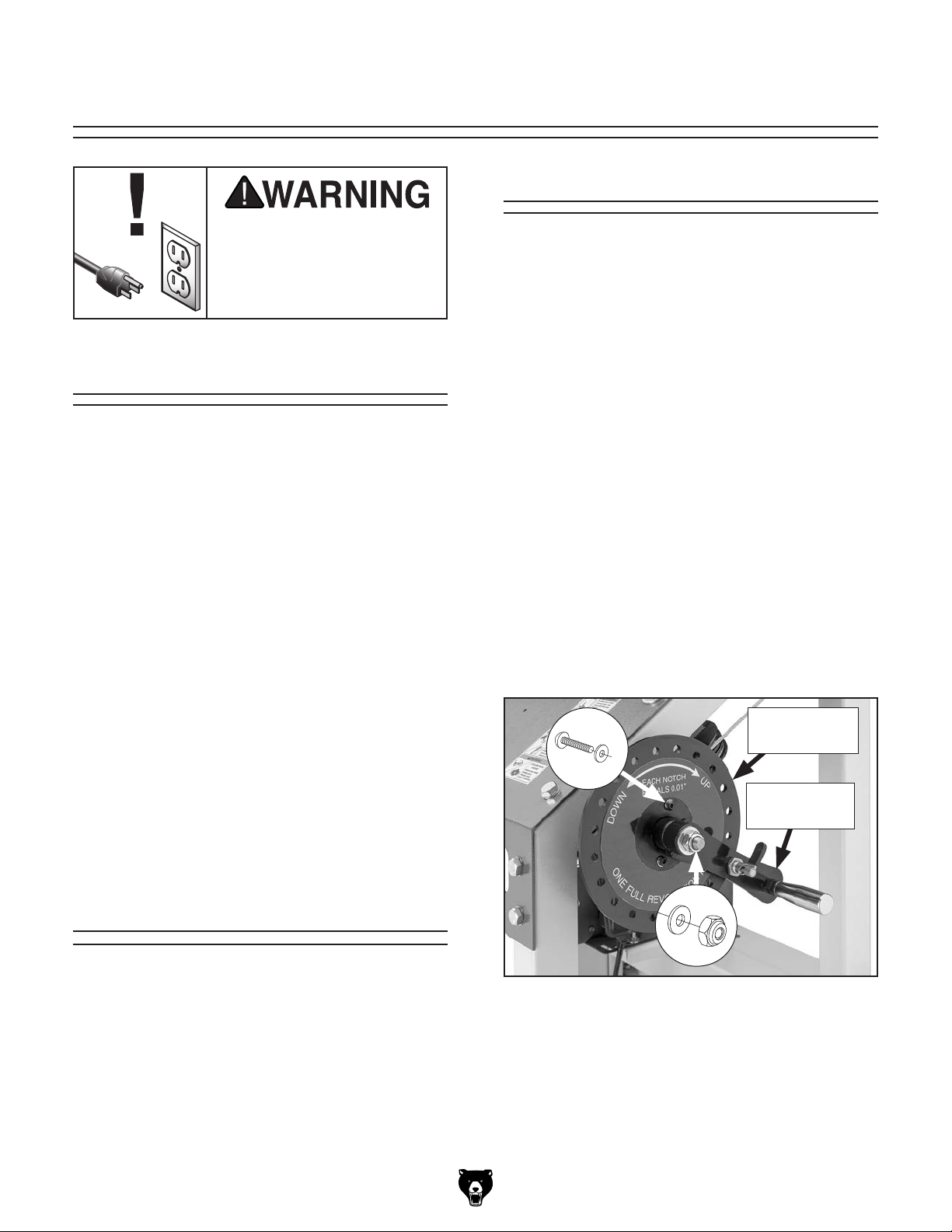
SECTION 6: MAINTENANCE
To reduce risk of shock or
accidental startup, always
disconnect machine from
power before adjustments,
Lubrication
Most of the bearings on this machine are sealed
and permanently lubricated. Leave these bearings alone until they need to be replaced. Do not
maintenance, or service.
Schedule
lubricate them.
Apply lubricant to the blade height thrust bearings
described below every 40 hours of use, before
storage, or as needed.
For optimum performance from this machine, this
maintenance schedule must be strictly followed.
Ongoing
To minimize your risk of injury and maintain proper
machine operation, shut down the machine immediately if you ever observe any of the items below,
and fix the problem before continuing operations:
• Loose mounting bolts.
• Dull or damaged saw blade.
Wood chip and sawdust buildup.
•
Frayed lift cables.
•
Worn or damaged wires.
•
Any other unsafe condition.
•
Weekly Maintenance
• Lubricate blade height thrust bearings.
Monthly Check
• V-belt tension, damage, or wear.
Items Needed Qty
Wrench or Socket 19mm ................................... 1
Hex Wrench 4mm
Light Machine Oil............................... As Needed
To lubricate machine:
Completely lower headstock so it is sup-
1.
ported on carriage legs.
Remove lock nut, (2) button head cap screws,
2.
and (3) flat washers shown in Figure 106 to
remove blade height handle and handwheel.
x 2
.............................................. 1
Blade Height
Handwheel
Blade Height
Handle
Cleaning
Cleaning the Model G0960 is relatively easy and
should be done whenever the machine operation
is finished for the day. Vacuum excess wood chips
and sawdust, and wipe off the remaining dust with
a dry cloth. If any resin has built up, use a resin
dissolving cleaner to remove it.
Model G0960 (Mfd. Since 09/22)
Figure 106. Location of blade height handwheel
fasteners.
Apply light machine oil to thrust bearings
3.
behind blade height handwheel, then install
handwheel.
Align blade height handle keyway with key,
4.
then install handle.
-51-

Review the troubleshooting procedures in this section if a problem develops with your machine. If you need
the
serial number and manufacture date of your machine before calling.
SECTION 7: SERVICE
replacement parts or additional help with a procedure, call our Technical Support. Note: Please gather
Troubleshooting
Motor & Electrical
Symptom Possible Cause Possible Solution
Machine does
not start, or
power supply
breaker
immediately
trips after
startup.
Machine
stalls or is
underpowered.
Machine has
vibration or
noisy operation.
1. Switch disabling key removed.
2. Machine circuit breaker tripped or at fault.
3. Incorrect power supply voltage or circuit size.
4. Plug at fault/wired incorrectly.
5. Power supply circuit breaker tripped or fuse
blown.
6. Motor wires connected incorrectly.
7. Start capacitor at fault.
8. Centrifugal switch adjustment/contact points
at fault.
9. Wiring broken, disconnected, or corroded.
10. ON/OFF or circuit breaker switch at fault.
11. Motor or motor bearings at fault.
1. Dull blade.
2. Feed rate too fast.
3. Workpiece moves/not secure on track.
4. Machine undersized for task.
5. Blade slipping on wheels or not properly
tensioned.
6. Belt slipping/pulleys misaligned.
7. Motor wires connected incorrectly.
8. Plug at fault/wired incorrectly.
9. Pulley slipping on shaft.
10. Motor overheated, tripping machine circuit
breaker.
11. Run capacitor at fault.
12. Extension cord too long.
13. Centrifugal switch adjustment/contact points
at fault.
14. Motor or motor bearings at fault.
1. Excessive sawdust buildup inside saw
headstock.
1. Install switch disabling key.
2. Reset circuit breaker.
3. Ensure correct power supply voltage and circuit size
(Page 12).
4. Test for good contacts; correct wiring (Page 62).
5. Ensure circuit is free of shorts. Reset circuit breaker or
replace fuses.
6. Correct motor wiring connections (Page 62).
7. Test/replace if at fault.
8. Adjust centrifugal switch/clean contact points. Replace
either if at fault.
9. Fix broken wires or disconnected (Page 62)/corroded
connections.
10. Replace switch/circuit breaker.
11. Replace motor.
1. Sharpen/replace blade.
2. Decrease feed rate.
3. Secure log against supports; remove branches or
lumps that prevent even positioning.
4. Use correct blade/reduce feed rate or depth of cut.
5. Adjust blade tracking (Page 38) and tension
(Page 36).
6. Clean/tension (Page 55)/replace belt (Page 56);
ensure pulleys are aligned.
7. Correct motor wiring connections (Page 62).
8. Test for good contacts; correct wiring (Page 62).
9. Tighten/replace loose pulley/shaft.
10. Clean motor, let cool, and reduce workload. Reset
breaker.
11. Test/repair/replace.
12. Move machine closer to power supply; use shorter
extension cord.
13. Adjust centrifugal switch/clean contact points. Replace
either if at fault.
14. Replace motor.
1. Vacuum excess chips and sawdust.
-52-
Model G0960 (Mfd. Since 09/22)

Motor & Electrical (Cont.)
Symptom Possible Cause Possible Solution
Machine has
vibration or
noisy operation.
2. Motor or component loose.
3. Track feet not adjusted correctly.
4. Workpiece moves/not secure on track.
5. Blade weld at fault/teeth broken.
6. V-belt worn, loose, pulleys misaligned or belt
slapping cover.
7. Pulley loose.
8. Wheel bearings at fault.
9. Motor fan rubbing on fan cover.
10. Centrifugal switch needs adjustment/at fault.
11. Motor bearings at fault.
2. Replace damaged or missing bolts/nuts or tighten if
loose.
3. Adjust track feet to stabilize track and machine.
4. Secure log against supports; remove branches or
lumps that prevent even positioning.
5. Replace blade.
6. Inspect/replace belt (Page 56). Realign pulleys if
necessary.
7. Secure pulley on shaft.
8. Replace wheel bearings.
9. Fix/replace fan cover; replace loose/damaged fan.
10. Adjust/replace if at fault.
11. Test by rotating shaft; rotational grinding/loose shaft
requires bearing replacement.
Operation
Symptom Possible Cause Possible Solution
Finished
workpieces are
wavy, crooked
or uneven.
Finished
workpieces
have rough
surface.
Blade dulls
prematurely.
Blade tension
scale is
inaccurate.
Sawdust
buildup inside
saw headstock.
1. Blade is not properly tensioned.
2. Excessive feed rate/pressure.
3. Track is not level.
4. Log not parallel to track or cant not square to
log supports.
5. Blade tracking is incorrect.
6. Wrong blade type or TPI for cut type.
7. Dull or damaged blade, or blade installed
backwards.
8. Blade guides or support bearings worn or
misadjusted.
1. Blade is not properly tensioned.
2. Excessive feed rate/pressure.
3. Blade tracking is incorrect.
4. Wrong blade type or TPI for cut type.
5. Blade has missing or bent teeth or faulty
weld.
1. Blade is not properly tensioned.
2. Excessive feed rate/pressure.
3. Wrong blade type or TPI for cut type.
4. Hard spots in material.
5. Blade installed inside-out.
6. Blade is twisted or damaged.
7. Foreign objects or tramp metal in log.
1. Blade tension spring is worn or damaged. 1. Replace spring. Release blade tension when not in
1. Clogged dust port.
2. Dust collection CFM is too low.
1. Adjust blade tension (Page 36).
2. Reduce feed rate/pressure.
3. Tighten track fasteners; adjust track feet until track is
level.
4. Secure log against supports; remove branches or
lumps that prevent even positioning.
5. Adjust blade tracking (Page 38).
6. Use correct blade for cutting type.
7. Replace blade or re-install blade (Page 36).
8. Adjust blade guides or support bearings for correct
blade support (Page 39).
1. Adjust blade tension (Page 36).
2. Reduce feed rate/pressure.
3. Adjust blade tracking (Page 38).
4. Use correct blade for cutting type.
5. Replace blade.
1. Adjust blade tension (Page 36).
2. Reduce feed rate/pressure.
3. Use correct blade for cutting type.
4. Increase feed pressure.
5. Re-install blade (Page 36).
6. Replace blade (Page 36).
7. Check log for foreign objects or tramp metal. Use
different log if necessary.
use and do not over-tension blade.
1. Clean dust port.
2. Use dust collector with higher CFM (Page 32).
Model G0960 (Mfd. Since 09/22)
-53-

Operation (Cont.)
Symptom Possible Cause Possible Solution
Blade tracks
incorrectly
or comes off
wheels.
Blade or teeth
break during
operation.
Blade slows
when cutting.
Blade does not
cut.
Blade is
twisting during
cut.
Last board
is tapered
or narrow in
middle.
1. Blade tracking is incorrect.
2. Blade is not properly tensioned.
3. Excessive feed rate/pressure.
4. Wrong blade type or TPI.
5. Belt is worn.
6. Dull or damaged blade.
7. Blade wheels are not coplanar.
8. Blade guides too tight against blade.
9. Wheel tire(s) damaged or worn.
1. Log is loose.
2. Foreign objects or tramp metal in log.
3. Blade is not properly tensioned.
4. Excessive feed rate/pressure.
5. Blade teeth clogged.
6. Wrong blade type or TPI.
7. Blade tracking is incorrect.
8. Dull or damaged blade.
9. Wheel tires worn or incorrectly installed.
10. Bad bearings on wheels.
1. Blade is not properly tensioned.
2. Excessive feed rate/pressure.
3. Dull or damaged blade.
4. Blade installed backwards.
5. V-belt is loose or slipping.
6. Belt is worn.
7. Blade guides worn or misadjusted.
8. Blade wheels are not coplanar.
1. Dull or damaged blade.
2. Blade installed backwards.
1. Blade is not properly tensioned.
2. Excessive feed pressure.
3. Dull or damaged blade.
1. Track is not level.
2. Saw headstock and blade are not parallel to
log bunks.
1. Adjust blade tracking (Page 38).
2. Adjust blade tension (Page 36).
3. Reduce feed rate/pressure.
4. Use correct blade.
5. Replace belt (Page 56).
6. Replace blade (Page 36).
7. Adjust wheels to be coplanar (Page 58).
8. Adjust blade guides (Page 39).
9. Replace wheel tire(s).
1. Secure log against supports; remove branches or
lumps that prevent even positioning.
2. Check log for foreign objects or tramp metal. Use
different log if necessary.
3. Adjust blade tension (Page 36).
4. Reduce feed rate/pressure.
5. Clean blade.
6. Use correct blade.
7. Adjust blade tracking (Page 38).
8. Replace blade (Page 36).
9. Replace or re-install tire.
10. Replace wheel bearings.
1. Adjust blade tension (Page 36).
2. Reduce feed rate/pressure.
3. Replace blade (Page 36).
4. Re-install blade (Page 36).
5. Tension V-belt (Page 55).
6. Replace belt (Page 56).
7. Adjust blade guides for correct blade support
(Page 39).
8. Adjust wheels to be coplanar (Page 58).
1. Replace blade (Page 36).
2. Re-install blade (Page 36).
1. Adjust blade tension (Page 36).
2. Reduce feed pressure.
3. Replace blade (Page 36).
1. Level track.
2. Adjust saw headstock and blade parallel to log bunks
(Page 30).
-54-
Model G0960 (Mfd. Since 09/22)

Tensioning/
Replacing V-Belt
3. Turn right blade cover lock knob clockwise to
open right blade cover (see Figure 107).
The V-belt transfers power from the motor to the
wheels. The blade and V-belt must be tensioned
properly to ensure proper operation. It is essential
that the V-belt is free of cracks, fraying, and wear.
V-belt condition and tension should be checked at
least every 3 months —more often if the sawmill is
used daily.
To replace the V-belt, you must remove the blade.
After installation, you must re-tension the V-belt.
V-belt and pulleys will be hot after operations.
Allow them to cool before checking tension
or handling V-belt.
Checking V-Belt Tension
To ensure optimum power transmission from the
motor to the blade, the V-belt must be properly
tensioned.
V-Belt
Cover
Right Blade
Cover
Lock Knob
Figure 107. Location of right blade cover lock
knob, V-belt cover, and fasteners.
Inspect V-belt (see Figure 108); if it is dam-
4.
aged or glazed, replace it (see Page 56).
x 2
Items Needed Qty
Wrench or Socket 10mm ................................... 1
Open-End Wrench
Another Person
To check V-belt tension:
1. DISCONNECT MACHINE FROM POWER!
Remove (2) hex bolts and flat washers shown
2.
in Figure 107 to remove V-belt cover.
1
⁄2 " ....................................... 1
.................................................. 1
V-Belt
Figure 108. Location of V-belt.
Model G0960 (Mfd. Since 09/22)
-55-
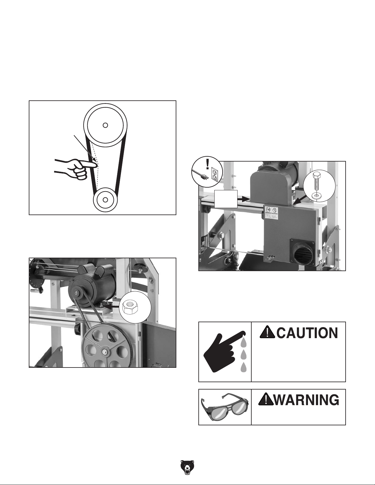
5.
Check V-belt tension by applying moderate
pressure between pulleys (see Figure 109).
— If deflection is approximately 1⁄4", no adjust-
ment is necessary.
— If deflection is not approximately 1⁄4", belt is
not correctly tensioned. Proceed to Step 6.
Replacing V-Belt
Items Needed Qty
Wrench or Socket 10mm ................................... 1
Protective Gloves..........................................1 Pr.
Safety Glasses
Open-End Wrench
Replacement V-Belt (#P09602059)
Another Person
To replace V-belt:
.............................................1 Pr.
1
⁄2 " ....................................... 1
................... 1
.................................................. 1
Bandsaw
Wheel
Deflection
1
⁄4"
Motor
Wheel
Figure 109. V-belt deflection.
6. Loosen (4) motor mounting hex nuts (see
Figure 110).
1. DISCONNECT MACHINE FROM POWER!
Remove (2) hex bolts and flat washers shown
2.
in Figure 111 to remove V-belt cover.
x 2
V-Belt
Cover
Figure 111. Location of V-belt cover and
fasteners.
x 4
Figure 110. Location of motor mounting hex
nuts.
7. Have assistant adjust motor position until
1
deflection is approximately
⁄4", then tighten
hex nuts from Step 6.
Close and secure right blade cover and install
8.
V-belt cover.
-56-
3. Perform Steps 2–4 of Removing Blade on
Page 36 to remove blade from wheels.
Saw blades are sharp and
may cause lacerations. To
reduce the risk of injury,
wear leather gloves when
handling saw blades.
Wear safety glasses when
handling blade.
Model G0960 (Mfd. Since 09/22)

4. Loosen (4) motor mounting hex nuts (see
Figure 112) to release belt tension.
x 4
V-Belt
Figure 112. Location of V-belt and motor
mounting hex nuts.
Slip old V-belt off pulleys, then install new belt
5.
in its place.
6. Have assistant adjust motor position
until deflection is approximately
Figure 113), then tighten hex nuts from
Step 4.
Deflection
1
⁄4" (see
Bandsaw
Wheel
Calibrating Blade
Height Scale
Use the following steps to adjust the scale indicator so it is equal to the distance between the blade
and the log bunks.
Item Needed Qty
Measuring Tape ................................................. 1
To calibrate blade height scale:
1. DISCONNECT MACHINE FROM POWER!
Confirm that blade tension (Page 36) and
2.
blade guides (Page 39) have been adjusted
correctly.
Confirm saw head is level by performing
3.
Steps 63–65 of Assembly on Page 30.
Measure distance between back of blade to
4.
top of log bunk.
— If distance between back of blade and log
bunk is equal to value shown on scale, no
adjustment is necessary.
— If distance between back of blade and log
bunk is not equal to value shown on scale,
proceed to Step 5.
1
⁄4"
Motor
Wheel
Figure 113 . V-belt deflection.
7.
Perform Steps 2–5 of Installing Blade on
Page 36 to install blade.
Install V-belt cover.
8.
Model G0960 (Mfd. Since 09/22)
Loosen knob shown in Figure 114, adjust
5.
indicator to value measured in Step 4, then
tighten knob to secure.
Scale Indicator
Knob
Scale Indicator
Figure 114. Location of scale indicator knob.
-57-

Adjusting
Wheel Alignment
The following adjustment was performed at the
factory and should not need to be performed
unless there is a wheel alignment problem, or one
or more wheels are replaced.
When wheels are coplanar (see Figure 115),
the saw mill is more likely to cut straight without
wandering; and vibration, heat, and blade wear
are considerably decreased because the blade is
automatically balanced on the wheels.
Wheels parallel and coplanar.
Checking Wheel Alignment
Tool Needed Qty
Straightedge 3' .................................................. 1
To check wheel alignment:
DISCONNECT MACHINE FROM POWER!
1.
2. Turn blade cover lock knobs clockwise to
open blade covers (see Figure 116).
Blade Cover
Lock Knobs
or
Wheels parallel, but not coplanar.
Left wheel is not laterally aligned
with right wheel.
Right wheel is not vertically
aligned with left wheel.
Figure 116. Location of blade cover lock knobs.
3. Place straightedge up against both wheels
in positions shown in Figure 117. Make sure
straightedge fully extends across rims of both
wheels.
Tracking
Knob
Straightedge
Wheels
Gauge Positions
Adjustment
Hub
Figure 115. Wheel alignment illustration.
Bringing the wheels into alignment may require a
combination of shimming a wheel and adjusting
the position of the left wheel shaft.
-58-
Figure 117. Illustrations of using straightedge to
check wheel alignment.
Model G0960 (Mfd. Since 09/22)

4. Check wheel alignment and adjust tracking
knob to bring both wheels into alignment as
much as possible. If wheels cannot be adjusted coplanar, use Figure 118 to determine
how to proceed with alignment adjustments.
Items Needed Qty
Straightedge 3' .................................................. 1
Fine Ruler
Shims
Wrench or Socket 10mm
.......................................................... 1
................................................. As Needed
................................... 1
To shim a wheel:
1. DISCONNECT MACHINE FROM POWER!
Wheels parallel and
aligned: No adjustment
needed.
or
Wheels parallel, but right or left wheel is
not coplanar with the other wheel: Move
the left wheel in or out.
Left wheel is not laterally aligned
with right wheel: Use blade tracking
knob to tilt left wheel.
Adjust left wheel tracking so that it is parallel
2.
with right wheel.
With straightedge touching both rims of wheel
3.
that does not need to be shimmed, measure
distance away from other wheel with fine ruler
(see Figure 119). Distance measured with
ruler is distance wheel must be shimmed.
Figure 119. Example of measuring distance to
shim wheel to make it coplanar with other wheel.
Right wheel is not vertically
aligned with left wheel: Adjust rear
adjustment set bolts to tilt right
wheel up/down.
Figure 118. Wheel alignment illustration with
solutions to misalignment problems.
Shimming a Wheel
When the wheels are parallel but not coplanar,
one of the wheels must be shimmed out to bring it
into the same plane as the other wheel.
Tip: Standard washers work well for shimming a
wheel because they can easily be stacked to get
the desired depth.
Model G0960 (Mfd. Since 09/22)
Saw blades are sharp and
may cause lacerations. To
reduce the risk of injury,
wear leather gloves when
handling saw blades.
Wear safety glasses when
handling blade.
4. Close blade covers, detension blade, then
open blade covers and remove blade from
wheels.
-59-
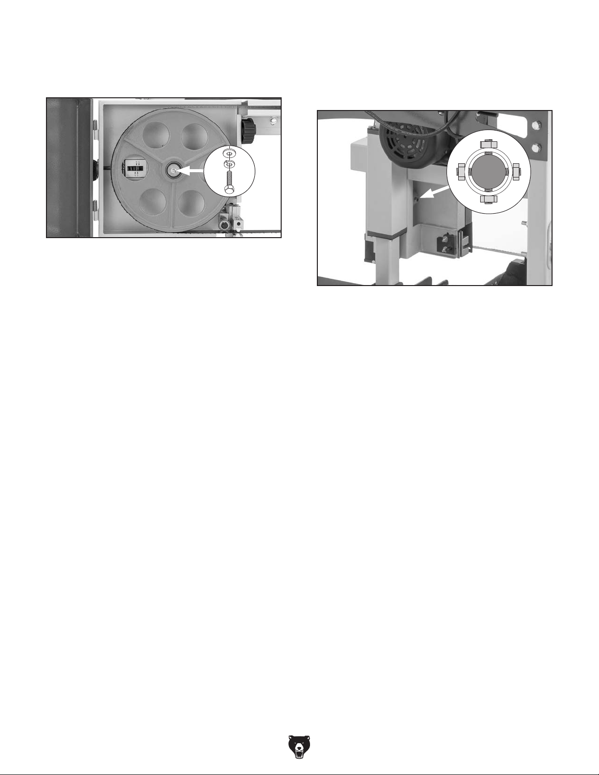
Remove hex bolt, lock washer, and flat
5.
washer shown in Figure 120 to remove blade
wheel to be shimmed.
Figure 120. Location of blade wheel fasteners.
6. Place as many shims as necessary to correct
gap measured in Step 3 onto wheel shaft.
Install wheel.
7.
There are four adjustment set screws with hex
nuts in the right wheel adjustment hub, shown in
Figure 121. These adjust the wheel tilt from side
to side and up and down.
Figure 121. Location of right wheel shaft
adjustment components.
8. Install, tension, and track blade.
9. Perform previous Checking Wheel
Alignment procedure, beginning on Page
58, and adjust wheels as necessary to make
them parallel and coplanar.
Tip: After adjusting wheels coplanar,
place mark on each wheel where you held
coplanarity gauge, then use this position
again if you ever need to repeat the procedure. This assures repeated accuracy.
— If right wheel is tilted in relation to left
wheel, proceed to Adjusting Right Wheel
Shaft Position.
Adjusting Right Wheel Shaft Position
If the right wheel is tilted in relation to the left
wheel, perform the following procedure to make it
coplanar with the left wheel.
Tools Needed Qty
Open-End Wrench 13mm .................................. 1
Hex Wrench 4mm
Straightedge 3'
To adjust right wheel shaft position:
1. DISCONNECT MACHINE FROM POWER!
Loosen jam nuts on right wheel adjustment
2.
hub (see Figure 121).
Loosen one tilt adjustment set screw, then
3.
tighten opposing set screw approximately an
equal amount.
Check wheels with straightedge and repeat
4.
Step 3 as needed until right wheel is parallel
and coplanar with left wheel.
Tighten jam nuts to lock tilt adjustment set
5.
screws in position.
.............................................. 1
.................................................. 1
Note: If you make a mistake during the follow-
ing procedure, it can be very difficult to correct.
Therefore, it is important to double check the
wheel alignment (see Page 58), and troubleshoot
all other possible solutions (see Troubleshooting
beginning on Page 52) prior to adjusting the right
wheel shaft position.
-60-
Perform previous Checking Wheel
6.
Alignment procedure, beginning on Page
58, and adjust wheels as necessary to make
them parallel and coplanar.
Model G0960 (Mfd. Since 09/22)

These pages are current at the time of printing. However, in the spirit of improvement, we may make changes to the electrical systems of future machines. Compare the manufacture date of your machine to the one
number and manufacture date of your
machine before calling. This information can be found on the main machine label.
machine
SECTION 8: WIRING
stated in this manual, and study this section carefully.
If there are differences between your machine and what is shown in this section, call Technical Support at
(570) 546-9663 for assistance BEFORE making any changes to the wiring on your machine. An updated
wiring diagram may be available. Note: Please gather the serial
Wiring Safety Instructions
SHOCK HAZARD. Working on wiring that is con-
nected to a power source is extremely dangerous.
Touching electrified parts will result in personal
injury including but not limited to severe burns,
electrocution, or death. Disconnect the power
from the machine before servicing electrical components!
MODIFICATIONS. Modifying the wiring beyond
what is shown in the diagram may lead to unpredictable results, including serious injury or fire.
This includes the installation of unapproved aftermarket parts.
WIRE CONNECTIONS. All connections must
be tight to prevent wires from loosening during
machine operation. Double-check all wires disconnected or connected during any wiring task to
ensure tight connections.
CIRCUIT REQUIREMENTS. You MUST follow
the requirements at the beginning of this manual
when connecting your machine to a power source.
WIRE/COMPONENT DAMAGE. Damaged wires
or components increase the risk of serious personal injury, fire, or machine damage. If you notice
that any wires or components are damaged while
performing a wiring task, replace those wires or
components.
MOTOR WIRING. The motor wiring shown in
these diagrams is current at the time of printing
but may not match your machine. If you find this
to be the case, use the wiring diagram inside the
motor junction box.
CAPACITORS/INVERTERS. Some capacitors
and power inverters store an electrical charge for
up to 10 minutes after being disconnected from
the power source. To reduce the risk of being
shocked, wait at least this long before working on
capacitors.
EXPERIENCING DIFFICULTIES. If you are experiencing difficulties understanding the information
included in this section, contact our Technical
Support at (570) 546-9663.
The photos and diagrams
included in this section are
best viewed in color. You
can view these pages in
color at www.grizzly.com.
Model G0960 (Mfd. Since 09/22)
-61-

Ground
Ground
Ground
Wiring Diagram
MOTOR 110V/220V
Run
Capacitor
50uF 250V
Hot
Start
Capacitor
400MFD 125V
Motor Prewired for 110V
6
Circuit
Circuit
Breaker
Breaker
KUOYUH
98 SERIES
20A
5
LINE LOAD
ON/OFF SWITCH
Motor Rewired for 220V
6
5
Circuit
Breaker
10A
LINE LOAD
(Rewired for 220V)
JP-9501-1A/1B
220
VAC
Hot
G
Ground
6-15 Plug
(As Recommended)
(Rewired for 220V)
Neutral
Hot
Ground
110 VAC
5-15 Plug
(Prewired)
-62-
READ ELECTRICAL SAFETY
ON PAGE 61!
Model G0960 (Mfd. Since 09/22)

Electrical Component Photos
Figure 122. Motor junction box wiring (110V
shown).
Figure 123. ON/OFF switch wiring.
Figure 124. Capacitor wiring.
Model G0960 (Mfd. Since 09/22)
READ ELECTRICAL SAFETY
ON PAGE 61!
-63-

SECTION 9: PARTS
We do our best to stock replacement parts when possible, but we cannot guarantee that all parts shown
are available for purchase. Call (800) 523-4777 or visit www.grizzly.com/parts to check for availability.
1072
1921
REF PART # DES CRIPTION REF PART # DESCRIP TION
Track
1070
1077
1074
1015
1962
1115
1964
1114
1071
1921
1905
1960
1076
1075
1960
1015 P09601015 KNOB BOLT 5/16-18 X 5/8, 12-LOBE, D39 1115 P09601115 LOG CLAMP
1070 P09601070 TRACK RAI L 1905 P09601905 FLAT WASHER 3/8
1071 P09601071 LOG SUPPORT 1921 P09601921 HEX BOLT M10-1.5 X 30
1072 P09601072 FOOT 1/2-13 X 4 1960 P09601960 HEX BOLT M12-1.75 X 35
1073 P09601073 LOG BUNK 1961 P09601961 FLANGE NUT M10-1.5
1074 P09601074 LOG CLAMP SHAFT BRACKET 1962 P09601962 LOCK NUT M10-1.5
1075 P09601075 SPACER 12 X 17 X 15MM 1963 P09601963 LOCK NUT M12-1.75
1076 P09601076 RAIL BRACKET 1964 P09601964 ROLL PIN 6 X 18
1077 P09601077 LOG CLAMP SHAFT 1965 P09601965 HEX NUT 1/2-12
1114 P09601114 LOG CLAMP RECEIVER
-64-
BUY PARTS ONLINE AT GRIZZLY.COM !
Scan QR code to visit our Par ts Store.
Model G0960 (Mfd. Since 09/22)
1073
1965
1963
1961
1015
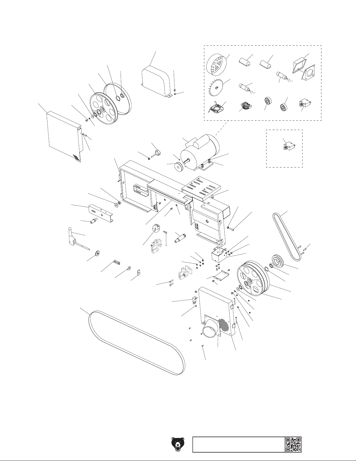
Saw Head
2056
2053
2947
2051
2951
2944
2052
2067
2047
2040
2950
2950
2066
2049
2044
2932
2946
2930
2041
2050
2045
2048
2941
2060
2055
2949
2061
2058
2936
2937
2063
2936
2057
2938
2042
2935
2942
2935
2950
2935
2945
2062
2936
2057-1
2057-2
2057-8
2057-9
2941
2940
2939
2934
2057-3
2057-4
2057-10
2948
2935
2936
2064
2951
2950
2947
2943
2057-5
2057-6
2057-11
2057-12
2057-12X
(for 220V
conversion)
2059
2045
2930
2044
2043
2057-7
2931
2046
Model G0960 (Mfd. Since 09/22)
2068
2065
2942
BUY PARTS ONLINE AT GRIZZLY.COM !
Scan QR code to visit our Par ts Store.
2054
-65-

Saw Head Parts List
REF PART # DES CRIPTI ON REF P ART # DESCRIPTI ON
2040 P09602040 WHEEL (LEFT) 2059 P09602059 V-BELT A33
2041 P09602041 BODY 2060 P09602060 BLADE COVER
2042 P09602042 WHEEL S HAFT (RI GHT) 2061 P09602061 KNOB BOLT 5/16-18 X 2, 12-LOBE, D40
2043 P09602043 WHEEL ( RI G HT) 2062 P09602062 DUST PORT COVER (SQUARE)
2044 P09602044 TIRE ( RUBBE R) 2063 P09602063 B RUSH
2045 P09602045 BALL BEARING 6003ZZ 2064 P09602064 DUST PORT (SQ UARE)
2046 P09602046 WHEEL PULLEY 2065 P09602065 DUST PORT 4 "
2047 P09602047 SAW BLADE 84-7/16 X 3/4 X 0.025 X 3 TPI 2066 P09602066 TENSION LEVER
2048 P09602048 TENSI ON NUT 3/ 8-16 2067 P09602067 FLAT WASHER 10 X 40 X 5
2049 P09602049 COMPRESSION SPRING 5 X 24 X 50 2068 P09602068 HINGE PIN
2050 P09602050 BLADE TENSION POINTER 2930 P09602930 I NT RETAI NI NG RI NG 35MM
2051 P09602051 WHEEL BRACKET (LEFT) 2931 P09602931 CAP SCREW M6-1 X 20
2052 P09602052 WHEEL SHAFT (LEFT) 2932 P09602932 CAP SCREW 1/4-20 X 3/8
2053 P09602053 WHEEL DOOR (LEFT) 2934 P09602934 HEX NUT M8-1. 25
2054 P09602054 WHEEL DO OR (RI GHT) 2935 P09602935 FLAT WASHER 1/4
2055 P09602055 WHEEL DOOR LOCK KNOB 2936 P09602936 HEX BOLT M6-1 X 10
2056 P09602056 PULLEY COVER 2937 P09602937 SHOULDER SCREW M6-1 X 5, 7 X 362
2057 P09602057 MOTOR 2HP 110V 1-PH 2938 P09602938 SET SCREW 1/4-20 X 3/8
2057-1 P09602057-1 MOTOR FAN CO VER 2939 P09602939 CARRIAGE BOLT 5/16-18 X 1
2057-2 P09602057-2 MOTOR FAN 2940 P09602940 FLAT WASHER 5/16
2057-3 P09602057-3 R CAPACITOR COVER 2941 P09602941 HEX NUT 5/16-18
2057-4 P09602057-4 R CAPACITOR 50M 250V 1-9/16 X 2-3/4 2942 P09602942 BUTTON HD CAP SCR M5 -. 8 X 1 0
2057-5 P09602057-5 S CAPACITOR COVER 2943 P09602943 HEX NUT M5-. 8
2057-6 P09602057-6 S CAPACITOR 400M 125V 1-3/4 X 3-3/8 2944 P09602944 FLAT WASHER 1/2
2057-7 P09602057-7 JUNCTI ON BO X 2945 P09602945 HEX NUT 1/4-20
2057-8 P09602057-8 CONTACT PLATE 27 X 69 INT, CPT 6MM 2946 P09602946 LOCK NUT 1/2-12
2057-9 P09602057-9 CENTRI FUG AL S WI TCH 3 / 4 1720 2947 P09602947 HEX BOLT 1/4-20 X 1/2
2057-10 P09602057-10 BALL BEARING 6205-2RS (FRONT) 2948 P09602948 CAP SCREW M8-1.25 X 25
2057-11 P09602057-11 BALL BEARING 6203-2RS (REAR) 2949 P09602949 CARRIAGE BOLT 1/4-20 X 1-1/4
2057-12 P09602057-12 CIRCUIT BREAKER KUOYUH 98 20A 110V 2950 P09602950 LOCK WASHER 1/4
2057-12X P09602057-12X CIRCUIT BREAKER KUOYUH 88 10A 220V 2951 P09602951 FLAT WASHER 1/4
2058 P09602058 MOTOR PULLEY
-66-
BUY PARTS ONLINE AT GRIZZLY.COM !
Scan QR code to visit our Par ts Store.
Model G0960 (Mfd. Since 09/22)
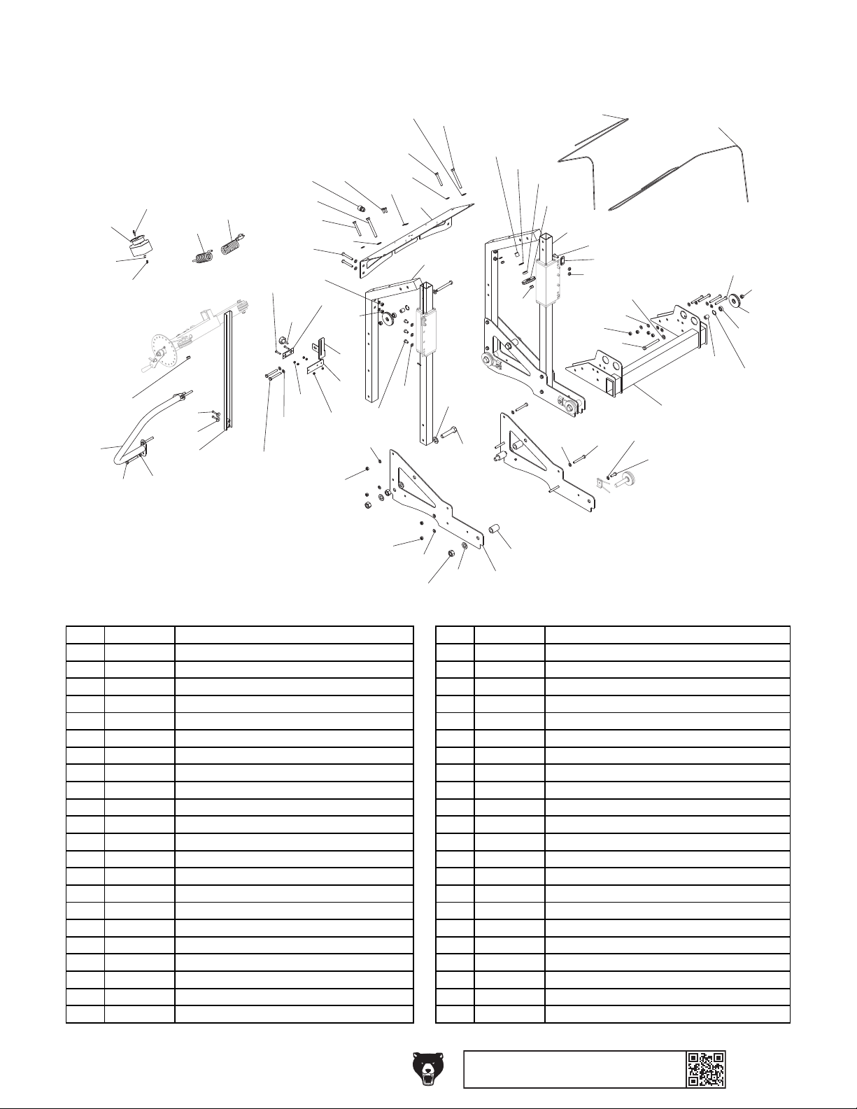
Carriage
3910
3021
3907
REF PART # DES CRIPTI ON REF PART # DES CRIPTION
3925
3017
3019
3908
3906
3924
3926
3916
3951
3011
3905
3027
3026
3916
3906
3025
3914
3906
3915
3015
3917
3905
3905
3904
3919
3907
3016
3904
3012
3013
3917
3912
3905
3915
3905
3918
3905
3009
3006
3914
3909
3911
3020
3902
3908
3008
3007
3905
3001
3904
3927
3028
3962
3905
3914
3906
3907
3905
3022
3906
3908
3007
3008
3023
3902
3005
3921
3904
3905
3909
3001 P09603001 FRONT PO ST 3902 P09603902 I NT RE TAI NI NG RI NG 28MM
3002 P09603002 CARRIAGE LEG SLIDE PLATE 3904 P09603904 HE X NUT M10 -1. 5
3003 P09603003 SPACER 3905 P09603905 FLAT WASHER 3/8
3005 P09603005 CROSS BEAM 3906 P09603906 HEX BOLT M10-1.5 X 80
3006 P09603006 REAR POST 3907 P09603907 FLAT WASHER 1/2
3007 P09603007 CABLE PULLEY 3908 P09603908 HEX NUT M12-1.75
3008 P09603008 BALL BEARING 6001-2RS 3909 P09603909 FLAT WASHER 3/4
3009 P09603009 SWI TCH PANE L 3910 P09603910 HEX NUT M20- 2. 5
3011 P09603011 SCALE 3911 P09603911 HEX BOLT M20-2.5 X 90
3012 P09603012 SCALE CALIBRATION BRACKET 3912 P09603912 HEX BOLT M10-1.5 X 16
3013 P09603013 SCALE BACKING BRACKET 3914 P09603914 HEX BOLT M12-1.75 X 110
3015 P09603015 KNOB BOLT 5/16-18 X 5/8, 12-LOBE, D39 3915 P09603915 HEX BOLT M10-1.5 X 70
3016 P09603016 SCALE INDICATOR 3916 P09603916 HEX BOLT M6-1 X 30
3017 P09603017 PUSH HA NDLE 3917 P09603917 HEX NUT M6 -1
3019 P09603019 ON/OFF SWITCH JP-9501-1A/1B 3918 P09603918 FLAT WASHER 5/16
3020 P09603020 SPACER 12 X 19 X 19.5 3919 P09603919 HEX BOLT M8-1.25 X 20
3021 P09603021 LIFT CABLE A 77" 3921 P09603921 HEX BOLT M10-1.5 X 30
3022 P09603022 LIFT CABLE B 106" 3924 P09603924 BUTTON HD CAP SCR M4-. 7 X 20
3023 P09603023 SPACER 12 X 19 X 23 3925 P09603925 FLAT WASHER #10
3025 P09603025 STRAIN RELIEF TYPE-3 PG13.5 3926 P09603926 HEX NUT M4 -. 7
3026 P09603026 POWER CORD 14G 3W 70" 5-15P 3927 P09603927 HEX BOLT M10-1.5 X 25
3027 P09603027 MOTOR CORD 14G 3W 45" 3951 P09603951 FLAT WASHER 1/4
3028 P09603028 PLATE 3962 P09603962 LOCK NUT M10-1.5
3003
3002
Model G0960 (Mfd. Since 09/22)
BUY PARTS ONLINE AT GRIZZLY.COM !
Scan QR code to visit our Par ts Store.
-67-

Carriage Leg Roller & Post Sleeve
4980
REF PART # DES CRIPTI ON REF PART # DES CRIPTION
4112
4113
4112
4981
4111
4982
4983
4950
4110
4119
4118
4110 P09604110 TRACK ROLLER 4119 P09604119 LOCKING PLATE
4111 P09604111 BALL BEARING 6004-2RS 4950 P09604950 LOCK WASHER 1/4
4112 P09604112 WHEEL SWEEP BRACKET 4980 P09604980 HEX BOLT M20-2.5 X 90
4113 P09604113 SWEEP CABLE 250MM 4981 P09604981 FLAT WASHER 3/4
4117 P09604117 POST SLEEVE 4982 P09604982 I NT RE TAI NI NG RI NG 42MM
4118 P09604118 SPACER (NYLON) 4983 P09604983 HEX BOLT M6-1 X 20
4117
-68-
BUY PARTS ONLINE AT GRIZZLY.COM !
Scan QR code to visit our Par ts Store.
Model G0960 (Mfd. Since 09/22)

5099
5973
5972
REF PART # DES CRIPTI ON REF PART # DES CRIPTION
5093
Lift Assembly
5007
5094
5970
5093
5972
5908
5092
5095
5974
5008
5902
5927
5962
5091
5097
5908
5972
5098
5007
5902
5970
5008
5007
5090
5935
5971
5972
5100
5096
5007 P09605007 CABLE PULLEY 5100 P09605100 I NDEX PLUNGER
5008 P09605008 BALL BEARING 6001-2RS 5902 P09605902 I NT RE TAI NI NG RI NG 28MM
5090 P09605090 LI FT HOUSI NG 5908 P09605908 HEX NUT M12-1.75
5091 P09605091 LIFT EXTENSION ARM 5927 P09605927 HEX BOLT M10-1.5 X 25
5092 P09605092 THRUST BEARING 51202 5935 P09605935 FLAT WASHER 1/4
5093 P09605093 SPACER 5962 P09605962 LOCK NUT M10-1.5
5908
5094 P09605094 LI FT SHAFT 5970 P09605970 FLAT WASHER 1/2
5095 P09605095 LI FT HANDWHEE L 5971 P09605971 BUTTON HD CAP SCR M6-1 X 16
5096 P09605096 CRANK 5972 P09605972 FLAT WASHER 1/2
5097 P09605097 CABLE HOOK 5973 P09605973 HEX BOLT M12-1.75 X 80
5098 P09605098 SPACER 5974 P09605974 KEY 5 X 5 X 15 RE
5099 P09605099 FIXED HANDLE 22 X 80, M10-1.5 X 14
Model G0960 (Mfd. Since 09/22)
BUY PARTS ONLINE AT GRIZZLY.COM !
Scan QR code to visit our Par ts Store.
-69-

Blade Guides
6007
6010
REF PART # DES CRIPTI ON REF PART # DES CRIPTION
6007
6008
6007
6023
6016
6015
6023
6005
6015
6004
6023
6006
6003
6004
6023
6002
6015
6023
6004
6016
6004
6023
6004
6003
6023
6010
6002
6023
6023
6015
6023
6004
6002 P09606002 GUIDE ASSEMBLY SHAFT 6008 P09606008 BALL BEARING 6001-2RS
6003 P09606003 DOVETAIL BLOCK 6010 P09606010 BASE
6004 P09606004 SET SCREW 1/4-20 X 1/4 6015 P09606015 GUIDE BLOCK
6005 P09606005 BEARING SLIDING BLOCK 6016 P09606016 CERAMIC GUIDE
6006 P09606006 BEARING SHAFT 6023 P09606023 SET SCREW 1/4-20 X 1/2
6007 P09606007 EXT RE TAI NI NG RI NG 10MM
6006
6007
6008
6005
-70 -
BUY PARTS ONLINE AT GRIZZLY.COM !
Scan QR code to visit our Par ts Store.
Model G0960 (Mfd. Since 09/22)

Labels & Cosmetics (Front)
grizzly.com
REF PART # DES CRIPTI ON REF PART # DES CRIPTION
7006
MODEL G0960
Specifications
Motor: 2 HP, 110V/220V, 1-Ph, 60 Hz
Prewired Voltage: 110V
Full-Load Current Rating at 110V: 14A
Full-Load Current Rating at 220V: 7A
Maximum Log Length: 43-5/16"
Min/Max Log Diameter: 4"−13"
Maximum Width of Cut: 13"
Maximum Depth of Cut: 6-1/2"
Minimum Height Above Bed: 9/16"
Blade: 84-7/16" x 3/4" x 0.025"
Blade Speed: 2900 FPM
Weight: 430 lbs.
To reduce risk of serious personal injury when using this machine:
1. Read and understand owner’s manual before operating.
2. Never touch moving blade and always keep hands out of blade path.
3. Always wear approved eye protection and a respirator.
4. Only plug power cord into a grounded outlet.
5. Only remove lumber and scrap from track bed when blade is stopped.
6. Always turn motor OFF and disconnect power before changing blades, making
adjustments, or servicing.
7. Maintain proper adjustment of blade tension, tracking, and guides.
8. Secure workpiece firmly to track bed with log supports and clamps while cutting.
9. Only run machine with wheel covers closed and all guards in place.
10. DO NOT wear loose clothing, gloves, jewelry, or other articles that can get
entangled. Tie back long hair and roll up sleeves.
11. DO NOT expose to rain or use in wet locations.
12. DO NOT operate under influence of drugs or alcohol, or if tired.
13. Prevent unauthorized use by children or untrained users; restrict access or
disable machine when unattended.
MINI SAWMILL PRO
Date
S/N
Mfd. for Grizzly in Taiwan
WARNING!
7005
7007
7001
To reduce risk of death
or serious injury, read
manual BEFORE using
machine.
To get a new manual, call
(800) 523-4777 or go to
www.grizzly.com.
Disconnect power
before adjustments,
maintenance, or
service.
Tie back long hair, roll up
long sleeves, and remove
loose clothing, jewelry, or
gloves to prevent getting
caught in moving parts.
WARNING!
Always wear safety
glasses and a
respirator when
using this machine.
7003
WARNING!
INJURY/SHOCK
HAZARD!
WARNING!
ENTANGLEMENT
HAZARD!
EYE/LUNG INJURY
HAZARD!
0
1
2
3
4
5
6
7
8
9
10
11
12
13
14
15
INCH
7002
0
1
2
3
4
5
6
7
8
9
10
11
12
13
14
15
16
17
18
19
20
21
22
23
24
25
26
27
28
29
30
31
32
33
34
35
36
37
38
CM
7001 P09607001 GRIZZLY.COM LABEL 7005 P09607005 ELECTRICITY LABEL
7002 P09607002 SCALE LABEL 7006 P09607006 MACHINE ID LABEL
7003 P09607003 COMBO WARNING LABEL 7007 P09607007 TOUCH-UP PAI NT, GRI ZZLY B EI GE
7004 P09607004 HEIGHT UP/DOWN LABEL
Model G0960 (Mfd. Since 09/22)
BUY PARTS ONLINE AT GRIZZLY.COM !
Scan QR code to visit our Par ts Store.
W
O
D
O
N
E
N
F
U
L
L
EACH NOTCH
EQUALS 0.01"
R
E
U
V
L
O
7004
U
P
"
2
.
0
S
I
N
O
I
T
-71-
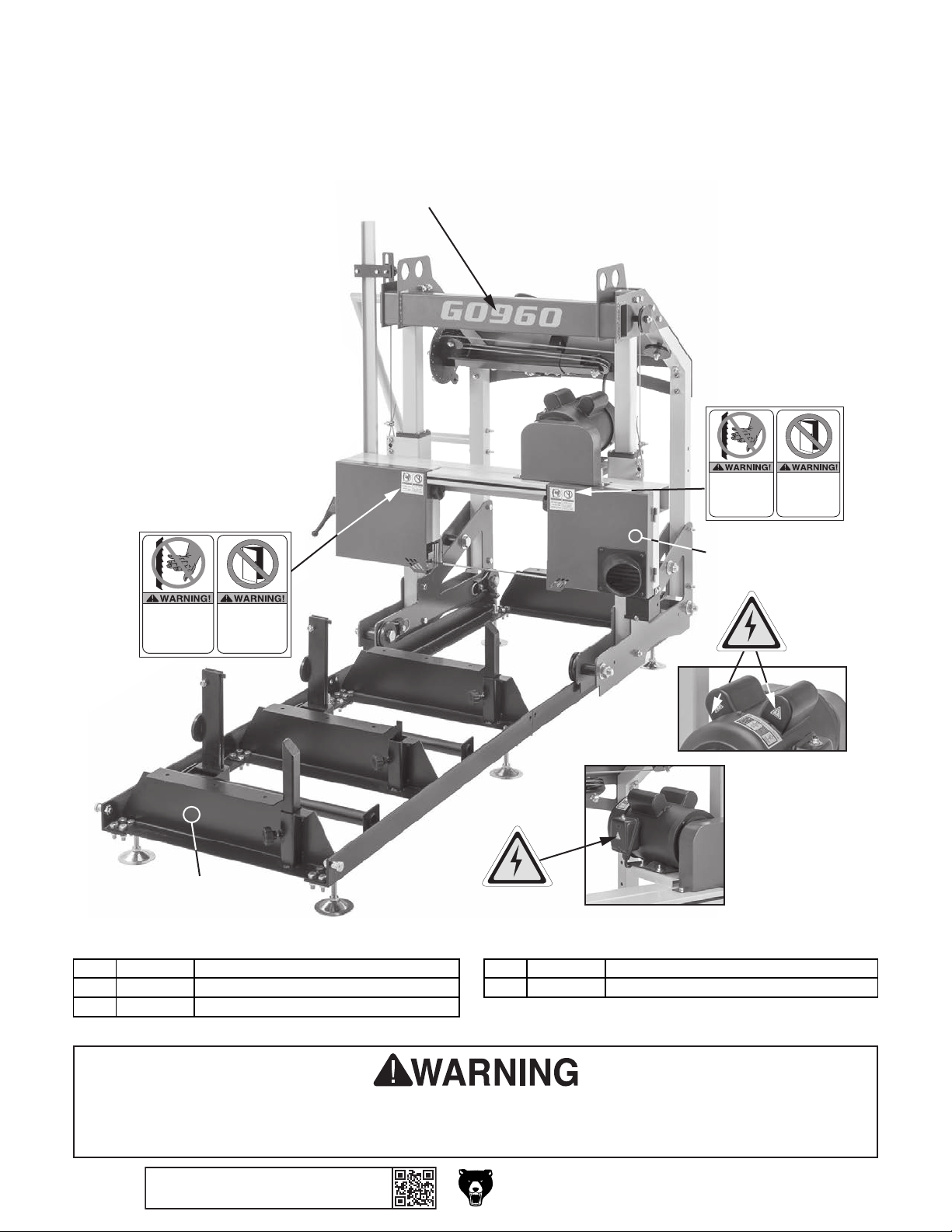
Labels & Cosmetics (Rear)
G0960
7102
REF PART # DES CRIPTI ON REF PART # DES CRIPTION
7103
hands near
7103
Do not open door
while machine is
connected to power
or blade is in motion.
INJURY HAZARD!
DO NOT place
moving blade!
7105
7101
DO NOT place
hands near
moving blade!
7104
7101
INJURY HAZARD!
Do not open door
while machine is
connected to power
or blade is in motion.
7101 P09607101 ELECTRICITY LABEL 7104 P09607104 TOUCH-UP PAINT, G RI ZZL Y GRE EN
7102 P09607102 MODEL NUMBER LABEL 7105 P09607105 TOUCH-UP P AI NT, B LACK
7103 P09607103 BLADE WARNING LABEL
Safety labels help reduce the risk of serious injury caused by machine hazards. If any label comes
off or becomes unreadable, the owner of this machine MUST replace it in the original location
before resuming operations. For replacements, contact (800) 523-4777 or www.grizzly.com.
-72-
BUY PARTS ONLINE AT GRIZZLY.COM !
Scan QR code to visit our Par ts Store.
Model G0960 (Mfd. Since 09/22)

WARRANTY & RETURNS
Grizzly Industrial, Inc. warrants every product it sells for a period of 1 year to the original purchaser from
the date of purchase. This warranty does not apply to defects due directly or indirectly to misuse, abuse,
negligence, accidents, repairs or alterations or lack of maintenance. This is Grizzly’s sole written warranty
and any and all warranties that may be implied by law, including any merchantability or fitness, for any particular purpose, are hereby limited to the duration of this written warranty. We do not warrant or represent
that the merchandise complies with the provisions of any law or acts unless the manufacturer so warrants.
In no event shall Grizzly’s liability under this warranty exceed the purchase price paid for the product and
any legal actions brought against Grizzly shall be tried in the State of Washington, County of Whatcom.
We shall in no event be liable for death, injuries to persons or property or for incidental, contingent, special,
or consequential damages arising from the use of our products.
The manufacturers reserve the right to change specifications at any time because they constantly strive to
achieve better quality equipment. We make every effort to ensure that our products meet high quality and
durability standards and we hope you never need to use this warranty.
In the event you need to use this warranty, contact us by mail or phone and give us all the details. We will
then issue you a “Return Number,’’ which must be clearly posted on the outside as well as the inside of
the carton. We will not accept any item back without this number. Proof of purchase must accompany the
merchandise.
Please feel free to write or call us if you have any questions about the machine or the manual.
Thank you again for your business and continued support. We hope to serve you again soon.
To
you can
applicable information for
take advantage of this warranty, you must register it at https://www.grizzly.com/forms/warranty, or
scan the QR code below to be automatically directed to our warranty registration page. Enter all
the product.
WARRANTY

 Loading...