

Page 1

CS Espresso Machine
CS1-110, CS1-220, CS2-220, CS3-220
Operator Manual
Grindmaster-Cecilware
4003 Collins Lane, Louisville, KY 40245 USA
Phone: 502.425.4776 Toll Free: 800.695.4500
Fax: 502.425.4664
Web: gmcw.com Email: info@gmcw.com
Safety Information..................2
Specifications...........................3
Overview..................................4
Installation...............................6
Programming ..........................6
Operation ................................7
Cleaning...................................8
Adjustments ..........................10
Draining.................................11
Troubleshooting....................11
Parts Diagram........................12
Wiring Diagram.....................26
Thank you for purchasing this quality espresso machine. For your safety and the safety of others, read all warnings
and the operator manual before installing or using the product. Properly instruct all operators. Keep training
records. For future reference, record serial number here:
Table of Contents
©2018 Grindmaster-Cecilware
Printed in Taiwan
0318 Form # CW-345-02
Part # 390-00119
Grindmaster-Cecilware provides the
industry’s BEST warranty. Visit gmcw.com
for warranty terms and conditions.
Model CS2-220
Activate your warranty now at
http://gmcw.com/warranty-registration
Page 2

GB Series Cecilware
®
2
For safe and proper operation the appliance must be placed in a stable, vertical position.
To reduce risk of serious burns or scalding, do not place hand or other body parts under dispenser while product
is brewing.
Always unplug unit from power supply before servicing.
Surfaces are hot and can cause burns. Use caution especially in the areas of the steam wand, hot water wand,
and brewing group.
Packaging material, including plastic bag and Styrofoam, can be dangerous and should be kept out of reach of
children.
To reduce risk of electrical shock, do not touch machine with wet hands or feet.
CAUTION
To reduce risk of electrical shock, do not remove or open cover. No user-serviceable parts inside. Repair should
be done by authorized service personnel only.
The appliance is not intended for outdoor use. Do not expose to rain or direct sunlight.
Do not clean with pressurized water or use in an area where pressurized water may be used.
Cleaning and maintenance shall be made only by properly trained persons with supervision.
This appliance is not intended for use by persons with reduced physical, sensory, or mental capabilities, or lack
of experience and knowledge, unless they have been given supervision or instruction concerning use of the
appliance by a person responsible for their safety.
Children should be supervised to ensure that they do not play with the appliance.
Do not alter or deform the power cord or plug in any way! Altering or deforming the plug may cause electrical
shock, damage unit, and will void warranty.
To reduce risk of explosion or fire, do not use near combustibles.
WARNING
Safety Information
2 Grindmaster
®
CS Espresso Machine
Important Safety Information
This is the safety alert symbol. It is used to alert you to potential personal injury hazards. Obey all safety messages
that follow this symbol to avoid possible injury or death.
For your safety and the safety of others, read all warnings and the operator manual before installing or using
the product.
DANGER: This term warns the user of imminent hazard that will result in serious injury or death.
WARNING: This term refers to a potential hazard or unsafe practice, which could result in serious injury or death.
CAUTION: This term refers to a potential hazard or unsafe practice, which could result in minor or moderate
injury.
NOTICE: This term refers to information that needs special attention or must be fully understood.
Observe machine voltage configuration. Do not apply improper voltage to machine or damage to machine may
occur. For use on individual dedicated branch circuit only. Do not use extension cord.
Follow national and local electrical codes.
Do not use the machine and turn off the power during water outage.
This equipment must be installed in compliance with applicable Federal, State, and/or Local plumbing codes
having jurisdiction. This product requires an approved back flow prevention water device, such as a double
check valve, to be installed between the machine and the water supply.
Please follow maintenance and cleaning instructions specified in this manual to ensure the best operation
efficiency of machine.
NOTICE
Page 3

CS Espresso Machine Grindmaster
®®
3
Rough-In Drawing
24.8”
(63 cm)
20.5”
(52 cm)
37.4”
(95.0 cm)
27.8”
(70.5 cm)
18.9”
(48 cm)
Specifications
Identification Label
Every machine has an identification label placed on the front of the machine as illustrated below. The label
includes information of model number, voltage, serial number, wattage, and its certificate. Do not remove this
label.
Figure A
Figure B
Page 4

4 Grindmaster
®
CS Espresso Machine
Specifications (continued)
Specification Table
Overview
CS1
CS2
Figure C
Figure D
Model Number of Heads Boiler Capacity Electrical
CS1-110 1 Group 6 quarts / 6 L 110/120V / 1Ph / 50/60 Hz / 18 A / 2 kW
CS1-220 1 Group 6 quarts / 6 L 220/240V / 1Ph / 50/60 Hz / 10 A / 2000 W
CS2-220 2 Groups 13 quarts / 6 L 220/240V / 1Ph / 50/60 Hz / 20 A / 4700 W
CS3-220 3 Groups 19 quarts / 18 L 220/240V / 1Ph / 50/60 Hz / 27 A / 6500 W
Side Clearance required - 4" (10.2 cm)
Rear Clearance required - 4" (10.2 cm) for water and electrical connections
Water connection size - 3/4" GHT, 1/2" water line required
Water pressure between 20 PSI and 120 PSI (138 kPa - 827 kPa). Use regulator if higher pressure.
Page 5

CS Espresso Machine Grindmaster
®®
5
Overview continued
CS3
Control Panel
Figure E
Figure F
Figure G
1 Espresso brewing unit control panel 11 Cup rack
4 Hot water wand 12 Sight glass (Boiler level check window)
5 Steam knob 14 Steam boilder pressure gauge
6 Steam wand 15 Pump pressure gauge
7 Main switch 17 Drain tray
8 Brewing group 18 Leg
9 Porta Filter 20 Hot water knob
Small single portion
Small double portion
Large single portion
Large double portion
Continuous Flow Button
Page 6

6 Grindmaster
®
CS Espresso Machine
Unpacking Instructions
Carefully unpack the machine and inspect immediately
for shipping damage. The packaging may contain
unattached parts. Your machine was shipped in a carton
designed to give it maximum protection in normal
handling. It was thoroughly inspected before leaving
the factory. In case of damage, contact the shipper, not
Grindmaster-Cecilware.
NOTICE:
This equipment must be installed in
compliance with applicable Federal, State, and/or Local
plumbing codes having jurisdiction. This product requires
an approved back flow prevention water device, such as
a double check valve, to be installed between the
appliance and the water supply. If a check valve type
backflow preventer is used for water supply protection,
a screen of at least 100 mesh (100 strands per 1.0 in [25
mm]) shall be installed immediately upstream. The screen
shall be accessible and removable for cleaning or
replacement. (Required for NSF approved water hookup.)
Incoming pressure should be greater than 20 psi and not
more than 90 psi.
• A filtering system is recommended to remove odors
and inhibit lime and scale build up in the unit.
• In areas with extremely hard water, a water softener
must be installed in order to prevent a malfunctioning
of the equipment and in order not to void the warranty.
Unsoftened water will decompose dissolvable minerals
and turn to limescale after boiling. The limescale will
reduce the machine’s thermal efficiency and machine’s
lifetime.
NOTICE: Do not use extension cords. Make sure that the
outlet the unit plugs into is grounded.
Check rating
marking on nameplate to be sure electric lines match
voltage, phase, and amperage requirements of
appliance.
Connections
1. When operating the machine for the first time or
replacing water softener and filtration system,
remove the water inlet tube and allow it to drain
for about one minute in order to get rid of
impurities from the water.
2. Connect a 1/2" diameter water line to the water
supply connection.
3. Open the water shut-off valve and check
connections for leaks. DO NOT over-tighten. Verify
water supply.
4. Connect 18mm diameter drain line to bottom,
center of machine.
5. Attach appropriate plug to cord. Power source
corresponds to the electrical rating shown on the
serial tag on unit. Plug the CS Espresso machine into
a dedicated power supply outlet.
6. Activate the Power Switch on front of unit (see
Figure H). The tank will fill in approximately 3-4
minutes.
7. Press continuous flow button on each control panel
(right button) to verify water flow.
8. After installing the machine, verify that during
water intake the steam boiler pressure gauge
indicator is within the green zone (1~1.4bar) and
the pump pressure gauge indicator, when using the
continuous flow button, is also within the green
zone (8~10bar). In case of need to adjust the
pressure, refer to Adjustments section.
Programming
Control Panel
There are two identical control panels on two-cup
models and three identical control panels on 3-cup
models. No default coffee output setting is provided.
Settings must be made manually during set-up. If you
are using a multi-cup machine, settings made on the
farthest right hand side control panel will serve as the
default for the others. Therefore, to set different values
for different cup compartments, begin set up from the
right and work your way to the left, to prevent the
previous setting from being overwritten.
WARNING: ELECTRIC SHOCK HAZARD!
Installation of this appliance should be performed by
qualified service personnel only. Improper installation
could result in electrocution.
CAUTION: BURN HAZARD
Steam wand, hot water wand, and brewing unit are
very hot. Use caution when operating unit to prevent
burns.
Figure H
CAUTION: BURN HAZARD
Unit is very hot. Use caution when turning on
programming switch to prevent burns.
Installation
Page 7

CS Espresso Machine Grindmaster
®®
7
1. Turn on the programming switch. (see Figure I)
2. The LED of buttons 1 - 4 on the control panel will
be lit, and the fifth LED will flicker. This indicates
programming mode for setting up the amount of
continuous output. (See Figure J)
3. Place measuring cup under the brewing group.
Hold down the first button until reaching the
required amount of water. Do not otherwise touch
the panel. Meanwhile the first button’s light will be
off, the other three buttons still lit, and the fifth
button flickers (see Figure K). It means the first
button is programmed. Continue programming
other buttons. Turn programming switch to OFF
when completed. Each time the programming
switch is turned ON, it will reset the buttons.
NOTICE: To avoid overheating, electric wires should
be kept untangled and free of obstructions. Don’t block
air intake or outlet vents on the machine. Never cover
or otherwise prevent the free flow of air across the cup
warmer.
NOTICE: Do not use cleansers, bleach liquids, powders
or any other substance containing chlorine. These
products promote corrosion and will pit the stainless
steel. USE OF THESE PRODUCTS WILL VOID THE
WARRANTY.
1. Place an appropriate quantity of ground coffee in
the Porta Filter and tamp the ground coffee firmly.
Clean all residual coffee from the rim and sides of
the filter. This is to ensure a good seal and full
pressure when brewing coffee, and prolong the
lifetime of the gasket. Attach the Porta Filter to the
machine by rotating until it locks in place.
2. Place cup(s) or glass(es) under spout(s).
3. Either press desired portion button or press and
hold the continuous flow button until desired
portion is dispensed. To stop flow at any time, press
and release continuous flow button. (See Figure L)
4. Move cup(s) or glass(es) to side and remove Porta
Filter. Dump grinds. Carefully hold Porta Filter near
group head and rinse using the continuous flow
button water. Use extreme caution to avoid burns.
Then, fit empty Porta Filter to the brewing group
to store and keep warm.
Steam Wand:
This can be used by turning the knob counterclockwise,
which allows for a varied amount of steam or by pulling
out the handle which will dispense the maximum
amount of steam.
Programming (continued) Operation
CAUTION: BURN HAZARD
Steam wand, hot water wand, and brewing unit are
very hot. Use caution when operating unit to prevent
burns.
Figure I
Figure J
Figure K
Figure L
Page 8

8 Grindmaster
®
CS Espresso Machine
Steam Wand (continued)
1. To drain condensate, ensure steam wand is pointed
toward the drain grid and pull handle out briefly to
dispense a small amount of steam.
2. Pour cold milk in a pitcher and place steam arm into
pitcher. Hold pitcher with one hand and turn on
steam, either by twisting to add a controlled
amount or pulling knob out to add steam at full
pressure.
3. Remove pitcher.
4. Wipe arm and nipple clean with soft cloth
moistened with sanitizer solution after each use.
After wiping, pull steam knob to release a steam
burst through the tube to remove any residual milk
remaining in the nozzle.
NOTICE: Remove the pitcher from the steam tube
after foaming milk. Failure to do so may draw liquid
from the pitcher into the steam tube, risking machine
component contamination.
Hot Water
1. Turn the hot water knob counterclockwise to obtain
hot water through hot water wand. Hot water
output will increase the further the hot water knob
is turned. Turn the knob clockwise to reduce/stop
hot water output.
2. You can also pull the knob straight out in order to
obtain hot water.
Cleaning
NOTICE: All sanitizing agents in the food zone must
comply with 21 CFR 178.1010. Sanitize all food
dispensing units periodically. All parts to be sanitized
must be cleaned first. Cleaning and sanitizing frequency
must follow state and local health department
regulations.
NOTICE: Wipe the accessories with a soft cloth or
specific detergent powder. Don’t use scrub sponge or
wire brushes.
After each brewing
1. Carefully hold Porta Filter near group head and
rinse Porta Filter using the continuous flow button
water. Water is hot - use extreme caution.
2. Wipe arm and nipple clean with soft cloth
moistened with sanitizer solution after each use.
After wiping, pull steam knob to release a steam
burst through the tube to remove any residual milk
remaining in the nozzle.
Daily
Exterior:
Wipe the machine exterior with soft, slight
dampened cloth daily before starting operations. If
necessary, a mild, non-corrosive cleaning agent may
be applied to the cloth.
NOTICE: Do not spray cleaning fluid directly on the
espresso machine to avoid corrosion or possible
electrical damage.
Back flushing:
1. Remove screw (E), shower screen (D), and plate (C)
from the group head (be careful, metal components
may be hot). (see Figure M)
2. Place the rubber disc in Porta Filter (see Figure N),
and apply about 2-3 grams of espresso machine
detergent/sanitizer on top of rubber disc. Attach
the Porta Filter to the group head and check for
tightness.
3. Press first and fifth buttons simultaneously to start
automatic back flushing function. The first and fifth
button will be off, and middle three buttons will be
lit. This auto back flushing system will complete 10
cleaning cycles. (see Figure O)
NOTE: If you want to discontinue the cleaning, press 3rd
button to stop.
Figure M
Operation (continued)
CAUTION: BURN HAZARD
Steam wand, hot water wand, and brewing unit are
very hot. Use caution when operating unit to prevent
burns.
Figure N
Page 9

CS Espresso Machine Grindmaster
®®
9
Cleaning (continued)
4. After automatic back flushing cycle is complete,
rinse Porta Filter and rubber disc with water from
the continuous flow button until water in Porta
Filter appears clean.
5. Replace rubber disc on Porta Filter, then place Porta
Filter on the group head and press first and fifth
buttons simultaneously to start automatic back
flushing function to rinse. The first and fifth button
will be off, and middle three buttons will be lit. This
auto back flushing system will complete 10 cleaning
cycles.
NOTE: If you want to discontinue the cleaning, press 3rd
button to stop.
6. Screw (E), shower screen (D), and plate (C) should
be cleaned and sanitized with the Porta Filter, steam
wand nipple and hot water wand sprayer.
Cleaning and sanitizing portafilter:
Notice: To avoid damage, do not immerse espresso
Porta Filter handle in water. Do not put group gasket
(item B from Figure M) in water or any liquid
detergent.
1. Disassemble Porta Filter. (see Figure P)
2. Remove sprayer from hot water wand.
3. Remove nipple from steam arm.
4. Add loose group head parts [screw (E), shower
screen (D), and plate(C) from Figure M].
5. Use brush to clean and wash parts in detergent or
espresso urn cleaner/sanitiser. DO NOT immerse
Porta Filter handle. (see Figure Q)
6. Rinse parts.
7. Prepare a sanitizing solution in accordance with
local health department regulations. You may also
refer to the US Food and Drug Administration
regulation 21 CFR 178.1010 “Sanitizing Solutions”
and US Environmental Protection Agency 40 CFR
18.940 “Tolerance exemptions for active and inert
ingredients for use in antimicrobial formulations
(Food-contact surface sanitizing solutions)”.
8. Follow the instructions provided with the sanitizing
agent.
9. Let all sanitized parts drain and dry naturally. DO
NOT WIPE THEM DRY.
10. Reassemble parts.
Drain Tray and Discharge Trough:
1. Remove and wash the drain tray after stopping use.
(see Figure R)
2. Wipe and remove sediments in the discharge
trough with a wet cloth and wash with hot water
to clear the discharge tube.
3. If water does not discharge properly, place a
Figure O
Figure P
CAUTION: BURN HAZARD
Steam wand, hot water wand, and brewing unit are
very hot. Use caution when cleaning unit to prevent
burns.
Handle
Do not immerse
Liquid
Figure Q
Figure R
Page 10

10 Grindmaster
®
CS Espresso Machine
Cleaning (continued)
teaspoon of detergent into the discharge trough
and flush with hot water to dissolve residual oils in
the tube.
4. Reassemble after the water tray has dried.
Adjustments
NOTICE: Please contact your authorized service
representative to undertake these procedures.
The rest of this manual contains information to aid the
service technician who is maintaining this equipment.
This section has information on performing common
service tasks.
Pump Pressure Adjustment
The pump pressure has been factory adjusted to 9 bar
(the recommended pressure). After machine starts up
and water refills, press continuous flow button and read
pressure on pressure gauge if the indicator is on green
zone (8-10 bar) as shown in Figure S.
If the pressure is not in the green zone, adjust pressure
as shown below:
1. Remove left side panel
2. Attach Porta Filter into the brewing group with
filled ground coffee.
3. Press continuous flow button. Turn screw clockwise
as shown in Figure T to increase pressure; turn
counterclockwise to reduce pressure.
Steam Boiler Pressure Calibration
Steam boiler pressure is controlled by pressure switch.
The pressure inside the boiler continues to rise as the
water is heated by the heating elements. Reducing
pressure will reduce temperature, while increasing
pressure will increase temperature. The steam boiler has
been factory adjusted to 1.2bar, (the recommended
pressure). Please check if your pressure on the pressure
switch is 1.2bar or on the green zone (1-1.4bar) (see
Figure U). if so, you don’t need to adjust the pressure.
In case there is a need to calibrate the pressure, please
follow below procedure for calibration:
NOTE: Please turn off the machine before undertaking
this operation.
1. Turn off machine.
2. Remove top cover of machine, and locate the
pressure switch on the upper right size.
3. Remove the yellow case from the pressure switch.
Use screw to adjust the pressure as shown in Figure
V. Turn screw clockwise to decrease pressure, or
counterclockwise to increase pressure. A complete
screw turn results in 0.1 bar variation.
Figure S
Figure T
Figure U
Figure V
WARNING: SHOCK HAZARD
Disconnect power before adjusting steam boiler
pressure.
CAUTION: BURN HAZARD
Steam wand, hot water wand, and brewing unit are
very hot. Use caution when adjusting unit to prevent
burns.
Page 11

CS Espresso Machine Grindmaster
®®
11
If espresso machine will not be used for an extended
period, will be stored, or transported, drain tank to
prolong life and prevent damage from freezing.
1. Turn off the machine, and release all the pressure
from boiler by turning on the steam knob(s).
2. After the steam is completely released and the
pressure on steam boiler pressure gauge reads “0”,
remove drain tray and locate drain valve under
drain tray. Turn on drain valve to drain water out of
boiler. Drain valve is on when it is parallel to pipe.
NOTE: Please DO NOT turn off the steam knob after the
steam is released for storage. Keep the steam knob on.
When you re-start the machine, do not turn off the
steam knob until you see water drop from the steam
wand. This is to balance the boiler pressure.
3. Turn off drain valve when water stops flowing into
waste cup. Drain valve is off when it is
perpendicular to pipe.
CAUTION: BURN HAZARD
Dispenser surfaces and water inside dispenser are very
hot. Use caution when draining unit to prevent burns.
CAUTION: BURN HAZARD
Never turn on drain valve when there is pressure in
the boiler.
Troubleshooting
Before you call for help, please read the following:
WARNING: To reduce the risk of electrical shock, unplug the dispenser power cord before repairing or
replacing any internal components of the unit. Before any attempt to replace a component, be sure to check all
electrical connections for proper contact. Only a qualified service technician should perform electrical and
mechanical adjustments or repairs.
Note: Wait at least 3 seconds to restart the machine after turning it off to ensure previous error stored in memory
is cleared.
If you need help, call Grindmaster-Cecilware Technical Service Department, (502) 425-4776 or (800) 695-4500 (USA
& Canada only) (Monday through Friday 8 AM - 6 PM EST). Please have the model and serial number ready so
that accurate information can be given.
Prior authorization must be obtained from Grindmaster-Cecilware for all warranty claims.
Grindmaster-Cecilware provides the industry’s BEST warranty. Visit our website at gmcw.com for
warranty terms and conditions.
INDICATION PROBABLE CAUSE SOLUTION
All lights on control •
Aer two minutes of •Water level probe not
•
Make sure that the water
panel turn on water input, indicator
funconing properly.
valve is turned on and
still does not show a there is water flowing
rise in machine water into machine.
level. It will take more •
Water intake solenoid is
• Turn off machine. Restart
than two minutes to
out of order.
after 3 seconds.
replenish water when •
Input water flow has been
• Turn water supply on.
the machine is used
interrupted.
for the first time.
All lights on ONE • No water output • Coffee grounds are too • Adjust fineness of coffee
control panel flash from brewing group. fine. grinds.
• Brewing for a long • Water intake solenoid is • Turn off machine. Restart
time without reaching out of order. after 3 seconds.
setup value. • Flow meter is out of order. • Press any key to eliminate
the breakdown signal,
and notify qualified service
technician.
Draining
Page 12
12 Grindmaster
®
CS Espresso Machine
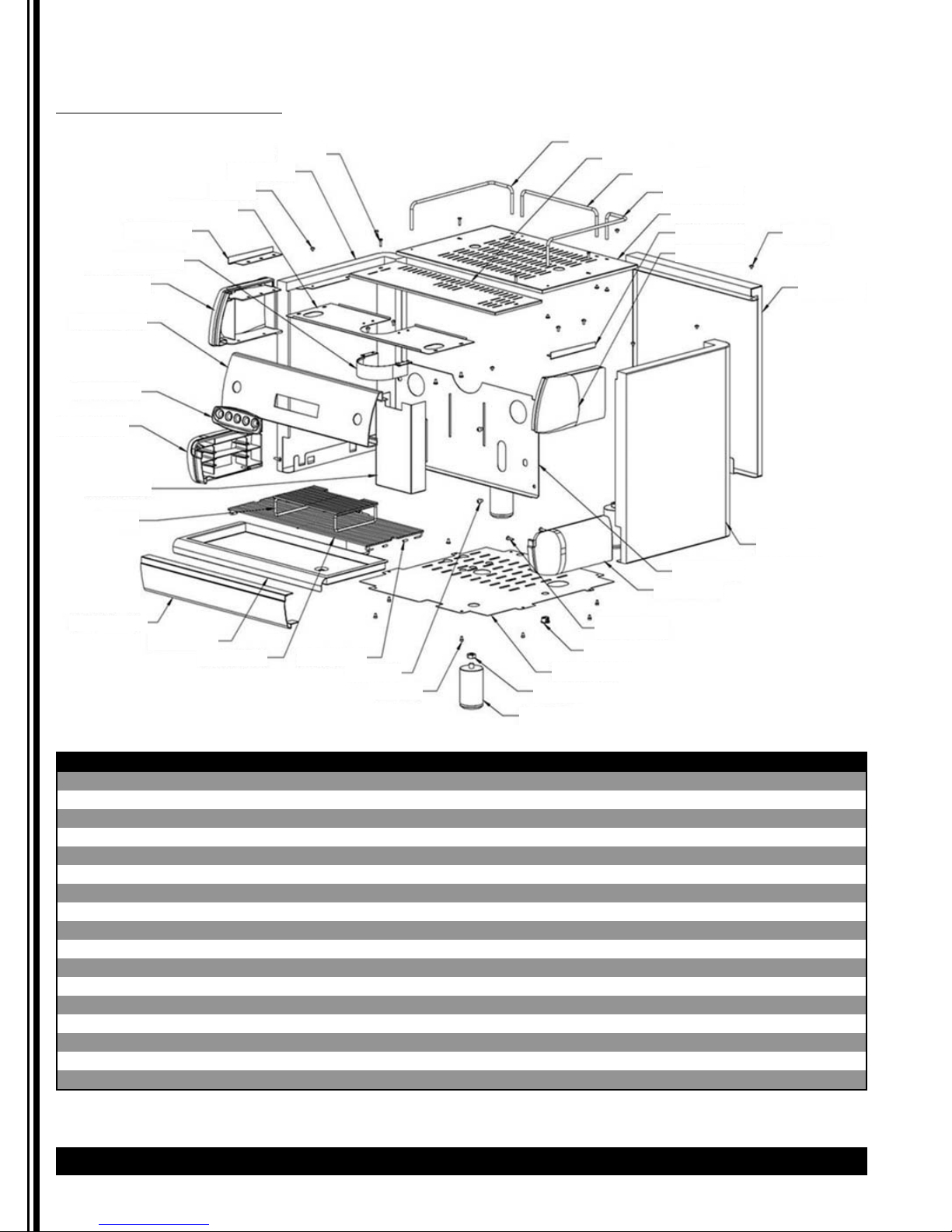
Parts Diagram
Body Parts CS1-110, CS1-220
Item Part # Descripon Item Part # Descripon
1 SCREW M4*16 18 SCREW M4*5 (SUS)
2 LEFT SIDE PANEL(BLACK) 19 410-00482 FOOT
3 SCREW M4*5 20 NUT M10
4 CABLE COVER 21 BOTTOM METAL COVER (ETL)
5 TOP RIGHT SIDE PANEL SUPPORT 22 CABLE PROTECTION RING (ETL)
6 SURROUND STEEL 23 SCREW ( 4mm*15 )
7 TOP LEFT SIDE PANEL 24 DOWN RIGHT SIDE PANEL
8 BASE FRONT PANEL 25 S.STEEL BOILER COVER
9 410-00483 OPERATE FACEPLATE 26 RIGHT SIDE PANEL (BLACK)
10 DOWN LEFT SIDE PANEL 27 BACK PANEL(BLACK)
11 VALVE COVER 28 TOP RIGHT SIDE PANEL
12 410-00484 CUP RACK 29 TOP LEFT SIDE PANEL SUPPORT
13 BASE FRONT PANEL 30 UPPER STAINLESS STEEL GRILL
14 410-00485 DRAIN PAN 31 CUP FENCE-RIGHT
15 410-00486 LOWER DRAIN PAN 32 CUP FENCE -REAR
16 DRAIN TUBE 5/8" HIGH TEMP 33 GROUP COVER
17 SCREW M6*8 34 CUP FENCE-LEFT
1
2
3
4
5
6
7
8
9
10
11
12
13
14
15
16
17
18
26
25
24
23
22
21
20
19
34
33
32
31
30
29
28
3
27
Page 13
CS Espresso Machine Grindmaster
®®
13
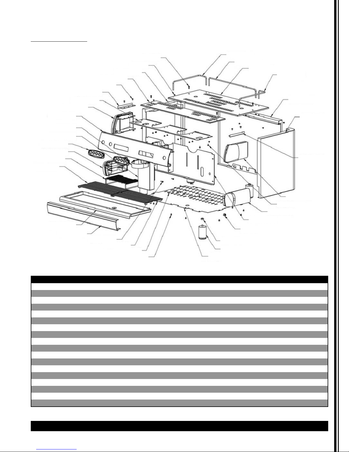
Parts Diagram (continued)
Body Parts CS2-220
Item Part # Descripon Item Part # Descripon
1 SCREW M4*16 19 DRAIN TUBE 5/8" HIGH TEMP
2 SCREW M4*5 20 SCREW M6*8
3 LEFT SIDE PANEL(BLACK) 21 SCREW M4*6
4 GROUP COVER 22 BOTTOM METAL COVER (ETL)
5 SCREW M4*8 (SUS) 23 410-00482 FOOT
6 TOP RIGHT SIDE PANEL SUPPORT 24 NUT M10
7 CABLE COVER 25 CABLE PROTECTION RING (ETL)
8 TOP LEFT SIDE PANEL 26 S.STEEL BOILER COVER
9 OPERATION PANEL 27 DOWN RIGHT SIDE PANEL
10 SURROUND STEEL 28 TOP RIGHT SIDE PANEL
11 VALVE COVER 29 TOP LEFT SIDE PANEL SUPPORT
12 410-00483 OPERATE FACEPLATE 30 RIGHT SIDE PANEL (BLACK)
13 DOWN LEFT SIDE PANEL 31 BACK PANEL(BLACK)
14 410-00484 CUP RACK 32 CUP FENCE-RIGHT
15 410-00488 LOWER DRAIN PAN 33 UPPER STAINLESS STEEL GRILL
16 410-00487 DRAIN PAN 34 CUP FENCE-REAR
17 BASE SURROUND FRONT 35 CUP FENCE-LEFT
18 SCREW ( 4mm*15 )
1
35
2
3
4
5
6
7
8
9
10
11
12
13
14
15
16
17
18
19
20
21
34
33
32
31
30
29
28
5
27
26
25
24
23
22
Page 14
14 Grindmaster
®
CS Espresso Machine
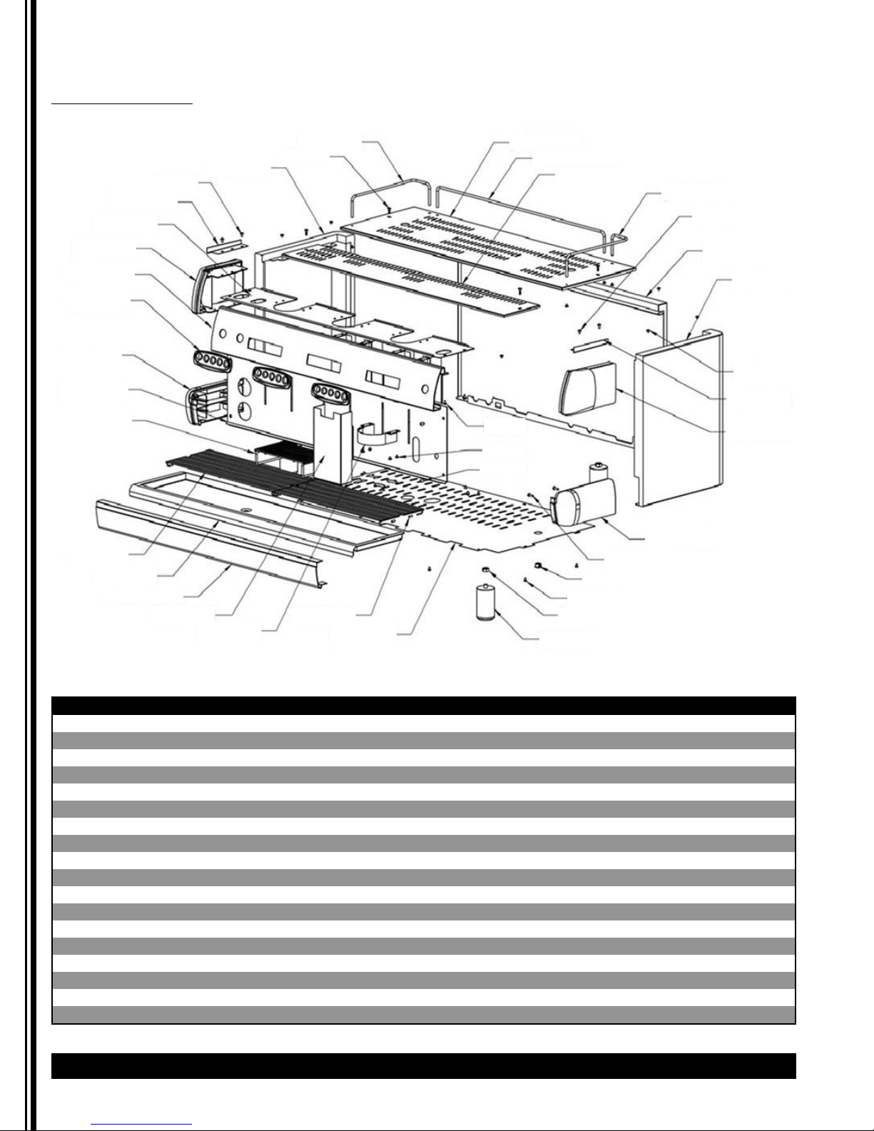
Parts Diagram (continued)
Body Parts CS3-220
Item Part # Descripon Item Part # Descripon
1 CUP FENCE-LEFT 19 BOTTOM METAL COVER (ETL)
2 SCREW M4*16 20 410-00482 FOOT
3 LEFT SIDE PANEL(BLACK) 21 NUT M10
4 SCREW M4*8 (SUS) 22 SCREW M4*6
5 TOP RIGHT SIDE PANEL SUPPORT 23 CABLE PROTECTION RING (ETL)
6 CABLE COVER 24 SCREW ( 4mm*15 )
7 TOP LEFT SIDE PANEL 25 DOWN RIGHT SIDE PANEL
8 OPERATION PANEL 26 SCREW M6*8
9 410-00483 OPERATE FACEPLATE 27 SCREW M4*5
10 DOWN LEFT SIDE PANEL 29 TOP RIGHT SIDE PANEL
11 S.STEEL BOILER COVER 30 TOP LEFT SIDE PANEL SUPPORT
12 410-00484 CUP RACK 30 RIGHT SIDE PANEL (BLACK)
13 410-00490 LOWER DRAIN PAN 31 BACK PANEL(BLACK)
14 410-00489 DRAIN PAN 32 CUP FENCE-RIGHT
15 BASE SURROUND FRONT 33 GROUP COVER
16 VALVE COVER 34 CUP FENCE-REAR
17 SURROUND STEEL 35 UPPER STAINLESS STEEL GRILL
18 DRAIN TUBE 5/8" HIGH TEMP
1
35
2
3
4
5
6
7
8
9
10
11
12
13
14
15
16
17
18
19
34
33
32
4
31
30
27
29
28
25
24
23
22
21
20
4
27
26
Page 15
CS Espresso Machine Grindmaster
®®
15
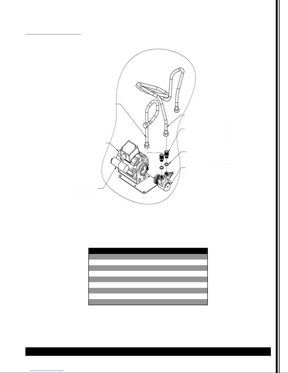
Parts Diagram (continued)
Motor Pump Assembly
Item Part # Descripon
1 S.T. STEEL WIRE PIPE (600mm)
2 01329L MOTOR 220-240V 50/60Hz 1.6A (ETL)
3 410-00491 CAPACITOR 10μF
4 01330L PUMP FOR CS1-220
4 PUMP FOR CS2 & CS3
4 PUMP FOR CS1-110
5 01312L PIPE GASKET TEFLON
6 NPT FITTING NPT3/8"*NPT1/2"
7 S.T. STEEL WIRE PIPE (2400mm)
1
7
6
5
4
2
3
Page 16

16 Grindmaster
®
CS Espresso Machine
Parts Diagram (continued)
Boiler Hydraulic Circuit CS1
Item Part # Descripon Item Part # Descripon
1 01320L LEVEL PROBE ASSEMBLY 27 WATER LEVEL LOWER TUBE
2 01319L ANTI-EDDY VALVE V.A.R. 28 01318L SI-GASKET ELEMENT
3 01322L VALVE GASKET BRASS 29 01316L HEATING ELEMENT 2000W�CE�
4 01371L SAFETY VALVE 29 410-00494 HEATING ELEMENT 1500W�110V)
5 HEAT EXCHANGER OUTLET TUBE 30 410-00495 HEX SCREW (M10*16)
6 WATER LEVEL UPPER TUBE 31 ELBOW BRASS 5/16*1/4
7 HEAT EXCHANGER RETURN TUBE 32 BRASS PLUG
8 STEAM PRESSURE GAUGE TUBE 33 AUT.WATER REFILL TUBE REAR
9 BRASS CONNECTOR 1/2-20UNF*PT1/4 34 PRESSURE GAUGE COPPER TUBE
10 HOT WATER OUTLET TUBE REAR 35 STEAM OUTLET TUBE FRONT RIGHT
11 BOILER 36 01321L VALVE GASKET BRASS
12 AUT.WATER REFILL TUBE 37 BRASS CONNECTOR 1/4"X1/8"
13 HEAT EXCHANGER INLET TUBE 38 01324L SOL. VALVE WATER REFILL ASSY 208~240V 60Hz
14 BRASS FITTING PS/1/4*PS1/4*L33.5 39 BRASS CONNECTOR PT1/4*1/2-20UNF*1/2-20UNF
15 BRASS FITTING PS/1/4*PS1/4*L42 40 BRASS CONNECTOR
16 01325L FLOWMETER DOSER 41 SPHERICAL BRONZE CONICAL FILTER
17 FLOW METER GAUGE 42 01323L NBR O RING
18 ELBOW BRASS PT3/8*3/8 43 LEVEL PROBE BASE
19 FLOWMETER INLET TUBE 44 410-00502 PROBE FIXED SUPPORT
20 410-00492 S.C.N.R.DOSER VALVE 1/2*1/2*1/2 45 PROBE FIXED BOLT
21 BOILER DRAIN TUBE FRONT 46 410-00504 PROBE ( SUS304 /3mm L132 )
22 EXPANSION DRAIN TUBE 47 410-00496 BRASS NUT
23 NUT M8 48 410-00497 TEFLON WASHER
24 SPRING WASHER M8 49 410-00498 SI O-RING
25 410-00493 PRESSURE RELEASE TAP BULK PS1/4xPS1/4 50 410-00499 SHAFT
26 BOILER DRAINTUBE REAR 51 410-00500 ANTI-EDDY VALVE BASE
1
42
2
3
4
5
6
7
8
9
10
11
12
13
14
15
16
17
19
20
18
21
22
40
39
38
37
36
35
34
33
32
31
30
29
28
27
26
25
24
23
31
43
44
45
46
1
47
48
49
50
51
2
41
Page 17

CS Espresso Machine Grindmaster
®®
17
Parts Diagram (continued)
Boiler Hydraulic Circuit CS2
Item Part # Descripon Item Part # Descripon
1 01321L VALVE GASKET BRASS 28 WATER LEVEL LOWER TUBE
2 01319L ANTI-EDDY VALVE V.A.R. 29 01318L SI-GASKET ELEMENT
3 01322L VALVE GASKET BRASS 30 01315L HEATING ELEMENT 4000W (CE)
4 HEAT EXCHANGER OUTLET TUBE LEFT 31 410-00495 HEX SCREW (M10*16)
5 HOT WATER CONDUCT TUBE IN BOILER 32 AUT.WATER REFILL TUBE REAR
6 STEAM OUTLET TUBE FRONT RIGHT 33 WATER LEVEL UPPER TUBE
7 HOT WATER OUTLET TUBE REAR 34 PRESSURE GAUGE COPPER TUBE
8 STEAM OUTLET TUBE FRONT LEFT 35
BRASS CONNCTR PT1/4*1/2-20UNF*1/2-
9 BOILER 36 BRASS CONNECTOR 1/4"X1/8"
10 AUT.WATER REFILL TUBE 37 01324L
SOL. VALVE WATER REFILL ASSY 208~240V 60Hz
11 HEAT EXCHANGER RETURN TUBE LEFT 38 BRASS CONNECTOR
12 HEAT EXCHANGER RETURN TUBE RIGHT 39 SPHERICAL BRONZE CONICAL FILTER
13 ELBOW BRASS PT3/8*3/8 40 01323L NBR O RING
14 BRASS FITTING PS/1/4*PS1/4*L33.5 41 HEAT EXCHANGER OUTLET TUBE RIGHT
15 BRASS FITTING PS/1/4*PS1/4*L42 42 01371L SAFETY VALVE
16 01325L FLOWMETER DOSER 43 01320L LEVEL PROBE ASSEMBLY
17 FLOW METER GAUGE 44 410-00496 BRASS NUT
18 EXPANSION DRAIN TUBE 45 410-00497 TEFLON WASHER
19 410-00492 S.C.N.R.DOSER VALVE 1/2*1/2*1/2 46 410-00498 SI O-RING
20 FLOWMETER INLET TUBE 47 410-00499 SHAFT
21 HEAT EXCHANGER INLET TUBE 48 410-00500 ANTI-EDDY VALVE BASE
22 BOILER DRAIN TUBE FRONT 49 410-00504 PROBE ( SUS304 /3mm L132 )
23 410-00493
PRESSURE RELEASE TAP BULK UNIT PS1/4xPS1/4
50 PROBE FIXED BOLT
24 BOILER DRAINTUBE REAR 51 410-00502 PROBE FIXED SUPPORT
25 ELBOW BRASS 5/16*1/4 52 LEVEL PROBE BASE
26 NUT M8 53 BRASS CONNECTOR 1/2-20UNF*PT1/4
27 SPRING WASHER M8
1
43
2
3
4
5
6
7
8
9
10
11
12
13
14
15
16
17
18
19
20
21
42
3
41
40
39
38
37
36
35
34
33
32
44
45
46
47
48
2
31
30
29
28
27
26
25
24
43
49
50
51
52
23
22
53
Page 18

18 Grindmaster
®
CS Espresso Machine
Parts Diagram (continued)
Boiler Hydraulic Circuit CS3
1
48
6
50
2
49
3
4
5
7
8
9
10
11
12
13
14
15
16
17
18
19
22
23
24
25
26
27
20
21
47
46
45
44
43
42
33
41
40
39
38
28
29
30
31
32
33
34
37
36
35
55
56
57
58
59
44
51
52
53
54
47
Page 19

CS Espresso Machine Grindmaster
®®
19
Parts Diagram (continued)
Boiler Hydraulic Circuit CS3
Item Part # Descripon Item Part # Descripon
2 GROUP FILTER ST.STEEL D13.8*d10.5*11.5 32 SPRING WASHER M8
3 01323L NBR O RING 33 ELBOW BRASS 5/16*1/4
4 AUT. WATER REFILL REDUCTION 34 WATER LEVEL LOWER TUBE
6 HOT WATER OUTLET TUBE REAR 35 410-00495 HEX SCREW (M10*16)
7 SHAFT 36 01317L HEATING ELEMENT 6000W (CE)
8 BRASS CONNECTOR 37 01318L SI-GASKET ELEMENT
9 STEAM OUTLET TUBE FRONT LEFT 38 AUT.WATER REFILL TUBE REAR
10 01322L VALVE GASKET BRASS 39
WATER LEVEL UPPER TUBE
11 HOT WATER CONDUCT TUBE IN BOILER 40 BOILER
12 STEAM PRESSURE GAUGE TUBE 41
HEAT EXCHANGER OUTLET TUBE RIGHT
13 HEAT EXCHANGER RETURN TUBE MIDDLE 43 HEAT EXCHANGER OUTLET TUBE MIDDLE
14 HEAT EXCHANGER RETURN TUBE RIGHT 44 01319L ANTI-EDDY VALVE V.A.R.
15 AUT.WATER REFILL TUBE MIDDLE 45 HEAT EXCHANGER OUTLET TUBE LEFT
16 BRASS FITTING PS/1/4*PS1/4*L33.5 46 01321L VALVE GASKET BRASS
17 BRASS FITTING PS/1/4*PS1/4*L42 47 01320L LEVEL PROBE ASSEMBLY
18 01325L FLOWMETER DOSER 48 01371L SAFETY VALVE
19 FLOW METER GAUGE 49 BRASS CONNECTOR 1/4"X1/8"
20 ELBOW BRASS PT3/8*3/8 50 01324L
SOL. VALVE WATER REFILL ASSY 208~240V 60Hz
21 HEAT EXCHANGER INLET TUBE LEFT 51 LEVEL PROBE BASE
22 EXPANSION DRAIN TUBE 52 410-00502 PROBE FIXED SUPPORT
23 410-00492 S.C.N.R.DOSER VALVE 1/2*1/2*1/2 53 PROBE FIXED BOLT
24 BOILER DRAIN TUBE FRONT 54 410-00504 PROBE ( SUS304 /3mm L132 )
25 410-00493
PRESSURE RELEASE TAP BULK UNIT PS1/4xPS1/4
55 410-00496 BRASS NUT
26 HEAT EXCHANGER INLET TUBE MIDDLE 56 410-00497 TEFLON WASHER
27 FLOWMETER INLET TUBE 57 410-00498 SI O-RING
28 HEAT EXCHANGER RETURN TUBE LEFT 58 410-00499
BRASS CONNECTOR PT1/4*1/2-20UNF*1/2-20UNF
29 HEAT EXCHANGER INLET TUBE RIGHT 59 410-00500 ANTI-EDDY VALVE BASE
30 BOILER DRAINTUBE REAR WATER REFILL SET
31 NUT M8 STEAM OUTLET TUBE FRONT RIGHT
Page 20
20 Grindmaster
®
CS Espresso Machine
Parts Diagram (continued)
Water Level Assembly
1
8
2
3
4
5
6
7
2
1
8
13
12
11
10
4
3
9
Item Part # Descripon
1 01375L HEX SCREW (M8*10)
2 01305L
SIGHT GLASS RUBBER GASKET�10.69*ψ 3.5�
3 01306L COPPER SEAL
4 01372L BRASS NUT
5 01373L LEVEL-INDICATING BALL
6 01307L SIGHT GLASS
7 PC PANNEL
8 01374L WASHER (M8*3t)
9 01376L LAVEL CONNECTOR (LOWER)
11 WATER LEVEL ASSEMBLY
12 SIGHT GLASS REAR COVER
13 01370L LEVEL CONNECTOR (UPPER)
LEVEL LABEL
Page 21

CS Espresso Machine Grindmaster
®®
21
Parts Diagram (continued)
Distribution Group Assembly
Item Part # Descripon Item Part # Descripon
1 DISTRIBUTION GROUP CAP 14 410-00506 HEX SCREW M4*12
2 TEFLON GASKET D22*d18*2.0 15 01381L GROUP JET D0.8
3 01382L GROUP FILTER ST.STEEL D13.8*d10.5*11.5 15 01301L
PAEKER GROUP SOLENOID VALVE COIL 208~240V
5 STAINLESS STEEL SCREW M5*10 15 410-00507
PAEKER GROUP SOLENOID VALVE COIL 110V
6 DISTRIBUTION GROUP BODY 16 410-00508 DISTRIBUTION GROUP ASSEMBLY
7 01304A SI_O-RING d47*3.5t 17 BRASS PLUG
8 CHROMED CLAMPING RING 18 WATER INLET CONNECTOR
9 01300L FILTER GROUP GASKET 19 410-00510 GROUP WASHER
10 410-00501 GROUP PLATE 20 PT1/4x5/8-18UNF L_FITTING
11 410-00503 GROUP SHOWER SCREEN 21 WATER RECYCLE CONNECTOR
12 01302L STAINLESS STEEL FLATHEAD SCREW M5*15 22 410-00509 DISTRIBUTION GROUP ASSEMBLY
13 410-00505 PRESSURE RELEASE DRAIN TUBE
1
18
2
3
4
5
6
5
7
8
9
10
11
12
19
18
17
17
16
15
14
13
13
14
15
17
19
17
22
20
21
1
2
3
4
5
6
5
7
8
9
10
11
12
CS1-110, CS1-220
CS2-220, CS3-220
Page 22

22 Grindmaster
®
CS Espresso Machine
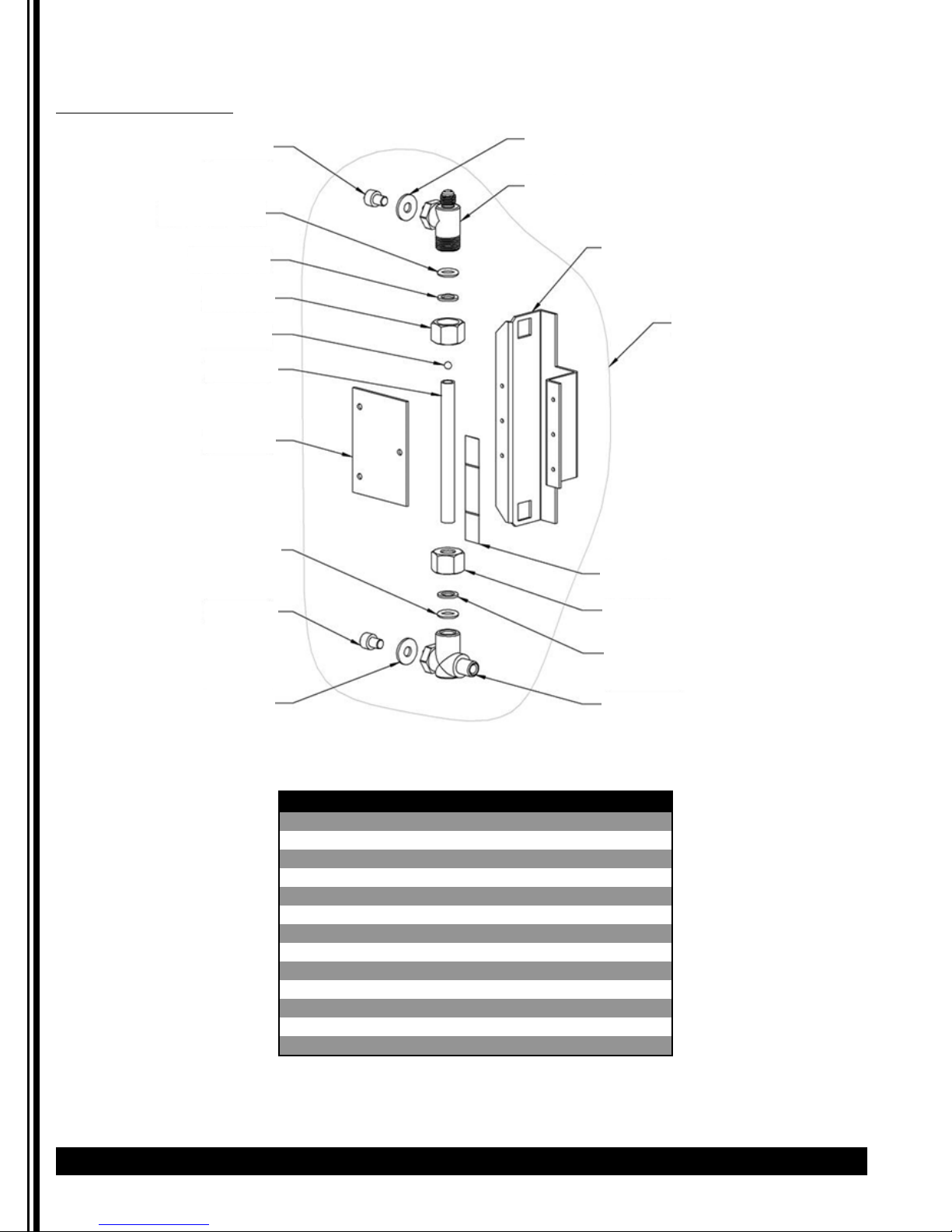
Parts Diagram (continued)
Water and Steam Assembly
Item Part # Descripon Item Part # Descripon
1 410-00511 TAP BODY 19 EXTERNAL SPRAYER
2 BRASS NUT 20 SILICON GASKET
3 410-00512 WATER/STEAM TAP UNIT 21 HOT WATER SPRINKLE-NOZZLE (UPPER)
4 01336L AS�KNOB 23 HOT WATER TUBE KIT
5 01311L R STEEL CIRCLIP 24 NUT PIPE STEAM FOR SPRING
6 01337L WATER STEAM TAP ASSEMBLY 25 01312L PIPE GASKET TEFLON
7 01333L STEAM KNOB CAP 26 STEAM TAP SPRING
8 01332L HOT WATER KNOB CAP 27 01379L STEAM TAP WASHER
9 01308L SI-GASKET 28 01313L O-RING
10 STEAM HOT WATER A VALVE SHAFT 29 410-00513 KIT HOT WATER TUBE
11 01310L COPPER SEAL 31 EXTERNAL SPRAYER
12 STEAM TAP SPRING 32 410-00514 STEAM TUBE
13 TAP CONNECTOR 33 410-00515 STEAM TUBE KIT
14 01335L CHROMED TAP SHAFT 34 410-00516 ANTISCORCHING CLIP
15 WASHER (SUS 304) 35 O-RING
17 TIGHTING GASKET 36 STEAM SPRAYER
18 HOT WATER SPRINKLE-NOZZLE (UNDER)
6
13
5
17
16
3
15
22
21
20
19
18
14
12
11
10
9
3
2
1
4
23
24
25
26
31
30
29
28
27
36
32
24
28
27
26
25
33
34
7
8
35
Page 23

CS Espresso Machine Grindmaster
®®
23
Parts Diagram (continued)
Portafilter Assembly
Item Part # Descripon
1 01356 2 CUP STAINLESS STEEL FILTER
2 01352 FILTER CLAMP SPRING D1.4
3 01350 FILTER SUPPORT
4 01358 2 CUP BRASS SPOUT
5 01355 2 CUP PORTA FILTER ASSEMBLY
6 01346 FILTER HOLDER KNOB CAP
7 01354 FILTER HOLDER BACK LID
8 01348 1 CUP STAINLESS STEEL FILTER
9 01351 1 CUP BRASS SPOUT
10 01347 1 CUP PORTA FILTER ASSEMBLY
11 01346 SILICA GEL WASHER
4
5
3
2
1
6
7
8
2
3
9
10
6
11
Page 24

24 Grindmaster
®
CS Espresso Machine
Parts Diagram (continued)
Electrical System Assembly
2
1
4
5
6
8
9
10
11
12
13
3
14
27
26
25
23
22
24
21
20
19
18
9
17
16
15
7
Item Part # Descripon Item Part # Descripon
1 LEVEL PROBE CABLE 15 FLOWMETER GAUGE CABLE FOR CS2
2 RADIATOR (ETL) 15 FLOWMETER GAUGE CABLE FOR CS3
3 410-00517
SOLID STATE RELAY 25A GN84131011 /CS1
15 FLOWMETER GAUGE CABLE FOR CS1
3 410-00518
SOLID STATE RELAY 50A GN84137021 /CS2 CS3
16 MAIN SWITCH COVER
3 410-00519
SOLID STATE RELAY 25A GN84131011 /N1 110V
17 BAND/CS3
4 410-00520 FAN FOR SSR (ETL) 17 BAND/CS1 CS2
5 SERIES CABLE PCB<->PANEL 18 SCREW ST3.5*19
6 SERIES CABLE PANEL<->PANEL 19
CONTROL BOX WITHOUT IC BOARD (UP COVER)
7 OPERATE BOX 20 SCREW M4*20
8 KEY BOARD FOR COFFEE 21 410-00526 CONTROL PC-MAINBOARD
9 SCREW 3*8 21 410-00527 110V CONTROL PC-MAINBOARD
10 CONTROL PC-MAINBOARD 22 410-00528 CONTROL BOX WITH IC BOARD
11 410-00521
TIMER / TOUCH PAD(CONTROL PC-MAINBOARD)
23
CONTROL BOX WITHOUT IC BOARD (LOWER COVER)
12 MAIN SWITCH HAND GRIP (CE/AU) 24 CABLE UNIT / CS1
13
MAIN SWITCH HAND GRIP LABEL PLATE 0-1 (ETL)
24 CABLE UNIT / CS3
13
MAIN SWITCH HAND GRIP LABEL PLATE 0-1-2 ( CE )
24 CABLE UNIT / CS2
14 410-00522 MAIN SWITCH ASSEMBLY /N1 N2(ETL)(32A) 25 01338L TEMP. PROTECTION FUSE (ETL)
14 410-00523 MAIN SWITCH ASSEMBLY /N3 (ETL)(63A) 26 01326L
SI_501 CE PRESSURE SWITCH 220V AC 7KW 30A
410-00524 MAIN SWITCH ASSEMBLY FOR CS3 27 410-00529 SELECT SWITCH
410-00525 MAIN SWITCH ASSEMBLY FOR CS1 CS2
Page 25

CS Espresso Machine Grindmaster
®®
25
Parts Diagram (continued)
Other Components
Item Part # Descripon
1 SPRING WASHER M8
2 SCREW M8*25
3 410-00530 PRESSURE GAUGE 0 � 20 BAR
4 410-00531 PRESSURE GAUGE 0 ~ 6 BAR
5 ANTI FOOT VIBRATION
6 SPRING WASHER M6
7 NUT M6
8 410-00532 DRAIN BASIN
9 410-00533 SPRING WASHER M10
10 410-00534 NUT M10
1
8
5
2
3
4
6
7
9
10
Page 26

26 Grindmaster
®
CS Espresso Machine
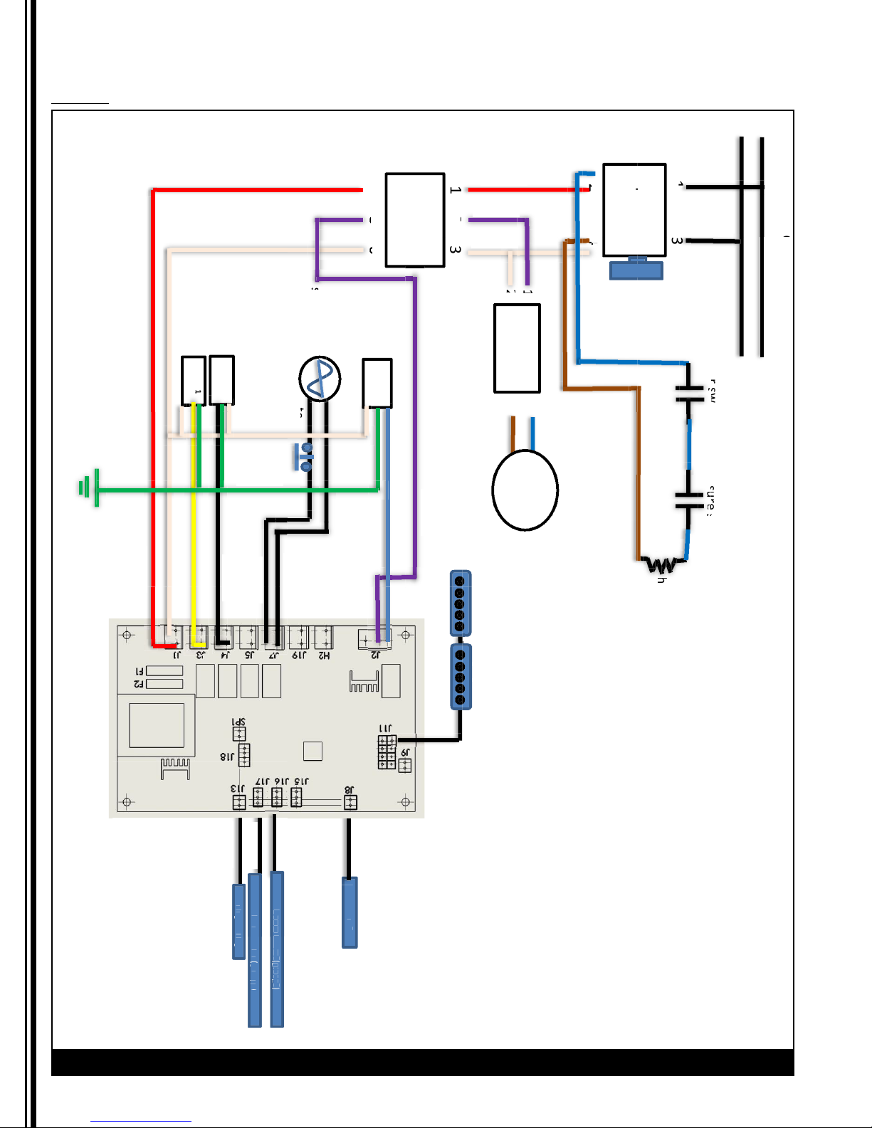
Wiring Diagram
CS1-110
1
%
p
it
w
w
s
s
r
itc
ssr
3
%
s
re
re
u
u
s
h
h
h
s
e
h
c
e
g
g
)
)
puop
g
g
(
g
m
(
t
g
p
2
1
2
1
3
1
lignasssr
tc
t
g
g
Red
White
Blue
Brown
Violet
Yellow
Black
Black
Blue
Brown
Violet
Red
Black
Black
Green
Blue
Black
Black
Black
Black
White
N
L
G
puor
evalv
4
W
erat
evalv
con
cten
o
r
co
roectnn
4
pmpu&
3
rotoM
erwo
hcitsw
reat
Ʋ110
10
H50/60Ɍ 1V
h
srep
itchw
z
1puorg
darobkey
wiring
D
niso
erwoFl
ets
ni
et
1er
r
1
eborperatW
dia
r
am
CV)CS1(110A
Page 27

CS Espresso Machine Grindmaster
®®
27
Wiring Diagram (continued)
CS1-220
%
p
r
e
g
lignasssr
lignasssr
t
Violet
Blue
Black
Black
Yellow
Red
White
Green
White
Red
Violet
White
Blue
Brown
Black
Black
Black
Black
Black
Black
Brown
Blue
am
r
eborperatW
1
uo
r
1er
et
ni
ets
erwoFl
niso
D
CV)CS1(220A
dia
wiring
reat
itchw
srep
darobkey
1puorg
pmpu&
rotoM
tc
z
h
H50/60Ɍ 1V
hcitsw
erwo
10
Ʋ220
L
N
4
3
roectnn
co
erat
W
r
o
cten
con
evalv
4
evalv
puor
G
Page 28
28 Grindmaster
®
CS Espresso Machine
Wiring Diagram (continued)
CS2-220
1
%
p
it
w
w
s
s
r
itc
ssr
3
%
s
re
re
u
u
s
h
h
h
s
e
h
c
e
g
)
)
puop
g
g
(
g
)
)
puop
g
g
(
g
m
(
t
g
m
(
p
2
1
2
1
t
ssr
3
tc
1
m
t
g
g
Black
Black
Black
Black
Black
Black
Black
Black
Black
Black
Yellow
Blue
Brown
White
Red
Violet
Blue
Green
Red
Violet
White
Brown
Blue
puorG
evalv
evalv
G
2puor
N
L
4
con
cten
o
r
lignas
W
erat
evalv
hcitsw
co
roectnn
4
3
rotoM
pmpu&
erwo
Ʋ220
10
H50/60Ɍ 1V
h
srep
itchw
z
2puorg 1puorg
darobkey
reat
wiring
dia
D
Fl
niso
erwo
erwoFl
ets
ni
et
et
2er
1er
r
r
2
1
eborperatW
r
am
CV)CS2(220A
Page 29

CS Espresso Machine Grindmaster
®®
29
Wiring Diagram (continued)
CS3-220
%
p
r
e
g
e
m
m
t
Red
Red
White
Green
Violet
Blue
Black
Orange
Black
Yellow
Black
Brown
Blue
Black
Black
Violet
White
Brown
Blue
Black
Black
Black
Black
Black
Black
Black
am
r
CV)CS3(220A
dia
wiring
reat
itchw
srep
3
uo
r
3er
et
eborperatW
darob
2puorg 1puorg
y
k
3
uo
r
pmpu&
roto
M
erwo
Fl
1
2
uo
uo
r
r
1er
2er
et
et
ni
ets
erwoFl
erwo
niso
Fl
D
z
h
H50/60Ɍ 1V
10
Ʋ220
hcitsw
erwo
L
N
4
3
roectnn
co
r
o
cten
con
erat
W
evalv
4
3puor
evalv
G
lignas
2puor
evalv
puorG
evalv
G
Page 30

30 Grindmaster
®
CS Espresso Machine
Page 31

CS Espresso Machine Grindmaster
®®
31
Page 32

Grindmaster-Cecilware
4003 Collins Lane, Louisville, KY 40245 USA
Phone: 502.425.4776 Toll Free: 800.695.4500
Fax: 502.425.4664
Web: gmcw.com Email: info@gmcw.com
©2018 Grindmaster-Cecilware
Printed in Taiwan
0318 Form # CW-345-02
Part # 390-00119
 Loading...