

Page 1

© Grindmaster Corporation, 2000
PRINTED IN USA
Grindmaster Corporation
4003 Collins Lane
Louisville, KY 40245 USA
(502) 425-4776
(800) 695-4500 USA and Canada only
FAX (502) 425-4664
www.grindmaster.com
0705 Form # WH-302-02
Part # W0600224
Models 3341, 3341A, 3342, 3352
Remote Beverage Freezers Manual
Model 3341
Model 3341A
Model 3342
Model 3352
Page 2

Page 3

Crathco®Remote Beverage Freezers Page 1
Table of Content
s
Introduction . . . . . . . . . . . . . . . . . . . . . . . . . . . . . . . . . . . . . . . . . . . . . . . . . . . . . . . . . . . . . . . . . 2
Freezer Application & Specifications. . . . . . . . . . . . . . . . . . . . . . . . . . . . . . . . . . . . . . . . . . . . . 2
Installation . . . . . . . . . . . . . . . . . . . . . . . . . . . . . . . . . . . . . . . . . . . . . . . . . . . . . . . . . . . . . . . . . . 15
Operation & Adjustments . . . . . . . . . . . . . . . . . . . . . . . . . . . . . . . . . . . . . . . . . . . . . . . . . . . . . . 7
Care and Cleaning . . . . . . . . . . . . . . . . . . . . . . . . . . . . . . . . . . . . . . . . . . . . . . . . . . . . . . . . . . . . 8
Maintenance . . . . . . . . . . . . . . . . . . . . . . . . . . . . . . . . . . . . . . . . . . . . . . . . . . . . . . . . . . . . . . . . 12
Troubleshooting. . . . . . . . . . . . . . . . . . . . . . . . . . . . . . . . . . . . . . . . . . . . . . . . . . . . . . . . . . . . . 15
Key Parts Identification . . . . . . . . . . . . . . . . . . . . . . . . . . . . . . . . . . . . . . . . . . . . . . . . . . . . . . . 16
Assembly & Wiring Diagrams (3341/3341A) . . . . . . . . . . . . . . . . . . . . . . . . . . . . . . . . . . . . . . 17
Assembly & Wiring Diagrams (3342/3352) . . . . . . . . . . . . . . . . . . . . . . . . . . . . . . . . . . . . . . . 26
Autofill Connections Guide . . . . . . . . . . . . . . . . . . . . . . . . . . . . . . . . . . . . . . . . . . . . . . . . . . . 35
Information contained within this manual is subject to change without notice.
Contact Grindmaster Corporation’s Customer/Technical Service Department at 1-800-695-4500 with any questions or for clarification.
Page 4

Page 2 Crathco®Remote Beverage Freezers
OPERATOR’S SAFETY PRECAUTIONS
IMPORTANT: Failure to comply with the following safety precautions may result in severe personal injury or damage
to the machine.
1. Read and understand the operating instructions in this manual thoroughly. Only allow properly trained persons to
operate this machine.
2. Note all warning labels on the freezer. If any warning labels are missing or damaged replace them immediately.
3. Do not wear loose fitting garments or jewelry which could cause a serious accident.
4. Stay alert at all times during operation.
5. Keep operating area clean.
6. Do not attempt any repairs unless the main power supply to the freezer has been disconnected. Contact
Grindmaster Technical Service for service assistance.
7. Do not put objects or fingers in the dispense plunger.
8. Do not operate freezer if any excessive noise or vibration occurs. Contact your authorized service agent.
9. Be certain machine is installed with adequate space for proper air circulation. (See installation section.) Failure
to provide sufficient ventilation will reduce freezer performance and void equipment warranty.
FREEZER APPLICATION AND SPECIFICATIONS
Remote Freezers
The freezer consists of a freezing cylinder with a rotating internal auger (dasher) that is belt-driven by an electric
motor. The auger scrapes frozen product off of the inside of the refrigerated cylinder.
Crathco remote beverage freezers are designed to operate in conjunction with a remote condensing unit or be
connected to a central refrigeration system. It is recommended that the condensing unit have no more than 2 1/2 hp
per barrel to ensure maximum efficiency. The refrigerant must be R404A (Dupont®HP62®). The refrigeration for each
barrel is controlled by the liquid feed solenoid. The liquid feed solenoid is opened and closed by the limit switch
attached to the drive motor. (When the product consistency reaches the desired point, the switch closes and
de-energizes the liquid feed solenoid 20 seconds later.) Twin units operate with each barrel independently. Quick
connect refrigeration connections are supplied with each unit. Each freezer is factory supplied with 5/8" suction and
3/8" liquid connections. The piping connecting the freezer with the remote condensing unit or central system should
be sized according to industry standards. The installer is responsible for sizing the refrigeration lines to the unit.
When properly operated and cared for, the remote freezers will provide many years of service. Proper care includes
regular cleaning and maintenance. To minimize the amount of maintenance necessary, follow the operating procedures outlined in this manual.
There are four variations of the remote unit:
3341 – standard single barrel remote unit
3342 – standard twin barrel remote unit
3341A – single barrel remote unit with internal autofill system
3352 – dual barrel remote unit with internal autofill system
Located on the right, left and rear panels. (part # W0600218)
Page 5

Crathco®Remote Beverage Freezers Page 3
Remote Freezers (cont.)
The autofill system on the 3341A and 3352 models is designed to keep the product hopper full to a predetermined
level. This assembly eliminates the necessity of pre-mixing concentrate and water and the possibility of manual
mixing errors. The mixed product is automatically fed to a Remote Fill Control which is located in the freezer. The
Remote Fill Control then adds pre-mixed product to the freezer mix storage reservoir as required.
When the autofill switch is ON and when the level drops below the probe for 15 seconds, the product feed solenoid
opens. This allows the product from the remote pumping system to fill the hopper. When the liquid level reaches the
probe, the product feed solenoid closes. NOTE: As a safety, the refrigeration liquid feed valve closes until the level in
the freezer reaches the probe. To bypass the automatic feed feature, simply turn the autofill switch to manual. This
allows the refrigeration to operate independently of the autofill and the hopper must be filled manually.
Product Tips
These freezers were designed to dispense a wide variety of frozen beverages including frozen fruit juice, frozen
lemonade, slush and frozen cocktails. These products can be served in consistencies ranging from thin to fairly thick.
Two types of dispensing valve plungers and product consistency springs are available depending on the thickness of
the product being served. These parts are interchangeable depending upon your needs. One plunger, part W0480438
has one horizontal outlet slot and is used to serve thin to medium products such as frozen lemonade and slush. The
other plunger, part W0480451 has two horizontal outlet slots and is used to serve thicker product such as neutral
base frozen cocktails. A red spring, part W0631239, is used on the drive motor to adjust product consistency to serve
thin to medium products. The yellow spring, part W0631238, is used for thicker product. The spring is located next to
the drive motor behind the right hand side panel.
Over an extended period of time, some products, such as frozen cocktails that contain alcohol, have a tendency to
separate, or stratify. Separation of product on the mix storage hopper can result in frozen product quality inconsistency.
Simply keeping the product, in the mix storage hopper, stirred on a regular basis will eliminate this problem.
Some cappuccino or latte mixes contain dairy products which can spoil if not refrigerated. If the freezer is to be
turned off at night these products must
be removed from the freezer.
Contact your local health department regarding its regulations for proper mix handling and storage.
Carburetor Assembly
Your new freezer uses a metering device, known as a carburetor, to feed the proper ratio of mix and air into the
freezing cylinder (and to prevent frozen product from rinsing out of the freezing cylinder). The carburetor, or carb tube,
is a tube with a hole, or series of holes, bored through the side. It is located in the hopper and fits in the hole that
leads to the freezing cylinder. Air flows into the freezing
cylinder through the top of the tube and mix flows in
through a smaller hole in the side of the carb tube. The
size of the mix inlet hole can be balanced with the viscosity
(thickness) of the liquid mix and product draw rate, in such
a way that the proper amount of mix is fed into the freezer
cylinder to blend with air at just the right ratio. Mix viscosity
varies by mix type, mix temperature and mix age. Different
serving rates also demand different feed rates. For many
products, the proper mix to air ratio is generally accepted
to be two parts mix to one part air. This proportion
yields a finished product that is both tasty and profitable. At this ratio, one gallon of liquid mix will yield a
volume of one and one-half gallons of frozen product.
This additional volume is the overrun in the product. Crathco offers three versions of carb tubes (see Figure A).
Depending on the product being served and overrun requirements there is a standard tube for most slush or cocktail
products, a low overrun carb tube that allows all air trapped in the freezing cylinder to escape and a smoothie/shake
carb tube. This carb tube has an outer sleeve that can be rotated to line up with different hole sizes to provide various
levels of overrun. Most applications only require the standard carb tube.
Figure A
Thick product carb tube
(W0471136)
Low overrun
carb tube
(W0472060)
Standard carb tube
(W0471076)
Page 6

Page 4 Crathco®Remote Beverage Freezers
Freezer Specifications
Models 3341/3341A Models 3342/3352
Dimensions
(HxWxD)
26 1/2”H x 13”W x 29”D
67cm x 33cm x 73cm
(includes header box)
26 1/2”H x 18 1/2”W x 29” D
67cm x 47cm x 73cm
(includes header box)
Electrical
115 volt, 60 Hz, 1 Phase
Dedicated 20 Amp circuit
115 volt, 60 Hz, 1 Phase
Dedicated 20 Amp circuit
Drive Motor (1) 1/2 hp (2) 1/2 hp
Compressor Remote condensing unit Remote condensing unit
Cooling N/A N/A
Actual Weight 110 lbs. (49.9 kg) 140 lbs. (63.5 kg)
Mix Hopper Capacity
3341-5 gallons (18.9 liters),
3341A-2.25 gallons (8.55 liters) 3 gallons (11.3 liters)
Freezing Cylinder Capacity 1-1/2 gallons (5.7 liters) 1 1/2 gallons (5.7 liters)
Refrigerant See Serial Number Plate See Serial Number Plate
Refrigerant Charge See Serial Number Plate See Serial Number Plate
High Side
(approximate operating pressure) 120ºF – 130ºF 120ºF – 130ºF
Low Side
(approximate operating pressure) 10ºF – 15ºF 10ºF – 15ºF
High Side Design Pressure See Serial Number Plate See Serial Number Plate
Low Side Design Pressure See Serial Number Plate See Serial Number Plate
Mix Considerations – General
Freezing characteristics are affected by the amount of sweeteners and solids in the mix, called BRIX. BRIX can be
measured with an instrument called a refractometer. A BRIX reading of between 11 and 14 will provide optimum freezer
operation. Mixes with the correct BRIX level will freeze down to a smooth, uniform consistency. Mixes with too high a
brix level will take longer to freezer down and will yield a soft, wet, frozen product. Mixes with too low a brix level will
have larger ice crystals and will have a tendency to dispense slowly or freeze up machine.
Alcohol content affects product freezing characteristics. High alcohol content may prevent the freezer from serving a
product at proper thickness.
NOTE: Always take BRIX measurements using mix that has been thoroughly blended, before it is frozen. Always allow
frozen mix to thaw thoroughly before taking a reading.
For maximum output capacity always pre-chill mix before adding it to the freezer. Pre-chilled mix gives the freezer a
head start on the freezing process and will speed both initial freeze down and recovery time. It is normal for output
capacity to decrease when warm mix is added, or when the freezer is operated in a warm area.
Page 7

Crathco®Remote Beverage Freezers Page 5
INSTALLATION
Shipment T
ransit
The freezer has been operated and tested at the factory. Upon arrival the complete
freezer must be thoroughly checked for any damage which may have occurred in
transit. NOTE: A Tip (N) Tell warning device is placed on each shipping carton at the
factory. If the arrow tip is blue, the carton has been tipped in transit. (see Figure B)
THE CARRIER IS RESPONSIBLE FOR ALL DAMAGE IN TRANSIT WHETHER
VISIBLE OR CONCEALED. DO NOT PAY THE FREIGHT BILL until the freezer has
been checked for damage. Have the carrier note any visible damage on the freight bill.
If concealed damage and/or shortage is found later, advise the carrier within 10 days
and request inspection. The customer must place any claim for damage and/or shortage
with the carrier. Grindmaster Corporation cannot make any claims against the carrier.
Installing your Freezer
1. Place the self-sealing rubber pad on a level counter stable and strong enough to
support the freezer’s weight. If equipped with legs instead of pad, install legs by
screwing them into the four leg holes on the bottom of the unit.
2. Make sure freezer is to be placed in a location that is within 6' of a properly grounded
circuit and allows adequate space for rear remote refrigeration connections and on
the sides for air circulation.
NOTE: Minimum clearance is 2" (5cm) on both sides and 8" (20cm) above the freezer.
(see Figure C)
3. Remove the side panels with a Phillips screwdriver and supporting all four sides, lift
machine up and place in appropriate area.
CAUTION: IF EQUIPPED WITH SPINNER DO NOT LIFT UNIT BY SPINNER SHAFT TO AVOID SERIOUS
DAMAGE TO SPINNER.
CAUTION: BEVERAGE FREEZERS ARE HEAVY PIECES OF EQUIPMENT. IT IS RECOMMENDED THAT
MOVING OR LIFTING THE UNIT BE DONE BY TWO PEOPLE TO AVOID INJURY.
CAUTION: FAILURE TO ALLOW ADEQUATE VENTILATION WILL VOID THE WARRANTY.
4. Remove cable tie used to secure motor during shipment. Make sure motor rocks freely.
(see Figure D)
5. Connection of refrigeration system: The unit is supplied with mating quick disconnect
fittings. Removal of the rear panel will show: One 5/8” suction connection, one 3/8”
liquid connection for each barrel. Connect unit to condensing unit using the quick
disconnects supplied. Line sizing to the unit should be sized to minimize pressure drops
through the suction and liquid lines. (see Figure E)
NOTE: This procedure must be done by a qualified technician.
6. 3341A and 3352 – Connect autofill product feed hose from pump assembly to
solenoids via the 1/4” tube in the rear of the machine. Page 35.
Figure C
Figure D – Removing
Plastic Cable Tie
Figure B
Figure E
Page 8

Page 6 Crathco®Remote Beverage Freezers
Installing Your Freezer (cont.)
7. Review hopper contents to make sure all parts are available:
*Optional items specified when the unit is ordered.
8. Fill out Warranty Registration Card with the requested information and mail to Grindmaster Corporation.
9. Replace side panels.
10. Assemble the dispense valve following the instructions on page 9. The valve plunger, spring and retaining pin
come in the small parts bag.
11. Be sure ON-OFF-CLEAN switch (toggle switch located underneath the electrical box) is in the “OFF” position.
12. Connect the power cord directly to a properly grounded DEDICATED 120V/60Hz, 15 Amp circuit.
Do not use an extension cord.
CAUTION: Do not alter or deform the plug in any way! Altering or deforming the plug may damage
unit and will void warranty.
13. Remove the drip tray kit from the bubble wrap. Separate the parts and remove the protective coating. The drip
tray is mounted on two screws that are located on the lower front of the freezer cabinet.
14. Place the key hole slot of the drip tray support bracket on to these screws and tighten the screws.
15. Angle the back of the drip tray surround bracket into the drip tray support bracket and lower bracket
to lock it into place.
16. Place drip tray onto drip tray surround bracket.
17. Place the louvered drip tray insert into drip tray.
18. A private label or different drink header can be installed by removing
two screws from the electrical box cover. Carefully remove electrical box
cover. Place the header (transparency) between the clear and opaque
plates (plastic lens). Put these in place under the lip of the machine top.
Slip the electrical box cover back on to machine and reinsert the
screws. (see Figure F)
Part # Description
W0600224 Manual
W0600073 Rubber Pad Sheet
W0600121 Merchandiser Installation Sheet
W0600012 MSDS Sanitizer Sheet
W0600159 Warranty Registration Card
* Drip Tray Kit
* Hopper Cover
W0480445 Valve Handle
W0631230 Valve Spring
*
Carb Tube
*
Dispense Valve Plunger
W0470076 Lubricant
W0631903 Sanitizer Packets
W0600058 Laminated Cleaning Card
W0600327 Seal Installation Instructions
W0890220 4” Leg Set
Figure F
Page 9

Crathco®Remote Beverage Freezers Page 7
OPERATION AND ADJUSTMENTS
How to Operate
1. Sanitize unit following the cleaning instructions starting on page 10.
2. Fill the mix storage hopper following the instructions on page 10. Allow
barrel to fill with product to proper level, then insert carb tube from parts
bag in hole toward rear of hopper. See Figure G.
3. Turn power switch to “ON” position.
4. Allow product to freeze in barrel. Compressor will turn off when product reaches
pre-set consistency.
5. To dispense product pull down valve handle and release when done.
6. If product consistency is not as desired, adjust per the instructions on page 7.
7. Refill mix storage hopper when “mix out” light is ON.
8. Clean the unit regularly following local health codes.
9. Perform maintenance when necessary to increase the life of the unit. See chart in this manual for regular
maintenance schedule.
Mix Low Function
These models will sense when the mix is low in the hopper. On 3341 and 3342 models, a simple float mechanism is
used to sense when mix is low in the hopper. (see Figure G) When the mix level is low, the mix low light located on
the front of the machine will illuminate. NOTE: Do not run the unit under mix low conditions for long periods of time.
This can affect machine performance or damage componentry.
On 3341A and 3352 models, mix low is sensed via the autofill system. When the mix level is low, the mix low light
will illuminate continuously for 2 minutes. After 2 minutes the light will begin to blink off and on for the next 8 minutes.
At the end of the 10-minute time the light will illuminate fully again. After the 10-minute cycle, the mix out safety
function is activated making the unit inoperable. The safety function shuts off the autofill and refrigeration. The unit
can be reset back to the freeze mode by simply adding mix into the hopper.
NOTE: If the mix low safety function has activated disabling the unit, and the product has not been added for an
extended period of time – verify the product is okay for re-use. If it is not, use fresh product to restart the unit. Empty
the unit of old product and follow cleaning and sanitizing procedures (page 8).
Consistency Adjustment
From time to time, it may become necessary to readjust the consistency setting (thickness) to compensate for
variation between different mixes or to switch from one type of product to another. This adjustment is made
as follows:
1. Disconnect electrical power.
WARNING: Do not attempt to readjust the freezer until electrical power has been disconnected.
2. Remove right side panel (facing the freezer).
3. Use the adjustment screw, situated on the front of the drive motor mounting bracket to
change product thickness. Turn the thumbscrew (3 full turns for red spring, 1 turn for
yellow spring) to make a noticeable change in consistency. (see Figure H)
NOTE: Clockwise is for thicker product consistency and counter clockwise is for thinner
product consistency. (see Figure I)
4. Reinstall the side panel, reconnect power.
5. Turn freezer to “ON” and allow it to freeze to desired consistency.
6. Check product. Repeat process until desired consistency is achieved.
NOTE: When making changes to a colder (thicker) setting, recheck
consistency again after the compressor has cycled off. When adjusting
(counter-clockwise) to a thinner consistency, a large portion of product
should be drawn from the dispense valve to reduce the product thickness
below the new set point (adjustment). Then allow the freezer to refreeze
product to the new setting.
Figure G
Figure H
Increase Thickness (turn clockwise)
Decrease Thickness (turn counterclockwise)
Figure I
Mix Low Float O-Ring
Carburetor
Mix Low Float
Adjustment Screw
Page 10

Page 8 Crathco®Remote Beverage Freezers
CARE AND CLEANING
Cleaning and sanitizing frequency must be followed according to state and local health department regulations.
NOTE: Each time the freezer is disassembled, all internal components must be thoroughly washed and sanitized
using procedures recommended by your local health department. In lieu of local department recommendations,
use a three compartment sink; one compartment to wash parts in detergent, one compartment to rinse, and one
to sanitize.
For units with internal autofill, see section on page 11 for instructions on cleaning and sanitizing the autofill system.
Drain and Rinse
1. If the freezer is empty, proceed to Disassembly and Cleaning. If there is product in the freezer, turn the front
panel switch to “CLEAN”. On models using Remote Fill Control, (3341A and 3352 models), turn internal autofill
“OFF” before draining.
2. Open the front dispensing valve and drain all product from the freezer. Close dispensing valve.
3. Remove the carb tube and pour water into the storage hopper. Allow the water to fill the freezing cylinder.
NOTE: Use approximately 2 1/2 gallons (10 liters) of cool water per barrel to rinse freezer.
4. Turn the freezer panel switch to “CLEAN” for 5 minutes.
5. Open the dispensing valve and drain the water from the freezer. Close valve.
6. Turn the freezer “OFF”.
Disassembly and Cleaning
NOTE: For cleaning and sanitizing before initial start-up, remove carb tube, dispense plunger, handle and spring
from parts bag first.
1. Disassemble the dispensing valve assembly (figure J). Pull out valve handle retaining pin while supporting the
valve plunger from the bottom (figure K). Push up on the valve plunger and remove the stainless handle (figure L).
Slide the valve plunger and spring downward to remove (figure M).
2. Remove knobs and carefully remove the front dispensing valve assembly, leaving the
dasher assembly in the cylinder. Remove the plunger and valve body “O” Rings as
shown in figure N.
NOTE: The best way to remove an o-ring is to first wipe off all of the lubricant using a
clean paper towel. Pinch the o-ring upward with a dry paper towel between your index
finger and thumb. When a loop is formed in the o-ring, roll it out of the groove with your
other thumb. Always remove the o-ring farthest from the end of the plunger first. Carefully
inspect the o-rings and replace if necessary.
3. Remove the dasher assembly from inside the freezing cylinder taking care to avoid
damaging the rear seal assembly at the back of the freezing cylinder. Disassemble
the dasher assembly by removing the stator rod and front and rear stator rod bearings.
4. Remove stationary half of the shaft seal assembly from the back end of the freezer
cylinder. This is accomplished by reaching into the cylinder and pulling seal out with
your index finger. (see Figure O).
Figure K Remove PinFigure J Disassemble
Dispensing Valve
Figure L Remove Handle Figure M Remove
Plunger and Spring
Figure N Ring Removal
Figure O Installing the
stationary portion seal
Page 11

Crathco®Remote Beverage Freezers Page 9
Disassembly and Cleaning (cont.)
5. Slide the rotary half of the seal off the dasher shaft. Inspect both seal components
carefully for nicks or cracks. Replace seal if defective.
NOTE: To prevent leakage, the surfaces of the rotary seal and stationary seal must be
smooth with no chips or cracks.
NOTE: All units are shipped with a standard ceramic seal (#W0340201) unless otherwise
specified. Certain products contain a coconut oil with requires a different sealing material.
For these products use the coconut oil seal (#W0340210). The stationary half of the
standard seal has a white polished surface. The stationary half of the coconut oil seal
has a glossy black surface.
6. Remove carb tube from bottom of hopper and remove o-rings. (see Figure P).
7. Remove drip tray and empty contents.
8. Take all components to the cleaning area.
9. Prepare 1 gallon solution of hot tap water and a good grade of dishwashing detergent.
10. Thoroughly wash all components in a warm, mild detergent solution, including
the inside of the freezing cylinder and mix storage hopper. DO NOT WASH
COMPONENTS IN A DISHWASHER.
11. Use a medium sized brush to clean the bottom of the valve body and the inside
of the plunger bore with detergent solution taking care to remove all remaining
lubricant (figure Q).
12. The exterior of the freezer should be cleaned as needed with a cloth towel.
CAUTION: Coarse rages, abrasive cleaners and excessive force can damage
and/or scratch the surfaces of the freezer.
Reassembly
NOTE: Allow all parts to dry completely before reassembly.
1. Reassemble drip tray and install.
2. Wet the inner rubber lip of the rotary half of the seal and the back end of the dasher
shaft with water. Slide rotary half of assembly onto the dasher shaft, RUBBER
FIRST, with the smooth sealing surface toward the back of the dasher. (see Figure R).
Be sure the rotary half is fully seated against the shoulder of the shaft.
3. Insert the stationary half of the seal into the ribbed rubber boot with the polished
surface facing out (forward).
4. Lightly lubricate the ribbed rubber boot of the stationary ceramic seal, (taking care
not to get any lubricant on the polished surface) and insert it straight back into the
recess at the back of the freezing cylinder, RUBBER FIRST. (Figure S)
NOTE: The stationary half of the seal must be completely dry before reassembling.
If the circular half of the seal is white, make sure that the grooved side is toward
the rubber. If the circular half is black, be sure the glossy side is facing out.
5. Reassemble the dasher assembly, as shown in Figure T. Insert the larger front
and smaller rear white plastic bearings into dasher, then slip in the stator rod.
6. Carefully and slowly guide the dasher into the freezing cylinder, taking care
not to damage the seal assembly. Turn dasher shaft until it engages the square
drive coupling. Slide the dasher back into the cylinder so that the two smooth
sealing surfaces meet. (see Figure U)
7. Inspect and lightly lubricate the large square o-ring and refit it into the back of the
valve block assembly. Install the valve assembly on the front studs and tighten the
knobs until they are finger tight. Use a cross tightening pattern. Do not use tools
to tighten knobs.
NOTE: Failure to lightly lubricate the large o-ring before installing into the valve block
can result in product leakage.
Figure Q Clean Valve Body
Figure P Carb Tube
Figure R Re-assemble rotary
portion of seal as shown
Figure S Installing the
stationary portion seal
Figure T Seal Assembly
installed correctly
Figure U Dasher Assembly
Page 12

Page 10 Crathco®Remote Beverage Freezers
Sanitizing and Refilling
1. Re-assemble carburetor assembly by installing the two “O” Rings at the bottom of
the carb tube.
2. Place the carburetor assembly in the bottom of the hopper.
3. Install the “O” Rings on valve plunger and lay plunger assembly on a clean piece
of paper towel.
4. Prepare a minimum of 2.5 gallons (9.5 liters) of sanitizing solution (Kay-5
Sanitizer/Cleaner or equivalent) following the manufacturer’s instructions.
NOTE: Add 1 ounce of Kay-5 to 2.5 gallons (9.5 liters) of 120ºF (50ºC) water to achieve
a concentration of 100 parts per million.
5. Dip a medium sized brush into the sanitizing solution and sanitize the inside bore
of the dispensing valve (figure V).
6. Place a small amount of lubricant onto a piece of clean paper toweling (figure W).
Use a clean piece of paper toweling to pick up the small end of the valve plunger
assembly. Apply a thin film of lubricant from the other piece of paper toweling to
the “O” Rings on the valve plunger assembly (figure W).
7. Slide the valve plunger spring over the small end of the valve plunger and, using
another clean piece of paper toweling, pick up the valve plunger at the outlet end
and insert plunger and spring into the valve body (figure X).
8. Push up on the valve plunger and insert the stainless steel handle (figure Y).
9. Holding the handle down slightly so that the hole in the handle and valve block
are aligned, insert the dispensing valve handle retaining pin (figure Z).
10. Pour sanitizing solution into the mix storage hopper and allow the solution to fill
freezing cylinder. Use a large brush to sanitize all hopper surfaces (figure AA).
11. Turn panel switch to “CLEAN” and allow freezer to run for 10 minutes.
12. Open dispensing valve and drain solution. Allow the dasher to push remaining
sanitizer out of the freezing cylinder. Once the sanitizing solution is drained,
turn panel switch to “OFF”.
13. Place a small amount of sanitary lubricant onto another piece of clean paper
toweling. Use a clean piece of paper toweling to pick up the large end of the
carburetor from the bottom of the hopper taking care not to touch the sanitized
carburetor with your bare hand. Apply the lubricant on the other piece of paper
toweling to the two “O” rings on the bottom of the carburetor assembly.
14. Place the lubricated carburetor assembly on a clean piece of paper toweling.
15. Prepare fresh product according to manufacturer’s instructions.
16. Hold open the dispensing valve, and pour product (approx. 10 oz.) into the
hopper to allow this product to chase out any remaining sanitizer. Watch the
product flowing out of the dispensing valve and close the valve when the new
mix has purged the sanitizer remaining in the cylinder.
17. Fill mix storage hopper with fresh product.
18. Use a clean piece of paper toweling to insert the sanitized carburetor assembly
into the inlet hole in the hopper. Cover hopper with hopper lid.
19. Turn front panel switch to “ON”. Allow freezer to reach proper consistency.
Figure V Sanitize Valve Body
Figure W Lubricate Plunger
Figure X Installing Plunger and Spring
Figure Z Insert Retaining Pin
Figure Y Insert Valve Handle
Figure AA Sanitize Hopper
Page 13

Crathco®Remote Beverage Freezers Page 11
Clean-In-Place Procedure (Daily Cleaning)
This equipment has been approved for a Clean-In-Place procedure that does not require complete disassembly on
a daily basis. The unit still requires regular complete disassembly for cleaning and sanitizing. To perform the C-I-P
procedure follow the instructions below:
1. Empty any product in the machine and turn to OFF.
2. Disassemble the dispensing valve assembly following the instructions in Disassembly and Cleaning
.
NOTE: Leave the valve block in place. Only disassemble the plunger, handle, spring, o-rings and pin.
3. Remove carburetor assembly from hopper and remove o-rings.
4. Take all components to the cleaning area.
5. Carefully inspect the o-rings for cracks, chips or cuts and replace if necessary.
6. Prepare 1 gallon solution of hot tap water and a good grade of dishwashing detergent.
7. Thoroughly wash all parts including handle, pin, valve plunger, spring, carburetor assembly and all o-rings in
detergent solution.
8. Use a medium sized brush to clean the bottom of the valve body and the inside of the plunger bore with
detergent solution taking care to remove any remaining lubricant.
9. Reassemble and sanitize unit following the instructions under Sanitizing and Refilling
.
NOTE: Run the unit with sanitizer on “CLEAN” for 20 minutes before draining and refilling.
Cleaning/Sanitizing Internal Autofill (Model 3341A and 3352 Only)
Remote Pump Sanitizing
The BRIX pump does not require any maintenance. However, depending on the concentrate type and it’s manufacturers requirements, the pump and ALL equipment in the system will need periodic sanitizing. The frequency of
this procedure is dependent on the water condition, temperature and product type. Some concentrates may
contain exceptionally “stringy” pulp that may become lodged within the BIB and/or dispenser valve inhibiting performance. If concentrates of this kind are used, the system may need more frequent sanitizing to flush out build-up.
WIth a “Teed” or pre-mixed system it is recommended that the intervals between sanitizing be more frequent than
post-mix systems. The reason for this is that when a concentrate is mixed with water, it may increase the possibility
of product spoilage.
NOTE: The following procedure must be followed to assure compliance of NSF listed sanitizing requirements for
the SHURflo BRIX pump (only). It is recommended that the sanitizing instructions provided with the BRIX
pump installed be followed. This procedure will not flush and sanitize the concentrate outlet line between the
3-way valve and dispenser. To properly sanitize the concentrate line, repeat the procedure in the “Dispense” mode
and perform a product purge of the system.
Materials Required
1. Non-sudsing liquid detergent (such as common household automatic dishwasher liquid detergent)
2. Household bleach (Sodium Hypochlorite solution; 5.25%) or equivalent.
3. Clean 5 gal. (19 L) bucket
4. Measuring cup
5. An adapter is needed to hold the QCD (BIB) fitting on the concentrate suction line open. A connector cut from an
empty bag will work.
Page 14

Page 12 Crathco®Remote Beverage Freezers
MAINTENANCE
WARNING: Disconnect power for maintenance. Do not attempt to perform maintenance on the freezer
until electrical power has been disconnected.
Suggested Daily Maintenance
1. Clean, lubricate and sanitize the freezer following guidelines.
2. Clean the exterior of the freezer using a soft wet cloth. (Wipe down spinner if attached)
3. Empty drip tray.
Parts Replacement Schedule
Refer to the Crathco Parts Price List when ordering the above parts
Part
Description
Monthly
Every 3
Months
Every 6
Months
Annually
Quantities to
be Replaced
Shaft Seal
(W0340201 or W0340210)
Replace 1
Drive Shaft
(W0451067)
Inspect & replace
if necessary
1
Drive Belts
(W0450209)
Inspect & replace
if necessary
1
Scraper blades on dasher
(W1431084)
Replace
2
Square cut o-ring on valve
body/face plate
(W0340055)
Inspect & replace
if necessary
1
Front stator flange bearing
(W0430032)
Replace 1
Rear stator flange bearing
(W0430024)
Replace 1
Dispense valve o-rings
(W0340022)
Replace
Thick Product
Plunger: 2
Standard Product
Plunger: 3
Carb tube o-rings
(W0340011)
Replace 2 or 3
Sanitizing Procedure
1. Fill the bucket with 4 gal. (15.14 L) of warm water 120ºF – 180ºF (48ºC – 82ºC).
2. Measure 4 oz. (1/4 cup) (118cc) of the liquid detergent and add to the water.
3. Measure 2 oz. (1/8 cup) (60cc) of bleach and add to the water, then stir, mixing evenly.
NOTE: 1/2 oz. (15cc) of bleach per gallon (3.8 L) of water yields a solution of approximately 200 ppm Sodium
Hypochlorite needed to satisfy NSF sanitizing requirements.
4. Disconnect the concentrate line from the BIB and install the adapter on the quick disconnect so the line is open
to the sanitizing solution. Place concentrate inlet line into the bucket so that the Q.C.D. will stay at the bottom.
5. Position the SHURflo sanitizing valve in the “SANITIZE” mode. Open the dispenser valve allowing ALL the
solution to be pulled through the Q.C.D. fitting into the BRIX pump and out the water outlet line through to the
dispenser.
6. When the bucket is empty (approx. 15 min.), return the valve to the “DISPENSE” mode.
7. Product Purge: Reconnect Q.C.D. of the inlet line to the concentrate supply. Open the dispenser allowing the
pump to operate until all sanitizing solution is purged from the system, assuring that no off-taste will be detected.
Allowing the pump to operate until all sanitizing solutions is purged from the system, assuring that no off taste
will be detected.
Page 15

Crathco®Remote Beverage Freezers Page 13
Figure BB
How to Adjust Belt
CAUTION: Unplug the machine before performing any adjustments. This procedure must be done by a
qualified technician.
Check the belt tension. The proper belt deflection is 1/2" over all. If the deflection
is more than 1/2" the motor will need to be lowered. If the deflection is less than
1/2", the motor will need to be raised. Follow this procedure to adjust the motor to
achieve proper belt tension. (see Figure BB)
1. Unplug the machine and remove both side and rear panels.
2. Locate the motor flange bearings. These are the side mounted bearings that
hold the motor to the cradle. The motor is double shafted and the shaft
extends through a bearing on each end. The bearing is held to the motor
cradle by two allen bolts on each bearing.
3. Loosen the allen bolts on each bearing. Do not loosen the setscrews that hold
the bearing collar to the motor shaft.
4. Lower the motor or raise the motor as needed. The motor must be kept level from front to back. Do not lower or
raise only one end of the motor. This will result in excessive belt wear and belt noise.
5. Tighten all four allen bolts down. Align the motor pulley with the top pulley if needed.
6. The motor pulley should be in alignment with the large (driven) top pulley. Use a straight edge along the
top pulley.
7. If the pulleys are not in alignment, loosen the setscrew on the motor pulley and move either in or out as needed.
8. Tighten the setscrew back down on the motor shaft (use of non-permanent loc-tite is recommended). Please be
sure the setscrew is tightened down on the flat surface of the motor shaft.
9. Return the unit back to service.
How to Change Back Lit Sign Merchandiser Bulb
1. Remove the two screws, located on the top of either side of the sign.
2. Lower the metal enclosure that frames the merchandiser insert.
3. Pull merchandiser enclosure down and out.
4. Replace bulb inside.
5. Reassemble. For ease of assembly, put merchandiser in light box before placing metal enclosure back on.
Page 16

Page 14 Crathco®Remote Beverage Freezers
Preventative Maintenance Procedure (Every 6 to 12 Months)
A preventative maintenance visit should be performed every 6 to 12 months depending on the usage and environment where the unit is placed. (Ex. seasonal machines – once before season, year round machines – twice per
year). The following procedures should be performed during a preventative maintenance visit. This does not take the
place of daily care and cleaning procedures as described by local health codes and the manual. PM kit #W0890157
contains the standard replacement parts needed for preventative maintenance including o-rings, standard seal kit
stator bearings and drive belt. Units with a coconut oil product seal should order all parts separately. Units with
scraper blade dasher will require the scraper blades be ordered separately.
• Verify ventilation is adequate (Air-cooled units: 6" minimum on both sides, open at top, and as far as possible from
dust sources; Water-cooled units: 0" on both sides, 3 - 6" at rear of unit and open at top).
• Verify adequate water flow and drain connections on water-cooled versions.
• Check product temperature and consistency for proper setting (refer to product manufacturer’s recommendation) –
adjust if necessary. Where equipped be sure to check the temperature in both the hopper and cylinder.
• Ensure product is being mixed properly and is within specification (check brix – most products should be around
13% – refer to product manufacturer’s recommendations for exact recommended brix).
• Check for any leaks.
• Empty product from the unit. Disassemble unit completely (as if for cleaning).
• Clean and sanitize all disassembled parts following the cleaning instructions in the manual.
• Clean and sanitize hopper, freezing cylinder and splash zones on the machine.
• Check condition of all panels and lids – replace if necessary.
• Check dasher scraper blades for wear if equipped – replace once per year minimum.
• Check dasher for signs of wear – replace if necessary. Verify alignment when replacing.
• Check valve body gasket for wear – replace once per year minimum.
• Check valve body knobs (used to hold valve body in place) – replace if necessary.
• Check condition of shaft seals and stator bearings – replace once per year minimum.
• Inspect drip cup at back end of freezing cylinder for signs of seal leakage.
• Replace o-rings on hopper float (where necessary), dispense valves and carb tubes (lubricate).
• Lubricate parts where appropriate (dispense valve o-rings, carb tube o-rings, rubber boot of stationary shaft seal).
• Re-assemble unit and sanitize hopper and freezing cylinder by running CLEAN cycle.
• Clean and sanitize spinner if equipped.
• Check operation of merchandiser and mode lights – replace light bulbs if necessary.
• Clean reusable filter if equipped. Check condition of filter and replace if necessary.
• Clean condenser.
• Inspect the drive shaft and motor shaft bearings for excessive wear (drive shaft hole rounding out) – replace if
necessary. Verify alignment when replacing.
• Check V-belt tension (should be 1/2" – 5/8") and verify all set screws are tightened – adjust if out of range. Replace
belt once per year minimum.
• Verify compressor operation and freezer controller operation.
• Check electrical connections (outlet should be properly grounded with amperage capacity equal to or over the
amperage specified on the serial tag).
• Check fan operation (condenser fan) and clean fan blades if necessary.
• Review proper periodic care and cleaning instructions (disassembly, cleaning, sanitizing, lubrication, and re-assembly)
with store personnel. Train store personnel to follow proper procedures (stress importance of store level maintenance ie. lubrication, filter cleaning, etc.).
• Make sure store personnel have appropriate supplies (lubricant, cleaning brushes and sanitizer) to care for machine.
Page 17

Crathco®Remote Beverage Freezers Page 15
TROUBLESHOOTING GUIDE
Freezer problems can originate from three sources: improper operation, mix problems or
mechanical malfunction. Always check first for improper operation and mix problems before
calling a service technician.
Caution: Always disconnect power before attempting any maintenance procedures.
Only a qualified service technician should perform electrical and mechanical adjustments or repairs.
Problem Possible Cause Solution
Machine will not run or freeze down • Machine not plugged in
• Circuit breaker tripped or fuse blown
• Machine in "CLEAN" or “OFF” position
• Dasher or scraper blades not installed
• Sequencer failure
• Low refrigerant
• Plug in machine
• Reset circuit breaker or replace fuse
• Turn switch to
“ON” position
• Install dasher assembly
• Replace
• Check for leaks
Product too soft • Consistency setting too loose
• Product BRIX level too high
• Consistency setting at maximum
(red spring)
• Re-adjust consistency setting
• Lower liquid product BRIX level
• Change to yellow spring
Product too stiff • Consistency adjuster set too firm
• Product BRIX level too low
• Re-adjust consistency setting or change
to red spring
• Increase product BRIX level
Product will not dispense • Power switch “OFF”
• Inadequate mix in hopper Red
MIX LOW light on.
• Consistency set too firm
• Carburetor inlet hole clogged
• Drive belt broken or off pulley
• Drive shaft worn
• Drive motor failure
• Turn power switch “ON”
• Refill hopper
• Readjust consistency setting
• Unclog carburetor inlet hole
• Repair and replace
• Inspect square drive shaft pocket
for excessive wear, replace
• Replace motor
Leakage from drip tube,
front of freezer
• Worn out or defective drive shaft seal
• Seal installed incorrectly
• Replace seal and then lubricate
at each cleaning
• Remove and re-install seal
Excessive dispensing
valve leakage
• Worn or defective O-Ring(s) • Replace and lubricate
Clicking sound from inside
machine
• Low voltage extension cord
being used
• Use dedicated circuit with
proper rating
• Connect directly to power source
Merchandiser light flickers or goes
out when compressor starts
• Low voltage • Use dedicated circuit with
proper rating
Thumping sound from inside
machine
• Worn belt
• Worn scraper blades
• Replace belt
• Replace scraper blades
Premature seal wear • Incorrect installation of dasher
• Improper drive shaft clearance
• Incorrect shaft alignment
• Advise careful installation
• Adjust to proper clearance
• Align shaft
if you still need help, call our service department at (800) 695-4500 (USA & Canada only) or (502) 425-4776 Monday
through Friday, 8 am – 6 pm EST or an authorized service center in your area. Please have the model and serial numbers
ready so that accurate information may be given.
Prior authorization must be obtained from Grindmaster Corporation Technical Services Department for all warranty claims.
Page 18

Page 16 Crathco®Remote Beverage Freezers
Page 19

Crathco®Remote Beverage Freezers Page 17
Exploded View Model 3341 Final Assembly
Exploded View Model 3341A Final Assembly
1
2
3
4
5
6
7
8
9
10
11
12
13
14
15
16
W0150570
W0600224
W0600005
W0660060
W0600121
W0600073
W0631903
W0600159
W0800120
W0800121
W0800122
W0800124
W0890218
W0520094
W0890187
W0890220
Stock Assembly
Owners Manual
Serial Label
Plastic Shipping Bag
Header Installation Instr. Sheet
Caution Rubber Mat
Sanitizer Packets
Warranty Card
Base Board Assembly
Shipping Box
L-Block
Foam Top Carton Pad
Drip Pan Kit
Hopper Cover
Standard Seal Kit
Adjustable Leg Kit
Item Part Number Description
1
2
3
4
5
6
7
8
9
10
11
12
13
14
15
16
W0150564
W0600224
W0600005
W0660060
W0600121
W0600073
W0631903
W0600159
W0800120
W0800121
W0800122
W0800124
W0890218
W0520094
W0890187
W0890220
Stock Assembly
Owners Manual
Serial Label
Plastic Shipping Bag
Header Installation Instr. Sheet
Caution Rubber Mat
Sanitizer Packets
Warranty Card
Base Board Assembly
Shipping Box
L-Block
Foam Top Carton Pad
Drip Pan Kit
Hopper Cover
Standard Seal Kit
Adjustable Leg Kit
Item Part Number Description
Page 20

Page 18 Crathco®Remote Beverage Freezers
Exploded View Model 3341 Stock Assembly
Item Part Number Description
1 W0110013 Valve Stud (New Style)
3 W0201263 Evaporator Foam Assy.
4 W0340022 #213 O-Ring
5 W0340055 Square Cut O-Ring
6 W0340058 Barrel Gasket
7 W0380025 Flange Bearing
8 W0430024 Blind Flange Bearing
9 W0430089 Dasher Weldment
10 W0430028 Stator Weldment
11 W0450053 10” Pulley
12 W0450209 V-Belt
13 W0451067 Slush Drive Shaft
14 W0470010 Rubber Pad
15 W0470076 Lubrifilm
17 W0471076 Carburetor Assembly
18 W0480445 Valve Handle
19 W0480450 Valve Body
21 W0572068 Power Supply Cord
22 W0572286 Elec. Box Cover
23 W0572290 Light Reflector
28 W0600214 Warning Spinner Label
29 W0600215 Caution, On-Off Clean
30 W0600218 Risk of Elec. Shock
45 W0611728 Faspin
48 W0603503 Plastic Hole Plug
52 W0630604 Strain Relief
53 W0630711 Valve Knobs
56 W0631230 Compression Spring
Item Part Number Description
57 W0631610 Front DIsplay Lens
58 W0631614 Acrylic Lens
59 W0641027 Drain Tube Hose
74 W0210139 Base Assembly
75 W0572311 Elec. Box Assy.
82 W0211112 Drain Tube Fitting
83 W0210084 Front Panel
84 W0210085 L.H. Rear Leg
85 W0210086 R.H. Rear Leg
87 W0210105 Center Shelf Angles
88 W0890000 Drip Pan Kit
89 W0200312 Filter Drier
90 W0650029 Solenoid Valve
94 W0340007 Floating O-Ring
95 W0470941 Float
101 W1431084 Scraper Blade
102 W0570045 Ballast
Page 21

Crathco®Remote Beverage Freezers Page 19
Exploded View Model 3341A Base Assembly
Item Part Number Description
1 W0110013 Valve Stud (New Style)
3 W0201342 Evaporator Foam Assy.
4 W0340022 #213 O-Ring
5 W0340055 Square Cut O-Ring
6 W0340058 Barrel Gasket
7 W0380025 Flange Bearing
8 W0430024 Blind Flange Bearing
9 W0430089 Dasher Weldment
10 W0430028 Stator Weldment
11 W0450053 10” Pulley
12 W0450209 V-Belt
13 W0451067 Slush Drive Shaft
14 W0470010 Rubber Pad
15 W0470076 Lubrifilm
17 W0471076 Carburetor Assembly
18 W0480445 Valve Handle
19 W0480450 Valve Body
20 W0570901 Mercury Switch
21 W0572068 Power Supply Cord
22 W0572286 Elec. Box Cover
23 W0572290 Light Reflector
28 W0600214 Warning Spinner Label
29 W0600215 Caution, On-Off Clean
30 W0600218 Risk of Elec. Shock
45 W0611728 Faspin
48 W0630503 Plastic Hole Plug
52 W0630604 Strain Relief
53 W0630711 Valve Knobs
56 W0631230 Compression Spring
57 W0631610 Front Display Lens
58 W0631614 Acrylic, Lens
59 W0641027 Drain Tube Hose
Item Part Number Description
74 W0210139 Base Assembly
75 W0572310 Elec. Box Assy.
82 W 021111 2 Drain Tube Fitting
83 W0210084 Front Panel
84 W0210085 L. H. Rear Leg
85 W0210086 R. H. Rear Leg
87 W0210105 Center Shelf Angles
89 W0200312 Filter Drier
90 W0572360 Mix Low Probe Washer
91 W0572361 Mix Low Probe Standoff
92 W0572365 Mix Low Probe
94 W0165005 Solenoid
97 W0650050 Circuit Board
98 W0570910 Toggle Switch
99 W0650033 Asco Solenoid Valve
100 W0600180 Autofill Label
101 W0620350 Autofill Tube Connector
102 W0210002 Autofill Solenoid Bracket
103 W0952006 Autofill Tube Assy.
122 W0630426 Detiker Clamp
128 W1431084 Scraper Blade
Page 22

Page 20 Crathco®Remote Beverage Freezers
Exploded View Models 3341/3341A Base Assembly Refrigeration
Exploded View Models 3341/3341A Motor Assembly
1
2
3
4
5
6
7
8
9
10
11
12
13
14
15
16
17
18
W0210169
W0210143
W0321022
W0321013
W0380009
W0451000
W0610110
W0610264
W0321025
W0611055
W0611074
W0611082
W0611235
W0611246
W0671022
W0170014
W0610559
W0611248
Motor Cradle
Frame Bottom Plate
Drive Motor
Motor Adj. Nut
Flange Bearing
Pulley
#8 x 3/8 Pan Hd.
10-24 x 1/4 Truss Hd.
Motor Stop Bracket
10-24 Hex Nut
1/4-20 Hex Nut
5/16 -18 Flange Nut
3/16 Flat Washer
1/4 Lockwasher
Sound Insulation (Motor)
Consist. Control Assy.
Socket Hd. Cap Screw
1/4 Lockwasher
Item Part Number Description
1
2
3
4
5
6
7
8
9
10
11
12
13
14
15
16
17
18
18
21
22
W0620125
W0650501
W0620109
W0650104
W0620107
W1650005
W0200312
W0620117
W0620118
W0620132
W0620121
W0201136
W0201135
W0201134
W0201145
W0201138
W0471147
W0471147
W0201137
W0650116
W0650416
1/2” Copper Couple
Access Valve
3/8 x 3/8 x 1/4 Tee
Automatic Exp. Valve
3/8” Street Elbow
Solenoid Valve
Filter Drier
3/8” Quick Disconnect
3/8” Quick Disconnect
5/8 x 1/2 Reduction Fitting
1/2 x 1/2 x 1/4 Tee
Liquid Line
Liquid Line
Liquid Line
Suction Line
Suction Line
Hopper Coolant Line
Hopper Coolant Line
Suction Line
Capillary Tube
Needle Valve
Item Part Number Description
Page 23

Crathco®Remote Beverage Freezers Page 21
Electrical Box Model 3341A
Electrical Box Model 3341
Item Part Number Description
1 W0570660 Sequencer
2 W0570924 Toggle Switch
3 W0572032 Transformer
4 W0570235 Terminal Block
5 W0570044 Light Socket
6 W0570910 Toggle Switch, Autofill
7 W0572289 3341 Elec. Box
8 W0570043 Light Bulb
9 W0630008 Heyco Bushing
10 W0631606 Elec. Box Lens
11 W0650050 Liquid Level Control (3341A only)
Page 24

Page 22 Crathco®Remote Beverage Freezers
Model 3341 Wiring Diagram
Item Part Number Description
35 W0570007 Indicator Light
37 W0572032 Transformer Sub-Assy
38 W0570660 Time Delay Relay
39 W0570235 Terminal Block
42 W0572192 Low Mix Sub-Assy.
43 W0572068 Power Cord
45 W0570045 Core & Coil Ballast
46 W0570044 Light Socket
47 W0570043 Florescent Light Bulb
48 W0570924 Switch
Page 25

Crathco®Remote Beverage Freezers Page 23
Model 3341 Ladder Diagram
Page 26

Page 24 Crathco®Remote Beverage Freezers
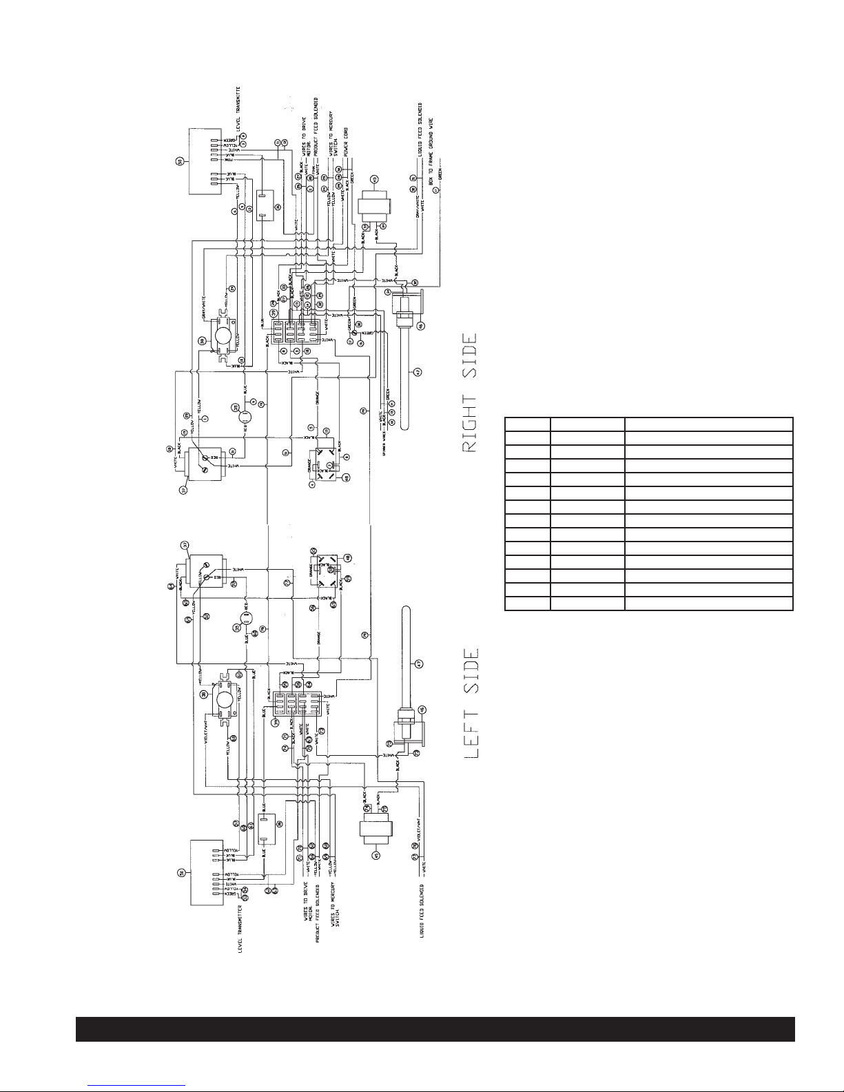
Model 3341A Wiring Diagram
Item Part Number Description
35 W0570007 Indicator Light
36 Product Feed Solenoid
36 W0650050 Level Control
37 W0572032 Transformer Sub-Assy.
38 W0570651 Time Delay Relay
39 W0570235 Terminal Block
40 Liquid Feed Solenoid
41 Level Transmitter
42 Level Transmitter
43 W0572068 Power Cord
45 W0570045 Core & Coil Ballast
46 W0570044 Light Socket
47 W0570043 Florescent Light Bulb
48 W0570924 Switch
Page 27

Crathco®Remote Beverage Freezers Page 25
Model 3341A Ladder Diagram
Page 28

Page 26 Crathco®Remote Beverage Freezers
Exploded View Model 3342 Final Assembly
Exploded View Model 3352 Final Assembly
Item Part Number Description
1 W0151013 Stock Assy. 3352
2 W0600005 Serial Plate
3 W0600224 Owners Manual
4 W0660060 Plastic Bag
5 W0600121 Instr. Sheet, Install Header
6 W0600073 Caution Sheet
7 W0631903 Sanitizer Packets
8 W0430089 Standard Dasher
9 W0800126 L-Block 3312
10 W0800127 Box, 3312
11 W0800128 Top Pad
12 W0800123 Wooden Base Assy.
13 W0890182 Drip Pan Assy.
14 W0520093 Hopper Cover
15 W0890187 Standard Seal Kit
16 W0890220 Leg Kit
17 W1431084 Scraper Blade
Item Part Number Description
1 W0151015 Stock Assy. 3342
2 W0600005 Serial Plate
3 W0600224 Owners Manual
4 W0660060 Plastic Bag
5 W0600121 Instr. Sheet, Install Header
6 W0600073 Caution Sheet
7 W0631903 Sanitizer Packets
8 W0430089 Standard Dasher
9 W0800126 L-Block 3312
10 W0800127 Box, 3312
11 W0800128 Top Pad
12 W0800123 Wooden Base Assy.
13 W0890182 Drip Pan Assy.
14 W0520093 Hopper Cover
15 W0890187 Standard Seal Kit
16 W0890220 Leg Kit
17 W1431084 Scraper Blade
Page 29

Crathco®Remote Beverage Freezers Page 27
Exploded View Model 3342 Stock Assembly
Item Part Number Description
1
W0110013 Valve Studs
3 W0201338 Evaporator Foam Assy.
4 W0211112 Drain Tube Fitting
5 W0211210 Frame Assembly
6 W0340022 213 O-Ring
7 W0340055 O-Ring for Valve Body
8 W0340058 Barrel Gasket
9 W0380025 Modified Flange Bearing
10 W0430024 Blind Flange Bearing
12 W0430028 Stator Weldment
13 W0450053 Sheave
14 W0450209 Belts
15 W0451067 Slush Drive Shaft
16 W0470013 Rubber Pad
17 W0470047 Lubrifilm
18 W0471076 Carburetor Assy.
19 W0480445 Valve Handle
20 W0480450 Valve Body
21 W0570045 Ballast
26 W0570901 Mercury Switch
29 W0572298 Electrical Box Cover
30 W0572307 Light Reflector
32 W0600050 Caution Label
34 W0600214 Warning Label
35 W0600218 Caution Risk of Elec.
36 W0600221 On-Off Clean Decal
Item Part Number Description
59 W0630604 Heyco Strain Relief
60 W0630711 Valve Knobs
63 W0631230 Valve Springs
64 W0631620 Front Display Lens
65 W0631621 Front Display Lens Clear
66 W0641027 Drain Tube Hose
81 W0211222 Base Assembly
85 W0200312 Filter Drier
88 W0572068 Power Supply Cord
89 W0572382 Electrical Box Assembly
90 W0650032 Solenoid Valve
91 W0650116 Capillary Tube
121 W0520093 Hopper Cover
122 W0520102 Rear Panel S.S.
123 W0520081 L.H. Side Panel S.S.
124 W0520082 R.H. Side Panel S.S.
Page 30

Page 28 Crathco®Remote Beverage Freezers
Exploded View Model 3352 Stock Assembly
Item Part Number Description
1
W0110013 Valve Studs
3 W0201348 Evaporator Foam Assy.
4 W0211112 Drain Tube Fitting
5 W0211210 Frame Assembly
6 W0340022 213 O-Ring
7 W0340055 O-Ring for Valve Body
8 W0340058 Barrel Gasket
9 W0380025 Modified Flange Bearing
10 W0430024 Blind Flange Bearing
12 W0430028 Stator Weldment
13 W0450053 Sheave
14 W0450209 Belts
15 W0451067 Slush Drive Shaft
16 W0470013 Rubber Pad
17 W0470076 Lubrifilm
18 W0471076 Carburetor Assy.
19 W0480445 Valve Handle
20 W0480450 Valve Body
21 W0570045 Ballast
26 W0570901 Mercury Switch
29 W0572298 Electrical Box Cover
30 W0572307 Light Reflector
32 W0600050 Caution Label
33 W0650060 Circuit Board
34 W0600214 Warning Label
35 W0600218 Caution Risk of Elec.
36 W0600221 On-Off Clean Decal
Item Part Number Description
54 W0611728 Fas Pin
59 W0630604 Heyco Strain Relief
60 W0630711 Valve Knobs
63 W0631230 Valve Springs
64 W0631620 Front Display Lens
65 W0631621 Front Display Lens Clear
66 W0641027 Drain Tube Hose
76 W0650033 Solenoid Valve
77 W0600180 Autofill Label
78 W0620350 Autofill Tube Connection
79 W0210003 Dual Autofill Sole. Brkt.
80 W0952006 Autofill Tube Assy.
81 W0212222 Base Assembly
85 W0200312 Filter Drier
88 W0572068 Power Supply Cord
89 W0572380 Electrical Box Assembly
90 W1650005 Solenoid Valve
91 W0650116 Capillary Tube
108 W0572365 Mix Low Probe
109 W0630426 Detiker Clamps
Page 31

Crathco®Remote Beverage Freezers Page 29
Exploded View Models 3342/3352 Motor Assembly
Base Assembly Refrigeration Models 3342/3352
Item Part Number Description
1 W0170014 Consistency Cntrl.
2 W0210169 Motor Cradle
3 W0210200 Frame Bottom Plate
4 W0321013 Motor Adj. Nut
5 W0321020 Motor Assembly
6 W0380009 Flange Bearing
7 W0451000 Pulley
Item Part Number Description
2 W0650501 Access Valve
4 W0650104 Automatic Exp. Valve
6 W1650005 Solenoid Valve
7 W0200312 Filter Drier
8 W0620117 3/8" Quick Disconnect
9 W0620118 5/8" Quick Disconnect
21 W0650416 Needle Valve
22 W0650116 Capillary Tube
Page 32

Page 30 Crathco®Remote Beverage Freezers
Electrical Box Model 3342
Electrical Box Model 3352
1
2
3
4
5
7
8
9
10
11
W0570660
W0570924
W0572032
W0570235
W0570044
W0572297
W0572305
W0572306
W0630008
W0631619
Sequencer
Toggle Switch
Transformer
Terminal Block
Light Socket
Elec. Box
Light Bracket L.H.
Light Bracket R.H.
Heyco Bushing
Elec. Box Lens
Item Part Number Description
W0570660
W0570924
W0572032
W0570235
W0570044
W0570910
W0572450
W0572305
W0572306
W0630008
W0631619
W0650050
Sequencer
Toggle Switch
Transformer
Terminal Block
Light Socket
Toggle Switch, Autofill
3312 Elec. Box
Light Bracket L.H.
Light Bracket R.H.
Heyco Bushing
Elec. Box Lens
Liquid Level Control
Item Part Number Description
1
2
3
4
5
6
7
8
9
10
11
12
Page 33

Crathco®Remote Beverage Freezers Page 31
Model 3342 Wiring Diagram
Item Part Number Description
35 W0570007 Indicator Light
36 W0650050 Level Control
37 W0572032 Transformer Sub-Assy.
38 W0570660 Time Delay Relay
39 W0570235 Terminal Block
40 W0650005 Liquid Feed Solenoid
43 W0572068 Power Cord
45 W0570045 Core & Coil Ballast
46 W0570044 Light Socket
47 W0570043 Florescent Light Bulb
48 W0570924 Switch
Page 34

Page 32 Crathco®Remote Beverage Freezers
Model 3342 Wiring Ladder Diagram
Page 35
Crathco®Remote Beverage Freezers Page 33
Model 3352 Wiring Diagram
Item Part Number Description
35 W0570007 Indicator Light
36 W0570910 Switch
37 W0572032 Transformer Sub-Assy.
39 W0570235 Terminal Block
40 W1650005 Liquid Feed Solenoid
41 W0650050 Level Transmitter
42 W0560050 Level Transmitter
43 W0572068 Power Cord
45 W0570045 Core & Coil Ballast
46 W0570044 Light Socket
47 W0570043 Florescent Light Bulb
48 W0570924 Switch
49 W0650033 Product Feed Solenoid
Page 36

Page 34 Crathco®Remote Beverage Freezers
Model 3352 Ladder Diagram
Page 37

Crathco®Remote Beverage Freezers Page 35
Autofill Connections for Models 3341A & 3352
1
2
3
4
5
6
7
8
9
10
Item Part Number Description
Fill Tube
Tube Sleeve
Sleeve Spacer
Terminal Washer Assembly
Tube Connector
Hopper Wall
Solenoid Valve
Liquid Level Control
Proportioning Pump
Bag in the Box
W0952002
W0952005
W0952000
W0952003
W0620350
W0650033
W0650050
Model 3341 Model 3352
1/4” LINE
1/4” LINE
Page 38

Page 39

Page 40

Grindmaster® Coffee Grinders and Brewers • Espressimo® Espresso Machines • Crathco® Hot Beverage Dispensers
Crathco® Cold and Frozen Beverage Dispensers • American Metal Ware® Coffee and Tea Systems
Tel (502) 425-4776 • Fax (502) 425-4664 • 1-800-695-4500
P.O. Box 35020 • Louisville, KY 40232 • USA
www.grindmaster.com • email: info@grindmaster.com
0705 Form # WH-302-02
Part # W0600224
© Grindmaster Corporation, 2000
PRINTED IN USA
 Loading...