

Page 1

USER’S GUIDE
Installation & Operation
Instructions
Tank Farm Transmitter
Model TFT 32
Series 2.4
Pressure Sensor Input (-B-)
Page 2

Note: This page has been left blank intentionally.
Page 3

TFT32 Tank Farm Transmitter
Manual Series 2.4
INDEX
Bench Test and Connections·····································4
Calibration System ············································7
Calibration Menu ·············································8
Calibration Units Selection······································9
Output Span Calibration ········································10
Level Calibration ·············································11
Relay Calibration ·············································15
Damping ····················································16
Transmitter/Tank Address ······································16
Baud Rate ···················································17
Output Simulation·············································17
Store/Save Calibration ·········································17
Enclosure Installation ··········································19
Sensor Installation·············································20
Error/Warning Messages ·······································21
Communication Protocol ·······································22
Fuse Replacement ·············································24
Applications Hotline ···········································25
Product Return Procedure ·······································26
Warranty ···················································27
Conversion Tables ············································30
Specifications ················································31
IMPORTANT NOTE: This instrument is manufactured and calibrated to meet product specifications.
Please read this manual carefully before installation and operation. Any unauthorized repairs or
modifications may result in a suspension of the warranty.
Available in Adobe Acrobat pdf format
Page 3
Page 4
TFT32 Tank Farm Transmitter
Manual Series 2.4
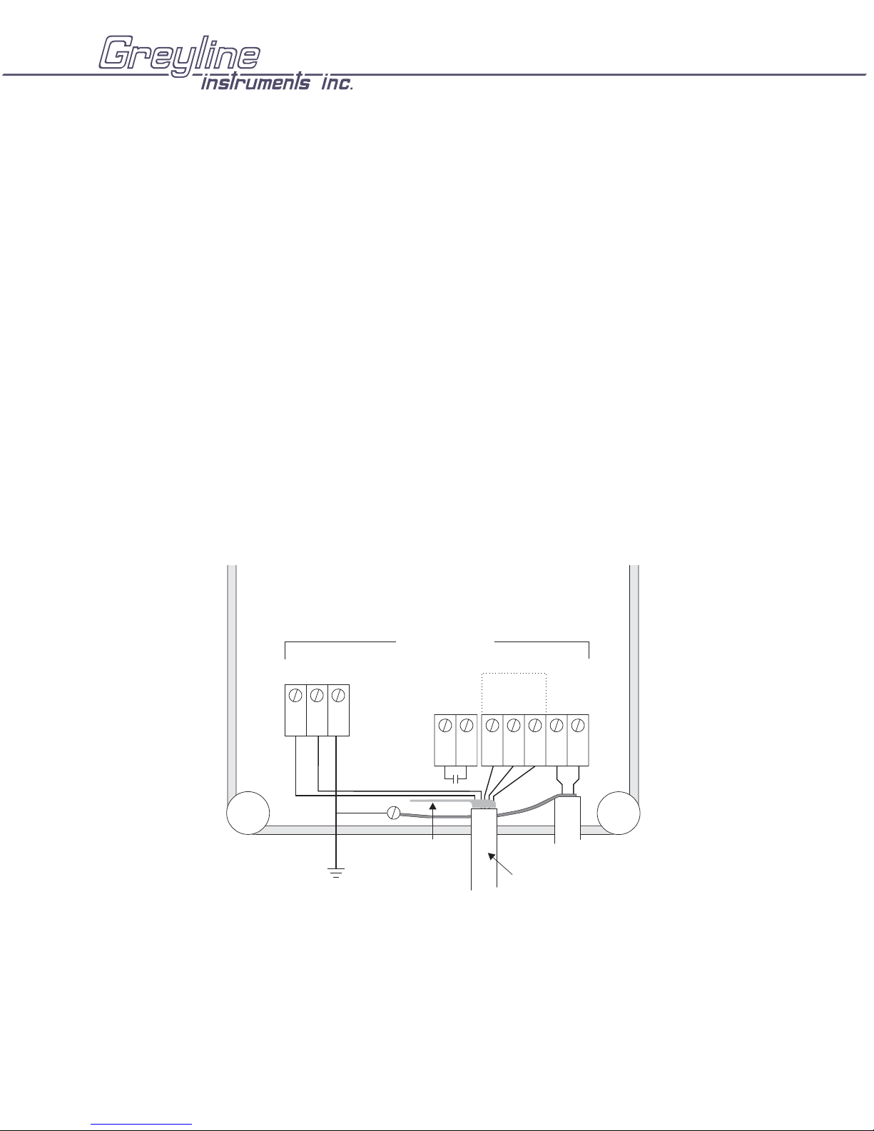
QUICK BENCH TEST (PRESSURE INPUT):
Connect Sensor as shown below, then apply Power. When properly connected figures will be shown on
the LCD display. Test operation of the TFT32 by applying pressure to the sensor or 4-20mA input. The
TFT32 will now display level in inches or cm.
CONNECTIONS:
POWER INPUT: The standard model requires DC power input between 15 to 24VDC with current
consumption of 120mA maximum. Power GND must be connected to a good “earth” ground for surge
protection.
RS485 NETWORK: Connections from the 485 network (other TFT32’s and the PC computer) are:
Data - (D*), Data + (D) and signal/shield ground (S.G.)
IMPORTANT NOTE: To comply with CSA/NRTL standards, power input and relay connection wires
must have a water tight fitting conduit entry to the instrument enclosure.
14 AWG MAX
24VDC
–
+
GND
IMPORTANT:
MUST CONNECT TO A
GOOD GROUND (<1 Ohm)
WITH 14 AWG CONDUCTOR
RELAY
(1 AMP)
CONNECT
TO RS485
NETWORK
CABLE
RS485
D
TO RS485
NETWORK
INPUT
*
18 - 22 AWG RECOMMENDED
mA
D
S.G
+-
BLK
RED
SENSOR
6 - CONDUCTOR SHIELDED
Page 4
Page 5
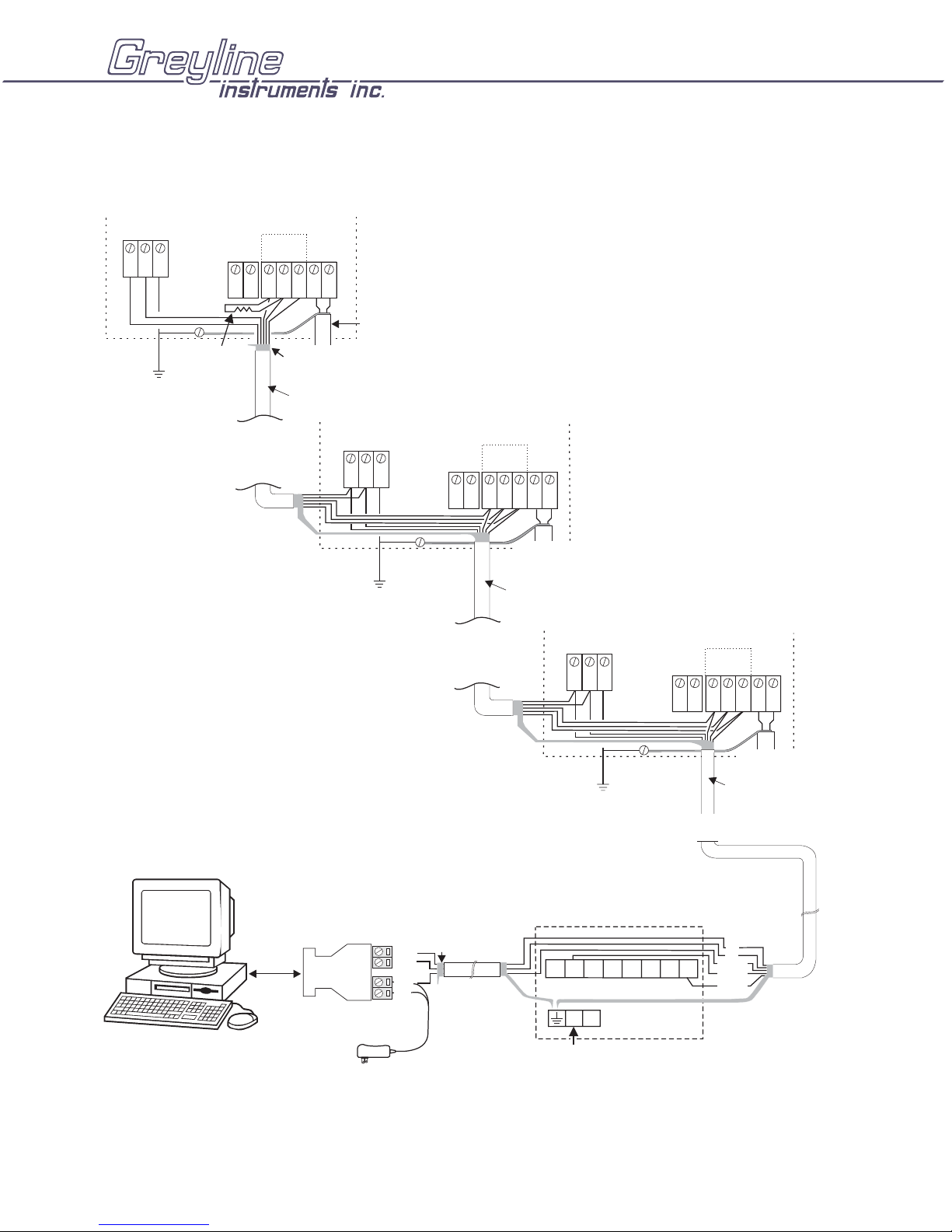
LOCAL NETWORK CONNECTIONS
LAST (FURTHEST) TFT IN THE NETWORK
TFT32 Tank Farm Transmitter
Manual Series 2.4
24VDC
–
+
GND
120 ohm
TERMINATOR
IMPORTANT:
MUST CONNECT TO A
GOOD GROUND (<1 Ohm)
WITH 14 AWG CONDUCTOR
(supplied)
RELAY
(1 AMP)
TO RS485
NETWORK
INPUT
RS485
MORE
TFT'S
mA
*
+-
D
D
S.G
BLK
RED
DO NOT
CONNECT SHIELD
6 - CONDUCTOR SHIELDED
18 - 22 AWG RECOMMENDED
IMPORTANT:
MUST CONNECT TO A
GOOD GROUND (<1 Ohm)
WITH 14 AWG CONDUCTOR
SENSOR
24VDC
+
RELAY
–
GND
(1 AMP)
RS485
*
D
D
S.G
INPUT
mA
+-
RED
BLK
SENSOR
6 - CONDUCTOR SHIELDED
18 - 22 AWG RECOMMENDED
TO RS485
NETWORK
MORE
TFT'S
24VDC
+
RS485
*
D
INPUT
mA
D
S.G
+-
RELAY
–
GND
(1 AMP)
To
RS232
Port
485OI9TB-12V
DB9F
RS232
RS485
RS485/232
CONVERTER
D–
D+
GND
12V
DO NOT
CONNECT
SHIELD
IMPORTANT:
MUST CONNECT TO A
GOOD GROUND (<1 Ohm)
WITH 14 AWG CONDUCTOR
PS150 POWER SUPPLY
S+
V+
V+
V+
V-
V-
NL
115VAC
S-
V-
BLK
RED
SENSOR
6 - CONDUCTOR SHIELDED
18 - 22 AWG RECOMMENDED
TO RS485
NETWORK
D*
D
GND
24V+
24V-
SHIELD
Page 5
Page 6
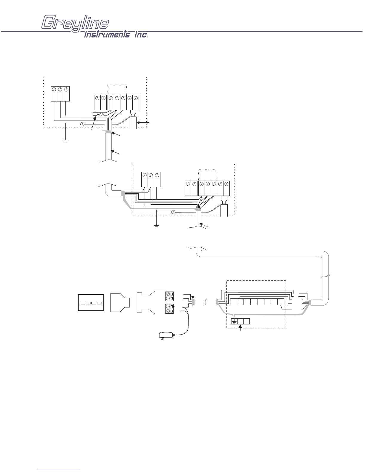
DIAL-UP LOCATION CONNECTIONS
LAST(FURTHEST)TFT IN THE NETWORK
TFT32 Tank Farm Transmitter
Manual Series 2.4
24VDC
–
+
GND
120 ohm
TERMINATOR
IMPORTANT:
(supplied)
MUST CONNECT TO A
GOOD GROUND (<1 Ohm)
WITH 14 AWG CONDUCTOR
RELAY
(1 AMP)
TO RS485
NETWORK
RS485
INPUT
mA
*
+-
D
D
S.G
BLK
RED
DO NOT
CONNECT SHIELD
6 - CONDUCTOR SHIELDED
18 - 22 AWG RECOMMENDED
MORE
TFT'S
IMPORTANT:
MUST CONNECT TO A
GOOD GROUND (<1 Ohm)
WITH 14 AWG CONDUCTOR
24VDC
–
+
SENSOR
GND
RELAY
(1 AMP)
TO RS485
NETWORK
MORE
TFT'S
INPUT
RS485
D
mA
*
+-
D
S.G
BLK
RED
SENSOR
6 - CONDUCTOR SHIELDED
18 - 22 AWG RECOMMENDED
MODEM
DB25M
NULL
MODEM
485OI9TB-12V
DB9M
DB9F
RS232
CONVERTER
RS485
RS485/232
D–
D+
GND
12V
DO NOT
CONNECT
SHIELD
PS150 POWER SUPPLY
S+
V+
V+
V+
V-
V-
V-
NL
115VAC
D*
D
GND
S-
24V+
24V-
SHIELD
Page 6
Page 7
TFT32 Tank Farm Transmitter
Manual Series 2.4
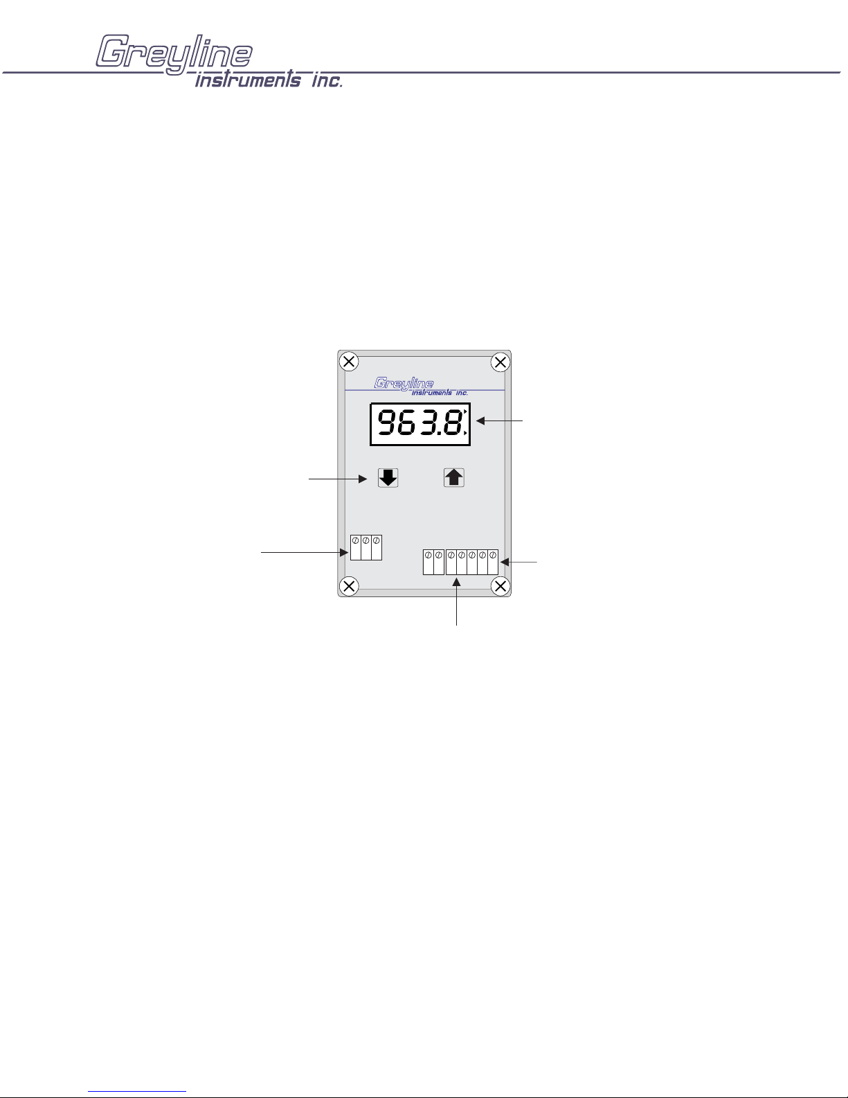
KEYPAD SYSTEM
The TFT32 has a simple 2-key calibration system. Operating and calibration modes are shown on the 4
digit display. The keys are used to calibrate the TFT32, and to view operating mode and functions. If the
keys are not used for 10 minutes, the TFT32 will automatically go to NORMAL MODE. Except in
OUTPUT SIMULATION mode, the Relay and RS485 serial output are not affected by use of the keys
until your calibration is stored.
PERCENT INCHES CM
mA
RELAY
4-DIGIT LCD DISPLAY
CALIBRATION KEYS
TFT32
Tank Farm Level Transmitter
POWER
CONNECTION
+ –
GND
SENSOR
CONNECTION
RS485 NETWORK
CONNECTION
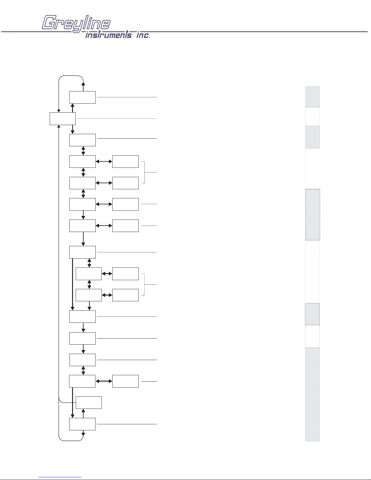
MENU - FLOW CHART
The following diagram shows the TFT32 Menu system. Arrows show the directions to leave a box.
Pressing a corresponding key will move to the next box in the direction shown. Numeric values are
changed by pressing and holding the Ç or È keys.
At the bottom of Menu is a YES? prompt. To store the calibration values permanently (even through
power failure), press the Ç key. If the È key is pressed from the YES? prompt no changes will be
stored and the system will return to NORMAL mode.
Page 7
Page 8
TFT32 CALIBRATION MENU
PRESSURE SENSOR INPUT
TFT32 Tank Farm Transmitter
Manual Series 2.4
See Page
#
20.0
123.4
LEVEL CM
CALU
PERCENT INCHES CM
0=
100= 999.9
LO 1056
HI 1.000
roc1
3,4,5, 6 1,2
ro FF
PERCENT
PERCENT
ron
0.0
CM
CM
CM
CM
100.0
CM
98.0
CM
mA DISPLAY
Displays mA signal as received from sensor
NORMAL MODE
CALIBRATION UNITS SELECTION
Press to select inches, cm, percent or blank (other units)
Ç
OUTPUT SPAN CALIBRATION
"0=" Enter minimum reading to be displayed by the TFT32
"100=" Enter maximum reading to be displayed by the TFT32
Wait for the numeric value then press
decrease.
IN-SITU CALIBRATION
Simulate 4mA with 4-20mA input device and enter the minimum
value of input device.
With level 70% of tank enter the current level.
Simulate 20mA with 4-20mA input device and enter the
maximum value from the input device.
RELAY OPERATION CHOICE.
Press to select: 3 = Signal Loss Only
RELAY SET POINTS
Wait for numeric value and press and to adjust Set Points
(in percentage of Span)
>
Ç
1 = Level Alarm 4 = Always ON
2 = Level + Signal Loss 5 = Always OFF
or to increase or
ÇÈ
ÇÈ
18
9
9
10
11
15
dp10
Ad 1
bd19
100.0OPSL
-C.S-
YES
YES?
NO
DAMPING (0-15 secs)
Press to adjust
Ç
TRANSMITTER/TANK ADDRESS
Press to select 1-32
Ç
SERIAL OUTPUT BAUD RATE
Press to select 19 = 19200 4 = 4800
Ç
OUTPUT SIMULATION
CM
Wait for numeric value and press and to increase or
decrease Simulated Output (Automatically returns to NORMAL
mode in 10 minutes)
STORE YES?
Press to store Calibration (displays -C.S-)
Ç
Press Calibration Not Stored
È
9 = 9600 2 = 2400
ÇÈ
16
16
17
Page 8
Page 9
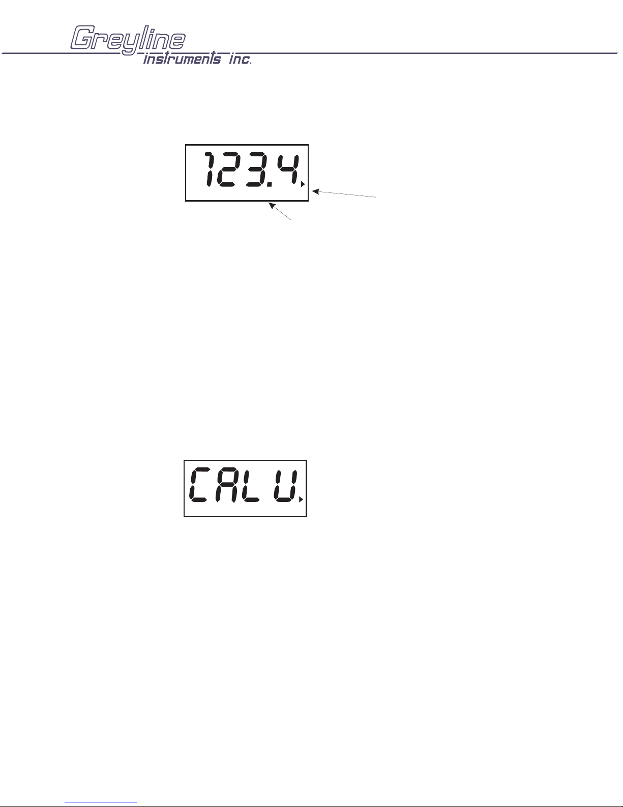
NORMAL MODE
TFT32 Tank Farm Transmitter
Manual Series 2.4
mA
LEVEL CM
The TFT32 Normal Mode
is always Level
CALIBRATION UNITS SELECTION
Press È from NORMAL mode, display will show:
RELAY
ON - Relay energized
OFF - Relay de-energized
PERCENT INCHES CM
È
LEVEL
CALIBRATION
Ç
INCHES
Ç
PERCENT
Ç
BLANK
Ç
CM
Page 9
(Any Units)
Page 10
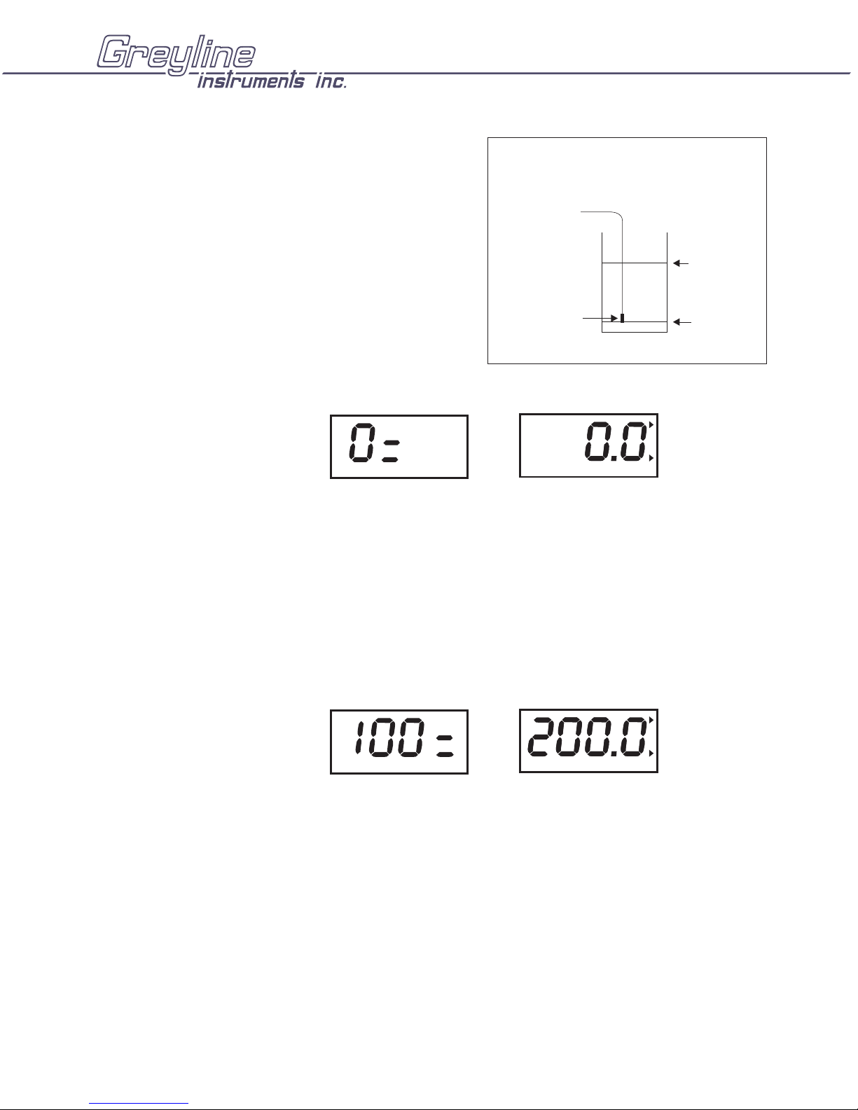
OUTPUT SPAN CALIBRATION
.
.
TFT32 Tank Farm Transmitter
Manual Series 2.4
LEVEL
(Pressure Sensor)
100=
Max Level
The Display will alternate between
È
100=
and
Pressure
Sensor
È
1524
È
1523
È
1522
CM
Ç
0.1
Ç
0.2
Ç
0.3
0=
Zero Level
every 3 seconds
Wait for the numeric value and press Ç to enter the zero level, or minimum level of the tank. With
display on 0 = press È
The Display will alternate between
Wait for the numeric value and press Ç to enter the maximum level of the tank. With display on 100 =
press È.
È
LO
Page 10
and
È
199.9
È
199.8
È
199.7
every 3 seconds
CM
Ç
200.1
Ç
200.2
Ç
200.3
Page 11

LOW LEVEL CALIBRATION (IN-TANK)
.
TFT32 Tank Farm Transmitter
Manual Series 2.4
The Display will alternate between
È
HI
and
È
208.9
È
208.8
È
208.7
every 3 seconds
CM
Ç
209.1
Ç
209.2
Ç
209.3
With tank level <30% of maximum level (100=) wait for the numeric value and press Ç to enter the
current tank level.
HIGH LEVEL CALIBRATION (IN-TANK)
and
CM
every 3 seconds.The Display will alternate between
È
roc 1
È
798.9
È
798.8
È
798.7
Ç
799.1
Ç
799.2
Ç
799.3
With tank level >70% of maximum level (100=) wait for the numeric value and press Ç to enter the
current tank level.
Note: the greater the range between LO and HI levels for this procedure, the better the accuracy of your
calibration. (eg: LO at 10% and HI at 90% will produce a more accurate calibration than LO at 40% and
HI at 60%).
Note: If only one value is changed during a calibration then the second calibration point remains the
unchanged value from the last calibration (ie. You can perform a single point calibration to improve
upon the previous calibration).
Note: Sensor input difference between HI and LO must be greater than 2mA.
Page 11
Page 12

SETUP EXAMPLE: PS11 Sensor in a 70” Tank
TFT32 Tank Farm Transmitter
Manual Series 2.4
Page 12
Page 13

LOW LEVEL CALIBRATION (BENCH)
.
TFT32 Tank Farm Transmitter
Manual Series 2.4
È
HI
and
È
208.9
È
208.8
È
208.7
CM
Ç
209.1
Ç
209.2
Ç
209.3
every 3 seconds.The Display will alternate between
With sensor input OPEN (sensor not connected) wait for the numeric value and press Ç to enter the
level of the sensor in the tank. (eg. If sensor will be mounted at a level of 6 inches then LO = 6.0 inches)
HIGH LEVEL CALIBRATION (BENCH)
The Display will alternate between
and
every 3 seconds
CM
È
roc 1
È
798.9
È
798.8
È
798.7
Ç
799.1
Ç
799.2
Ç
799.3
With sensor input OPEN (sensor not connected) wait for the numeric value and press Ç to enter the high
level:
HI = [20mA Level]
+ LO
Specific Gravity
Where [20mA level] is to be read from the “Pressure Sensor Conversion Chart” (Page 10). The
“Specific Gravity” is the specific gravity of your fluid (=1 for water). “LO” is the Low Level
Calibration value entered above.
Note: See page 12 for samples of bench calibration calculations.
Page 13
Page 14

TFT32 Tank Farm Transmitter
PRESSURE SENSOR CONVERSION CHART (Bench Calibration)
Manual Series 2.4
Examples of “Bench Calibration” Calculations
Example 1 - PS11 sensor
- Specific gravity of tank contents is 1.5
- Sensor is mounted at a level of 6 inches
- Calibration units (CALU) are in inches
LO = 6.0
[20mA Level] = 138.6 inches
HI = [20mA Level]
+ LO = 138.6 + 6.0 = 98.4
Specific Gravity 1.5
Example 2 - PS11 sensor
- Specific gravity of tank contents is 1.0
- Sensor is mounted at a level of 15
- Calibration units (CALU) are in cm
LO = 15.0
[20mA Level] = 352.0 cm
HI = [20mA Level]
+ LO = 352.0 + 15.0 = 367.0
Specific Gravity 1.0
cm
Page 14
Page 15

RELAY OPERATION CHOICE
The TFT32’s Signal Relay can be configured to operate as:
ROC1 = Level Alarm
ROC2 = Level + Signal Loss Alarm
ROC3 = Signal Loss Alarm only
ROC4 = Always ON
ROC5 = OFF (de-energized) at all times
Press Ç to select the ROC.
RELAY CALIBRATION
TFT32 Tank Farm Transmitter
Manual Series 2.4
È
roc = 3,5,6 roc =
ÈÈ
È
1,2,4
Ç
roc2
Ç
roc3
Ç
roc4
ROC1 (Level Alarm)
ROC2 (Level + Echo Loss Alarm) - Relay will be energized when the Relay ON set point is
reached.
or if the signal is lost (e.g. sensor wires short or open).
NOTE: The Set Points are displayed in percentage of span (LEVEL). Two different Set Points (ronand
roFF) allows a Relay “deadband” for Pump Control and to avoid Relay chatter.
Page 15
Page 16

TFT32 Tank Farm Transmitter
4
Manual Series 2.4
Example of Relay Calibration
Span (Max Level) = 184 inches
ron in percent =150/184 = 81.5%
roFF in percent = 30/184 = 16.3%
DAMPING
Normal Setting: dP10
Fast Response (up to ½ inch /13 mm level
change per second): dP5 or less
Slow Response (turbulence) dP15
RON
R OFF
È
30"
150"
Ç
dP11
Ç
dP12
rAn2 = 18
SPAN = 184"
15 SECS.
MAXIMUM
TRANSMITTER/TANK ADDRESS
Select transmitter address 1 to 32 taking into
consideration the following:
1) Each transmitter must have a different address.
2) The address number is also the tank position on the
page when running the TFS Tank Farm Supervisor
PC software.
Page 16
Page 17

BAUD RATE
Select the highest Baud Rate whenever
possible. All Transmitters connected to
the network must have the same Baud
Rate.
OUTPUT SIMULATION MODE
È
Ç
bd 2
Ç
bd 4
TFT32 Tank Farm Transmitter
Manual Series 2.4
bd 19 = 19200
bd 9 = 9600
bd 4 = 4800
bd 2 = 2400
Output Simulation controls the RS485 serial output, digital display and signal relay. Use it to test
Transmitter Communication to the remote PC running TFS software and to test Relay set-points.
Simulation values are in percentage of Span.
TO STORE (SAVE) CALIBRATION
Press Ç to Store calibration (TFT will display -C.S-).
Calibration is stored in non-volatile memory (even through power interruptions).
Press È to return to NORMAL mode without storing any changes.
Page 17
Page 18

mA DISPLAY
e
TFT32 Tank Farm Transmitter
Manual Series 2.4
From Normal Mode press Ç
Displays mA input signal as received from pressure sensor
or 4-20mA transmitter.
mA
Ç
Return to
Normal Mod
Page 18
Page 19

TFT32 Tank Farm Transmitter
Manual Series 2.4
ENCLOSURE INSTALLATION
Locate the enclosure within 10,000 ft (3,000 m) of the pressure sensor. It can be wall mounted with four
mounting screws (supplied) or panel mounted with Option PM Panel Mounting Kit from Greyline
Instruments. Avoid mounting the enclosure in direct sunlight to protect the electronics from damage due
to overheating and condensation. Seal conduit entries to prevent moisture from entering enclosure.
NEMA4X (IP66) WITH CLEAR COVER
COVER
ENCLOSURE
MOUNTING
HOLES
1. Remove enclosure cover.
2. Insert #6 screws through the four enclosure mounting holes to secure
enclosure to wall or mounting stand.
ENCLOSURE
END VIEW
3. Replace Cover
An additional conduit hole can be cut in the end of the enclosure if
required. Use a hole saw or Greenlee-type hole cutter to cut the required
holes.
Note:
1 This non-metallic enclosure does not automatically provide grounding between conduit connections.
Grounding must be provided as part of the installation. Ground in accordance with the requirements
of the National Electrical Code. System grounding is provided by connecting grounding wires from
all conduit entries to the steel mounting plate or another point which provides continuity.
2
Water tight “O” ring seals must be used if cable strain-reliefs are used.
Page 19
Page 20

PST THREADED PRESSURE SENSOR INSTALLATION
R
MAX LEVEL
1/4" NIPPLE
STAINLESS STEEL
CONDUIT
2ft/60cm
MIN LEVEL
PST PRESSURE
SENSOR
TFT32 Tank Farm Transmitter
Manual Series 2.4
RED
BLK
SHIELD
NEMA4 ENCLOSURE
VENTED TUBE MUST
NOT COME IN CONTACT
WITH ANY LIQUID
SHIELDED PAI
TO TFT32
TRANSMITTER
SUBMERSIBLE PRESSURE SENSOR INSTALLATION
SHIELDED PAIR
TO TFT32
TRANSMITTER
To
Transmitter
MAX LEVEL
VENTED TUBE MUST
NOTCOMEINCONTACT
WITH ANY LIQUID
NEMA4 ENCLOSURE
SHIELD
BLK
RED
CONDUIT
MIN LEVEL
Page 20
Page 21

ERROR / WARNING MESSAGES
t
Instrument has detected Sensor connections/cable open
or signal from sensor is too low (0.25mA)
Instrument has detected Sensor connections/cable short
or signal from sensor is too high (23.0mA)
Indicates that the TFT32 has experienced electrical interference strong enough to corrup
the memory. The TFT32 must be reset and recalibrated.
Reset Procedure 1:
procedure: Press and Hold and until the TFT32 displays .
Reset will clear all memory. TFT32 will need recalibration after this
TFT32 Tank Farm Transmitter
Manual Series 2.4
Illegal Span:
Distance between and must be greater
0= 100=
than 2"(5cm).
Distance for (Max Level) must be greater than
(Min Level).
0=
100=
ÈÇ ----
Page 21
Page 22

TFT32 Tank Farm Transmitter
>
3
(
)
Manual Series 2.4
TFT32 COMMUNICATION PROTOCOL
Greyline TFS Tank Farm Supervisor software manages communications with TFT32 Transmitters
automatically. The following Communication Protocol information is supplied for programmers who are
not using the Greyline TFS Tank Farm Supervisor program. Programmers can create their own drivers
to address TFT32 Transmitters through other software programs on PC computers or PLC’s.
The TFT32 uses an ASCII format command/response protocol. The TFT transmits an answer only when
polled with a valid command and address. The Host computer always initiates the command/response
sequence.
Example of command/response sequence:
Command: #%1RA<CR>
Response: *%1RA+959.3000210AA<CR>
COMMAND STRUCTURE:
RESPONSE STRUCTURE:
*%1RA +959.3 0 0 XXX 0 AA <CR>
RESPONSE
PROMPT
#% 1 RA <CR
COMMAND
PROMPT
FOR TFT32
ADDRESS
A-W = 10-
TFT DATA
(SEE TEXT)
COMMAND
(MUST BE
CAPITAL
LETTERS)
TANK/T FT
1-9 = 1-9
0=LEVEL
CARRIAGE
RETURN
2
MODE
RELAY
STATUS
0=OFF
1=ON
CARRIAGE
RETURN
UNITS
0=cm
TEMP
IN °C
XXX
N/A
CHECKSUM
IN HEX
Page 22
Page 23

COMMAND SET
>
TFT32 Tank Farm Transmitter
Manual Series 2.4
COMMAND DEFINITION COMMAND MESSAGE
(Address 1)
RA Read all
parameters
RS Read Span
(Max Level)
NBxx New Baud Rate
xx = 00 = 38400
01 = 19200
02 = 9600
03 = 4800
04 = 2400
RR Remote Reset
!RR Broadcast Reset
#%1RA<CR> *%1RA+959.300X
#%1RS<CR> *%1RS+999.900X
#%1NBxx<CR>
(TFT will change to new
Baud Rate only after
reset)
#%1RR<CR>
#%!RR<CR>
(All units in the Network
will reset)
TFT RESPONSE:
TFT Data: Valid analog Data Range is + 000.0 to + 6550.
Values with (-) sign represent error messages
TYPICAL RESPONSE
X
X0AA<
X0BF<CR
X
*%1NB02
*1RR
(No Response)
CR>
- 100.0 = “Not Ready Please Wait”
- 101.0 = “Signal Lost”
- 102.0 = “Sensor Short”
- 103.0 = N/A
- 104.0 = “Sensor Open”
- 105.0 = N/A
- 106.0 = N/A
- 107.0 = N/A
Units and mode: Always cm and Level.
Page 23
Page 24

FUSE REPLACEMENT
P
REMOVE
TFT32
Tank Farm Transmitter
TFT32 Tank Farm Transmitter
Manual Series 2.4
1. Disconnect Power
2. Remove 2 top screws
3. Pull and flip chassis
4. Remove 0.5 amp fuse with long nose pliers
5. Install new fuse
(Replacement Greyline Part #1/2 Amp PCC))
PULL AND
FLIP
0.5 AMP
FUSE
RELAY
SOFTWARE CHI
Page 24
Page 25

TFT32 Tank Farm Transmitter
Manual Series 2.4
APPLICATIONS HOTLINE
For applications assistance, advice or information on any Greyline Instrument contact your Sales
Representative, write to Greyline or phone the Applications Hotline below:
United States: Tel: 315-788-9500 Fax: 315-764-0419
Canada: Tel: 613-938-8956 Fax: 613-938-4857
Toll Free: 888-473-9546
Email: info@greyline.com
Web Site: www.greyline.com
Greyline Instruments Inc.
Canada USA:
16456 Sixsmith Drive 105 Water Street
Long Sault, Ont. K0C 1P0 Massena, NY 13662
Page 25
Page 26

TFT32 Tank Farm Transmitter
Manual Series 2.4
PRODUCT RETURN PROCEDURE
Instruments may be returned to Greyline for service or warranty repair.
Obtain an RMA Number from Greyline -
1
Before shipping a product to the factory please contact Greyline by telephone, fax or email to obtain
an RMA number (Returned Merchandise Authorization). This ensures fast service and correct billing
or credit.
When you contact Greyline please have the following information available:
1. Model number / Software Version
2. Serial number
3. Date of Purchase
4. Reason for return (description of fault or modification required)
5. Your name, company name, address and phone number
Clean the Sensor/Product -
2
Important
1. Rinse sensor and cable to remove debris.
2. If the sensor has been exposed to sewage, immerse both sensor and cable in a solution of 1 part
household bleach (Javex, Clorox etc.) to 20 parts water for 5 minutes. Important: do not immerse open
end of sensor cable.
3. Dry with paper towels and pack sensor and cable in a sealed plastic bag.
4. Wipe the outside of the enclosure to remove dirt or deposits.
5. Return to Greyline for service.
3
Ship to Greyline After obtaining an RMA number please ship the product to the appropriate address below:
: unclean products will not be serviced and will be returned to the sender at their expense.
Canadian and International USA
Customers: Customers:
Greyline Instruments Inc. Greyline Instruments Inc.
16456 Sixsmith Drive 105 Water Street
Long Sault, Ont. K0C 1P0 Massena, NY 13662
RMA# RMA#
Page 26
Page 27

TFT32 Tank Farm Transmitter
LIMITED WARRANTY
______________________
Greyline Instruments warrants, to the original purchaser, its
products to be free from defects in material and workmanship for
a period of one year from date of invoice. Greyline will replace
or repair, free of charge, any Greyline product if it has been
proven to be defective within the warranty period. This warranty
does not cover any expenses incurred in the removal and
re-installation of the product.
Manual Series 2.4
If a product manufactured by Greyline should prove defective
within the first year, return it freight prepaid to Greyline
Instruments along with a copy of your invoice.
This warranty does not cover damages due to improper
installation or handling, acts of nature, or unauthorized service.
Modifications to or tampering with any part shall void this
warranty. This warranty does not cover any equipment used in
connection with the product or consequential damages due to a
defect in the product.
All implied warranties are limited to the duration of this
warranty. This is the complete warranty by Greyline and no
other warranty is valid against Greyline. Some states do not
allow limitations on how long an implied warranty lasts or
limitation of incidental or consequential damages, so the above
limitations or exclusions may not apply to you.
This warranty gives you specific legal rights, and you may also
have other rights which vary from state to state.
Greyline Instruments Inc.
Page 27
Page 28

PS150 POWER SUPPLY
O
150 Watt Power Supply for TFT32 Tank Farm System
Powers up to 32 Greyline TFT32 Transmitters + 6 RB12 Relay Boards
TFT32 Tank Farm Transmitter
Manual Series 2.4
CONDUIT
ENTRY
LOCATION
SIDE VIEW
SPECIFICATIONS PS150 POWER SUPPLY
Power Input: PS150-AI: 90-132VAC, 47-63Hz
PS150-EI: 180-264VAC, 47-63Hz
AC Input Current: PS150-AI: 4A maximum
PS150-EI: 2A maximum
Fuse: 4A, 250V
Operating Temperature: 32 to 122°F(0to50°C)
Storage Temperature: -13 to 185°F (-25 to 85°C)
Enclosure: Watertight, dust tight NEMA4X (IP 66) fiberglass
Safety Approvals: UL 1950
CSA 22.2 1402C Level 3
TUV EN 60950 (IEC 950)
-V
24 VDC
L
-V
115VAC
CATION
+V +V
CONDUIT ENTRY
L
N
Page 28
Page 29

TFT32 Tank Farm Transmitter
Manual Series 2.4
MODEL 485OI9TB-24V
RS232/RS485 Converter
Converts RS485 signals from a TFT32 Transmitter to RS232 for connection to a PC Computer or
Modem.
DB9 RS232 Connector plugs directly into your computer’s
–
COM port
Optically isolates and protects your computer’s RS232 port
–
Terminal block for RS485 connections
–
Operates from 2400 up to 19.2K baud
–
Terminal connections are provided for RS485 D-, D+, 24V
–
and GND
Terminal connections are provided for RS485 Data – (D*), Data + (D),and RS485 power and ground.
The RS485 side of the converter is internally biased and terminated to operate with a RS485 network of
up to 32 devices.
FROM GREYLINE
OR
TFT TRANSMITTERS
IN RS485 NETWORK
D* (D-)
D(D+)
S.G.
TO PC
COM PORT
or MODEM
CABLE
485OI9TB-12V
DB9F
RS232
RS485
D–
D+
GND
12V
FROM GREYLINE
TRANSMITTER
WITH RS485 OUTPUT
(OPTION RS5)
DATA*
DATA
GND
DO NOT CONNECT CABLE SHIELD
Page 29
Page 30

TFT32 Tank Farm Transmitter
CONVERSION
GUIDE
FROM TO MULTIPLY BY
US GALLONS CUBIC FEET 0.1337
US GALLONS IMPERIAL GALS 0.8327
US GALLONS LITRES 3.785
US GALLONS CUBIC METERS 0.003785
LITRES/SEC GPM 15.85
LITRES CUBIC METERS 0.001
BARRELS US GALLONS 42
BARRELS IMPERIAL GALS 34.9726
BARRELS LITRES 158.9886
INCHES MM 25.4
DEGREES F DEGREES C
(°F-32) x 0.556
POUNDS KILOGRAMS 0.453
PSI BAR 0.0676
FOOT² METER² 0.0929
PSIG FEET (H
PSIG METER (H
20) 2.31
20) 0.70
PSIG BAR 0.0666
Manual Series 2.4
VOLUME CALCULATION FOR ROUND TANKS: 3.142 x R² x H
R = TANK RADIUS (½ TANK DIAMETER)
H = TANK HEIGHT
Page 30
Page 31

SPECIFICATIONS:
m
TFT32 Tank Farm Transmitter
Manual Series 2.4
Electronics Enclosure: NEMA4X (IP 67), watertight and dust tight,
fiberglass with clear, shatterproof Lexan cover
Accuracy: 0.25% F.S., Repeatability: 0.1% F.S., Linearity:
0.1%F.S.
Display: ¾” / 19mm high, 4 digit LCD
Programming: 2-button Menu selection. Calibration parameters
are permanent when Stored (even through power
interruptions)
Power Input: 24VDC, 120mA max., 2.9 W (max.)
Optional: 100-130VAC 50/60 Hz, (4.2 W max.)
Optional: 200-260VAC 50/60 Hz, (4.8 W max.)
Fuse: internal, rated 1A
Output: Isolated RS485
Signal Relay: Qty 1, rated 120/240 VAC or 24VDC, 1 ampere
Temperature Compensation: Automatic, temperature probe built in to level
Sensor
Electrical/Surge Protection: Sensor, RS485 and power input
Operating Temperature: -13 to 140°F (-25 to 60°C)
(Electronics)
SUBMERSIBLE PRESSURE SENSOR
Mounting
6.18"
157 mm
Mounting
4.21"
107 mm
TFT32
Tank Farm Level Transmitter
4.92"
125 mm
END VIEW
61.89"
75 m
2.95"
75 mm
Wetted Materials: 303 Stainless steel body with uPVC nose cone
Accuracy: ±0.25% FSO (RSS) includes non-linearity,
hysteresis and non-repeatability
Long term stability: 0.1% / 12 months
Operating Temperature: -13°Fto212°F (-25°Cto100°C)
Compensated Temperature: 14°Fto176°F (-10°Cto80°C)
Output: 4-20mA 2-wire Transmitter
Load Impedance: 1000 ohms max at 24VDC
Proof Pressure: 1.5 times full scale pressure range (or URL)
Burst Pressure: 3 times full scale pressure range (or URL)
Cable: Polyurethane jacketed 4-core with vent tube and strain
wire - rated IP68
Connection: RED = +, BLUE = –, WHITE = SHIELD
MODEL MEASUREMENT RANGE CABLE
LENGTH
PS11S 5 PSIG (11.55 ft) / 0.3 bar (3.15 m) 20 ft / 0.6 m
PS17S 7.5 PSIG (17.33 ft) / 0.5 bar (5.25 m) 23 ft / 7 m
PS23S 10PSIG(23.10ft)/0.67bar(7.04m) 30ft/9m
PS35S 15 PSIG (34.65 ft) / 1.0 bar (10.50 m) 40 ft / 12 m
PS46S 20 PSIG (46.20 ft) / 1.3 bar (13.65 m) 55 ft / 17 m
PS69S 30 PSIG (69.30 ft) / 2.0 bar (21.00 m) 75 ft / 23 m
PS102S 44 PSIG (101.64 ft) / 3.0 bar (31.50 m) 105 ft/ 32 m
PS170S 72 PSIG (166.32 ft) / 5.0 bar (52.50 m) 174 ft / 53 m
5.50"
140 mm
0.985"
25 mm
Page 31
Page 32

THREADED CONNECTION PRESSURE SENSOR
Wetted Materials: 316 and 15-5 PH Stainless steel
Enclosure Material: 316 stainless steel
Accuracy: ±0.25% FSO (RSS) includes non-linearity,
hysteresis and non-repeatability
Operating Temperature: -20°F to 190°F (-29°C to 88°C)
Compensated Temperature: 0°F to 180°F (-18° to 82°C)
Output: 4-20mA 2-wire Transmitter
Load Impedance: 600 ohms max at 24VDC
Proof Pressure: 2 times full scale pressure range (or URL)
Burst Pressure: 5 times full scale pressure range (or URL)
Pressure Response: Less than 5 ms to 90%
Pressure Connection: 1/4" NPT (Female)
Electrical Cable: 2’ (0.6 m) long molded polyrethane jacket,
6-conductor with breather tube
Connection: RED = +, BLACK = –, SHIELD = SHIELD
Model Measurement Range
PS11T 5 PSIG (11.55 ft) / 0.3 bar (3.15 m)
PS17T 7.5 PSIG (17.33 ft) / 0.5 bar (5.25 m)
PS23T 10 PSIG (23.10 ft) / 0.67 bar (7.04 m)
PS35T 15 PSIG (34.65 ft) / 1.0 bar (10.50 m)
PS46T 20 PSIG (46.20 ft) / 1.3 bar (13.65 m)
PS69T 30 PSIG (69.30 ft) / 2.0 bar (21.00 m)
PS115T 50 PSIG (115.50 / 3.45 bar (36.23 m)
PS173T 75 PSIG (173.25 / 5.2 bar (54.60 m)
TFT32 Tank Farm Transmitter
Manual Series 2.4
1/2" NPT
CONDUIT
END
1.25" FLATS
31.75 mm
3.471"
0.380"
9.65 mm
(FEMALE)
88.16 mm
1/4" NPT
1.250"
31.8 mm
1.50"
37.65 mm
Page 32
 Loading...