


SLT

www.greyline.com
USER'S GUIDE
Installation & Operation
Instructions
Level & Flow Monitor
Model SLT 5.0
Manual Series A.1.7

Note: This page has been left blank intentionally.

SLT 5.0 Level and Flow Monitor
INDEX
CONNECTIONS: ............................................................................................... 4
KEYPAD SYSTEM ............................................................................................ 6
CALIBRATION MENU ..................................................................................... 7
ICONS ................................................................................................................. 8
MAIN DISPLAY ................................................................................................ 9
MESSAGE ICON ............................................................................................... 9
STATUS ............................................................................................................. 9
PASSWORD ..................................................................................................... 10
UNITS/MODE .................................................................................................. 11
CALIBRATION................................................................................................ 12
CHANNEL SETUP .......................................................................................... 15
RELAY PARAMETERS .................................................................................. 16
SPECIAL FUNCTIONS ................................................................................... 17
SENSOR MOUNTING/LOCATION ............................................................... 19
SENSOR MOUNTING METHODS ................................................................ 21
ERROR/WARNING MESSAGES ................................................................... 26
FIELD TROUBLESHOOTING ....................................................................... 27
APPLICATIONS HOTLINE ............................................................................ 31
PRODUCT RETURN PROCEDURE .............................................................. 32
APPENDIX A - OPTIONS ............................................................................... 34
DATA LOGGING (Optional) ........................................................................... 40
CONVERSION GUIDE ................................................................................... 42
SPECIFICATIONS ........................................................................................... 43
IMPORTANT NOTE: This instrument is manufactured and calibrated to meet product specifications.
Please read this manual carefully before installation and operation. Any unauthorized repairs or
modifications may result in a suspension of the warranty.
Available in Adobe Acrobat pdf format
Page 3

SLT 5.0 Level and Flow Monitor
CONNECTIONS:
POWER INPUT: The standard model requires AC power input between 100 to 240 VAC 50/60Hz . No
adjustments are necessary for voltages within this range.
Optional DC input model requires 9-32 VDC/9 Watts. Connect to + and - terminals.
Optional Thermostat and Heater modules are available rated for 115 VAC or 230 VAC.
IMPORTANT NOTE: To comply with CSA/UL electrical safety standards, AC power input and relay
connection wires must have conduit entry to the instrument enclosure. Installation requires a switch,
overcurrent fuse or circuit breaker in the building (in close proximity to the equipment) that is marked
as the disconnect switch.
Risk of electric shock. Loosen cover screw to access connections. Only qualified personnel should
!
access connections.
Note: Use of instrumentation over 40°C ambient requires special field wiring.
Note: User replaceable fuse is 2 Amp 250V (T2AL250V).
Page 4
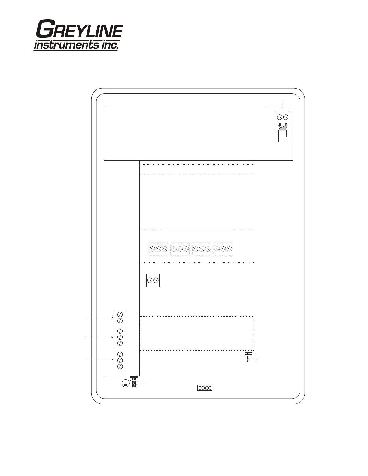
CONNECTIONS
DATA LOGGER OPTION
SLT 5.0 Level and Flow Monitor
SENSOR
SHLD
CORE
GRN
WHT
4-20mA
RLY2
RLY1
–
+
NO
C
NC
NO
C
NC
EXTRA RELAYS OPTION
NC
RLY3
AC
LN
AC
GND
NC
C
POWER
INPUT
C
NO
NO
RLY4
HEATER OPTION
USB HARNESS
CONNECTOR
NC
C
RLY5
NC
NO
RLY6
SENSOR
C
NO
GND
Page 5
SLT 5.0 Level and Flow Monitor
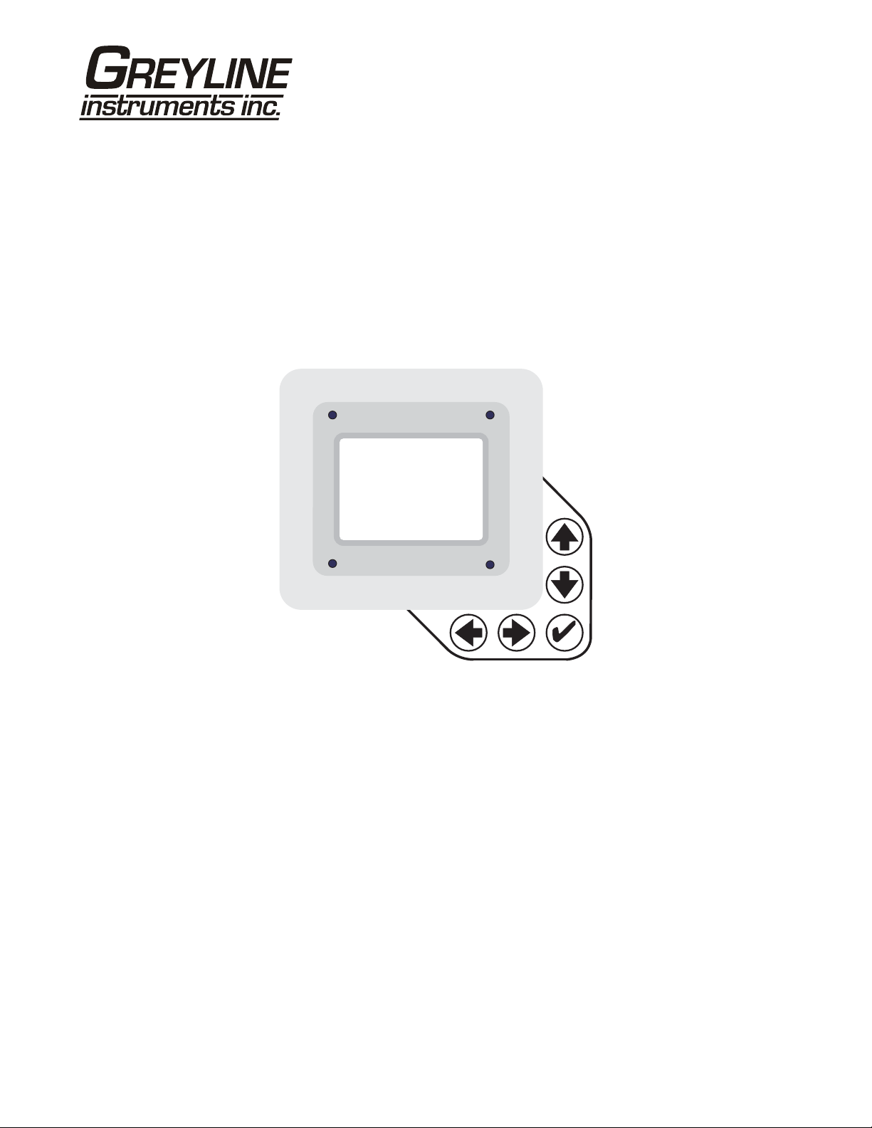
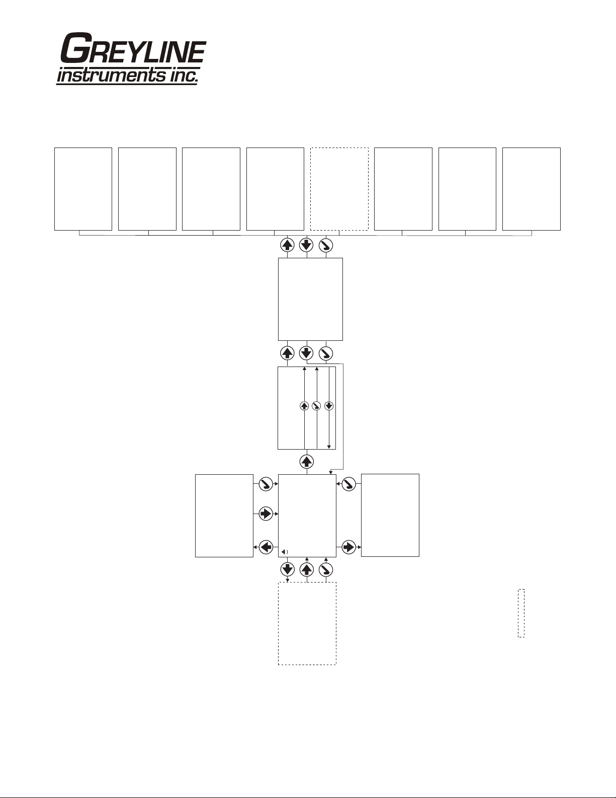
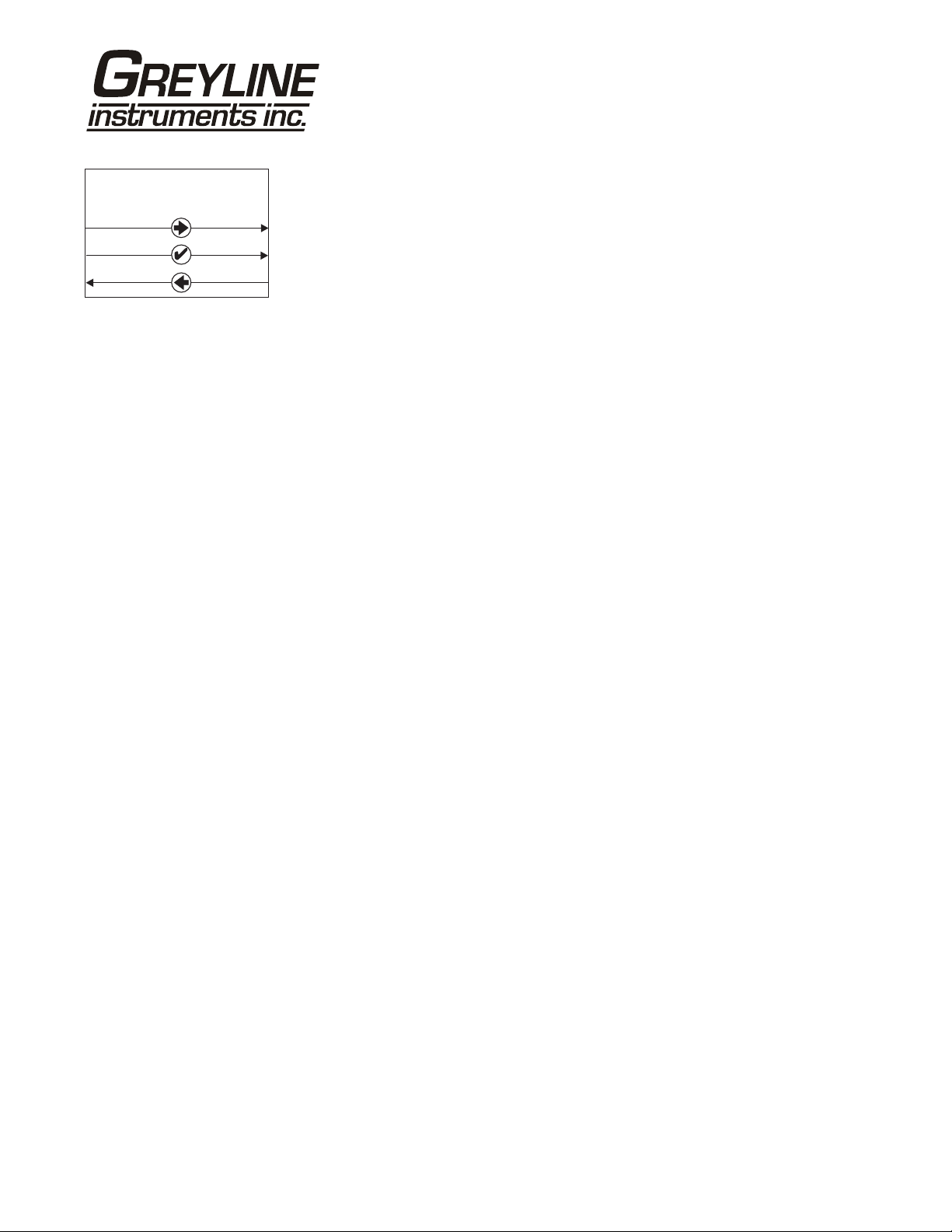
KEYPAD SYSTEM
The following diagram shows the SLT 5.0 menu system. Arrows show the four directions to leave a
menu box. Pressing a corresponding keypad arrow will move to the next item in the direction shown.
Move the cursor (highlighted) under numerals and increase or decrease numerals with the and
keys.
To store calibration values permanently (even through power interruptions), press the .
Page 6
CALIBRATION MENU
FlowFunction
8000 USG/mOff
10000 USG/mOn
May 30 13Set Date /20
SLT 5.0 Level and Flow Monitor
6Relays
24Logger 1. T
1.} 25.01
Mode} Flow
Linear ft
Volume USG
Time min
--Units/Mode--------
Temperature C
--Calibration-------
Min Range 1.000ft}
Max Range 12.000ft
Damping 10%
LOE Time 30sec
Size 22.5°
Type V-notch}
-- ----Channel Setup--
Relay 1}
Mode Pump
LOE mode Off
--Relay Parameters--
Alternate No
--Data Logging-------
SetupChannel
Units / Mode}
Calibration
Relay Parameters
--Menu Selections----
Password 0000
--Password----------
USG/m
Log Site ID 0}
Mode Flow
Set Time 14:24:40
Interval 30sec
Log NO
Data Logging
Special Functions
Simulation
Configuration
Language English}
Analog Out 4-20mA
Backlight High
Reset Totalizer NO
Restore Defaults NO
--Special Functions-
New Password 0000
--Simulation--------
Flow 250USG/m
4-20mA Flow 4.00
Relays 1 2 3 4 5 6
}Test Actual
Utility
Sonar 1.15
--Configuration-----
Analog Out 1
0.000
Data log Stopped
Log Used 0%
Sensor Good
Temperature 21C
--Message-----------
Date Feb. 12/20} 13
--24 hr log----------
Page 7
Tot 20130.8 USG
Relays 1 2 3 4 5 6
9:15:00Min Time
11:08:00Max Time
50138 USGTotal
52.20 USG/mMaximum
0.000 USG/mMinimum
34.82 USG/mAverage
Range 1.00ft}
Tot 0.000ft³
EC 100%
Relays 1 2 3 4 5 6
--Status------------
OPTIONAL FEATURES
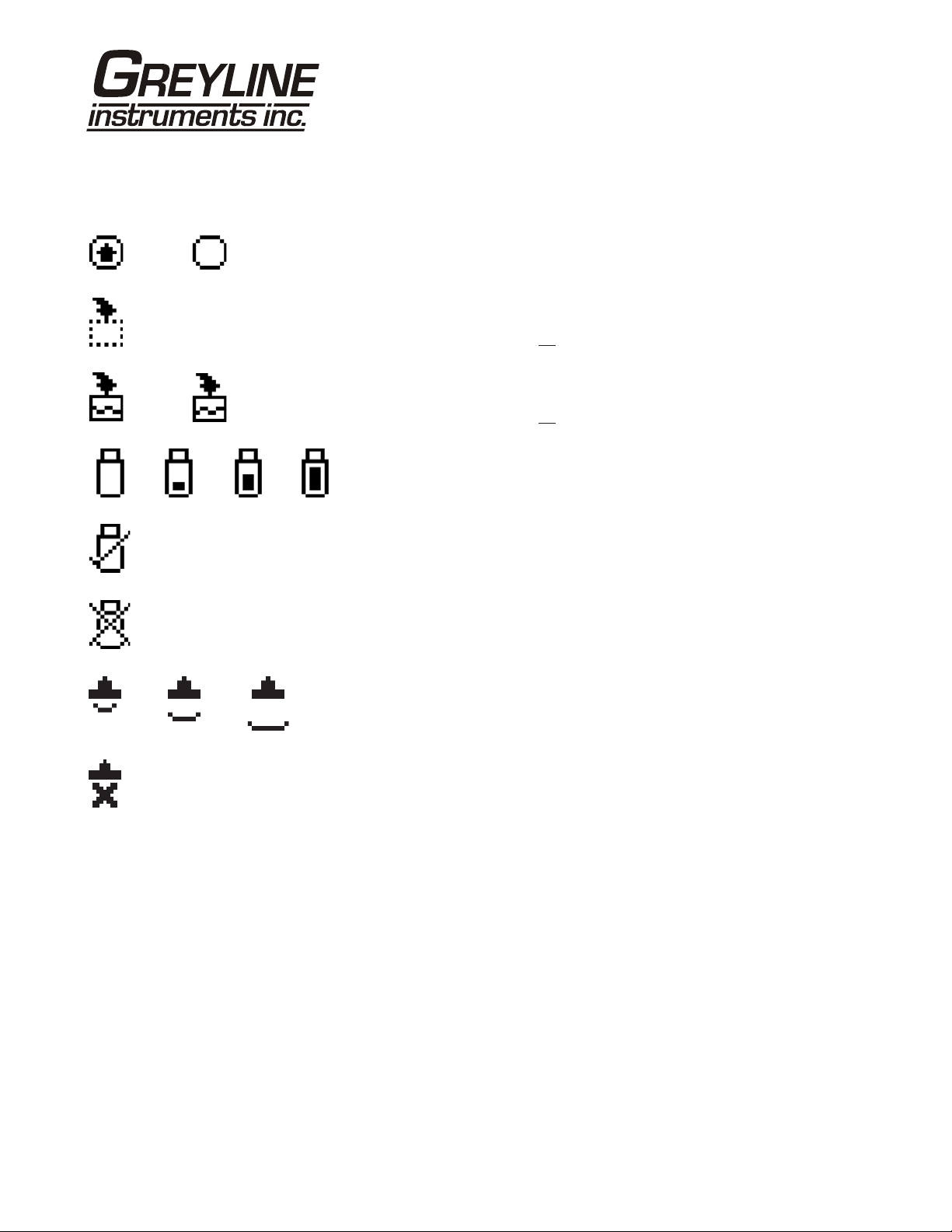
ICONS
SLT 5.0 Level and Flow Monitor
1. 2.
1.
1.
2.
2. 3.
4.
Message waiting. Press .Ç
Data logging .off
Data logging .on
USB file download.
File download completed.
Download Error.
1.
3.2.
Echo OK.
No Echo .
Page 8
SLT 5.0 Level and Flow Monitor
USG/m
0.000
Tot 20130.8 USG
Relays 1 2 3 4 5 6
--Message----------Data log Stopped
Log Used 0%
Sensor Good
Temperature 21C
--Status------------
Range 1.00ft
}
Tot 0.000ft
EC 100%
Relays 1 2 3 4 5 6
--24 hr log---------Date Feb. 12/2010
}
Total 50138 USG
Average 34.82 USG/m
Maximum 52.20 USG/m
Max Time 11:08:00
Minimum 0.000 USG/m
Min Time 9:15:00
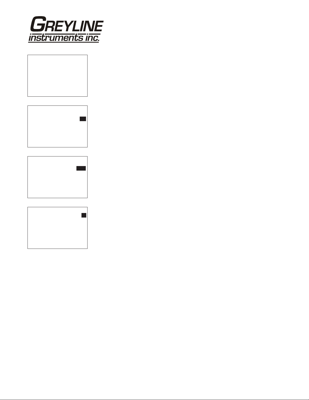
MAIN DISP LAY
The main display shows the units selected from the Units/Mode menu, Level,
Range, Flow, HRT, and Volume rate being measured, TOTALIZER and RELAY
states. The SLT 5.0 will start-up with this display.
MESSAGE ICON
Press from the main display to view status of the data logger and error/warning
messages provided by the instrument. The Message Icon will appear on the main
display if error messages are being generated by the instrument. Refer to the
manual section Error/Warning Messages for a description. Press to return to the
main display.
STATUS
³
Press from the main display to view instrument status. Range will be displayed
in linear units.
Tot Displays the current totalizer reading.
EC Displays echo confidence.
Relays Energized relays will display as a white character on a black
background.
24 HR LOG (Data Logging option only)
Press from the main display to view a formatted flow report from instruments
with a built-in data logger. Press to scroll down one day or repeatedly to scroll
to a specific date. Up to 365 days can be stored. Newest date will overwrite the
oldest. Press to return to the main display.
Page 9
SLT 5.0 Level and Flow Monitor
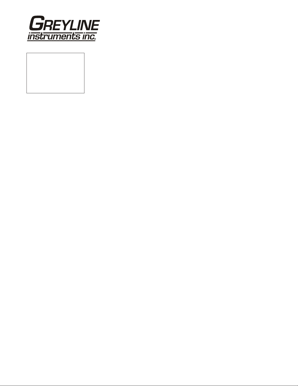
--Password----------
Password 0000
PASSWORD
The password (a number from 0000 to 9999) prevents unauthorized access to the
Calibration menu.
From the Main display press the key to get to
password is 0000 and if it has not been changed press the to proceed to the
Menu Selections screen.
If a password is required, press to place the cursor under the first digit and or
to set the number, then to the second digit, etc. Press or to proceed to
the Menu Selections screen.
A new password can be stored by going to
Password
.
Password. Factory default
Special Functions/New
Page 10
SLT 5.0 Level and Flow Monitor
--Units/Mode-------Mode Flow
}
Linear ft
Volume USG
Time min
Temperature C
--Units/Mode--------
Mode Flow
Linear} in
--Units/Mode--------
}Volume USG
ft3
bbl
IMG
USMG
--Units/Mode-------Temperature} C
ft
mm
m3
IG
UNITS/MODE
From
Flow, HRT or Volume.
Mode press the and then the or to select Level, Range,
Range mode displays distance from the sensor to the target or liquid surface
like a tape measure. Range mode is useful to measure the exact
distance from the sensor to the zero level during calibration, or to
monitor "outage" or free space in a tank.
Level mode can be used to measure tank level in linear units, or "Head"
m
(height of flow) in an open channel for comparison with a flume
manufacturer's flow tables.
Volume Volume mode displays tank inventory in engineering units like
gallons or liters.
HRT Horizontal Round Tank mode sets the SLT 5.0 to calculate and
display volume units in a horizontal round tank.
L
Flow mode is for open channel flow through a flume or weir.
From
Volume HRT or Flow press to make your selection. (Range or
Level mode will bypass the Volume units selection menu). Volume Hrt or Flow
modes will give you the additional choice of volumetric units:
F
ft3 - cubic feet
USG - US gallons
USMG - US million gallons (FLOW only)
IG - Imperial gallons
IMG - Imperial million gallons (FLOW only)
m3 - cubic meters
L - liters
bbl - U.S. oil barrel
Press the to store your selection then the to the next menu item and to
enter.
Linear
press the key and then the or to select your units
of measurement. Press the to store your selection.
Time
press and then or to select
sec.
or
day, hr, min
Temperature
press and then or to select C or F
(Centigrade or Fahrenheit).
Press or to return to the Menu Selections screen.
Page 11
SLT 5.0 Level and Flow Monitor
--Calibration------Min Range 1.000ft
}
Max Range 12.000ft
Damping 10%
LOE Time 30sec
CALIBRATION
Press the to
Calibration and to enter. Use or to position
before each menu item and to enter. When settings are completed press to
store and return to the Calibration menu.
Min Range Distance from the sensor face to highest expected level.
Max Range Distance from sensor to Zero level.
MaxVol For Volume and HRT mode only. Enter the maximum volume of
the vertical or horizontal tank.
Damping Minimum damping allows fast response to level changes.
Increasing damping slows the SLT 5.0's response to level changes
and is ideal to smooth the display and outputs in turbulent
conditions. Damping value is shown in percent (0-99%). Some
experimentation may be required to select the optimum damping
value. A value of 1% is recommended for most applications. For
fast level changes (up to ½ inch/sec - 13 mm/sec), a Damping
value of 1% is recommended.
LOE Time Press and or to change the number of seconds without
receiving an echo before the SLT 5.0 displays ECHO LOSS, and
Control relays change state as calibrated under Relay Parameters.
Factory default is 30 seconds and is recommended for most
applications, Minimum is 1 second and maximum is 99 seconds.
Press to return to Menu Selections.
Page 12
SLT 5.0 Level and Flow Monitor
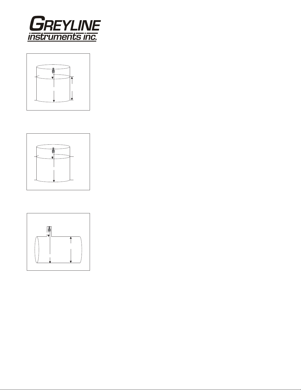
TAN KINVENTORY
LEVEL MODE
SENSOR
MAX RANGE
100%
MIN RANGE
0%
TAN KINVENTORY
RANGE MODE
SENSOR
MAX RANGE
0%
100%
MIN RANGE
TAN KINVENTORY
HORIZONTAL ROUND TANK(HRT)MODE
MIN RANGE
MAX
VOLUME
MAX RANGE
MAX LEVEL
MAX
VOLUME
ZERO LEVEL
MAX LEVEL
ZERO LEVEL
CALIBRATION
- for Level/Inventory Applications
1. Before starting the calibration determine:
a) MAX RANGE = ________________
(Maximum range = distance from Sensor to Zero level)
b) MAX LEVEL = ________________
(Maximum level of product being measured)
c) MIN RANGE = ________________
(Distance from sensor to Max Level)
Minimum range = MAX RANGE - MAX LEVEL
(must be at least 8" / 203 mm depending on sensor model)
2. Check the maximum range with the sensor installed by:
a) When liquid is at zero level press to view the Range reading in the
Status menu. Use this range measured by the SLT 5.0 as the Max Range
setting.
or
b) Carefully measure distance from sensor to zero level with a tape measure,
and use this measurement as the Max Range setting.
MINIMUM RANGE:
At CALIBRATION
- Press to get to Min Range
- Press to move the cursor under the digits
- Use or to set th e minimum range
Note: Min Range must be at least 12" (30.5 cm) for PZ32T sensors, 16" (40.6 cm)
for PZ52T and PZ34 sensors and 8" for PZ15 sensors. For correct tank volume
calculation in Hrt mode Min Range must be the actual distance from the end of
the sensor to the top of the tank.
MAXIMUM R A NGE:
Press to get to Max Range
Enter Max Range determined above.
Page 13
SLT 5.0 Level and Flow Monitor
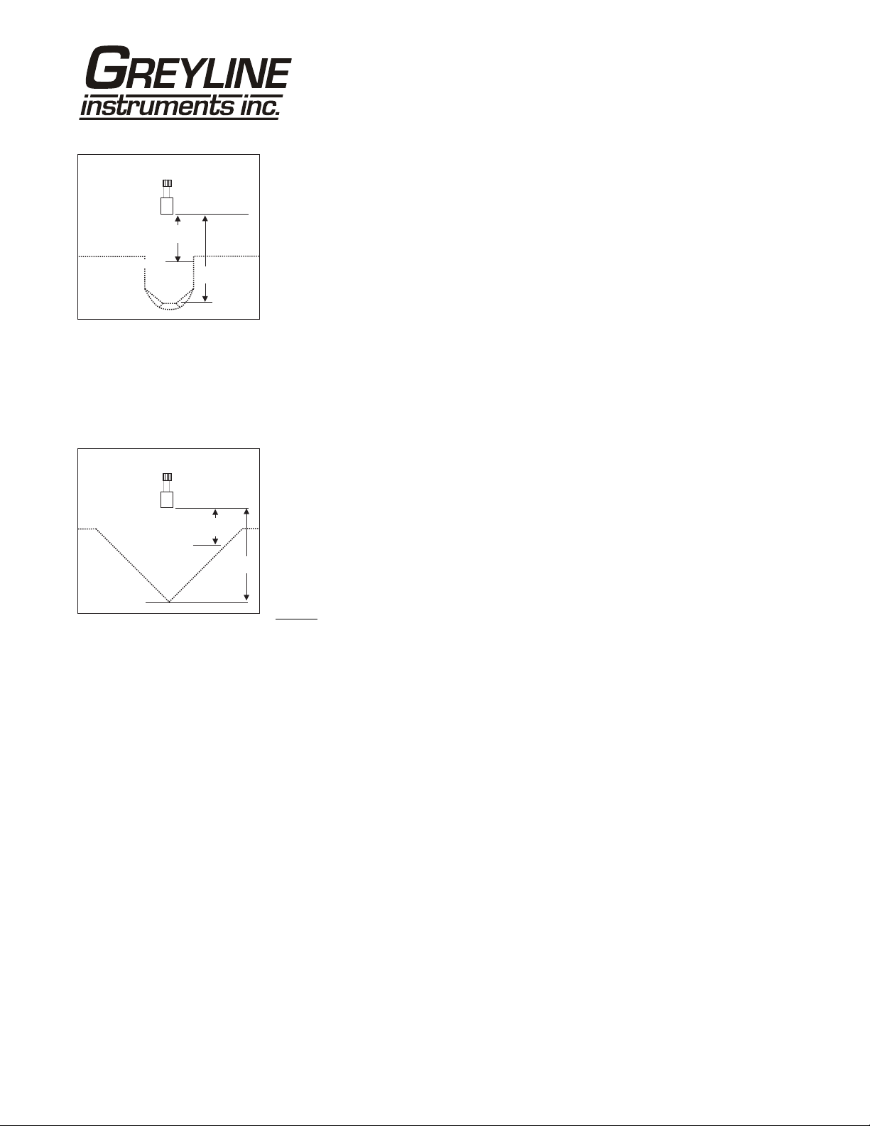
PAL MER BOWLUS
MAX LEVEL
V-NOTCH
ZERO LEVEL
SENSOR
SENSOR
MIN
RANGE
MAX LEVEL
MAX
RANGE
ZERO LEVEL
MIN
RANGE
MAX
RANGE
CALIBRATION
- for Open Channel Flow
1. Before starting the calibration determine:
a) MAX RANGE = ____________________
(Maximum range = distance from the Sensor to Zero flow point)
b) MAX LEVEL = ____________________
(Maximum level of flow through flume or weir)
c) MIN RANGE = __________________
(Distance from sensor to Max Level)
Minimum range = MAX RANGE - MAX LEVEL
(must be at least 8" / 20.3 cm depending on sensor model).
2. Check the maximum range with the sensor installed by:
a) When liquid is at zero level press to view the Range reading in the
Status menu. Use this range measured by the SLT 5.0 as the Max Range
setting.
or
b) Carefully measure distance from sensor to zero level with a tape measure,
and use this measurement as the Max Range setting.
NOTE
: The SLT 5.0 will not detect targets beyond user entered MaxRg.
Page 14
 Loading...