

Page 1

www.greyline.com
USER'S GUIDE
Installation & Operation
Instructions
Pump Station Level Controller
Model PSL 5.0
Manual Series A.1.5
Page 2

Note: This page has been left blank intentionally.
Page 3

PSL 5.0 Pump Station Level Controller
INDEX
CONNECTIONS: ..............................................................................................4
KEYPAD SYSTEM...........................................................................................6
CALIBRATION MENU ....................................................................................7
ICONS................................................................................................................8
MAIN DISPLAY ...............................................................................................9
MESSAGE ICON ..............................................................................................9
STATUS ............................................................................................................9
PASSWORD ....................................................................................................10
UNITS/MODE .................................................................................................11
CALIBRATION ..............................................................................................12
RELAY PARAMETERS .................................................................................14
DATA LOGGING ...........................................................................................16
SPECIAL FUNCTIONS ..................................................................................18
SENSOR MOUNTING/LOCATION ..............................................................19
SENSOR MOUNTING METHODS ...............................................................20
ERROR/WARNING MESSAGES ..................................................................22
FIELD TROUBLESHOOTING ......................................................................23
APPLICATIONS HOTLINE ...........................................................................27
PRODUCT RETURN PROCEDURE .............................................................28
APPENDIX A - OPTIONS ..............................................................................30
CONVERSION GUIDE ..................................................................................38
SPECIFICATIONS ..........................................................................................39
PSL 5.0 RELAY CALIBRATION RECORD .................................................44
IMPORTANT NOTE: This instrument is manufactured and calibrated to meet product specifications.
Please read this manual carefully before installation and operation. Any unauthorized repairs or
modifications may result in a suspension of the warranty.
Available in Adobe Acrobat pdf format
Page 3
Page 4

PSL 5.0 Pump Station Level Controller
CONNECTIONS:
POWER INPUT: The standard model requires AC power input between 100 to 240 VAC 50/60Hz . No
adjustments are necessary for voltages within this range.
Optional DC input model requires 9-32 VDC/9 Watts. Connect to + and - terminals.
Optional Thermostat and Heater modules are available rated for 115 VAC or 230 VAC.
IMPORTANT NOTE: To comply with CSA/UL electrical safety standards, AC power input and relay
connection wires must have conduit entry to the instrument enclosure. Installation requires a switch,
overcurrent fuse or circuit breaker in the building (in close proximity to the equipment) that is marked
as the disconnect switch.
Risk of electric shock. Loosen cover screw to access connections. Only qualified personnel should
!
access connections.
Note: Use of instrumentation over 40°C ambient requires special field wiring.
Note: User replaceable fuse is 2 Amp 250V (T2AL250V).
Page 4
Page 5
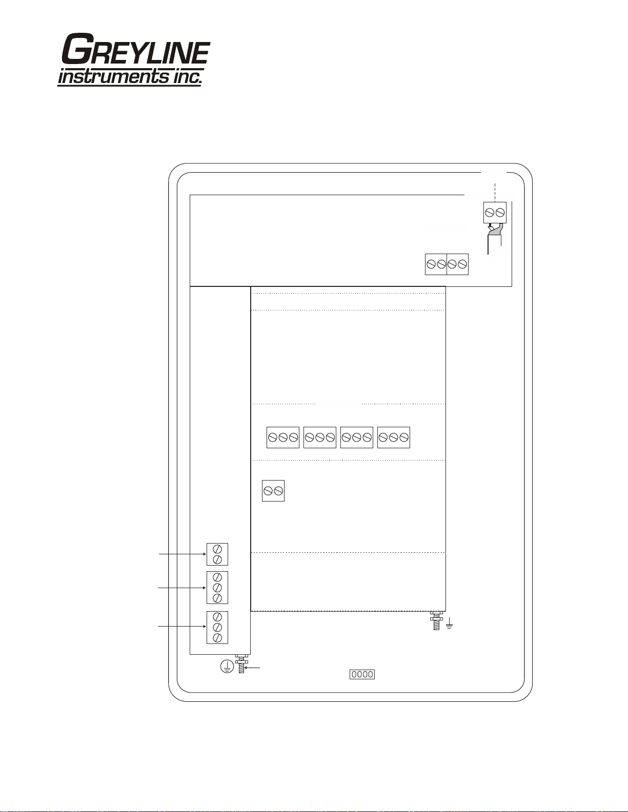
CONNECTIONS
PSL 5.0 Pump Station Level Controller
DATA LOGGER OPTION
PRESSURE
SENSOR
SRC SNK
–
+
–
+
PZ
SENSOR
SHLD
CORE
GRN
WHT
4-20mA
RLY2
RLY1
–
+
NO
C
NC
NO
C
NC
NC
RLY3
AC
LN
AC
GND
RELAYS
NC
C
POWER
INPUT
C
NO
NO
RLY4
HEATER OPTION
USB HARNESS
CONNECTOR
NC
C
RLY5
NC
NO
RLY6
SENSOR
C
NO
GND
Page 5
Page 6

PSL 5.0 Pump Station Level Controller
KEYPAD SYSTEM
The following diagram shows the PSL 5.0 menu system. Arrows show the four directions to leave a
menu box. Pressing a corresponding keypad arrow will move to the next item in the direction shown.
Move the cursor (underline) under numerals and increase or decrease numerals with the and keys.
To store calibration values permanently (even through power interruptions), press the .
Page 6
Page 7

CALIBRATION MENU
144.0inMax Range
Mode} Level
Linear in
Temperature C
--Units/Mode--------
Min Range} 16.00in
--Calibration-------
Damping 10%
PSL 5.0 Pump Station Level Controller
6Relays
24Logger 1. T
1.} 25.00
Utility
Sonar 1.14
--Configuration-----
Analog Out 1
Mode Pump
55.000inOn
YesAlternate
40.000inOff
SLO mode Off
Force Alt 5min
On Delay 5s
Units / Mode}
--Menu Selections----
LevelMode
1Interval 0sec
LoggingLog
2351Set Time 1: :0
Jun 26 12Set Date /20
Log Site ID 0}
--Data Logging-------
Calibration
Relay Parameters
Data Logging
Special Functions
Simulation
--Special Functions-
Configuration
Language English}
Analog Out 4-20mA
Backlight High
Relay LogReset NO
Level 29.02in
4-20mA Level 10.45
Restore Defaults NO
New Password 0000
Relays 1 2 3 4 5 6
--Simulation--------
}Test Actual
LevelFunction
SsLO Time 30
Relay 1}
--Relay Parameters--
BSensor Good
Data log Stopped
Log Used 0%
Sensor A Good
--Message-----------
Temperature 21C
Password 0000
--Password----------
R1 0.12hr
R2 .05hr0
R3 0.32hr
R4 0.50hr
R5 1.09hr
R6 0.51hr
-- ----Relay Run Times
in
Sensor B 0.13hr
29.055
Relays 1 2 3 4 5 6
29.056inMaximum
29.016inMinimum
29.036inAverage
12:32:00Max Time
12:33:00Min Time
Range} A 50.98in
Range B 47.83in
EC 100%
Relays 1 2 3 4 5 6
--Status------------
Date Feb. 12/20} 10
--24 hr log----------
Page 7
Page 8

ICONS
PSL 5.0 Pump Station Level Controller
1. 2.
1.
1.
2.
2. 3.
4.
Message waiting. Press .Ç
Data logging .off
Data logging .on
USB file download.
File download completed.
Download Error.
1.
1.
2.
2.
3.
3.
Echo OK.
No Echo .
Measurement switched to pressure sensor.
Page 8
Page 9

PSL 5.0 Pump Station Level Controller
29.055
Relays 1 2 3 4 5 6
--Message----------Data log Stopped
Log Used 0%
Sensor A Good
Sensor B Good
Temperature 21C
--Status------------
Range A 50.98in
}
Range B 47.83in
EC 100%
Relays 1 2 3 4 5 6
--Relay Run Times---R1 0.12hr
R2 0.05hr
R3 0.32hr
R4 0.50hr
R5 1.09hr
R6 0.51hr
Sensor B 0.13hr
in
MAIN DISP LAY
The main display shows the units selected from the Units/Mode menu, Level or
Range being measured and RELAY states.
MESSAGE ICON
Press from the MAIN display to view status of the data logger and
error/warning messages provided by the instrument. The Message icon will
blink on the MAIN display if error messages are being generated by the
instrument. Refer to the manual section Error/Warning Messages for a
description. Press to return to the main display.
STATUS
Press from the MAIN display to view instrument status. Range will be
displayed in linear units, for both the sonar and pressure sensors.
Range A Range measurement of PZ transducer.
Range B Equivalent range measurement of pressure transducer.
EC Displays echo confidence.
Relays Energized relays will display as a white character on a black
background.
RELAY RUN TIMES
Tracks run times of the six relays. Also indicates total down time of the ultrasonic
transducer.
Page 9
Page 10
PSL 5.0 Pump Station Level Controller
--Password----------
Password 0000
PASSWORD
The password (a number from 0000 to 9999) prevents unauthorized access to the
Calibration menu.
From the Main display press the key to get to
password is 0000 and if it has not been changed press the to proceed to the
Menu Selections screen.
If a password is required, press to place the cursor under the first digit and or
to set the number, then to the second digit, etc. Press or to proceed to
the Menu Selections screen.
A new password can be stored by going to
Password
.
Password. Factory default
Special Functions/New
Page 10
Page 11
PSL 5.0 Pump Station Level Controller
--Units/Mode--------
Mode Level
}
Linear in
Temperature C
--Units/Mode--------
Temperature C
}
UNITS/MODE
From
Range.
Mode press the and then the or to select Level or
Range mode displays distance from the sensor to the target or liquid surface
like a tape measure. Range mode is useful to measure the exact
distance from the sensor to the zero level during calibration, or to
monitor "outage" or free space in a tank.
Level mode can be used to measure tank level in linear units.
Press the to store your selection then the to the next menu item and to
enter.
Linear
press the key and then the or to select your units
of measurement. Press the to store your selection.
Temperature
press and then or to select C or F
(Centigrade or Fahrenheit).
F
Press or to return to the Menu Selections screen.
Page 11
Page 12

PSL 5.0 Pump Station Level Controller
--Calibration-------
Min Range 8.000in
}
Max Range 80.000in
Damping 10%
LOS Time 30s
CALIBRATION
Press the to
Calibration and to enter. Use or to position
before each menu item and to enter. When settings are completed press to
store and return to the Calibration menu.
Min Range Distance from the sensor face to highest expected level.
Max Range Distance from sensor to Zero level.
Damping Minimum damping allows fast response to level changes.
Increasing damping slows the PSL 5.0's response to level changes
and is ideal to smooth the display and outputs in turbulent
conditions. Damping value is shown in percent (0-99%). Some
experimentation may be required to select the optimum damping
value. A value of 1% is recommended for most applications. For
fast level changes (up to ½ inch/sec - 13 mm/sec), a Damping
value of 1% is recommended.
LOS Time Press and or to change the number of seconds without
receiving a level measurement from either the PZ or pressure
sensor before the PSL 5.0 displays ECHO LOSS, and Control
relays change state as calibrated under Relay Parameters.
Factory default is 30 seconds and is recommended for most
applications. Minimum is 1 second and maximum is 99 seconds.
Press from the
Units/Mode display to return to Menu Selections.
Page 12
Page 13
PSL 5.0 Pump Station Level Controller
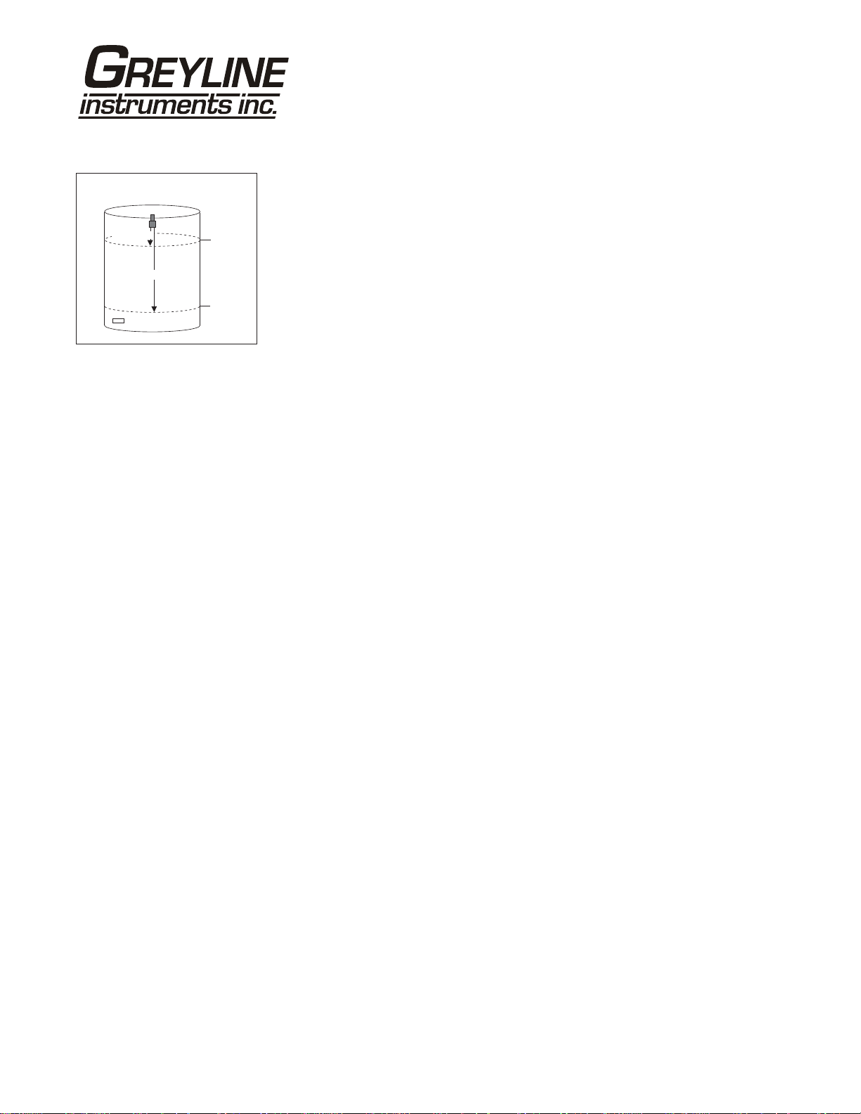
INSTALLATION
IN WELL
MIN RANGE
PZ SENSOR
MAX LEVEL
CALIBRATION
Calibrate the PZ Sensor for Level Measurement
1. Before starting the calibration determine:
a) MAX RANGE = ________________
MAX RANGE
(Maximum range = distance from Sensor to Zero level)
4-20 mA input
sensor (pressure)
ZERO LEVEL
b) MAX LEVEL = ________________
(Maximum level of product being measured)
c) MIN RANGE = ________________
(Distance from sensor to Max Level)
Minimum range = MAX RANGE - MAX LEVEL
(must be at least 8" / 203 mm depending on sensor model)
2. Check the maximum range with the sensor installed by:
a) When liquid is at zero level press to view the Range reading in the
Status menu. Use this range measured by the PSL 5.0 as the Max Range
setting.
or
b) Carefully measure distance from sensor to zero level with a tape measure,
and use this measurement as the Max Range setting.
Redundant 4-20mA input (pressure) Sensor Installation and SelfCalibration
1. Install the redundant 4-20mA input sensor near the bottom of the well
according to manufacturer’s instructions and below the zero level.
2. Ensure that the PSL 5.0 with PZ sensor has been properly calibrated to
measure water level and is functioning properly.
3. Connect the 4-20mA redundant sensor to the PSL 5.0 SRC terminals when
the transmitter is loop-powered (24VDC power provided by the PSL 5.0) or
to SNC terminals when the 4-20mA transmitter is powered from another
source.
4. Operate the PSL 5.0 through several pump cycles to allow the 4-20mA input
sensor to self-calibrate.
5. Note: When 4-20mA input sensor has completed self-calibration the Message
window will indicate that Sensor B status is Good.
Page 13
Page 14

PSL 5.0 Pump Station Level Controller
--Relay Parameters-Relay 1
}
Function Level
Mode Pump
On 55.000in
Off 40.000in
LOS mode Off
Alternate Yes
Force Alt 5min
On Delay 5s
RELAY PARAMETERS
Relay Press and or to select a corresponding relay number (6
relays are standard).
Function Press or to select Off, Range, or Level.
Level Press to Mode and to select
Pump, Low Alarm or Hi Alarm.
Note:
Function setting Level will change according to selections made
under
Units/Mode eg Level or Range,
Press to return to
Menu Selections.
LOS mode Set the desired relay condition in the case that PSL cannot
obtain a level measurement or set relay to provide a LOS
alarm:
Off Sets Relay state to Off if PSL cannot obtain
level reading.
On Sets Relay state to On if PSL cannot obtain
level reading.
Hold Holds relay state if PSL cannot obtain level
reading.
Sensor B Acts as PZ sensor signal loss alarm when
Pump On and Off set to the same level.
Alarm will indicate whenever PSL is
operating off of the redundant 4-20mA
input (pressure) sensor.
Sen B Fault Acts as 4-20mA input sensor fault alarm
when Pump On and Off set to the same
level. Alarm will indicate fault of the 420mA input sensor.
Page 14
Page 15

PSL 5.0 Pump Station Level Controller
Alternate Up to six pumps/relays can be set to alternate when in pump
mode. Following the end of a pump cycle pumps will swap
ON and OFF relay settings.
PUMP ALTERNATION (R1, R2, R3)
LEAD
PUMP
1st CYCLE
2nd CYCLE
3rd CYCLE
1
2
3
...ETC
LAG
PUMP 1
2
3
1
LAG
PUMP 2
3
1
2
ON
LAG
PUMP 2
OFF
ON
LAG
PUMP 1
OFF
SENSOR
ON
LEAD
PUMP
OFF
Note: Alternating pumps must have different On setpoints to
alternate correctly, otherwise alternating pumps will turn On at
the same time.
Force Alt Set time for forced alternation. PSL will automatically trigger
pump alternation if time expires over a longer pump cycle.
On Delay Set On Delay to invoke a delay between simultaneous changes
to pump states.
Page 15
Page 16

PSL 5.0 Pump Station Level Controller
--Data Logging------Log Site ID 00
}
Mode Level
Set Date Feb 18/2008
Set Time 11:27:40
Interval 10sec
Log Start
Mar 19/2009
12:28:41
99
Range
60min
30min
15min
10min
5min
2min
1min
30sec
Stop
Delete
DATA LOGGING
Setup
Select Data Logging from Menu Selections.
Log Site ID
Enter a number from 00 to 99. The site ID will
become part of the downloaded file name to help
distinguish downloads from different instruments. Press
to store the setting.
Mode
Select Level or Range. Press to store the
setting.
Set Date
Press or to scroll and select Month, Day and Year.
Press to store the setting.
Set Time
Press or to select the current time in Hours, Minutes
and Seconds. Press to store the setting.
Interval
Press or to select the logging interval.
Press to store the setting.
Log
, Start or Delete the log file.
Stop
Press or to
Press or to
Delete and to delete the log file.
Start and to start the logger.
Note:
You MUST delete old log and start a new log AFTER having set
changes to
Log Site ID, Mode and/or Interval for those
changes to be applied to the log file.
RETRIEVE LOG FILE
Plug a USB Flash Memory Drive (not supplied by Greyline) into the USB output
cable from the instrument. The instrument display will show the USB file
download icon until the log file is transferred to the memory card and then display
file download completed icon. The USB flash drive may be removed.
Download file names will appear in this format:
PSL_ _00A.LOG
MODEL TAG DOWNLOAD
Tag is set according to the Log Site ID entered in the instrument Data Logging
menu.
Page 16
Page 17

PSL 5.0 Pump Station Level Controller
Download letter will be A for the first download from an instrument. B for the
second, then C etc. At the letter Z a - character will appear indicating that the
maximum number of downloads for that instrument are on the USB flash drive.
Older files can be erased or moved from the flash memory drive or a new memory
drive can be used.
OPENING LOG FILES
Install Greyline Logger on your PC or laptop. Refer to the Help menu in the
program for detailed instructions.
Select File/Open/Instrument Log (.log) to open the log file from your USB flash
drive.
Page 17
Page 18

PSL 5.0 Pump Station Level Controller
--Special FunctionsLanguage English
}
Analog Out 4-20mA
Backlight High
Reset Relay Log NO
Restore Defaults NO
New Password 0000
--Special Functions-
Language English
Backlight Hig
} h
Medium
Low
Key Hi/Lo
Key High
Key Med
Key Low
Off
SPECIAL FUNCTIONS
Language Select English, French or Spanish
and press .
Analog Out Select 4-20mA or 0-5V mode for the analog output.
Backlight
Select High, Medium or Low for continuous
backlight.
Select
after a keypress and then
Key Hi/Lo for high backlight for 1 minute
Lo backlight until a key
is pressed again.
Select
Key High, Med or Low for backlight
for 1 minute after a keypress and then backlight off
until a key is pressed again.
Reset Relay Log Select Yes and press to erase Relay Runtime log.
Restore Defaults Select Yes and press to erase all user settings
and return the instrument to factory default settings
New Password Select any number from 0000 to 9999 and press .
Default setting of 0000 will allow direct access to the
calibration menus. Setting of any password greater
than 0000 will require the password to be entered to
access the calibration menus.
Press to return to
Menu Selections.
--Simulation-------Test Actual
}
Range 8.00in
4-20mARange 4.00
Relays 1 2 3 4 5 6
SIMULATION
Exercises the 4-20mA (0-5V) output, digital display and control relays.
Test Select Maximum and press to simulate maximum Range or Level
and to output 20mA (5V) to the analog channel.
Select
Minimum and press to simulate minimum Range or Level
and to output 4mA (0V) to the analog channel.
To simulate an intermediate Range or Level set
and then enter a value for the
and control relays will respond to the simulated value.
Page 18
Test to Actual
Range or Level. The analog output
Page 19

PSL 5.0 Pump Station Level Controller
SENSOR MOUNTING/LOCATION
- Tank Level/Inventory Applications
Each PSL 5.0 Level Transmitter includes a noncontacting ultrasonic sensor. The sensor must be
installed in a position to obtain unobstructed echoes
from the liquid or material being measured.
Mount the sensor away from pipes, ladders, or
structural members which might cause continuous false
echoes.
BAD GOOD
90°
Page 19
Page 20

SENSOR MOUNTING METHODS
Notes:
1. Use the ¾" NPT "Isolation
Coupling" supplied and
only. Do not clamp sensor
tighten
body or stem.
2. Locate the sensor 1 ft (30 cm) from
the sidewall or obstruction for every
10 ft (3 m) depth.
3. mount in direct sunlight.
Do not
4. Extend sensor cableupto500 ft
(150 m) with RG62AU coaxial only.
CROSS BAR MOUNT
CLAMP
DO NOT
CLAMP IN
THIS AREA
hand
3/4"
CONDUIT
ISOLATION
COUPLING
(SUPPLIED)
MUST BE
USED
FLANGE MOUNT
4" OR 6" BLIND FLANGE
TAPPED ¾" NPT
¾" NPT
NIPPLE
DO NOT
CLAMP IN
THIS AREA
PSL 5.0 Pump Station Level Controller
FLEXIBLE
CONDUIT
JUNCTION
BOX
(OPTION JB)
ISOLATION
COUPLING
(SUPPLIED)
MUST BE
USED
CONDUIT MOUNT
3/4"
CONDUIT
STANDPIPE LENGTH
AS SHORT AS POSSIBLE
STANDPIPE DIAMETER
AS LARGE AS POSSIBLE
TYPICAL STANDPIPE:
4” / 100 mm DIAMETER
12”/300 mm LENGTH
NARROW DIAMETER
STANDPIPES (<4” / 100 mm)
MAY AFFECT ACCURACY
OF READING
STAND PIPE MOUNT
SMOOTH
GRIND OR FILE
PIPE EDGE
DO NOT
CLAMP IN
THIS AREA
3/4" NPT
DO NOT
CLAMP IN
THIS AREA
ISOLATION
COUPLING
(SUPPLIED)
MUST BE
USED
ANGLE MOUNT
NIPPLE
ISOLATION
COUPLING
(SUPPLIED)
MUST BE
USED
Page 20
Page 21

PSL 5.0 Pump Station Level Controller
ENCLOSURE INSTALLATION
Locate the enclosure within 20 ft (6 m) of the sensor (500 ft -150 m optional). The enclosure can be wall
mounted with the four mounting screws (included) or panel mounted with Option PM Panel Mount kit
from Greyline Instruments.
Avoid mounting the enclosure in direct sunlight to protect the electronics from damage due to
overheating and condensate. In high humidity atmospheres, or where temperatures fall below freezing,
Option TH Enclosure Heater and Thermostat is recommended. Seal conduit entries to prevent moisture
from entering enclosure.
NEMA4X (IP66) WITH CLEAR COVER
1. Open hinged enclosure cover.
COVER
2. Insert #8 screws (supplied) through the four enclosure mounting holes
to secure the enclosure to the wall or mounting stand.
Additional conduit holes can be cut in the bottom of the enclosure when
ENCLOSURE
MOUNTING
HOLES
required. Use a hole saw or Greenlee-type hole cutter to cut the required
holes.
DO NOT make conduit/wiring entries into the top of the enclosure.
ENCLOSURE
END VIEW
Note: This non-metallic enclosure does not automatically provide grounding between conduit
connections. Grounding must be provided as part of the installation. Ground in accordance with the
requirements of the National Electrical Code. System grounding is provided by connecting grounding
wires from all conduit entries to the steel mounting plate or another point which provides continuity.
CLEANING
Cleaning is not required as a part of normal maintenance.
Page 21
Page 22

ERROR/WARNING MESSAGES
PSL 5.0 Pump Station Level Controller
ECHO LOSS
No valid echoes received within the LOE TIME setting. The PSL 5.0 will
hold the display and outputs at the last reading until a new echo is received. If
a redundant level sensor is connected the PSL 5.0 will seamlessly switch to
the second sensor without an echo loss error message.
- or -
Your choice of Units exceeds 9,999,999. Use USMG/d, IMG/d or
m3/d so that Units will be 9,999,999 or less
ECHO TOO CLOSE
Indicates that the target is less than Min Range distance from the sensor
(too close to the sensor).
SENSOR A OPEN
Instrument has detected PZ sensor connection/cable Open.
SENSOR A SHORTED
Instrument has detected PZ sensor connection/cable Shorted.
SENSOR B Check Sensor
Instrument has detected invalid measurement from redundant 4-20mA input
(pressure) sensor or that sensor is not connected.
SENSOR B Not tracking
Usually indicates that 4-20mA input sensor is not yet self-calibrated or may
indicate temporary discrepancy in level measurement between the two
sensors.
Page 22
Page 23

PSL 5.0 Pump Station Level Controller
FIELD TROUBLESHOOTING
SYMPTOMS
Display - full scale A
- zero B
- erratic - random C
- drifting up D
- drifting down E
ECHO LOSS prompt - flashing F
Calibration Non-Linear H
SYMPTOMS
Unit “See’s” Wrong Target Due To:
A - sensor cover not removed - remove protective cover after installation
A,C,D,F - sensor not aimed correctly
A,D,F - dust/dirt buildup on sensor - clean carefully (do not scratch sensor face)
A,D,F - condensation on sensor - lower Sensor
A,D - sensor mounting stand pipe
C,E - very turbulent level in tank - increase
Unit Picks-Up Interference Due To:
A,C - noise from high pressure fill - install submerged fill pipe
A,D - sensor coupling over tightened - hand tighten only (like a light bulb)
A,D - sensor coupling not used - use coupling supplied
C - other ultrasonic unit in close proximity - relocate the other ultrasonic sensor or install a
Electrical interference:
C - sensor cable connections reversed
C - through sensor cable - use properly grounded metal conduit
FAULTS SOLUTIONS
- too long / - too narrow
- dirty / - gasket intruding
CHECK
- insulate sensor mounting location
- increase
menu) by 1-3” / 2.5-7.5 cm
- wipe sensor face and body with Rain-X
- lower Sensor below stand pipe intrusion
- change tank fill method
redundant 4-20mA level sensor
Min Range (CALIBRATION
Damping (CALIBRATION menu)
Page 23
Page 24

PSL 5.0 Pump Station Level Controller
C - sensor cable extended and junction not
insulated
C - through enclosure - use metal enclosure
C - through 4-20mA output cable - use shielded twisted pair (shielded to AC ground)
C - wiring or installation close to variable
speed drive or inverter
Unit Receives No Return Echo Due To:
C,F,E - foam on liquid surface - locate ultrasonic sensor as low as possible in the
B - target beyond
F - sensor damaged - remove sensor from mounting and aim at a flat,
F - sensor misalignment - check with a level
Wiring Problems Due To Sensor Cable:
A,C,F, - open circuit
B,F - short circuit - check connections/continuity (8850 ohms min.)
F - too long (max 500 ft., 150 m)
C - bundled/run in conduit with power cable
C - sensor ground shorted to conduit/enclosure
A - extended with wrong type of wire - use RG62A/U coaxial only
C - close to high voltage/large motors
C - AC chassis/ground missing on instrument
power connections
Non-Linearity Due To:
H - vapour - dissipate fumes, Calibration in-situ
H - zero not set accurately - see “Zero Positioning of Sensor”
H - temperature measurement inaccuracy - install sensor sunscreen
Max Range - recalibrate
- Use metal Junction Box
- use grounded metal conduit
- follow V.S.D. manufacturer’s instructions for Drive
grounding, wiring and shielding
wet well and above an area where foam is less
present
- install a redundant 4-20mA level sensor
stable target to test
- check connections/continuity (8850 to 12700 ohms
max./-30°C to +70°C )
- insulate
- mount sensor closer to maximum water level
Page 24
Page 25

PSL 5.0 Pump Station Level Controller
PZxx Series Sensors
Troubleshooting
Resistance measured (between the shield and center wire) across the coaxial cable ends by mulitmeter
indicates ambient temperature.
Resistance vs. Temperature
Page 25
Page 26

FUSE REPLACEMENT
1. Turn OFF power.
2. Loosen cover screw and open.
3. Remove power module.
4. Locate fuse on Power Board.
5. Replace fuse with 2 AMP/ 250V, 5 x 20mm fuse.
6. Reinstall power module into chassis.
PSL 5.0 Pump Station Level Controller
Fuse
POWER MODULE
Page 26
Page 27

PSL 5.0 Pump Station Level Controller
APPLICATIONS HOTLINE
For applications assistance, advice or information on any Greyline Instrument contact your Sales
Representative, write to Greyline or phone the Applications Hotline below:
United States: Tel: 315-788-9500 Fax: 315-764-0419
Canada: Tel: 613-938-8956 Fax: 613-938-4857
Toll Free: 888-473-9546
Email: info@greyline.com
Web Site: www.greyline.com
Greyline Instruments Inc.
Canada USA:
16456 Sixsmith Drive 105 Water Street
Long Sault, Ont. K0C 1P0 Massena, NY 13662
Page 27
Page 28

PSL 5.0 Pump Station Level Controller
PRODUCT RETURN PROCEDURE
Instruments may be returned to Greyline for service or warranty repair.
1) Obtain an RMA Number from Greyline -
Before shipping a product to the factory please contact Greyline by telephone, fax or email to obtain an
RMA number (Returned Merchandise Authorization). This ensures fast service and correct billing or
credit.
When you contact Greyline please have the following information available:
1. Model number / Software Version
2. Serial number
3. Date of Purchase
4. Reason for return (description of fault or modification required)
5. Your name, company name, address and phone number
2) Clean the Sensor/Product -
Important: unclean products will not be serviced and will be returned to the sender at their expense.
1. Rinse sensor and cable to remove debris.
2. If the sensor has been exposed to sewage, immerse both sensor and cable in a solution of 1 part
household bleach (Javex, Clorox etc.) to 20 parts water for 5 minutes. Important: do not immerse open
end of sensor cable.
3. Dry with paper towels and pack sensor and cable in a sealed plastic bag.
4. Wipe the outside of the enclosure to remove dirt or deposits.
5. Return to Greyline for service.
3) Ship to Greyline -
After obtaining an RMA number please ship the product to the appropriate address below:
Canadian and International USA
Customers: Customers:
Greyline Instruments Inc. Greyline Instruments Inc.
16456 Sixsmith Drive 204 150th Avenue
Long Sault, Ont. K0C 1P0 Madeira Beach, FL 33708
RMA# RMA#
Page 28
Page 29

LIMITED WARRANTY
_____________________________________
Greyline Instruments warrants, to the original purchaser, its
products to be free from defects in material and workmanship for a
period of one year from date of invoice. Greyline will replace or
repair, free of charge, any Greyline product if it has been proven to
be defective within the warranty period. This warranty does not
cover any expenses incurred in the removal and re-installation of
the product.
PSL 5.0 Pump Station Level Controller
If a product manufactured by Greyline should prove defective
within the first year, return it freight prepaid to Greyline
Instruments along with a copy of your invoice.
This warranty does not cover damages due to improper installation
or handling, acts of nature, or unauthorized service. Modifications
to or tampering with any part shall void this warranty. This
warranty does not cover any equipment used in connection with the
product or consequential damages due to a defect in the product.
All implied warranties are limited to the duration of this warranty.
This is the complete warranty by Greyline and no other warranty is
valid against Greyline. Some states do not allow limitations on how
long an implied warranty lasts or limitation of incidental or
consequential damages, so the above limitations or exclusions may
not apply to you.
This warranty gives you specific legal rights, and you may also
have other rights which vary from state to state.
Greyline Instruments Inc.
Page 29
Page 30

PSL 5.0 Pump Station Level Controller
APPENDIX A - OPTIONS
EXTRA SENSOR CABLE - OPTION XC
Each Greyline level instrument includes 25 ft. (7.6 m) RG62AU coaxial cable. Additional RG62AU
coaxial cable and Cable Junction Box (Option JB2X) may be installed to extend cable up to 500 ft
(152m) as required during installation. No adjustment is required when the sensor cable is extended or
shortened. Use only RG62AU (or RG62U) coaxial cable which is available from Greyline Instruments
or your local distributor. Nominal impedance of RG62AU cable is 93 ohms.
Extended sensor cable maybe installed in metal or plastic conduit. Recommended installation with a
junction box is illustrated below:
CORE
SHIELD
EXTENDED SENSOR CABLETO
ELECTRONICS ENCLOSURE
- MAX.TOTAL CABLE LENGTH
500 ft (152m) RG62AU coaxial
- CONDUIT RECOMMENDED FOR
MECHANICAL PROTECTION
TO SENSOR
RG62AU COAXIAL
CORE
SHIELD
JUNCTION BOX - OPTION JB2X
NEMA4X (IP66) polycarbonate Junction Box with terminal strips is available from Greyline
Instruments. Includes compression fittings for watertight coaxial cable entries.
90 mm / 3.54"
57 mm / 2.24"
3.9 mm
0.15"
MOUNTING
HOLES (X4)
JB2X
DIMENSIONS
TOP VIEW
END VIEW
90 mm / 3.54"
60 mm / 2.36"
Page 30
Page 31

PSL 5.0 Pump Station Level Controller
EXTENDED SENSOR CABLE INSTALLATION IN MANHOLE
MANHOLE COVER
JBX
ULTRASONIC
SENSOR
XC EXTENDED
SENSOR CABLE
UP TO 500 ft 152 m
CONDUIT TO
ELECTRONICS
Wetwell, Sump or Pump Station
Page 31
Page 32

PSL 5.0 Pump Station Level Controller
SENSOR INTRINSIC SAFETY
(OPTION ISB)
When connected through Intrinsic Safety Barriers, Greyline PZ** Series sensors are certified for
installation in a hazardous location rated:
Class I, Groups C,D
Class II, Groups E,F,G
Class III
The Intrinsic Safety Barrier may be ordered with the Greyline instrument and is supplied mounted in the
Greyline instrument enclosure. Replacement barrier fuses (Part No. ISB- 011239) may be purchased
separately. The instrument enclosure containing the ISB Intrinsic Safety Barrier must be installed in a
non-hazardous location.
Page 32
Page 33

GN3SPEC-ISB-03
The intrinsic safety barrier
assemblies installed in the
OCF 5.0/SLT 5.0/PSL 5.0
limit the voltage and current
supplied to the transducers
to the values listed under
‘Barrier Specifications’. To
safely install a Greyline
transducer certified for use in
hazardous locations you
must refer to the installation
drawings/specifications of
the certified transducer.
PSL 5.0 Pump Station Level Controller
2
1
s)
BARRIER SPECIFICATIONS
STAHL BARRIER
System Parameters
OCF 5.0/SLT 5.0/PSL 5.0
Installed in
Non-Hazardous Location
STAHL 9001/02-093-390-101
3
TRANSDUCER
GND
TRANSDUCER
CONNECTIONS
Entity Parameters
(rated 9.6V, 27 ohm
4
V
9.3V
9001/02-093-390-101
9.6V, 27 ohms
m
U
250V
Page 33
0C
I
SC
390mA
P
0
906.8mW
C
a
4.1µF
a
L
0.16mH
Page 34

GN3SPEC-ISB-05
The intrinsic safety barrier
assemblies installed in the
PSL 5.0 limit the voltage and
current supplied to the
transducers to the values
listed under ‘Barrier
Specifications’. To safely
install a Greyline transducer
certified for use in hazardous
locations and a 4-20mA
pressure transducer certified
for use in hazardous
locations you must refer to
the installation
drawings/specifications of
the certified transducers.
PSL 5.0 Pump Station Level Controller
2
2
1
1
s)
BARRIER SPECIFICATIONS
STAHL BARRIER
System Parameters
PSL 5.0
Installed in
Non-Hazardous Location
3
TRANSDUCER
GND
TRANSDUCER
CONNECTIONS
Entity Parameters
(rated 9.6V, 27 ohm
STAHL 9001/02-093-390-101
STAHL 9001/0 - - -1011 280 110
4
4
3
9001/02-093-390-101
9001/01-280-110-101
9.6V, 27 ohms
-
m
U
250V
250V
V
9.3V
28V
Page 34
0C
SC
I
390mA
110mA
0
P
906.8mW
770mW
a
C
4.1µF
0.083µF
a
L
0.16mH
1.2mH
Page 35

PSL 5.0 Pump Station Level Controller
ENCLOSURE HEATER AND THERMOSTAT - Option TH
Instruments can be factory-equipped with an Enclosure Heater and Thermostat or the module can be
customer-installed. The Thermostat is factory set to turn ON at 40°F (4.5°C) and OFF at 60°F (15.5°C).
Power consumption is 15 Watts.
TO AC POWER SUPPLY
ENCLOSURE SUNSCREEN - Option SCR
Do not mount instrument electronics in direct sunlight. Overheating will reduce the life of electronic
components and condensate may form during the heat/cool cycles and cause electrical shorts.
11"/280 mm
Note:
Exposure to direct sunlight can cause
overheating and moisture condensation
which will reduce the operating life of
electronics.
Protect Instruments from direct sunlight
with this iridite finished aluminum sun
screen (Greyline Option SCR).
Seal conduit entries with caulking
compound to further reduce moisture
condensation.
11"
280 mm
5"
127 mm
Page 35
Page 36

PSL 5.0 Pump Station Level Controller
POWER INPUT OPTION
9-32VDC
PSL 5.0 Level Monitors may be ordered factory-configured for 9-32VDC power input.
QUICK BENCH TEST:
Connect Sensor as shown below, then Power. When properly connected figures will show on the large
LCD display. Test operation of the PSL 5.0 by holding the sensor steadily and aiming at a flat, stable
target 16 to 48" (400 to 1200 mm) away from the end of the sensor. Allow a few seconds for the PSL
5.0 to lock onto the target before displaying its distance. The PSL 5.0 will now display Range in ft or cm
(factory calibration).
CONNECTIONS:
POWER INPUT: Connect 9-32VDC/0.5 Amps to the + and - terminals. The Power Input GND must be
connected to the nearest Ground pole. A 1 amp fuse in line is recommended.
PZ
SENSOR
SHLD
CORE
GRN
WHT
PRESSURE
SENSOR
SRC SNK
–
–
+
+
DATA LOGGER OPTION
RELAYS
NC
NC
4-20mA
RLY2
RLY1
NO
C
NC
NO
C
NC
C
RLY3
DC
+–
–
+
DC
GND
NO
C
RLY4
NC
C
NO
NO
RLY5
RLY6
USB HARNESS
CONNECTOR
NC
C
NO
SENSOR
GND
Page 36
Page 37

PSL 5.0 Pump Station Level Controller
APPENDIX B - APPLICATIONS BACKGROUND
Conditions in the tank or channel where the ultrasonic sensor is installed can affect the performance,
range and accuracy of the system. The following notes are for general reference. Contact Greyline
Instruments or your local representative for specific information on your application.
FOAM - Solid or dense surfaces such as a smooth liquid surface will give the best echos in an ultrasonic
level measuring system. Foam acts as a sound insulator and may eliminate, or reduce the strength of an
echo. Measurement range may be reduced in a system where foam is present. Ultrasonics are not
recommended where thick dense foam is continually present. Thin layers of light foam (½ in. or less)
can generally be disregarded. Use a stilling well in open channel applications.
LIQUIDS - The PSL is ideal to monitor tank liquid level or inventory. Caustic, corrosive or very viscous
liquids can be monitored without contacting the liquid.
SOLIDS - The PSL will measure most granular material and powders as well as liquids. Powders will
not generally provide the same echo strength as liquids. Therefore maximum expected range should be
reduced to approximately 20 feet (6 m) for powders. There are many exceptions to this rule and
installation of a test system is recommended when in doubt.
DUST - Any obstructions to the sound will affect performance of the system. In silo’s where heavy
concentrations of dust are expected ultrasonics may not work. Where moderate dust is encountered care
should be taken to mount the sensor in a position where dust accumulation will be minimized and where
the sensor can be cleaned if necessary.
SENSOR TEMPERATURE - The standard sensor model PZ34 supplied with each Pump Station Level
Controller includes a built-in temperature sensor. The PSL automatically compensates for temperature
fluctuations to retain high accuracy. Note the operating temperature ranges listed in the product
specifications section. Do not exceed the sensor temperature ratings or damage may occur.
ELECTRONICS TEMPERATURE - Note operating temperature ranges listed in the product
specifications. Temperatures higher than the maximum shown can reduce the operating life of the
electronics. Moisture condensation from those temperatures below the range shown can also damage
electronics components. In cold or outdoor environments the optional factory-installed enclosure heater
and thermostat is recommended.
NOISE - Because the PSL’s sensor operates at high sound frequency, regular process noise or vibration
will not affect the system. Sensors installed in close proximity to one another in the same tank may
“cross-talk” and should be synchronized.
VAPOUR - May affect but it can be compensated for by calibration in-situ. Severe vapour stratification
can cause false echoes. Variable vapour cannot be compensated.
CHEMICAL COMPATIBILITY - The PSL’s Sensor is constructed of very durable materials with broad
compatibilities. Tank contents should be checked for their compatibility with PVC. An all-teflon sensor
is available for corrosive applications.
Page 37
Page 38

PSL 5.0 Pump Station Level Controller
CONVERSION GUIDE
FROM TO MULTIPLY BY
US GALLONS CUBIC FEET 0.1337
US GALLONS IMPERIAL GALS 0.8327
US GALLONS LITRES 3.785
US GALLONS CUBIC METERS 0.003785
LITRES/SEC GPM 15.85
LITRES CUBIC METERS 0.001
BARRELS US GALLONS 42
BARRELS IMPERIAL GALS 34.9726
BARRELS LITRES 158.9886
INCHES MM 25.4
DEGREES F DEGREES C (°F-32) x 0.556
POUNDS KILOGRAMS 0.453
PSI BAR 0.0676
FOOT² METER² 0.0929
VOLUME CALCULATION FOR ROUND TANKS: 3.142 x R² x H
R = TANK RADIUS (½ TANK DIAMETER)
H = TANK HEIGHT
Page 38
Page 39

PSL 5.0 Pump Station Level Controller
SPECIFICATIONS
7.4 / 188 mm"
6.46 / 164 mm"
5.12 / 130 mm"
Accuracy: ±0.25% of Range or 2
mm, whichever is
greater
Repeatability and
Linearity: 0.1% F.S.,
Displays: White, backlit matrix -
displays level, relay
states, operating mode
and calibration menu
Calibration: built-in 5-key calibrator
PSL 5.0
Pump Station
Level Controller
10 / 254 mm"
10.94" / 278 mm
with English, French or
Spanish language
selection
Power Input: 100-240VAC, 50/60Hz,
CONDUIT ENTRY
LOCATION
SIDE VIEW
30 Watts or
9-32VDC, 9 Watts max
Output: Isolated 4-20mA (1000 ohm load max.)
Control Relays: Qty 6, rated 5 amp 240VAC SPDT, programmable pump control and
alternation, level/status alarm
Enclosure: watertight, dust tight NEMA4X (IP 66) polycarbonate with a clear
shatter-proof face
Environmental Conditions: Relative humidity up to 80% -23 to 60°C ambient temperature,
maximum 5000 m altitude, pollution degree 4, Installation Category II.
Sensitivity: adjustable. Damping: adjustable
Electrical Surge Protection: Sensor, 4-20mA output and AC power input
Approximate Shipping Weight: 10 lbs (4.5 kg)
Standard PZ34
Maximum Range: 32 ft. (10 m)
Minimum Range (Deadband): 16" (406.4 mm)
Operating Frequency: 46 KHz
Beam Angle: 8º
Temperature Compensation: Automatic, continuous
Operating Temperature: -40° to 150ºF (-40° to 65ºC)
Maximum Operating Pressure: 20 psi (1.35 Bar)
Exposed Materials: PVC
Sensor Mounting: ¾” NPT
Maximum Cable Length: 500 ft (152 m)
Optional Hazardous Rating: CSA rated Intrinsically Safe
Class I, Groups C,D, Class II,
Groups E,F,G with optional
Intrinsic Safety Barrier.
Note: Max Range reduced to
25 ft (7.8 m) with ISB option.
Page 39
~4.75"
(120 mm)
OVERALL
3.5”
89 mm
25 ft (7.6 m) RG62AU
COAXIAL CABLE
(50ft15 m OPTIONAL)
3/4“ NPT
3/4" NPT
3.95”
100 mm
ISOLATION
COUPLING
(SUPPLIED)
1.7”
43.2mm
Page 40

PSL 5.0 Pump Station Level Controller
Optional PZ34T_F
Maximum Range: 32 ft. (10 m)
Minimum Range (Deadband): 16" (406.4 mm)
Operating Frequency: 46 KHz
Beam Angle: 8º
Temperature Compensation: Automatic, continuous
Operating Temperature: -40° to 150ºF (-40° to 65ºC)
Maximum Operating Pressure: 20 psi (1.35 Bar)
Sensor Face: Teflon
Sensor Body: PVC (not exposed to tank contents)
Cable Length: 25 ft. (7.6 m) continuous RG62AU coaxial Optional 50 ft. (15 m)
continuous
Maximum Cable Length: 500 ft (152 m) RG62AU coaxial (splice)
Hazardous Rating: CSA rated Intrinsically Safe Class I, Groups C,D, Class II, Groups E,F,G
with optional Intrinsic Safety Barrier.
~4.75"
(120 mm)
OVERALL
3.5"
89 mm
25 ft (7.6 m) RG62AU
COAXIAL CABLE
(50ft15 m OPTIONAL)
3/4“ NPT
3/4” NPT
TEFLON FACE
BOLT CIRCLE DIAMETER
FLANGE DIAMETER
ISOLATION
COUPLING
(SUPPLIED)
1"
(25.4 mm)
Page 40
Page 41

PSL 5.0 Pump Station Level Controller
Optional Sensor PZ32T
Maximum Range: 32 ft. (10 m)
Deadband (blanking): Programmable, minimum 12” (305
mm)
Beam Angle: 8° at 3 DB
Temperature Compensation: Automatic, continuous
Operating Frequency: 42 KHz
Exposed Materials: PVC and Teflon
Operating Temperature: - 40° to 150°F (-40° to 65°C)
Operating Pressure: 20 psi (1.35 Bar) maximum
Mounting: ¾” NPT (PVC isolation coupling
supplied)
Sensor Cable: RG62AU coaxial, 25 ft. (7.6 m)
standard
Hazardous Rating: with optional Intrinsic Safety Barrier:
CSA, Class I,II,III, Div. I,II, Groups
C,D,E,F,G
Note: Max Range reduced to 25 ft
(7.6 m) with ISB option.
3/4"
NPT
ISOLATION
COUPLING
(SUPPLIED)
3/4"
NPT
SIDE
VIEW
END
VIEW
PVC
PVC
1-3/4"
44.5mm
L
O
TEFLON
TEF
25' (7.6 m) RG62AU
COAXIAL CABLE
3-7/8 "
98mm
5"
(127mm)
OVERALL
Optional Sensor PZ32TE
Maximum Range: 32 ft. (10 m)
Deadband (blanking): Programmable, minimum 12” (305
mm)
Beam Angle: 8° at 3 DB
Temperature Compensation: Automatic, continuous
Operating Frequency: 42 KHz
Exposed Materials: Teflon
Operating Temperature: -40° to 170°F (-40° to 76°C)
Operating Pressure: 20 psi (1.35 Bar) maximum
Mounting: ¾” NPT (Teflon isolation coupling
supplied)
Sensor Cable: RG62AU coaxial, 25 ft. (7.6 m)
standard
Hazardous Rating: with optional Intrinsic Safety Barrier:
CSA, Class I,II,III, Div. I,II, Groups
C,D,E,F,G,
Note: Max Range reduced to 25 ft
(7.6 m) with ISB option
3/4"
NPT
TEFLON
ISOLATION
COUPLING
(SUPPLIED)
3/4"
NPT
SIDE
VIEW
END
VIEW
TEFLON
TEFLON
1-3/4"
44.5mm
L
O
TEFLON
TEF
25' (7.6 m) RG62AU
COAXIAL CABLE
3-7/8 "
98mm
5"
(127mm)
OVERALL
Page 41
Page 42

PSL 5.0 Pump Station Level Controller
Optional PZ15
Maximum Range: 15 ft (4.57 m)
Minimum Range (Deadband): 8" (203.2 mm)
25 ft (7.6 m)RG62AU
COAXIAL CABLE
(50ft15 mOR
100 ft 30 m )OPTIONAL
3/4“ NPT
Operating Frequency: 92 KHz
Beam Angle: 8°
Operating Temperature: -40° to 150° (-40° to 65°C)
Temperature Compensation: Automatic, continuous
ISOLATION
COUPLING
(SUPPLIED)
Max. Operating Pressure: 20 psi (1.35 bar)
Sensor Face: PVC
Sensor Body: PVC
Mounting: ¾" NPT
Cable Length: 25 ft. (7.6 m) continuous
RG62AU coaxial. Optional 50
~4.25"
(108mm)
OVERALL
3.125"
79.4 mm
3/4" NPT
ft. (15 m) continuous
Max. Cable Length: 500 ft. (152 m) RG62AU
coaxial (splice)
1.125"
(28.6 mm)
Hazardous Rating: CSA rated Intrinsically Safe
Class I, Groups C,D, Class II,
2.1" (53mm)
Groups E,F,G with Optional
Intrinsic Safety Barrier.
Optional PZ12T_F
Maximum Range: 12 ft (3.66 m)
Minimum Range (Deadband): 8"(203.2 mm)
Operating Frequency: 92 KHz
Beam Angle: 8°
Operating Temperature: -40° to 150° (-40° to 65°C)
Temperature Compensation: Automatic, continuous
Max. Operating Pressure: 20 psi (1.35 bar)
Sensor Face: Teflon
Sensor Body: PVC
Mounting: ¾" NPT
Cable Length: 25 ft. (7.6 m) continuous RG62AU coaxial. Optional 50 ft. (15 m)
continuous
Max. Cable Length: 500 ft. (152 m) RG62AU coaxial (splice)
Hazardous Rating: CSA rated Intrinsically Safe Class I, Groups C,D, Class II, Groups E,F,G
with optional Intrinsic Safety Barrier.
25 ft (7.6 m)RG62AU
COAXIAL
CABLE
(50ft15 mOPTIONAL)
~ 4.5"
(114 mm)
OVERALL
3.25"
82.5 mm
3/4“ NPT
3/4¾" NPT
TEFLONFACE0.01"/0.25mm
BOLTCIRCLE DIAMETER
FLANGE DIAMETER
Page 42
ISOLATION
COUPLING
(SUPPLIED)
1"
(25.4 mm)
Page 43

PSL 5.0 Pump Station Level Controller
Optional LTB35
Operating Level Range: 0-15 psi (35 ft) / 1.0 bar (10 m)
Wetted Materials: 316 stainless steel, Delrin, Viton, PTFE, polyurethane
Cable: 40 ft (12 m) polyurethane jacketed, shielded, with vent tube and rated to
200 lb. (90 kg) pull strength
Accuracy: ±0.25% FSO (BFSL)
Operating Temperature: -4°F to 140°F (-20°C to 60°C)
Compensated Temp: 32°F to 122°F (0°C to 50°C)
Load Impedance: 750 ohms max at 24VDC
Proof Pressure: 1.5 times full scale pressure range
Burst Pressure: 2 times full scale pressure range
Hazardous Locations: with optional Intrinsic Safety Barrier: UL, CUL and FM rated for Class
I,II,III, Div. 1, Groups A,B,C,D,E,F,G
40 ft / 12 m
8.13"
206.5 mm
4.10" 104 mm/
Page 43
Page 44

PSL 5.0 RELAY CALIBRATION RECORD
Circle Selected Units and Enter Values in the Blank Spaces.
RELAY1 2 3 4 5 6
PSL 5.0 Pump Station Level Controller
Function
RELAY1 2 3 4 5 6
Off
Level Mode
Low Alarm
Hi Alarm
Pump
On
LOS Mode
On
Off
LOS Mode
Alternate
Force Alt
On Delay
On
Off
Sen B Fault
Sensor B
Hold
No
Yes
Off
Min
Sec
Function
Off
Level Mode
Low Alarm
Page 44
Hi Alarm
Pump
On
LOS Mode
On
Off
LOS Mode
Alternate
Force Alt
On Delay
On
Off
Sen B Fault
Sensor B
Hold
No
Yes
Off
Min
Sec
Page 45

www.greyline.com
 Loading...