

Page 1

www.greyline.com
USER'S GUIDE
Installation & Operation
Instructions
Portable Doppler Flow Meter
Model PDFM 5.1
Manual Series A.1
Page 2

Note: This page has been left blank intentionally.
Page 2
Page 3

PDFM 5.1 Portable Doppler Flow Meter
INDEX
BATTERY ................................................................................................................. 4
CONNECTIONS ....................................................................................................... 4
KEYPAD SYSTEM .................................................................................................. 5
CALIBRATION MENU ........................................................................................... 6
MESSAGE ICON ...................................................................................................... 7
STATUS .................................................................................................................... 7
PASSWORD .............................................................................................................. 8
UNITS/MODE ........................................................................................................... 9
CALIBRATION ........................................................................................................ 10
DATA LOGGING ..................................................................................................... 11
SPECIAL FUNCTIONS ............................................................................................ 12
SENSOR MOUNTING LOCATION ........................................................................ 14
FIELD TROUBLESHOOTING ................................................................................ 18
COMMON QUESTIONS AND ANSWERS ............................................................ 20
APPLICATIONS HOTLINE ..................................................................................... 22
PRODUCT RETURN PROCEDURE ....................................................................... 23
FLOW METER DATA SHEET ................................................................................ 24
LIMITED WARRANTY ........................................................................................... 25
SPECIFICATIONS .................................................................................................... 26
APPENDIX A - CONVERSION TABLE ................................................................. 28
PIPE CHARTS .......................................................................................................... 29
IMPORTANT NOTE: This instrument is manufactured and calibrated to meet product specifications.
Please read this manual carefully before installation and operation. Any unauthorized repairs or
modifications may result in a suspension of the warranty.
If this product is not used as specified by the manufacturer, protection may be impaired.
Available in Adobe Acrobat pdf format
Page 3
Page 4

PDFM 5.1 Portable Doppler Flow Meter
BATTERY
- A built-in rechargable NiMH battery supplies power for 18 hours continuous operation when fully
charged.
- Display brightness is adjustable to conserve power.
- State of charge is shown for normal use, sleep mode and charging.
- When switched OFF with the AC power module connected the flashing battery indicates charging,
solid battery shows fully charged.
- The PDFM 5.1 will switch off automatically when the battery is fully discharged.
- Full charge requires approximately 6 hours charging.
- Sleep mode extends battery life for long term data logging. Maximum log time is 18 days at 5 minute
sample rate.
CONNECTIONS
TRANSDUCER
15VDC USB
4-20mA
SENSOR
Use type PSE4 supplied with 12 ft (4 m) cable. Optional 50 ft (15 m) extension cable available.
4-20mA
Active only when powered by AC charger, maximum load 500 ohm.
USB
Cable Part #USB-PD is supplied for connecting the PDFM 5.1 to a PC or laptop.
POWER
An AC powered 15 volt DC power module is supplied for battery charging and continuous use.
Page 4
Page 5
PDFM 5.1 Portable Doppler Flow Meter
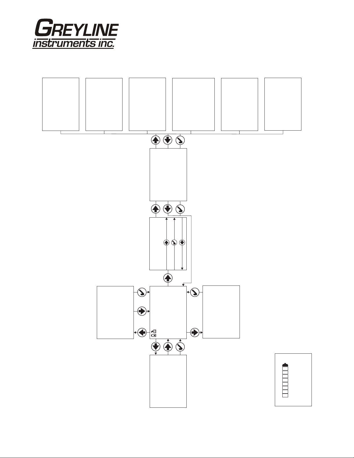
KEYPAD SYSTEM
The following diagram shows the PDFM 5.1 menu system. Arrows show the four directions to leave a
menu box. Pressing a corresponding keypad arrow will move to the next item in the direction shown.
Move the cursor (highlighted) under numerals and increase or decrease numerals with the and
keys.
To store calibration values permanently, press the .
SLEEP
BACK
LIGHT
Page 5
ON
OFF
Page 6
CALIBRATION MENU
PDFM 5.1 Portable Doppler Flow Meter
16Doppler 1.
15Logger 1. S
Flow4-20mA 4.00
Linear in
Volume USG
Time min
Mode Flow}
--Units/Mode--------
--Calibration-------
4mA at 0.000USG/m
Min Vel 0.000ft/s
Pipe ID 12.00in
20mA at 2500.0 USG/m} 0
Damping 20%
Mode Flow
Set Date 20Nov 25/ 14
Set Time 11:27:40
Log Site ID 0}
--Data Logging-------
Log Logging
Interval 10sec
Units / Mode}
--Menu Selections----
--Password----------
--Special Functions-
Calibration
Data Logging
Special Functions
Simulation
Password 0000
Backlight High
Reset Totalizer NO
Negative Totals NO
Flo Direction Off
Cal Constant 1.000
Language English}
Configuration
Restore Defaults NO
New Password 0000
Flow 0.00USG/m
--Simulation--------
} Test Actual
Relays 0
Utility 1. .0} 29 2
--Configuration-----
Analog Out 1
USG/m
0. 000
Data log Logging
Log Used 0%
Battery 50%
Charger Off
--Message-----------
Sensor Good
Tot 20130.8USG
Total 135470.0USG
Average 1125.3USG/m
Maximum 2725.0USG/m
Max Time 08:57:00
Minimum 0.000USG/m
Date Mar. 24/2010}
--24 hr log----------
Min Time 07:35:00
Page 6
020mA at 2500.0 USG/m
Tot 0.000USG
Signal Cutoff 10%
Signal Strength 0%
Velocity 0.00ft/s}
--Status------------
Charging
Page 7
PDFM 5.1 Portable Doppler Flow Meter
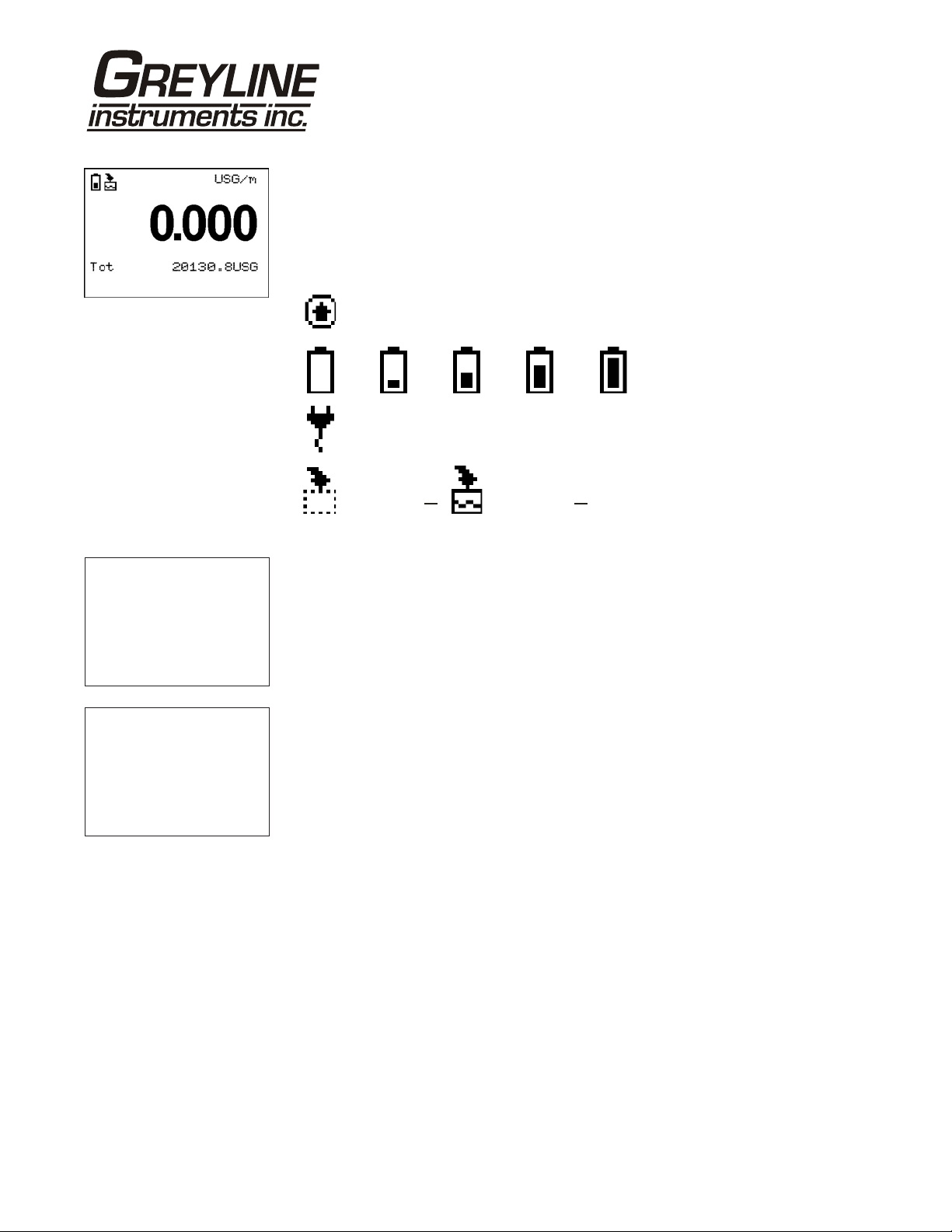
MAIN DISP LAY
The main display shows the units selected from the Units/Mode menu, Flow or
Velocity rate being measured, TOTALIZER. The PDFM 5.1 will start-up with
this display.
Messag e i s w ai t in g . (An i mated)
--Message----------Data log Logging
Log Used 0%
Battery 50%
Charger Off
Sensor Good
--Status------------
Velocity 0.00ft/s
}
Tot 0.000USG
Signal Cutoff 10%
Signal Strength 0%
20mA at 2500.00USG/m
Battery
0%
Unit plugged into charger.
Data logging is .off
Battery
25%
Battery
50%
Data logging is . (Animated)on
Battery
75%
Battery
(Animated when charging)
100%
MESSAGE ICON
Press from the MAIN display to view error/warning messages provided by the
instrument. The Message icon will appear on the MAIN display if error messages
are being generated by the instrument. Press to return to the main display.
STATUS
Press from the MAIN display to view instrument status. Velocity will be
displayed in ft/sec or m/sec.
Tot Displays the current totalizer reading.
Signal Cutoff Adjust the setting in percent to suppress flow readings at
zero flow when fluid swirling or pipe vibration may
cause the instrument to continue reading. Example:
Signal Cutoff at 5% will force the display and outputs to
zero when signal strength drops below 5%.
Signal Strength Displays percentage of signal being received by the
ultrasonic sensor.
20mA at Displays the flow rate set as 20mA in the Calibration
menu. Press to return to the main display.
Page 7
Page 8
PDFM 5.1 Portable Doppler Flow Meter
--24 hr log---------Date Mar. 24/2010
}
Total 135470.0USG
Average 1125.3USG/m
Maximum 2725.0USG/m
Max Time 08:57:00
Minimum 0.000USG/m
Min Time 07:35:00
--Password----------
Password 0000
24 HR LOG
Press from the MAIN display to view a formatted flow report from instruments
with a built-in data logger. Press to scroll down one day or repeatedly to scroll
to a specific date. Up to 365 days can be stored. Newest date will overwrite the
oldest. Press to return to the main display.
PASSWORD
The password (a number from 0000 to 9999) prevents unauthorized access to the
Calibration menu.
From the Main display press the key to get to
password is 0000 and if it has not been changed press the to proceed to the
Password. Factory default
Menu Selections screen.
If a password is required, press to place the highlight under the first digit and
or to set the number, then to the second digit, etc. Press or to proceed
to the
Menu Selections screen.
A new password can be stored by going to
Password
.
Special Functions/New
Page 8
Page 9
PDFM 5.1 Portable Doppler Flow Meter
--Units/Mode-------Mode Flow
}
Linear in
Volume USG
Time min
--Units/Mode--------
Mode Flow
Linear} in
--Units/Mode--------
}Volume USG
ft3
bbl
IMG
USMG
--Units/Mode--------
Mode Flow
Linear in
Volume USG
Time} sec
day
min
ft
mm
m3
IG
hr
UNITS/MODE
From
Velocity. Flow mode displays the flow rate in engineering units (e.g. gpm,
Mode press the and then the or to select Flow or
litres/sec, etc.) Press the to store your selection then the to the next menu
item and to enter.
From
Linear press the key and then the or to select your units of
measurement. Press the to store your selection.
m
Press the key to move the symbol to each subsequent menu item and the to
save your selections.
Note: the volume selection "bbl" denotes U.S. oil barrel.
Press or to return to the
L
Menu Selections screen.
Page 9
Page 10

PDFM 5.1 Portable Doppler Flow Meter
--Calibration------20mA at 2500.00USG/m
}
4mA at 0.000USG/m
Min Vel 0.000ft/s
Pipe ID 12.00in
Damping 20%
CALIBRATION
Press the to
Calibration and to enter. Use or to position
before each menu item and to enter. When settings are completed press to
store and return to the
Calibration menu.
*20mA at Press then or to change the numbers and decimal point.
Use this menu to set the corresponding flow rate that will be
represented by 20mA analog output. If maximum flow is
unknown, enter an estimated flow rate and observe actual flow to
determine the correct maximum value. Any velocity or flow rate
up to +40 ft/sec (12.2 m/sec) may be selected.
*4mA at Press or to set the flow rate corresponding to 4mA analog
output. This setting may be left at zero flow (or velocity or can
be raised to any value less than the 20mA setting, or lowered to
any velocity or corresponding flow rate down to -40 ft/sec (-12.2
m/sec).
Min Vel Press and enter a minimum velocity cutoff. Forward and
reverse velocities less than
Min Vel will be forced to zero.
Pipe ID Place the highlight under the digits and then or to change
the numbers and decimal point.
Pipe ID should be entered
as the exact inside diameter of the pipe where the sensor is
mounted. Refer to the Pipe Charts Appendix in this manual for
inside diameter of common pipe types and sizes.
Damping Increase damping to stabilize readings under turbulent flow
conditions. Decrease for fast response to small changes in flow.
Damping is shown in percentage (maximum is 99%). Factory
default is 20%.
Press to return to
Menu Selections.
*Note
4-20mA circuitry is only powered by the AC power module.
To conserve power this output is not active in battery power mode.
Page 10
Page 11

PDFM 5.1 Portable Doppler Flow Meter
--Data Logging------Log Site ID 0}
Mode Flow
Set Date 20Nov 25/ 14
Set Time 11:27:40
Interval 10sec
Log Logging
DATA LOGGING
Setup
Select
Data Logging from Menu Selections.
Log Site ID Enter a number from 00 to 99. The site ID will become part of
the downloaded file name to help distinguish downloads from
different instruments. Press to store the setting.
Set Date Press or to scroll and select Month, Day and Year.
Press to store the setting.
Set Time Press or to select the current time in Hours, Minutes and
Seconds. Press to store the setting.
Interval Press or to select the logging interval.
Press to store the setting.
Log Select Start then to start logger. Select Stop then to
stop logger. Select
Delete then to clear all previous
logging sessions.
RETRIEVE LOG FILE
Install Greyline Logger on your PC or laptop. Refer to the Help menu in the
program for detailed instructions.
- Connect the PDFM 5.1 to the PC using the supplied USB cable.
- Install the USB driver program from the install CD.
- Start the Greyline Logger Software.
- Select "xxxx scan for USB instruments xxxx" in the drop down window at the
top of the main window. PDFM 5.1 will be indicated.
- Click the download icon to start transferring data.
- Downloaded data appears in a pop-up window.
Page 11
Page 12

PDFM 5.1 Portable Doppler Flow Meter
--Special FunctionsLanguage English}
Backlight High
Reset Totalizer NO
Negative Totals NO
Flo Direction Off
Cal Constant 1.000
Restore Defaults NO
New Password 0000
SPECIAL FUNCTIONS
Language Select English, French or Spanish
Backlight
Select High, Medium or Low for continuous
backlight.
Select
minute) after a keypress and then
Key Hi/Lo for high backlight (for 1
Lo backlight until
a key is pressed again.
Select
Key High, Med or Low for backlight
after a keypress and then backlight off until a key is
pressed again.
Reset Totalizer Press and select Yes to erase and restart the
totalizer at zero.
Negative Totals Select Yes to have reverse flow readings deducted
from the totalizer. Select
NO to totalize forward
flow only and ignore reverse flow.
Flo Direction Select On to enable flow direction measurement.
Select
Select
Off to disable flow direction measurement.
Invert to invert the sense of the flow
measurement.
Cal Constant Scales the velocity reading. Factory value is close to
1.000 for a PSE4-A sensor.
Restore Defaults Select Yes and press to erase all user settings
and return the instrument to factory default settings.
New Password Select any number from 0000 to 9999 and press .
Default setting of 0000 will allow direct access to the
calibration menus. Setting of any password greater
than 0000 will require the password to be entered to
access the calibration menus.
Press to return to
Menu Selections.
Page 12
Page 13

PDFM 5.1 Portable Doppler Flow Meter
--Simulation-------Test Actual
}
Flow 0.00USG/m
4-20mA Flow 4.00
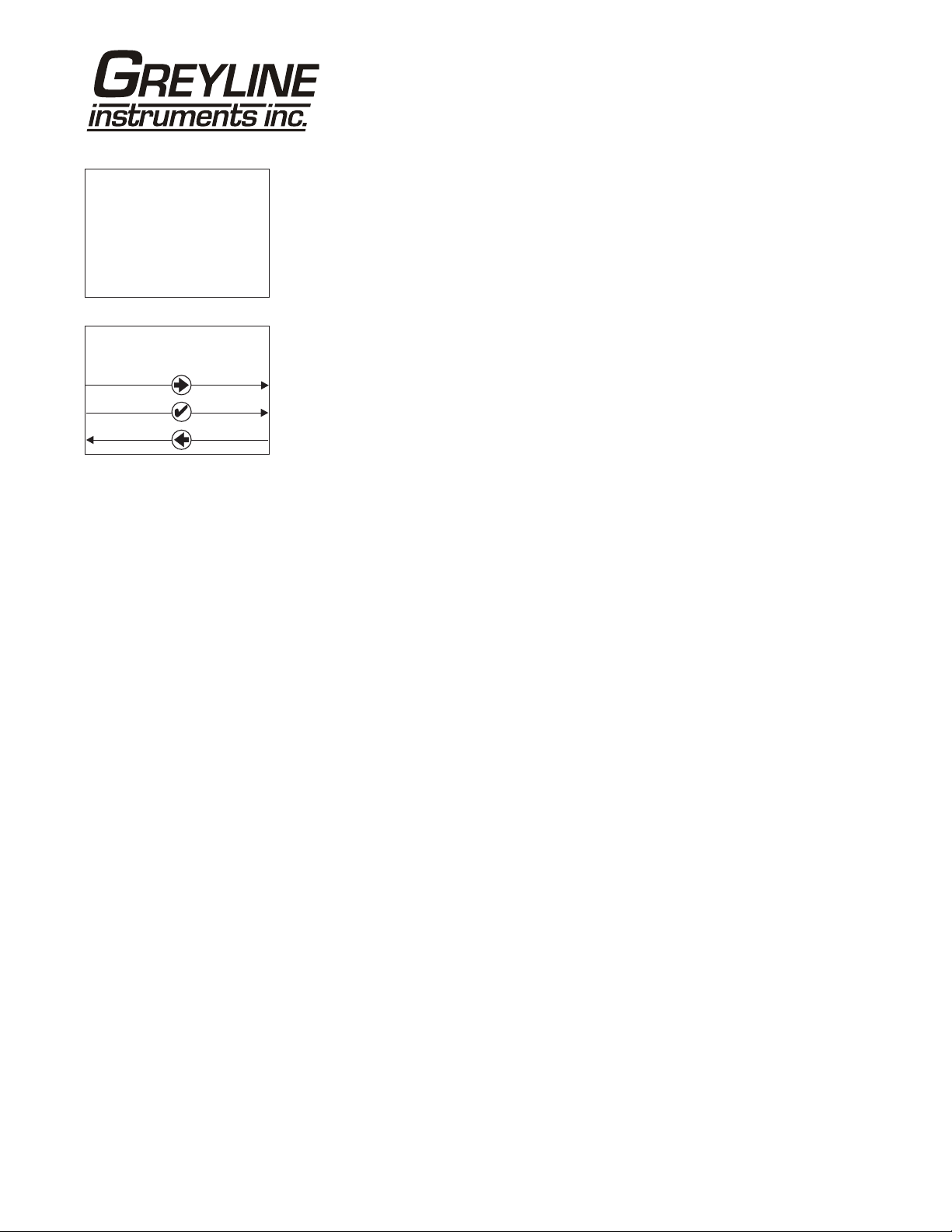
SIMULATION
Exercises the 4-20mA.
Test Select Maximum and press to simulate maximum Flow or Velocity
and to output 20mA to the analog channel.
Select
Minimum and press to simulate minimum Flow or Velocity
and to output 4mA to the analog channel.
To simulate measurements between minimum and maximum set
to
Actual and then enter for the flow measurement. The analog output
will respond to the simulated value.
SLEEP MODE
Logging in sleep mode requires a minimum sample time of 30 seconds. Selecting
sleep mode for 10 second sampling rate results in instrument always being
‘awake’.
CHARGING
A flashing battery indicates charging.
A solid battery indicates fully charged.
Test
Page 13
Page 14

PDFM 5.1 Portable Doppler Flow Meter
SENSOR MOUNTING LOCATION
The position of the sensor is one of the most important considerations for accurate Doppler flow
measurement. The same location guidelines apply to Doppler as most other types of flow meters.
Before permanently mounting a Doppler sensor onsite testing is recommended to determine optimum
mounting position. Use the sensor coupling compound (supplied with each Greyline flow meter, or
petroleum gel, acoustic compound or electrocardiograph gel). Take several readings around the axis of
the pipe and then at several points upstream and downstream from the selected position, checking for
consistent readings. Avoid high or low reading areas. Mount the sensor where consistent (average)
readings were obtained or continue testing on another pipe section.
VERTICAL OR HORIZONTAL PIPE - Vertical pipe
12 O'CLOCK POSITION WITH
LOW GAS CONTENT
runs generally provide evenly distributed flow. On
Horizontal pipes and liquids with high concentrations
of gas or solids, the sensor should be mounted on the
side (3 or 9 o’clock position) to avoid concentrations of
3 O'CLOCK POSITION WITH HIGH
GAS OR SOLIDS CONTENT
gas at the top of the pipe, or solids at the bottom. For
liquids with minimal gas bubbles (e.g. potable water)
the sensor should be mounted on the top of a horizontal
HAS EVENLY DISTRIBUTED FLOW
VERTICAL PIPE USUALLY
pipe (12 o’clock position) to obtain the best signal strength.
VELOCITY INCREASING DEVICES: Generally the sensor must be mounted away from flow
disturbances such as valves, pumps, orifice plates, venturis or pipe inlets and discharges which tend to
increase flow velocity. Velocity increasing devices often cause cavitation, or rapid release of gas
bubbles, and readings both up and downstream may show much higher velocity. As a guideline, mount
the sensor at least 20 diameters upstream or 30 diameters downstream from velocity increasing devices.
Required distance from a velocity increasing device will vary in applications depending on the flow
velocity and the characteristics of the liquid itself.
TURBULENCE INCREASING DEVICES: Elbows,
SENSOR MOUNTS 6 DIAMETERS
UPSTREAM OR 10 DOWNSTREAM
FROM AN ELBOW
flanged connections and tees tend to introduce
desirable conditions of an evenly distributed flow
profile with some air or gases entrained in the flow.
Sensor mounting 6 pipe diameters upstream and 10
FLOW
diameters downstream from these disturbances is
generally optimum.
The sensor is designed to mount longitudinally on a straight section of pipe. Do not attempt to mount it
on bends, elbows or fittings.
Page 14
Page 15

PDFM 5.1 Portable Doppler Flow Meter
SENSOR MOUNTING
Prepare an area 2" wide by 4" long (50mm x 100mm) for sensor bonding by removing loose paint, scale
and rust. The objective of site preparation is to eliminate any discontinuity between the sensor and the
pipe wall, which would prevent acoustical coupling.
A PC4 Sensor Mounting Kit is supplied with each Greyline flow meter. It includes recommended
coupling compound in a plastic applicator and a stainless steel mounting bracket with adjustable pipe
straps.
SENSOR
PIPE
END VIEW
PIPE
Mountthe PC4 pipe clamp as illustrated on pipes
0.6"/15mmODor larger.Stainless steel bands are
included for mounting on pipes up to 32" / 81 cm OD.
Additionalstainless steel bands (by customer)maybe
combined to mounton pipes up to 180" / 4.5 m OD.
SENSOR
ADJUSTABLE
STAINLESS
STEEL STRAP
PIPE
PIPE
Page 15
Page 16

PDFM 5.1 Portable Doppler Flow Meter
SENSOR COUPLING
For permanent or temporary bonding, the following are recommended:
a) Dow Corning silicon compound #4 (supplied)
Additional supply: order Greyline Option CC
b) High Temperature compound
Additional supply: order Greyline Option AP-1W
c) Water-based sonic compound: Order Greyline Option CC30
d) Electrocardiograph gel
e) Petroleum gel (Vaseline)
The above are arranged in their order of preferred application.
d & e are only good for temporary bonding at room temperature.
DO NOT USE: Silicon RTV caulking compound (silicon rubber).
Use the PC4 pipe clamp (supplied) as illustrated above or
use a loop of electrical tape for temporary mounting. Apply
COMPOUND
silicon coupling compound #4 to the coloured face of the
sensor. A bead, similar to toothpaste on a toothbrush, is
ideal. Do not overtighten (crush the sensor).
SENSOR
The sensor must be fixed securely to the pipe with coupling material
COMPOUND
between the sensor face and the pipe. Sensor installation with
excessive coupling compound can result in gaps or voids in the
SENSOR
PIPE
coupling and cause errors or loss of signal. Insufficient coupling
compound will create similar conditions.
TAPE OR
CLAMP
Over time temporary coupling compounds (e.g. Petroleum Gel) may
gradually sag away from the sensor resulting in reduced signal strength and finally complete loss of
signal. Warm temperatures, moisture and vibration will accelerate this process. Dow Corning Silicone
Compound #4 as supplied with the PDFM 5.1 (and available from Greyline Instruments) is
recommended for semi-permanent installations.
Page 16
Page 17

PDFM 5.1 Portable Doppler Flow Meter
SENSOR MOUNTING/COUPLING RECOMMENDATIONS
BAD
GOOD
Page 17
Page 18

PDFM 5.1 Portable Doppler Flow Meter
FIELD TROUBLESHOOTING
Possible Causes: Corrective Action:
METER READING LOWER THAN EXPECTED
Calibration Error
Lower flow rate than expected
Signal not penetrating far enough into the flow stream
Improper mounting of sensor
Pipe is not full
METER READING WHEN THERE IS NO FLOW
Vibration on pipe
Variable Speed Drive interference
Review UNITS/MODE menu and Pipe ID
Investigate pump/valves. Compare velocity
with alternate instrument
Relocate sensor closer to elbows or flow
disturbances
Reinstall Sensor with careful application of
Coupling Compound
Remount Sensor on vertical pipe
Adjust Status / Signal Cutoff setting
Install in another location
Follow Drive manufacturers wiring and
Grounding instructions
Relocate Flowmeter, Sensor and wiring away
from VSD
Sensor connections incorrect
METER READING ERRATIC
Sensor mounted too close to valve, pump or elbow
NO FLOW INDICATION
Not enough suspended particles or gases in the fluid
Refer to Connections diagram
Change sensor placement. Recommended 6-10
diameters from elbows, and 30 diameters from
pumps, controlling valves, orifice plates,
nozzles or open pipe discharge
Relocate sensor in more turbulent pipe section.
Mount sensor at 12 o'clock position on
horizontal pipe
Page 18
Page 19

PDFM 5.1 Portable Doppler Flow Meter
Possible Causes: Corrective Action:
Coupling compound washed out, or sensor loose on
pipe
METER READING TOO HIGH
Calibration error
Vibration or noise on the pipeline
Pipe is not full
Nearby velocity increasing device (pump, valve, orifice
plate)
Variable Speed Drive interference
Use Dow Corning Silicone #4
Relocate Flowmeter, Sensor and wiring away
Remount sensor
Review UNITS/MODE menu and Pipe ID
Install in another location.
Remount Sensor on vertical pipe
Relocate sensor >30 pipe diameters from
velocity increasing device
Follow Drive manufacturers wiring and
Grounding instructions
from VSD
Page 19
Page 20

PDFM 5.1 Portable Doppler Flow Meter
COMMON QUESTIONS AND ANSWERS
The pipe vibrates. Will it affect the flow meter?
Common vibration frequencies are far lower than the sonic frequencies used by the Greyline flow meter,
and will not normally affect accuracy or performance. However, applications where very weak Doppler
signal is present (when sensitivity is adjusted to maximum and signal strength is low), accuracy may be
affected by pipe vibration, or the flow meter may show readings under no-flow conditions. Attempt to
relocate the sensor on a pipe section where vibration is reduced, or arrange pipe mounting brackets to
reduce vibration at the sensor mounting location.
The flow meter must be installed in a high noise environment. Will this affect operation?
Greyline flow meters are designed to discriminate between environmental noise and the Doppler signal.
High noise environments may affect the flow meter’s performance where low signal strength and/or low
flow velocities are being measured. Relocate the sensor in a more quiet environment if possible.
Will pipe corrosion affect accuracy of the flow meter?
Yes. Rust, loose paint etc. must be removed from the outside of the pipe to provide a clean mounting
position when installing a Doppler sensor. Severe corrosion/oxidation on the inside of the pipe may
prevent the Doppler signal from penetrating into the flow. If the pipe cannot be cleaned, a spool piece
(PVC recommended) should be installed for sensor mounting.
What effect do pipe liners have on the flow meter?
The air gap between loose insertion liners and the pipe wall prevent the Doppler signal from entering the
flow. Better results can be expected with bonded liners such as cement, epoxy or tar, however an on site
test is recommended to determine if the application is suitable for a Doppler flow meter.
Why is Doppler only recommended for liquids containing suspended solids or gases?
The Doppler sensor transmits sound into the flow stream which must be reflected back to the sensor to
indicate flow velocity. Gas bubbles or suspended solids act as reflectors for the Doppler signal. As a
guideline, Greyline Doppler flow meters are recommended for liquids containing solids or bubbles with
a minimum size of 100 microns and a minimum concentration of 75 ppm. Most applications (except
potable, distilled or deionized water) will meet this minimum requirement.
Can the sensor be submerged in water?
Yes, for short periods of time or by accident, but it is not recommended for continuous operation. The
sensor is constructed to withstand submersion to 10 psi without damage, but external liquid moving in
contact with the sensor can be interpreted as flow and cause false readings.
What is the purpose of the Signal Strength Display?
Doppler signals of very low strength are not accepted or processed by the instrument. This feature
assists in rejection of environmental noise and vibration. Use the display to evaluate signal strength in
your application. Strong signals will increase in percentage to a maximum of 100% or greater.
Page 20
Page 21

PDFM 5.1 Portable Doppler Flow Meter
Does the PDFM 5.1 require periodic recalibration?
PDFM 5.1 calibration does not drift over time. The solid state sensor has no moving parts to wear and
affect calibration. The Doppler flow technique generates an ultrasonic signal proportional to the velocity
of flow. All Greyline timing/counting circuits use crystal-controlled frequency references to eliminate
any drift in the processing circuitry.
ISO 9000 or similar quality management systems may require periodic and verifiable recalibration of
flow meters. PDFM 5.1 Doppler Flow Meters may be returned to Greyline for factory calibration and
issue of a new NIST traceable certificate. Refer to the ‘Product Return Procedure’ section of this manual
for return instructions.
Page 21
Page 22

PDFM 5.1 Portable Doppler Flow Meter
APPLICATIONS HOTLINE
For applications assistance, advice or information on any Greyline Instrument contact your Sales
Representative, write to Greyline or phone the Applications Hotline below:
United States: Tel: 315-788-9500 Fax: 315-764-0419
Canada: Tel: 613-938-8956 Fax: 613-938-4857
Toll Free: 888-473-9546
Email: info@greyline.com
Web Site: www.greyline.com
Greyline Instruments Inc.
Canada USA:
16456 Sixsmith Drive 105 Water Street
Long Sault, Ont. K0C 1P0 Massena, NY 13662
Page 22
Page 23

PDFM 5.1 Portable Doppler Flow Meter
PRODUCT RETURN PROCEDURE
Instruments may be returned to Greyline for service or warranty repair.
1 Obtain an RMA Number from Greyline -
Before shipping a product to the factory please contact Greyline by telephone, fax or email to obtain an
RMA number (Returned Merchandise Authorization). This ensures fast service and correct billing or
credit.
When you contact Greyline please have the following information available:
1. Model number / Software Version
2. Serial number
3. Date of Purchase
4. Reason for return (description of fault or modification required)
5. Your name, company name, address and phone number
2 Clean the Sensor/Product -
Important: unclean products will not be serviced and will be returned to the sender at their expense.
1. Rinse sensor and cable to remove debris.
2. If the sensor has been exposed to sewage, immerse both sensor and cable in a solution of 1 part
household bleach (Javex, Clorox etc.) to 20 parts water for 5 minutes. Important: do not immerse plug
end of sensor cable.
3. Dry with paper towels and pack sensor and cable in a sealed plastic bag.
4. Wipe the outside of the enclosure to remove dirt or deposits.
5. Return to Greyline for service.
3 Ship to Greyline -
After obtaining an RMA number please ship the product to the appropriate address below:
Canadian and International USA
Customers: Customers:
Greyline Instruments Inc. Greyline Instruments Inc.
16456 Sixsmith Drive 204 150th Avenue
Long Sault, Ont. K0C 1P0 Madeira Beach, FL 33708
RMA# RMA#
Page 23
Page 24

PDFM 5.1 Portable Doppler Flow Meter
FLOW METER DATA SHEET
Greyline Instruments Inc.
16456 Sixsmith Dr., Long Sault, Ont. K0C 1P0
Tel: 613-938-8956 / Fax: 613-938-4857
105 Water Street, Massena NY 13662
Tel: 315-788-9500 / Fax: 315-764-0419
Contact: ________________________________ Title/Dept.: _________________________
Company: ___________________________________ Project: _________________________
Address: ____________________________________________________________________
Tel: _____________________________________ Fax: _________________________
SENSOR
Model/Type: _____________________________ Cable Length: _________________________
Elec. Class: _____________________________ Type of Pump: _________________________
Distance from nearest Pump, Controlling Valve, Orifice or open Discharge: ___________________
INSTRUMENT
Calibrated Range: ___________________________ Indication: _________________________
Operating Temp.: ___________________________ Alarm: _________________________
Enclosure Class
:
:
Model/Type: _________________________ Power Input: _________________________
: __________________________ Pulse/Unit: _________________________
Elec. Class: _____________________________ Output: _________________________
Please complete and return this form to Greyline. It is
important. We use this information to check our database
for performance of Greyline flow meters in similar
applications, and to provide advice and recommendations
to you. Thanks for your cooperation.
SERVICE CONDITIONS
Pipe ID: _______________________________
Pipe Mat'l: _______________________________ % Solids: _________________________
Fluid: __________________________ Material Build-up: _________________________
Oper. Flow: _________________________________ Vibration: _________________________
Max. Flow: ____________________________ Max. Pressure: _________________________
Min. Flow: _____________________________ Max. Temp: _________________________
Notes / Sketch Pipe Run:
By: _______________________________________________ Date: ___________________
:
q
Vertical
q
Horizontal
Page 24
Page 25

y
LIMITED WARRANTY
_____________________________________
Greyline Instruments warrants, to the original purchaser, its
products to be free from defects in material and workmanship for a
period of one year from date of invoice. Greyline will replace or
repair, free of charge, any Greyline product if it has been proven to
be defective within the warranty period. This warranty does not
cover any expenses incurred in the removal and re-installation of
the product.
PDFM 5.1 Portable Doppler Flow Meter
If a product manufactured by Greyline should prove defective
within the first year, return it freight prepaid to Greyline
Instruments along with a copy of your invoice.
This warranty does not cover damages due to improper installation
or handling, acts of nature, or unauthorized service. Modifications
to or tampering with any part shall void this warranty. This
warranty does not cover any equipment used in connection with the
product or consequential damages due to a defect in the product.
All implied warranties are limited to the duration of this warranty.
This is the complete warranty by Greyline and no other warranty is
valid against Greyline. Some states do not allow limitations on how
long an implied warranty lasts or limitation of incidental or
consequential damages, so the above limitations or exclusions may
not apply to you.
This warranty gives you specific legal rights, and you may also
have other rights which vary from state to state.
line Instruments Inc.
Gre
Page 25
Page 26

PDFM 5.1 Portable Doppler Flow Meter
SPECIFICATIONS
4.33”
110 mm
1.6”
41 mm
Flow Rate Range: ± 0.1 to 40 ft/sec (± 0.03 to 12.2
m/sec) in most applications
Pipe Size: Ultrasonic Sensor mounts on any
pipe from 1/2" to 180" ID (12.5 mm
to 4.5m)
Display: White, backlit matrix - displays
flow rate, totalizer, operating mode
and calibration menu
Power Input: Built-in NiMH battery for up to 18
hours continuous operation
8”
204 mm
External charger with 100-
240VAC 50/60Hz input
Outputs: 4-20mA (500 ohm) when AC
powered
USB for Data Log transfer by
direct PC connection
Data Logger: Programmable 300,000 data point
capacity, time and date stamped
ENCLOSURE
or formatted flow reports including total, average, minimum, maximum
and times of occurrence
PC Software: 'Greyline Logger' for Windows 98 or higher. Retrieves, displays and
saves data log files
Electronics Operating
Temperature: -10° to 140°F (-23° to 60°C)
Electronics Enclosure: Portable, ABS enclosure
Carry Case: Rated IP67 with protective molded foam insert
Accuracy: ±2% of full scale, requires solids or bubbles minimu m size of 100
microns, minimum concentration 75 ppm. Repeatability: ±0.25%,
Linearity: ±0.5%
Calibration: Built-in 5-key programming with user-friendly calibration menu.
Password protected.
Language Selection: English, French, Spanish
Sensitivity: Adjustable signal cut-off, signal strength and damping
Approvals: Charger is CE and UL approved. The PDFM 5.1 is not certified for use
in hazardous rated locations.
Page 26
Page 27

PDFM 5.1 Portable Doppler Flow Meter
PSE4 Doppler Sensor
Minimum Pipe Diameter: 0.5" (12.5 mm) ID, 0.6" (15 mm) OD
Maximum Pipe Diameter: 180" (4.5 m) ID
Operating Temperature: -40° to 300°F (-40° to 150°C)
Operating Frequency: 640 KHz
Sensor Housing: Stainless Steel
Sensor Cable: 12 ft. (3.66 m) shielded coaxial pair
Submersion Rating: Withstands accidental submersion pressure up to 10 psi (0.7 Bar)
END
VIEW
1.375”
35 mm
1.5”
38 mm
SIDE VIEW
3.375” / 85 mm
12 ft / 3.6 m
Options
Sensor Cable: 50 ft (15 m) sensor cable extension, shielded, with connectors
Sensor Mounting: Extra silicone coupling compound. Additional stainless steel pipe
clamps
Carrying Case: Watertight carrying case with foam inserts
Page 27
Page 28

APPENDIX A - CONVERSION TABLE
CONVERSION GUIDE
FROM TO MULTIPLY BY
US GALLONS CUBIC FEET 0.1337
US GALLONS IMPERIAL GALS 0.8327
US GALLONS LITRES 3.785
US GALLONS CUBIC METERS 0.003785
LITRES/SEC GPM 15.85
PDFM 5.1 Portable Doppler Flow Meter
LITRES CUBIC METERS 0.001
BARRELS US GALLONS 42
BARRELS IMPERIAL GALS 34.9726
BARRELS LITRES 158.9886
INCHES MM 25.4
DEGREES F DEGREES C (°F-32) x 0.556
POUNDS KILOGRAMS 0.453
PSI BAR 0.0676
FOOT² METER² 0.0929
Note: BARRELS are U.S. oil barrels.
Page 28
Page 29

PDFM 5.1 Portable Doppler Flow Meter
PIPE CHARTS
Carbon Steel & PVC Pipe
Pipe Pipe Standard Extra Heavy Dbl. Extra Heavy Schedule 10 Schedule 20 Schedule 30 Schedule 40
Size O.D. I.D. WALL I.D. WALL I.D. WALL I.D. WALL I.D. WALL I.D. WALL I.D. WALL
½ .840 .622 .109 .546 .147 .252 .294 .622 .109
¾ 1.050 .824 .113 .742 .154 .434 .308 .824 .113
1 1.315 1.049 .133 .957 .179 .599 .358 1.049 .133
1¼ 1.660 1.380 .140 1.278 .191 .896 .382 1.380 .140
1½ 1.900 1.610 .145 1.500 .200 1.100 .400 1.610 .145
2 2.375 2.067 .154 1.939 .218 1.503 .436 2.067 .154
2½ 2.875 2.469 .203 2.323 .276 1.771 .552 2.469 .203
3 3.500 3.068 .216 2.900 .300 2.300 .600 3.068 .216
3½ 4.000 3.548 .226 3.364 .318 2.728 .636 3.548 .226
4 4.500 4.026 .237 3.826 .337 3.152 .674 4.026 .237
5 5.563 5.047 .258 4.813 .375 4.063 .750 5.047 .258
6 6.625 6.065 .280 5.761 .432 4.897 .864 6.065 .280
8 8.625 7.981 .322 7.625 .500 6.875 .875 8.125 .250 8.071 .277 7.981 .322
10 10.750 10.020 .365 9.750 .500 8.750 1.000 10.250 .250 10.136 .307 10.020 .365
12 12.750 12.000 .375 11.750 .500 10.750 1.000 12.250 .250 12.090 .330 11.938 .406
14 14.000 13.250 .375 13.000 .500 13.500 .250 13.376 .312 13.250 .375 13.124 .438
16 16.000 15.250 .375 15.000 .500 15.500 .250 15.376 .312 15.250 .375 15.000 .500
18 18.000 17.250 .375 17.000 .500 17.500 .250 17.376 .312 17.124 .438 16.876 .562
20 20.000 19.250 .375 19.000 .500 19.500 .250 19.250 .375 19.000 .500 18.814 .593
22 22.000 21.250 .375 21.000 .500 21.500 .250 21.250 .375 21.000 .500
24 24.000 23.250 .375 23.000 .500 23.500 .250 23.250 .375 22.876 .562 22.626 .687
26 26.000 25.250 .375 25.000 .500 25.376 .312 25.000 .500
28 28.000 27.250 .375 27.000 .500 27.376 .312 27.000 .500 26.750 .625
30 30.000 29.250 .375 29.000 .500 29.376 .312 29.000 .500 28.750 .625
32 32.000 31.250 .375 31.000 .500 31.376 .312 31.000 .500 30.750 .625
34 34.000 33.250 .375 33.000 .500 33.376 .312 33.000 .500 32.750 .625
36 36.000 35.250 .375 35.000 .500 35.376 .312 35.000 .500 34.750 .625
42 42.000 41.250 .375 41.000 .500 41.000 .500 40.750 .625
Ductile IronPipe - Standard C lasses
Size OUTSI DE Class Class Cl ass C lass Cl ass C lass Cla ss CEMEN T L ININ G
INCH DIA. 50 51 52 53 54 55 56 **STD **DOUBLE
INCH WALL I.D. WALL I.D. WALL I.D. WALL I.D. WA LL I.D. WALL I .D. WALL I.D. THIC KNES S TH ICKN ESS
3 3.96 0 .2 5 3 .4 6 0 .2 8 3 .4 0 0 .3 1 3 .3 4 0 .3 4 3 .2 8 0 .3 7 3 .2 2 0 .4 1 3 .1 4
4 4.80 0 .2 6 4 .2 8 0 .2 9 4 .2 2 0 .3 2 4 .1 6 0 .3 5 4 .1 0 0 .3 8 4 .0 4 0 .4 4 3 .9 3
6 6.90 0 .2 5 6 .40 0 .2 8 6 .3 4 0 .3 1 6 .2 8 0 .3 4 6 .2 2 0 .3 7 6 .1 6 0 .4 0 6 .1 0 0 .4 3 6 .0 4 .12 5 .25 0
8 9.05 0 .2 7 8 .51 0 .3 0 8 .4 5 0 .3 3 8 .3 9 0 .3 6 8 .3 3 0 .3 9 8 .2 7 0 .4 2 8 .2 1 0 .4 5 8 .1 5
10 11 .10 0.39 10 .32 0 .32 10. 46 0. 35 10.40 0 .38 10.34 0. 41 10.28 0. 44 10.22 0. 47 10.16
12 13 .20 0.31 12 .58 0 .34 12. 52 0. 37 12.46 0 .40 12.40 0. 43 12.34 0. 46 12.28 0. 49 12.22
14 15 .30 0.33 14 .64 0 .36 14. 58 0. 39 14.52 0 .42 14.46 0. 45 14.40 0. 48 14.34 0. 51 14.28
16 17 .40 0.34 16 .72 0 .37 16. 66 0. 40 16.60 0 .43 16.54 0. 46 16.48 0. 49 16.42 0. 52 16.36
18 19 .50 0.35 18 .80 0 .38 18. 74 0. 41 18.68 0 .44 18.62 0. 47 18.56 0. 50 18.50 0. 53 18.44 .1875 .375
20 21 .60 0.36 20 .88 0 .39 20. 82 0. 42 20.76 0 .45 20.70 0. 48 20.64 0. 51 20.58 0. 54 20.52
24 25 .80 0.38 25 .04 0 .41 24. 98 0. 44 24.92 0 .47 24.86 0. 50 24.80 0. 53 24.74 0. 56 24.68
30 32 .00 0.39 31 .22 0 .43 31. 14 0. 47 31.06 0 .51 30.98 0. 55 30.90 0. 59 30.82 0. 63 30.74
36 38 .30 0.43 37 .44 0 .48 37. 34 0. 62 37.06 0 .58 37.14 0. 63 37.04 0. 68 36.94 0. 73 36.84
42 44 .50 0.47 43 .56 0 .53 43. 44 0. 59 43.32 0 .65 43.20 0. 71 43.08 0. 77 42.96 0. 83 42.84 .250 .50 0
48 50 .80 0.51 49 .78 0 .58 49. 64 0. 65 49.50 0 .72 49.36 0. 79 49.22 0. 86 49.08 0. 93 48.94
54 57 .10 0.57 55 .96 0 .65 55. 80 0. 73 55.64 0 .81 55.48 0. 89 55.32 0. 97 55.16 1. 05 55.00
**REDUCE I.D. BY DIMENSION SHOWN
Page 29
Page 30

PDFM 5.1 Portable Doppler Flow Meter
Stainless Steel, Hastelloy "C" & Titanium Pipe
Pipe Pipe Scheule 5 S (a) Schedule 10 S (a) Schedule 40 S Schedule 80 S
Size O.D. I.D. WALL I.D. WALL I.D. WALL I.D. WALL
½ .840 .710 .065 .674 .083 .622 .109 .546 .147
¾ 1.050 .920 .065 .884 .083 .824 .113 .742 .154
1 1.315 1.185 .065 1.097 .109 1.049 .133 .957 .179
1¼ 1.660 1.530 .065 1.442 .109 1.380 .140 1.278 .191
1½ 1.900 1.770 .065 1.682 .109 1.610 .145 1.500 .200
2 2.375 2.245 .065 2.157 .109 2.067 .154 1.939 .218
2½ 2.875 2.709 .083 2.635 .120 2.469 .203 2.323 .276
3 3.500 3.334 .083 3.260 .120 3.068 .216 2.900 .300
3½ 4.000 3.834 .083 3.760 .120 3.548 .226 3.364 .318
4 4.500 4.334 .083 4.260 .120 4.026 .237 3.826 .337
5 5.563 5.345 .109 5.295 .134 5.047 .258 4.813 .375
6 6.625 6.407 .109 6.357 .134 6.065 .280 5.761 .432
8 8.625 8.407 .109 8.329 .148 7.981 .322 7.625 .500
10 10.750 10.482 .134 10.420 .165 10.020 .365 9.750 .500
12 12.750 12.438 .156 12.390 .180 12.000 .375 11.750 .500
14 14.000 13.688 .156 13.624 .188
16 16.000 15.670 .165 15.624 .188
18 18.000 17.670 .165 17.624 .188
20 20.000 19.634 .188 19.564 .218
22 22.000 21.624 .188 21.564 .218
24 24.000 23.563 .218 23.500 .250
Pipe Pipe Schedule 60 Schedule 80 Schedule 100 Schedule 120 Schedule 140 Schedule 160
Size O.D. I.D. WALL I.D. WALL I.D. WALL I.D. WALL I.D. WALL I.D. WALL
½ .840 .546 .147 .466 .187
¾ 1.050 .742 .154 .614 .218
1 1.315 .957 .179 .815 .250
1¼ 1.660 1.278 .191 1.160 .250
1½ 1.900 1.500 .200 1.338 .281
2 2.375 1.939 .218 1.689 .343
2½ 2.875 2.323 .276 2.125 .375
3 3.500 2.900 .300 2.624 .438
3½ 4.000 3.364 .318
4 4.500 3.826 .337 3.624 .438 3.438 .531
5 5.563 4.813 .375 4.563 .500 4.313 .625
6 6.625 5.761 .432 5.501 .562 5.189 .718
8 8.625 7.813 .406 7.625 .500 7.439 .593 7.189 .718 7.001 .812 6.813 .906
10 10.750 9.750 .500 9.564 .593 9.314 .718 9.064 .843 8.750 1.000 8.500 1.125
12 12.750 11.626 .562 11.376 .687 11.064 .843 10.750 1.000 10.500 1.125 10.126 1.312
14 14.000 12.814 .593 12.500 .750 12.126 .937 11.814 1.093 11.500 1.250 11.188 1.406
16 16.000 14.688 .656 14.314 .843 13.938 1.031 13.564 1.218 13.124 1.438 12.814 1.593
18 18.000 16.500 .750 16.126 .937 15.688 1.156 15.250 1.375 14.876 1.562 14.438 1.781
20 20.000 18.376 .812 17.938 1.031 17.438 1.281 17.000 1.500 16.500 1.750 16.064 1.968
22 22.000 20.250 .875 19.750 1.125 19.250 1.375 18.750 1.625 18.250 1.875 17.750 2.125
24 24.000 22.064 .968 21.564 1.218 20.938 1.531 20.376 1.812 19.876 2.062 19.314 2.343
Page 30
Page 31

PDFM 5.1 Portable Doppler Flow Meter
Cast Iron Pipe - ASA Standard
Pipe Pipe Class 50 Class 100 Class 150 Class 200 Class 250 Class 300 Class 350
Size O.D. WALL I.D. WALL I.D. WALL I.D. WALL I.D. WALL I.D. WALL I.D. WALL I.D.
3 3.96 0.32 3.32 0.32 3.32 0.32 3.32 0.32 3.32 0.32 3.32 0.32 3.32 0.32 3.32
4 4.80 0.35 4.10 0.35 4.10 0.35 4.10 0.35 4.10 0.35 4.10 0.35 4.10 0.35 4.10
6 6.90 0.38 6.14 0.38 6.14 0.38 6.14 0.38 6.14 0.38 6.14 0.38 6.14 0.38 6.14
8 9.05 0.41 8.23 0.41 8.23 0.41 8.23 0.41 8.23 0.41 8.23 0.41 8.23 0.41 8.23
10 11.10 0.44 10.22 0.44 10.22 0.44 10.22 0.44 10.22 0.44 10.22 0.48 10.14 0.52 10.06
12 13.20 0.48 12.24 0.48 12.24 0.48 12.24 0.48 12.24 0.52 12.16 0.52 12.16 0.56 12.08
14 15.30 0.48 14.34 0.51 14.28 0.51 14.28 0.55 14.20 0.59 14.12 0.59 14.12 0.64 14.02
16 17.40 0.54 16.32 0.54 16.32 0.54 16.32 0.58 16.24 0.63 16.14 0.68 16.04 0.68 16.04
18 19.50 0.54 18.42 0.58 18.34 0.58 18.34 0.63 18.24 0.68 18.14 0.73 18.04 0.79 17.92
20 21.60 0.57 20.46 0.62 20.36 0.62 20.36 0.67 20.26 0.72 20.16 0.78 20.04 0.84 19.92
24 25.80 0.63 24.54 0.68 24.44 0.73 24.34 0.79 24.22 0.79 24.22 0.85 24.10 0.92 23.96
Cast Iron Pipe - AWWA Standard
Class A Class B Class C Class D
Pipe
Size O.D. WALL I.D. O.D. WALL I.D. O.D. WALL I.D. O.D. WALL I.D.
3 3.80 0.39 3.02 3.96 0.42 3.12 3.96 0.45 3.06 3.96 0.48 3.00
4 4.80 0.42 3.96 5.00 0.45 4.10 5.00 0.48 4.04 5.00 0.52 3.96
6 6.90 0.44 6.02 7.10 0.48 6.14 7.10 0.51 6.08 7.10 0.55 6.00
8 9.05 0.46 8.13 9.05 0.51 8.03 9.30 0.56 8.18 9.30 0.60 8.10
10 11.10 0.50 10.10 11.10 0.57 9.96 11.40 0.62 10.16 11.40 0.68 10.04
12 13.20 0.54 12.12 13.20 0.62 11.96 13.50 0.68 12.14 13.50 0.75 12.00
14 15.30 0.57 14.16 15.30 0.66 13.98 15.65 0.74 14.17 15.65 0.82 14.01
16 17.40 0.60 16.20 17.40 0.70 16.00 17.80 0.80 16.20 17.80 0.89 16.02
18 19.50 0.64 18.22 19.50 0.75 18.00 19.92 0.87 18.18 19.92 0.96 18.00
20 21.60 0.67 20.26 21.60 0.80 20.00 22.06 0.92 20.22 22.06 1.03 20.00
24 25.80 0.76 24.28 25.80 0.89 24.02 26.32 1.04 24.22 26.32 1.16 24.00
30 31.74 0.88 29.98 32.00 1.03 29.94 32.40 1.20 30.00 32.74 1.37 30.00
36 37.96 0.99 35.98 38.30 1.15 36.00 38.70 1.36 39.98 39.16 1.58 36.00
42 44.20 1.10 42.00 44.50 1.28 41.94 45.10 1.54 42.02 45.58 1.78 42.02
48 50.50 1.26 47.98 50.80 1.42 47.96 51.40 1.71 47.98 51.98 1.96 48.06
54 56.66 1.35 53.96 57.10 1.55 54.00 57.80 1.90 54.00 58.40 2.23 53.94
60 62.80 1.39 60.02 63.40 1.67 60.06 64.20 2.00 60.20 64.82 2.38 60.06
72 75.34 1.62 72.10 76.00 1.95 72.10 76.88 2.39 72.10
84 87.54 1.72 84.10 88.54 2.22 84.10
100 Ft. 43 PSIG 200 Ft. 86 PSIG 300 Ft. 130 PSIG 400 Ft. 173 PSIG
Class E Class F Class G Class H
Pipe
Size O.D. WALL I.D. O.D. WALL I.D. O.D. WALL I.D. O.D. WALL I.D.
6 7.22 0.58 6.06 7.22 0.61 6.00 7.38 0.65 6.08 7.38 0.69 6.00
8 9.42 0.66 8.10 9.42 0.71 8.00 9.60 0.75 8.10 9.60 0.80 8.00
10 11.60 0.74 10.12 11.60 0.80 10.00 11.84 0.86 10.12 11.84 0.92 10.00
12 13.78 0.82 12.14 13.78 0.89 12.00 14.08 0.97 12.14 14.08 1.04 12.00
14 15.98 0.90 14.18 15.98 0.99 14.00 16.32 1.07 14.18 16.32 1.16 14.00
16 18.16 0.98 16.20 18.16 1.08 16.00 18.54 1.18 16.18 18.54 1.27 16.00
18 20.34 1.07 18.20 20.34 1.17 18.00 20.78 1.28 18.22 20.78 1.39 18.00
20 22.54 1.15 20.24 22.54 1.27 20.00 23.02 1.39 20.24 23.02 1.51 20.00
24 26.90 1.31 24.28 26.90 1.45 24.00 27.76 1.75 24.26 27.76 1.88 24.00
30 33.10 1.55 30.00 33.46 1.73 30.00
36 39.60 1.80 36.00 40.04 2.02 36.00
500 Ft. 217 PSIG 600 Ft. 260 PSIG 700 Ft. 304 PSIG 800 Ft. 347 PSIG
Page 31
 Loading...