

Page 1

www.greyline.com
USER'S GUIDE
Installation & Operation
Instructions
Open Channel Flow Monitor
Model OCF 5.0
Manual Series A.1.6
Page 2

Note: This page has been left blank intentionally.
Page 3

OCF 5.0 Open Channel Flow Monitor
INDEX
CONNECTIONS ................................................................................................ 4
KEYPAD SYSTEM ............................................................................................ 6
CALIBRATION MENU ..................................................................................... 7
ICONS ................................................................................................................. 8
MAIN DISPLAY ................................................................................................ 9
MESSAGE .......................................................................................................... 9
STATUS ............................................................................................................. 9
PASSWORD ..................................................................................................... 10
UNITS/MODE .................................................................................................. 11
CALIBRATION................................................................................................ 12
CHANNEL SETUP .......................................................................................... 14
RELAY PARAMETERS .................................................................................. 15
DATA LOGGING ............................................................................................ 16
SPECIAL FUNCTIONS ................................................................................... 18
SENSOR MOUNTING METHODS ................................................................ 20
ERROR/WARNING MESSAGES ................................................................... 25
FIELD TROUBLESHOOTING ....................................................................... 26
APPLICATIONS HOTLINE ............................................................................ 30
PRODUCT RETURN PROCEDURE .............................................................. 31
APPENDIX A - OPTIONS ............................................................................... 33
CONVERSION GUIDE ................................................................................... 39
SPECIFICATIONS ........................................................................................... 40
IMPORTANT NOTE: This instrument is manufactured and calibrated to meet product specifications.
Please read this manual carefully before installation and operation. Any unauthorized repairs or
modifications may result in a suspension of the warranty.
Available in Adobe Acrobat pdf format
Page 3
Page 4

OCF 5.0 Open Channel Flow Monitor
CONNECTIONS:
POWER INPUT: The standard model requires AC power input between 100 to 240 VAC 50/60Hz. No
adjustments are necessary for voltages within this range.
Optional DC: 9-32 VDC. Connect to + and - terminals.
Optional Thermostat and Heater modules are available rated for 115 VAC or 230 VAC.
IMPORTANT NOTE: To comply with CSA/UL electrical safety standards, AC power input and relay
connection wires must have conduit entry to the instrument enclosure. Installation requires a switch,
overcurrent fuse or circuit breaker in the building (in close proximity to the equipment) that is marked
as the disconnect switch.
Risk of electric shock. Loosen cover screw to access connections. Only qualified personnel
!
should access connections.
Note: Use of instrumentation over 40°C ambient requires special field wiring.
Note: User replaceable fuse is 2 Amp 250V (T2AL250V).
Page 4
Page 5
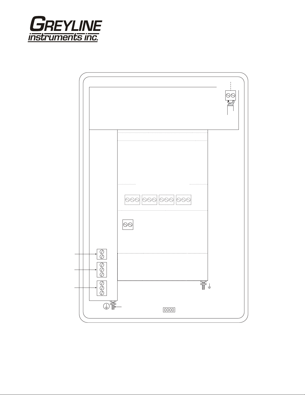
CONNECTIONS
OCF 5.0 Open Channel Flow Monitor
DATA LOGGER
SENSOR
SHLD
CORE
GRN
WHT
EXTRA RELAYS OPTION
4-20mA
RLY2
RLY1
NC
RLY3
AC
LN
–
+
NO
C
NC
NO
C
NC
AC
GND
NC
C
POWER
INPUT
C
NO
NO
RLY4
HEATER OPTION
USB HARNESS
CONNECTOR
NC
RLY5
NC
C
NO
C
RLY6
NO
GND
Page 5
Page 6
OCF 5.0 Open Channel Flow Monitor
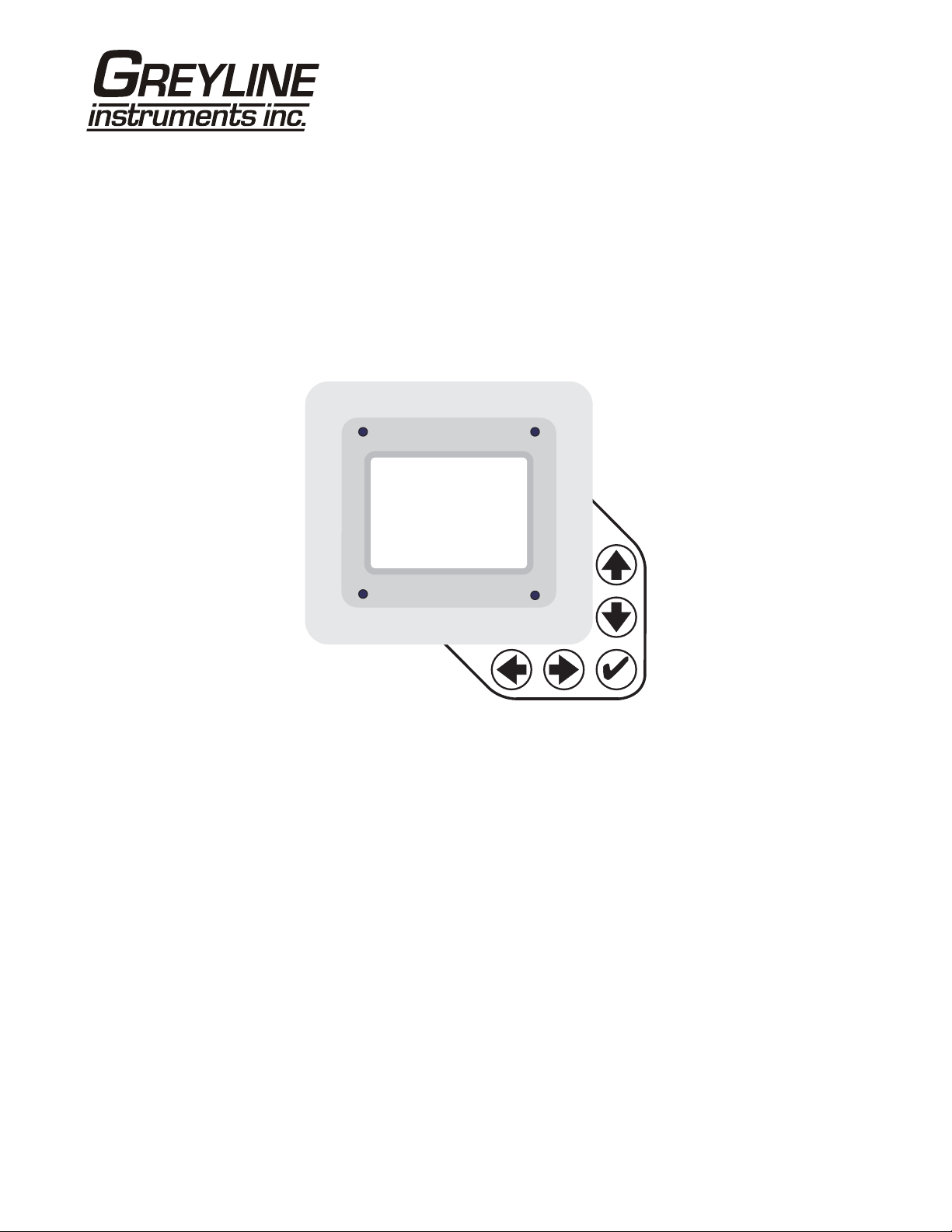
KEYPAD SYSTEM
The OCF 5.0 uses a menu system. Arrows show the four directions to leave a menu box. Press a key to
move to the next item in the direction shown. Move the cursor (highlighted) under numerals and
increase or decrease numerals with the and keys.
To store calibration values permanently (even through power interruptions), press .
Page 6
Page 7
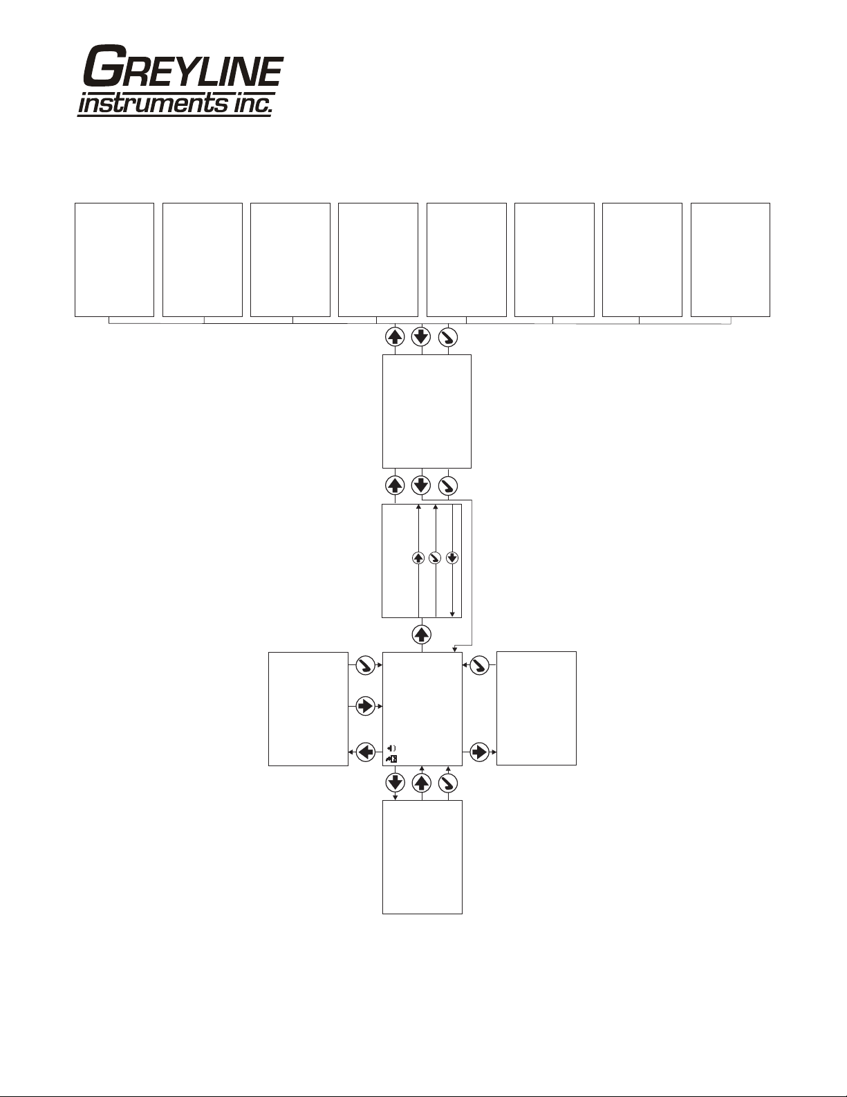
CALIBRATION MENU
OCF 5.0 Open Channel Flow Monitor
Linear ft
Volume USG
Time min
Temperature C
Mode} Flow
--Units/Mode--------
--Calibration-------
Max Range 12.000ft
Damping 10%
Min Range 1.000ft}
LOE Time 30sec
Size 22.5°
Type V-notch}
-- ----Channel Setup--
FlowFunction
8000 USG/mOff
10000 USG/mOn
Mode Pump
LOE mode Off
Relay 1}
--Relay Parameters--
Alternate No
--Data Logging-------
SetupChannel
Calibration
Relay Parameters
Units / Mode}
--Menu Selections----
Password 0000
--Password----------
May 30 13Set Date /20
Mode Flow
Set Time 14:24:40
Interval 30sec
Log Site ID 0}
Data Logging
Special Functions
Log NO
Simulation
Configuration
Analog Out 4-20mA
Backlight High
Reset Totalizer NO
Restore Defaults NO
Language English}
--Special Functions-
New Password 0000
--Simulation--------
Flow 4.004-20mA
Flow /m250USG
Relays 1 2 3 4 5 6
} Test Actual
24Logger 1. T
25.01
1.}
Sonar 1.14
Relays 2
Analog Out 1
Utility
--Configuration-----
USG/m
0.000
Data log Stopped
Log Used 0%
Sensor Good
Temperature 21C
--Message-----------
Date Feb. 12/20} 13
--24 hr log----------
Page 7
Tot 20130.8 USG
Relays 1 2 3 4 5 6
9:15:00Min Time
11:08:00Max Time
50138 USGTotal
52.20 USG/mMaximum
0.000 USG/mMinimum
34.82 USG/mAverage
EC 100%
Relays 1 2 3 4 5 6
Range 1.00ft}
Tot 0.000ft³
--Status------------
Page 8

ICONS
OCF 5.0 Open Channel Flow Monitor
1. 2.
1.
1.
2.
2. 3.
4.
Message waiting. Press .Ç
Data logging .off
Data logging .on
USB file download.
File download completed.
Download Error.
1.
3.2.
Echo OK.
No Echo .
Page 8
Page 9
OCF 5.0 Open Channel Flow Monitor
USG/m
0.000
Tot 20130.8 USG
Relays 1 2 3 4 5 6
--Message----------Data log Stopped
Log Used 0%
Sensor Good
Temperature 21C
--Status------------
Range 1.00ft
}
Tot 0.000ft
EC 100%
Relays123456
--24 hr log---------Date Feb. 12/2010
}
Total 50138 USG
Average 34.82 USG/m
Maximum 52.20 USG/m
Max Time 11:08:00
Minimum 0.000 USG/m
Min Time 9:15:00
MAIN DISP LAY
The main display shows the units selected from the Units/Mode menu, Level,
Range, Flow, HRT, and Volume rate being measured, TOTALIZER and RELAY
states. The OCF 5.0 will start-up with this display.
MESSAGE ICON
Press from the main display to view status of the data logger and error/warning
messages provided by the instrument. The Message Icon will appear on the main
display if error messages are being generated by the instrument. Refer to the
manual section Error/Warning Messages for a description. Press to return to the
main display.
STATUS
³
Press from the main display to view instrument status. Range will be displayed
in linear units.
Tot Displays the current totalizer reading.
EC Displays echo confidence.
Relays Energized relays will display as a white character on a black
background.
24 HR LOG
Press from the main display to view a formatted flow report from instruments
with a built-in data logger. Press to scroll down one day or repeatedly to scroll
to a specific date. Up to 365 days can be stored. Newest date will overwrite the
oldest. Press to return to the main display.
Page 9
Page 10

OCF 5.0 Open Channel Flow Monitor
--Password----------
Password 0000
PASSWORD
The
Password (a number from 0000 to 9999) prevents unauthorized access
to the
Calibration menu.
From the Main display press to get to
password is 0000 and if it has not been changed press the to proceed to the
Menu Selections screen.
If a password is required, press to place the cursor under the first digit and or
to set the number, then to the second digit, etc. Press or to proceed to
the
Menu Selections screen.
A new password can be stored by going to
Password
.
Password. Factory default
Special Functions/New
Page 10
Page 11
OCF 5.0 Open Channel Flow Monitor
--Units/Mode-------Mode Flow
}
Linear ft
Volume USG
Time min
Temperature C
--Units/Mode--------
Mode Flow
Linear} in
--Units/Mode--------
}Volume USG
ft3
bbl
IMG
USMG
--Units/Mode-------Temperature} C
ft
mm
m3
IG
UNITS/MODE
From
Flow, HRT or Volume.
Mode press the and then the or to select Level, Range,
Range displays distance from the sensor to the target or liquid surface like a
tape measure. Range mode is useful to measure the exact distance
from the sensor to the zero level during calibration.
Level used to measure tank level in linear units, or "Head" in an open
channel for comparison with flow tables.
m
Volume displays tank inventory in engineering units.
HRT select Horizontal Round Tank mode to calculate and display volume
units in a horizontal round tank.
Flow calculates open channel flow through a flume or weir.
L
Volume, HRT or Flow gives the additional choice of volumetric units:
ft3 - cubic feet
USG - US gallons
USMG - US million gallons (FLOW only)
IG - Imperial gallons
F
IMG - Imperial million gallons (FLOW only)
m3 - cubic meters
L - liters
bbl - U.S. oil barrel
Press to store the selection, then to the next menu item and to enter.
Linear press and then or to select units of measurement.
Press to store the selection.
Time press and then or to select day, hr, min or
sec.
Temperature press and then or to select C or F (Centigrade or
Fahrenheit).
Press or to return to the Menu Selections screen.
Page 11
Page 12

OCF 5.0 Open Channel Flow Monitor
--Calibration------Min Range 1.000ft
}
Max Range 12.000ft
Damping 10%
LOE Time 30sec
CALIBRATION
Press to
Calibration and to enter. Use or to position before
each menu item and to enter. When settings are completed press to store and
return to the Calibration menu.
Min Range Distance from the sensor face to highest expected level.
Max Range Distance fro m sensor to Zero level.
MaxVol For Volume and HRT mode only. Enter the maximum volume of
the vertical or horizontal tank.
Damping Minimum damping allows fast response to level changes.
Increasing damping slows the OCF 5.0's response to level changes
and is ideal to smooth the display and outputs in turbulent
conditions. Damping value is shown in percent (0-99%). Some
experimentation may be required to select the optimum damping
value. A value of 1% is recommended for most applications and for
fast level changes (up to ½ inch/sec - 13 mm/sec).
LOE Time Press and or to change the number of seconds without
receiving an echo before the OCF 5.0 displays ECHO LOSS, and
Control relays change state as calibrated under Relay Parameters.
Factory default is 30 seconds and is recommended for most
applications, Minimum is 1 second and maximum is 99 seconds.
Press to return to Menu Selections.
Page 12
Page 13
OCF 5.0 Open Channel Flow Monitor
PAL MER BOWLUS
MAX LEVEL
V-NOTCH
ZERO LEVEL
SENSOR
SENSOR
MIN
RANGE
MAX LEVEL
MAX
RANGE
ZERO LEVEL
MIN
RANGE
MAX
RANGE
CALIBRATION
- for Open Channel Flow
1. Before starting the calibration determine:
a) MAX RANGE = ____________________
(Maximum range = distance from the Sensor to Zero flow point)
b) MAX LEVEL = ____________________
(Maximum level of flow through flume or weir)
c) MIN RANGE = __________________
(Distance from sensor to Max Level)
Minimum range = MAX RANGE - MAX LEVEL
(must be at least 8" / 20.3 cm depending on sensor model).
2. Check the maximum range with the sensor installed by:
a) When liquid is at zero level press to view the
Status menu. Use this range measured by the OCF 5.0 as the Max
Range
setting.
Range reading in the
or
b) Carefully measure distance from sensor to zero level with a tape measure,
and use this measurement as the
NOTE
: The OCF 5.0 will not detect targets beyond user entered Max Range.
Max Range setting.
Page 13
Page 14

CHANNEL SETUP
OCF 5.0 Open Channel Flow Monitor
--Channel Setup-----Type V-notch
}
Rect Weir w/EC
Trapezoidal
Leopld-Lagco
Palmer Bowlus
--Channel Setup-----Type V-notch
}
Size 22.5
--Channel Setup-----Type Rect Weir w/EC
}
Width 0.000in
--Channel Setup-----Type Leopld-Lagco
}
Size 36in
Custom
Khafagi
Rect Weir
Parshall
--Channel Setup-----Type Khafagi
}
Width 0.000in
120
90
60
45
30
--Channel Setup-----Type Custom
°
°
°
°
°
°
}
K 0.0000
n 0.0000
--Channel Setup---Type Rect Weir
}
Width 0.000in
--Channel Setup-----Type Trapezoidal
}
Size Extra large 60
Large 60
Small 60
12in 45 SRCRC
°
2in 45 WSC
°
8in 60
°
°
°
°
30in
24in
18in
12in
10in
8in
6in
--Channel Setup-----Type Palmer Bowlus
}
Size 48in
42in
36in
30in
27in
24in
21in
18in
15in
12in
10in
8in
6in
4in
--Channel Setup-----Type Parshall
}
Size 12ft
10ft
8ft
6ft
5ft
4ft
3ft
2ft
18in
12in
9in
6in
3in
2in
1in
Page 14
Page 15

OCF 5.0 Open Channel Flow Monitor
--Relay Parameters-Relay 1
}
Function Flow
Mode Pump
On 10000 USG/m
Off 8000 USG/m
LOE mode Off
Alternate NO
--Relay Parameters-Relay 1
}
Function Temperature
On 0.0C
Off 9.0C
--Relay Parameters-Relay 1
Function Pulse
On 10.000ft}³
--Relay Parameters-Relay 1
}
Function Level
Mode Pump
On 12.000ft
Off 3.000ft
LOE mode Off
Alternate NO
RELAY PARAMETERS
Relay Press and or to select a relay (2 relays are standard, 4
additional are optional).
Function Press or to select Off, Temperature, Pulse
or
Flow.
Temperature Air temperature at the sensor location.
Press and and set the relay On and
Off for specific temperatures.
Pulse Press and set digits to the flow volume
increment required between relay pulses.
Use this feature for remote samplers,
chlorinators or totalizers. Minimum time
between pulses is 2.25 seconds and pulse
duration is 350 milliseconds.
Flow Press to Mode and to select
Pump, Low Alarm or Hi
Alarm
.
Note:
Function setting Flow will change according to selections made
under
Units /Mode eg Level, Range, Volume or HRT.
Press to return to
Menu Selections.
LOE Set relay state for ‘echo loss’ event (On, Off or Hold)
Alternate Pumps can be set to alternate when in pump mode.
Page 15
Page 16

OCF 5.0 Open Channel Flow Monitor
--Data Logging------Log Site ID 00
}
Mode Level
Set Date Feb 18/2008
Set Time 11:27:40
Interval 10sec
Log Start
Mar 19/2009
12:28:41
99
Range
Flow
HRT
Volume
60min
30min
15min
10min
5min
2min
1min
30sec
Stop
Delete
DATA LOGGING
Setup
Select Data Logging from Menu Selections.
Log Site ID
Enter a number from 00 to 99. The site ID will
become part of the downloaded file name to help
distinguish downloads from different instruments. Press
to store the setting.
Mode
Select Level, Range, Flow, HRT and
Volume. Flow (e.g. USGPM or l/sec). Press to
store the setting.
Set Date
Press or to scroll and select Month, Day and Year.
Press to store the setting.
Set Time
Press or to select the current time in Hours, Minutes
and Seconds. Press to store the setting.
Interval
Press or to select the logging interval. Flow rate
reading will be stored at each time interval. Press to
store the setting.
Note: Press to Log and or to Delete and to
delete the log file. Press and or to Start and to
restart the logger.
Log
, Start or Delete the log file. Delete old
Stop
file and start a new log to apply any changes that have
been made to the
Interval.
Log Site ID, Mode or
RETRIEVE LOG FILE
Plug a USB Flash Memory Drive (not supplied by Greyline) into the USB output
cable from the instrument. The instrument display will show the USB file
download icon until the log file is transferred to the memory card and then display
file download completed icon. The USB flash drive may be removed.
Download file names will appear in this format:
OCF__00A.LOG
MODELTAGDOWNLOAD
Page 16
Page 17

OCF 5.0 Open Channel Flow Monitor
Tag is set according to the Log Site ID entered in the instrument Data Logging
menu.
Download letter will be A for the first download from an instrument. B for the
second, then C etc. At the letter Z a - character will appear indicating that the
maximum number of downloads for that instrument are on the USB flash drive.
Older files can be erased or moved from the flash memory drive or a new memory
drive can be used.
OPENING LOG FILES
Install Greyline Logger on your PC or laptop. Refer to the Help menu in the
program for detailed instructions.
Select File/Open/Instrument Log (.log) to open the log file from your USB flash
drive.
Page 17
Page 18

OCF 5.0 Open Channel Flow Monitor
--Special FunctionsLanguage English
}
Analog Out 4-20mA
Backlight High
Reset Totalizer NO
Restore Defaults NO
New Password 0000
--Special Functions-
Language English
}Backlight High
Medium
Low
Key Hi/Lo
Key High
Key Med
Key Low
Off
SPECIAL FUNCTIONS
Language Select English, French or Spanish and
press .
Analog Out Select 4-20mA or 0-5V mode for the analog output.
Backlight Select High, Medium or Low for continuous
backlight.
Select
minute) after a keypress and then
Key Hi/Lo for high backlight (for 1
Lo backlight
until a key is pressed again.
Select
Key High, Med or Low for backlight
after a keypress and then backlight off until a key is
pressed again.
Reset Totalizer Press and select Yes to erase and restart the
totalizer at zero.
Restore Defaults Select Yes and press to erase all user settings
and return the instrument to factory default settings
New Password Select any number from 0000 to 9999 and press .
Default setting of 0000 will allow direct access to the
calibration menus. Setting of any password greater
than 0000 will require the password to be entered to
access the calibration menus.
Press to return to
Menu Selections.
Page 18
Page 19

OCF 5.0 Open Channel Flow Monitor
--Simulation-------Test Actual
}
Flow 250USG/m
4-20mA Flow 4.00
Relays 1 2 3 4 5 6
SIMULATION
Exercises the 4-20mA (0-5V) output, digital display and control relays.
Test Select Maximum and press to simulate maximum Flow, Range or
Level and to output 20mA (5V) to the analog channel.
Select
Minimum and press to simulate minimum Flow, Range or
Level and to output 4mA (0V) to the analog channel.
To simulate an intermediate Flow, Range or Level set
Actual and then enter a value for the Flow, Range or
Level. The analog output and control relays will respond to the
simulated value.
Test to
Page 19
Page 20
SENSOR MOUNTING METHODS
Notes:
1. Use the ¾" NPT"Isolation
Coupling" supplied and
only. Do not clamp sensor
tighten
body or stem.
2. Locate the sensor 1 ft (30 cm) from
the sidewall or obstruction for every
10 ft (3 m) depth.
3. mount in direct sunlight.
Do not
4. Extend sensor cable upto500 ft
(150 m) with RG62AU coaxial only.
CROSS BAR MOUNT
CLAMP
DO NOT
CLAMP IN
THIS AREA
hand
3/4"
CONDUIT
ISOLATION
COUPLING
(SUPPLIED)
MUST BE
USED
FLANGE MOUNT
4" OR6"BLIND FLANGE
TAPPED ¾" NPT
¾" NPT
NIPPLE
DO NOT
CLAMP IN
THIS AREA
OCF 5.0 Open Channel Flow Monitor
FLEXIBLE
CONDUIT
JUNCTION
BOX
(OPTION JB)
ISOLATION
COUPLING
(SUPPLIED)
MUST BE
USED
CONDUIT MOUNT
3/4"
CONDUIT
STANDPIPE LENGTH
ASSHORT AS POSSIBLE
STANDPIPE DIAMETER
AS LARGE AS POSSIBLE
TYPICAL STANDPIPE:
4” / 100 mm DIAMETER
12” / 300 mm LENGTH
NARROW DIAMETER
STANDPIPES (<4” / 100 mm)
MAY A FFECT ACCURACY
OF READING
STAND PIPE MOUNT
SMOOTH
GRIND OR FILE
PIPE EDGE
DO NOT
CLAMP IN
THIS AREA
3/4" NPT
DO NOT
CLAMP IN
THIS AREA
ISOLATION
COUPLING
(SUPPLIED)
MUST BE
USED
ANGLE MOUNT
NIPPLE
ISOLATION
COUPLING
(SUPPLIED)
MUST BE
USED
Page 20
Page 21

OCF 5.0 Open Channel Flow Monitor
SENSOR MOUNTING/LOCATION
- Open Channel Flow Applications
Each sensor is equipped with a 3/4 inch isolation coupling which MUST be used in your installation. A
threaded nipple or length of conduit may be used to position the sensor at the desired height. The sensor
should be hand-tightened by turning the sensor stem only. DO NOT use a wrench and do not over
tighten.
IMPORTANT: Follow the flume manufacturer’s directions for sensor location. The sensor should be
centered above the flume approach section and mounted 8"/203 mm (minimum) above the maximum
liquid level (depending on sensor model).
The sensor should be protected from physical damage and the sensor cable should be routed in a
separate metal conduit.
Because the sensor is equipped with a temperature sensor, it should be shielded from direct sunlight.
Use the PVC “isolation coupling” supplied with the sensor and hand-tighten the sensor/coupling
assembly onto your mounting stand. Do not clamp directly to the sensor or to the isolation coupling.
METAL CONDUIT
TO ENCLOSURE
12"
305
305 mm
12"
Page 21
Page 22

OCF 5.0 Open Channel Flow Monitor
TYPICAL SENSOR POSITIONING
FOR FLUMES AND WEIRS
Always refer to the flume or weir manufacturer’s instructions for correct measurement point upstream
from the flume or weir. Location of the sensor is critical for accurate flow measurement.
If manufacturer’s instructions are not available, the following guidelines are generally accepted.
1. PARSHALL FLUME:
Position the sensor at 2/3 Approach as
illustrated above. Sensor height must be
8" (203 mm) or more above the highest
water level.
2. PALMER BOWLUS FLUMES:
Position the sensor at ½ the flume
Diameter upstream from the throat of
the flume. Sensor height must be 8" (203
mm) or more above the highest water
D
level.
3. V-NOTCH WEIRS
3x MAX. HEAD
Position the sensor at 3 x maximum Head
upstream from the weir plate. Sensor height must
be 8" (20.3 cm) or more above the highest water
level.
SENSOR
POSITION
FLOW
WEIR
PLATE
STILLING WELLS
Stilling wells are recommended to reduce the effects of turbulence as water flows through the flume or weir. The
OCF 5.0 sensor is centered over the stilling well. Sensor height must be 8" (203 mm) or more above the highest
water level. The well must be kept clean of sediment and deposits on the side walls.
Page 22
Page 23

OCF 5.0 Open Channel Flow Monitor
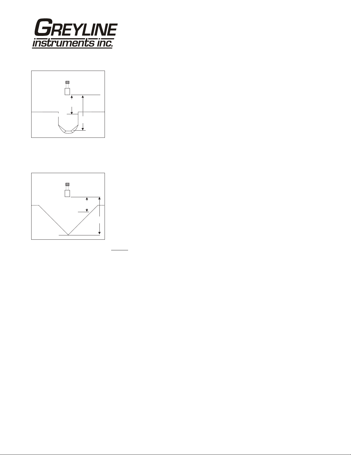
ZERO POSITIONING OF SENSOR
- Open Channel Flow Applications
Locate the sensor at the position upstream from the throat of the flume or weir plate as recommended by
the manufacturer. A technique for accurate sensor height adjustment is shown:
Page 23
Page 24

OCF 5.0 Open Channel Flow Monitor
ENCLOSURE INSTALLATION
Locate the enclosure within 20 ft (6 m) of the sensor (500 ft -150 m optional). The enclosure can be wall
mounted with the four mounting screws (included) or panel mounted with Option PM Panel Mount kit
from Greyline Instruments.
Avoid mounting the enclosure in direct sunlight to protect the electronics from damage due to
overheating and condensate. In high humidity atmospheres, or where temperatures fall below freezing,
Option TH Enclosure Heater and Thermostat is recommended. Seal conduit entries to prevent moisture
from entering enclosure.
NEMA4X (IP66) WITH CLEAR COVER
1. Open hinged enclosure cover.
COVER
2. Insert #8 screws (supplied) through the four enclosure mounting holes
to secure the enclosure to the wall or mounting stand.
Additional conduit holes can be cut in the bottom of the enclosure when
ENCLOSURE
MOUNTING
HOLES
required. Use a hole saw or Greenlee-type hole cutter to cut the required
holes.
DO NOT make conduit/wiring entries into the top of the enclosure.
ENCLOSURE
Note: This non-metallic enclosure does not automatically provide
END VIEW
grounding between conduit connections. Grounding must be provided as part of the installation. Ground
in accordance with the requirements of the National Electrical Code. System grounding is provided by
connecting grounding wires from all conduit entries to the steel mounting plate or another point which
provides continuity.
CLEANING
Cleaning is not required as a part of normal maintenance.
Page 24
Page 25

ERROR/WARNING MESSAGES
OCF 5.0 Open Channel Flow Monitor
ECHO LOSS
- or -
ECHO TOO CLOSE
SENSOR OPEN
SENSOR SHORTED
No valid echoes received within the LOE TIME setting. The OCF 5.0 will hold the
display and outputs at the last reading until a new echo is received.
Your choice of Units exceeds 9,999,999. Use USMG/d, IMG/d or m3/d so
that Units will be 9,999,999 or less
Indicates that the target is less than Min Range distance from the sensor (too
close to the sensor).
Instrument has detected sensor connection/cable Open.
Instrument has detected sensor connection/cable Shorted.
Page 25
Page 26

OCF 5.0 Open Channel Flow Monitor
FIELD TROUBLESHOOTING
SYMPTOMS
Display - full scale A
- zero B
- erratic - random C
- drifting up D
- drifting down E
ECHO LOSS prompt - flashing F
Calibration Non-Linear H
SYMPTOMS
Unit “See’s” Wrong Target Due To:
A - sensor cover not removed - remove protective cover after installation
A,C,D,F - sensor not aimed correctly
A,D,F - dust/dirt buildup on sensor - clean carefully (do not scratch sensor face)
A,D,F - condensation on sensor - lower Sensor
A,D - sensor mounting stand pipe
C,E - very turbulent flow in open channel
C,E - very turbulent level in tank - increase
Unit Picks-Up Interference Due To:
A,C - noise from high pressure fill - install submerged fill pipe
A,D - sensor coupling over tightened - hand tighten only (like a light bulb)
A,D - sensor coupling not used - use coupling supplied
C - other ultrasonic unit in close proximity - synchronize
Electrical interference:
C - sensor cable connections reversed
C - through sensor cable - use properly grounded metal conduit
FAULTS SOLUTIONS
- too long / - too narrow
- dirty / - gasket intruding
CHECK
- insulate sensor mounting location
- increase
menu) by 1-3” / 2.5-7.5 cm
- wipe sensor face and body with Rain-X
- lower Sensor below stand pipe intrusion
- increase
- install stilling well on flume or weir
- change tank fill method
Min Range (CALIBRATION
Damping (CALIBRATION menu)
Damping (CALIBRATION menu)
Page 26
Page 27

OCF 5.0 Open Channel Flow Monitor
C - sensor cable extended and junction not
insulated
C - through enclosure - use metal enclosure
C - through 4-20mA output cable - use shielded twisted pair (shielded to AC ground)
C - wiring or installation close to variable
speed drive or inverter
Unit Receives No Return Echo Due To:
C,F,E - foam on liquid surface - use stilling well (open channel flow)
B - target beyond
F - sensor damaged - remove sensor from mounting and aim at a flat,
F - sensor misalignment - check with a level
Wiring Problems Due To Sensor Cable:
A,C,F, - open circuit
B,F - short circuit - check connections/continuity (8850 ohms min.)
F - too long (max 500 ft., 150 m)
C - bundled/run in conduit with power cable
C - sensor ground shorted to conduit/enclosure
A - extended with wrong type of wire - use RG62A/U coaxial only
C - close to high voltage/large motors
C - AC chassis/ground missing on instrument
power connections
Non-Linearity Due To:
H - vapour - dissipate fumes, Calibration in-situ
H - zero not set accurately - see “Zero Positioning of Sensor”
H - wrong flume, or K&n selected (
mode)
- temperature measurement inaccuracy - install sensor sunscreen
Max Range - recalibrate
FLOW
- Use metal Junction Box
- use grounded metal conduit
- follow V.S.D. manufacturer’s instructions for Drive
grounding, wiring and shielding
stable target to test
- check connections/continuity (8850 to 12700 ohms
max./-30°C to +70°C )
- insulate
- select correct flume
- mount sensor closer to flow
Page 27
Page 28
OCF 5.0 Open Channel Flow Monitor
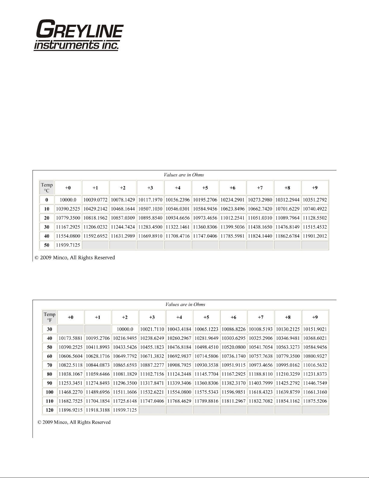
PZxx Series Sensors
Troubleshooting
Resistance measured (between the shield and center wire) across the coaxial cable ends by mulitmeter
indicates ambient temperature.
Resistance vs. Temperature
Page 28
Page 29

FUSE REPLACEMENT
1. Turn OFF power.
2. Loosen cover screw and open.
3. Remove power module.
4. Locate fuse on Power Board.
5. Replace fuse with 2 AMP/ 250V, 5 x 20mm fuse.
6. Reinstall power module into chassis.
OCF 5.0 Open Channel Flow Monitor
Fuse
POWER MODULE
Page 29
Page 30

OCF 5.0 Open Channel Flow Monitor
APPLICATIONS HOTLINE
For applications assistance, advice or information on any Greyline Instrument contact your Sales
Representative, write to Greyline or phone the Applications Hotline below:
United States: Tel: 315-788-9500 Fax: 315-764-0419
Canada: Tel: 613-938-8956 Fax: 613-938-4857
Toll Free: 888-473-9546
Email: info@greyline.com
Web Site: www.greyline.com
Greyline Instruments Inc.
Canada USA:
16456 Sixsmith Drive 105 Water Street
Long Sault, Ont. K0C 1P0 Massena, NY 13662
Page 30
Page 31

OCF 5.0 Open Channel Flow Monitor
PRODUCT RETURN PROCEDURE
Instruments may be returned to Greyline for service or warranty repair.
1) Obtain an RMA Number from Greyline -
Before shipping a product to the factory please contact Greyline by telephone, fax or email to obtain an
RMA number (Returned Merchandise Authorization). This ensures fast service and correct billing or
credit.
When you contact Greyline please have the following information available:
1. Model number / Software Version
2. Serial number
3. Date of Purchase
4. Reason for return (description of fault or modification required)
5. Your name, company name, address and phone number
2) Clean the Sensor/Product -
Important: unclean products will not be serviced and will be returned to the sender at their expense.
1. Rinse sensor and cable to remove debris.
2. If the sensor has been exposed to sewage, immerse both sensor and cable in a solution of 1 part
household bleach (Javex, Clorox etc.) to 20 parts water for 5 minutes. Important: do not immerse open
end of sensor cable.
3. Dry with paper towels and pack sensor and cable in a sealed plastic bag.
4. Wipe the outside of the enclosure to remove dirt or deposits.
5. Return to Greyline for service.
3) Ship to Greyline -
After obtaining an RMA number please ship the product to the appropriate address below:
Canadian and International USA
Customers: Customers:
Greyline Instruments Inc. Greyline Instruments Inc.
16456 Sixsmith Drive 204 150th Avenue
Long Sault, Ont. K0C 1P0 Madeira Beach, FL 33708
RMA# RMA#
Page 31
Page 32

LIMITED WARRANTY
_____________________________________
Greyline Instruments warrants, to the original purchaser, its
products to be free from defects in material and workmanship for a
period of one year from date of invoice. Greyline will replace or
repair, free of charge, any Greyline product if it has been proven to
be defective within the warranty period. This warranty does not
cover any expenses incurred in the removal and re-installation of
the product.
OCF 5.0 Open Channel Flow Monitor
If a product manufactured by Greyline should prove defective
within the first year, return it freight prepaid to Greyline
Instruments along with a copy of your invoice.
This warranty does not cover damages due to improper installation
or handling, acts of nature, or unauthorized service. Modifications
to or tampering with any part shall void this warranty. This
warranty does not cover any equipment used in connection with the
product or consequential damages due to a defect in the product.
All implied warranties are limited to the duration of this warranty.
This is the complete warranty by Greyline and no other warranty is
valid against Greyline. Some states do not allow limitations on how
long an implied warranty lasts or limitation of incidental or
consequential damages, so the above limitations or exclusions may
not apply to you.
This warranty gives you specific legal rights, and you may also
have other rights which vary from state to state.
Greyline Instruments Inc.
Page 32
Page 33

OCF 5.0 Open Channel Flow Monitor
APPENDIX A - OPTIONS
EXTRA SENSOR CABLE - OPTION XC
Each Greyline level instrument includes 25 ft. (7.6 m) RG62AU coaxial cable. Additional RG62AU
coaxial cable and Cable Junction Box (Option JBX) may be installed to extend cable up to 500 ft (152m)
as required during installation. No adjustment is required when the sensor cable is extended or
shortened. Use only RG62AU (or RG62U) coaxial cable which is available from Greyline Instruments
or your local distributor. Nominal impedance of RG62AU cable is 93 ohms.
Extended sensor cable maybe installed in metal or plastic conduit. Recommended installation with a
junction box is illustrated below:
25 ft (7.6 m) RG62AU
COAXIAL CABLE TO SENSOR
MAXIMUM 500 ft (150 m) EXTENDED
RG62AU COAXIAL CABLE TO ELECTRONICS
JUNCTION BOX - OPTION JBX
NEMA4X (IP66) polycarbonate Junction Box with terminal strips is available from Greyline
Instruments. Includes compression fittings for watertight coaxial cable entries.
DIMENSIONS
OPTION JBX - JUNCTION BOX
Mounting
.00 mm78
3. "07
2.362"
60.00 mm
3.90 mm
0.153"
2.244"
57.00 mm
90.00 mm
3.543"
Page 33
90.00 mm
3.543"
Page 34

OCF 5.0 Open Channel Flow Monitor
EXTENDED SENSOR CABLE INSTALLATION IN MANHOLE
MANHOLE COVER
JBX
ULTRASONIC
SENSOR
XC EXTENDED
SENSOR CABLE
UP TO 500 ft 152 m
CONDUITTO
ELECTRONICS
Wetwell, Sump or Pump Station
Page 34
Page 35

OCF 5.0 Open Channel Flow Monitor
SENSOR INTRINSIC SAFETY
(OPTION ISB)
When connected through Intrinsic Safety Barriers, Greyline PZ** Series sensors are certified for
installation in a hazardous location rated:
Class I, Groups C,D
Class II, Groups E,F,G
Class III
The Intrinsic Safety Barrier may be ordered with the Greyline instrument and is supplied mounted in the
Greyline instrument enclosure. Replacement barrier fuses (Part No. ISB- 011239) may be purchased
separately. The instrument enclosure containing the ISB Intrinsic Safety Barrier must be installed in a
non-hazardous location.
Page 35
Page 36

GN3SPEC-ISB-03
The intrinsic safety barrier
assemblies installed in the
OCF 5.0/SLT 5.0/PSL5.0
limit the voltage and current
supplied to the transducers
to the values listed under
‘Barrier Specifications’. To
safely install a Greyline
transducer certified for use in
hazardous locations you
must refer to the installation
drawings/specifications of
the certified transducer.
OCF 5.0 Open Channel Flow Monitor
2
1
s)
, 27 ohm
BARRIER SPECIFICATIONS
STAHL BARRIER
System Parameters
OCF 5.0/SLT 5.0/PSL 5.0
Installed in
Non-Hazardous Location
STAHL 9001/02-093-390-101
3
TRANSDUCER
GND
TRANSDUCER
CONNECTIONS
Entity Parameters
(rated 9.6V
4
V
0C
9.3V
9001/02-093-390-101
9.6V, 27 ohms
m
U
250V
Page 36
I
SC
390mA
P
0
906.8mW
C
a
4.1µF
L
a
0.16mH
Page 37

OCF 5.0 Open Channel Flow Monitor
ENCLOSURE HEATER AND THERMOSTAT - Option TH
Instruments can be factory-equipped with an Enclosure Heater and Thermostat or the module can be
customer-installed. The Thermostat is factory set to turn ON at 40°F (4.5°C) and OFF at 60°F (15.5°C).
Power consumption is 15 Watts.
TO AC POWER SUPPLY
ENCLOSURE SUNSCREEN - Option SCR
Do not mount instrument electronics in direct sunlight. Overheating will reduce the life of electronic
components and condensate may form during the heat/cool cycles and cause electrical shorts.
11"/280 mm
Note:
Exposure to direct sunlight can cause
overheating and moisture condensation
which will reduce the operating life of
electronics.
Protect Instruments from direct sunlight
with this iridite finished aluminumsun
screen (Greyline Option SCR).
Seal conduit entries with caulking
compound to further reduce moisture
condensation.
11"
280 mm
5"
127mm
Page 37
Page 38

OCF 5.0 Open Channel Flow Monitor
POWER INPUT OPTION
9-32VDC
OCF 5.0 Level & Flow Monitors may be ordered factory-configured for 9-32VDC power input.
QUICK BENCH TEST:
Connect Sensor as shown below, then Power. When properly connected figures will show on the large
LCD display. Test operation of the OCF 5.0 by holding the sensor steadily and aiming at a flat, stable
target 12 to 28" (305 to 711 mm) away from the end of the sensor. Allow a few seconds for the OCF 5.0
to lock onto the target before displaying its distance. The OCF 5.0 will now display Range in ft or cm
(factory calibration).
CONNECTIONS:
POWER INPUT: Connect 9-32VDC/0.5 Amps to the + and - terminals. The Power Input GND must be
connected to the nearest Ground pole. A 1 amp fuse in line is recommended.
SENSOR
SHLD
CORE
GRN
WHT
DATA LOGGER
EXTRA RELAYS OPTION
NC
NC
4-20mA
RLY2
RLY1
NO
C
NC
NO
C
NC
C
NO
RLY3
DC
+–
–
+
DC
GND
C
NO
RLY4
USB HARNESS
CONNECTOR
NC
RLY5
NC
C
C
NO
NO
RLY6
GND
Page 38
Page 39

OCF 5.0 Open Channel Flow Monitor
CONVERSION GUIDE
FROM TO MULTIPLY BY
US GALLONS CUBIC FEET 0.1337
US GALLONS IMPERIAL GALS 0.8327
US GALLONS LITRES 3.785
US GALLONS CUBIC METERS 0.003785
LITRES/SEC GPM 15.85
LITRES CUBIC METERS 0.001
BARRELS US GALLONS 42
BARRELS IMPERIAL GALS 34.9726
BARRELS LITRES 158.9886
INCHES MM 25.4
DEGREES F DEGREES C (°F-32) x 0.556
POUNDS KILOGRAMS 0.453
PSI BAR 0.0676
FOOT² METER² 0.0929
VOLUME CALCULATION FOR ROUND TANKS: 3.142 x R² x H
R = TANK RADIUS (½ TANK DIAMETER)
H = TANK HEIGHT
Page 39
Page 40

OCF 5.0 Open Channel Flow Monitor
SPECIFICATIONS
Accuracy: ±0.25% of Range or 2
mm, whichever is
greater Repeatability
and Linearity: 0.1% F.S.
Displays: White, backlit matrix -
displays flow rate,
totalizer, relay states,
operating mode and
calibration menu
Calibration: built-in 5-key calibrator
with English, French or
Spanish language
Power Input: 100-240VAC, 50/60Hz,
30 Watts or
9-32VDC, 9 Watts max
Output: Isolated 4-20mA (1000
ohm load max.)
Control Relays: Qty 2, rated 5 amp 240VAC SPDT, programmable flow alarm and/or
proportional pulse
Enclosure: watertight, dust tight NEMA4X (IP 66) polycarbonate with a clear
shatter-proof face
Environmental Conditions: Relative humidity up to 80% -23 to 60°C ambient temperature,
maximum 5000 m altitude, pollution degree 4, Installation Category II.
Sensitivity: adjustable. Damping: adjustable
Electrical Surge Protection: Sensor, 4-20mA output and AC power input
Approximate Shipping Weight: 10 lbs (4.5 kg)
7.4 / 188 mm"
6.46 / 164 mm"
OCF 5.0
Open Channel
Flow Monitor
CONDUIT ENTRY
LOCATION
10.94" / 278 mm
5.12 / 130 mm"
10 / 254 mm"
SIDE VIEW
Standard Sensor PZ15
Maximum Range: 15 ft (4.57 m)
Minimum Range (Deadband): 8" (203.2 mm)
Operating Frequency: 92 KHz
Beam Angle: 8°
Operating Temperature: -40° to 150° (-40° to 65°C)
Temperature Compensation: Automatic, continuous
Max. Operating Pressure: 20 psi (1.35 bar)
Sensor Face: PVC
Sensor Body: PVC
Mounting: ¾" NPT
Cable Length: 25 ft. (7.6 m) continuous
RG62AU coaxial. Optional
50 ft. (15 m) continuous
Max. Cable Length: 500 ft. (152 m) RG62AU
coaxial (splice)
Hazardous Rating: CSA rated Intrinsically Safe
Class I, Groups C,D, Class
II, Groups E,F,G with
Optional Intrinsic Safety
Barrier.
Page 40
~4.25"
(108mm)
OVERALL
3.125"
79.4 mm
25 ft (7.6 m) RG62AU
COAXIAL CABLE
(50 ft 15 mOR
100 ft 30 m )OPTIONAL
3/4“ NPT
3/4" NPT
2.1" (53 mm)
ISOLATION
COUPLING
(SUPPLIED)
1.125"
(28.6 mm)
Page 41

OCF 5.0 Open Channel Flow Monitor
Optional Sensor PZ32T
Maximum Range: 32 ft. (10 m)
Deadband (blanking): Programmable, minimum 12” (305
mm)
Beam Angle: 8° at 3 DB
Temperature Compensation: Automatic, continuous
Operating Frequency: 42 KHz
Exposed Materials: PVC and Teflon
Operating Temperature: - 40° to 150°F (-40° to 65°C)
Operating Pressure: 20 psi (1.35 Bar) maximum
Mounting: ¾” NPT (PVC isolation coupling
supplied)
Sensor Cable: RG62AU coaxial, 25 ft. (7.6 m)
standard
Hazardous Rating: with optional Intrinsic Safety Barrier:
CSA, Class I,II,III, Div. I,II, Groups
C,D,E,F,G
Note: Max Range reduced to 25 ft
(7.6 m) with ISB option.
3/4"
NPT
ISOLATION
COUPLING
(SUPPLIED)
3/4"
NPT
SIDE
VIEW
END
VIEW
PVC
PVC
1-3/4 "
44.5mm
L
TEFLON
O
TEF
25' (7.6 m) RG62AU
COAXIAL CABLE
3-7/8 "
98mm
5"
(127mm)
OVERALL
Optional Sensor PZ32TE
Maximum Range: 32 ft. (10 m)
Deadband (blanking): Programmable, minimum 12” (305
mm)
Beam Angle: 8° at 3 DB
Temperature Compensation: Automatic, continuous
Operating Frequency: 42 KHz
Exposed Materials: Teflon
Operating Temperature: -40° to 170°F (-40° to 76°C)
Operating Pressure: 20 psi (1.35 Bar) maximum
Mounting: ¾” NPT (Teflon isolation coupling
supplied)
Sensor Cable: RG62AU coaxial, 25 ft. (7.6 m)
standard
Hazardous Rating: with optional Intrinsic Safety Barrier:
CSA, Class I,II,III, Div. I,II, Groups
C,D,E,F,G,
Note: Max Range reduced to 25 ft
(7.6 m) with ISB option.
3/4"
NPT
TEFLON
ISOLATION
COUPLING
(SUPPLIED)
3/4"
NPT
SIDE
VIEW
END
VIEW
TEFLON
TEFLON
1-3/4 "
44.5mm
L
TEFLON
O
TEF
25' (7.6 m) RG62AU
COAXIAL CABLE
3-7/8 "
98mm
5"
(127mm)
OVERALL
Page 41
 Loading...