

Page 1
Area-Velocity Flow Meter
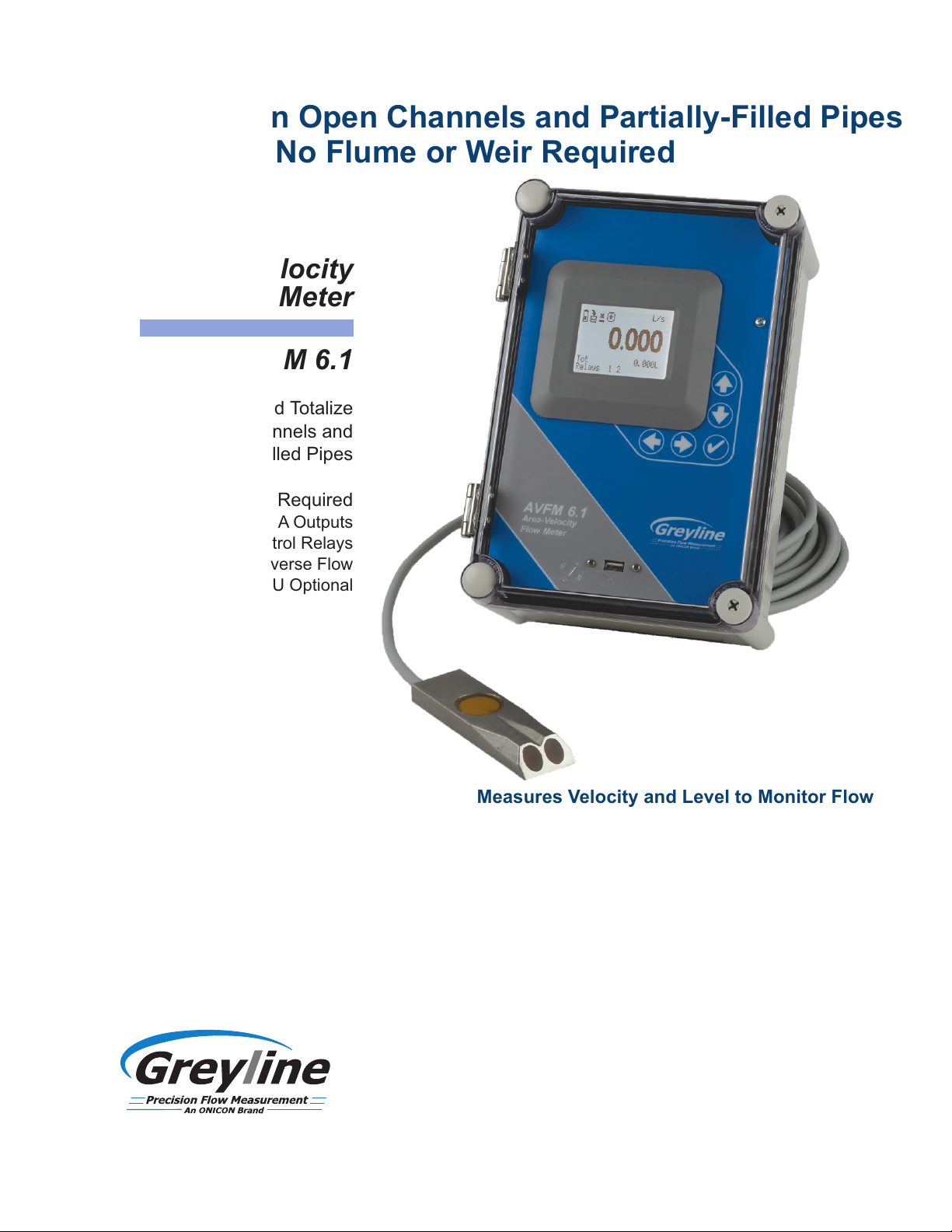
Measure Flow in Open Channels and Partially-Filled Pipes
No Flume or Weir Required
Area-Velocity
Flow Meter
Model AVFM 6.1
Display, Transmit and Totalize
Flow in Open Channels and
Partially-Filled Pipes
No Flume or Weir Required
Three 4-20mA Outputs
Two Control Relays
Measures Reverse Flow
Modbus® RTU Optional
Area-Velocity Flow Meter
Submersible Ultrasonic Sensor
Measures Velocity and Level to Monitor Flow
with a single Ultrasonic Sensor
Measure flow through open channels, partially full pipes and
surcharged pipes without a flume or weir. Ideal for wastewater
stormwater, effluent, industrial wastewater, and irrigation water.
The AVFM 6.1 uses a submerged ultrasonic sensor to continuously
measure both Velocity and Level in the channel. The sensor
resists fouling, corrosion and abrasion. The flow meter can be
configured with the standard submerged velocity-level sensor, or
with submerged velocity plus a separate non-contacting ultrasonic
level sensor, for highly aerated fluids or those with high
concentration of suspended solids.
View flow rate and total flow on the large backlit LCD display and
connect to external devices with three 4-20mA outputs and two
control relays. Flow rate, volume, run hours, and diagnostic
information available through the optional Modbus® RTU serial
communications.
Page 2

Ultrasonic Flow Monitor for
Partially Filled Pipes & Open Channels
Easy to Use
The AVFM 6.1 Area-Velocity Flow Meter
measures both Level and Velocity to
calculate flow in an open channel or pipe.
Configuration is simple: enter the pipe
diameter or channel dimensions and the
AVFM 6.1 automatically computes and
Submerged Sensor
Measures Level And Velocity
stainless steel mounting bracket (included) and a single screw into the bottom of the pipe or channel. No special
compounds, tools or hardware are required. The sensor is completely sealed with no orifices or ports.
Recommended Pipe or Channel Conditions
Careful selection of sensor mounting location results in best performance and maintenance-free operation. Avoid locations
where sediment builds up.
Best possible accuracy will result when the water is not highly turbulent and where velocity is evenly distributed across the
channel. The channel should not have drops or direction changes immediately upstream of the sensor mounting location.
Pipe or channel slope should not exceed 3%. See installation manual for specific installation recommendations.
The AVFM 6.1 can measure forward flow velocity up to 20 ft/sec (6 m/sec) and reverse flow up to 5 ft/sec (1.5 m/sec). The
electronics and software sample and average flow rates continuously to provide stable readings. The submerged
velocity/level sensor will measure flow in partially full and surcharged pipes with pressure up to 10 psi. No special set-up
or adjustment is required. Minimum recommended pipe diameter is 6” (150 mm).
displays flow volume.
The ultrasonic sensor mounts inside the
pipe or on the bottom of a channel with a
Alternate Sensor Configurations
Alternate sensor models are available for special applications: a
separate non-contacting ultrasonic level sensor with a submerged
velocity sensor. Sensor cable can be extended up to 500 ft (150 m).
Use this configuration for pipes or channels with high concentration of
air or suspended solids.
Custom Channel Shapes
Configure the AVFM 6.1 for
installation in irregular or compound channel shapes by entering the channel
width at multiple level points through a simple menu. Channels of virtually any
shape can be monitored with your choice of measurement units.
Standard 26 Million Point Data Logger
The AVFM 6.1 will store time and date-stamped
flow values at 10 second to 60 minute intervals.
Daily flow reports are automatically created where total, minimum, maximum and average
flow rates are displayed on the LCD display. Transfer log files and daily flow reports to any
USB flash drive just by connecting to the logger's USB output. Windows software is
included to display log files in graph and table formats, change measurement units and
generate flow reports. Or, download data as .csv file format for import directly to Microsoft
Excel.
VELOCITY
LOW PROFILE
NON-CONTACTING
ULTRASONIC
SENSOR
LEVEL
FLOW
Page 3

AVFM 6.1 Specifications
General Specifications
Channel Types:
Electronics Enclosure:
Accuracy:
Display:
Programming:
Power Input:
Outputs:
Control Relays:
Data Logging:
Operating Temp. (electronics):
Approximate Shipping Weight:
Approvals:
QZ02L Sensor
Velocity Measurement Range:
Level Measurement Range:
Operating Temperature:
Exposed Materials:
Sensor Cable:
Sensor Mounting:
Temperature Compensation:
Greyline AVFM 6.1 Area-Velocity Flow Monitor
Round pipe, rectangular, trapezoid, egg or custom shapes
Watertight and dust tight NEMA4X (IP 66) polycarbonate with clear, shatterproof cover
Level: ±0.25% of reading or ±0.08”, whichever is greater. Repeatability & Linearity 0.1%.
Velocity: ±2% of reading or ±0.04 ft/sec, whichever is greater. Requires solids or bubbles minimum size of
100 microns, minimum concentration 75ppm. Repeatability & Linearity 0.5%
White, back-lit matrix - displays flow rate, totalizer, relay states, operating mode and calibration menu
Built-in 5-key calibrator with English, French or Spanish language selection
100-240VAC 50-60Hz, 10VA maximum. Optional: 9-32VDC, 10 WATTS maximum
3 Isolated 4-20mA, 1000 ohm, (Flow, Level and Velocity) or 0-5VDC by menu selection
2 Relays, form 'C' dry contacts rated 5 amp SPDT; programmable for flow proportional pulse
(sampler/totalizer), flow and/or level alarm
Programmable 26 million point data capacity, time and date stamped plus formatted flow reports including
Total, Average, Minimum, Maximum and times of occurrence. Includes USB output to Flash Drives and
Windows software
-5° to 140°F (-20° to 60°C)
10 Lbs. (4.5 Kg)
CE, CSA/UL/EN 61010-1
0.1 to 20 ft/sec (0.03 to 6.2 m/sec) and reverse flow to -5 ft/sec (-1.5 m/sec) in fluids containing bubbles or
solids with a minimum size of 100 microns and a minimum concentration of 75 ppm to act as acoustic
reflectors
Minimum Head: 1 in (25.4 mm). Maximum Head: 15 ft. (4.57 m)
5 to 175°F (-15 to 80°C)
316 stainless steel, epoxy resin, polyurethane
25 Ft. (7.6 m) submersible polyurethane jacket, shielded, 3-coaxial
Includes MB-QZ stainless steel mounting bracket
Automatic, continuous
Options
Industrial Automation Protocols:
Sensor Cable:
Sensor Cable Junction Box:
Enclosure Heater:
Intrinsic Safety Barriers:
Sensors:
Sensor Mounting Bands:
Dimensions
SIDE VIEW
25 ft / 7.6 m
cable length
Modbus® RTU via RS-485
50 ft. (15 m) or 100 ft. (30 m) submersible, continuous from Sensor - or splice up to total of 500 ft (150 m)
length
Watertight NEMA4 polycarbonate with connection terminal strip
Thermostatically controlled to -40° F/C - recommended for temperatures below 32°F (0°C)
For Sensor mounting in Class I,II,III, Div. I,II, Groups C,D,E,F,G hazardous locations
Separate non-contacting ultrasonic level sensor and submerged velocity sensor
Stainless steel sensor mounting bands for pipes 6” to 72” (150 to 1800 mm) diameter
7.4 / 188 mm"
0.50"
12.7 mm
4. "92
1 mm25
0.63"
16 mm
1.50"
38.1 mm
6.46 / 164 mm"
AVFM 6.1
Area-Velocity
Flow Meter
278
/
94"
.
10
mm"
254
/
10
5.12 / 130 mm"
Q VELOCITY/LEVEL SENSORZ02L
CONDUIT ENTRY
LOCATION
SIDE VIEW
ENCLOSURE
Page 4

New Open Channel or Partially-Filled Pipe Flow Meter
Measures Velocity and Level to calculate Flow
AVFM 6.1 Area-Velocity Flow Meter
w Measure flow in pipes and open channels of
any shape
w Ideal where flumes or weirs are difficult to
install
w Works with water level from 1" (25.4 mm) to
15 ft (4.5 m)
w Auto-detects field installation of options serial
Recommended for:
] Wastewater
] Industrial Effluent
] Stormwater
] Combined Sewers
] Natural Streams
] Irrigation Water
The AVFM 6.1 Area-Velocity Flow Meter includes a submerged ultrasonic
sensor that is installed at the bottom of an open pipe or channel. Exposed
materials are stainless steel so the sensor resists fouling and corrosion. It
has no moving parts and no orifices, ports or electrodes.
The AVFM 6.1 displays and totalizes flow. It includes three 4-20mA outputs
(Flow, Level and Velocity), plus two control relays for level alarms or flow
proportionate pulse output for samplers and chlorinators. It is easy to
calibrate with the built-in keypad and menu system. A built-in 26 million
point data logger with USB output is standard. Intrinsic Safety Barriers for
sensor and cable installation in hazardous rated channels is also optional.
communications and control relays.
How to Order
Applications Support
No Risk Appraisal
The Greyline Guarantee
USA: 11451 Belcher Road South, Largo, FL 33773
Tel: 315-788-9500 / 888-473-9546 Fax: 315-764-0419
Canada: 16456 Sixsmith Dr., Long Sault, Ont. K0C 1P0
Tel: 613-938-8956 / 888-473-9546 Fax: 613-938-4857
Internet: www.greyline.com E-mail: info@greyline.com
180701Printed in Canada
Contact a Greyline sales representative in your area or phone one of our sales
engineers. Describe your requirements and receive our prompt quotation.
Take advantage of Greyline's applications experience. Phone 1-888-473-9546 for
advice and information on applications, installation or service for Greyline instruments.
The Greyline AVFM 6.1 Area-Velocity Flow Meter must meet your requirements.
Discuss your application with a Greyline representative to arrange a 30-day trial.
Quality of Materials and Workmanship - Each instrument manufactured by Greyline is
warranted against defects in materials and workmanship for a period of one year from
date of purchase. Refer to our limited warranty included with each product.
RELIABLE MEASUREMENT AND CONTROL
 Loading...