

GREAT PLANES Sportster Bipe 40 Instruction Manual
Sportster
Instruction Manual
Bipe
40
Engine size
Wingspan 45 1/2"
Wing Area
Length 41 1/2"
Weight
Materials Needed to Complete
4
Channel radio Propeller Fuel tank
Engine Wheel collars Spinner
Fiberglass cloth/resin Wheels Covering
Engine mounting bolts Hinges Instant glue
Pushrods/clevises Wing bolts EPOXY
The Sportster Bipe
vides full aerobatic maneuverability, yet has enough wing area for docile low speed capability.
The parts are machine cut and sanded for accurate fit. Should you notice a difference in size between
plans and parts, it is usually because paper changes size with moisture.
Different types of glue may be used such
glue). Build on a flat surface for straight wings and fuselage.
Please read through this step
overall idea of the construction steps and t o avoid mistakes. Use the plan and parts list to identify the var
ious parts.
40
.35-.45
716 sq
5-61/2
was designed for sport flying. This biplane design with symmetrical wings pro
.
in.
Ibs.
the
Sportster:
as
epoxy, cyanoacrylate(instant glue) and aliphatic resin (white
-by-
step instruction manual before you start building soyou will have an
-
-
This R/C kit and the model you will build is not a toy! It is capable of serious
bodily harm and property damage.
-
ALONE
gear (engine, tank, pushrods, etc.) and to test the model and fly
enced, competent help in accordance with all safety standards and common
sense as set down in the Academy of Model Aeronautics Safety Code.
gested that you join the AMA and become properly insured before you attempt to
fly this model. I F YOU ARE JUST STARTING R/C MODELING, CONSULT YOUR
LOCAL HOBBY SHOP
TO
FIND AN EXPERIENCED INSTRUCTOR IN YOUR AREA.
to build this kit correctly, properly install all R/C components and flying
OR
Academy of Model Aeronautics
1810 Samuel Morse Dr.
Reston, VA
22090
WAR
WRITE TO THE ACADEMY OF MODEL AERONAUTICS
N
IT
I
N
G
IS
YOUR RESPONSIBILITY AND YOURS
PO
BOX
!
788
URBANA
it
only
lLLlNOlS61801
with experi
It
is sug
2171367
2069
-
-
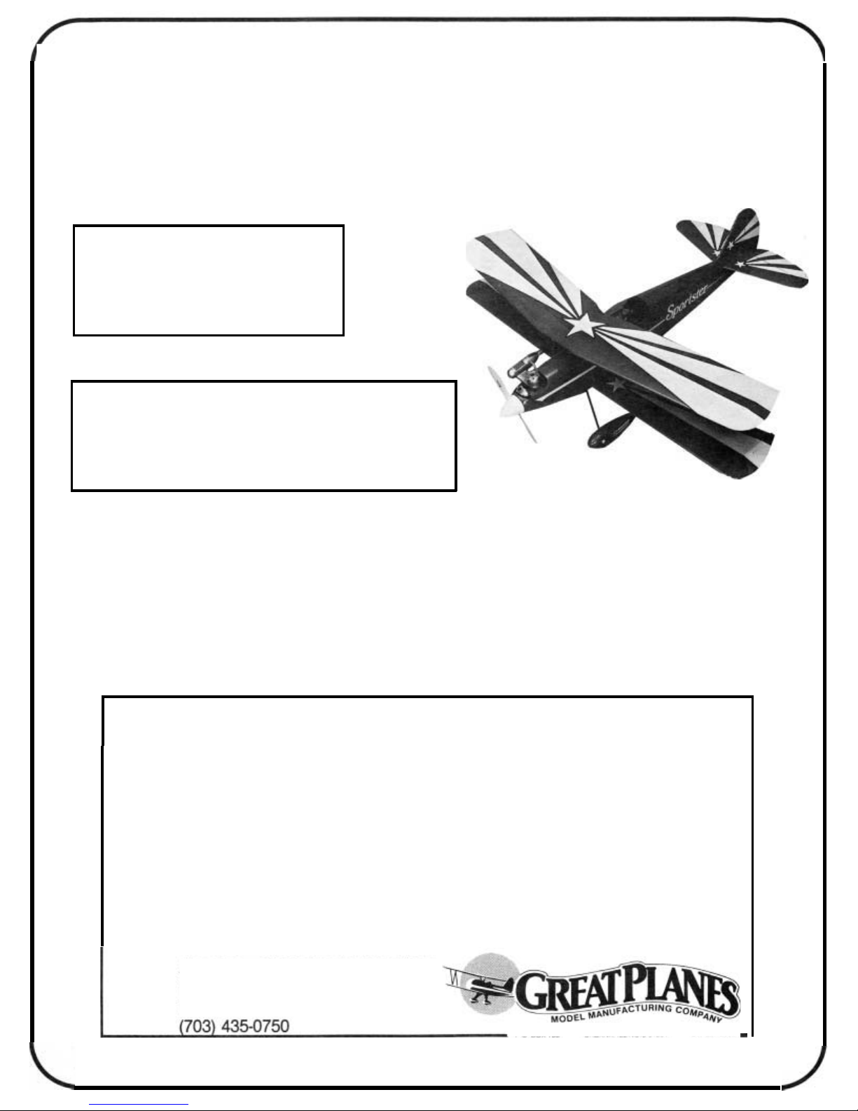
BUILDING THE TAIL
PREPARE THE FIN AND RUDDER
SECTION
Sandthe forwardand rear sectionsof the fin
sary for a good fit. Working over the plans, glue the fin section
pieces together. Sand both sides of the rudder.
CUT THE HINGE SLOTS IN THE FIN AND RUD
DER; CUT OUT RUDDER FOR JOINER CLEAR
ANCE
Draw centerlines down the trailing edge of the fin
and the leading edge of the rudder. Mark and cut the hinge
slots. Two hinges are used above the stabilizer. The third hinge
should be just below the stab and above the tail wheel strut
tab. Cut out part of the rudder leading edge for elevator joiner
wire clearance. Wait to shape the leading edge until the hole
is drilled for the tail wheel tiller arm later.
if
neces
-
-
-
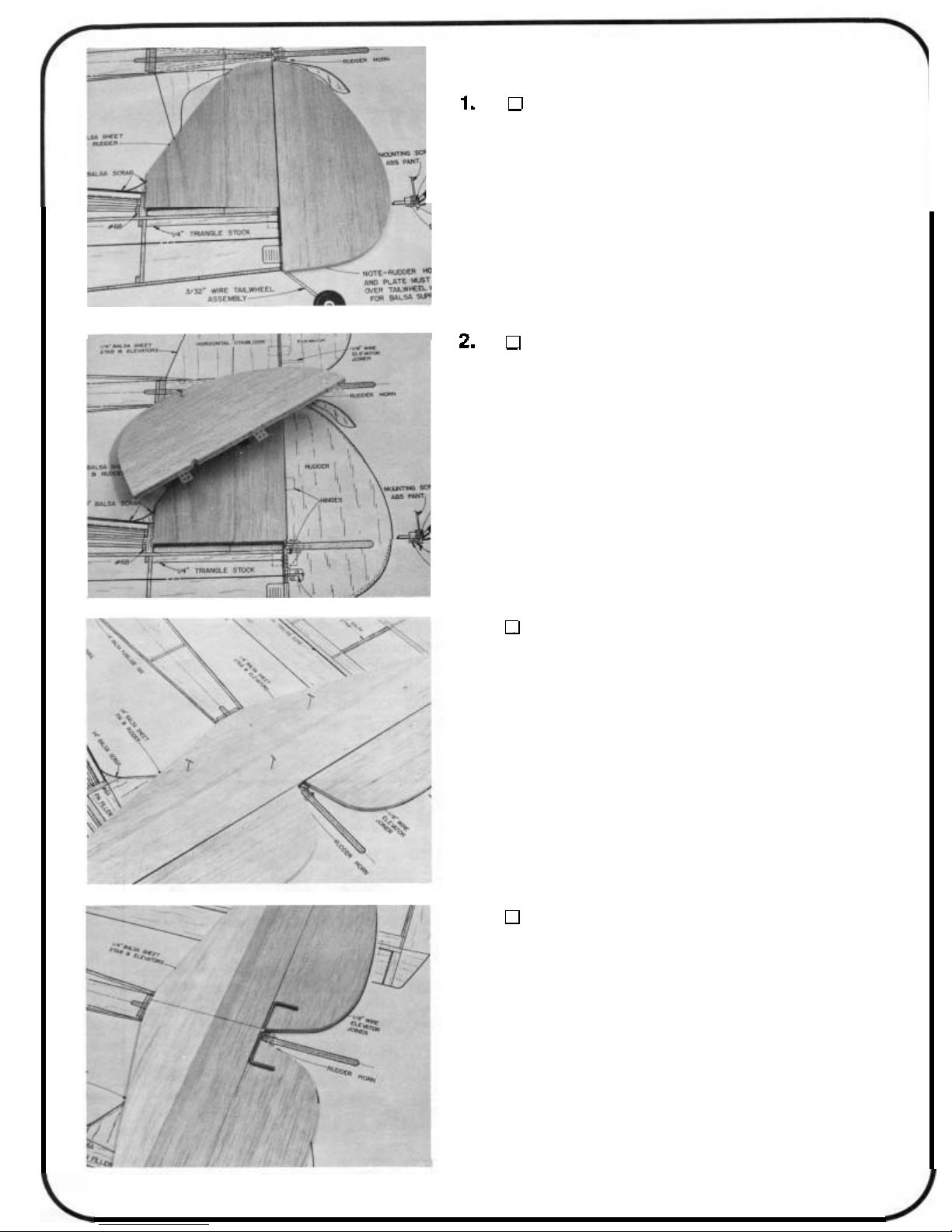
3.
the stab
sides of the stab and elevator halves.
4.
the stab and a centerlinedown the leadingedges of the elevator
halves. Mark the center of the elevator joiner wire. Align the
stab, elevator and joiner wire and mark the hole locations for
the joiner wire arms on the centerline of the elevator leading
edge. Drill the holes.
GLUE STAB PARTSTOGETHER; SAND THE STAB
AND ELEVATORS
Check the fit and sand the forward and rer parts of
so
they fit together well. Glue them together. Sand both
DRILL HOLES IN THE ELEVATOR HALVES FOR
ELEVATOR JOINER WIRE
Draw a front to back centerline down the top side of
2
5.
the hole
the leading edge of the elevator.
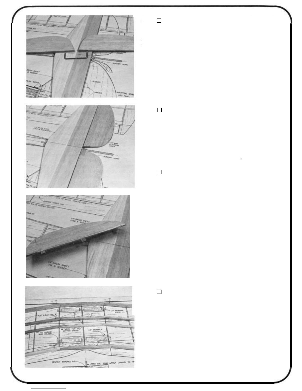
GROOVE OUT THE ELEVATORS
WIRE CLEARANCE
Cut a groove in the elevator leading edge inside of
so
when the joiner wire is installed it will be flush with
FOR
Do
both elevator halves.
JOINER
6.
elevator halves. Check to make sure that this assembly is
aligned properly. Bend the joiner arms
fit.
DO NOT GLUE THE JOINER WIRE TOTHE ELEVATOR
HALVESUNTILAFTERTHE PIECESARE COVERED LATER.
7.
halves as you did with the fin and rudder. See the plans for
locations. Shape the leading edges of the elevator halves to a
V’.
READ THIS FIRST BEFORE YOU START BUILDING THE
WING PANELS: It is very important that you build straight wings
with nowarps or twists or you will get some flying characteristics
you didn’t expect! Bevery careful when you align the ribs, spars,
leading edges, trailing edges and sheeting at the various steps
below. All these parts should be in their correct positions before
you glue them in place. Hold or pin the parts in place, then
glue. Use the following instructions to help you build the wing
straight and warp free.
TRIAL FIT THE JOINER WIRE
Temporarily install the elevator joiner wire into the
if
necessary for a perfect
CUT HINGE SLOTS FOR THE STAB AND
ELEVATOR
Mark and cut the hinge slots for the stab and elevator
Remember: Anyone can build a wing. Only
can build a straight wing.
BUILDING
Start the top wing by building twospars from 1/4 x
1/4 x 24 balsa, aleadingedge from 1/4 x1/2 x 24 balsa and
a trailing edge from1/4x
on the plan. Cut the parts, fit them together and then glue
overtheplan. The top wing is builtin one piece. You will
build the top wing upside down at first. Use epoxy when
you gluethese pieces together in this step.
3
THE
TOP
1/4 x 24
WING
balsa. U se waxedpaper
a
careful builder
2.
top wing rib. Note that the three center ribs have2 extra notches
for the cabane mounting plate. Draw rib alignment centerlines
down the back of the leading edge and the front of the trailing
edge.
PREPARE THE RIBS
Draw a rib alignment line down the center of each
3.
down) over the waxed paper covered plan. Place the ribs on
the spar. Align the ribs at the positions shown on the plans.
Make sure that the three center ribs have the cabane notches
"up"
extra 1/4 x 1/4
drew on the ribs are parallel to the building board. When the
ribs are aligned correctly, and at 90 degrees to the building
board, glue the ribs
with the line on the leading edge. Glue the ribs
edge. Line up the trailing edge line
ribs
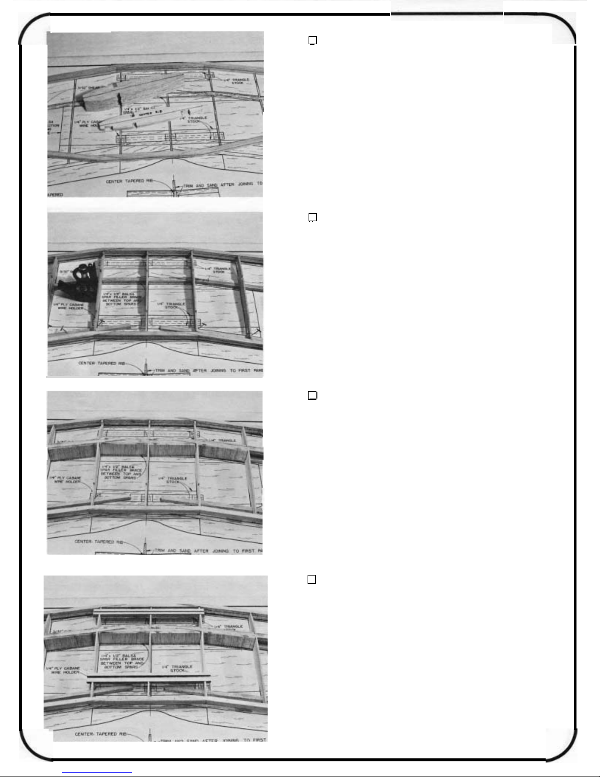
4.
two end center ribs for the 1/4 x 9/16 balsa spar filler brace.
Glue in the 1/4 x 9/16 filler brace pieces from the center rib out
past the spar scarf joint on both sides of the center rib. Glue
in the bottom spar. Now cut shear web pieces from 3/32 x 3
24 balsa to fit between the spars at the rib bays shown on the
plan. The wing should still be shimmed up with the extra spars
throughout the building process. Use epoxy in this step.
ALIGN AND GLUE RIBS, LEADING EDGE AND
TRAILING EDGE TO TOP SPAR
Pin the top spar (the wing will be built (upside
as shown. Shim up the trailing edges of the ribs with the
x
24 spars, making sure the centerlines you
to
the spar. Line up the lines on the ribs
to
the leading
to
the rib lines and glue the
to
the trailing edge.
GLUE IN SPAR FILLER BRACE, BOTTOM SPAR
AND SHEAR WEB
Cut out the area between the spar notches on the
x
I
5.
wire holders with epoxy into the slots in the htree center ribs.
Make sure the cabane holders are flush with the top edges of
the ribs.
4
ADD THE CABANE HOLDERS
Glue in the two plywood 1/4 x 1/2
x
6 1/2 cabane
6.
on the 1/16
x
24 trailing edge sheeting and the 1/16x3x15 center section
sheeting. Do not glue the sheeting
you will cut away this sheeting later. Cut cap strips from 1/16
3/16x36 balsa and glue them in place over the rib edges.
ADD THE SHEETING AND CAP STRIPS
Cut the sheeting to fit first then glue in place. Glue
x
2-1/8x24 leading edge sheeting, the 1/16x7/8
to
the cabane holders as
x
7.
down
pieces
on the plan. Glue this 1/4 tri
holder. Also cut tri stock
.
ribs on top ofthe cabane holders. Glue these braces in place.
ADD 1/4 TRI STOCK BRACES
After the glue is dry, turn the wing over and pin it
to
the building board. Use 1/4x36 triangle stock and cut
to
fit along the length of the cabane holders as shown
to
the sheeting andtothe cabane
to
fitoneither side of the three center
\
8.
the1/16
center section sheeting. Glue onthe1/16
ADDTHE REST OFTHE SHEETING
x
Glue on the1/16
x
7/8
x
24trailingedge sheeting and the 1/16x3
2-1/8x24leading edge sheeting,
x
x
3/16cap strips.
15
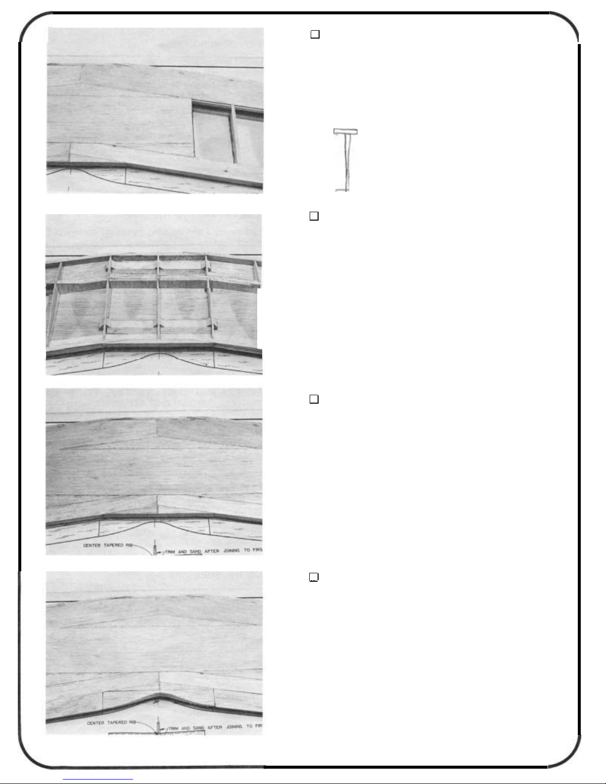
9.
andthe3/8
to
fit first and then glue them in place. Now cut the curve in the
center trailing edge as shown on the plan and in the photo.
5
ADDTHETRAILINGEDGE
x
Addthetapered3/8
x1x
6taperedcentertrailingedgepiece.Cutparts
1x24balsa trailing edgestock
BUILDING
line. Also draw centerlines down the 1/4
and the 1/4
bottom to the bottom wing at this point.
THE
PREPARE WING RIBS
Mark all bottom wing ribs with a rib alignmentcenter-
x
1/2x24 trailing edge pieces. There is no top or
BOTTOM
WING
x
1/2x24 leadingedge
2.
the left panel first. Use the extra spar as a shim at the trailing
edge as you did with the tio wing. Pin the bottom spar over the
plans. Align the ribs to the spar, shim up the trailing edges of
the ribs and glue the ribs
hold down block as a spacer for location of ribs #1 and #2.
(Note: These hold downs are the same size as the ones that
glue into the fuselage later.) Do not glue the hold down block
in place yet.
3.
(leading edge, trailing edge and top spar). Use epoxy to glue
the hold down in place. Glue the balsa 1/4
the hold down and sand the it
GLUE THE RIBS TO THE SPAR
Build the right and left wing panels separately. Build
to
the spar. Use the 1/4x7/8
ADD LEADING EDGE, TRAILING EDGE, TOP
SPAR, HOLD DOWN AND FILLER
Align the above parts first and then glue in place
x 5/8 x
to
the shapeofthe rib contour.
x
3
3
filler above
wing
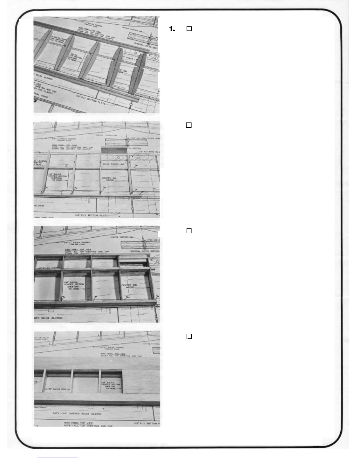
4.
ADD THE SHEETING
x
Glue on the 1/16
leading edge sheeting, the 1/16
edge sheeting and the 1/16 x 3
sheeting. Cut cap strips from 1/16
and glue them in place.
6
x 7/8 x
x
15 center section
x
2-118x24
24 trailing
3/16x36 balsa
5.
it to the board and glue in the balsa filler on the other side of
the holddown. Sand it to shape. Add the leadingedge sheeting,
the trailing edge sheeting and the center section sheeting. Add
the cap strips. This completes the left wing panel for now. Re
move the panel from the building board when it is dry. Now
build the right wing panel by following steps 1 through
ADDTHE SHEETINGAND FILLER ONTHEOTHER
OF
SIDE
When the glue is dry, turn the wing panelover, realign
THE WING PANEL
5.
INSTALLING THE WING TIPS
-
1.
Do not cut
top and bottom wingslpanels. The tips should be centered on
the tip rib and the leading edge centerline. The wing tips for
the top wing will have to sanded to an angle at the top to fit
against the leading edge. Cut the tip brace pieces from the 114
scrap provided (1/4
lower end of the wing tips, top and bottom. Sand this filler to
shape later after hinging and installing the ailerons. Sand the
leading edge to the rounded shape shown on the plans. Cut
off
the spars and sheeting even with the root rib on the panels.
Cut
the inside
GLUE THE WING TIPS TO TOP AND BOTTOM
WING PANELS
Cut
off
the sheeting and spars even with the tip rib.
off
the leading edge! Glue the wing tips on both the
x
3x11-7/8). Add the filler piece at the
the inner tip filler from some scrap balsa and add to
of
the tip. Shape
it
to
match the ailerons and
tip filler blocks.
INSTALLING THE CENTER
TRAILING EDGE (BOTTOM WING)
I.
panels and down the leading edges of the center sections. Cut
a groove along the centerline in the tapered
balsa center section pieces for the aileron torque rods. Notch
the center sections for backward torque rod arm movement.
Glue the brass sleeves of the torque rods into the blocks with
epoxy. Make right and left assemblies. Also notch the trailing
edge of the wing panelfor forward movementof the torque arms.
MAKE CENTER SECTlON/TORQUE ROD AS
SEMBLIES
Draw a centerline down the trailing edges of the wing
5/8
x
1-3/4x3-1/2
-
2.
rod
so
to move. Glue the rod/center sections to the wing panels up
the centerlines.
GLUE THE CENTER SECTIONS TO THE WING
PANELS
Use vaseline at the ends of the tube of the torque
you don't glue the wire to the wing. The rod must be free
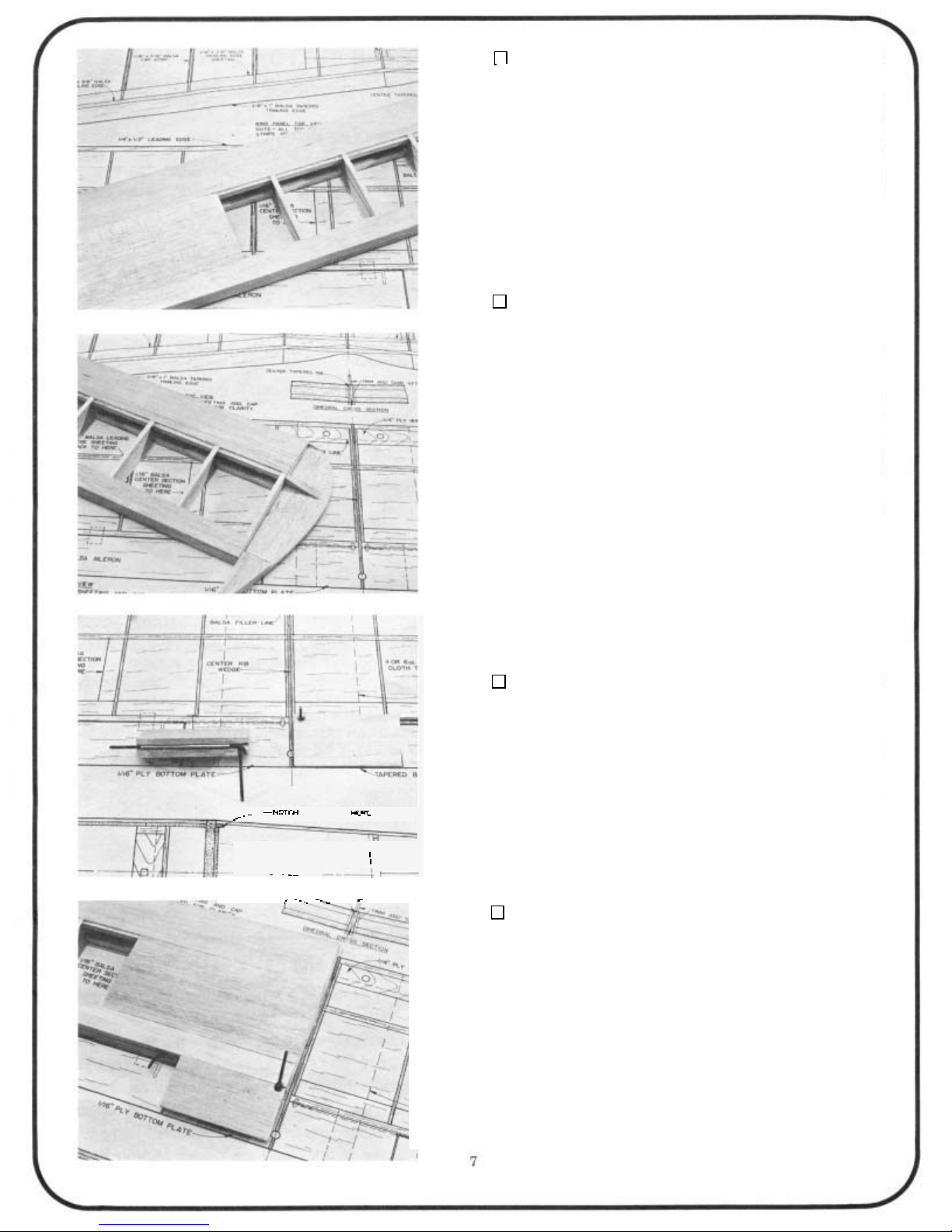
JOINING
GLUE THE CENTER RIB TO THE LEFT WING
PANEL
THE
BOTTOM
WING PANELS
With the wing panels
balsa center rib
sure the wider edge of the center rib is down and that the
leading edge and trailing edge are centered on the tapered rib.
5
Use
_
minute epoxy.
2.
it about
block
surfaces.
1/8"
so
that the center rib edges are flush with the wing sheeting
to
the root end of the left wing panel. Make
SAND THE CENTER RIB TO THE WING PANEL
CONTOUR
Rough cut the center rib to the wing airfoil, leaving
oversize. Sand the remainder away with a sanding
"up"
, glue the wedge-shaped
3.
ing and trailing edges of the panels.
make sure the leading edge of the wing is straight. Block up
the wing
slow set epoxy. See the drawing on the plan.
wing is upside down
the wing over and mark the aileron servo well location. Add the
1/16x2
I
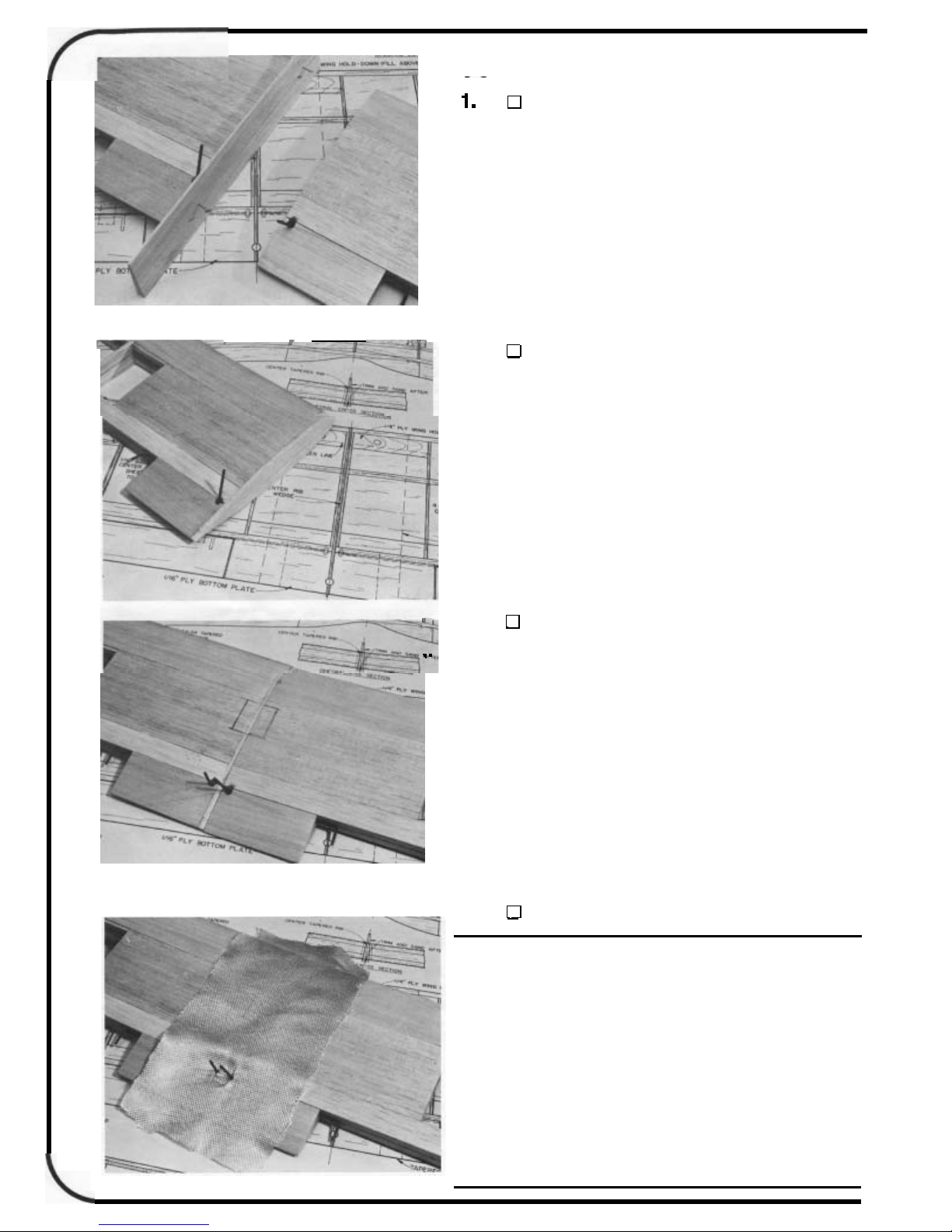
4.
JOINTHEWING PANELS; ADDTHEWING PLATES
Join the wing panels upside down. Line up the lead-
Use a straight edge to
7/8"
at the center and glue the panels together using
Remember the
at
this point! When the glue is dry, turn
x
3-1/4
DO
plywoodwing plateto the bottomof the wing.
GLASS THE CENTER SECTION OF THE WING
NOT OMIT
THIS
STEP!
Doingsomay result in a wing failure during flight!
Coat the
minuteepoxy and use
area
where the wings werejoined with
a
4
"
wide strip
of
6
oz.
5
glass or nylon
cloth to reinforce the center joint. Saturate the cloth with
off
epoxy and then wipe
should cover both the top and the bottom
When the epoxy is
any extra epoxy. The cloth strip
of
the wing joint.
dry,
sand the center section lightly
without sanding into the glass cloth.
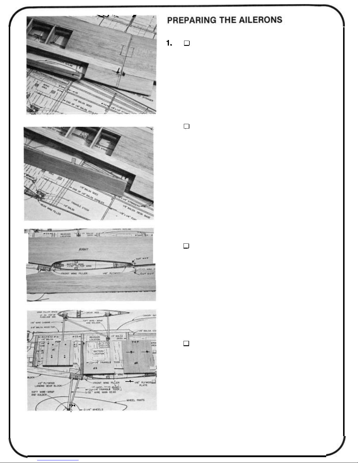
PREPARE THE AILERONS
Cut the aileron stock
length and draw a centerline down the leading edge of the
ailerons. Mark and drill the torque rod holes. Groove the aileron
for torque rod clearance. Make right and left ailerons.
2.
the wing trailing edge. Shape the leading edge
to a
the fit. Final sand the wing tips to match the aileron contour at
neutral. Do not permanently hinge the ailerons until after they
are covered.
CUTTHE HINGE SLOTS; FINAL SAND THE AILE-
RONS
Mark and cut the hinge slots into the ailerons and
“V’.
Temporarily install the ailerons with hinges to check
(5/8 x
17-1/2 tapered stock) to
of
the ailerons
LEFT
BUILDING
,
,
1.
“left”. Cut out part of the wing saddle area at the rear as shown
on the plan.
STOP!
the instructions on installationof 4
this instruction book.
2.
Firewall. Mark the “top” of the firewall (the bottom has a slight
angle). Mark the position of the motor mount. Mark and drillthe
holes for the motor mount
in positions in these holes you drilled. Temporarily place the
mount on the firewall with the screws. Cut the screws
,
back of the firewall
Notch a hole in Bulkhead # 2 for the throttle linkage. Prepare
Bulkhead #3 by drilling holes for the outer pushrod housings.
PREPARE THE FUSELAGE SIDES
Mark the inside of the fuselage sides “right” and
If
you plan to install a 4-cycle engine, read and follow
PREPARE THE BULKHEADS
Locate the 1/4
THE
so
FUSELAGE
-
cycle engines at the end of
x 3
x 2-3/4
4-40
they won’t get in the wayofthe fuel tank.
plywood Bulkhead
screws. Put the 4-40 blind nuts
#1,
off
the
in
9

3. D GLUE THE DOUBLERS TO
THE
FUSELAGE SIDES
Using Bulkhead #1 as a spacer, install the 1/8" balsa
doublers crossgrain on the inside of the fuselage sides. Cut the
doubler pieces from 1/8 x 3 x 36 balsa first, position and then
glue in place. Use slow set epoxy or thick cyanoacrylate. The
doubler should extend 1/4"beyond the position of bulkhead #3.
Trim the doublers to the fuselage contour.
Note:
Be careful
when
you
cut the
doubler
stock
as you
need
to use what is left in the next step.
4. D BUILD THE THREE REAR FORMERS
Make Formers #4,5 and 6 from 1/8 x 1/4 x 36 balsa.
Use the plans as a guide and cut the balsa to size. Glue the
parts together to make the three formers. Make push rod braces
from scrap 1/8 x 3 x 36 left over from the doubler stock in the
step you just did. The widths of the braces are the same as
that of each of the formers. The braces will be installed when
the pushrods are installed
later. STOP!
Did you read the 4-cycle
engine instructions if you plan to install a 4-cycle?
D MARK BULKHEAD POSITIONS
Mark the positions of bulkheads #2 and #3 on the
fuselage sides. Also
mark
the
position
of
the balsa dash between
#2 and #3. Mark the positions of the cabane blocks now if you
wish.
6. D DRILL PUSHROD EXIT HOLES
Mark and drill the holes in the fuselage sides for the
pushrod exits for the elevator and rudder. See the plans for
suggested positions of the pushrods to estimate the hole positions. A piece of brass tubing sharpened on the inside with an
X-Acto knife blade makes a neat, clean angled hole for tubestyle pushrods.
10
 Loading...