

Page 1
INSTRUCTION MANUAL
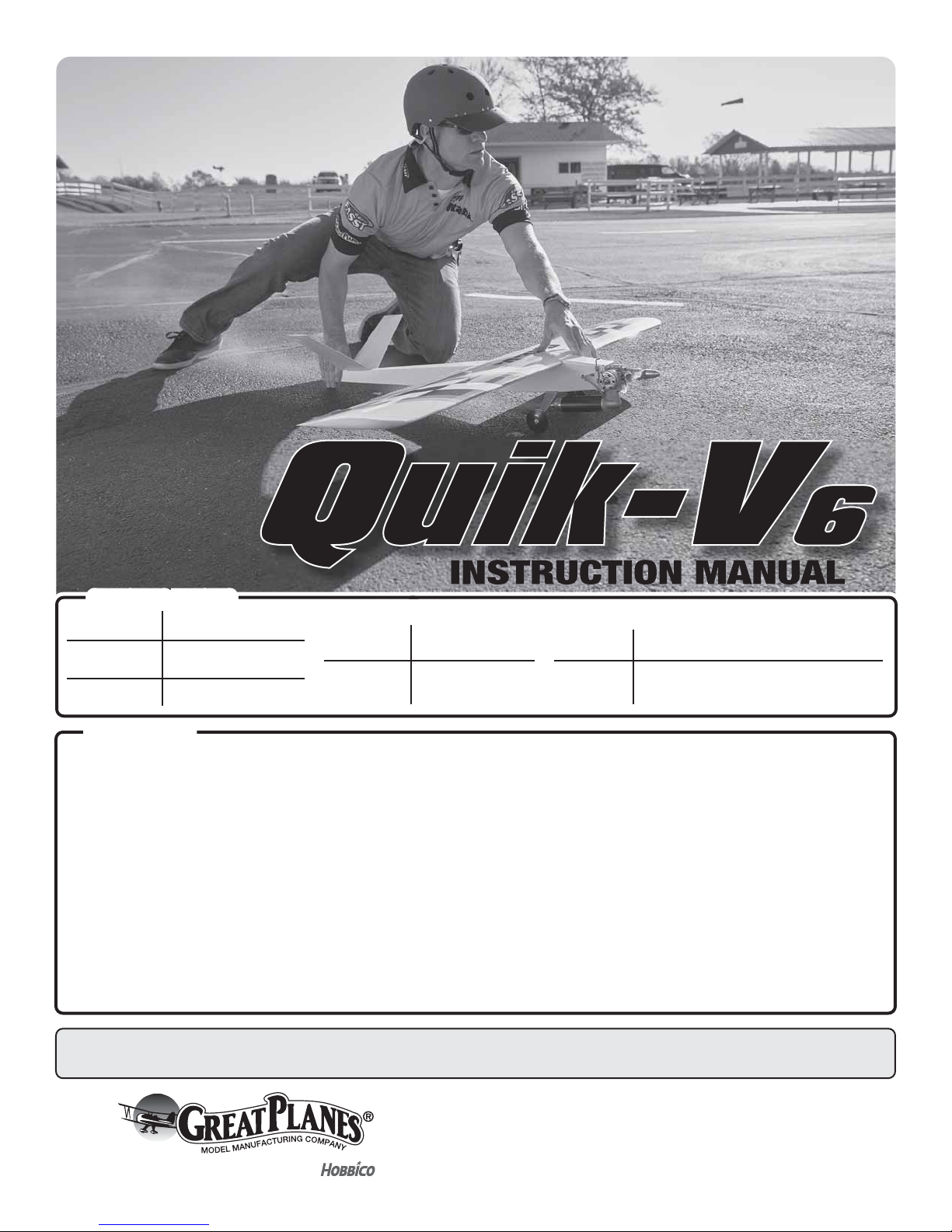
SPECIFICATIONS
Wingspan:
Length: 40.5 in [ 1030mm]
Wing Area: 503 in
WARRANTY
Great Planes® Model Manufacturing Co. guarantees this
kit to be free from defects in both material and workmanship at
the date of purchase. This warranty does not cover any
component parts damaged by use or modication. In no case
shall Great Planes’ liability exceed the original cost of
the purchased kit. Further, Great Planes reserves the right to
change or modify this warranty without notice.
In that Great Planes has no control over the nal assembly or
material used for nal assembly, no liability shall be assumed nor
accepted for any damage resulting from the use by the user of
the nal user-assembled product. By the act of using the
user-assembled product, the user accepts all resulting liability.
If the buyer is not prepared to accept the liability
associated with the use of this product, the buyer is
52 in [ 1320 mm]
2
[32.4 dm2]
Weight:
Wing
Loading:
3.6 – 3.75 lbs
[1630–1700 g]
16.5 – 17.2 oz /f t
[50– 52.5 g/dm2]
Radio: 4 −Channel with V-Tail Mixing
2
Engine: .40 − .55 cu in [6.5– 9.0 cc]
2-stroke glow
advised to return this kit immediately in new and
unused condition to the place of purchase.
To make a warranty claim send the defective part or item to
Hobby Services at the address below:
Hobby Services
3002 N. Apollo Dr. Suite 1
Champaign IL 61822 USA
Include a letter stating your name, return shipping address, as
much contact information as possible (daytime telephone
number, fax number, e-mail address), a detailed description of
the problem and a photocopy of the purchase receipt. Upon
receipt of the package the problem will be evaluated as quickly
as possible.
READ THROUGH THIS MANUAL BEFORE STARTING CONSTRUCTION. IT CONTAINS IMPORTANT
INSTRUCTIONS AND WARNINGS CONCERNING THE ASSEMBLY AND USE OF THIS MODEL.
© 2016 Great Planes Model Mfg. A subsidiary of Hobbico,® Inc.
Champaign, Illinois
(217) 398-8970, Ext 5
airsupport@greatplanes.com
GPMA1250
Page 2

TABLE OF CONTENTS
INTRODUCTION . . . . . . . . . . . . . . . . . . . . . . . . . . . . . . . . 2
SAFETY PRECAUTIONS . . . . . . . . . . . . . . . . . . . . . . . . . 2
ADDITIONAL ITEMS REQUIRED . . . . . . . . . . . . . . . . . . 3
Engine and Engine Accessories . . . . . . . . . . . . . . . . 3
Radio and Servos . . . . . . . . . . . . . . . . . . . . . . . . . . . . 3
Adhesives, Hardware, and Accessories . . . . . . . . . . 3
Glow Plug Ignitor . . . . . . . . . . . . . . . . . . . . . . . . . . . . 4
KIT INSPECTION . . . . . . . . . . . . . . . . . . . . . . . . . . . . . . . 4
ORDERING REPLACEMENT PARTS . . . . . . . . . . . . . . . 4
KIT CONTENTS. . . . . . . . . . . . . . . . . . . . . . . . . . . . . . . . . 4
ASSEMBLE THE MODEL . . . . . . . . . . . . . . . . . . . . . . . . . 5
Preparation . . . . . . . . . . . . . . . . . . . . . . . . . . . . . . . . . 5
Install the Ruddervator Servos . . . . . . . . . . . . . . . . . 8
Test Fit the V-Tail. . . . . . . . . . . . . . . . . . . . . . . . . . . . 10
Make the Carbon Fiber Pushrods . . . . . . . . . . . . . . 10
Make the Wire Pushrods . . . . . . . . . . . . . . . . . . . . . 13
Attach the V-Tail . . . . . . . . . . . . . . . . . . . . . . . . . . . . 14
Hinge the Ruddervators . . . . . . . . . . . . . . . . . . . . . . 16
Mount the Engine . . . . . . . . . . . . . . . . . . . . . . . . . . . 16
Hook Up the Throttle . . . . . . . . . . . . . . . . . . . . . . . . 17
Install the Fuel Tank . . . . . . . . . . . . . . . . . . . . . . . . . 18
Hook Up the Fuel Cut Wire . . . . . . . . . . . . . . . . . . . 20
Mount the Landing Gear . . . . . . . . . . . . . . . . . . . . . 22
Install the Fuel Tank . . . . . . . . . . . . . . . . . . . . . . . . . 23
Hook Up the Ailerons . . . . . . . . . . . . . . . . . . . . . . . . 25
FINAL ASSEMBLY . . . . . . . . . . . . . . . . . . . . . . . . . . . . . 26
Check the C.G. . . . . . . . . . . . . . . . . . . . . . . . . . . . . . 26
Attach the Tail Covers . . . . . . . . . . . . . . . . . . . . . . . 27
PREPARE THE MODEL FOR FLIGHT . . . . . . . . . . . . . . 30
Install the Battery and Receiver . . . . . . . . . . . . . . . 30
Final C.G. Check . . . . . . . . . . . . . . . . . . . . . . . . . . . . 31
Balance the Model Laterally . . . . . . . . . . . . . . . . . . 31
Set the Control Throws . . . . . . . . . . . . . . . . . . . . . . 32
Basic Checklist . . . . . . . . . . . . . . . . . . . . . . . . . . . . . 33
ENGINE SAFETY PRECAUTIONS . . . . . . . . . . . . . . . . . 33
AMA SAFETY CODE (excerpts) . . . . . . . . . . . . . . . . . . 34
QUIK-V6 TRIMMING NOTES . . . . . . . . . . . . . . . . . . . . . 34
QUIK-V SERIES HISTORY . . . . . . . . . . . . . . . . . . . . . . . 36
INTRODUCTION
Congratulations and thank you for purchasing the Great
Planes Quik-V6 Quickie 500 pylon racer. If you’re on a quest
for speed the Quik-V6 is the answer, but the Quik-V6s primary
objective is to be a competitive weapon in AMA 424 or 426
(Sport Quickie or Super Sport Quickie) pylon racing. If you
spend any time reviewing race results on the internet or if
you attend any of the major pylon races you’ll know that
Jim Allen is one of the premier pilots. Jim is the designer
of the Quik-V6 (as well as the Great Planes Proud Bird EF1
pylon racer). You can read all about Jim’s interesting and
insightful development history of the Quik-V6 (and the origin
of the name) on the back cover. Also make it a point to read
Jim’s regimen on i ght tr imming fo r pyl on rac ing o n pag e 34.
For the latest technical updates or manual corrections to
the Quik-V6 ARF visit the Great Planes web site at www.
greatplanes.com. Open the “Airplanes” link, then select the
Quik-V6. If there is new technical information or changes
to this model a “tech notice” box will appear in the upper
left corner of the page.
If you are not already a member of the AMA, please join! The
AMA is the governing body of model aviation and membership
provides liability insurance coverage, protects modelers’
rights and interests and is required to y at most R/C sites.
Academy of Model Aeronautics
5151 East Memorial Drive
Muncie, IN 47302-9252
Tele. (800) 435-9262
Fax (765) 741-0057
Or via the Internet at: http://www.modelaircraft.org
IMPORTANT!!! Two of the most important things you can
do to preserve the radio controlled aircraft hobby are to
avoid ying near full-scale aircraft and avoid ying near
or over groups of people.
SAFETY PRECAUTIONS
Protect Your Model, Yourself & Others…
Follow These Important Safety Precautions
1. Your Quik-V6 should not be considered a toy, but rather a
sophisticated, working model that functions very much like
a full-size airplane. Because of its performance capabilities,
the Quik-V6, if not assembled and operated correctly,
could possibl y cause injur y to yourself or spectators and
damage to property.
2. You must assemble the model according to the
instructions. Do not alter or modify the model, as
doing so may result in an unsafe or un yable model.
In a few cases the instructions may differ slightly from
the photos. In those instances the written instructions
should be considered as correct.
3. You must take time to build straight, true and strong.
4.
You must use an R/C radio system that is in good condition,
a correctly sized engine, and other components as
speci ed in this instruction manual. All components must
be correctly installed so that the model operates correctly
on the ground and in the air. You must check the operation
of the model and all components before every ight.
5.
If you are not an experienced pilot or have not own this
type of model before, we recommend that you get the
assistance of an experienced pilot in your R/C club for
2
Page 3
your rst ights. If you’re not a member of a club, your
TRANSMITTER
Futaba 4-channel on 2.4 GHz w/V-tail mixing
2S 1300mAh LiFe receiver battery
(HCAM6411)
FUTM4350
FUTM4190
(3) Futaba 9670SV
(FUTM0725)
(3) Futaba 9650
(FUTM0260)
(1) Futaba 3172SV
(FUTM0125)
(1) Futaba 3102
(FUTM0034)
R6303SB Micro
3-18ch (FUTL7661)
Futaba R617FS
FASST (FUTL7627)
(1) 6" dual servo
extension (FUTM4135)
(3) 6" (TACM2090)
RUDDERVATOR,
AILERON SERVOS
THROTTLE/
FUEL-CUT SERVO
RECEIVER
SERVO
EXTENSIONS
RECEIVER
BATTERY
ON-OFF SWITCH
SBC-1 CHANNEL
SETTING TOOL*
*Not required if using a Futaba transmitter with Serial Interface
S.Bus
Non-S.Bus
local hobby shop has information about clubs in your
area whose membership includes experienced pilots.
6. While this ARF has been ight-tested to exceed normal
use, if an engine larger than one in the recommended
range is used, the modeler is responsible for taking steps
to reinforce the high stress points and/or substituting
hardware more suitable for the increased stress.
We, as the ARF manufacturer, provide you with a top
quality, thoroughly tested ARF and instructions, but ultimately the quality and yability of your nished model
depends on how you assemble it; therefore, we cannot
in any way guarantee the performance of your completed
model, and no representations are expressed or implied
as to the performance or safety of your completed model.
REMEMBER: Take your tim e and fo llow t he inst r u c t ions
to end up w ith a w ell-bu i lt mod e l that i s straigh t and t r u e.
ADDITIONAL ITEMS REQUIRED
NOTE: Some of the items speci ed are in accordance
with current AMA/NMPRA rules. If you plan on racing your
Quik-V6, be certain to consult the rules for the latest speci ed
equipment to make sure your plane is in compliance.
Radio and Servos
Most of the specialty pylon racing items for AMA 426
(Super Sport Quickie), including the Jett brand engine and
muf er, J ett ba ck plate e ngine moun t, Jet t remote un iver s a l
needle valve, Tettra fuel tanks, Super Tanker fueler, etc.,
are available on the internet from Jett Engineering Inc.
and/or Darrol Cady Racing.
Engine and Engine Accessories
For sport flying:
❍ O.S. 46AXII ABL w/Muffler (OSMG0548) OR O.S.
.55AX ABL 2 w/muffler (OSMG0557)
For AMA 424 (Sport Quickie):
❍ ThunderTiger Pro .40 w/muffler
❍ APC 9 x 6 Sport propeller (APCQ9725)
For AMA 426 (Super Sport Quickie):
❍ Jett Engineering Inc. QJ-1 .40 engine and muffler
❍ Jett back plate mount
❍ Jett remote universal needle valve
❍ Darrol Cady or Sullivan thin-wall fuel tubing
(SULQ1205)
❍ Spare glow plugs (Merlin 1125A Red most
common)
❍ Jett Super Tanker syringe-type fueler
❍ Suitable propellers (APC 8.8 x 8.75 most popular –
APCQ8975)
❍ Bubbless, bladder-type fuel tank (Tettra 6 oz. or
Tettr a 5 . 25 oz.)
❍ Pylon racing-type glow igniter system
❍ Silver solder (STAR2000)
Adhesives, Hardware & Accessories
Other than common hobby tools here is a list of the rest
of the items required:
❍ Z-bend pliers (HCAR2000)
❍ 30-minute epoxy (GPMR6043)
❍ Dave Brown carbon ber tape (DAVR2000)
❍ Thin CA (GPMR6001)
❍ Medium CA (GPMR6007)
❍ CA applicator tips (HCAR3780)
❍ CA activator (GPMR6035)
❍ Threadlocker (GPMR6060)
❍ 1/4" RC foam rubber (HCAQ1000)
❍ 10-24 drill and tap set (or #25 or 5/32" drill and 10-
24 tap)
❍ Spare 10-24 x 1/2" nylon at-head screws (for main
landing gear)
❍ Covering iron (COVR2700)
❍ Cover Sock (COVR2702)
❍ Trim Sealing Iron (COVR2750)
❍ After-run engine oil (GPMP3001)
For optional carbon fiber ruddervator pushrods:
❍ (2) 4mm [5/32"] Midwest carbon ber pushrod
tubes (MIDR5721)
❍ (1) K&S 3/16" aluminum tube (K+SR8104)
On page 7 you’ll see the common practice of reinforcing all
the critical, high-stress joints with llets made from 30-minute
epoxy and chopped carbon ber or berglass. Dave Brown
carbon ber tape is recommended for this (DAVR2000).
3
Page 4
A covering iron is also required for applying the included
GPMA2550.....Backplate Engine Mount
GPMA2552.....Fuel Tank
GPMA4575.....Fuselage Set
GPMA4576.....Wing
GPMA4577.....Tail Surface Set
GPMA4578.....Landing Gear
GPMA4579.....Servo Hatch
GPMA4580.....Wheel Set
Mo noKote c ove ring over the wood tail c ove r s afte r they have
be e n glu e d into place, a s we ll as t ightening the covering ove r
the entire model in general. The 21st Century Sealing Iron
(COVR2700) and Cover Sock (COVR2702) are recommended.
A Trim Sealing Iron is also helpful (COVR2750).
Glow Plug Igniter
KIT INSPECTION
Before starting to build, inspect the parts to make sure
they are of acceptable quality. If any parts are missing or
are not of acceptable quality, or if you need assistance
with assembly, contact Product Support. When reporting
defective or missing parts, use the part names exactly as
they are written in the Kit Contents list.
If you’re a little serious about racing, a racing-type glow plug
igniter system is preferred over the one-piece, integrated
glow-driver/battery unit commonly used for sport ying.
Racing-type glow igniters developed for the ight line
feature a high-capacity battery and a lighted display
that can alert you of the condition of your glow plug and
automatically discontinue power after a prescribed time.
For security and safety, and to relieve stress from the
glow plug, the lightweight clip is connected to the battery/
controller unit via an electrical cord. Pylon racing glow
igniter systems are available from the aforementioned
pylon racing specialty sources.
NOTE: The stabilizer and wing incidences and engine thrust
angles have been factory-built into this model. However,
so me te chnic ally- minde d mod elers m ay wish to chec k the se
me a surem ents a nyway. To vi ew this informa tion visit the web
site at www.greatplanes.com and click on “Technical Data.”
Due to manufacturing tolerances which will have little or no
effect on the way your model will y, please expect slight
deviations between your model and the published values.
Great Planes Product Support
3002 N Apollo Drive, Suite 1
Champaign, IL 61822
Ph: (217) 398-8970, ext. 5
Fax: (217) 398-7721
E-mail: airsupport@greatplanes.com
ORDERING REPLACEMENT PARTS
Replacement parts for the Great Planes Quik-V6 ARF are
available using the order numbers in the Replacement
Parts List that follows. The fastest, most economical
service can be provided by your hobby dealer or mailorder company.
To locate a hobby dealer, visit the Great Planes web site at
www.greatplanes.com. Choose “Where to Buy”. Follow
the instructions provided on the page to locate a U.S.,
Canadian or International dealer.
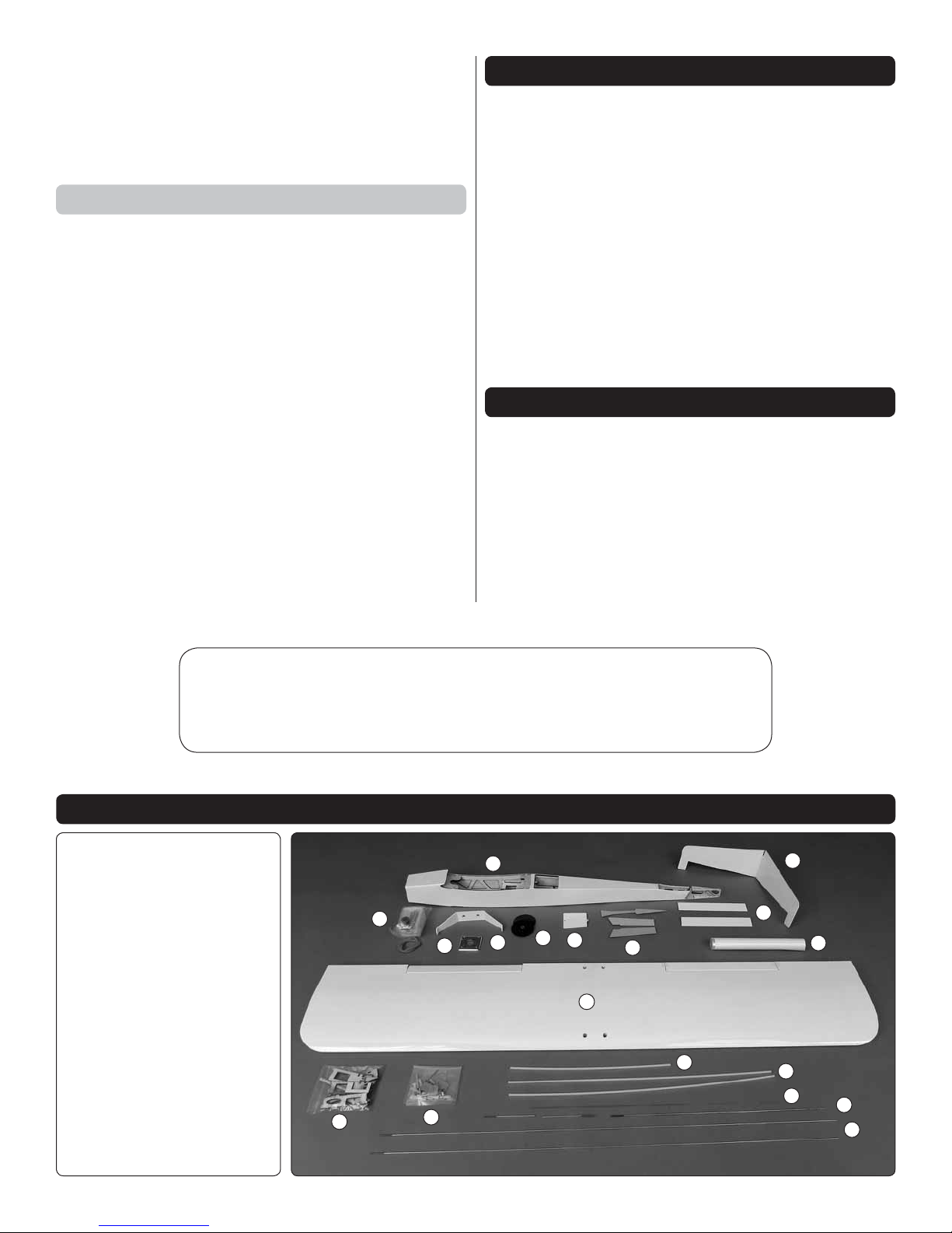
1. Fuse lage
2. V-Tail
3. Fuel Tank & Hardware
4. Engine Mount
5. Main Landing Gear
6. Main Wheels
7. Hatch Cover
8. Tail Covers
9. Ruddervators
10. MonoKote
11. Wing/Ailerons
12. Wood Parts
13. Hardware
14. Throttle Guide Tube
15. Ruddervator Guide Tubes
16. Fuel Cut Wire
17. Aileron/Throttle Pushrods
18. Ruddervator Pushrods
KIT CONTENTS
1
3
4
12
13
5
4
2
9
6
7
11
8
14
10
15
16
17
18
Page 5

ASSEMBLE THE MODEL
Preparation
1. Examine the covering over all the parts of the model
❏
to nd wrinkles or areas that are not bonded to the wood
underneath. Where necessary, use a covering iron with
a cover sock to tighten the covering, pushing down on
the iron to bond the covering to the wood. Be thorough—
this procedure can take anywhere from a few minutes to
an hour or so. The optimum temperature for shrinking/
bonding MonoKote is around 320°F – 360°F (which requires
a dial setting of about 350°F – 375°F on the 21st Century
Sealing Iron with a Cover Sock). If the covering bubbles or
blisters, this may indicate too much heat. Allow the area to
cool and don’t hold the iron in one spot for too long. Press
down harder and/or use less heat. A sharp hobby blade
may be used to puncture the bubble in a few areas, but be
careful; if using solution to apply vinyl graphics or trim cut
from MonoKote later, it will wick through the perforations
and cause the wood to swell, causing a minor blemish in
that area. You could always puncture these trouble spots
later after you have applied your graphics.
3. Then, laying the piece into position, gently squeegee
❏
out the solution with a piece of soft balsa. This procedure
removes air bubbles that would otherwise form between
the layers.
4. Allow to dry at least over night before permanently
❏
ironing the trim down—the longer you wait before ironing
the better.
2. When ready to apply graphics, trim colors may be
❏
cut from MonoKote. Applying MonoKote over MonoKote
is best done by spraying the back of the trim piece with
window cleaner. NOTE: If any of your trim graphics cross
the aileron hinge gaps it may be better to apply the graphics
after the hinges have been joined and the hinge gaps have
been sealed as illustrated on page 25.
5. There are several instances during assembly where
❏
epoxy cleanup with denatured alcohol will be necessary.
To conserve whole paper towels and to make cleanup
easier, stack a few paper towels on top of each other and
cut them into small squares as shown. This may seem
ridiculous now, but you’ll thank us later and continue to
keep a supply of paper towel squares on your workbench
from now on!
5
Page 6
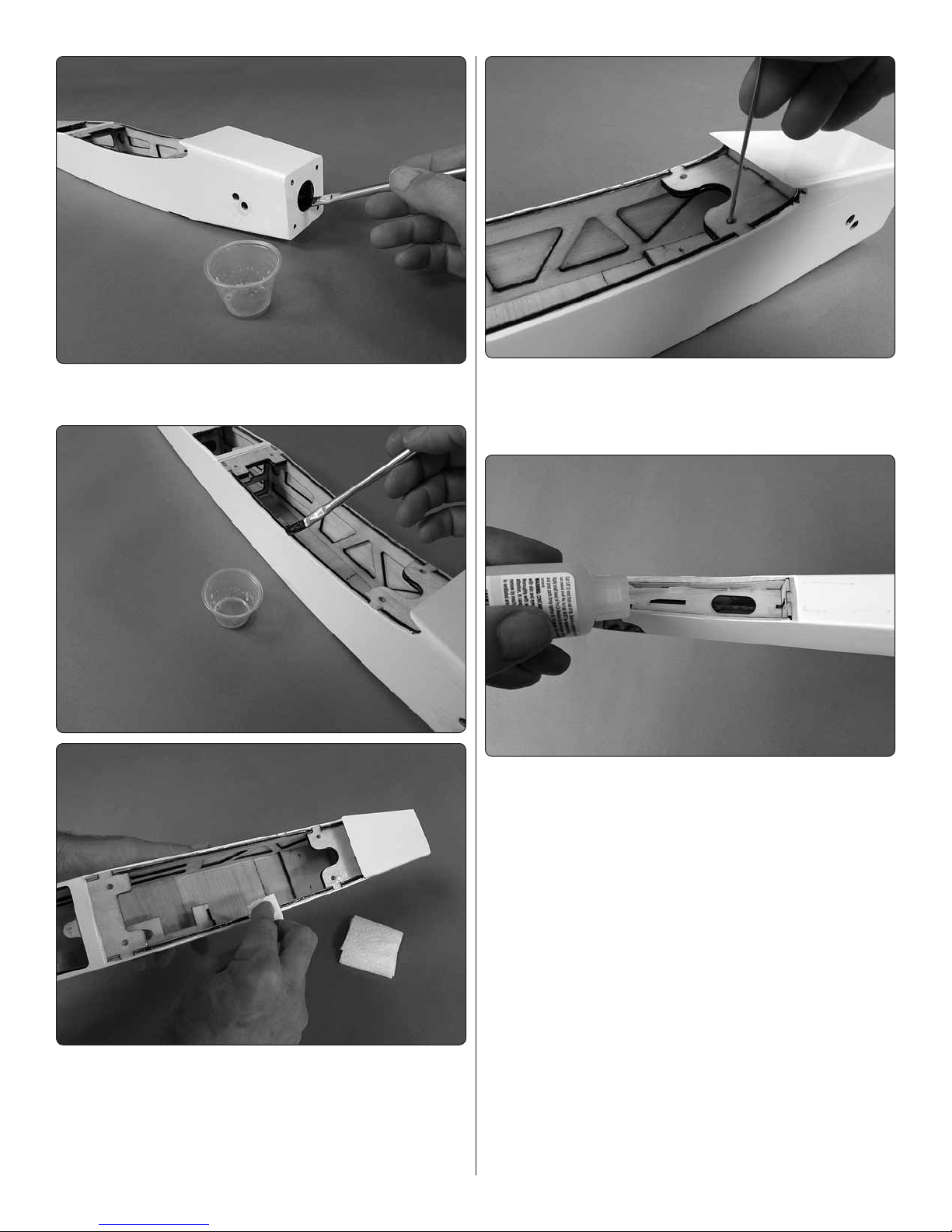
6. Use 30-minute epoxy to fuelproof areas that may be
❏
exposed to exhaust, fuel or cleaning solution (see next page).
8. Also lightly coat the holes in the wing bolt plates and
❏
the holes in the landing gear plate with 30-minute epoxy.
Allow to fully harden before re cutting the holes with a 1024 tap later.
9. Inspect all visible glue joints looking for areas in
❏
the cabin or tail that could use reinforcement. Where
necessary, use a CA applicator to apply thin or medium
CA to any glue joints that don’t look strong.
7. Don’t forget to coat the outside of the landing gear
❏
plate on the bottom of the fuselage. Apply liberally, allow
to soak in, and then remove excess epoxy before it
hardens.
Next, epoxy/carbon ber epoxy llets will be added to
key structural areas in the fuselage. First, we’ll mix up a
batch and apply to the landing gear plate and wing bolt
plates. Then, we’ll repeat the process for the rewall
with a new batch of resin. Separating the job into two
procedures insures plenty of working time before the
epoxy begins to harden.
6
Page 7
10. Use a toothpick to apply a little petroleum jelly to
❏
the threads in the blind nuts inside the rewall to prevent
excess epoxy from clogging up the threads. (Any material
that remains can also be removed with a 6-32 tap later.)
11. Chop 3" – 4" [80 – 100mm] of Dave Brown carbon
❏
ber tape into 1/8" [3mm] segments.
13. Apply the epoxy/carbon ber llets to the joints
❏
between the fuselage sides and the bottom of the wing
bolt plates and to the landing gear area as shown. You
can dip your nger in denatured alcohol to smooth and
form the llets as you go.
14. Mix up another batch of epoxy/carbon ber. Using
❏
the hole in the rewall for access, apply llets all the way
around the joint of the back of the rewall and the fuselage
sides and top and bottom—don’t worry too much about
getting excess epoxy into the blind nuts in the back of
the rewall—if necessary, a drill and 6-32 tap can be run
through the blind nuts to clean them out later.
12. Mix approximately 1 oz. [30cc] of 30-minute epoxy,
❏
then mix in the chopped carbon ber.
15. After all the epoxy has hardened, clean out the wing
❏
bolt holes and the landing gear bolt holes with 10-24 tap.
7
Page 8
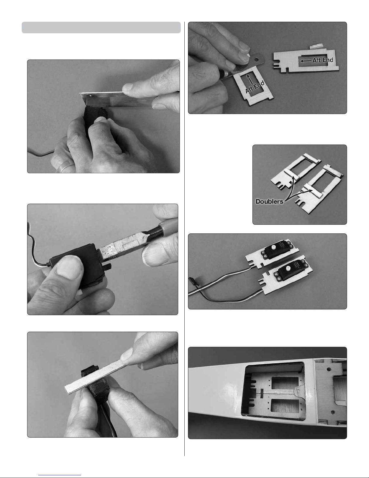
Install the Ruddervator Servos
1. If using the recommended servos that come with
❏
side tabs, carefully remove the tabs as follows:
A. First, use a razor saw to score or cut most of the
❏
way through the tabs—of course, use extreme care not
to cut into the servo wires where they exit the case!
2. If necessary, enlarge the openings in the servo trays
❏
to t your servos, then test- t the servos—if the cutouts
do require cutting, remove material from the aft end of the
openings.
3. Cut the included
❏
3mm lite-ply strip into
segments and glue
them to the bottom
of the servo trays for
screw doublers.
B. Then, break off the tabs with pliers.
❏
C. Use a stick with sandpaper to remove any
❏
remaining tab material and smooth the edges.
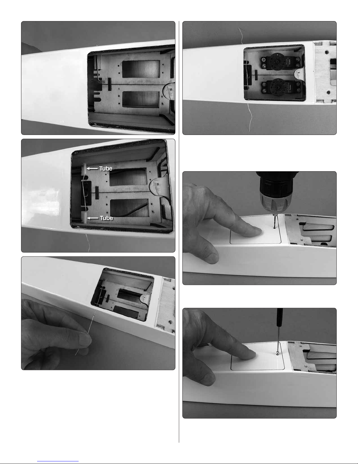
4. Drill 1/16" [1.6mm] holes for the servo mounting
❏
screws, temporarily mount the servos, remove the screws,
and add a few drops of thin CA to the screw holes. We’ll
remount the servos into the tray later.
5. Test- t, then securely glue the servo trays into the
❏
fuselage.
8
Page 9
7. Mount the servos. If using the included pushrod wires
❏
(whether as supplied, or with the carbon ber pushrod
tube option), enlarge the holes in the servo wheels with
a .074" drill.
8. Drill the hole for the servo hatch cover screw with a
❏
1/16" [1.6mm] drill.
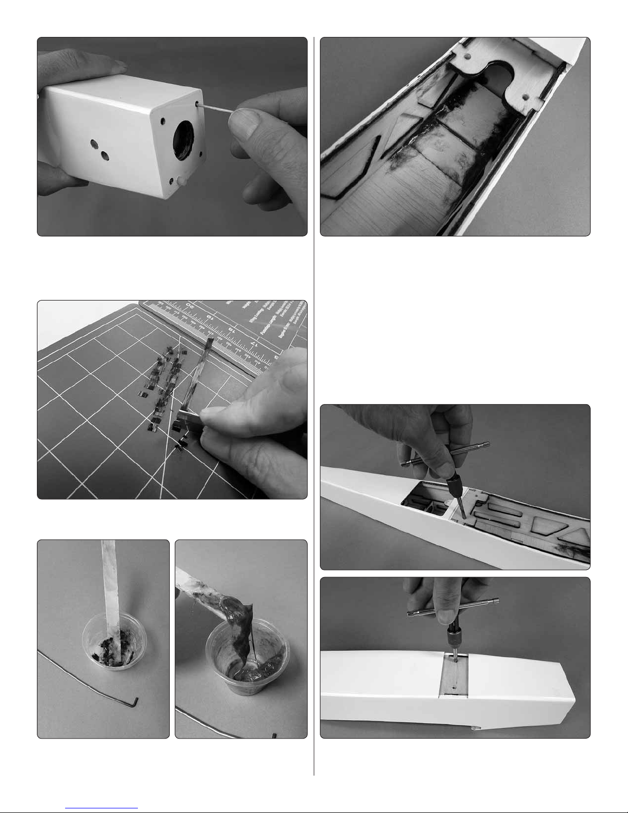
6. Determine how you are going to actuate the switch
❏
from outside the fuselage. One popular way is the “string
technique” to pull the switch on from one side and off
from the other. Test- t the switch and use a pin to locate
the holes for the string. Use a sharpened brass tube or a
drill to make holes in the fuselage for small plastic tubes
(cut from any kind of spray applicator) glued into position
as a bearing for the holes. Drill a hole in the switch for
the string, then mount the switch with threadlocker on the
threads and connect the string.
9. Fit the hatch cover with a #2 x 3/8" button-head
❏
screw. Remove the screw and hatch, add a few drops of
thin CA to harden the hole and allow to harden.
9
Page 10
Test Fit the V-Tail
Do not use any glue until instructed to do so—we’re going
to go as far as possible tting up the V-tail and hooking
up the pushrods before permanently gluing anything in.
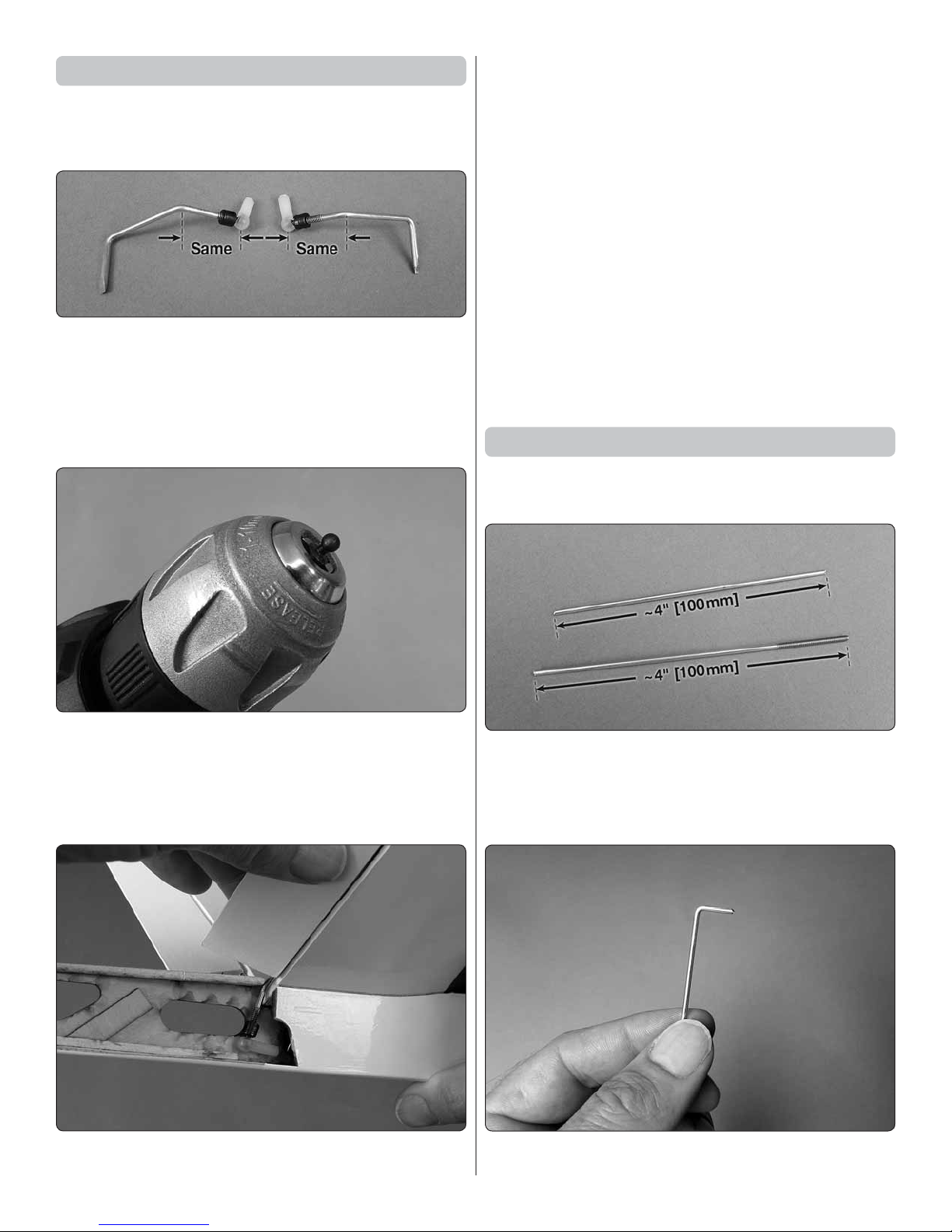
1. Temporarily thread the ball link balls onto the
❏
ruddervator torque rods. Examine the ball link balls to
make sure there is no burr or a sharp point on the tip. If
necessary, use a metal le to grind off the protrusion, then
snap the ball links onto the balls. Also make sure the ball
link balls are the same length. If necessary, shorten the
longer torque rod to match the short one.
notch in the former and the tab on the bottom into the
slot in the base). Without glue, test- t the ruddervators
with the hinges, torque rods and ball links. Make sure
the ruddervators move smoothly and the ball links don’t
interfere with anything. Make any adjustments necessary.
4. If you haven’t yet done so, program your radio for
❏
V-tail mixing.
Now it’s time to decide what kind of pushrods you are
going to use—either the included rod-and-tube setup,
or an optional 5/32" [4mm] carbon ber pushrods (not
included). Most pilots use the standard wire pushrods,
but some pylon racers prefer carbon ber pushrods for
ultimate precision.
If using the pushrods included, skip to Make the Wire
Pushrods on page 13. If using carbon ber pushrods,
follow these instructions, or use your preferred method to
make the pushrods:
Make the Carbon Fiber Pushrods
The instructions illustrate making one pushrod at a time,
but you could make them simultaneously.
2. Make sure the ball links can move freely and are not
❏
too tight. If they are too tight, chuck the base of the ball in
a hand drill (or, try another ball link if you have a supply of
your own). Polish the ball with metal polish and a cloth or
other mildly abrasive product until the ball links swivel on
the balls smoothly. Temporarily reassemble and set aside.
3. Temporarily t the V-tail to the fuselage (being certain
❏
to key the tab at the front of the V-tail center rib into the
1. Cut two, approximately 4" [100mm] segments from
❏
the threaded end of one of the long pushrod wires so you
have a threaded piece and a non-threaded piece. Clean
the wires with denatured alcohol, then roughen with
medium-grit sandpaper so glue will adhere.
2. Make a 90° “L-bend” as sharp as you can on one of
❏
the non-threaded wires.
10
Page 11
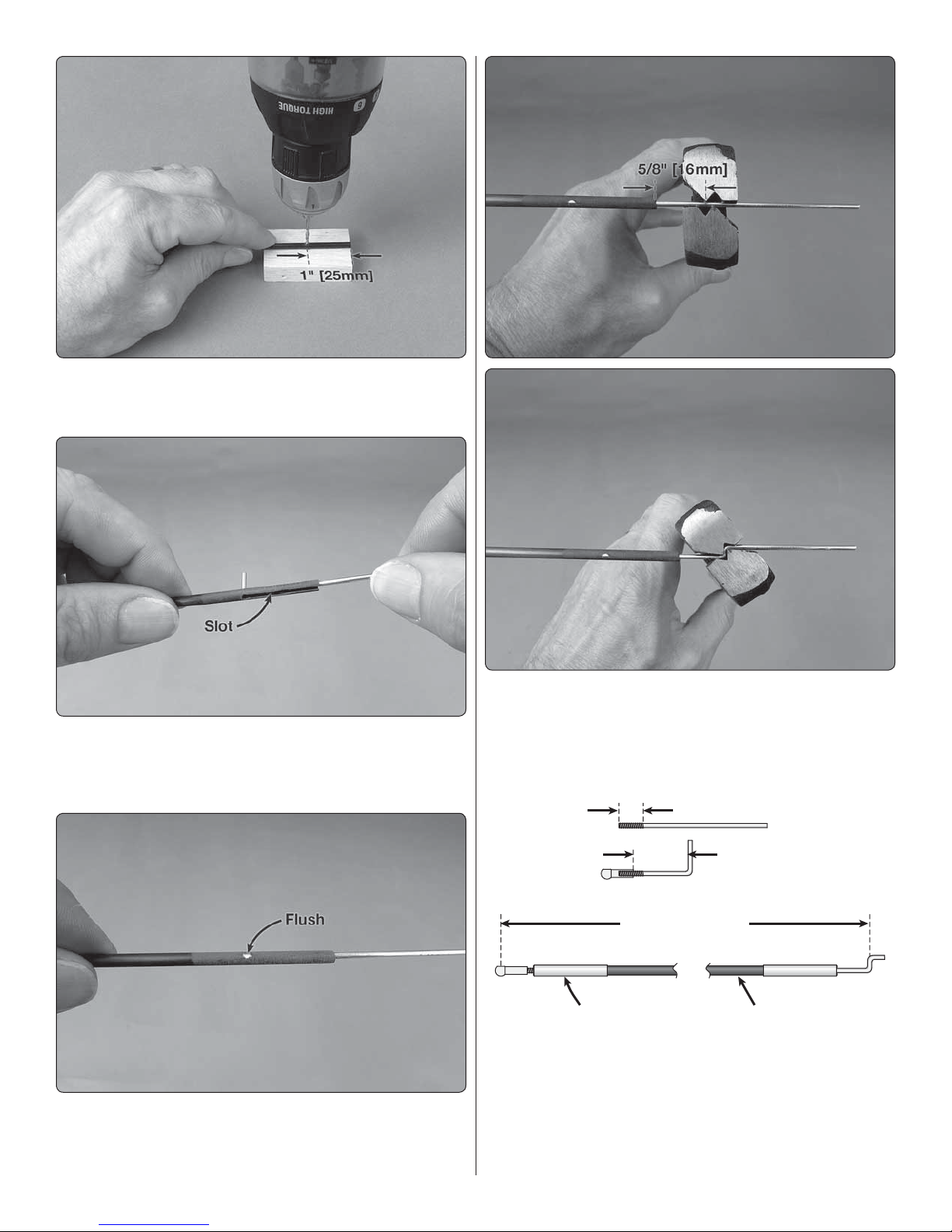
3. Drill a .074" or 5/64" [2.0mm] hole all the way through
16-5/8" [422mm]
Carbon Fiber TubeAluminum Tube/Sleeve
1/2" [13mm]
1-1/8" [29mm]
❏
a 5/32" [4mm] carbon ber pushrod tube 1" [25mm] from
the end.
4. Wearing respiratory and eye protection, use a razor
❏
saw or a reinforced cutoff wheel to cut a slot from one
of the holes up to the end of the tube, then install the
pushrod wire.
6. Make a Z-bend in the wire 5/8" [16mm] from the end
❏
of the tube. Cut the excess wire off the end of the Z-bend
and use a le or a reinforced cutoff wheel to deburr the
end of the wire.
5. Tack-glue the pushrod into place with a few drops of
❏
thin CA. Cut the “L” of the pushrod even with the tube, then
use a le to make the wire completely ush with the tube so
an aluminum sleeve can be t over the assembly later.
7. If installing the Futaba servos recommended, you
❏
can skip steps 8 through 12 and simply nish making the
pushrod to the dimensions shown above. If using other
servos, it would be better to custom- t the pushrods in
case the output shaft of your servos is different requiring
different pushrod lengths.
11
Page 12

8. Guide the pushrod up through the back of the
Aluminum Tube
Epoxy or CA
❏
fuselage and temporarily connect it to the servo.
11. Lay the pushrod wire alongside the pushrod tube
❏
with the socket in the ball link aligned with the mark you
made on the pushrod. (The pushrod was wrapped with
masking tape for clarity in the photo.) Mark the pushrod
1/8" [3mm] from the ball link and a third mark 1" [25mm]
from the second.
12. Cut the pushrod at the second mark made in the
❏
previous step. Then, drill the holes through the pushrod at
the second mark. Cut another slot same as was done on
the front of the pushrod.
13.
Unthread the ball link from the pushrod wire and use
❏
thin CA to tack-glue the pushrod into the tube and trim the
excess wire so it is ush with the outside of the tube.
14. Cut two 1-1/2" [40mm] pieces from a 3/16" K&S
❏
aluminum tube. Clean the inside of the tubes with a small
paper towel square and denatured alcohol.
9. With the V-tail and torque rods temporarily held
❏
in place and the ruddervator and elevator servo wheel
centered, mark the pushrod tube at the ball. This is where
the socket on the ball link must end up after the back of
the pushrod is done. Remove the pushrod.
10. Cut the threaded end of the 4" [100mm] pushrod
❏
wire so approximately 1/2" [13mm] of thread remains.
Thread a ball link most of the way onto the threads so
approximately 1/8" [3mm] of the thread is exposed, but
the ball link could be threaded on an additional 1/8" [3mm]
as well—this will leave room for adjustment later. Bend an
“L” bend in the wire 1-1/8" [29mm] from the ball link and
cut off the excess wire.
15. Thoroughly pack the slots in both ends of the
❏
pushrods with 30-minute epoxy mixed with microballoons
or milled glass ber and coat the ends of the pushrod tubes.
16. Apply epoxy inside the aluminum tubes, then slip
❏
the tubes over the ends of the pushrods (the aluminum
tube that goes over the pushrod with the Z-bend will have
to go on from the other end because it won’t t over the
12
Page 13

Z-bend). Be certain to remove any epoxy from the threads
on the pushrod wire. Allow the epoxy to harden.
17. If you haven’t yet done so, make and test- t
❏
the other pushrod the same way. After the epoxy has
hardened, thread the ball links onto the threaded end
of the pushrods. Set the pushrods aside until it’s time
to hinge the ruddervators. Skip to “Attach the V-tail” on
page 14.
Make the Wire Pushrods
5. With the V-tail held in position and the ruddervators
❏
and servo wheels centered, mark the pushrods where
they cross the holes in the servo wheels.
1. Cut the included pushrod guide tubes to a length
❏
of 14-1/2" [370mm] and the included pushrod wires to a
length of 17-1/2" [445mm]. Use medium-grit sandpaper to
roughen the outside of the guide tubes so glue will adhere,
then install the tubes up through the formers in the fuselage.
2. Thread a ball link ball about 3/8" [10mm] onto each
❏
of the pushrod wires.
3. Thoroughly clean the pushrod wires with a paper
❏
towel square and denatured alcohol. Lightly coat the
wires with any light oil.
6. Disconnect the ball links from the metal balls. Cut
❏
the pushrods 5/16" [8mm] past the marks, chamfer ends
of the wires to remove any burrs, and then make a Z-bend
in each pushrod wire at the marks.
4. Install the pushrods up through the guide tubes.
❏
Place the V-tail with the torque rods and ball link balls into
position and snap the ball links onto the balls.
7. Connect the pushrods to the servos.
❏
13
Page 14

8. Glue the guide tubes into the two formers in the
MarkMark
11"
[280mm]
11"
[280mm]
❏
fuselage with medium CA and a CA applicator tip.
Attach the V-Tail
1. If you haven’t yet done so, permanently attach the
❏
thread-on ball link balls to the ruddervator torque rods
with threadlocker, epoxy, JB Weld or even silver solder if
you prefer.
2. Use medium-grit sandpaper to roughen the torque
❏
arm portion of the torque rods that go into the ruddervators
so glue will adhere.
5. If any covering does require trimming, use the tip of
❏
a soldering iron set to about 400°F to melt through the
covering where necessary.
6. Also trim off any MonoKote that may have been
❏
wrapped around the stab saddle.
3. Securely glue the torque rods into the ruddervators
❏
with 30-minute epoxy. Set aside and allow the epoxy to
harden.
4. Hold the V-tail into position on the fuselage and view
❏
the joint from the bottom. Make sure the covering has
been trimmed so there will be a full, wood-to-wood glue
joint between the bottom of the V-tail and the fuselage. If
necessary, use a ne-point felt-tip pen to mark where the
fuselage sides meet the bottom of the V-tail halves.
7. Without using any glue, t the ailerons to the wing
❏
with the hinges and tape the ailerons to the wing so they
will be centered. Use a ne-point felt-tip pen to mark
centerline of wing between aft wing bolts. Also mark lines
on each aileron 11" [280mm] out from centerline.
14
Page 15

8. Mount the wing to the fuselage with the included
❏
10-24 wing bolts.
NOTE: In following images you will see the
ruddervators connected to the V-tail, but yours should
not yet be installed (or at least not yet permanently
attached with the hinges).
edge of the ailerons. If the tips do not align, carefully sand
the high-side of the stab saddle until you can get the V-tail
to align—use care—sanding a small amount of material
can have a drastic effect. (The stab in the image needs to
be rotated clockwise to bring the left tip up and the right
tip down, requiring material to be trimmed from the right
fuselage side at the stab saddle.)
9. Fit the V-tail to the fuselage. Place a weight on the
❏
V-tail to hold it down. View the assembly from 4' – 6' [1 – 2m]
behind the plane.
10. When viewing the model from behind, the tips of the
❏
V-tail should align with the marks precisely at the trailing
11. Once alignment has been achieved, prepare to
❏
permanently glue on the V-tail. Mix about 1/4 oz. [10cc] of
30-minute epoxy. First apply a lm of epoxy to all joining
surfaces, then add microballoons to what remains in the
cup and repeat the process coating all joining surfaces
with the epoxy/microballoons mixture.
12. Fit the V-tail into position, place weight over the
❏
V-tail to hold it down and double-check the alignment.
Wipe away excess epoxy and do not disturb the assembly
until the epoxy has hardened.
15
Page 16

Hinge the Ruddervators
1. Install the ruddervator pushrods if they aren’t already
❏
installed. Connect the balls on the ruddervator torque rods
to the ball links on the pushrods, then t the ruddervators
to the V-tail with the hinges—be certain the hinges remain
centered as they go in.
Mount the Engine
Installation of both a sport setup with an O.S. Max .55AX
with the included back plate mount and the Jett QJ-1
engine for AMA 426 with the Jett back plate mount are
illustrated. Follow the instructions for the setup you will
be using.
SPORT ENGINE WITH INCLUDED BACKPLATE MOUNT:
2. Connect the ruddervator servos to your receiver and a
❏
battery so you can operate the servos and ruddervators with
your transmitter. Make sure everything moves smoothly and
operates correctly and that the pushrods are the correct
length so the ruddervators will be centered when the servos
are centered. Make any adjustments necessary.
3. Permanently join the ruddervators with the torque
❏
rods to the V-tail by securely gluing in the hinges with 6
– 8 drops of thin CA on both sides of each hinge. Allow
time between drops so the CA soaks into the hinge slots
instead of running down the hinge gap.
1. If using the O.S. .46 or .55AX (or most other engines
❏
that will have the carburetor arm on the bottom with the
engine mounted on its side), cut the back plate template
labeled “Back” from the back of the manual. Tape the
template to the back of the back plate mount, then mark
the throttle pushrod hole using a small drill. (This hole also
aligns with the hole for the throttle cut wire in the Jett
Engineering back plate mount.)
4. Any excess CA or CA “fog” can be removed with a
❏
small paper towel square and debonder.
5. Pull hard on each ruddervator to make sure the
❏
hinges are secure.
The wood tail covers will be added after it has been
determined whether or not any ballast is required in
the tail to achieve the correct C.G.
2. Drill a 1/16" [1.6mm] hole at the mark, then enlarge
❏
the hole with a 3/16" [4.8mm] drill.
3. Run a 6-32 tap down through the blind nuts in the
❏
rewall to clean up any epoxy leftover from the llet inside.
If the tap won’t go through, drill out the obstruction with a
#36 (or 7/64" [2.8mm]) drill, then run the tap.
16
Page 17

4. Temporarily fasten the back plate mount to the
❏
rewall as shown with four 6-32 x 5/8" [16mm] SCHS
(socket-head cap screws). Use the hole in the mount as
a guide to drill an 11/64" [4.4mm] (or 3/16" [4.8mm]) hole
through the rewall. Remove the mount.
Hook Up the Throttle
1. Glue the laser-cut 1/8" [3.2mm] plywood doubler
❏
to the bottom of the laser-cut 1/8" [3.2mm] plywood
throttle servo mount. Test- t your servos and make any
adjustments if necessary.
5. M3 x 10 SHCS and M2.5 x 10 SHCS are included for
❏
mounting your engine to the included back plate mount.
These screws should be slightly longer than the screws that
are in your engine. Remove the back plate from your engine
and fasten the back plate mount with whichever screws are
suitable and a drop of threadlocker on the screws.
2. Glue the throttle servo mount and the laser-cut 1/8"
❏
[3.2mm] plywood support for the front of the mount into
the fuselage.
6. Mount the back plate mount to the rewall with four
❏
6-32 x 5/8" [16mm] SCHS and threadlocker.
Mount the landing gear as illustrated on pages 22 & 23.
Refer to these images to hook up the throttle as described
in the following steps.
17
Page 18

3. Cut the 3/16" [4.8mm] throttle guide tube
Screw-Lock Connector
4-40 Set Screw
One-Way Star Retainer
❏
approximately one inch longer than required (for trimming
later). Roughen the tube with medium-grit sandpaper so
glue will adhere, then install the tube through the back
plate mount and the rewall. Glue the front of the guide
tube into the back of the rewall.
4. Mount the throttle servo to the servo tray. Cut the
❏
guide tube to the correct length, then install the throttle
pushrod using a clevis and a silicone retainer on the
carburetor arm and a screw-lock connector with a metal
one-way star retainer on the servo arm. Glue the guide
tube to the side of the fuselage and glue the laser-cut 1/8"
[3.2mm] guide tube holder into position.
3. Use tape to wrap the sides and bottom of the tank in
❏
a sheet of 2-1/2" x 5" [60 x 130mm] 1/4" [6.5mm] RC foam.
5. Use the radio to set up your throttle linkage and lock
❏
the pushrod to the screw-lock connector with the 4-40 set
screw and threadlocker.
6. Mount the muf er to the engine.
❏
Install the Fuel Tank
4. Install the fuel tank and hold it into position with the
❏
1/8" [3.2mm] lite-ply fuel tank plate and another piece of
1/4" [6.5mm] RC foam.
1. Prepare the fuel tank as shown—it would be a good
❏
idea to mark the location of the fueling line (“F”) and the
vent/pressure line (“V”) on the outside of the tank so you
don’t forget when connecting the fuel tubing later.
2. Insert the stopper into the tank and tighten the screw
❏
to expand the stopper sealing the tank.
5. Guide the pressure/vent line and the pickup fuel
❏
lines through the holes in the side of the fuselage and
connect them to the fuel tank. Connect the pickup tube
to the carburetor and the pressure/vent line to the muf er.
Skip to Hook up the Ailerons on page 25.
18
Page 19

JETT QJ-1 ENGINE
The fuel line included with this kit is suitable for the fuel
lines from the fuel tank to the needle valve and from the
fuel tank to the muf er, but thin-wall fuel tubing from
Darrol Cady or Sullivan is preferred for the line from the
needle valve to the engine because it will be easier for the
fuel cut wire to pinch for stopping the engine.
1. Form the fuel cut wire before mounting the engine:
❏
NOTE: Forming the loop on the fuel cut wire is somewhat
of an art that takes a little practice—if your rst attempt
at making the loop is unsuccessful using the wire that
comes with this kit, make a new wire from K&S .031"
music wire. The method illustrated below uses a 3/16"
[4.8mm] brass tube for making the loop, but round-nose
pliers could also be used to make the loop.
A.
Use 400-grit sandpaper to scuff 2" – 3" [50 – 75mm] of
❏
one end of the wire and clean off any residue or oxidation.
E. Use silver solder to permanently close the
❏
loop. Use steel wool to thoroughly clean any residual
soldering ux from the wire, then apply a ne coat of oil
so the wire won’t rust. Set the fuel cut wire aside.
2. Run a 6-32 tap down through the blind nuts in the
❏
rewall to clean up any epoxy leftover from the llet inside.
If the tap won’t go through, drill out the obstruction with a
#36 (or 7/64" [2.8mm]) drill, then run the tap.
B. Wrap the cleaned end of the wire four or ve times
❏
around a 3/16" [4.8mm] tube or rod—the coils will get
tighter with each wrap until the I.D. of the last coil is
about the same as the tube.
C. Cut off the extra coils so only the last, tightest coil
❏
remains.
3. Temporarily fasten the back plate mount to the
❏
rewall as shown with four 6-32 x 5/8" [16mm] SHCS.
Hook Up the Fuel Cut Wire
D. Use pliers to bend and manipulate the coil until it
❏
will slip through the hole in the back plate mount and
your fuel tubing will pass through.
1. Mark the center of the hole in the back plate mount
❏
onto the rewall for the guide tube for the fuel cut wire.
Drill a 1/16" [1.6mm] pilot hole through the rewall at the
mark, then enlarge the hole with a 1/8" [3.2mm] drill.
19
Page 20

3. Remove the engine mount from the rewall. Use a
❏
hobby knife and/or a small, at-blade screwdriver to pick
the material out of the counter bore. Use your covering
iron to make sure the covering is thoroughly sealed to the
rewall around the hole.
4. Cut the 1/8" [3.2mm] guide tube for the fuel cut wire
❏
to a length of 11" [280mm]. Roughen the tube so glue will
adhere, then insert the tube into the rewall so the end of
the tube aligns with the bottom of the counter bore hole.
Use thin CA to glue the tube into the hole from the backside of the rewall.
5. Using care not to get any glue inside the tube,
❏
fuelproof the bare wood inside the hole with CA or epoxy.
2. The hole in the rewall for fuel cut wire must be
❏
counter-bored so the loop can travel far enough to pinch
the fuel line without overdriving the servo. The easiest
way to cut a precise counter-bore is with a 1/4" K&S brass
tube sharpened on the end. Mark a line on the tube 3/8"
[10mm] from the end and use a drill to turn the tube into
the rewall up to the line. This will provide a counter bore
that’s approximately 3/16" [5mm] deep.
6. Install one of the 6-32 x 5/8" [16mm] SHCS into the
❏
hole in the back plate mount near the engine exhaust,
then mount the back plate mount to your engine.
7. Mount the engine to the rewall with four 6-32 x 5/8"
❏
[16mm] SHCS and threadlocker.
Refer to this photo for the following three steps.
20
Page 21

8. Position the remote needle valve mount where
❏
desired so that the mounting screws will thread into the
side of the rewall (also making sure they will not interfere
with the engine mount screws already in place). Drill 3/32"
[2.4mm] holes for one of the screws and temporarily
mount the needle valve with two #4 x 1/2" [13mm] screws.
9. Remove the screws, harden the holes with thin CA,
❏
allow to harden, then mount the needle valve.
11. Glue the fuel-cut servo mount and the laser-cut 1/8"
❏
[3.2mm] plywood support for the front of the mount into
the fuselage.
10. Glue the laser-cut 1/8" [3.2mm] plywood doubler to
❏
the bottom of the laser-cut 1/8" [3.2mm] plywood fuel-cut
servo mount. Test- t your throttle servo and make any
necessary adjustments.
Refer to these images to hook up the fuel-cut wire as
described in the following steps.
21
Page 22

Screw-Lock Connector
4-40 Set Screw
One-Way Star Retainer
12. Mount the fuel-cut servo to the servo tray with a
6-32 Flat Head Screw
6-32 Set Screw
Bushing
❏
servo arm cut down to the correct length. Cut the guide
tube so it won’t interfere with the throttle servo arm when
the arm rotates all the way forward, then install the fuel
cut wire with a screw-lock connector with a metal oneway star retainer on the servo arm.
13. Glue the guide tube to the side of the fuselage and
❏
glue the laser-cut 1/8" [3.2mm] guide tube holder into
position. Balsa scraps (not included) can be used to help
secure the guide tube to the side of the fuselage so it
won’t become dislodged or interfere with the fuel tank.
rst. This takes a lot of elbow grease, but that’s the way it’s
done! Use whatever means available to grind the edges
such as a belt sander, a grinding wheel or a metal le.
Finish with increasingly ner grades of wet-dry sandpaper
until the gear is polished to suit your taste. Steel wool and
dish soap (or a Brillo pad) really make it shine!
14.
Route the fuel line from the engine to the needle valve
❏
through the loop in the fuel cut wire and use the radio to set
the servo travel and nalize your fuel cut linkage—Darrol
Cady or Sullivan 3/32" fuel line is preferred for this segment
of the fuel system. Lock the fuel-cut wire to the screw-lock
connector with a 4-40 set screw and threadlocker.
Mount the Landing Gear
The main landing gear is fastened to the fuselage with
the supplied 10-24 x 1/2" [13mm] nylon at-head screws.
This is a “break-away” system where the bolts will break
allowing the gear to separate from the plane to prevent
structural damage in the event of an unusually hard
landing. It is a good idea to purchase spare screws from
your local hardware or home improvement store and store
them in your eld box when you go to the races.
1. The landing gear may be used as-is, but most pilots
❏
prefer to chamfer the front and back edges of the gear
2. Mount the wheels to the landing gear as shown—
❏
be certain to lightly wet the threads of the screws with
threadlocker.
22
Page 23

5/16"
[8mm]
10-24 x 5/8" Nylon
Landing Gear Screw
3. Cut the included 10-24 x 5/8" [16mm] nylon landing
V-Cut
3/32" [2.4mm]
“cross hole”
2-1/2"
[60mm]
❏
gear screws to a length of 5/16" [8mm].
4. Mount the landing gear to the fuselage with the
❏
screws—note that the gear may be swept forward for
landing and taking off from grass or swept back for hard
surfaces.
5. Check the screws inside the fuselage—make sure
❏
you’ve cut them so they are not protruding from the
landing gear plate too far to interfere with the fuel tank.
Trim farther if needed.
1. Prepare and t the aluminum fuel tube and silicone
❏
pickup line as illustrated.After making the "V" cut, also
use a 3/32" sharpened brass tube to cut a "cross hole"
throught both sides of the tubing.
2. Secure the stopper in the tank with the hardware
❏
included with the tank – don’t forget the thin, metal plate
shown in the instructions that came with the Tettra tank.
Install the Fuel Tank
A Tettra 6 oz. bubbles fuel tank is illustrated. There is
more than one way to prepare the tank, but the method
illustrated is popular. Because the tank features a
collapsing bladder (pressurized between itself and the
plastic container) only a single pickup line is used inside
the tank. A Bubble Jett Fuel Tanker syringe-type fueler
(or similar) is required for lling the tank properly without
introducing air into the tank.
3. If the fuel tank ever requires removal in the future, it
❏
will be helpful to have a strap made from tape as shown
to facilitate pulling the tank out.
23
Page 24

4. The fuel tank must be stabilized so it cannot shift
❏
forward or aft, but because the tank is bubble-less,
completely isolating the tank in RC foam is not necessary.
But some foam will be helpful for holding the tank into
place and preventing vibration from eventually wearing
the tank. A popular method for keeping the tank from
moving forward is a popsicle stick or similar wood plate
fastened to the tank with Zap Goo and/or tape. Sheets of
1/4" [6.5mm] RC foam were also held to the sides of the
tank with tape.
6. Use additional pieces of foam padding on top of
❏
the tank and under the tank as needed. As shown, the
tank was secure and will not shift forward or aft, but if a
little more security is desired a balsa stick could be glued
across the fuselage sides at the back of the tank.
7. Mount the muf er and connect the fuel lines. Might
❏
as well install the propeller too—be certain to lock the
propeller down so that it will be horizontal when the
piston is at the top of the compression stroke to prevent
damaging the tips when landing.
5. Guide the fuel lines through the holes in the side of
❏
the fuselage and connect them to the fuel tank. Install
the tank as you guide the lines through – be certain the
fuel lines are not kinked or pinched inside the fuselage. If
you have any concerns about the fuel lines being kinked
inside the fuselage, you could always pull the engine and
view the lines through the hole in the rewall.
NOTE: If you ever replace the wing bolts with different
bolts, be certain they do not contact the top of the
fuel tank.
Hook Up the Ailerons
Note: The aileron servo is shown with the output shaft
toward the back of the wing. This orientation may be
necessary to clear the included fuel tank for the sport
setup, but if using a Tettra fuel tank the servo may be
positioned with the output shaft closer to the front of
the wing. In any case, test- t the wing with your servo to
make sure it clears your fuel tank before deciding which
way to mount the servo.
24
Page 25

1. The ailerons should already be test- tted to the
❏
wings from the V-tail alignment procedure. If you haven’t
yet done so, make sure the ailerons t properly to the
wing and torque rods and make sure the ailerons move
up and down freely. Make any adjustments necessary.
2. Remove the ailerons. Apply 30-minute epoxy to the
❏
joiner wires where they go into the ailerons and in the
joiner pockets in the ailerons. Join the ailerons to the wing
with the hinges and remove excess epoxy that comes out
of the ailerons. Apply 6 – 8 drops of thin CA to both sides
of all the hinges.
5. Examine the hinge gaps on the top and bottom of
❏
both ailerons. Larger blobs of CA can be picked away with
a hobby knife while smaller smears can be removed with
a small paper towel square dampened with CA debonder.
3. After the CA on the hinges has hardened, pull hard
❏
on each aileron to make sure the hinges are secure.
In the following steps the aileron hinge gaps will be
sealed from the ends of the torque rods out to the tips.
This is an important procedure to prevent utter and
increase the effectiveness of the ailerons.
4. Cut four 1/2" x 8-3/4" [10mm x 220mm] strips from
❏
the included white MonoKote sheet.
6. Use a couple strips of tape to hold one of the ailerons
❏
as up as far as it will go.
25
Page 26

7. Lay one of the strips of MonoKote on the bottom
13/16"
[20mm]
Swivel
❏
of the wing with the edge extending forward of the hinge
gap by approximately 1/8" [3mm]. Use a regular covering
iron to iron the piece of covering to the wing only.
10. Trim any excess covering as necessary, or simply
❏
iron it down to the bottom of the aileron.
11. Remove the tape that was holding the aileron
❏
down, then move the aileron up and down a few times
to make sure it moves reasonably smoothly. Make any
adjustments necessary.
12. Seal the top of the aileron and the top and bottom
❏
of the other aileron the same way.
13. Any glue or residual MonoKote adhesive that may
❏
have been deposited on the strips may be cleaned with a
small paper towel square and CA debonder.
8. Use a trim iron to seal the covering tightly all the way
❏
down the trailing edge of the wing only.
9. Now seal the strip down the leading edge of the aileron.
❏
14. Use a 3/8" [9.5mm] brass tube sharpened on the
❏
end or a hobby knife to cut a hole in the wing sheeting and
through the foam to pass the aileron servo wire. Install
the aileron servo. Drill 1/16" [1.6mm] holes for the servo
mounting screws and mount the servo with the screws.
Remove the screws, add a few drops of thin CA to the
screw holes and allow the CA to harden.
26
Page 27

the ends of the wires. Enlarge the holes in the servo wheels
3"
[76mm]
with a .074" [1.9mm] drill, then connect the pushrods.
18. Use your radio to center the servo and the ailerons
❏
adjusting the length of the pushrods as necessary. Install
silicone retainers on the clevises and the servo screw in
the servo wheel.
FINAL ASSEMBLY
Check the C.G.
15. Thread a nylon swivel onto each torque rod until it
❏
is 13/16" [20mm] from the bottom of the wing—grasping
the swivels with a paper towel square or a tissue makes
them easier to turn.
16. Mount the aileron servo in the wing. Make the aileron
❏
pushrods as shown and attach them to the swivels. With
the servos and the ailerons centered, mark the pushrods
where they cross the servo wheels. Note: High-wing
Quickie 500 planes do not require aileron differential, but
the pushrod hardware and torque rod con guration on
some quickies require offsetting the pushrods forward of
the pivot point in the servo wheel to remove the “backward”
differential (more down than up) that results. But since the
swivel clevises used on the Quik-V6 align the pivot point
of the clevis with the torque rod, the pushrods should be
installed in the servo wheel in-line with the pivot point as
shown so there should be no differential.
This is an initial C.G. check. The beginning C.G. for initial
ights will be set after the model has been completed,
but now is a good time to do a simulated check while
you have the opportunity to conceal weight inside the tail
(should tail weight be needed) and determine the location
of the receiver and battery. Refer to Final C.G. Check on
page 31 for full C.G. information.
1. Set your Great Planes C.G. Machine to the starting,
❏
recommended C.G. which is 3" [76mm], or mark a line on
the bottom of the wing noting the starting C.G. 3" [76mm]
back from the leading edge.
2. Mount the wing to the fuselage and make sure
❏
everything else is in place including the propeller and prop
nut, fuel tank, landing gear, servos and servo hatch cover.
Also have your receiver battery and receiver nearby and
the thin, plywood tail covers, the tail skid wire and some
MonoKote approximately equal to the amount of MonoKote
that will be used to cover the tail. Alternately, you could
substitute a quarter, which approximately simulates the
weight of the tail covers, skid wire and covering (about 5.5g).
17. Use Z-bend pliers to make the Z-bends in the
❏
pushrods, cut off the excess wire, and le any burrs from
3. Place the receiver and battery on top of the wing in
❏
the approximate location they will be inside the fuselage.
27
Page 28

Attach the Tail Covers
1. Perform a nal check to make sure the servos operate
❏
the elevators smoothly and the linkages and ruddervator
torque rods are secure.
2. Use a ne-point felt-tip pen or ballpoint pen to mark
❏
the outlines of the top tail cover and both side covers onto
the clear backing on the bottom of the included white
MonoKote sheet. NOTE: The grain direction on the side
covers was changed after the images were taken.
4. Lay the tail covers and MonoKote (or a quarter) on
❏
the tail. Place the model on your C.G. machine or lift it
at the balance point to see where it balances. Quik-V6s
with the 426 Jett setup will tend to not require any ballast
(depending upon the location of the battery and receiver)
and sport setups with different engines (that are probably
slightly heavier than the Jett engine) may require tail ballast.
5. If the Quik-V6 doesn’t balance, rst try to arrange the
❏
receiver battery and receiver to get the model to balance,
then place lead ballast over the nose or on the tail. With
the sport setup the Quik-V6 may require 1 – 1.5 oz. [30 –
40g] of ballast on the tail.
3. Sand a bevel to the bottom of the top tail cover to
❏
match the angle of the V-tail.
5. Arrange the battery and receiver to get the model
❏
to balance, or add ballast where necessary. Tail ballast
can be added as shown, but be certain it is securely
glued into place—30-minute epoxy is recommended and
doesn't interfere with the V-tail linkages.
4. Test- t the top cover and side covers (the bottom
❏
of the side covers will likely require trimming). Note that
the front edge of each side cover ts over the fuselage
28
Page 29

sides, but the bottom edge of each side cover transitions
to rest on top of the fuselage bottom. If the resulting
forward-facing edge of the side covers is objectionable
(though this area will be out of view because it will be
concealed by the V-tail), you could cut the fuselage sides
to accommodate the front of the side covers, or sand the
front of the side covers to a ne point that will smoothly
blend down to the fuselage sides.
5. Glue the top cover into position.
❏
6. Cut and remove the covering from the fuselage sides
❏
where the side covers will t. If your technique is to pinch
the plane by the tail for launching for a pylon race, you
may lightly reinforce the side covers by adding small “ribs”
made from scrap balsa (not included).
7. Glue one, then the other side cover into position.
❏
9. Continue sanding the side covers for a nished
❏
appearance—you can move the servos to hold the
ruddervators in the extreme up and down positions for
access with your sander. You can also have an assistant
hold the fuselage while you use a strip of sandpaper to
sand the corners of the covers at the root ends of the
elevators where a sander won’t t.
8. Sand the side covers even with the top cover.
❏
29
Page 30

Here are a couple more images of the nished side covers
1/4"
[7mm]
1/4"
[7mm]
1/4"
[7mm]
1/8"
[3mm]
1/8"
[3mm]
1/8"
[3mm]
1/2"
[13mm]
ready for covering with MonoKote.
10. Using the approximate dimensions in the sketch,
❏
use a hobby knife and a straightedge to cut the pieces of
MonoKote around the outlines you drew.
11. Use a covering iron to iron the MonoKote top, then
❏
the side pieces into place—a trim iron is also useful here.
12. Glue the tail skid wire into place—non-permanent
❏
glue such as Zap Goo is recommended in case the skid
ever wears down and requires replacement.
30
Page 31

PREPARE THE MODEL FOR FLIGHT
Install the Battery and Receiver
1. Now that the tail covers have been completed, you
❏
could do another C.G. check before determining where
the receiver battery and receiver will be mounted.
sided adhesive foam tape was used to mount the receiver
as shown, but rst the fuselage bottom was coated with
medium CA for better adhesion of the foam tape.
4. Depending on the length of the ruddervator servo
❏
wires and the location of your receiver, servo extensions
may be required. If using servo extensions, secure the
connection with pieces of 1/2" [13mm] shrink tubing.
2. If you wish to use the included battery mount,
❏
assemble the mount and t your battery. Or, use your own
method to secure the battery.
5. If you prefer not to connect and disconnect the
❏
aileron servo wire directly into the receiver every time
you install and remove the wing, you may also connect
a servo extension to the aileron channel in your receiver.
Final C.G. Check
NOTE: Additional information regarding C.G., lateral
balance and control throws is in the Trimming Notes
section on page 34, but start by balancing your Quik-V6
as described below:
As stated earlier, a safe, beginning C.G. location is with
the Quik-V6 balanced 3" [76mm] aft of the wing leading
edge. The full C.G range is from 2-5/8" [67mm] to 3-1/4"
[83mm]. The Quik-V6 will y balanced beyond these
measurements, but for pylon racing you’ll probably nd
that you’ll settle right on 3" [76mm] or possibly 1/8" [3mm]
ahead of that (2-7/8" [73mm]) depending on your personal
taste and preferences.
With the Quik-V6 in a completely ready-to- y state (fuel
tank empty) with all components installed including the
propeller and propeller nut, use your C.G. Machine or
balance lines marked on the bottom of the wing to do
your nal C.G. check. Make any adjustments needed to
set the C.G. where desired.
3. Securely glue the battery mount into the fuselage,
❏
then mount your receiver and battery. 1/8" [3mm] double-
31
Page 32

Balance the Model Laterally
These are the recommended control surface throws:
ELEVATOR
HIGH RATE LOW RATE
Up and
Down
7/32"
[6 mm]
10.2°
Up and
Down
5/32"
[4 mm]
7.3°
Up and
Down
7/32"
[6 mm]
10.1°
Up and
Down
5/32"
[4 mm]
7.2°
Right
& Left
7/32"
[6 mm]
10.2°
Right
& Left
1/8"
[3 mm]
5.8°
RUDDER
AILERONS
1. With the crankshaft at the bottom of its stroke (so
❏
the piston is not under compression and the crank shaft
can move freely), lift the model by the spinner nut with
the tail on the workbench so the model can rotate about
the crankshaft. The weight and position of the engine
will undoubtedly cause the Quik-V6 to rotate to the right
requiring ballast in the left tip.
Set the Control Throws
Like many aspects of model setup for pylon racing, the
control throws are a matter of personal taste. But the
throws speci ed below will be a great starting point and
should allow you to be comfortable enough to get the
plane low and on the course immediately after the initial
trim passes:
NOTE: The throw values provided in 1/32" increments
may be rounded up to the nearest 1/16" if it’s easier for
you to measure.
2. There are several ways to add tip weight, but one
❏
way is to cut a pocket into the tip, glue in the lead required,
and then seal with MonoKote.
1. Support the fuselage so the model will be level,
❏
then measure and set the throws. The ruddervators are
measured with the ruler perpendicular to them.
2. While programming the radio, don’t forget to set your
❏
Failsafe so when you turn off the transmitter (simulating
loss of signal) the throttle/fuel cut servo causes the engine
to stop.
32
Page 33

3. Finally, make one last check to be sure all the controls are
❏
responding in the correct direction—same as a conventional
tail, the ruddervators should move up with up elevator stick
input and move right with right rudder stick input.
Basic Checklist
ENGINE SAFETY PRECAUTIONS
Failure to follow these safety precautions may result
in severe injury to yourself and others.
●
Keep all engine fuel in a safe place, away from high heat,
sparks or ames, as fuel is very ammable. Do not smoke
near the engine or fuel; and remember that engine exhaust
gives off a great deal of deadly carbon monoxide. Therefore
do not run the engine in a closed room or garage.
● Get help from an experienced pilot when learning to
operate engines.
● Use safety glasses when starting or running engines.
●
Do not run the engine in an area of loose gravel or sand;
the propeller may throw such material in your face or eyes.
● Keep your face and body as well as all spectators away
from the plane of rotation of the propeller as you start
and run the engine.
● Keep these items away from the prop: loose clothing,
shirt sleeves, ties, scarfs, long hair or loose objects
such as pencils or screwdrivers that may fall out of shirt
or jacket pockets into the prop.
●
Use a “chicken stick” or electric starter to start the engine.
Do not use your ngers to ip the propeller. Make certain
the glow plug clip or connector is secure so that it will
not pop off or otherwise get into the running propeller.
● Make all engine adjustments from behind the rotating
propeller.
● The engine gets hot! Do not touch it during or right after
operation. Make sure fuel lines are in good condition so
fuel will not leak onto a hot engine, causing a re.
● To stop a glow engine, cut off the fuel supply by closing
off the fuel line or following the engine manufacturer’s
recommendations. Do not use hands, ngers or any
other body part to try to stop the engine. To stop a
gasoline powered engine an on/off switch should be
connected to the engine coil. Do not throw anything
into the propeller of a running engine.
Perform these basic checks before heading out to the eld:
Receiver battery charged
❏
Servo mounting screws present and tight
❏
Servo wheel/arm retainer screws present and tight
❏
Fuel tank secure
❏
Engine and muf er bolts tight
❏
C.G. check
❏
Throws check
❏
Control response direction
❏
Failsafe set
❏
Spare parts:
❏
Glow plugs
❏
10-24 nylon landing gear screws
❏
Propellers
❏
CAUTION: Monitor the threads in the wing bolt plates
each time you mount the wing to the fuselage to make
sure they are strong. If there are ever signs of the
threads breaking down, reinforce them with epoxy or
CA and re-tap the threads.
Range Check
Don’t forget to perform a ground range check as written in
the instruction manual that came with your radio system
to be certain it is operating correctly.
AMA SAFETY CODE (EXCERPTS)
Read and abide by the following excerpts from the Academy
of Model Aeronautics Safety Code. For the complete Safety
Code refer to Model Aviation magazine, the AMA web site
or the Code that came with your AMA license.
General
1) I will not y my model aircraft in sanctioned events,
air shows, or model ying demonstrations until it has
been proven to be airworthy by having been previously,
successfully ight tested.
33
Page 34

2) I will not y my model aircraft higher than approximately
400 feet within 3 miles of an airport without notifying the
airport operator. I will give right-of-way and avoid ying
in the proximity of full-scale aircraft. Where necessary,
an observer shall be utilized to supervise ying to avoid
having models y in the proximity of full-scale aircraft.
3)
Where established, I will abide by the safety rules for the
ying site I use, and I will not willfully and deliberately y my
models in a careless, reckless and/or dangerous manner.
5)
I will not y my model unless it is identi ed with my name
and address or AMA number, on or in the model. NOTE:
This does not apply to models while being own indoors.
7) I will not operate models with pyrotechnics (any device
that explodes, burns, or propels a projectile of any kind).
Radio Control
1)
I will have completed a successful radio equipment ground
check before the rst ight of a new or repaired model.
2) I will not y my model aircraft in the presence of
spectators until I become a quali ed ier, unless assisted
by an experienced helper.
3) At all ying sites a straight or curved line(s) must be
established in front of which all ying takes place with the
other side for spectators. Only personnel involved with
ying the aircraft are allowed at or in the front of the ight
line. Intentional ying behind the ight line is prohibited.
4)
I will operate my model using only radio control frequencies
currently allowed by the Federal Communications Commission.
5) I will not knowingly operate my model within three
miles of any pre-existing ying site except in accordance
with the frequency sharing agreement listed [in the
complete AMA Safety Code].
9) Under no circumstances may a pilot or other person
touch a powered model in ight; nor should any part
of the model other than the landing gear, intentionally
touch the ground, except while landing.
QUIK-V6 TRIMMING NOTES
By Jim Allen
Quickie 500 racing has seen its share of development
since its inception in the early 70’s, but the premise has
remained the same; to develop the skills necessary for
AMA 3-pole racing with simple, .40-size planes that y
well. The Quik-V6 is an example of the latest design in the
series with a shoulder-wing and V-tail that originated with
the original Quik-V in 1987.
Racing your Quik-V6 is fun, but it can be even better with
a plane that is properly setup and trimmed making it as
easy as possible to get around the course quickly and
consistently—it all comes down to doing the little things
that improve your lap times. The easier it is to y those
fast lap times consistently, the better your heat times
will be. This guide will walk you through the process of
trimming your Quik-V6 to allow you to make the most of
its great ying qualities.
34
If you haven’t yet done so, accurately set the initial C.G.
C.G.:
according to the speci cations in this manual. Eventually,
you may end up ne tuning the C.G. to adjust the way the
plane ies on the course, but you need a good starting point
and we’ll cover adjusting the C.G. with ight trimming later.
LATERAL BALANCE:
as described in this manual. Taping coins to the bottom of
the wing works well, or you can use lead tape available at
golf stores or on e-bay. Same as the C.G., lateral balance
may also end up changing based on the way the plane ies.
THROWS:
results in lower lap times and consequently lower heat
times. Every time you move a control surface you increase
drag slowing the plane. The more you move the surfaces
the more the plane slows. Minimizing control movement
while maintaining a tight course will always result in faster
lap times. Learning to y those faster laps consistently will
result in faster heat times and more heat wins. Set your
throws as recommended in this manual. This will be a
good place to start.Low rates are intended for racing and
high rates are ne for sport ying or for landing in windy
or bumpy conditions. When measuring throws, use a ruler
with ne increments such as a machinist’s 6-inch rule.
AILERON DIFFERENTIAL: Note that the rotation pin on
the included swivel clevises on the aileron torque rods
should provide close to equal up and down throw for the
ailerons. This is important – you do not want more than
a 1/32" [.8mm] difference in up vs. down. If there is a
difference, more up throw than down throw is preferred. If
necessary, the degree of up or down aileron throw can be
altered by changing where the aileron pushrods connect
to the aileron servo wheel—moving the pushrod holes
in the servo wheel forward (toward the leading edge of
the wing) will provide more up throw; the opposite will
increase down throw. If you have to resort to this, a blank
servo wheel will be required so you can drill your own
offset holes. Try to work to make sure both ailerons are
the same—the Quik-V6 does not require differential.
ELEVATOR SYNCHRONIZATION: For the Ruddervators,
make sure the elevator movement is the same on both
sides. Remember, the elevator is relying on separate
servos and separate linkages potentially contributing to
small differences in throw. If necessary, use the End Point
adjustment in your radio to equalize elevator throw. Later,
after ying, we may come back to this while trimming for
the course, but begin by getting the throws as close as
you can on the bench. Again, measure carefully with a
ne-increment ruler.
FLIGHT TRIMMING: The plane is now ready to y. The
rst order of business is always to get the plane trimmed
for straight-and-level ight. Make extended passes at
that are not too close and not too high so you can really
get a good read on how it’s trimmed. As the trimming
process continues, always re-trim for level ight before
you do anything else. And don’t even think about putting
your Quik-V6 down on the course until you’ve trimmed it!
This is important.
TURN RADIUS: Whether racing around a 2-pole course
(standing outside the course) or around the 3-pole course
(standing within the course near pylons 2 and 3), your turns
Over-controlling or over- ying a pylon racer
Now check the lateral balance also
Page 35

always must be as ef cient as possible. Pulling too hard
on the elevator causes too much drag resulting in the loss
of too much speed by the time you complete the turn.You
may cover less distance, but you’ll dramatically reduce
your airspeed entering the following straight. Conversely,
making too soft and wide a turn will take too much time
by covering too much distance. Exit speed will be higher,
but not enough to offset the distance own. The optimum
turn is somewhere between the two.Many of the fastest
racers set their elevator throws so that they pull full
elevator de ection around P1 (pylon 1) and around P2-P3.
If you have your rate set correctly for the 3-pole course,
you should be able to bank into pylon 2 and smoothly pull
elevator to full de ection and end up just clearing pylon 3.
ROLL STABILITY IN TURNS: The next step is to dial
in the way the plane turns. What we’re after is a plane
that, when banked 90°, it exits the turn still at a 90° bank
without climbing or descending. We want the plane to y
as though the weight is equal on both wing tips. If one
side is heavier than the other, the plane will roll toward the
heavy side when you pull elevator. Even though the plane
was laterally balanced on the workbench, sometimes
other factors contribute to this unwanted roll, but you can
still correct it by weighting the tip that reacts as though it
is lighter. To check for this condition, y the plane away
from yourself so you can bank it 90°. Execute a full elevator
180° turn toward yourself simulating a pylon 1 turn. If the
Quik-V6 rolls left or right, it will also climb or dive. If it rolls
out of the turn and climbs, add weight to the lower wing.
If the plane descends and rolls into the turn, add weight to
the high wing. This will dramatically help with consistency
of your laps and your ability to control the altitude as you
navigate the course.
YAW STABILITY IN TURNS: Next is the rudder. Of
course, same as with aileron and elevator, the plane must
be trimmed for level ight without yawing left or right.
Now, trim the rudder so that the plane is easy to hold a
constant altitude through the turns and is comfortable
holding a partial bank angle in the straights. Don’t add too
much rudder and cause it to y tail low when banked. You
want just enough to get the plane comfortable without
descending or ascending as you y the course.
If, when pulling elevator in a turn you do not observe the
plane rolling, yet it still changes altitude exiting the turn
higher or lower than the entrance, one ruddervator may
be travelling farther than the other. For example, if the
left ruddervator de ects slightly more than the right, this
effectively adds right rudder as you pull. Of course, the
opposite is true if the right ruddervator de ects more. This
can be subtle to recognize, but can really make a difference
in the way the plane ies. Use your End Point adjustments
to add or remove a few percent of throw from the side you
think is travelling farther. 3% to 5% can make a noticeable
difference. When this adjustment is needed, it is most
noticeable at the turn exit. Do not confuse this with the tip
weight adjustments—they are correcting different problems.
TRACK TOWARD PYLON 1 (C.G.): Next, we’ll dial in
how the plane ies in the straightaways. This depends on
what course you’ll be ying (2-or 3-pole) and the distance.
In AMA Class 424 and Class 426 we mostly use the 475’
3-pole course, but sometimes these classes are own
at the same event as Quarter Midget Class 422 on the
longer 608ft course. The two-pole course distances used
by some clubs also varies. On the longer courses, you’ll
obviously spend more time in the straights, making it more
worthwhile to roll the wings closer to level. On the shorter,
475’ 3-pole course, you’ll nd that the faster way around
will be to not roll the wings closer to level in the straights.
Then, you would roll out to a bank angle of approximately
45 to 80° in the straight.When viewed from above, your
path around the three pole course will resemble the shape
of an egg with the course in the straightaways being a
gentle curve connecting the tighter turns on each end. If
done correctly, this will reduce the time that you spend in
each turn at high elevator de ection and the additional
drag that comes with it.
To understand the adjustment required, you have to
understand the effect of elevator trim on the trajectory
the plane takes while banked. First, a plane with a
farther forward C.G. will require more up elevator trim
to y straight-and-level than a plane with a farther aft
C.G. And maybe not even much—just a couple of clicks.
When banked to say, a 45° angle, the slightly nose-heavy
situation with the up elevator trim will cause the plane
to pitch toward the top of the fuselage, or drift slightly
toward the pylon. Conversely, a plane with a farther aft
C.G. (requiring less up trim) will cause the plane to make
a less gradual turn toward the direction it is banked.
With this in mind, y your Quik-V6 on the course. When
you exit a turn, roll out to a 45 to 60° bank angle as you
enter the straight and ease off the elevator. If the plane
drifts toward pylon one before you want it to, move the
C.G. aft a little, re-trim for level ight, then put it back on
the course. It should now drift toward the pylon less than
before.If it goes too straight for your preference, move
the C.G. forward. Re-trim the Quik-V6, then put it back
out on the course. It will now drift slightly more in the
straights. The thing to remember is you may want the
C.G. in a different location for a longer course with longer
straightaways. Usually, you will want the C.G. slightly aft
for a longer course to curve less in the straights.
Keep in mind that, while you’re working through these
steps, you may nd one adjustment has a small effect
on the other. That’s okay. Just work with the different
adjustments discussed to nd a balance where all of
these factors work well together. Once completed, you’ll
have a Quik-V6 that will be easier to y faster and more
consistently than one where you have to work so hard.
These techniques apply to any pylon racing plane and
much of it to any plane you y.
You can continue to learn more by seeking out races and
racers in your area and get to know them. The NMPRA
is a great organization lled with members who enjoy
helping the new guy develop their skills and helping them
enjoy the thrill of pylon racing.
You can learn more about pylon racing and the NMPRA
(National Miniature Pylon Racing Association) at www.
nmpra.org. The complete rulebook is available at www.
modelaircraft.org.
35
Page 36

QUIK-V SERIES HISTORY
By Jim Allen
The original Quik-V made its debut back in 1987. It was
the rst shoulder-wing/V-tail combination for Quickie 500
racing. Back then, shoulder-wings were prevalent, but
only with conventional tails or T-tails. Doug Whitaker from
Tennessee was the rst person I saw with a V-tail, but his
plane had a low wing.
When I set out to make my own design, I not only wanted to
be different, but I felt a V-tail could y better by having most
of the tail in undisturbed air and one less drag-inducing
intersection between the tail and fuse. I also preferred the
high wing for less drag and improved stability—air travels
faster over the top of the wing than the bottom. Having the
draggy wing/fuse joint on the bottom of the wing places
it in the slower air for less drag. The shoulder wing also
doesn’t require dihedral, so it can be made one-piece for
increased strength for a given weight.
My rst Quik-V featured external pushrods and tip fences
to control air ow. It sure was stable!
The Quik-V2 debuted just before the 1990 Nats with a
new airfoil, a smaller V-tail and slimmed fuselage. In 1993,
the Quik-V3 debuted, again just before the 1993 Nats in
Lawrenceville, IL. V3 was one of the rst quickies to maximize
the aspect ratio by using a full, 52-inch span and the
narrowest cord possible to meet the just-over-500 square-
inch requirement. It also incorporated the upward-curved
wing tips still used on the Quik-V6! V3 also used another
new airfoil by Harry Riblet, who also described the tip shape
to me. With V3 we were beginning to see a consistent speed
advantage over the other quickies of the day—especially
when most races switched to the 608’ course in 1994.
In the winter of ’94-’95 I started working on the Quik-V4—
the rst version with concealed ruddervator linkages. Mike
Delponte did this a few years earlier on his Revolution
and I nally got around to doing it on the Quik-V. We also
positioned the V-tail so that it exited the fuselage from the
corners—same as the Quik-V6 is today. V4 showed how
good the V3 wing really was. We had at least a 2-second
advantage on everybody! Gary Schmidt and I went to the
’95 Nats and were blowing everyone away. I ended up
getting a zero for a reason I’ve forgotten, but Gary went
on to win easily and I got fast time. We won a LOT with
these planes over the next few years! The following year
at the ’96 Nats, Gary and I tied for 1st and I won in a yoff against him. Late in ’96, I acquired access to an airfoil
analysis program and went to work. The airfoil I came up
with went into the Quik-V5 that had all the attributes of V4
and an even further slimmed fuselage. Only three V5s were
built—one by me and two by Gary. Gary eventually lost
both of his, but I still have mine. We basically dominated
the 1999 Winterfest race here in Phoenix, AZ. Last fall
at the Whittier 2014 October race, I pulled out that V5
and raced it just for giggles. I won 426 both days! Other
designs have caught up with the Quik-V5, but have not
passed it in performance—even with composite wings. It
took a couple more years for other airplanes to evolve
and begin to close the gap.
Beginning in 2002, I was wanting to focus more on QM. I
worked out a deal with Terence Palaschuk from Canada to
y his Neme-Q composite quickies and help him develop
his new version. Terence stopped making planes and
I’ve been gradually using up the ones I had. In addition,
our sport needed a new wood-and-foam quickie that is
competitive with the current crop of composite wing and
all-composite quickies. Most thought it was not possible
to win without a composite wing. So the Quik-V6 was
born and has clearly disproven that theory. The Quik-V6
incorporates everything I learned developing the previous
Quik-Vs and other race planes since. The structure was
designed with laser-cutting and ARF construction in
mind and uses my latest airfoil developed speci cally
for the Quickies. It uses all the key features from the
previous versions with moments and tail areas for today’s
engines and equipment. The design has proven to be
dead-competitive and ies as good as or better than any
quickies today—even with MonoKote nish! Winning the
2014 Quickie Nats really sent that message home.
Back Front
Backplate templates
 Loading...