

Page 1
Instruction Book
Welcome to the World of Radio Control Model Airplanes!
READ THROUGH THIS INSTRUCTION
BOOKLET FIRST. IT CONTAINS IMPORTANT
INSTRUCTIONS AND WARNINGS CONCERNING THE BUILDING AND USE OF THIS
MODEL.
WARNING!
This R/C kit and the model you will build is not a toy! It is capable of serious
bodily harm and property damage. IT IS YOUR RESPONSIBILITY AND YOURS
ALONE — to build this kit correctly, properly install all R/C components and flying
gear (engine, tank, pushrods, etc.) and to test the model and fly it only with experienced, competent help in accordance with all safety standards and common
sense as set down in the Academy of Model Aeronautics Safety Code. It is suggested that you join the AMA and become properly insured before you attempt to
fly this model. IF YOU ARE JUST STARTING R/C MODELING, CONSULT YOUR
LOCAL HOBBY SHOP OR WRITE TO THE ACADEMY OF MODEL AERONAUTICS
TO FIND AN EXPERIENCED INSTRUCTOR IN YOUR AREA.
Academy of Model Aeronautics
5151 East Memorial Drive
Muncie, IN 47302-9252
(800) 435-9262
PO BOX 788 URBANA ILLINOIS 61801
Page 2

TABLE OF CONTENTS
GENERAL COMMENTS .................... 2
BUILDING PRECAUTIONS ................. 3
GLUES .................................. 3
BUILDING HINTS ......................... 4
ITEMS NEEDED .......................... 4
TOOLS OR SUPPLIES NEEDED ............. 4
SPECIAL NOTE ON ENGINES .............. 4
PARTS IDENTIFICATION DRAWINGS 5
GET READY TO BUILD .................... 6
BUILD THE FUSELAGE SIDES ............. 7
ASSEMBLE THE FUSELAGE ............... 8
INSTALL THE WINDSHIELD AND HATCH .. 10
MOUNT THE ENGINE BEAMS AND
BREAKAWAY
PLATES
....................
11
INSTALL THE LANDING GEAR ............ 12
PREPARE THE NOSE GEAR ............... 12
CUT THE NOSE GEAR PUSHROD OPENING . 12
CUT THE PUSHROD EXIT SLOTS FOR THE
RUDDER AND ELEVATOR
................
13
BUILD AND INSTALL THE
"TAIL FEATHERS" ....................... 13
MAKE THE HINGES ...................... 14
MARK THE HINGE LOCATIONS ........... 14
CUT THE HINGE SLOTS .................. 14
MOUNT THE STAB ON THE FUSE ......... 14
MOUNT THE FIN TO THE STAB ........... 15
BUILD THE WING PANELS ............... 16
INSTALL TRAILING EDGE, AILERONS AND
TORQUE RODS (WING B ONLY) ........... 20
INSTALL THE WING TIPS ................. 21
SAND THE WING SMOOTH ............... 22
INSTALL THE WING PLATES .............. 22
TRIAL FIT THE WING IN THE SADDLE .... 22
MOUNT THE ENGINE .................... 23
INSTALL THE SERVOS ................... 24
INSTALL NYLON CONTROL HORNS ....... 25
PUSHRODS .............................. 26
BALANCE THE AIRPLANE LATERALLY .... 29
ADD THE FUSELAGE TOP ................ 29
SAND THE FUSELAGE ................... 30
FUELPROOF THE ENGINE AND FUEL
TANK COMPARTMENTS .............
30
PREPARE THE MODEL FOR COVERING .... 30
COVER THE STABILIZER ................. 30
COVER THE FIN, RUDDER AND ELEVATOR . 30
COVER THE FUSELAGE .................. 30
COVER THE WING ....................... 31
ADD "WASHOUT" AT THE WING TIPS ...... 31
FINAL ASSEMBLY ....................... 32
BALANCE YOUR MODEL ................. 34
FLYING ................................. 34
AMA SAFETY CODE ..................... 36
CHANGING FROM 3 TO 4
CHANNEL VERSION .................... 37
JOIN THE WING PANELS ................. 18
INSTALL THE CENTER RIBS AND
BOTTOM SHEETING ..................... 19
INSTALL TAPERED TRAILING EDGE
(WING A ONLY)
..........................
19
GENERAL COMMENTS
Congratulations on your purchase of Great
Planes' PT40, the Perfect Trainer! You now own the
easiest building, easiest flying trainer on the market.
By following these instructions and by referring to
the plans, you will have a model you can be proud of
and one that will fly, almost by itself!
FLIGHT PROBLEMS CHART ............... 38
GLOSSARY .............................. 39
PARTS LIST ............................. 40
Our line of R/C kits is the fastest growing and
we believe the finest in the nation. As a result of
intensive testing, combined with our years of experience, we know that a well built Great Planes' kit
will fly right. But that means:
Page 3

1. You must build the plane according to the plans
and instructions
2. You must take time to build straight, true and
strong.
3. You must use a proper R/C radio that is in first
class condition, the correct sized engine and correct
components (fuel tank, wheels, etc) throughout
your building process
4. You must properly install all R/C and other
components so that the model operates properly on
the ground.
5. You must test the operation of the model before
the first and each successive flight to insure that all
equipment is operating and you must make certain
that the model has remained structurally sound.
6 You must fly the model only with competent
help from a well experienced R/C pilot if you are not
already an experienced and knowledgeable R/C pilot
at this time.
Note- We, as the kit manufacturer, can provide
you with a top quality kit and great instructions, but
ultimately the quality and flyability of your finished
model depends on how you build it, therefore, we
cannot in any way guarantee the performance of your
completed model, and no representations are expressed or implied as to the performance or safety of your
completed model.
BUILDING PRECAUTIONS
Keep in mind that it is impossible for us to
guide you specifically as to every possible matter that
might come up as you build The fun and challenge
is to tackle the problem, using the plans and instructions for resources as well as the assistance and advice of fellow builders and your local hobby dealer.
The plans are the basic guide to building Do
not alter or modify the model as represented by
these plans Follow the step by step procedures given
in the building instructions.
Invest in the proper tools for building Knives,
drills and bits, saws, rulers, pliers and screw drivers
are but a few of the tools you will need Check the
list of tools needed in this book and seek the advice
of your dealer.
For best results, you should have such components as the engine, tank and radio on hand as you
build for fitting and installation purposes, it is much
more difficult, sometimes impossible, to do a proper
building job when components are purchased and
fitting attempted after most of the model is completed Always have an eye on installation of the
components you intend to use as you build, take time
to think through and prepare for the installation of
those components Don't hurry! Take your time to
create a well built model that conforms to the plans
Build on a large, flat surface. Use waxed paper over
the part of the plans you are working on to prevent
glues from sticking to the plans Remember a careful
builder will build a warp-free, straight model that
will fly as it was designed to
Read and obey cautions, warnings and directions on such items as glues, paints and other materials These are often TOXIC to the human body in
terms of breathing and/or touch Be especially cautious of cyanoacrylate glues that dry almost instantly
and bond with great power (also known as CA glues)
They require special care since they can be extremely
dangerous if they get into the eyes or on human skin
Watch for ventilation warnings and observe them
Keep small children and pets away from all building
and finishing materials. Keep your building area safe
and clean
We urge you to read through these instructions,
identify all the parts, mark them with their names,
letters or numbers and look over the plans so you
become familiar with what the model will look like
and what the names of the different parts are
Throughout the instructions we will be referring to
the various parts of the model as they are called out
on the plan There is a glossary in the back of these
instructions if you are unfamiliar with any words or
part names. Refer to it for help.
If when you are identifying the parts you find
that a part is missing or broken, please let us know
about it before you start building and we will correct
the problem
CONSTRUCTION PROCEDURE
GLUES (ADHESIVES)
If you look at the "ITEMS NEEDED" list you
will see that we recommend only two basic types of
glue for building the PT-40...CA glue and epoxy.
CA (cyanoacrylate) glues are great for model
building because they set fast Rather than pinning
glued joints together and waiting for hours while the
glue dries, CA glues will harden in a few seconds
while you hold the parts together Thin CA runs
right into a good fitting Joint, so you can assemble
the parts first, then apply thin CA Thick CA is more
like syrup and it will not harden until you press the
two parts together, squeezing the glue out to a thin
layer A related and very handy product is CA Ac-
celerator spray (Zip Kicker or Hot Shot), and is
used to instantly harden CA glue When using CA
glues make sure the parts fit well before gluing
because they don't give you a second chance
If you need time to position glued pieces cor-
rectly or need extra strength, use epoxy glues Epoxy
is normally used in the firewall and engine mount
area and when gluing the two wing panels together
Five minute epoxy (it starts to harden in 5 minutes)
is great for most applications If you need longer time
use 15 or 30 minute epoxy You need not use large
amounts of epoxy. Squeeze out the amounts of epoxy
Page 4

and hardener that your particular brand requires.
For example, some epoxies use equal amounts and
some use a 1 to 2 mixture . Mix these together. Coat
one piece with epoxy; squeegee the excess glue off
with scrap wood. The epoxy glue will work better if
there isn't too much oozing out at the edges of the
glued piece. Wipe off any of this excess glue.
In any case, glue is never a substitute for a
good-fitting joint; once the joint is formed, use a
minimum amount of glue and wipe off the excess.
Clamp, pin or hold the joint while the glue is drying.
Remember: Take your time and follow directions to end up with a well-built model that
is straight and true.
BUILDING HINTS
Your work area ideally should be large and comfortable enough for you to work without having to
put everything away every night. (The kitchen table
is not recommended!) The key to a straight fuselage
and warp-free wings is a straight, flat building board
or work bench. Remember, your model is only as
straight as the board you build on. Have all your
tools handy and your building will go much easier.
Build over the plans when instructed. Cover
the part of the plan you are using with waxed paper
so you don't glue the model to the plans! If the parts
do not match the plans exactly, it is because the plans
have changed size with moisture in the air. Do not
be concerned about this. The parts were all cut to fit
each other. Use the plans as a guide.
Remember this: In order for your PT40 to perform as it should it is your responsibility to take your
time when building and to follow all the instructions
given. A careful builder will produce a model that is
straight, true and warp-free. A well built model performs best and will fly like it was designed to. So
take your time and enjoy!
If at all possible, get an experienced model builder to look at your model during the construction
process. It is much easier to make corrections at these
times.
The building instructions follow. If you have
any questions about building or flying the PT40,
please call us at (217) 398-8970 and we'll be glad to
help.
6- 5/32" Wheel Collars
1- 6 or 8 oz. Fuel Tank
1/4 pound- #64 Rubber Bands
Thin Cyanoacrylate Glue, 2 oz.
Thick Cyanoacrylate Glue, 1 oz.
5 Minute Epoxy, 2.5 oz.
15 or 30 minute epoxy, 2.5 oz.
Wing Seating Tape
Balancing Weights
Iron-On Covering Material (Top Flite Super
MonoKote Recommended)
Foam Rubber (For Cushioning Radio Receiver
and Battery)
Radio System (3 or 4 Channel)
Engine (.25-.40 2-Cycle or .30 to .45 4-Cycle)
Fuel Line, medium size
Chicken Stick or Electric Starter
Glow Plug Clip
Glow Plug Battery
TOOLS OR SUPPLIES NEEDED:
Hand or Electric Drill
Drill Bits 3/16", 5/64", 3/32", 1/8", 3/16", 7/32", 5/16")
Sanding Block or T- Bar
Sealing Iron
Heat Gun
Hobby Saw (X-Acto Razor Saw)
X-Acto Knife, #11 Blades
Pliers
Screw Driver
10 ft.-Kite String or Strong Thread
T-Pins
Straightedge
Masking Tape
Sandpaper, Coarse (100 grit) and fine (220 grit)
Waxed Paper
Balsa Filler
Note: As with any other hobby, you may go "all
out" if you choose by purchasing all sorts of special
hobby tools and accessories (there are hundreds available). However, most of the PT40 parts are accurately
pre-cut so you can build it without a lot of special
tools. Some of the more advanced R/C kits require
the builder to do a lot more cutting and sanding, so
you may eventually want to equip your workshop
with tools like a Dremel Moto Tool, jig saw, small
table saw, disk/belt sander, small drill press, small
band saw, etc., but these are not necessary now.
It is a good idea to obtain the following items
before you start building as you will need to install
or test fit some of them before assembly is complete.
Most of these items can be purchased from your local
hobby dealer.
ITEMS NEEDED:
1- 10 x 6 Propeller or Proper Size for Your Engine
1- 2-1/4" Spinner or Acorn Type Prop Nut
2- 2 1/2" or 2-3/4" Main Wheels
1- 2-1/4" or 2-1/2" Nose Wheel
SPECIAL NOTE ON ENGINES
Choose the right sized engine for the PT40 as
indicated here. We recommend a .25 to .40 two cycle
engine or a .30 to .45 four cycle engine. Too large or
too small an engine can result in an unsafe or poor
flying model. Remember that a model engine is not
a "toy" but a device that can cause serious bodily
harm to you or others on the ground or cause harm
in the air if abused or misused.
Page 5
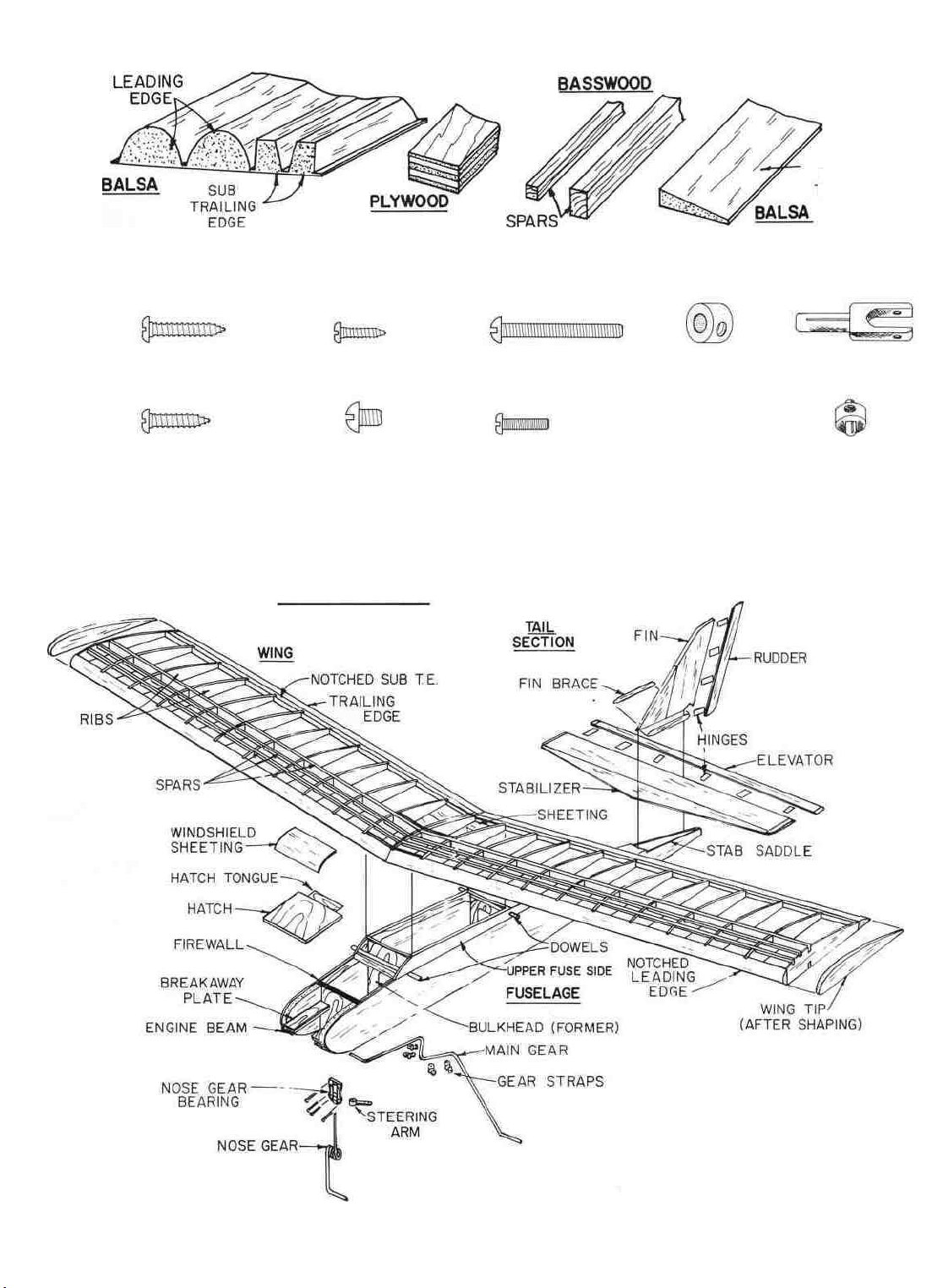
TYPES OF WOOD
HARDWARE
TAPERED
AILERON AND
TRAILING EDGE
STOCK
#4x5/8
#4x1/2"
SCREW
SCREW
#2x3/8"SCREW
6-32x3/16"
SCREW
PT40 PARTS
4-40x1"
2-56 x 3/8"
BOLT
SCREW
5/32"
COLLAR
AILERON
AILERON CLEVIS
CONNECTOR
CLEVIS
Page 6
GET READY TO BUILD
D 1. Unroll the plan sheet. Re- roll it inside out to
make it lie flat. Note: The fuselage plan is printed
on Side 1 and the wing plan is printed on Side 2.
D 3. Punch out all the die cut parts excepting the
sheets stamped "A" and "B". If a part does not come
out easily, cut around it with an X-Acto knife. Mark
the die cut parts before punching them out. Also
save any scrap wood until you are completely finished
building. You will use some scrap to build the model.
You will find that scrap wood is quite handy to use
for lots of things, like spreading epoxy for instance.
D 2. As you remove all parts from the box, use a felt
tip pen to write the name or number on each part.
To identify the parts, compare them with the plans
and with the die-cut parts patterns shown here:
DIE CUT PARTS PATTERNS
«
PT40W07 13 PER KIT WING RIBS 3/32x 3x12 BALSA
PT40F07 I PER KIT 1/8 x 3-7/8 x 12 3/4 PLY
C3
SERVO TRAY
FUSELAGE BOTTOM
PT40FIO 2 PER KIT 1/8 x 3-7/8 x 13-1/2 PLY
LOCKPLATES |
F-l
J
D 4. Separate the parts into four groups: 1-
FUSELAGE, 2- WING, 3- FIN & STABILIZER, 4HARDWARE
IMPORTANT: READ THIS BEFORE
STARTING TO BUILD
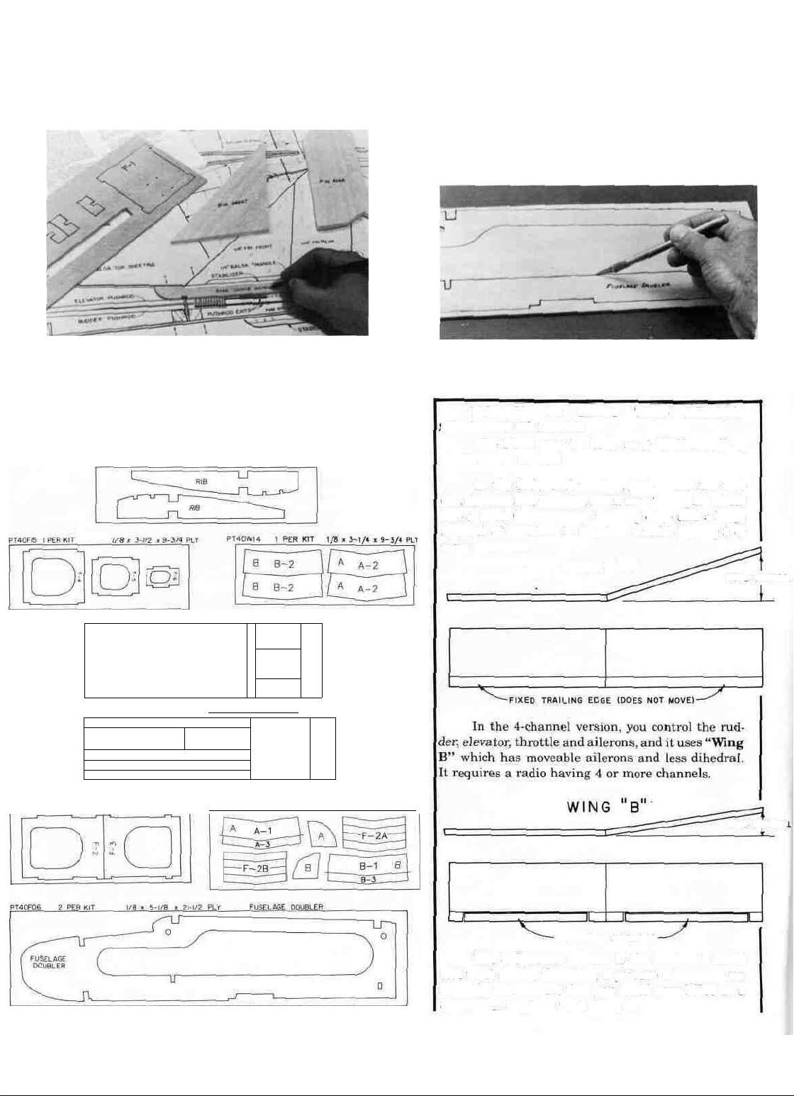
The PT40 may be built as a "3-Channel" or
"4-Channel" trainer.
In the 3-channel version, you control the rud-
der, elevator and throttle, and it uses "Wing A" which
has a fixed (non-moving) trailing edge and a large
amount of dihedral. It requires a radio having 3 or
more channels.
WING "A"
MORE DIHEDRAL
PT40F05 I PER
\^ STAB SADDLE DOUBLER /
KIT
1/8 x 3-7/8 x 9-3/4
PLY
PT40W15 1 PER
1
KIT____1/8 x 4-1/4 x 11-1/2
PLY
MOVEABLE AILERONS
The 3-Channel version is the easiest to build
and most stable; therefore, if you are a beginner we
strongly recommend that you build your PT40 as a
3-Channel airplane with Wing A.
LESS
DIHEDRAL
i
Page 7
The 4-Channel version has more ability to perform acrobatic maneuvers, but is more difficult to
build and its self-recovery characteristics are not
quite as good. If you already have some R/C flying
experience and are ready to move up to an airplane
that is more maneuverable, you may choose to build
your PT40 as a 4-Channel airplane with Wing B.
BUILD THE FUSELAGE SIDES
D 1. Take the two large 1/8" balsa fuselage sides
and put them together. Carefully line them up along
the bottom edge and the front. Tape them together
with a few pieces of masking tape along the bottom
edge to prevent them from moving. Now examine the
other edges to make sure the two fuselage sides are
exactly the same all around. If not, use a T-bar sander
with 100 grit sandpaper to lightly sand the edges to
match.
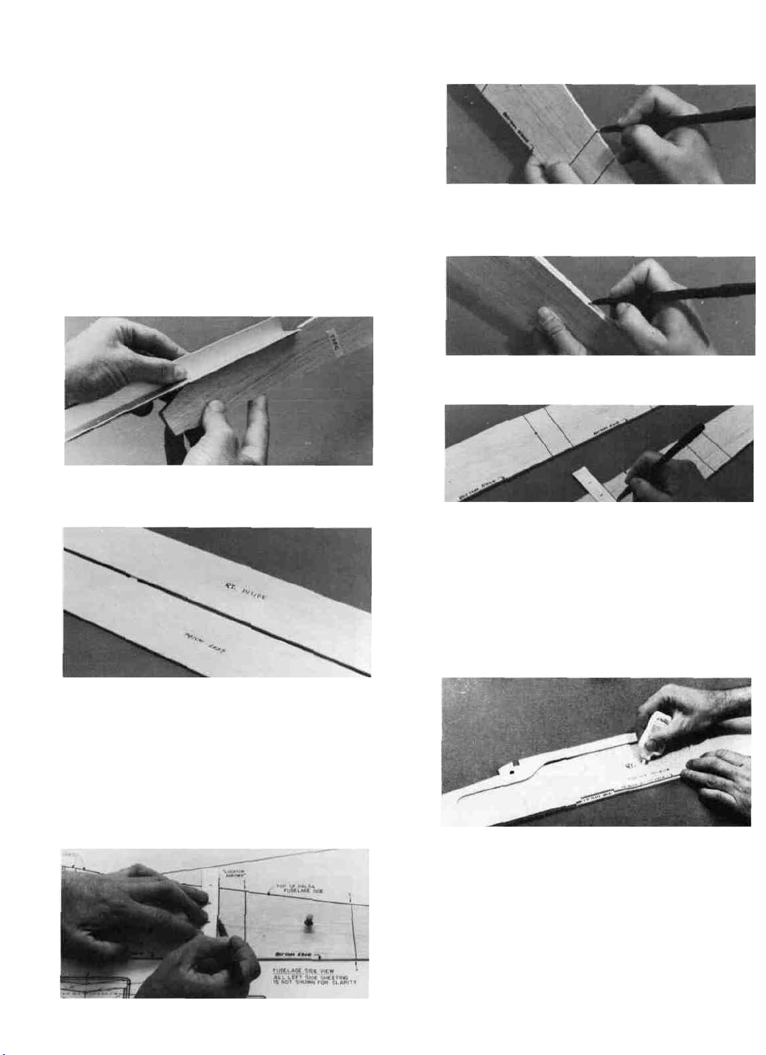
D 6. Remove the fuse side from the plan and make
small marks on the top and bottom edges, where the
lines end.
D 7. Put the two fuse sides together (inside to inside), and line them up carefully. While holding them
together, transfer the edge marks over to the left fuse
side edges as shown here.
D 8. Now draw lines on the left inside fuse side,
using the edge marks and a straight edge.
D 2. Now, with the tape still in place along the
bottom edge, let the two sides fall open and write
"Rt inside" and "Left inside" as shown here.
D 3. Tape the fuselage plan to your building surface.
D 4. Lay the right fuse (fuselage) side on the plan,
and carefully position it so the bottom edge and the
nose line up with the plan. Insert a few pins or tape
to hold it in place.
D 5. Using the "locator arrows", a straightedge
and a pen, draw six vertical lines on the fuse side as
shown. Press lightly to avoid damaging the balsa.
D 9. Lay the large 1/8" ply fuse doubler on the right
inside fuse side and position it to line up at the nose
and bottom edge. The part of the doubler which is
behind the L.G. plate area must be exactly 1/8"
above the bottom edge of the fuse side. Use a piece
of 1/8" balsa (such as the "windshield" piece) to check
this spacing. When you are satisfied that the doubler
is correctly lined up, apply thin CA glue all around
the edges while holding the doubler in place. Use
enough glue to make sure it flows under the plywood
to make a good bond.
D
10. Position
the
upper and
lower
"lock plates"
and
the stab saddle doublers on the right fuse side, using
the vertical guidelines previously drawn. The upper
lock plates and stab saddle doubler must be even with
the top edge of the fuse side. The three lower
lock plates
must
be positioned
1/8"
above
the
bottom edge of the fuse side. Use a piece of 1/8" balsa
as a spacer to aid in correct positioning of the bottom
lock plates.
Glue
these parts
in place
with thin
CA.
(See photo on next page.)
Page 8
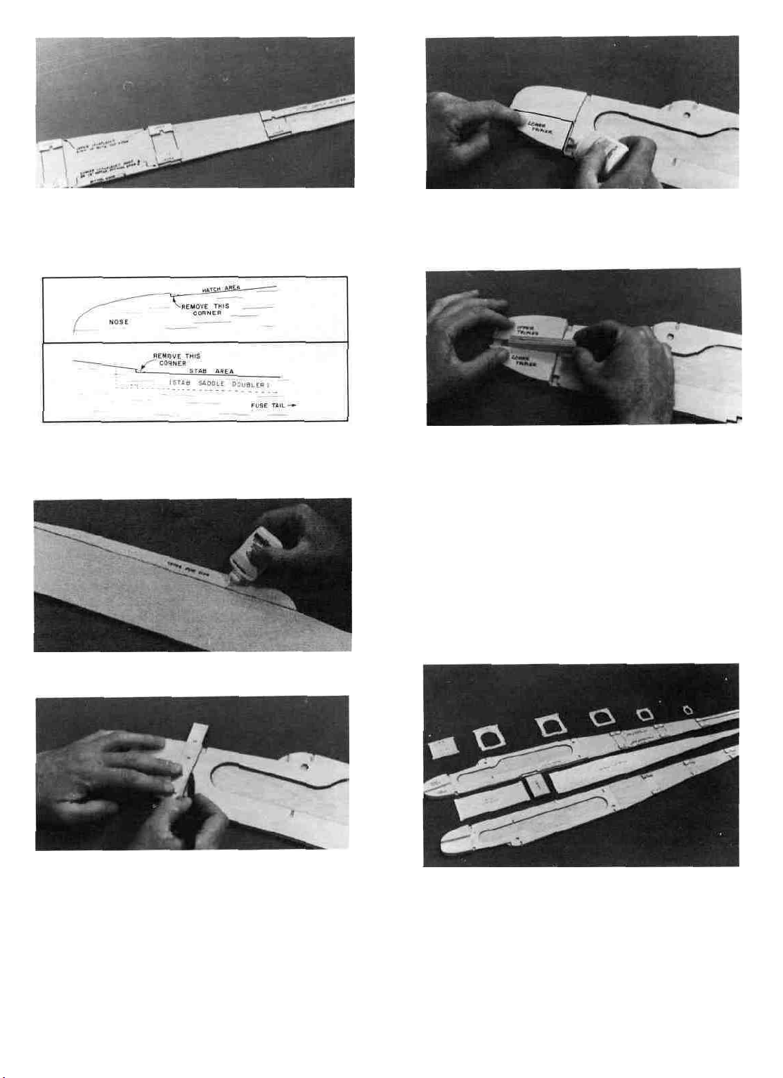
D 11. Notice that the 1/8" balsa fuse side has two
slightly rounded corners at the front of the "hatch"
area and at the front of the "stab saddle" area. Using
an X-Acto knife, cut away these rounded comers to
match the doublers.
D 15. Use one of the 3/8" ply engine beams as a
spacer to position the 1/4" balsa upper tripler. Move
the upper tripler forward or back until it lines up
with the line you drew in Step 13.
D 12. Turn the fuse side over and lay the 1/8" balsa
upper fuse side in place on the doubler, lining up
the curved "windshield" edge. Apply glue all around
the edges of this upper fuse side.
LI 13. Draw a straight line connecting the front edge
of the front slots in the fuse doubler.
D 16. Remove the 3/8" ply spacer, then glue the upper
tripler in place with thin CA all around the edges.
D 17. Glue the fuselage doubler, upper and lower
lock-plates, upper fuse side, stab saddle doublers and
the 1/4" balsa triplers to the left inside fuselage side.
Be sure to follow the same procedure as set forth in
steps 9-16 when doing so, but don't make two Rt.
fuse sides!
D 18. Drill or cut out the 5/16" holes in the fuse sides
for the wing hold-down dowels. If you use a drill, lay
the fuse side on a wood block for a backing to drill
into, which will prevent the balsa from tearing.
ASSEMBLE THE FUSELAGE
D 14. Lay the 1/4" balsa lower tripler in place on
the fuse doubler, and line it up with the line just
drawn and the edge of the doubler Glue the lower
tripler in place with thin CA all around the edges.
D 1. Before assembling the fuselage, make sure
that the following parts are set out within easy reach:
both fuse sides with doublers and triplers securely
glued on; formers F-l through F-6; 1/8" ply fuse bottom; 3/8" ply L.G. (landing gear) plate; 1/8" balsa
fuse bottom; the tapered balsa "fuse tail wedge" and
the six #62 rubber bands provided.
Page 9
Note: In the next steps you will assemble the
fuselage without glue! The interlocking parts enable you to do this so you can get everything together,
make sure the parts fit properly, check for straightness and make adjustments if necessary. Then you
will glue everything together by applying thin CA.
D 2. Make the "firewall" (Former F-l) by gluing
together the two 1/8" plywood parts which are marked
"F-l". Use 5 minute epoxy for this job. After the epoxy
has hardened, drill four 1/8" holes at the marks for
the nose gear bearing mounting holes.
D 3. Lay the right fuse side flat on the work surface.
Insert formers F-l and F-2 into their respective slots
in the right fuse side doubler.
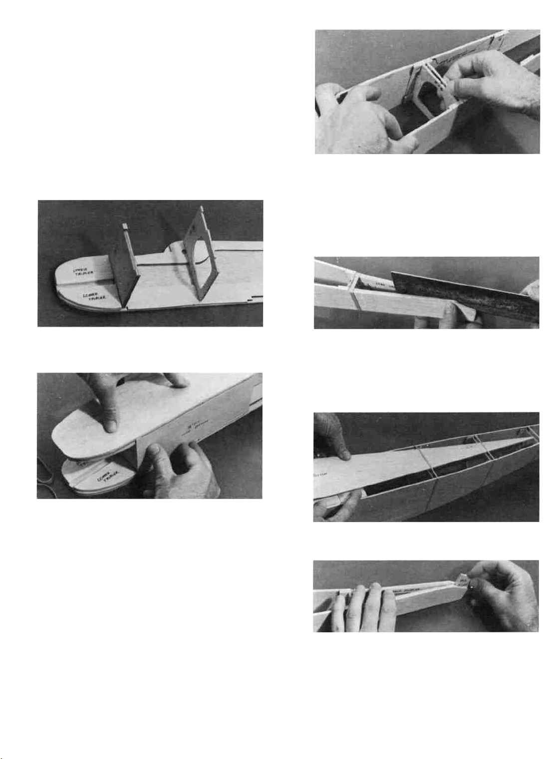
D 8. Put F-5 and F- 6 in place in the lock-plate
notches and secure with rubber bands.
D 9. Note that the rear end of the stab saddle doublers touch, preventing the rear ends of the fuse sides
from coming together. Using your T-bar, sand the
rear portions of both the stab saddle doublers as
shown until the rear ends of the fuse sides nearly
touch.
D 4. While holding F-l and F-2 upright, lay the left
fuse side in place on these formers. Now put the 1/8"
ply fuse bottom in place in the slots provided.
D 5. Holding these five parts together with one
hand, slide two #62 rubber bands over the nose, leaving one around F-l and one around F-2.
Note: Notice that the fuselage has now become
somewhat rigid and square. Before proceeding make
sure that the tabs in F-l, F-2 and the fuse bottom are
properly inserted into the slots in the fuse doublers.
Position the fuselage in its normal (upright) position
while inserting the other formers in the next steps.
D 6. Put former F- 3 in place and secure by sliding
a rubber band around the fuselage from the rear.
D 7. Slide another rubber band around the fuse to
the F-4 location, pulling the fuse sides together. Now
work F-4 into place in the lock-plate notches.
(See photo at top of next column.)
D 10. Turn the fuselage upside down and place the
3/8" ply L.G. plate into the slots provided. Secure
with masking tape.
D 11. Now take the 1/8" balsa fuse bottom and carefully slide it in place, narrow end first, under the
rubber bands, starting at F-3.
D 12. Finally, insert the tapered balsa fuse tail
wedge, and secure with a small rubber band or masking tape.
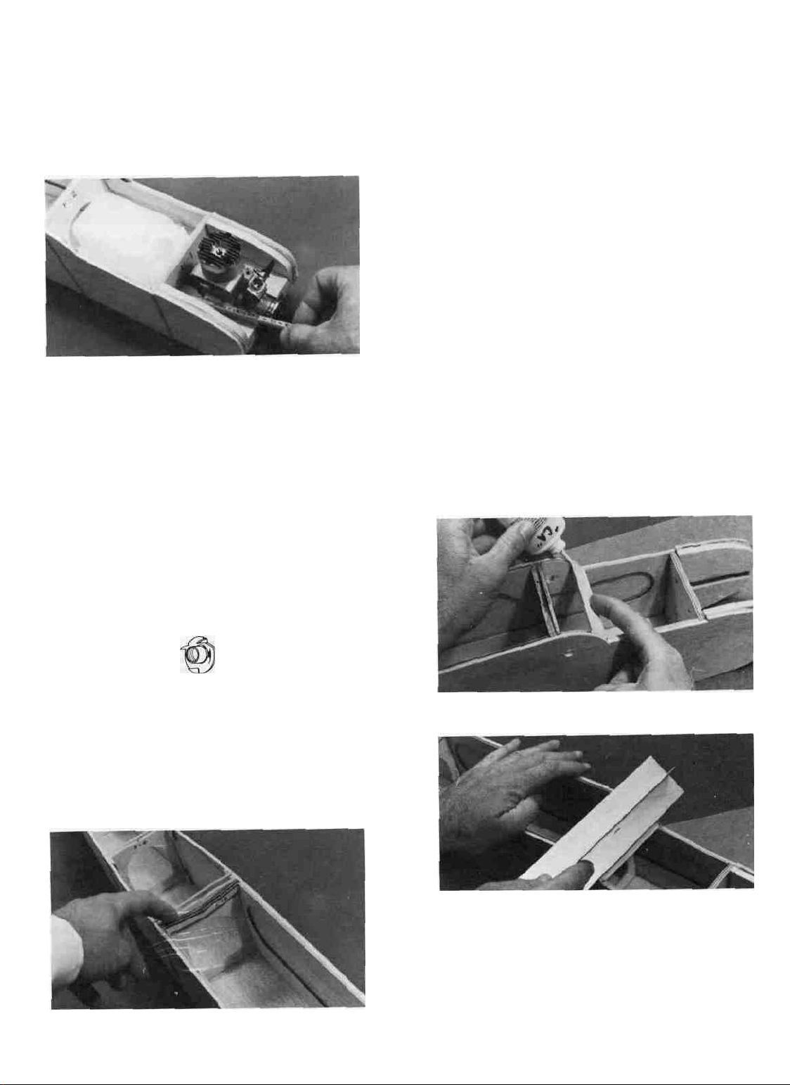
D 13. Temporarily install the 3/8" ply engine beams
and the 1/4" ply breakaway plates. Hold in place with
masking tape. Now position your engine on the
breakaway plates and your fuel tank behind F-l.
Don't worry about exact fits at this time. While holding these parts in position, determine where to drill
the holes in F-l for the fuel lines and the throttle
pushrod. (See photo and notes on next page.)
Page 10
NOTE ON ENGINES: The engine mount
"breakaway plates" have been cut to an average width
which will permit mounting almost any engine you
choose. However, you may have to trim these plates
slightly to fit your engine. The best way to do this is
to sand or file away a little at a time from the inside
edges of both breakaway plates until your engine fits
between the plates.
NOTE ON FUEL TANK: The PT40 requires
any 6 or 8 oz. fuel tank of your choice. Most tanks
have three possible openings, one for fuel pick- up,
and two for the fill/vent lines. We recommend that
you only use two lines. Run one line from the "klunk"
pick-up to the fuel fitting on the engine carburetor
and the other to the "pressure tap" fitting on the
muffler.
D 14. Because you have not yet glued the fuse parts
together, you may now carefully remove F-l and drill
the holes for the fuel lines and throttle pushrod.
D 18. Check your assembly of the fuselage, making
sure that all former tabs are in their respective
notches and all parts are in place. Set the fuselage
assembly on the plan top view. Your fuse assembly
should line up with the plan within 1/16". If not,
something is wrong and you should try to straighten
it out. If the alignment is far off and you can't find
the problem, consult with an experienced model builder to correct the problem before proceeding.
D 19. Lay down a 50" long piece of waxed paper to
protect your building surface. Set the fuselage assembly upright (in its normal position) on the waxed
paper. With everything in its proper place, apply thin
CA glue to all the joints, around the formers and
along the bottom. Wait a minute for the glue to set,
then apply thick CA to the joints to make sure a
good bond exists, especially in the joints that do not
fit perfectly. Note: The use of "Zip Kicker" or other
CA glue accelerator will be helpful when using thick
CA to fill any large gaps.
D 20. Remove the rubber bands from the fuselage.
In the above step you may have glued the rubber
bands to the wood in some places. If so, just cut the
rubber away from the wood with an X-Acto knife.
INSTALL THE WINDSHIELD
AND HATCH
D 1. Put the 1/2" balsa triangle windshield brace
in place and apply thin CA glue.
D 15. Insert four 4-40 blind nuts part-way into the
1/8" holes previously drilled. Insert them from the
back side of F-l. Apply one drop of thick CA glue
under the wide part of each nut, then immediately
press them firmly in place with a pliers or a vise.
4-40 BLIND NUT
D 16. Replace F-l back into the fuse.
D 17. By now you should have decided which wing
you are going to build, "Wing A" (without ailerons),
or "Wing B" (with ailerons). If you have chosen'
"Wing A", find the four F-2A wing saddles and put
them into the slots behind F-2 and in front of F-3. If
you have chosen "Wing B", use the F-2B saddles.
D 2. Sand the 1/2" balsa triangle to match the curve
on the fuse sides.
D 3. Sand the bottom edge of the l/8"balsa
windshield at an angle so it will rest flat on the fuse
sides.
D 4. Apply thick CA to the 1/2" balsa triangle, then
immediately place the windshield in position, holding the bottom against the triangle.
10 (See photo, top of next page.)
Page 11
D 5. Wet the top surface of the windshield so the
wood will bend without breaking.
D 6. Apply thick CA to the top of F-2 and the fuse
sides where the windshield will contact, then immediately bend the windshield down and hold until
the glue sets
D 7. Trim any excess windshield even with the back
edge of F-2.
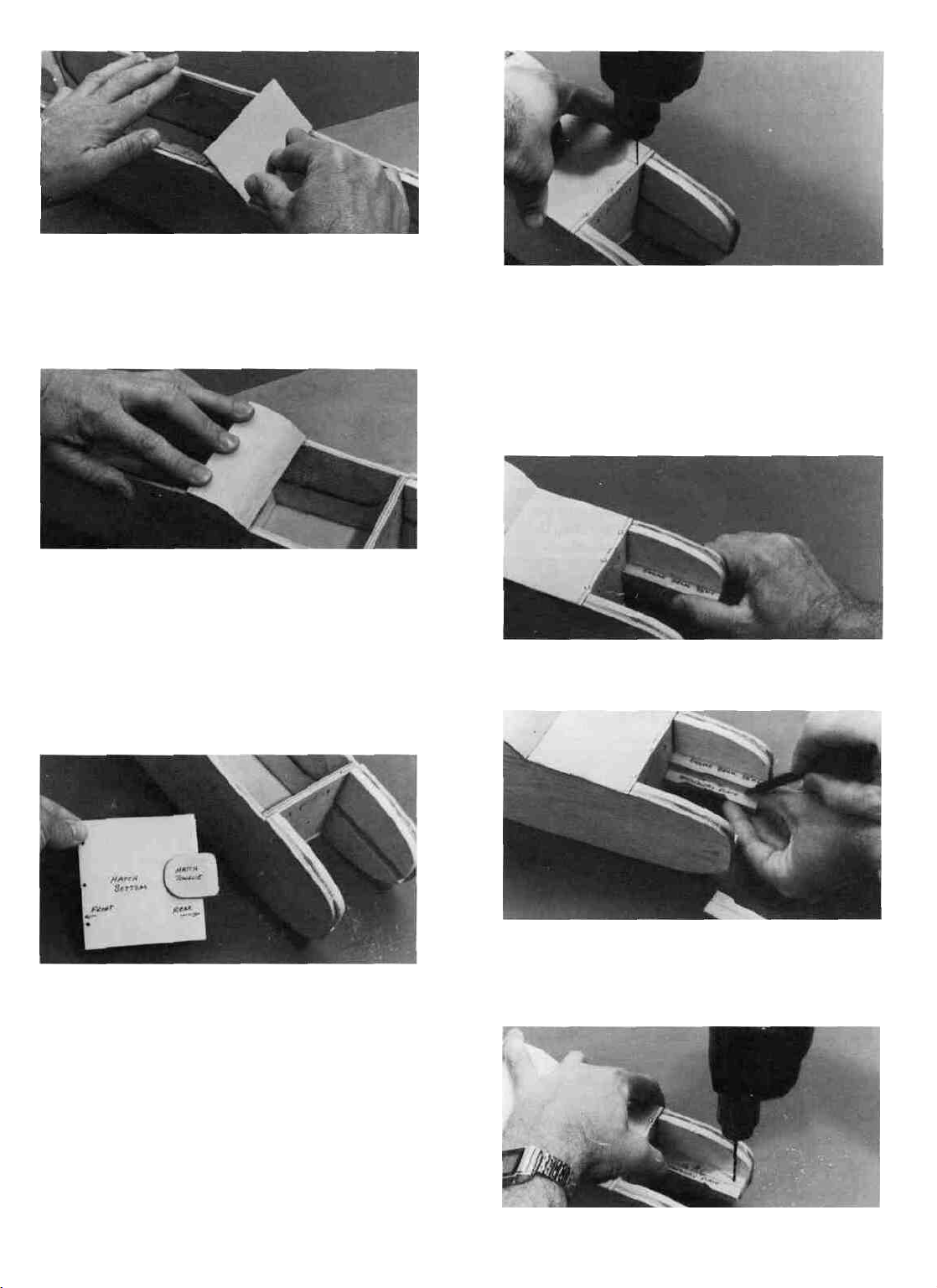
D 8. Taper the rear edge of the 1/8" ply hatch to fit
the windshield as shown on the fuse plan side view.
D 9. Find the piece of 1/8" ply that you punched
out of F-5. This is used as the hatch tongue. Glue the
hatch tongue to the bottom of the 1/8" ply hatch with
thick CA. Let the hatch tongue extend about 1/2"
beyond the back edge of the hatch.
MOUNT THE ENGINE BEAMS AND
BREAKAWAY PLATES
D 1. Glue the 3/8" ply engine beams in place using
5 minute epoxy. With a tissue, wipe off any excess
epoxy that squeezes out when sliding the beams into
the slots. Allow the epoxy to fully cure before disturbing the beams.
D 2. Holding the 1/4" breakaway plate under the
3/8" ply beam, draw a line on the breakaway plate
to mark the edge of the beam.
D 10. Draw a guideline 1/8" back from the front edge
of the hatch. This is the centerline of the three hatch
hold down screws.
D 11. Holding the hatch firmly in position, drill three
1/16" holes along the guideline •
D 12. Remove the hatch and re-drill the holes in the
hatch only to 3/32". Then attach the hatch to the fuse
with three #2 x 3/8" screws. (See photo, top of next
column.)
D 3. Now place the breakaway plate on top of the
beam and while holding the plate firmly in place,
drill three 3/32" holes as shown, drilling down
through the breakaway plate and the beam. Do this
for both plates and beams.
11
Page 12
D 4. Remove the breakaway plates and re-drill the
holes in the breakaway plates only to 1/8".
D 5, Fasten the breakaway plates to the beams
using six #4 x 5/8" screws.
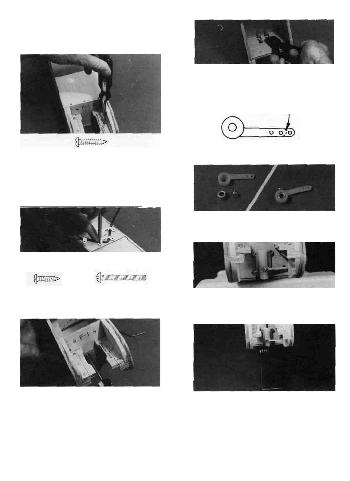
PREPARE THE NOSE GEAR
D 1. Referring to the steering arm drawing here,
cut off about 3/16" of the steering arm so it will clear
the fuse triplers. Drill out the end hole to 5/64"diameter for pushrod wire clearance.
TRIM 3/16" HERE
#4x5/8"
INSTALL THE LANDING GEAR
D 1. Turn the fuselage upside down and position
the 5/32" wire main L.G. (landing gear) on the ply
L.G. plate. Set the four nylon L.G. straps in place
and mark the location for the eight screw holes. Drill
3/32" (or slightly smaller) holes at the marks.____
D 2. Temporarily mount the main LG using the
nylon straps and the #4 x 1/2" screws.
#4x1/2"
D 3. Temporarily mount the nylon nose gear bearing
using four 4-40 x 1" bolts screwed into the 4-40 blind
nuts previously installed.
SCREW
SCREW
4-40x1" BOLT
D 2.Assemble the nose gear steering arm which
consists of a nylon arm, a 5/32" wheel collar and a
6-32 x 3/16" screw.
D 3. Place the steering arm assembly into the nose
gear bracket making sure that the wheel collar opening on the steering arm is down and the screw is
facing out.
11
D 4. Referring to the nose gear diagram on the plans,
slide the nose gear wire through the holes in the
nose gear bearing and wheel collar/steering arm.
Tighten the screw, making sure the steering arm is
at the angle shown on the top view of the fuselage.
D 4. If you are a young person, you should ask
an adult to help you with the following step:
Using a side cutter, cut off the excess bolt length
sticking out behind F-l. You must wear eye protec-
tion when doing this! Note: An alternate method
is to mark the bolts with an indelible marker, remove
them from F-l, and cut them off at the marks with
a side cutter, hacksaw or a Dremel cut-off wheel.
(See photo, top of next column.)
CUT THE NOSEGEAR PUSHROD
OPENING
D 1. Mark and drill a 1/8" hole through Former F-l
in the position shown on the F-l drawing on the plan.
This hole is for pushrod clearance.
See photo, top of next page
12
Page 13

CUT THE PUSHROD EXIT SLOTS FOR
THE RUDDER AND ELEVATOR
D 1. Find the location of the "Pushrod Exits" on
the fuselage plan (side view). Measure their locations
in relation to the fuse bottom and the back of F-6,
and transfer these measurements to your fuselage.
Note that the pushrod exit shown in dashed lines is
for the rudder pushrod exit on the left fuselage side.
D 2. Cut out the slots with an X-Acto knife.
This completes the fuselage construction for
now. Note that you have not yet installed the top
sheet. Set the fuselage assembly aside.
BUILD AND INSTALL THE "TAIL
FEATHERS"
Q 1. Working on waxed paper on a flat surface, glue
the 1/4" balsa fin front to the 1/4" balsa fin rear
using thin CA. Immediately wipe off any excess glue
to make sanding easier. Apply glue to both sides of
the joint.
D 3. Find the two 1/4" x 1/4" x 5-7/8" balsa pieces.
These are used for the ends of the stab and elevator.
Cut a 1-3/8" length from each of these pieces and
glue them to the ends of the elevator using thin CA
glue. Sand the ends even with the elevator using a
sanding block.
D 4. Take the two remaining pieces of 1/4" x 1/4"
balsa and glue them to the ends of the stab and sand
to blend in.
D 5. Round the corners of the fin, rudder, stab and
elevator as shown on the plan.
D 6. Sand the fin and stab smooth with a T-bar
sanding block and 100 grit sandpaper.
D 7. Put the elevator and stab together and sand
the tips to the same length.
D 8. Using a sanding block, sand the following to
a rounded shape: stab leading edge (excepting the
flat center portion), stab tips, elevator trailing edge
and tips, fin leading edge, fin tip, rudder trailing
edge and rudder tip.
D 9. Using a fine point felt tip marker, carefully
draw a centerlirie all along the stab trailing edge,
elevator leading edge, fin trailing edge and rudder
leading edge.
D 2. In the same manner, glue the stab (stabilizer)
front to the stab rear.
D 10. Using a T- bar sanding block with 100 grit
sandpaper, sand the elevator leading edge and rudder
leading edge to a "V" shape. Work slowly and care-
fully so you don't sand away too much balsa. When
you have finished, the centerlines you previously
drew should remain, and the "V" shape should look
like the sketch shown above the fin on the plan.
13
Page 14

MAKE THE HINGES
D 1. Take the 9" strip of hinge material and roughen
both sides with 220 grit sandpaper. This is best done
with a small piece of sandpaper held with your fingers, rather than a sanding block. Do not sand the
centerline of the hinge material.
D 2. Using a ruler and a ball point pen, draw lines
dividing the hinge material into eighteen 1/2" -wide
segments.
D 2. While holding the elevator in place against
the stab trailing edge, transfer the hinge locations
to the elevator leading edge.
D 3. Repeat the above process marking the hinge
locations on the fin and rudder. Don't forget to mark
the bottom hinge location on the rudder.
CUT THE HINGE SLOTS
D 3. Drill four 1/16" holes in each of the hinge segments as shown on the plan. Use a wood block as a
backing to drill into when drilling these holes.
D 4. Fold the hinge material back and forth a few
times on the centerline to "condition" the hinges.
D 5. Cut the hinges apart with a scissors on the
lines you previously drew. Also snip off a small piece
of each hinge comer.
D 1. Move the fin trailing edge close to the table
edge. Place a small piece of 1/8" plywood (from die-cutting scraps) next to the hinge slot location.
D 2. Hold your X-Acto knife straight on the scrap
wood and cut straight into the fin. The slots should
be about 1/2" deep (enough for half of the hinge to
fit into).
D 3. Trial fit by pushing the hinges (no glue) into
the slots to make sure you have cut the slots wide
enough and deep enough.
D 4. Repeat this process for the rudder, elevator
and stab.
MOUNT THE STAB ON THE FUSE
D 1. Remove the nylon nose gear bearing and the
main gear from the fuselage.
Note: You should end up with 18 hinges, 8 of
which you will use for the ailerons if you are building
the "B" wing.
MARK THE HINGE LOCATIONS
D 1. Lay the stab on the plan and mark the hinge
locations on the stab trailing edge (both sides are
the same).
D 2. Lay the stab on the plan and carefully line it
up with the outside lines. While holding it in this
position, lay a straight edge along the "fuselage cen-
terline" as shown on the plan. Draw the fuselage
centerline on the top of the stab with a fine point
marker. Work as carefully as you can when doing this!
(See photo, top of next page)
14
Page 15

D 3. With the fuse on a flat surface, lay the stab
in place on the fuselage in the stab saddle area with
the front of the stab touching the rear surface of F-6
and centered side-to-side.
D 4. While holding the stab firmly in place onto
the saddle, measure down to the flat work surface
from both ends of the stab. If one side is higher than
the other, sand the high side of the stab saddle with
your T-bar sanding block and 80 or 100 grit
sandpaper. Replace the stab in the saddle and recheck the measurements. Continue this process until
the stab is level within 1/16".
the stab slightly until both measurements are the
same within 1/16" .
E- When you finally have the stab accurately
aligned on the fuse, make four little "alignment
marks" on the stab where the leading and trailing
edge of the stab intersect with the outside edges of
the fuse sides. You will use these marks to quickly
and accurately position the stab when gluing it in
place. Now remove the stab.
F- Mix up a batch of epoxy and spread it on the
stab saddle and the back of F-6. Lay the stab in place
using the "alignment marks" for positioning. Before
the glue sets, re-check the measurements in step D.
Hold or pin the stab in place until the glue sets.
NOTE: READ THROUGH AND PRACTICE THE NEXT 6 STEPS (A-F) BEFORE PROCEEDING.
D 5. Now glue the stab securely to the stab saddle
with 5 minute epoxy. (You may perform this step with
5 minute epoxy, but a slower curing epoxy will give
you more time to make sure the alignment is correct.)
It is important that the stab be centered and square
on the fuselage; so, follow this procedure exactly:
A- With a ruler, measure to find the exact center
of the top of F-3. Stick a pin in at this point.
B- Also measure to find the center of the top
of F-6 and mark this point with a pencil.
C- Lay the stab in the saddle and line up the
"fuse centerline" (which you previously drew on top
of the stab) with the mark on F-6 and with the center
joint at the rear of the fuse.
MOUNT THE FIN TO THE STAB
Note: Probably the single most troublesome
cause of poor flying models is improper fin alignment.
Therefore, you should take the time and care necessary to do your "best when performing this next set
of steps. Read through the next five steps before
beginning!
D 1. At the front and back of the "fuse centerline"
which you previously drew on the top of the stab,
make accurate marks 1/8" right and left.
D 2. Using a straight edge and a fine point marker,
connect these marks, making two parallel lines, one
on each side of the fuse centerline.
D- Check the "squareness" of the stab by
measuring from the rear corners of both stab tips to
the pin in the center of F-3. Adjust the position of
15
Page 16

D 3. With the rudder attached to the fin by the top
three hinges (not glued in), trial fit the fin onto the
fuse. If the rudder is too long and touches the flat
work surface preventing the fin from resting on the
stab,
sand a small amount
D 4. Apply 5 minute epoxy to the bottom of the fin
and position the fin between the guidelines you previously drew. Slide the fin/rudder assembly forward
until the bottom of the rudder just touches the back
of the fuse. Wipe away any excess epoxy with a tissue.
D 5. Before the epoxy sets, check the squareness
of the fin with the stab, using a small carpenter's
off
the
bottom
of
the
rudder.
square or draftsman triangle. Hold position until the epoxy sets firmly.
D 8. Now temporarily assemble the elevator to
the stab and the rudder to the fin. Swing the rudder
from side to side and the elevator up and down. The
rudder and elevator must not touch in any position! If they do, carve or sand the notch in the rudder
to insure that they will not bind. In addition, make
sure no part of the fin interferes with the free upward
movement of the elevator.
Lay the fuselage assembly aside for now.
CHARGE YOUR NICAD BATTERIES
D 1. Read the instruction manual for your radio
system to become familiar with how to hook it up.
D 6. Find the two 4-7/8" lengths of l/4"balsa triangle
and sand the ends to a rounded (or pointed) shape
as shown on the plan. Trial fit these pieces in place
at the fin/stab joint. Later, when you are covering
the model (and before you cover the fin and stab)
cover the outer surface of these triangular pieces,
leaving about l/8"of excess covering all around the
edges. Then glue these pieces in place and iron down
the excess covering to the fin and stab
D 2. Charge your transmitter and receiver bat-
teries now so they will be ready when you need them.
Note: Charge the batteries for the time recom-
mended for the first charge...usually 18-24 hours.
BUILD THE WING PANELS
NOTE: Like the fuselage, the PT40 wing is
made to fit together without glue, so you can assemble all of the major parts and check to make sure
they are all lined up before applying thin CA to the
joints.Thick CA will be added after the thin CA has cured.
D 1. Turn the plan over to side 2, which shows the
wing. Tape or pin the plan to your flat work surface
so the "Right Wing Panel" is facing you. Cover the
right wing panel drawing with waxed paper (so you
won't glue the wing to the plan!).
D 2. The shaped and notched wing leading edge
(L.E.) and trailing edge (T.E.) are fastened together
by a thin layer of balsa. Separate them by folding
until the balsa breaks. Sand away the excess balsa
that remains along the edges after breaking them
apart, using a T-bar with 100 grit sandpaper.
D 7. You previously marked the four hinge loca-
tions on the rudder. Now transfer the bottom hinge
location over to the rear of the fuse. Cut the hinge
slot in the tapered balsa fuse tail filler.
(See photo, top of next column.)
16
Page 17

D 3. Before using the L.E. and T.E. pieces, you must
determine which pieces are to be used for the right
wing panel. Here's how:
A- We have drawn red lines on the top of each
piece.
B - Notice that the pieces are notched on one
end, but not on the other. The notched end goes toward
the wing tip, and the end without a notch goes toward
the center of the wing.
C- Take one of the L.E. pieces and lay it on the
right wing panel plan with the red line up. If the
notched end is on the right side (at the tip) you have
the correct L E.
D- Do the same thing to determine which T.E.
piece to use.
D 4 Tape one of the 3/8" x 1/2" basswood spars to
the plan, with the right end of the spar lined up with
the tip. The excess spar length must extend past the
wing centerline.Apply tape in 3 places, between the
ribs, near the ends and in the middle.
D 6. Insert the fronts of the ribs into the notches
in the balsa leading edge (L.E.).
D 7. Insert the backs of the ribs into the notches
in the balsa trailing edge (T.E.).
D 8. Adjust the position of the leading edge and
trailing edge left or right so they match the plan at
the right tip. Tape or pin them to the plan so they
don't move.
D 9. The tip rib should now match the plan exactly.
However, due to shrinkage or expansion of the paper,
the other ribs may not line up perfectly. That is OK,
because the notches in the L.E. and TE. are cut in
the right places. Before proceeding, make sure none
of the ribs are bowed (curved). If they are, straighten
them by sliding the center part right or left on the
spar.
D 10. Insert the top 3/8" x 1/2" spar into the top
notches in the ribs, so the right end is even with the
tip
rib.
D 11. Insert two of the 3/16" x 3/16" basswood spars
into the small notches in the top of the ribs, so the
right ends are even with the tip rib.
D 5. Remove the 3/32" balsa wing ribs from the die
cut sheets and slide 12 ribs into place on the bottom
spar, using the plan to get them close to their proper
position DO NOT PUT A RIB AT THE CENTER-
LINE.
D 12. Make sure that the ribs are all down onto the
plan and fully inserted into the notches in the L.E.
and
T.E.
17
Page 18

D 13. Apply thin Ca to all joints. After the thin CA
has cured, apply some thick CA to each joint.
D 14. Find the die-cut plywood sheets containing the
Dihedral Braces, Wing Braces, F-2's and Gauges
(PT40W14 & PT40W15). If you are building wing "A"
(without ailerons), punch out all the parts that apply to the
"A" wing. Compare each part with the drawings on page
6 and mark them with their correct letter and number (A-
1, A-2, etc.). If you are building the "B" wing, use only
the parts with a "B" on them.
D 15. Using the "dihedral gauge" (A or B, depending
on your wing choice), draw cut-off lines on the back
of the L.E. and the front and back of the spars and
T.E. (See the sketch on the plan showing how to do
this.) The point of the dihedral gauge must be
exactly on the centerline when marking the cutoff lines.
D 16. Using a razor saw (or any fine-toothed saw),
carefully cut off the L.E., spars and T.E. on the lines
you just drew.
Clamp or hold the parts until the glue hardens.
Set the right wing panel aside, and turn the
plan around so the left wing panel is facing you.
D 18. Build the left wing panel in the same manner
as you did the right panel, following steps 1 through
16.
JOIN THE WING PANELS
D 1. Lay the left wing panel flat on the building
surface or a large flat table. Place a sheet of waxed
paper under the "center" portion of the panel where
it will be joined to the right half.
D 2. Slide the right wing panel into position, so
the spars touch the spars of the left panel. Block up
the right tip with a stack of books The stack of books
must be 8" high for wing A and 5" high for wing B.
D 17. Using 5 minute epoxy:
Glue A-l or B-l to the back of the leading edge.
Glue A-2 or B-2 to the front of the main spars.
Glue A-2 or B-2 to the back of the main spars.
Glue A-3 or B-3 to the front of the trailing edge.
D 3. Check to make sure the L.E., spars and T.E.
are touching. If not, sand off any long ones slightly
until they all touch. Now slide the panels apart.
NOTE: PRACTICE THE NEXT STEP
"DRY" BEFORE ACTUALLY DOING IT!
D 4. Mix up a batch of epoxy (30 minute epoxy is
preferred here to give you more time, or 5 minute
epoxy may be used if you work quickly), and apply
it to the dihedral braces, L.E., spars and T.E. Slide
the panels together and wipe up the excess glue with
a tissue.
Make sure the wing panels remain in posi-
tion until the epoxy has fully hardened.
Remove any excess glue with a tissue.
NOTE: Skip to page 39 and add the
shear webs as described on that page.
18
Page 19

INSTALL THE CENTER RIBS AND
BOTTOM SHEETING
LI 1. After building the wing, you have two ribs
remaining. Lay these ribs, one at a time, on the drawing in the lower left comer of the wing plan. With a
straight edge and a pen, mark the four cut-off lines,
using the arrows as a guide.
D 2. Cut the ribs at the cut-off lines using a razor
saw.
D 3. Place the two "front parts" together and the
two "aft parts" together, and apply thin CA glue
around the edges.
D 6. Working on waxed paper, glue the bottom
sheeting to the inside edges of the ribs and dihedral
braces.
D 7. Turn the wing upside down and inspect the
bottom of the center section. If there are any major
gaps between parts, fill them with balsa dust (from
sanding) and apply thin CA.
D 8. Sand the bottom of the center section smooth
with a sanding block and 100 grit sandpaper.
At this point the bottom center section should
look like this:
INSTALL TAPERED TRAILING EDGE
(WING A ONLY)
D 4. Position these center rib parts in place in the
center of the wing and glue them to the L.E..spars
and T.E. You may use thin CA if the ribs fit perfectly;
otherwise use thick CA or epoxy.
D 5. From the sheet of 1/8" x 3" x 13" balsa, cut
rectangles to fit between the center rib and the 2nd
rib in both wing panels The easiest way to do this
is to lay the wing right on the 1/8" balsa sheet and
trace around the inside edge of the ribs and spars as
shown here.
Note: The following 7 steps apply only to wing
A (without ailerons). If you are building Wing B, skip
to the next section now.
D 1. Find the two tapered balsa T.E. pieces. They
are 1-3/16" wide and 30" long.
D 2. Place one of the trailing edge pieces against
the rear edge of the right wing panel on a flat surface.
If there is a 3/32" gap along the top edge, that means
the T.E. is upside down If so, turn it over.
D 3. Working on a flat surface covered with waxed
paper, hold the tapered T.E. firmly against the rear
edge of the Rt. wing panel with the left edge at the
wing centerline, and apply thin CA along the joint.
Make sure the wing and the T.E. are down flat on
the work surface when doing so.
Note: The grain of this bottom sheeting must
run in the same direction as the spars.
D 4. Take the other tapered T.E. and determine
which side goes up, as in step 2.
D 5. Trial fit this piece in place against the rear
edge of the Left wing panel. You will probably notice
that there is a gap on the bottom, where the two T.E.
pieces come together. If so, sand the end of the T.E.
so it fits snugly against the end of the right T.E.
D 6. Glue the left tapered T.E. in place, as in step 3.
19
Page 20

D 7. With a razor saw, cut off the ends of the tapered
trailing edges even with the tip ribs.
INSTALL TRAILING EDGE, AILERONS
AND TORQUE RODS (WING B ONLY)
Note: The following 27 steps apply to wing B
(with ailerons). If you are building wing A, skip to
the next section now.
D 1. Find the two tapered balsa T.E. (trailing edge)
pieces. They are 1-3/16" wide and 30" long.
D 2. Place one of the T.E. pieces against the rear
edge of the right wing panel on a flat surface. If there
is a 3/32" gap along the top edge, that means the T.E.
is upside down. If so, turn it over.
D 3. Just below the right wing drawing (on the
plan), there is a separate drawing showing the aileron
details. Using this drawing as a guide, cut the tapered
T.E. into three parts. Label these parts: "Rt. inboard
T.E.", "Rt. Aileron" and "Rt. outboard T.E."
("Rt." is an abbreviation for "right".)
There are several ways to accomplish this, so
you may choose one of these:
A- File the groove with an 1/8" or 5/32" diameter
round file, available at hardware stores (this type
of file is normally used to sharpen small chain saw
teeth).
B- Cut the groove with a 5/32" outside diameter
brass tube. You can sharpen the tube by cutting
around the inside of one end with an X-Acto knife.
C- Cut the groove by running the T.E. piece
over a small table saw, with the blade set at the
height needed to cut a groove 5/32" deep.
D- Rout the groove out with a Dremel Moto
Tool and a 1/8" bit.
D 7. Turn the two inboard T.E. pieces upside down
as shown in the following photo, and measure 7/16"
out from the "wing centerline". At the 7/16" point,
cut a notch in both pieces with an X-Acto knife, pro-
viding free movement for the threaded portion of the
aileron torque rods.
D 4. Glue the Rt. outboard T.E. piece to the rear
edge of the right wing panel. The outer edge of the
T.E should be even with the tip as shown on the plan.
D 5. Repeat steps 1-4 for the left side, making the
"Lt. inboard T.E.", "Lt. Aileron" and "Lt. outboard
T.E." ("Lt." is an abbreviation for "left".)
D 6. Find the "aileron torque rods". You will
notice that there is a black nylon tube on each of the
bent rods. This nylon tube is called the "torque rod
bearing". You must now make a groove in the front
edge of each inboard T.E., so the torque rod bearing
may fit into the groove.
D 8. Roughen the surface of the nylon torque rod
bearings using a piece of 100 grit sandpaper.
D 9. Slide the nylon torque rod bearings as far as
they will go toward the threaded portion of the torque
rods.
D 10. With a toothpick, apply a small amount of
petroleum jelly (Vaseline, etc.) around the torque rod
where it enters the nylon bearing. This will help
prevent any excess glue from getting in and possibly
"locking up" the torque rod.
D 11. Place the torque rods into the grooved T.E.
pieces.
STOP! AT THIS POINT YOU MUST CAREFULLY STUDY THE PLANS AND PHOTOS TO
MAKE SURE YOU HAVE THE RIGHT TORQUE
ROD IN THE RT. INBOARD T.E., AND THE
LEFT TORQUE ROD IN THE LT. INBOARD T.E.
THE THREADED PORTION MUST COME OUT
THE BOTTOM, AND THE SHORT BENT END
MUST POINT TOWARD THE REAR.
20
Page 21

D 12. If the nylon bearing fits snugly into the groove,
you may use a few drops of thin CA to glue it in place.
If you have a loose fit, use thick CA or epoxy. DO
NOT GET GLUE INTO THE ENDS OF THE
NYLON BEARING TUBE!
D 13. Turn the wing upside down, with the trailing
edge facing you, and temporarily position the inboard
T.E. pieces against the back edge of the wing. You
will notice the gap between the pieces, caused by the
dihedral angle. Sand the ends of the inboard T.E.
pieces so they come together without a gap.
D 14. With the T.E. pieces taped in their proper position mark the location of the slots (where the
threaded portion comes out) on the back edge of the
wing as shown. Then remove the T.E. pieces and cut
slots in the back edge of the wing.
D 19. Sand the leading edge of the ailerons to a "V"
shape as shown on the plan.
D 20. Groove the leading edge of each aileron to
accept the torque rods.
D 21. Trial fit the ailerons onto the torque rods.
D 22. Cut or sand a small amount off both ends of
the ailerons to provide about 1/16" to 3/32" of clear-
ance at each end. (Remember....the ailerons will be
covered with Super Monokote or other covering material; therefore you must make some space at the
aileron ends so they don't tighten up after covering.)
D 23. Remove the ailerons and draw a centerline
down the back edge of the wing, in the aileron opening.
D 24. Place the ailerons on the wing plan and mark
the locations of the hinges on the leading edge of the
ailerons. Now put the ailerons back in place on the
wing and transfer the hinge location marks to the
back edge of the wing.
D 15. Glue the inboard T.E. pieces to the back of the
wing by carefully holding or taping the pieces in
place and applying thin CA in small drops along the
joints. Use care to avoid getting glue inside the nylon
bearings.
D 16. Mark a centerline all the way down the leading
edge of each aileron.
D 17. Hold the ailerons in place against the back
edge of the wing and mark the location where the
torque rods will enter the ailerons.
D 18. Drill a 3/32" hole in each aileron to accept the
torque rods.
D 25. Cut the hinge slots for the ailerons in the
same way that you did for the elevator and rudder.
D 26. Using 100 grit sandpaper, roughen the ends
of the torque rods that will go into the ailerons.
D 27. Trial fit the ailerons on the wing with the
hinges in place. DO NOT GLUE THE HINGES IN
UNTIL AFTER COVERING.
THE FOLLOWING INSTRUCTION
PHOTOS SHOW THE "B" WING (WITH
AILERONS), BUT THE PRINCIPLES APPLY
TO BOTH "A" AND "B" WINGS.
INSTALL THE WING TIPS
D 1. Sand the wing tips smooth and flat with your
T-bar and 100 grit sandpaper.
D 2. Find the two tapered balsa pieces that are
11-3/8" long. These are the wing tips.
D 3. Holding the wing and wing tip on a flat surface
covered with waxed paper (the narrow edge of the
tapered piece goes down), apply thin CA glue to the
joint.
(See photo, top of next page.)
21
Page 22

D 4. Carve and sand the wing tip to blend in with
the
tip rib, L.E. and
T.E.
D 5. Sand the front and rear comers to a rounded
shape as shown on the plan. Also sand the top and
bottom edges to a slightly rounded shape.
SAND THE WING SMOOTH
D 5. Apply thin CA glue around the edges, holding
the plates firmly in place until the glue sets.
TRIAL FIT THE WING IN THE SADDLE
D 1. Using your T-bar sander, sand the inside edge
of the plywood fuse side doublers at the same angle
as the F-2A or F-2B formers.
D 2. Lay the wing in place on the fuselage with
the T.E. resting against the front of F-3.
D 3. Notice that the center of the wing L.E. rests
on the top rear portion of the windshield, preventing
the wing from resting down onto the fuse sides. Mark
the area of the windshield that needs to be cut away.
D 1. Lightly sand the entire wing with your T-bar
and 100 grit sandpaper. Pay special attention to
blending the ribs in with the leading and trailing
edges and spars and removing any excess glue residue that would cause bumps when the covering is
applied later.
D 2. Now lightly sand the wing again with a Tbar and 220 grit sandpaper. After this step, the wing
should be very smooth and ready for covering.
INSTALL THE WING PLATES
D 1. Find the two pieces of 1/32" x 3/4" x 1-1/2"
plywood. These are the "Wing Plates" which protect
the trailing edge at the points where the wing hold
down rubber bands are fastened.
D 2. Working on the table edge, use a sanding block
to "feather" (taper) the edges of the wing plates.
Feather three edges of each plate, leaving one long
edge square.
D 3. Make marks on the T.E., 1" each way from the
wing centerline.
D 4. Put the wing plates in position on the T.E.
The edge of the plate that is not feathered goes to
the rear along the trailing edge. The 1" marks you
made in step 3 are where the plates begin.
D 4. Using an X-Acto knife and a sanding block,
carefully remove part of the windshield, a little at
a time, until the wing rests down flat on the fuse
sides. You may have to cut into F-2 slightly.
D 5. Find the two 5/16" diameter hardwood wing
hold down dowels that are 5-3/16" long. Round the
ends of these dowels slightly with sandpaper.
D 6. Insert the dowels into the holes in the fuse
sides. Enlarge the holes with a round file or drill, if
necessary.
22
DO NOT GLUE THE DOWELS IN PLACE
UNTIL AFTER THE FUSELAGE HAS BEEN
COVERED.
Page 23

D 7. Attach the wing to the fuselage with eight
#64 rubber bands. The bands should all be passing
over the plywood wing plates on the trailing edge ,
and the wing should be resting firmly down on the
fuselage sides.
D 8. With the wing attached to the fuse, and the
fuse bottom resting on a flat surface, measure from
both wing tips down to the flat surface. If the measurements differ by more than 1/8" , sand the wing
saddle area (a little at a time!) until the two measurements are nearly the same.
MOUNT THE ENGINE
Note: There are many different engines that
will be OK for mounting in the PT40 and the engine
mounting system that is used makes it possible for
you to install any engine you choose as long as it is
within the following range: .25-.40 2-cycle, or .35-.45
4-cycle. The following photos show installation of the
O.S. Max .40 FP engine. The plans also have draw-
ings of the K&B .40 (2-cycle) and the O.S. Max .40
FS (4-cycle). Depending on your engine, you may have
to use a slightly different method to end up with a
good solid mount. If you have any trouble, be sure to
ask an experienced model builder for assistance.
D 1. You should already have the breakaway plates
screwed (but not glued) to the engine beams. The
breakaway plates have also been cut out so your en-
gine can fit down between them. If not, do so now.
D 4. Remove the muffler and again put the engine
in place on the breakaway plates. This time, however,
you must carefully position the engine so it is pointing straight ahead. Also, the engine must be far
enough forward to allow the propeller to turn freely
without touching the front of the fuse sides.
D 5. Holding the engine in this position, use a pencil to mark the location of the engine mounting holes
on the breakaway plates. Note: For this step, it is
helpful to have a "mechanical pencil" with the lead
extended, which enables you to mark straight down
through the engine mounting holes.
D 6. Drill 1/8" holes through the breakaway plates
at the marked locations.
D 7. Install 4-40 blind nuts in the bottom of the
holes you just drilled, as follows:
D 2. Put the engine in place on the breakaway
plates. Mark the area of the fuse side that must be
cut away to clear the needle valve. Cut this area away
now, using a round file, Dremel Moto Tool or a small
saw.
D 3. Now install the muffler onto the engine, put
the engine in place on the breakaway plates, mark
and cut away enough of the fuse side to provide clearance for the muffler.
23
A-Push the blind nut in part way with your
finger.
B- Apply a drop of thick CA around the base
of
the
nut.
C- Immediately squeeze the nut in, using a
pliers or a vise.
Page 24

D 8. Screw the breakaway plates down tightly to
the engine beams, and notice two things...
A-Looking at the bottom, do the blind nuts extend into and between the breakaway plate and the
engine beam?
B-Do the blind nuts stick out into the area
where the engine goes, preventing the engine from
being lowered into place?
vos without first checking to determine which direction the servos rotate. After the installation has been
completed , the modeler merely flips the switches on
the transmitter to make the servos rotate in the desired direction. Many of the older systems, however,
do not have servo reversing...instead they include one
or two "reverse" or "left-handed" servos which rotate
in a direction opposite that of the other servos. When
installing the servos from a system that does not
have servo reversing, you must plan ahead to use
the "reverse" servos where they are needed.
D 1. Prepare the servos (3 are required if you built
Wing A, 4 if you built Wing B) by installing the four
rubber grommets into each servo, then inserting the
brass eyelets up into the grommets.
D 2. Place the servos in the 1/8" plywood servo tray
provided, and space them out so they are not touching
each other or the sides of the opening.
D 9. If your answer to A is yes, remove the breaka-
way plates and carefully cut away the top layer of
plywood on the engine beam, in the area where the
blind nut was hitting.
D 10. If your answer to B is yes, use a flat file to file
away the portion of the blind nut that is sticking out
into the engine area.
D 11. Now re-install the breakaway plates. Then
mount the engine to the breakaway plates with the
four 4-40 bolts provided. Note: Later when you install
the engine the final time (before flying), make sure
you slip the small lockwashers on the 4-40 bolts
before mounting the engine.
INSTALL THE SERVOS
Note: The following instructions and photos de-
scribe how to install Futaba S-28 servos in your PT40.
If your radio equipment is different from that shown
in the photos, you may have to use a slightly different
method to mount your servos properly. Be sure to
read the instruction manual for your radio before
beginning this section. If you have difficulty with the
radio installation, ask an experienced model builder
for assistance.
SPECIAL NOTE: Most radio systems sold
today have "servo reversing switches" on the trans-
mitter, which enable the modeler to install the ser-
D 3. Holding the servos in place, use a pencil to
mark down through the brass eyelets onto the
plywood. Remove the servos and drill 1/16" holes at
each of the marks.
D 4. Insert the switch into the slot provided in the
servo tray and mark the locations of the screw holes.
Drill 3/32" holes for the switch mounting screws. Reinstall the switch. Note: Install the switch such that
sliding the switch toward the right fuselage side
turns the radio off.
D 5. Place the plywood servo tray into the fuselage
to rest on top of the lower portion of the plywood fuse
side doublers in the position shown on the plan.
Check to determine how it fits. Note that the switch
slot should be in the front. Sand the sides of the servo
tray if necessary for a good fit between the balsa fuse
sides.
SPECIAL NOTE : If your battery pack is the flat
type (as shown on the fuse plan side view), it will fit
nicely under an 8 oz. fuel tank in the front compartment. If your battery pack is the square type you
will either have to use a 6 oz. fuel tank or place the
battery behind F-2. If this is the case, allow room
for the battery behind F-2 by mounting the servo
tray 1-3/4" behind F-2.
D 6. Remove the tray. Apply 5- minute epoxy to
the top of the lower portion of the plywood fuse side
doublers where the tray will rest, then lay the servo
tray in place and allow the epoxy to harden.
24
Page 25

D 7. "Lock" the servo tray in place by gluing a few
scraps of 1/8" ply (from the die- cutting scrap) to the
fuse side and the top of the servo tray using thick
CA as shown here.
D 8. Put the servos into the tray and screw them
down with the screws provided with your radio.
Tighten the screws "finger tight , not wrench tight".
D 9. Make a single servo mount as described below,
for the aileron servo. This is only required for Wing
B. If you built Wing A, skip to the next section.
From 1/8" plywood die-cutting scraps, cut one
piece 1-1/8" wide x 2-7/16" long. Also cut two pieces
3/8" wide x 1-3/16" long, with the wood grain running
the long way. From the 3/8" x 5/8" x 2-1/2" balsa provided, cut two triangular servo rail braces. Use the
pattern shown here:
D 13. Screw the aileron servo to the mount using
the screws provided with your radio.
INSTALL NYLON CONTROL HORNS
D 1. Find the set of two nylon control horns and
cut them apart with an X-acto knife. Also find the
four 2-56 screws that are 5/8" long.
Glue the above five parts together to make the
single servo mount. Study the plan to see how they
go together.
D 10. While holding the servo in place on the rails,
mark the location of the four mounting holes through
the brass eyelets onto the plywood. Drill 1/16" holes
at these marks.
D 11. Attach a large servo wheel to your 4th servo.
D 12. Determine from the plan (See the "Bottom of
Wing" detail) exactly where this aileron servo mount
should be located. Lay the mount in place on the
bottom of the wing and using a felt-tip marker, draw
a dark line around the base of the servo mount. DO
NOT GLUE THE SERVO MOUNT TO THE WING
UNTIL AFTER COVERING.
2-56 x 5/8" SCREW
D 2. Remove the rudder and elevator from the fin
and stab. Remove the hinges.
D 3. Lay the rudder on the fuselage plan side view
and determine where the nylon control horn should
be located. Holding one of the nylon horns in place
on the left side of the rudder, use a pencil to mark
through the holes in the horn.
D 4. Drill 3/32" holes through the rudder at the
marks you just drew.
D 5. Repeat steps 3 and 4, locating and drilling
holes in the elevator. Note: When marking the lo-
cations for drilling, you must hold the nylon horn
on the BOTTOM of the elevator!
25
Page 26

D 6. Temporarily mount the control horns on the
rudder and elevator. (Note that the elevator horn is
mounted on the bottom, and the rudder horn is
mounted on the left side.) To do this, insert two 2-56
screws through the holes in the horn and through
the holes you drilled. Then screw them into the nylon
"nutplate" which originally came attached to the
horn.
D 7. Re-install the rudder and elevator onto the fin
and stab, but do not glue in the hinges.
PUSHRODS
D 6. Take one of the 12" threaded wires, attach a
clevis and bend the wire to match the drawing of the
elevator rear pushrod wire (top view). At the front
end of this wire drawing, note that the wire makes
a 90 degree bend and goes into the dowel. Make this
bend now, and cut the wire off.
D 1. Get the following parts together before starting:
2- 1/4" diameter hardwood dowels, 25" long
6- 12" long wire, threaded one end
2- small nylon aileron clevis connector
2-
nylon aileron clevis
4- standard nylon clevis
10 feet of kite string or strong thread (not
supplied)
D 2. Write "elevator pushrod" on one of the 1/4" x
25" dowels, and "rudder pushrod" on the other.
D 3. Lay the elevator pushrod dowel on the fuselage
top view. Note that the front pushrod wire attaches
to the top of this dowel, and the rear wire attaches
to the right side. To avoid confusion later, draw lines
l-3/8"long on the dowel where the wires will be at-
tached.
D 4. Use the threaded end of one of the wire push-
rods to "file" grooves in the dowel where you drew
the lines. The grooves need not be deeper than 1/2
the thickness of the wire.
D 7. Round both ends of the dowel slightly to help
prevent the possibility of it "hanging up" on something.
D 8. With 100 grit sandpaper, roughen the end of
the wire that will be glued to the dowel.
D 9. Insert the wire into the hole and the groove
in the dowel. Apply a couple drops of thin CA to hold
in place.
D 10. Wrap kite string or strong thread around the
wire and dowel as shown on the plan, then apply
thick CA onto the string.
D 11. After cutting the pushrod wire to length in
step 6, you should have a straight piece of wire remaining that has a length of about 6-1/2 inches. Make
a short 90 degree bend in one end of this rod.
D 12. Roughen the end of the rod near the bent end
using sandpaper.
D 13. Insert this rod into the hole and groove in the
front end of the elevator pushrod dowel, wrap with
thread and apply thick CA.
D 5. Drill 5/64" holes through the dowel, 1-3/8" in
from each end, at the end of the grooves you made
in step 4.
26
D 14. Following a similar method as given in steps
3-13, make the "Rudder Pushrod". Note that the
groove in the front of the rudder pushrod is on the
top of the dowel while the groove in the rear is on
the left.
D 15. Remove the nylon clevises from the rear ends
of the elevator and rudder pushrods.
D 16. Insert the pushrods into the fuselage through
the openings in Formers 3-6 and out through the
slots in the fuse sides that you previously cut.
Page 27

D 17. Screw the nylon clevises back on the rear ends
of the pushrods. Pry the clevises open with a screw-
driver and hook them up to the outer holes in the
nylon elevator and rudder horns. Twist the pushrods
slightly, so the rods come out of the fuse side slots
without binding.
D 18. Temporarily hook up the receiver, battery
pack, switch and servos. Read the instruction man-
ual for your radio to learn how to do this.
D 19. Center the "trim tabs" on your radio transmitter for the elevator, aileron and rudder controls. The
trim tab for the throttle should be pushed all the
way forward.
D 20. Turn on the transmitter and receiver so the
servos rotate to their normal "centered" positions.
Now turn off the receiver and transmitter (in that
order).
D 21. With the rudder centered (straight with the
fin) lay the front part of the rudder pushrod across
the hole in the servo wheel where it will attach. Using
an indelible marker, make a small mark on the push-
rod at the hole location.
B-Bend up with pliers.
C-Finish Z-bend.
D 24. Now you may re-install the pushrods and insert the Z-bends into the servo wheels. Note: To do
this you must remove the servo wheel from the servo,
drill out the hole in the servo wheel to 5/64" diameter,
work the Z- bend into the hole, and replace the servo
wheel on the servo.
D 25. Turn the radio on, and check the movement
of the elevator and rudder. To re-center the elevator
and rudder, turn the clevis on the rear end of the
pushrod.
D 22. Center the elevator and mark the pushrod
where it goes across the hole in the elevator servo
wheel.
L_] 23. Remove the elevator and rudder pushrods from
the fuselage and make "Z"-bends in the pushrods at
the marks you just made. Here's how...
A-Bend down with pliers.
D 26. From die-cutting scrap, cut two pieces of 1/8"
plywood 1/4" wide and 2-3/4" long. Glue these "pushrod braces" to the front of F-4, above and below the
pushrod dowels, as shown in the drawing of F-4 on
the bottom of the fuse plan.
D 27. To provide adequate movement to move the
throttle from full power to idle, you will probably
have to use a longer servo arm than the small wheel
which is standard on the servo. Take one of the 4-arm
servo arms and cut off three of the arms.
D 28. With the long arm attached to the throttle
servo, as shown on the fuse plan top view, lay a pencil
across the top of the arm and make a mark on the
back of F-2. Also make a mark for the nose gear
pushrod hole. Note: Also see the drawing of F-2 near
the bottom of the plan.
27
Page 28
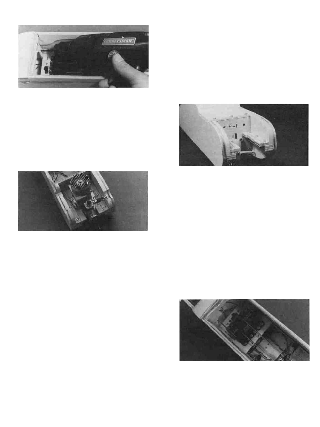
D 29. Use a drill with a 1/8" bit to drill holes through
F-2 for the throttle and nose gear pushrods.
D 30. Bend one of the pushrod wires that has a clevis
attached so it runs freely from the throttle arm on
your engine to the throttle servo.
D 31. Turn on your transmitter and receiver, and
push the throttle stick and the throttle trim tab (left
side of the transmitter) fully forward. Now turn off
the receiver and transmitter (in that order). The servo
arm should now be angled forward about halfway.
D 32. Insert the throttle pushrod through the holes
in F-l and F-2 and attach the nylon clevis to the
throttle arm on your engine.
B-Moving the Z-bend to a different hole in the
servo arm (outer hole gives more movement than
the inner hole).
C- Turning the nylon clevis on the pushrod.
D 36. Re-mount the nose gear bearing, steering arm
and the nose gear.
D 37. Take the final pushrod wire, attach a clevis
and bend the wire to match the nose gear pushrod
drawing on the fuse plan side view, but do not make
the Z-bend yet and do not cut off the excess wire.
D 38. Insert the pushrod through the holes in F-2
and F-l with the clevis at the servo end. Attach the
clevis to the servo wheel.
D 39. With the nose gear centered (not turning right
or left), mark the location of the hole in the steering
arm on the pushrod using an indelible marker.
D 33. With the pushrod in place and the carburetor
wide open, mark the location of the servo arm hole
on the pushrod using an indelible marker.
D 34. Remove the throttle pushrod and make a Zbend at the mark you just drew and cut off the excess
wire. Note: To re-insert the throttle pushrod, you will
have to remove the clevis and slide the pushrod in
from the rear. Do so now.
D 35. Turn on the radio and check the operation of
the throttle. With the throttle stick and trim fully
forward the carburetor should be fully open. With
the throttle stick fully back and the trim fully forward
the carburetor should be open just a very small
amount. With the throttle stick and the trim fully
back the carburetor should be fully closed. The servo
must not bind or "buzz" at the full- forward or fullback positions.
Note: Adjustments made in this set-up are
made by:
A-Moving the clevis to a different hole in the
throttle arm (outer hole gives less movement than
inner hole)
Note: The nose gear pushrod attaches to the
servo wheel on the opposite side of the rudder push
rod attachment.
D 40. Remove the nosegear pushrod and make a
Z-bend at the mark you just made. Cut off the excess
wire.
D 41. Remove the clevis and re-insert the nose gear
pushrod through F-l and F-2. Re-install the clevis,
hook it up and check for proper operation.
Note:To attach the Z-Bend to the steering arm,
you must remove the arm from the nose gear first.
Attach the Z-Bend and then put the steering arm
back in place. Adjustments to re-center the nose
wheel are made by turning the clevis at the servo
end of the pushrod.
If you built Wing A, skip to the next section.
D 42. Temporarily tape the aileron servo mount in
place on the bottom of the wing.
28
Page 29

D 43. Find the two small white nylon aileron clevis
connectors and screw them about halfway onto the
threaded aileron torque rods.
D 44. Screw the two white nylon clevises onto the
threaded pushrod wires that do not have clevises
attached. Screw them on 12 turns, which is halfway.
D 45. Bend the aileron pushrods to match the patterns shown in the "BOTTOM OF WING" detail on
the wing plan.
D 46. Attach the nylon clevises to the clevis connectors.
SPECIAL NOTE: To insure adequate roll
(aileron) control at low speeds, it is necessary to set
up the aileron pushrod linkage so the ailerons move
upward a lot more than downward. This is called
"differential throw". If you study the "BOTTOM
OF WING" details you will see how this is accomplished. You must use a large servo wheel, and
attach the pushrods off-center, as shown in the drawing.
D 47. Drill two 5/64" holes in your large servo wheel,
about 45 degrees off- center. The Futaba large servo
wheel has lines that radiate out from the center every
45 degrees.
D 48. With the servo wheel and the ailerons centered, hold the aileron pushrods in place over the
holes in the servo wheel, and mark the hole locations
on the pushrods using an indelible marker.
D 49. Remove the pushrods and make Z-bends at
the marks you just made.
BALANCE THE AIRPLANE LATERALLY
SPECIAL NOTE: Do not confuse this procedure with "checking the C.G." or "balancing
the airplane fore and aft". That very important
step will be covered later in the manual.
Now that you have the basic airframe nearly
completed, this is a good time to balance the airplane
laterally (side-to-side). Here is how to do it:
D 1. Temporarily insert the wing hold down dowels
into the fuselage, and attach the wing with about
four #64 rubber bands.
D 2. Start with the fuselage resting on a level table
with the nose gear off one edge of the table.
D 3. Grasp the propeller shaft of the engine and
lift, so the airplane is being supported only by the
propeller shaft and the bottom of the rudder. Do this
several times.
D 4. If one wing tip always drops when you lift, it
means that side is heavy. Balance the airplane by
adding weight to the inside edge of the other wing
tip rib. A good way to add weight to the tip is by
sticking several small nails (brads) or tacks into the
tip rib, from the inside. Add only a few nails or tacks
at a time, securing each one with a drop of thin CA
then re-checking the balance.
Note: In preparation for the next part, remove
all pushrods, all radio equipment (excepting the
switch), nose gear bearing, nylon aileron clevis connectors, nylon rudder and elevator horns, engine, rudder, elevator, ailerons and all hinges. Before removing, you may wish to pre-mark any parts that may
cause confusion when re-assembling them later.
ADD THE FUSELAGE TOP
D 1. With your T-bar and 100 grit sandpaper, sand
the top of the fuse sides, upper lockplates and the
formers smooth and flat.
D 50. Re-install the aileron pushrods, work the Zbends into the servo wheel, hook up the aileron servo
to the receiver using the aileron extension cord
provided with your radio system, and check the operation of the ailerons.
D 2. Lay the pre- shaped 1/8" balsa fuse top in
place against the front of the stab. The front edge of
the fuse top must be even with the front edge of F-3.
If not, cut or sand a small amount off the rear edge
of the fuse top. Continue cutting and checking until
the fuse top is the correct length.
D 3. Mix up some 5 minute epoxy and apply it to
the tops of F-4 and F-5 only. Immediately lay the
fuse top in place and apply thin CA glue all around
29 the edges.
Page 30

SAND THE FUSELAGE
NOTE ON COVERING TOOLS:
D 1. Use your T-bar with 100 grit sandpaper to
sand the entire fuselage smooth. Pay special attention to the glue joints, as they will show right through
the covering if left bumpy or uneven. Round all edges
slightly, excepting the wing saddle area and the
hatch saddle area, to make it pleasing to the eye.
D 2. Now change to a T-bar with 220 grit sandpaper
and go over the entire fuselage again, final sanding
it very smooth.
FUELPROOF THE ENGINE AND FUEL
TANK COMPARTMENTS
Note: Most of the model's surfaces will be sea-
led and protected by the covering material you use;
however, the engine and tank compartments would
be difficult and impractical to cover, so you must protect these areas by brushing on one or more coats of
"fuel proof paint which is available from your local
hobby dealer. Or, instead of paint, you may mix up
some 30 minute epoxy, thin it to a brushing consistency by adding a little rubbing alcohol and brush
it
on.
D 1. Fuelproof the inside surfaces of the engine
compartment, including the engine beams, balsa
triplers, and the front of F-l.
D 2. Fuelproof the breakaway plates.
D 3. Fuelproof the inside of the fuel tank compart-
ment, including the bottom of the hatch.
PREPARE THE MODEL FOR COVERING
D 1. Check the fuselage and the wing for any dents
you might have put in the wood. A small amount of
water placed on the dings will repair them. The water
causes the balsa to swell, removing the dings automatically. Use balsa filler on larger dings. Sand
the balsa filler to a smooth finish using fine grade
sandpaper. You should have already final sanded your
PT40 but give it another sanding with fine paper.
The better the finish at this stage the better the
covering will look.
D 2. Wipe all the dust from the model with a tack
rag or vacuum with a hand held attachment. Tack
rags are sold at hardware stores and are chemically
treated so they will clean surfaces prior to painting.
D 3. Make sure all hardware, engine etc. is out of
the model so you can do a good job of covering.
30
Since we recommend that you use a plastic covering such as Super Monokote to finish your PT40,
you'll need to be aware of the tools you'll need to
borrow or buy to apply the covering to the model.
The covering itself has an adhesive on the side that
goes toward the wood. The covering is heated so it
will stick to the wood. A sealing iron and a heat gun
were made expressly for applying this type of covering. You'll also need an X-Acto knife with a new blade
or scissors to cut the covering.
NOTE ON COVERING SEQUENCE:
We recommend that you start with the stab
bottom and then do the stab top, fin, elevator, rudder,
ailerons (if you built Wing B), the fuselage and then
the wing.
GENERAL COMMENTS
Pieces of covering are cut about an inch oversize. The covering is laid into position on the bottom
of the part, such as the stab, after the backing is
removed. The covering is tacked (touched with the
sealing iron) in a few places along the edges, then is
sealed along the edges with the sealing iron, leaving
a small opening at one edge for a vent. Then the
sealing iron is placed over the rest of the covering in
from the edges, heating it. Quickly seal the area with
a small rag by lightly rubbing the area. Then seal
the vent you left open. If you get any bubbles, pick
them with a pin and reseal. Now seal the covering
around any edges and trim with your knife without
cutting into the wood. The top of the part is then
covered, overlapping the edges and trimmed underneath so you won't see the seam when the plane is
on the ground. Using this covering and these tools
is not really difficult but takes some practice to get
really nice results. So practice and you'll be pleased
how nice your models will look.
COVER THE STABILIZER
D 4. Start at the corner of the fuselage. Fold 1/4
inch of the covering up against the fuse side and
anchor it in place with your sealing iron. Then tack
and fasten the rest of the covering. You want to have
a good seal at the stab/fuselage joint so oil from the
engine exhaust won't soak into the wood.
COVER THE FIN, RUDDER AND
ELEVATOR
D 5. Use the techniques mentioned above and cover
these parts. The seal at the fin/fuselage joint is impor-
tant, so seal it well.
COVER THE FUSELAGE
D 6. Start at the bottom. The bottom covering
should overlap the sides by 1/4 inch. Lay the covering
in position, tack and seal the edges. Leave the tail
and nose open slightly for trapped air to escape. Now
use the heat gun and rag and fasten the rest of the
covering.
Page 31

D 7. Do the sides next. Tack and seal the edges,
vent at the nose and tail and finish the job. Trim the
covering flush with the bottom and flush at the top
also.
D 8. Cover the top of the fuselage. Do this in two
parts, the rear and the front of the fuselage on either
side of the wing saddle area. Tack and seal the edges.
Finish the top area with the heat gun and rag. Bring
the top covering down 1/4 inch over the sides. Trim
and seal it.
D 9. Carefully cut away the covering from the fuse
sides where the wing hold down dowels will be inserted. Smear 5-minute epoxy on the dowels and insert them so they stick out the same on both sides.
Wipe off the excess epoxy with a tissue. After the
epoxy sets you may either cover or paint the exposed
ends of the dowels.
COVER THE WING
D 10. Cover the tips first with 3" x 12" pieces of
covering material. Iron the covering down to the flat
ends of the tips, then pull and stretch the covering
around the comers while heating with the iron. Trim
off the excess.
D 11. Now cover the bottom of one wing panel, overlapping the center of the wing by at least 1/4". First
iron the covering down to the center of the wing and
at the tip. Next, seal the covering to the trailing edge
and the leading edge (the covering should wrap at
least halfway around the leading edge). Once sealed
all the way around, you may shrink the covering tight
with a heat gun. Hold the heat gun a few inches away
from the covering, and keeping it moving, so you
don't melt through. Finally, use the iron to seal the
covering to the spars.
D 12. Cover the bottom of the other wing panel in
the same manner as above.
SPECIAL NOTE: When covering the top of
the wing, make sure the top covering overlaps the
bottom covering by at least 1/4" at the leading edge.
D 13. Next, cover the top of one of the wing panels.
At the center of the wing, allow the covering to overlap the center ribs by about 1/2" . Slit the covering
at the spars, then iron it down to the side of the
center rib, as shown in the following photograph.
D 14. Cover the top of the other wing panel making
sure you overlap the covering at least 1/2" at the
center.
SPECIAL NOTE: The above instructions for
covering told you how to cover with one color. You
can get a little fancier and use a second color for trim
like we did on ours on the box lid. If you use two
colors, cover with the lightest color first, like the
white on ours. The white was put on the fuselage
side about halfway down. Then the red was cut with
a straight edge, tacked and sealed at the red/white
seam and then tacked and sealed at the bottom. A
heat gun was then used to finish. The rest of the
plane was covered totally in white and then pieces
of Super MonoKote red were cut to shape and adhered
with a heat gun and rag to the white. Just the top
of the wings have the red trim. You usually want the
top of the wings to look different than the bottom so
you can tell what the airplane is doing in the air.
After the red trim was added, we put
some of our 1/16" black striping tape along the red
for more trim. We used gray Super MonoKote for the
windows, masked them off and spray painted black
around the edges to give the windows some depth.
You can follow our trim scheme or create your own!
Use your imagination and have fun creating your
very own PT40.
ADD "WASHOUT" AT THE WING TIPS
SPECIAL NOTE: One important flying
characteristic of the PT40 is its ability to recover
"hands-off" from a steeply banked turn. This is made
possible by building the wing with DIHEDRAL and
WASHOUT. You will add washout to each wingtip
by intentionally warping the wing panels, so that
the trailing edge will be higher than the leading
edge at each wingtip. Here's how to do it...
31
Page 32

D 1 Have someone hold the center of the wing
firmly down to the flat building surface Now grasp
the tip of the wing and twist it so that the trailing
edge raises off the surface While holding in this
twist, use a heat gun to "re-shrink" the covering.
Heat both the top and the bottom When you let go
of the tip, you will see that the wing will retain some
of the twist.
D 2. You must continue twisting and re-shrinking
until the trailing edge is 7/8" off the surface AT
BOTH TIPS As an aid in getting this height correct,
you may make a small wood block 7/8" high by gluing
together pieces of scrap wood Keep this block handy
while twisting and heating, to check your progress.
D 3. Depending on what type of covering you have
used, you may find that, in time, some of the washout
may disappear Check it after an hour and repeat the
above process if necessary Also, re- check it periodically before you go flying, because THIS IS A VERY
IMPORTANT REASON FOR THE STABILITY OF
YOUR PT40
D FINAL ASSEMBLY
D 1 Lay the rudder and elevator (and ailerons if
you built Wing B) on the plans and mark the hinge
locations on the leading edge of each part Now use
your X-Acto knife (blade must be sharp) to cut slits
in the covering at the hinge locations Trial fit the
hinges to make sure you have "found" the slots which
you previously cut
L] 2. Glue the hinges into the rudder and elevator
(and ailerons) NOTE Do not just smear glue on the
hinge and push it into the slot, as most of the glue
will be wiped off as it is being pushed in You must
also work some glue into the slot A good way of doing
this is to scoop up some epoxy with a plastic soda
straw, then pinch the end of the straw, insert it into
the hinge slot, and squeeze the straw to force glue
into the slot Then insert the hinge hallway into the
slot After pushing in the hinge, wipe away all excess
glue with a tissue.
D 3. After the epoxy has hardened, put glue (15 or
30 minute
epoxy
is
recommended) into
the hinge slots
in the stab, and push the elevator hinges into the
slots Wipe away all excess epoxy with a tissue. Re-
peat this process for the rudder
D 4 Wing B only Glue the aileron hinges in place
in the same manner, but also apply epoxy into the
torque rod holes before pushing the ailerons into
place.
D 5. Install 1/4" wide wing seating tape (sticky
side down) onto the wing saddle and the top of the
F-2A (or F-2B) saddles
D 6 Note- Each time you put the wing into the
wing saddle to fly the model, it needs to be in the
same position Follow the steps below so the wing
will be in the correct relationship to the fuselage.
A Place the fuselage on the work surface right
side up Place the wing into the wing saddle Make
the following measurements If the distances you
measure are not the same, move the wing in the wing
saddle until the measurements are the same.
B Measure the wing from side to side in the
saddle The distance from the fuselage side to the
wing
tip
on each side should be
C Measure from each wing tip to each stab tip.
These
distances should be
D Wing tip to work surface distance is the same
on both sides C = C
E When the wing is all lined up to the fuselage
after the above measurements are made, mark a
small line on the wing and a small line on the fuselage drawn with a pen on the covering, so you can
put the wing in the same position each time before
you rubber band it.
D 7. Re-install the nose gear assembly, main landing gear, engine and muffler.
D 8 Re- install the nylon horns on the elevator
and rudder For the rudder, you will have to re-drill
the two holes for the 2-56 screws because the lower
hinge now blocks the holes.
D 9 WING B ONLY- Using a sharp X-Acto knife
or single edge razor blade, carefully cut away the
covering from the bottom of the wing where the aileron servo mount will be attached You should be able
to faintly see the dark outline that you previously
drew under the covering Now glue the aileron servo
mount to the bottom of the wing.
D 10. Using an X-Acto knife, cut away the covering
from the rudder, elevator and nose gear pushrod slots;
then re-install the pushrods for the rudder, elevator,
throttle, nose gear and (ailerons).
32
the
the
same. B =
same. A =
B
A
Page 33

D 11. Cut a hole in the center of the fuse top, about
2" behind the wing saddle, and glue in a 2-1/2" length
of fuel tubing to serve as an antenna exit (see the
fuse plan).
D 12. Wrap foam rubber around the receiver and
hold the foam in place with a couple of rubber bands.
Now you must attach the receiver to the fuselage in
such a way that it does not move around, but at the
same time it must be cushioned from vibration. A
good method for accomplishing this is to secure two
hooks down in the bottom corners of the fuselage,
and rubber band the receiver down.
RECEIVER (AND
BATTERY) MOUNTING
-BASSWOOD BLOCK BOTTOM
(SCRAP FROM WING SPAR)
D 13. Wrap the battery pack in foam rubber, place
it in a plastic bag, and close it with a couple of small
rubber bands. Now secure the battery pack in the
bottom of the fuel tank compartment in the same
manner as you did the receiver. Also place a piece of
foam rubber between F-l and the battery pack.
D 14. From scraps of plastic, make the "antenna st-
rain relief and the "antenna clip" (unless your radio
system includes these). Pass the receiver antenna
wire through the holes in the plastic strain relief
piece, then through the antenna exit tube. Adjust
the position of the strain relief such that the portion
of the antenna inside the fuselage remains loose,
even when you pull on the end of the antenna. Now
attach the end of the antenna to the top of the fin
using your antenna clip, a small rubber band and a
pin. Note: The receiver antenna is "tuned" for the
frequency on which the radio will operate, so do not
cut off any of its length. Just allow the excess to trail
behind.
D 15. Plug the servo wires into the receiver and hook
up the battery and switch (refer to your radio instruc-
tion manual for guidance).
D 16. The fuse top view shows a piece of 1/16" wire
passing through the switch and out the side of the
fuse. This enables you to switch the receiver on and
off without removing the wing. Install a remote on/off
switch pushrod similar to the one shown.
D 17. Lay the fuel tank in place on top of the battery
pack. Run a piece of fuel line tubing from the fuel
pick-up ("klunk") through the hole in F-l to the fit-
ting on the carburetor. Run a second piece of tubing
from the tank "vent" through the hole in F-l to the
pressure tap fitting on the muffler. To prevent fuel
foaming the tank must be isolated from direct contact with the fuselage, so add foam rubber in front
and on top of the tank before replacing the hatch.
D 18. Install the wheels on the main landing gear
and nose gear using 5/32" wheel collars on both sides
of each wheel
SPECIAL NOTE: If you plan to fly from a
concrete, blacktop or smooth grass field, use 2-1/2"
diameter main wheels and a 2-1/4" diameter nose
wheel. However, if the field you will be flying from
is rough or has fairly long grass, we recommend using
2-3/4" main wheels and a 2-1/2" nose wheel. In either
case, you should bend the main landing gear if necessary so the model sits level or slightly nose down
when at rest.
D 19. Install the proper size propeller for your engine
(see your engine instruction manual), and a 2-1/4"
diameter spinner. Note: If you choose not to use a
spinner, you should ( for safety reasons) use a rounded
"acorn"-type prop nut to hold the propeller on.
SPECIAL NOTES ON PROPELLERS: Vibration is the main enemy of the electronic and
mechanical parts in an R/C airplane, and an out-ofbalance propeller is the primary source of the hard
vibrations that cause problems. For only a few dollars
you may purchase a prop balancer. We highly recommend that you do so, and carefully balance each propeller before bolting it on your airplane.
Always use propellers that are in perfect shape.
Discard any prop with nicks, scratches, splits or
cracks or any sign of wear and damage. Never repair
or alter a prop (propeller).
Paint the prop tips white so you can see the
ends when the prop is spinning (this is especially
important if you are using one of the black fiberglassfilled nylon props).
Install the prop with the curved side facing
forward. Securely tighten the prop nut. Inspect the
prop and re-tighten the nut after every few flights.
If you install a spinner, make sure the edges of the
spinner do not touch the prop blades.
D 20. While standing behind the model, adjust
the servo reversing switches on your transmitter so
the elevator, rudder, throttle (and ailerons) move in
the correct directions as follows:
33
Page 34

given below, with full movement of the transmitter
sticks.
ELEVATOR = 3/16" up and 3/16" down
RUDDER = 3/16" right and 3/16" left
AILERONS = 7/16" up and 1/8" to 1/4" down
D 23 Write your name and address plainly on a
piece of paper and glue the paper inside the fuselage
onto one of the fuse sides If you lose your model the
finder will know who to contact
D 24. Temporarily attach the wing with 10 or 12
good #64 rubber bands
REMEMBER Proper installation of all R/C
components and accessories is crucial to the safe and
proper operation of your model, and that improper
or faulty installation of even one component or accessory may result in damage or destruction of the entire
model, as well as cause serious personal injury or
property damage Therefore, if you are confused or
uncertain about any of the above final assembly
steps, please ask an experienced model builder for
assistance
BALANCE YOUR MODEL
D 21 By turning the clevises on the threaded ends
of the pushrods, adjust the elevator and rudder to
the neutral (not up or down) positions Also (for Wing
B) adjust the aileron pushrod clevises so the bottom
of the ailerons are even with the flat bottom of the
wing
NOTE: THIS STEP IS VERY IMPORTANT,
AND MUST NOT BE OMITTED!
D 1 With the wing rubber banded to the fuselage,
all parts of the model installed, and an empty fuel
tank, gently turn the model upside down.
D 2 By feel, determine the location of the center
of the main wing spar in the vicinity of the 2nd wing
rib (where the bottom center section balsa sheeting
ends).
D 3 From the center of the main wing spar, measure
exactly 5/8" back (toward the tail) and make a mark
Do this on both sides of the wing bottom Note For
ease of checking the balance, you may stick a
thumbtack into the bottom wing sheeting at these
balance point marks.
D 4 Turn the fuselage right side up, place your
index fingers under the wing and lift the airplane
at the balance point If the tail drops when you lift,
the model is "tail heavy ' and you must glue weights
into the nose of the model, either in the engine area
or fuel tank compartment until it balances right on
the balance point On the other hand, if the nose of
the model drops when lifting, the model is "nose
heavy" and you must glue a small amount of weight
to the tail (under the stab, near the fuse) until it
balances right on the balance point
FLYING
Note The throttle pushrod should already be
properly adjusted according to "PUSHRODS", Step
35
D 22 Adjust the pushrod hookups so the elevator,
rudder (and ailerons) move the correct amounts, as 34
IMPORTANT: Regardless who you are or
where you live, we strongly urge you to seek the
assistance of a competent, experienced R/C pilot to
check your model for airworthiness AND to teach you
how to fly No matter how stable or "forgiving" your
Page 35

model is, attempting to learn to fly on your own is
dangerous and may result in serious or even fatal
injury to yourself and others, and total destruction
of your model Therefore, find an instructor (even if
it means driving a long distance) and fly only under
his or her guidance and supervision until you have
acquired the skill necessary for safe and fully controlled operation of your model
CHARGE THE BATTERIES
Follow the battery charging procedures in your
radio instruction manual You should always charge
your transmitter and receiver batteries the night be-
fore you go flying, and at other times as recommended
by the radio manufacturer
1. FLY IN A SAFE PLACE
1. The best place to fly your R/C model is an AMA
chartered club field Ask your hobby shop dealer if
there is such a club and join Club fields are set up
for R/C flying which usually makes your outing more
enjoyable The AMA can also tell you the name of a
club in your area We recommend that you join AMA
and a local club so you can have a safe place to fly
and also have insurance to cover you in case of a
flying accident
If a club and its flying site are not available,
you need to find a large, grassy area at least 6 miles
away from any other forms of radio operation like
boats and cars and also is away from houses, buildings and
streets A school
yard
may
look
inviting
it is too close to people, power lines and possible radio
interference
2. RANGE CHECK YOUR RADIO
Wherever you do fly, you need to check the operation of the radio every time you fly This means
with the antenna down, and the receiver and transmitter on, you should be able to walk 100 feet away
from the model and still have control Have someone
help you Have them stand by your model and while
you work the controls, tell you what the various control surfaces are doing If the control surfaces are not
acting correctly, do not fly Correct the problem first.
3. GROUND CHECK THE MODEL
The instructor will check to see that you have
the radio installed correctly and that all the control
surfaces do what they are supposed to He/she will
check the engine operation and help you "break in"
the engine on the ground This means that you will
run the engine and use up at least two tanks of fuel
to let the engine get broken in Adjustments are made
to the carburetor so the engine runs at its best The
instructions that come with the engine will tell you
how to break in the engine
ENGINE SAFETY PRECAUTIONS
Note Failure to follow these safety precautions
may result in severe injury to yourself and others.
but
Keep all engine fuel in a safe place, away from
high heat, sparks or flames as fuel is very flammable.
Do not smoke near the engine or fuel, remember that
the engine exhaust gives off a great deal of deadly
carbon monoxide Therefore do not run the engine in
a closed room or garage.
Get help from an experienced pilot when learning to operate engines
Use safety glasses when starting or running
engines.
Do not run the engine in an area of loose gravel
or sand, the propeller may throw such material in
your face or eyes.
Keep your face and body as well as all spectators
away from the path of the propeller as you start and
run the engine
Keep away from the prop loose clothing, shirt
sleeves, ties, scarfs, or loose objects (pencils, screw
drivers) that may fall out of shirt or jacket pockets
into prop.
Use a "chicken stick" device or electric starter,
follow instructions supplied with the starter or stick
Make certain glow plug clip or connector is secure
so that it will not pop off or otherwise get into running
propeller
Make all engine adjustments from behind rotat-
ing propeller.
The engine gets hot! Do not touch it during or
after operation Make sure fuel lines are in good condition so fuel is not leaked onto a hot engine causing
a fire
To stop engine, cut off the fuel supply by closing
off the fuel line or follow the engine manufacturer's
recommendations Do not use hands, fingers or any
body part to try to stop the engine Do not throw
anything into the prop of a running engine
The instructor will usually tell you about flying
rules at the field The number one rule you should
always adhere to is -Do not turn on your radio system
before you first check out what frequencies people
are using at the time If you turn on your radio system
while someone is flying on your frequency, you could
crash their airplane This is called "shooting someone
down" No one wants all their hard work ruined because someone wasn't thinking and turned on their
transmitter at the wrong time. Always try to remember this rule
The instructor will check the model over to
make sure all the screws are tight and that the prop
is tight He/she will check hinges to see if they are
securely glued The instructor therefore checks all
parts of the model to see if it is airworthy The instructor will recommend changes to be made before the
model is ready for flight.
35
Page 36

4. TRIM OUT THE MODEL
Trimming the model means that you have an
experienced flier fly the model and make final adjustments to the amount of throw in the control surfaces
The distances for the control surface throws we gave
you previously are close to where they should be
But you won't really know until the plane is in the
air Slight changes need to be made The experienced
flier, usually an instructor from a local club, will
know what to change as he or she flies the model
The instructor will adjust the trim levers on the radio
transmitter to make the model fly straight and level
with the control sticks in neutral Then when the
plane is on the ground he or she will adjust the
clevises at the rudder, elevator and ailerons so the
trim levers can be moved back to neutral (As you
become more experienced, you can trim out your new
models yourself The first flight for any new plane
should be used to trim out the model) Trim changes
may be needed anytime so keep checking to see how
the control surfaces react to the stick movements.
5 LEARNING TO HANDLE THE MODEL ON THE
GROUND
After your instructor makes sure the model is
airworthy, it's your turn' The first thing you do is to
practice taxiing the model on the runway Choose a
time when there is very little wind to blow the model
over on the ground Work the controls with a gentle
hand Don't push the sticks way over as far as they
go Give small amounts of right or left rudder to keep
the model heading straight down the runway As the
model heads away from you, pushing the rudder stick
to the right makes the model turn to the right and
pushing the stick to the left makes the model turn
to the left Now turn the model around, slowly' Too
fast and you could tip it over Now as the model comes
toward you, pushing the rudder stick to the right
makes the model turn left' The model is actually still
turning right but it looks backwards to you because
the model is coming at you now This is normal You
may want to turn your back on the model and look
over your shoulder as you are learning to taxi.
Keep practicing the taxi on the runway, keeping
the model in control at all times After awhile, look
straight at the model as it comes toward you without
turning your back on it Push the stick in the direction
that the model is turning to make it turn the other
way Practice until you feel comfortable making the
model turn right and left and making it turn around
and come back to you Set up some empty pop cans
or something similar and practice going around the
cans without knocking them over
6. YOUR FIRST FLIGHT
The ideal way to leam to fly is to use the buddy
box system The instructor has his or her transmitter
attached to yours by a cord There is a switch on the
instructor's transmitter so he/she can control who is
flying the model If you get into trouble, the instructor can switch the control back to him/her and get
the model flying safely again The instructor will
take the plane up to a safe altitude and then let you
take over to practice for 2 or 3 minutes Then the
instructor can land the model for you As you progress, you then learn to land the plane and take it off
by yourself and then to do a complete solo'
If it is absolutely necessary for you to learn
by yourself, go to your hobby shop and buy some
books on flying models Learn all you can before you
actually take the plane up Take your time and don't
try to do everything at once You'll have to take the
plane off, do some turns and then land it again without crashing it Have a flight plan in mind before
you take off Following is a sample flight plan you
might want to follow for those first critical flights
Study this flight plan and run through it on the
ground Practice moving the controls on your transmitter and imagine what the plane is doing The
more you practice on the ground, the easier it will
be in
the
air
Read and abide by the following Academy of
Model Aeronautics Official Safety Code:
GENERAL
1 I will not fly my model aircraft in competition or
in the presence of spectators until it has been proven
to be airworthy by having been previously successfully flight tested.
2 I will not fly my model aircraft higher than approximately 400 feet within 3 miles of an airport without
notifying the airport operator I will give right of way
to, and avoid flying in the proximity of full scale
aircraft Where necessary an observer shall be
utilized to supervise flying to avoid having models
fly in the proximity of full scale aircraft
3 Where established, I will abide by the safety rules
for the flying site I use, and I will not willfully and
deliberately fly my models in a careless, reckless and/
or dangerous manner
RADIO CONTROL
1. I will have completed a successful radio equipment
ground check before the first flight of a new or repaired model
2 I will not fly my model aircraft in the presence of
spectators until I become a qualified flyer, unless
assisted by an experienced helper
3 I will perform my initial turn after takeoff away
from the pit, spectator and parking areas, and I will
not thereafter perform maneuvers, flights of any sort
or landing approaches over a pit, spectator or parking
area.
36
Page 37

SAMPLE FLIGHT PLAN
'LEFT
5 LEFT
DOWNWIND
TAKEOFF-GENTLE CLIMB
RUNWAY
LEFT
LEFT
/RIGHT
DOWNWARD
GLIDE
1 Head the model into the wind Release the model
and slowly advance the engine to full throttle
2 Make gentle right or left stick movements to correct
the take off run and make the model run straight
down the runway
3 As the speed builds up, give a slight amount of
"up elevator", pulling back on the elevator stick, and
the plane will fly itself off the ground Don't give too
much up elevator You don't want the nose to rise so
the model climbs too steeply
4 Reduce the throttle slightly to give a nice gentle
rate of climb Keep the wings level with right and
left rudder with Wing A or right and left ailerons
with Wing B Fly the plane to about 100 to 150 feet
Don't fly it so far away that you can't see it
5 Make a wide, gentle turn to the left by giving left
rudder or left aileron stick Keep turning until the
model is heading downwind, which is back toward
you Level the wings by centering the stick You may
have to give a little opposite stick to level it out
6 After the model passes you, start a very gentle left
turn Level it out and now do 2 or 3 figure eights,
which are a series of right and left turns
7 After the last figure eight left turn, keep the plane
flying upwind for a ways and then prepare for your
landing Make a gentle left turn and fly downwind
past where you are as far as you flew upwind
8 Make a gentle left turn and fly upwind and start
to judge where you want to land
9 Line the plane up with the runway Don't worry
too much if you don't land on the runway the first
time Just getting the plane down in one piece is
your primary goal
10 When you are sure you can reach the runway, cut
the throttle slowly to give the plane a gentle downward glide, not too steep Keep the wings level Don't
bring the nose up too much as the plane may stall
(the wings will lose their lift and the plane will tend
to drop and go out of control)
11 If you are going to land short of the runway, give
a little power to bring it in If you are overshooting
the runway and the plane is low enough and you
have room in the grass, land it If you are too high,
give it throttle, a little up elevator, get back into the
pattern and come around again for another try
37
After the model is on the ground after that first
flight, you can stand back and say "I did it'" even
though the pattern you flew may not have been perfect and the plane didn't do what you wanted it to
do Hopefully, you got the model down in one piece
Turn off the transmitter and then the receiver Check
out the model Is the prop still ok All the screws
tight
Any
dings in
the
covering
Always
check
the
plane after each flight Fix any problems on the
ground They sure won't get fixed in the air
Make the model airworthy again, fuel it up and
take her up again Try flying the pattern again and
again until you feel comfortable Then try flying a
pattern you make up.
Remember, practice and practice You will have
a few setbacks, we all do when learning Just don't
give up and have fun while you leam Radio Control
model airplane flying is one of the most rewarding
hobbies around It just takes a little work and practice
to get there
CHANGING FROM 3 TO 4 CHANNEL
VERSION
If you have constructed Wing A and set up your
PT40 for 3-channel operation, it will serve you well
during the initial training phase of learning to fly
R/C After you have become proficient at soloing your
3 channel PT40 (which may require 50 to several
hundred flights), you will then be ready to fly a more
maneuverable airplane with 4 channels of control
(including ailerons)
Assuming your PT40 is still in good condition,
you may wish to convert it to a 4-channel version
The best way to do so is to purchase a new PT40
wing kit and build it up following the wing B instructions
Or: You may carefully cut the tapered trailing
edge off your wing and use it along with the aileron
torque rod hardware to make ailerons for your wing,
following the wing B instructions Note that this will
produce a wing that has ailerons and the full dihedral
of Wing A We think you will find the results to be
satisfactory
Or: You may cut the wing in half down the
center joint, cut away the covering in the center rib
bays, re- join the wing halves at the Wing B dihedral
angle, gluing in the plywood dihedral braces
found in the die-cut "B" sheet, cut off the tapered
trailing edge and use it along with the aileron torque
rod hardware to make ailerons for your wing follow-
ing the Wing B instructions Then re-cover the center
of the wing Although this method produces a true
"Wing B", it is the most difficult, so we urge you to
seek the help of an experienced modeler.
KEEP MODEL AVIATION A SAFE SPORT!
GOOD LUCK AND GREAT FLYING!
Page 38

FLIGHT PROBLEMS
TROUBLE SHOOTING GUIDE
FLIGHT PROBLEM PROBABLE CAUSE
Does not automatically pull out of a
dive after elevator stick is released
Does not automatically return to
straight flight after a right or a left
bank after rudder stick is released
1 If dive continues straight ahead, the
cause may be incorrect elevator trim (a)
or improper balance (b).
2. If dive results in a right or left
turning spiral, the cause may be
incorrect elevator and/or rudder
trim.
1. Incorrect rudder trim.
2. If rudder trim varies as speed is
changed, the cause may be incorrectly
aligned or warped vertical fin.
3. The airplane may not be laterally
(side-to-side)) balanced.
RECOMMENDED SOLUTIONS
1 (a) Re-trim the elevator for level flight
at 1/2 throttle.
1 (b).Carefully balance the airplane, front
to back at the balance point shown on the
plan, 5/8" behind the center of the main
spar.
2. Re-trim the rudder and elevator for
straight and level flight at 1/2 throttle.
If this does not correct the problem, see
below.
1. Re-trim the rudder for straight flight
at all speeds.
2. Check alignment of vertical fin. If
warped, twist while heating. If not
aligned with fuselage centerline, cut off
and re-install.
3. Check lateral balance by lifting the
airplane at the propeller shaft and at the
aft end of the fuselage If one side drops,
add weight to the opposite wing tip to
balance.
Operating elevator and rudder control
stick results in jerky and erratic flight.
4. The wing may be crooked in the
saddle.
5. Unequal or insufficient washout
(twist) in the wing panels.
1. Improper control surface throws.
2. Insufficient or weak wing hold down
rubber bands may allow the wing to lift
when making a tight turn or when
pulling out of a dive.
3. If the model is balanced more than
1/4" behind the recommended location, it
will be too pitch sensitive and "squirrely".
4. Check wing alignment by
measuring from both wing tips to
the top of the rudder hinge line
These measurements must be the same,
within 1/16" If not, re-position the
wing in the saddle.
5. With the wing on a flat surface, check
the amount of washout at each tip. The
washout must be the same at both tips
(7/8").
1. Set up the elevator and rudder to move
the recommended amounts with full
deflection of the transmitter stick.
2. Attach wing to fuselage with at least
10 or 12 good #64 rubber bands.
3. Carefully balance the airplane,
front-to-back, at the balance point shown
on the plan, 5/8" behind the center of
the main spar.
38
Page 39

GLOSSARY
AILERON: The hinged, movable surfaces on the trailing edge of the wing
that causes the aircraft to roll (bank) left or right.
BREAKAWAY PLATE: A part, usually hardwood, to which the engine is
fastened by screws. The plate will "breakaway" in the event of a crash,
thereby saving the engine from damage.
BULKHEAD: A part that gives shape to the fuselage and also divides it into
different compartments. Same as a former. Usually designated "Fl", "F2",etc.
CA (CYANOACRYLATE): A glue that cures almost instantly to give a
strong bond. Thin CA seeps into a joint to bond it and thick CA will fill gaps
at a joint.
CLEARANCE HOLE: A hole drilled or cut in a part to leave room for
another part (screw, etc.) to fit through it.
CONTROL SURFACE: The movable parts of the aircraft that control its
operation: The rudder, the elevator, and the ailerons (some planes even
have flaps and/or spoilers).
DIHEDRAL: The angle between the right and left wing panels.
DIHEDRAL BRACE: An angled part that helps to hold the wing panels at
the correct angle, and provide strength in the center of the wing.
ELEVATOR: The hinged, movable part at the rear of the stabilizer that
causes the aircraft to climb or dive.
ENGINE BEAM: A part, usually hardwood or plywood, rigidly mounted
to the fuselage that supports the engine.
EPOXY: A two part glue consisting of a "resin" and a "hardener" that
when mixed together gives a very strong glue joint. Epoxy comes in
different bonding times: 5 minute, 15 minute, 30 minute, etc.
FINAL SAND: To use a fine grade of sandpaper to sand the airplane, after
everything is built, to get it ready to be covered or painted.
FIN: The vertical stabilizer or fixed part of the tail section that helps keep
the aircraft going straight ahead.
FIREWALL: A part, usually plywood, that separates the engine compartment from the tank compartment. The engine mount or beams
are attached to the firewall.
FORMER: A part that gives shape to the fuselage and also divides it into
different compartments. Same as a bulkhead. Usually designated "F1",
"F-2",
etc.
FUSELAGE (FUSE): The body of the model.
GLUE JOINTS: The area where two or more parts are joined together by
glue.
LEADING EDGE (L.E.): The front or forward edge of a part such as the
leading edge of the wing or the leading edge of the rudder.
PILOT HOLE: A small hole that is drilled to guide a screw into the wood.
The hole is smaller than the screw diameter.
RUDDER: The hinged, moveable part at the rear of the fin that causes the
aircraft to turn left or right
SADDLE: The areas on the fuselage where the wing and the stabilizer rests.
SPAR: A part that runs the length of the wing and acts to strengthen it.
STABILIZER (STAB): The fixed horizontal part of the tail section that
helps to keep the aircraft from pitching (climbing or diving).
TACK GLUE: To glue parts together temporarily so they will stay in place
during another procedure. A very small amount of glue is used so the parts
can be broken apart later.
TACK RAG: A chemically treated rag that is used to clean dust and dirt
from the model after it has been final sanded.
TRAILING EDGE (T.E.): The rear or back edge of a part such as the
trailing edge of the wing or the trailing edge of the rudder.
TRAIL PIT: The attempt to fit parts together before you glue them to make
sure they fit correctly..
WING PLATE: A piece of thin plywood that is glued to the top of the wing
to protect it from rubber bands or wing bolts.
WING: The part of the model that creates lift. The wing can be mounted
on top of the fuselage, on the bottom of the fuselage or somewhere in
between.
Add shear webs to the wing as described below (after step 17 on page 18)
We have included in this kit, ten 3/32"
Balsa Shear Webs which are wrapped in clear
plastic. We recommend that you add them as
described below as they will add strength to the
wing which will help it survive violent manuev-
ers and crashes.
Glue a 3/32" balsa shear web to the
back side of the main 3/8" x 1/2" basswood spars
in each of the four rib bays shown in the sketch.
Also glue one shear web onto the front side of the
spars in the rib bay next to the dihedral brace.
These shear webs should be securely glued to the
spars for maximum strength and sanded flush
with the top and the bottom of the wing.
NOTICE:
DIHEDRAL BRACES
WING ROOT (CENTER)
DIHEDRAL BRACES
39
LEADING EDGE
TRAILING EDGE
SPAR
SPAR
3/32" BALSA SHEAR WEBS SHOULD
BE ADDED IN THESE FIVE PLACES
Page 40

PART NUMBER
QTY DESCRIPTION
PT40 PARTS LIST
PART NUMBER
QTY DESCRIPTION
PT40F01
PT40F02
PT40F03
PT40F05
PT40F06
PT40F07
PT40F10
PT40F15
PT40F16
PT40F17
PT40F22
PT40P01
PT40P02
PT40R01
PT40R02
PT40R03
PT40S01
PT40S02
PT40S03
PT40W05
PT40W08
PT40W09
PT40W14
PT40W15
WBNT112
PT40A02
PT40W07
2 Balsa shaped 1/8
Fuselage Side
1 Balsa Shaped 1/8
Fuselage Top
1 Balsa Shaped 1/8
Fuselage Bottom
1 3-Ply1/8DieCutF2,F3
2 3-Ply 1/8 Die Cut Fuselage
Doubler
1 3-Ply 1/8 Die Cut Fuselage
Bottom, Servo Tray
2 3-Ply 1/8 Die Cut F1, Stab
Saddle, Lockplates
1 3-Ply 1/8 Die Cut F4, F5,
F6
2 Dowels -1/4 Diameter x 25"
Pushrods
1 3-Ply 1/8x3-23/32x3-1/2
Hatch
2 Balsa Shaped 1/8 Upper
Fuselage Side
1 Plan, Fuselage and Wing
1 Instruction Book
1 Balsa Shaped 1/4 Rudder
1 Balsa Shaped 1/4 Fin Rear
1 Balsa Shaped 1/4 Fin Front
1 Balsa Shaped 1/4 Stab
Front
1 Balsa 1/4x2-3/4x20-7/8
Stab Rear
1 Balsa 1/4x1-1/4x20-7/8
Elevator
1 Balsa 1/8x3x13 Center
Sheeting
4 Basswood 3/16x3/16x30
Front Spar
2 Balsa Shaped 3/8 Wing Tip
1 3-Ply Die Cut 1/8 Dihedral
Braces
1 3-Ply Die Cut 1/8 A & B
Wing Braces, F-2A, F-2B,
Gauges, A-3, B-3
1 Wire 5/32 Main Gear
1 SUB PACK - RIBS
13 Balsa 3/32 Die Cut Rib,
2 Per sheet
PT40F14
PT40W10
PT40A05
PT40F04
PT40F09
PT40F11
PT40F12
PT40F18
PT40R04
PT40S04
PT40W11
PT40M02
NYLON26
RUBB001
WBNT111
WIRES16
PT40M01
NUTS001
NYLON02
NYLON 16
NYLON 17
NYLON20
NYLON21
NYLON30
NYLON33
SCRW002
SCRW003
SCRW004
SCRW010
SCRW020
SCRW024
WBNT110
WHCL005
WSHR002
1 7-Ply 3/8x2x3-15/32
Landing Gear Plate
2 3-Ply 1/32 x 1-1/2x3/4
Wing Plate
1 SUB PACK - BALSA
PARTS
2 Balsa Shaped 1/4 Upper
Nose Tripler
2 Balsa Shaped 1/4 Lower
Nose Tripler
1 Balsa Tapered 9/64 x 1-1/2
Tail Wedge
1 Balsa 1/8x2x3-3/4
Windshield
1 Balsa 1/2 Tri 3-15/32
Windshield Brace
2 Balsa 1/4 Tri 4-7/8 Fin/
Stab Fillet
2 Balsa 1/4x1/4x5-1/2
Stab Tips
1 Servo Rail Brace
1 HARDWARE BAG
1 Nylon Strip Hinge, 9"
6 #63 Rubber Bands
1 Wire 5/32 Nose Gear
6 Threaded Pushrod Wires
1 PARTS BAG - NYLON
AND METAL
8 4-4- Blind Nuts
2 Nylon Control Horns
1 Steering Arm
4 Nylon Standard Clevis
2 Nylon Swivel
2 Nylon Aileron Clevis
4 Nylon Landing Gear
Straps
1 Nylon Nosegear Bearing
4 2-56 x 5/8 Screws
8 4-40 x 1 Screws
8 #4x1/2 Screws
6 #4 x 5/8 Screws
1 6-32 x 3/16 Screw
3 #2 x 3/8 Screws
1 Aileron Torque Rods, 1 Set
1 5/32 Wheel Collar
4 #4 Washer
PT40A04
DOWEL021
PT40F08
PT40F13
1 SUB PACK - HARDWOOD
2 Dowel 5/16 Dia x 5-3/16
Wing Hold Down
2 3-Ply 3/8x21/32x3-1/4
Engine Beam
2 3-Ply 1/4x3/4x3-1/4
Breakaway Plate
- IMPORTANT NOTICE -
TO MAXIMIZE THE "SELF-RECOVERY" CAPABILITIES
OF THIS MODEL, TRIM THE ELEVATOR AND RUDDER
FOR STRAIGHT AND LEVEL FLIGHT AT 1/2 THROTTLE.
Beginners: Please show this notice to your instructor.
PT40W01
PT40W02
PT40WU4
PT40W06
1 WING PACK
1 Balsa Leading Edge,
Trailing Edge, Set
4 Basswood 3/8 x 1/2 x 30
Main Spar
2 Balsa Tapered 11/32 x
1-3/16 x 30 Trailing Edge
Slide the slllcone bands over the
nylon clevises to insure that they do not
pop open during flight.
 Loading...