

Page 1
INSTRUCTION MANUAL
Wingspan: 84.5 in [2140mm]
Wing Area: 1556 in
Weight: 14 – 17 lb [6350 – 7710g]
Wing Loading: 21 – 25 oz/ft2 [63 – 77g/dm2]
Length: 85 in [2160mm]
2
[100.4dm2]
WARRANTY
Great Planes® Model Manufacturing Co. guarantees this kit to be
free from defects in both material and workmanship at the date
of purchase. This warranty does not cover any component parts
damaged by use or modifi cation. In no case shall Great Planes’
liability exceed the original cost of the purchased kit. Further,
Great Planes reserves the right to change or modify this warranty
without notice.
In that Great Planes has no control over the fi nal assembly or
material used for fi nal assembly, no liability shall be assumed nor
accepted for any damage resulting from the use by the user of
the fi nal user-assembled product. By the act of using the userassembled product, the user accepts all resulting liability.
If the buyer is not prepared to accept the liability associated
with the use of this product, the buyer is advised to return
this kit immediately in new and unused condition to the place
of purchase.
Radio: 5-channel minimum computer radio with mixing
functions, eight servos
Motor/Engine: 1.60 – 2.10 cu in [26 – 34cc] two-stroke,
2.00 – 2.20 cu in [33 – 36cc] four-stroke,
2.5 – 3.0 cu in [43 –50cc] gas
RimFire
™
80-75-230 out-runner brushless motor
To make a warranty claim send the defective part or item to Hobby
Services at the address below:
Hobby Services
3002 N. Apollo Dr., Suite 1
Champaign, IL 61822 USA
Include a letter stating your name, return shipping address, as
much contact information as possible (daytime telephone n umber,
fax number, e-mail address), a detailed description of the problem
and a photocopy of the purchase receipt. Upon receipt of the
package the problem will be evaluated as quickly as possible.
READ THROUGH THIS MANUAL BEFORE STARTING CONSTRUCTION. IT CONTAINS IMPORTANT
INSTRUCTIONS AND WARNINGS CONCERNING THE ASSEMBLY AND USE OF THIS MODEL.
Entire Contents © Copyright 2008 GPMA1420MNL V1.0
Champaign, Illinois
(217) 398-8970, Ext 5
airsupport@greatplanes.com
Page 2

TABLE OF CONTENTS
INTRODUCTION
INTRODUCTION ....................................................................2
AMA .......................................................................................2
SAFETY PRECAUTIONS ......................................................2
DECISIONS YOU MUST MAKE .............................................3
Gas Engine Option & Required Parts ...............................3
Glow Engine Option & Required Parts..............................3
Electric Motor Option & Required Parts ............................3
Radio System Recommendations ....................................3
ADDITIONAL ITEMS REQUIRED .........................................4
Adhesives & Building Supplies .........................................4
Optional Supplies & Tools .................................................4
ORDERING REPLACEMENT PARTS ...................................4
IMPORTANT BUILDING NOTES ...........................................5
COMMON ABBREVIATIONS ................................................5
METRIC CONVERSIONS ......................................................5
KIT INSPECTION ...................................................................6
KIT CONTENTS .....................................................................6
PREPARE FOR ASSEMBLY .................................................7
BUILD THE WINGS ................................................................7
Hinge the Ailerons ............................................................7
Install the Aileron Servos ..................................................8
Assemble the Pushrods ....................................................9
Install the Control Horns .................................................10
BUILD THE FUSELAGE ......................................................11
Main Landing Gear Installation .......................................11
Install the Horizontal Stabilizer........................................12
Hinge the Horizontal Stabilizer........................................14
Hinge the Rudder ............................................................14
Install the Elevator & Rudder Servos ..............................15
Install the Control Horns .................................................16
Tail Gear Installation .......................................................17
ENGINE/MOTOR INSTALLATION .......................................18
Gas Engine Installation ...................................................18
Glow Engine Installation .................................................23
Electric Brushless Motor Installation ...............................26
RADIO INSTALLATION .......................................................28
Radio System Installation – Gas Engine ........................28
Radio System Installation – Glow Engine .......................31
Radio System Installation – Electric Brushless ...............32
FINAL ASSEMBLY ..............................................................34
Cowl & Prop Installation ..................................................34
Wing Installation .............................................................36
Canopy Installation .........................................................37
GET THE MODEL READY TO FLY ......................................37
Check the Control Directions ..........................................37
Set the Control Throws ...................................................38
Balance Your Model (C.G.) ..............................................38
Balance Your Model Laterally ..........................................39
PREFLIGHT .........................................................................39
Identify Your Model ..........................................................39
Charge Your Radio Batteries ...........................................39
Ground Check & Range Check .......................................39
ENGINE & MOTOR SAFETY PRECAUTIONS ....................40
LITHIUM BATTERY HANDLING & USAGE ........................40
Battery Precautions/Connecting Batteries ......................41
AMA SAFETY CODE (excerpts) .........................................41
CHECK LIST ........................................................................42
FLYING .................................................................................43
Fuel Mixture Adjustments ...............................................43
Takeoff ............................................................................43
Flight ...............................................................................43
Landing ...........................................................................43
3D FLYING ...........................................................................44
For the latest technical updates or manual corrections to the
1.60 – 50cc Reactor 3D visit the Great Planes web site at
www.greatplanes.com. Open the “Airplanes” link, then
select the 1.60 – 50cc Reactor 3D ARF. If there is new
technical information or changes to this model a “tech notice”
box will appear in the upper left corner of the page.
AMA
If you are not already a member of the AMA, please join!
The AMA is the governing body of model aviation and
membership provides liability insurance coverage, protects
modelers’ rights and interests and is required to fl y at most
R/C sites.
Academy of Model Aeronautics
5151 East Memorial Drive
Muncie, IN 47302-9252
Tele. (800) 435-9262
Fax (765) 741-0057
Or via the Internet at:
http://www.modelaircraft.org
IMPORTANT!!! Two of the most important things you can do
to preserve the radio controlled aircraft hobby are to avoid
fl ying near full-scale aircraft and avoid fl ying near or over
groups of people.
PROTECT YOUR MODEL, YOURSELF
& OTHERS....FOLLOW THESE
IMPORTANT SAFETY PRECAUTIONS
1. Your 1.60 – 50cc Reactor 3D should not be considered
a toy, but rather a sophisticated, working model that
functions very much like a full-size airplane. Because of its
performance capabilities, this airplane, if not assembled and
operated correctly, could possibly cause injury to yourself or
spectators and damage to property.
2. Y ou must assemble the model accor ding to the instructions.
Do not alter or modify the model, as doing so may result in an
unsafe or unfl yable model. In a few cases the instructions may
differ slightly from the photos. In those instances the wr itten
instructions should be considered as correct.
3. You must take time to build straight, true and strong.
4. You must use an R/C radio system that is in good condition,
a correctly sized engine, and other components as specifi ed
in this instruction manual. All components must be correctly
installed so that the model operates correctly on the ground
and in the air. You must check the operation of the model and
all components before every fl ight.
2
Page 3

5. If you are not an experienced pilot or have not fl own
this type of model before, we recommend that you get the
assistance of an experienced pilot in your R/C club for
your fi rst fl ights. If you’re not a member of a club, your local
hobby shop has information about clubs in your area whose
membership includes experienced pilots.
6. While this kit has been fl ight tested to exceed normal use,
if the plane will be used for extremely high stress fl ying, such
as racing, or if an engine larger than one in the recommended
range is used, the modeler is responsible for taking steps to
reinforce the high stress points and/or substituting hardware
more suitable for the increased stress.
❏ (4) 1/4-20 x 1-1/2" [38mm] SHCS (for DA-50)
❏ (4) 1/4" [6.4mm] Washers
❏ (4) 1/4" [6.4mm] Lock washers
❏ (4) 1/4-20 Blind nuts
Glow Engine Option & Required Parts
The glow engine option offers the easiest setup for good
sport fl ying and the lightest fl ying weight. Flying weight with
an O.S.® 1.60 FX two-stroke is 14 lbs [6350g]. If you are
using a glow engine, you will need:
7. WARNING: The cowl and wheel pants in this kit are made
of fi berglass, the fi bers of which may cause eye, skin and
respiratory tract irritation. Never blow into a part to remove
fi berglass dust, as the dust will blow back into your eyes.
Always wear safety goggles, a particle mask and rubber
gloves when grinding, drilling and sanding fi berglass parts.
V acuum the parts and the work area thoroughly after working
with fi berglass parts.
We, as the kit manuf acturer , pro vide you with a top quality,
thoroughly tested kit and instructions, but ultimately the
quality and fl yability of your fi nished model depends
on how you build it; therefore, we cannot in any way
guarantee the performance of your completed model,
and no representations are expressed or implied as to the
performance or safety of your completed model.
Remember: Take your time and follow the instructions to
end up with a well-built model that is straight and true.
DECISIONS YOU MUST MAKE
This is a partial list of items required to fi nish the 1.60 – 50cc
Reactor 3D that may require planning or decision making before
starting to build. Order numbers are provided in parentheses .
Gas Engine Option & Required Parts
The gas engine option offers great 3D power, less clean-up,
and the economy of gas. With a DA-50 engine installed, fl ying
weight is 16 lbs [7260g]. We expect most users will choose
this option. If you are using a gas engine, you will need:
❏ A suitable engine mount for engines greater than 1.80 cu
in [29 cc]
❏ A suitable Pitts muffl er (O.S. 1.60 FX uses SLIG6018 or
BISG4116)
❏ A suitable propeller per engine manufacturer’s
recommendation
❏ Medium fuel line (GPMQ4131)
Electric Motor Option & Required Parts
The electric option weighs 17 lbs [7711g]. With the prop
listed below, this setup delivers 4750 watts of power. This is
more than enough power to accomplish most 3D maneuvers.
For a sport setup, please use a smaller prop. DO NOT use
a larger prop or more than 12S. If you choose the electric
option, you will need:
❏ Great Planes RimFire
motor (GPMG4800)
™
80-75-230 out-runner brushless
❏ Great Planes 80mm motor standoff style motor
mount (GPMG1275)
❏ Kontronik
™
63V 120a ESC (KONM3140)
❏ (1) 12" [300mm] Servo extension (HCAM2711)
❏ (2) FlightPow er 5000mAh 6S LiP o (FPWP0364) (wired in
series for 12S)
–OR–
❏ (3) Great Planes 5000mAh 4S LiPo (GPMP0636) (wired
in series for 12S)
❏ A suitable series connector (GPMM3143)
❏ A suitable battery safety jumper
❏ Zinger Pro propeller 22" x 8 (ZINQ1602)
❏ FlightPower V-Balance cell balancer & charge harness
set (FPWM0120)
❏ TME Xtrema LiPo charger (TMEP3000)
❏ RC Electronics Watt’s Up Watt Meter (RELP0101)
❏ DA-50 engine must be ordered with 3" standoffs
❏ Fuel tank conv kit (SULQ2684)
❏ (2) Dubro 1/8" I.D. Fuel Line Barb (DUBQ0670)
❏ (1) 1/8" Tygon fuel line 3' (DUBQ0493)
❏ (1) Neoprene gas fuel line (in-tank) (DUBQ0455)
❏ 1500mAh 4.8V battery (for ignition) (FUTM1285)
❏ (1) Pro HD switch harness Futaba
®
J (HCAM2761)
❏ (1) Ernst charge jack FUT J (ERNM3001)
Radio System Recommendations
Because the split elevators require one servo each, you will
need to have a radio system that perf orms mixing functions. We
recommend using at least a 6-channel computer radio. We set
up our Futaba radio so that channel 5 is assigned to the second
elevator and channel 6 is assigned to the second aileron.
3
Page 4

We provide several places to mount your radio equipment
based on the engine type. The servo extension lead lengths
we recommend will allow you to mount your radio in all of the
positions suggested in this manual. If you know that your radio
equipment is to be mounted in the aft equipment tray, you may
choose shorter servo leads for the tail and eliminate the 6"
[152mm] leads we recommend for the inboard aileron servos.
❏ 6-channel computer radio system (5ch w/ mixing min)
❏ (7) Futaba S9155 servos for fl ight controls (FUTM0215)
–OR– min 150 oz-in [11 kg-cm] torque metal gear
standard servos
❏ (1) Futaba S3004 standard servo for throttle (FUTM0004)
❏ (2) 6" HD extensions (ails inboard) (HCAM2000)
❏ (2) 24" HD extensions (ailerons) (HCAM2200)
❏ (3) 36" HD extensions (tail servos) (HCAM2726)
❏ (2) Y-harness HD digital (FUTM4135)
❏ 4200mAh 4.8V battery (HCAM6335) –OR– 4200mAh 6V
battery (HCAM6355)
❏ Pro HD switch harness Futaba J (HCAM2761)
❏ Ernst charge jack Futaba J (ERNM3001)
ADDITIONAL ITEMS REQUIRED
In order to fi nish your Reactor, you will need:
❏ (7) Great Planes large scale 1.5" single-side servo arm
(GPMM1105)
❏ Dubro #4 plastic washers (for cowl) (DUBQ3240)
❏ R/C foam rubber 1/4" [6mm] (HCAQ1000)
Adhesives & Building Supplies
❏ Tap handle (GPMR8120)
❏ Pliers with wire cutter (HCAR0625)
❏ Hobbico heavy-duty diagonal cutter 7" (HCAR0627)
❏ Electric drill
❏ Hobbico ball-end hex wrench set – metric (HCAR0521)
❏ Hobbico ball-end hex wrench set – SAE (HCAR0520)
❏ Ratchet with #1 Phillips bit & 1/4" [6mm] socket
❏ Center punch –OR– scratch awl
❏ (2) 1" [25mm] C-clamps
❏ Masking tape (TOPR8018)
❏ Medium T-pins (100, HCAR5150)
❏ Great Planes Easy-Touch
5-1/2" [140mm] (GPMR6169)
™
hand sander
❏ Sandpaper assortment
®
❏ 3M
green Scotch-Brite™ abrasive pad
❏ Electrical tape
❏ Toothpicks, round
❏ Petroleum jelly
❏ Denatured alcohol (for epoxy clean up)
Optional Supplies & Tools
❏ Robart Super Stand II (ROBP1402)
❏ C.G. Machine
™
(GPMR2400)
❏ 36" [914mm] Metal ruler (HCAR0475)
❏ Hobbico Builder’s Protractor (HCAR0490)
❏ Great Planes 4-in-1 Tool (GPMR8035)
❏ Precision Magnetic Prop Balancer (TOPQ5700)
❏ 1" [25mm] Double-sided foam mounting tape (GPMQ4442)
❏ Hobby saw & handle (ZONR2060)
❏ Stick-on segmented lead weights (GPMQ4485)
❏ 38% Extra 330S Pilot Figure (GPMA3207)
❏ R/C-56 Glue 4oz (JOZR5007)
❏ 21st Century
®
sealing iron (COVR2700)
❏ 21st Century iron cover (COVR2702)
❏ Drill bits: 1/16" [1.6mm], 5/64" [2mm], 3/32" [2.4mm],
5/32" [4mm], 3/16" [4.8mm], 1/4" [6.4mm],
9/32" [7.1mm]
❏ 1 oz. [30g] Medium Pro
™
CA+ (GPMR6008)
❏ 1 oz. [30g] Thin Pro CA (GPMR6002)
❏ CA applicator tips (HCAR3780)
❏ CA debonder (GPMR6039)
❏ Pro 30-minute epoxy (GPMR6047)
❏ Epoxy brushes (6, GPMR8060)
❏ Mixing sticks (50, GPMR8055)
❏ Mixing cups (GPMR8056)
❏ Builder’s triangle set (HCAR0480) –OR– metal template
set (30/60/90 and 45° triangles, HCAR0500)
❏ Threadlocker
❏ Hobby Heat
™
threadlocking compound (GPMR6060)
™
micro torch (HCAR0755)
❏ Silver solder w/fl ux (STAR2000)
❏ Panel Line Pen (TOPQ2510)
❏ 18" [457mm] Flexible steel ruler (HCAR0460)
❏ Hobbico retractable fabric tape measure (HCAR0478)
❏ Rotary tool such as Dremel
®
❏ Rotary tool reinforced cut-off wheel (GPMR8200)
❏ 8-32 Tap and drill set (GPMR8103)
ORDERING REPLACEMENT PARTS
Replacement parts for the Great Planes 1.60 – 50cc
Reactor 3D ARF are available using the order numbers in
the Replacement Parts List that follows. The fastest, most
economical service can be provided by your hobby dealer or
mail-order company.
To locate a hobby dealer, visit the Hobbico web site at
www.hobbico.com. Choose “Where to Buy” at the
bottom of the menu on the left side of the page. Follow the
instructions provided on the page to locate a U.S., Canadian
or International dealer.
Parts may also be ordered directly from Hobby Services by
calling (217) 398-0007, or via facsimile at (217) 398-7721,
but full retail prices and shipping and handling charges will
apply. Illinois and Nevada residents will also be charged
sales tax. If ordering via fax, include a Visa
number and expiration date for payment.
4
®
or MasterCard®
Page 5

Mail parts orders and payments by personal check to:
Hobby Services
3002 N. Apollo Drive, Suite 1
Champaign, IL 61822
Be certain to specify the order number exactly as listed in
the Replacement Parts List. Payment by credit card or
personal check only; no C.O.D.
If additional assistance is required for any reason contact Product
Support by e-mail at productsupport@greatplanes.com,
or by telephone at (217) 398-8970.
Replacement Parts List
Description How to Purchase
Missing pieces Contact Product Support
Instruction manual Contact Product Support
Full-size plans Not available
30-minute epoxy is specifi ed it is highly recommended that
you use only 30-minute (or 45-minute) epo xy, because you
will need the working time and/or the additional strength.
• Photos and sketches are placed before the step they
refer to. Frequently you can study photos in following
steps to get another view of the same parts.
• The stabilizer and wing incidences and motor thrust
angles have been factory-built into this model. However,
some technically-minded modelers may wish to check
these measurements anyway. To view this information
visit the web site at www.greatplanes.com and click on
“Technical Data.” Due to manufacturing tolerances which
will have little or no effect on the way your model will fl y,
please expect slight deviations between your model and
the published values.
COMMON ABBREVIATIONS
Contact your hobby supplier for the following parts:
GPMA3090 Fuselage
GPMA3091 Wing Set
GPMA3092 Cowl
GPMA3093 Wheel Pants
GPMA3094 Tail Surface Set
GPMA3095 Landing Gear
GPMA3096 Canopy
GPMA3097 Wing Tube
GPMA3098 Decal
GPMA3099 Spinner
IMPORTANT BUILDING NOTES
• When you see the term test fi t in the instructions,
it means that you should fi rst position the part on the
assembly without using any glue, then slightly modify
or custom fi t the part as necessary for the best fi t.
• Whenever the term glue is written you should rely upon
your experience to decide what type of glue to use. When
a specifi c type of adhesive works best for that step, the
instructions will make a recommendation.
• Whenever just epoxy is specifi ed you may use either
30-minute (or 45-minute) epoxy or 6-minute epoxy. When
Stab = Horizontal Stabilizer
Fin = Vertical Fin
LE = Leading Edge
TE = Trailing Edge
LG = Landing Gear
Ply = Plywood
" = Inches
mm = Millimeters
SHCS = Socket Head Cap Screw
ESC = Electronic Speed Control
METRIC CONVERSIONS
1" = 25.4mm (conversion factor)
1/64" = .4mm
1/32" = .8mm
1/16" = 1.6mm
3/32" = 2.4mm
1/8" = 3.2mm
5/32" = 4.0mm
3/16" = 4.8mm
1/4" = 6.4mm
3/8" = 9.5mm
1/2" = 12.7mm
5/8" = 15.9mm
3/4" = 19.0mm
1" = 25.4mm
2" = 50.8mm
3" = 76.2mm
6" = 152.4mm
12" = 304.8mm
18" = 457.2mm
21" = 533.4mm
24" = 609.6mm
30" = 762.0mm
36" = 914.4mm
5
Page 6
KIT INSPECTION
KIT INSPECTION
KIT CONTENTS
Before starting to build, take an inventory of this kit to make sure it is complete and inspect the parts to make sure they
are of acceptable quality. If any parts are missing or are not of acceptable quality, or if you need assistance with assembly,
contact Product Support. When reporting defective or missing parts, use the part names exactly as they are written in
the Kit Contents list.
Great Planes Product Support:
3002 N Apollo Drive, Suite 1
Champaign, IL 61822
Telephone: (217) 398-8970, ext. 5
Fax: (217) 398-7721
E-mail: airsupport@greatplanes.com
KIT CONTENTS
2
1
3
4
5
6
7 7
8
11
12 13
9
10
Kit Contents
1 Cowl
2 Canopy
3 Fuselage
4 Spinner
5 Main Landing Gear (L&R)
6 Wheel Pants (L&R)
7 Main Wheels (2)
8 Fuel Tank
9 Horizontal Stabilizer & Elevators
10 Rudder
11 Wing Tube
12 Right Wing Panel w/Aileron
13 Left Wing Panel w/Aileron
6
Page 7
PREPARE FOR ASSEMBLY
❏ La y out all of your cov ered parts like the fuselage, wings, and
control surfaces. Inspect the covering for wrinkles and peeled
edges. Use a cov ering iron set for low to medium/high heat and
tack down the covering. Medium heat may be necessary to
stretch out any wrinkles, but be careful not to apply too much
heat to areas where covering is applied over co v ering.
The tip should be 1/2" [13mm] from the rib. Test fi t six-point type
hinges into the wing so that the hinge pin is aligned with the
hinge line. Defl ecting each hinge 90° will help you determine
when the hinge pin is parallel with the hinge line. If the hinge is
too tight, you may use y our hobby knif e or a 5/32" [4mm] drill bit
to carefully enlarge the hole.
BUILD THE WINGS
Hinge the Ailerons
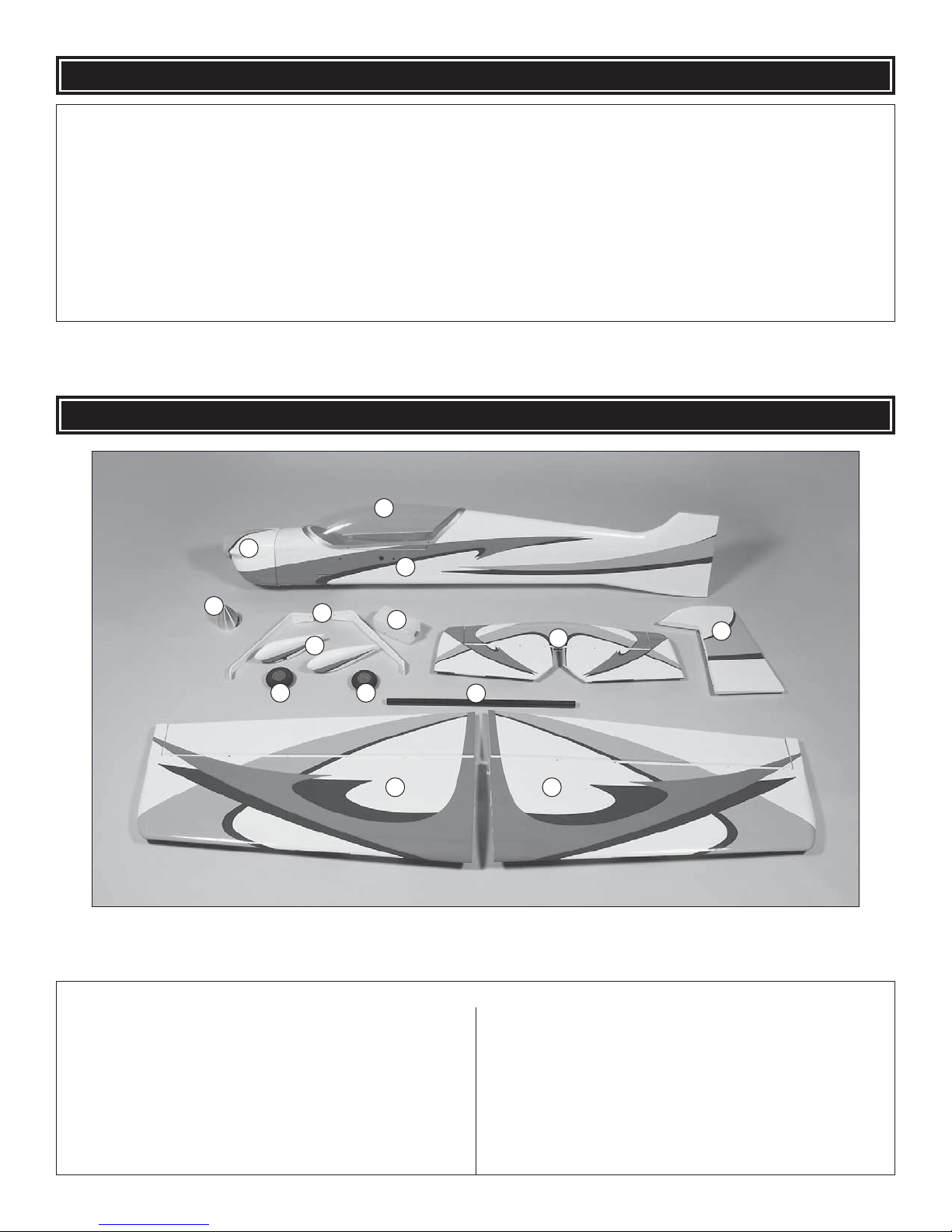
❏ 1. You will need the following supplies: Denatured alcohol,
30-minute epoxy, epoxy mixing cups, mixing sticks, round
toothpicks, petroleum jelly, masking tape, and some paper towels.
❏ ❏ 3. Fit the aileron tightly up against the wing and defl ect
it up and down a few times checking for binding.
❏ ❏ 4. Remove the aileron and the hinges. Prepare each
hinge fi rst by cleaning off any mold release compound left
on the parts during manufacture. Use denatured alcohol for
this. Prepare each hinge for gluing by thoroughly coating the
center section with petroleum jelly.
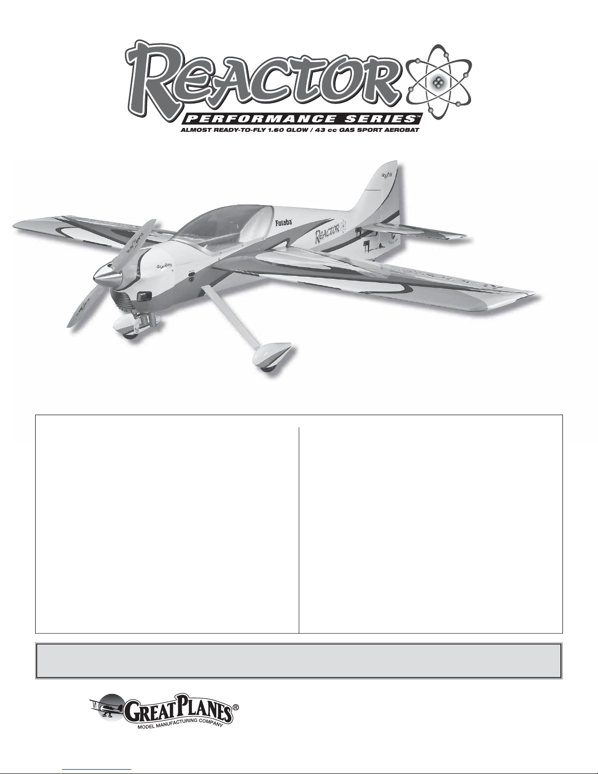
❏ ❏ 2. Start with the right wing and aileron. Install one 1-3/8"
[35mm] anti-rotation dowel in the location shown using epoxy.
❏ ❏ 5. Mix up a batch of 30-min ute epoxy and use a toothpick
to generously coat the inside of each hole or “pocket.” Apply
epoxy to both the wing pockets and the aileron pockets.
Warning: This glue joint is critical and you must take the
time to ensure it is done properly.
7
7
Page 8
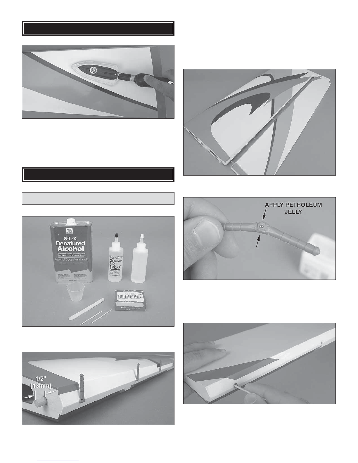
❏ ❏ 6. Dip both ends of each hinge (about tw o barbs deep)
into your epoxy cup.
❏ ❏ 7. Fit the hinges into the wing, making sure that you
align each one. Fit the aileron tightly and defl ect it a few
times in both directions. This will straighten any hinges that
are slightly out of alignment.
Install the Aileron Servos
T o get the best performance from your Reactor , we recommend
that you use four Futaba 9155 digital servos. These precision
servos have the right amount of torque (153 oz-in [11 kg-cm])
and will give you the best control. As a budget alternative you
can use a metal geared servo with a minimum 100 oz-in [7.2
kg-cm] torque rating but you should e xpect a slow er response
and some control blow-back at higher speeds. DO NOT use
only one aileron servo per wing, no matter what the torque
rating.
❏ ❏ 8. Clean up any excess epoxy that has squeezed out
of the pocket using a paper towel. Check both sides of the
hinge line.
❏ ❏ 9. Use masking tape to hold the aileron sn ug up against
the hinge line. Set the wing aside and allow the epo xy to fully
cure before you remove the tape or move the ailerons.
❏ 10. Repeat steps 2 through 9 for the left wing.
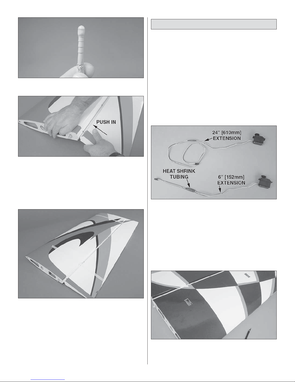
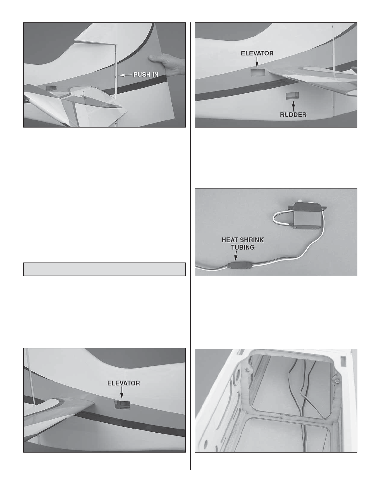
❏ ❏ 1. Prepare your outboard aileron servo with a 24"
[610mm] extension. Prepare the inboard servo with a 6"
[152mm] extension. Use heat shrink tubing to secure the
connectors so they do not come loose. Note: If you anticipate
mounting your radio equipment in the aft-most equipment
bay, you do not need the 6" [152mm] extensions installed.
❏ ❏ 2. Locate the aileron servo bays on the underside of
the wing and trim away the cov ering. If you have not done so
already , use a co vering iron to tack do wn the cov ering before
you trim.
8
8
Page 9
❏ ❏ 3. Starting with the outboard servo bay, tie the guide
string to the 24" [610mm] servo lead extension. Pull the
extension through the wing.
❏ ❏ 4. Place the aileron servos in position and use a 1/16"
[1.6mm] bit to drill the mounting holes for your servos into
the wing. Temporarily remove each servo and wick a few
drops of thin CA into the holes you drilled.
Assemble the Pushrods
In this section you will build the aileron pushrods as well as the
elevator and rudder pushrods. We’ll start with the four identical
aileron pushrods and fi nish with the others which you can set
aside to be used later. For this section you’ll need to have
some silver solder and liquid silver-solder fl ux. We recommend
using the Stay-Brite silver soldering kit (STAR2000).
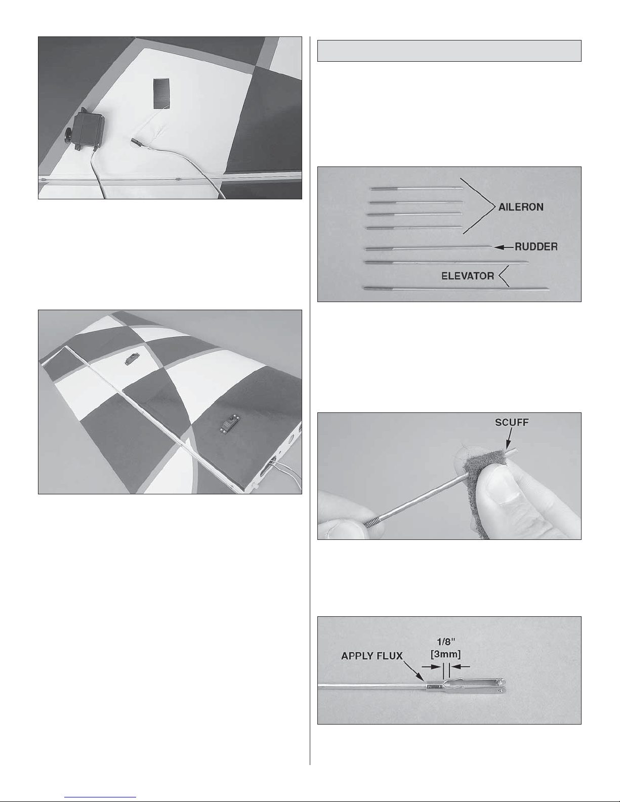
❏ ❏ 1. Locate the seven 4-40 x 12" [305mm] threaded
one end pushrods. You’ll need to cut the rods down to the
following lengths:
❏ ❏ 5. Install the aileron servos using the screws provided
with your servos.
❏ 6. Repeat steps 1 through 5 for the left wing.
A) Four (4) 3-1/2" [89mm] aileron pushrods
B) One (1) 4-1/2" [114mm] rudder pushrod
C) One (1) 5-1/4" [133mm] left elevator pushrod
D) One (1) 7-1/4" [184mm] right elevator pushrod
❏ ❏ 2. Starting with the aileron pushrods, gather the four
4-40 x 3-1/2" [89mm] threaded one end rods and four solid
metal (unthreaded) clevises. Roughen the unthreaded end
of each with some coarse 150-grit sandpaper or a coarse
Scotch Brite® pad.
❏ ❏ 3. Apply a f ew drops of soldering fl ux to the unthreaded
end of the pushrod. Position the clevis so that 1/8" [3mm] of
the pushrod protrudes past the barrel of the clevis.
9
Page 10
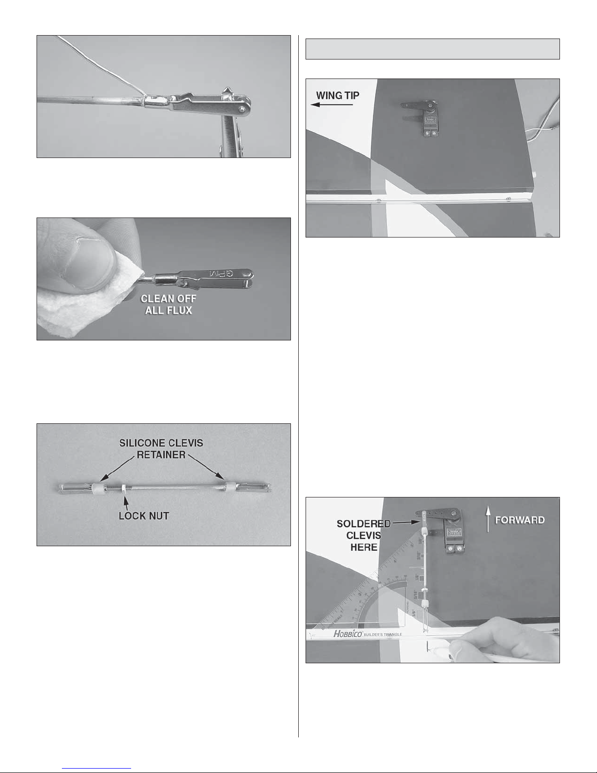
❏ ❏ 4. Use a hobby torch to heat both the clevis and the
pushrod. Apply silv er solder to the joint. The heat of the clevis
and the pushrod should melt the solder, not the direct fl ame
of the torch.
Install the Control Horns
❏ 1. Use your radio to center your aileron servos. Attach a
1-1/2" [38mm] single-sided servo arm (GPMM1105) to each
servo so that the arm is parallel with the hinge line when the
servo is centered. Install the arms so that they point outward
toward the wing tip.
❏ ❏ 5. While the joint is still hot b ut after the solder solidifi es
use a clean, damp cloth to wipe the fl ux from the joint before
it hardens. Flux is corrosiv e and m ust be thoroughly cleaned
from the joint.
❏ ❏ 6. Coat the joint with a thin fi lm of oil to prevent corrosion.
❏ ❏ 7. Fit a silicone retainer onto the rod, a 4-40 hex nut,
another silicone retainer, and a 4-40 threaded cle vis onto the
rod in that order. The threaded end of your pushrod should
look like the picture above.
❏ 8. Repeat steps 2 through 7 for the remaining pushrods.
❏ ❏ 2. Attach the soldered clevis end of each pushrod to
the servo arm in the hole that is 1-1/4" [32mm] out from the
center of the arm. Extend the pushrod straight back so that it
is 90° to the hinge line and draw a centerline on the aileron.
Use a builder’s triangle to ensure that the rod is 90° to the
hinge line.
10
Page 11
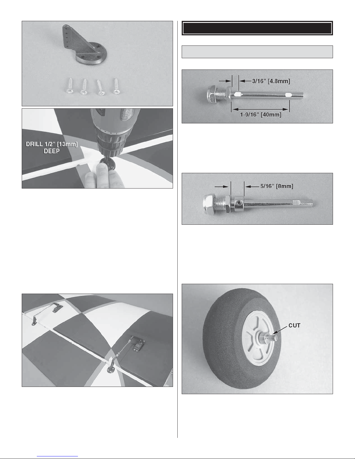
❏ ❏ 3. Center a control horn over the line that you made,
making sure that the clevis holes are also centered over the
hinge line. Hold the horn in position and use a 1/16" [1.6mm]
drill bit to drill four 1/2" [13mm] deep holes in the aileron. You
can wrap a piece of tape around the drill shank to help keep
you from drilling the holes too deep.
❏ ❏ 4. Use four #4 x 1/2" [13mm] sheet metal screws to
mount the control horns. Remove the screws and use thin
CA to harden the threads you created in the wood. Reinstall
the control horn.
BUILD THE FUSELAGE
Main Landing Gear Installation
❏ 1. Locate the 3/16" x 2" [4.8 x 51mm] axles, four 3/16"
[4.8mm] wheel collars, four set screws , tw o axle nuts , and the
two main wheels. File fl at spots in the axle in the locations
shown above .
❏ 2. Install the inner wheel collar so that the outer face of
the wheel collar is 5/16" [8mm] from the base of the axle.
Apply threadlocking compound to the set screw and tighten
the wheel collar in position. Install the wheel and the other
wheel collar.
Repeat steps 2 through 4 for the remaining aileron
control horns.
❏ 5. When you’re done installing all of the control horns,
adjust the length of your pushrods using the threaded clevis
and attach them to the control horns. Tighten the lock nuts
and position the silicone retainers after you have centered
the fl ight controls.
❏ 3. Use a rotary tool with a cutoff wheel attachment to cut
off the excess portion of the axle.
❏ 4. Prepare the other axle the same way.
11
Page 12
❏ 5. Attach the axles to the main landing gear legs using the
self-locking axle nut.
❏ 6. Trim the covering from the main landing gear slots in
the fuselage.
❏ 8. Attach the wheel pants to the landing gear legs using
four 4-40 x 1/2" [13mm] SHCS, four split ring lock washers,
and four #4 washers. Use threadlocking compound on the
screw threads.
Install the Horizontal Stabilizer
❏ 7. Use six 6-32 x 5/8" [16mm] SHCS, six #6 split ring lock
washers, and six #6 washers to attach the landing gear to
the fuselage. Use threadlocking compound on the screws.
Note: The landing gear is swept back.
❏ 1. Start by trimming the covering from the horizontal
stabilizer slot in the fuselage. Cut the covering from both
sides of the fuselage. Use your co vering iron to securely tack
the edges of the covering to the fuselage sides after you’re
done trimming.
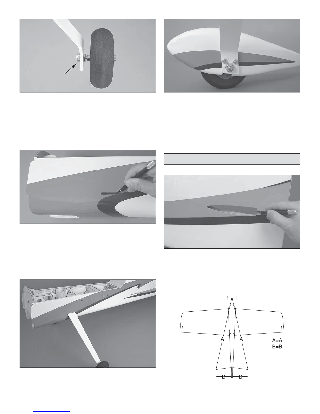
❏ 2. Slide the stab into the fuselage . Center it from left to right
and fore and aft, making sure that the distances are equal.
12
Page 13
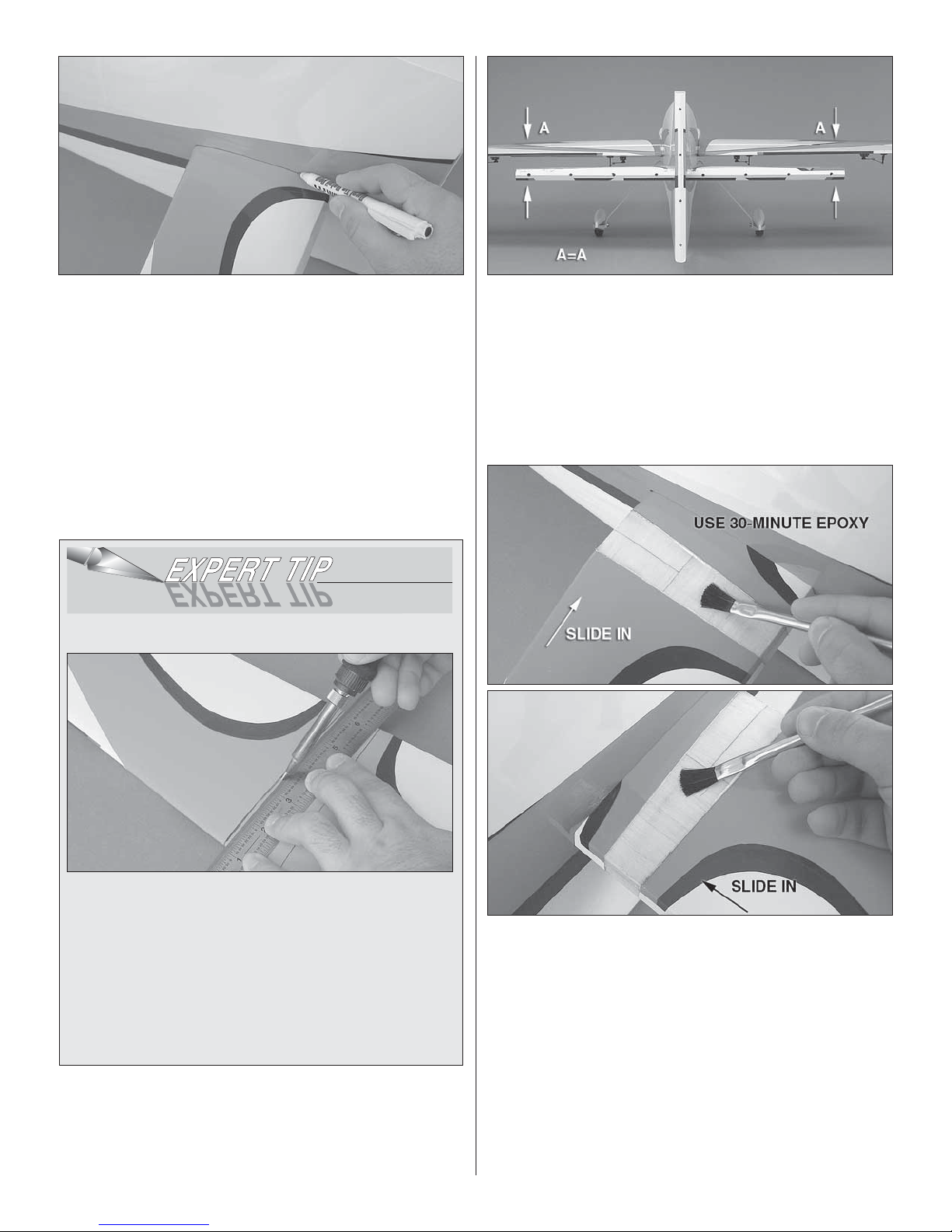
❏ 3. Holding the stab in position, use a fi ne-point, felt-tip
marker to trace lines onto the stab. Don’t forget to trace lines
on the bottom side of the stab, too.
❏ 4. Trim the covering along a line that is 3/32" [2.4mm]
inside of the lines you drew on the stab . Refer to the “Expert
Tip” below on how to cut away covering. When you’re done
trimming, wipe away the lines using alcohol.
HOW TO CUT COVERING FROM BALSA
❏ 6. Temporarily install the wings onto the fuselage using
the wing tube and the plastic 1/4-20 x 1" [25mm] wing bolts.
Fit the stab once again and check the alignment of the stab
with the wings by leveling the wings with your work surface
and then measuring the distance between that and the tips
of the stab. The distances from each stab tip should be equal
and the stab should be parallel with the wings. If there is a
slight misalignment, you may apply weight to the high side or
lightly sand the fuselage sides until the stab aligns.
Use a thin metal straightedge and a regular (15W)
soldering iron instead of a hobby knife to trim away your
covering. While a hobby knife may work, it damages the
underlying wood fi bers and can cause the stabilizer to
fail. Allow the iron to heat up to operating temperature.
Gently run the tip of the iron across the covering using
the straightedge as a guide. Move the iron at a rate that
melts the covering but does not burn the wood fi bers. A
few gentle passes are preferable to slower passes that
can damage the wood.
❏ 5. T rim the covering for the wing tube and wing dowels on
the fuselage.
❏ 7. Apply 30-minute epoxy to the top and bottom of the stab
center section and slide it into the fuselage. Pull the stab through
the fuselage past center and re-coat the center section on the
opposite fuselage side. Slide the stab back into the fuselage,
and then center it and level it lik e y ou did earlier.
❏ 8. Use paper towels and denatured alcohol to wipe away
any excess epo xy from the stab to fuselage joint. Check to see
that the stab stays in position and allow the epo xy to cure.
13
Page 14
Hinge the Horizontal Stabilizer
This section details the process for hinging the elevators.
We performed the operation using 30-minute epoxy. This is
generally enough time to do both elevators with one batch
if you are completely prepared. If you are worried about
accomplishing both sides, or you are working in a warm
climate, do one elevator at a time.
❏ 4. Fit the hinges into the stab, making sure to orient them
so that the hinge pin is parallel to the hingeline.
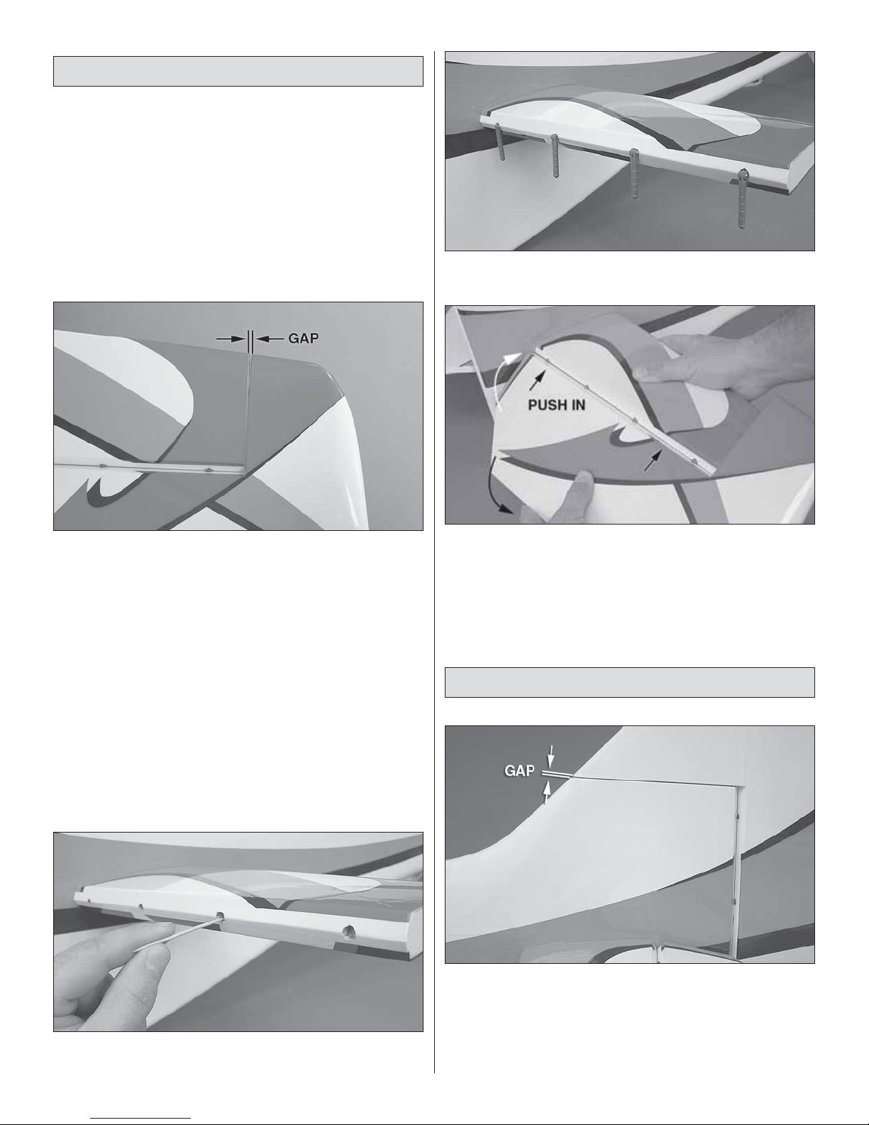
❏ 1. T est fi t eight hinges in the stab and then fi t the elevators.
Check for free movement of the elevators and that there is
a visible gap between the tip of the stab and the elevator
counterbalances. If the counterbalance interf ers with the stab ,
you should remove the covering from the tip of the stab and
sand off enough material until you get a good fi t You’ll have to
re-cover the area of wood you exposed. DO NOT attempt to
re-drill the hinge holes!
❏ 2. Remove the hinges and the elevators. Prepare the
hinges as you did earlier using petroleum jelly.
❏ 5. Install both elevators. Push each one up against the
hinge line. Defl ect them up and down so that the hinges align
properly. Use tape to hold the elevators level and up against
the hinge line like you did with the ailerons.
❏ 6. Allow the epoxy to cure before you remove the tape or
try to move the elevators.
Hinge the Rudder
❏ 3. Thoroughly coat the hinge pockets and the tips of each
hinge with 30-minute epoxy.
❏ 1. Test fi t the rudder using the four remaining hinges.
Check for free rudder movement and a visible gap between
the tip of the fi n and the rudder counterbalance.
❏ 2. Prepare the hinges as you did with the aileron and
elevator hinges.
14
Page 15
❏ 3. Use 30-minute epoxy to glue your hinges in place.
Remember to align them and to defl ect the rudder both ways
when you install it.
❏ 4. Use tape to hold your rudder in place while the
epoxy cures.
Install the Elevator & Rudder Servos
For the elevator and rudder servos, we recommend that you
use Futaba 9155 digital servos. For the elevators only, you
can use a metal geared servo with a minimum 100 oz-in [7.2
kg-cm] torque rating but you should expect a slower response
and control blow-back at higher speeds. Note: You must use
a servo with a minimum 150 oz-in [11 kg-cm] torque rating for
the rudder.
❏ 2. Trim the covering from the elevator and rudder servo
bays on the left side of the fuselage.
❏ 3. Attach a 36" [914mm] servo lead extension to the three
tail servos. If you anticipate mounting your receiver in the
aft-most equipment tray, you may use shorter servo lead
extensions.
❏ 1. Trim the covering from the elevator servo bay on the
right side of the fuselage as shown.
❏ 4. Fit your rudder and elevator servos in place. Route the
wires under the formers as shown.
15
Page 16

❏ 5. Install the ele vator and rudder servos. Use a 1/16" [1.6mm]
drill bit to drill the holes and use thin CA to harden the wood.
Install the Control Horns
❏ 3. Center a control horn over the line that you made
making sure that the clevis holes are also centered over the
hinge line. Hold the horn in position and use a 1/16" [1.6mm]
drill bit to drill four holes in the elevator. Remember to only
drill 1/2" [13mm] deep.
❏ 4. Use four #4 x 1/2" [13mm] sheet metal screws to mount
the elevator control horns. Remove the screws and use thin
CA to harden the threads you created in the wood. Reinstall
the control horn.
❏ 1. Center your servos. Attach a 1-1/2" [38mm] single-
sided servo arm to each servo so that the arm is 90° to the
servo case when the servo is centered. Install the arms so
that they point down.
❏ 2. Turn the fuselage over (a foam building stand is helpful
here). Use a felt-tip pen to make a mark on each elevator
that is 7/8" [22mm] from the side of the fuselage.
❏ 5. Make a line 2" [51mm] from the bottom edge of the
rudder. Dr ill the holes for the rudder horn and install it with
four #4 x 1/2" [13mm] sheet metal screws.
❏ 6. Install a 4-1/2" [114mm] pushrod to the rudder servo
and rudder. The pushrod should be installed on the servo
arm so that it is 1-1/4" [32mm] out from the center of the
servo arm and in the outermost hole of the control horn. Turn
on your radio and center the rudder by adjusting the clevis.
16
Page 17

❏ 7. Install the 5-1/4" [133mm] pushrod to the left elevator
servo and elevator.
❏ 8. Install the 7-1/4" [184mm] pushrod onto the right
elevator servo and elevator.
Tail Gear Installation
❏ 1. Locate the tail gear assembly. Remov e the wheel collar
and fi le a fl at spot on the axle where the set screw contacts
the axle. Apply threadlocking compound to the wheel collar
set screw and reinstall it.
❏ 4. Fit the tail gear assembly into the bushing and fi t the
tail gear retainer to the fuselage bottom as shown. Drill two
1/16" [1.6mm] holes into the fuselage using the retainer as a
guide. Remove the tail gear assembly.
❏ 5. Use the two 8mm sheet metal screws to attach the
retainer to the fuselage.
❏ 2. Turn the fuselage over. Trim the covering from the
tailwheel mounting hole. Use epoxy to glue the nylon b ushing
in place. Don’t get epoxy into the bushing.
❏ 3. Make a mark 4" [102mm] back from the hinge line on
the bottom of the rudder. Make sure that the mark is centered
and drill a 1/2" [13mm] deep hole here for the plastic tailwheel
guide wire post. Use a 3/32" [2.4mm] pilot drill bit and then
step up to a 5/32" [4mm] bit for the fi nal hole.
❏ 6. Loosen the tail gear collar set screw and remo ve the collar .
Position the collar under the tail gear retainer as you insert the
tail gear into the bushing. Do not tighten the collar y et.
❏ 7. Apply epoxy to the plastic tailwheel guide wire post and
slide it onto the tailwheel guide wire. Glue the post into the
hole you drilled in the bottom of the rudder.
17
Page 18

❏ 8. Adjust the tail gear’s position in the main bushing so
that the tail gear wire is 1/2" [13mm] from the bottom of the
fuselage. Use threadlocking compound on the set scre w and
tighten the collar.
ENGINE/MOTOR INSTALLATION
In this section we cover the installation of the Desert Aircraft
DA-50 gasoline engine, the O.S. 1.60 FX two-stroke glow
engine, and the Great Planes ElectriFly 80mm brushless
out-runner motor. Please jump to the section that applies to
your engine/motor installation.
Gas Engine Installation
This section will cover the installation of the Desert
Aircraft DA-50 engine. When you order your engine fr om
Desert Aircraft, make sure that you specify that y ou need
the 3” [76mm] standoff mounts and standard muffl er.
A template is provided for the DA-50 gas engine as well as for
the Fuji-Imvac™ BT-43 EI-2 engine. We recommend the DA-50
for the best 3D performance. The Fuji-Imvac BT-43 EI-2 is a
suitable sport fl ying alternative and installs in a relatively similar
manner. Note: Please use the included 12 x 20mm aluminum
spacers if you are installing the Fuji-Imvac BT-43 EI-2.
❏ 2. Locate two 2-56 threaded ball links and two 2-56 hex
nuts. Install one on the throttle arm and one on the choke
arm using threadlocking compound. Secure the ball links
using the 2-56 hex nuts.
❏ 3. Tur n to the back of this manual and cut out the drilling
template for the engine you’re using. Center the template by
matching the template crosshairs with the fi rewall crosshairs.
Tape it in place and use a 1/8" [3.2mm] drill bit to dr ill four
engine mount pilot holes in the fi rewall. A center punch or
scratch awl can be used to make a centering mark before
you drill. Follow up with a 1/4" [6.4mm] drill bit and enlarge
the holes.
❏ 1. Install the 3" [76mm] aluminum standoffs using the
hardware supplied by the engine manufacturer.
❏ 4. Drill out the throttle and choke pushrod holes using
a 3/16" [4.8mm] drill bit. Note: Some variants of the DA-50
have the throttle and choke arms located on the other side,
so please check your engine before you drill the holes.
18
Page 19

❏ 5. Cut a 1" [25mm] piece of outer pushrod tubing from
the 36" [914mm] length supplied. Install it in the fi rewall as
shown so that 1/4" [6.4mm] of the tube protrudes forward
from the fi rewall. Roughen the surface with sandpaper and
use epoxy to glue it in place.
❏ 8. Locate the 2-56 x 36" [914mm] threaded one end rod.
Measure 6" [152mm] from the unthreaded end and make a
mark. Cut the wire at the mark and retain this portion. This
will be referred to as “pushrod B.” The remaining portion of
the rod will be used for the throttle later.
❏ 9. Make a Z-bend at one end of pushrod B and a 90°
bend at the other end as shown. The last 3/4" [19mm] of rod
should be left for the 90° bend.
❏ 10. Locate the nylon bellcrank and drill out the outermost
holes in the arms using a 5/64" [2mm] drill bit.
❏ 6. Obtain f our 1/4-20 x 1-1/2" [38mm] SHCS, four 1/4" [6.4mm]
lock washers, and four 1/4" [6.4mm] washers (not included).
Locate the four included 12 x 20mm aluminum spacers. Install
the engine to the fi rewall using threadlocking compound on the
threads of the bolts as an added safety measure.
❏ 7. Locate the 2-56 x 6" [152mm] threaded one end rod.
Measure 2-1/2" [64mm] from the threaded end and make a
mark. Start your Z-bend at the mark so that the leg of the
bend is 2-1/2" [64mm] from the threaded tip. Clip off the
excess rod. This will be referred to as “pushrod A.”
❏ 11. Locate one 4-40 x 1-1/2" [38mm] cap screw, one #4
lock washer, two #4 washers, one brass bellcrank bushing,
one 4-40 nut, and one 1/2" x 1/2" x 1" [13 x 13 x 25.4mm]
pre-drilled wooden standoff block. Fit the bellcrank par ts in
the order shown.
❏ 12. Loosely position the bellcrank assemb ly as shown and
connect threaded pushrod A and pushrod B as shown. Apply
19
Page 20

threadlocking compound to the screw threads and install the
4-40 nut using a #4 washer and lock washer.
❏ 13. Thread a 2-56 nylon ball link socket onto pushrod A
as shown and attach it to the choke arm.
❏ 16. Locate the switch plate that fi ts your brand of radio
switch. Four plates are supplied: two Futaba switch & Ernst
charge jacks and two Hobbico heavy-duty & Ernst charge
jacks. Fit your switch and charge jack to the plate and use a
pen or pencil to draw an outline of the switch and jac k onto the
back side of the plate. Remove the switch and charge jack.
❏ 14. Locate the wood parts and build the fuel fi ller mount as
shown. Fuelproof the fi ller mount with a thin layer of epoxy.
❏ 15. Tur n the model over. Use epoxy to glue the fuel fi ller
mount to the exhaust tunnel. Use sandpaper to roughen the
surface to which the fuel fi ller mount will adhere.
❏ 17. Use two 7 x 22mm and two 6 x 29mm sticks to make
a fl ange for the charge plate.
❏ 18. Install the switch plate on the model using epoxy to
attach it. There are two forward locations reserved for the gas
engine’s ignition module. We chose the one on the left side.
❏ 19. Tack down the covering over the switch plate using a
covering iron set to a low temperature.
20
Page 21

❏ 20. Trim the covering from ov er the switch plate holes and
install the ignition switch and charge jack.
❏ 21. Wrap the shielded spark plug lead of the igniter unit
with electrical tape. This will help prevent damage of the
braided shield. Make sure that the battery leads you have
match the leads for your ignition module. We had to splice in
some new Futaba “J” leads to work with our battery.
❏ 23. Wrap your ignition module in 1/4" [6.4mm] thick R/C
latex foam rubber. Mount the ignition module to one of the
uprights or to the forward compartment fl oor using one of the
straps that you made.
❏ 24. Wrap the ignition battery in latex foam rubber. Mount
the battery using the other strap that you made.
❏ 22. Cut two 5" [127mm] strips of non-adhesive backed
hook and loop material. Make two sets of straps for your
ignition unit and ignition battery by joining a piece of “hook”
material to a piece of “loop” material.
❏ 25. Connect the ignition module to the ignition switch.
Connect the crank pickup to the ignition module. Connect
the ignition battery to the ignition switch. Use heat shrink
tubing to secure the connectors and a tie wrap to secure
them to the upright.
21
Page 22

❏ 26. Turn the model over. Wrap a tie wr ap around the spark
plug lead to make a “P” clamp. Route the spar k plug lead in
a fashion that keeps it away from the muffl er. Use a spare
servo screw to attach this to the side wall of the exhaust
box. Since a screwdriver won’t fi t, we suggest using a 1/4"
[6.4mm] socket with a #1 Phillips bit.
❏ 29. Build up the fuel tank stopper as shown and fi t the fuel
tubes. Solder the fuel line barbs in place.
❏ 30. Cut two pieces of fuel line so that each one is 5"
[127mm] long. Build up the fuel tank with the v ent line pointing
to the top of the tank. Secure the lines within the tank with
small tie wraps.
❏ 27. The fuel tank hardware that is supplied with this kit
is suitable for glow fuel only and cannot be used with
gasoline. For this reason we recommend the Sullivan
gasoline conversion kit (SULQ2684), fi ve fuel line barbs (2x
DUBQ0670), 36" [914mm] of Dubro 1/8" [3mm] Tygon fuel
tubing (DUBQ0493), and 24" [610mm] of Dubro neoprene
gas fuel line (in-tank) (DUBQ0455). Please retain the plastic
tank and the fuel clunks. These are approved for gas.
❏ 28. Cut one of the brass tubes in half. The other tube will
be used as your fuel vent.
❏ 31. Finish assembling your tank and tighten the stopper
screw. Be careful not to overtighten the stopper. This can
split the tank along the seam. You may want to use a felt-tip
pen to mark which direction the vent line is pointed so that
you know where the top of the tank is.
❏ 32. Cut two 8" [203mm] strips of hook and loop material. Join
each “hook” side to each “loop” side with a 2" [51mm] overlap.
22
Page 23

❏ 33. Fit fuel lines to the tank and install it using the two
straps you made. Route the fuel feed line to the carburetor.
Use small tie wraps to secure the fuel lines to the lines on
the tank.
Tape it in place and use a 3/16" [4.8mm] drill bit to dr ill four
engine mount holes on the fi rewall for the supplied engine
mount. A center punch or scr atch awl can be used to mak e a
centering mark before you drill.
❏ 2. If you are using the O.S. 1.60 FX tw o-stroke engine, drill
the hole for the throttle rod marked on the template. Use a
3/16" [4.8mm] drill bit for this.
❏ 3. Press four 8-32 blind nuts into the engine mount holes
you drilled. Press them in from the back side of the fi rewall.
You may need to use 8-32 bolts and washers to draw the
nuts into the holes.
❏ 34. Route the vent and fi ll lines through the fuel fi ller mount
and install a fuel fi ller plug.
Skip to the “Radio System Installation – Gas Engine”
section.
Glow Engine Installation
This section contains installation steps for the O.S. 1.60
FX two-stroke engine. The Great Planes engine mount
supplied with this model is rated for 1.20 to 1.80-sized
engines. If you are using an engine outside of this range,
please use a suitable engine mount rated for it.
❏ 4. Break the tangs out of each molded engine mount half
and grind off any remaining portion.
❏ 1. Tur n to the back of this manual and cut out the drilling
template for the engine you’re using. Center the template by
matching the template crosshairs with the fi rewall crosshairs.
❏ 5. Fit the two engine mount sides together. Center the
engine mount with the cross-hairs on the fi rewall and fi t
the mount to the fi rewall using four 8-32 x 1-1/4" [32mm]
SHCS, four #8 lock washers, and four #8 washers. Leave
the screws loose enough to adjust the width of the mounting
23
Page 24

beams. Position the engine on the mount so that the drive
washer is 7-1/4" [184mm] from the fi rewall. Clamp the
engine in this position. Drill and tap your engine mount using
an 8-32 tap set. Install the engine to the mount using four
8-32 x 1" [25mm] socket head cap screws (SHCS), four #8
lock washers, and four #8 washers.
❏ 6. Install the throttle servo in the center equipment tray as
shown. Use a 1/16" [1.6mm] drill bit f or the servo screw holes .
❏ 8. Trim the plastic pushrod tube so that there is at least 1/4"
[6.4mm] of tube protruding forward of the fi rewall and that
there is approximately 1-1/2" [38mm] of distance between
the throttle servo output shaft and the tube. When you’re
satisfi ed with the fi t of the pushrod tube, epoxy the fuel tank
supports in place. Roughen the outer surface of the pushrod
tube and epoxy it in place.
❏ 9. Install a screw-lock pushrod connector onto a short
servo arm. Use a plastic retainer to hold this to the servo
arm and a 4-40 x 1/4" [6.4mm] SHCS. Turn on your radio and
position the servo arm. Install the arm to your throttle servo
using the servo screw supplied with your servos.
❏ 10. Locate the 2-56 x 36" [914mm] threaded one-end rod,
one plastic clevis, and one silicone clevis retainer. Thread
the plastic clevis onto the rod so that at least 3/8" [10mm] of
thread is engaged. Slide a silicone retainer onto the rod and
fi t it into the pushrod tube.
❏ 7. Dry-fi t the fuel tank supports and route the plastic outer
pushrod tube from the fi rewall to the servo.
❏ 11. Locate two throttle rod standoffs. You will use these
to support the pushrod tube at the servo arm, so slide these
24
Page 25

onto the pushrod tube from inside the fuselage. Note: The
base of each standoff can be trimmed down for a custom fi t.
❏ 12. Slide the pushrod into the plastic tube and connect the
clevis to your throttle arm. Slide the other end of the pushrod
into the screw-lock pushrod connector. Bend the throttle
pushrod as needed to clear your muffl er or any obstructions.
❏ 13. Turn on your radio and adjust your throttle linkage.
Make sure that you can achieve full throttle, idle and throttle
cut-off. Apply thread-locking compound to the 4-40 x 1/4"
[6.4mm] SHCS and tighten it when you’re satisfi ed that the
throttle is rigged properly.
line pointing to the top of the tank. You may want to use a
felt-tip pen to mark which direction the vent line is pointed so
that you know where the top of the tank is.
❏ 16. Finish assembling your tank and tighten the stopper
screw. Be careful not to overtighten the stopper. This can
split the tank along the seam.
❏ 14. Fit and glue the pushrod supports to the fuselage
former just ahead of the throttle servo. Glue them so that the
pushrod aligns with the servo arm and won’t bind up when
the servo moves. Trim the excess pushrod wire, but leave
enough in case you want to make adjustments later.
❏ 15. Cut two pieces of fuel line so that each one is 5"
[127mm] long. Build up the fuel tank as shown with the vent
❏ 17. Fit fuel lines to the tank and install it using two #64
rubber bands. You may test fi t your muffl er at this point and
trim the vent line to length.
❏ 18. Locate the wood par ts and build the fuel fi ller mount
as shown.
25
Page 26

❏ 19. Tur n the model over. Use epoxy to glue the fuel fi ller
mount to the exhaust tunnel. Use sandpaper to roughen the
surface of where the fuel fi ller mount will adhere to.
Tape it in place and use a 9/32" [7.1mm] drill bit to dr ill four
motor mount holes on the fi rewall f or the Great Planes 80mm
Standoff Mount. A center punch or scratch awl can be used
to make a centering mark before you drill. Note: The Great
Planes 80mm RimFire Standoff Mount set (GPMG1275) is
available separately.
❏ 20. Test fi t the covered balsa sheet as shown. The sheet is
not “square.” It matches the angle of the fi rewall. Note: One
side has clear covering which must face outward.
Skip to the “Radio System Installation – Glow
Engine” section.
Electric Brushless Motor Installation
The electric power system shown in this section consists
of a Great Planes Electrifl y RimFire 80-75-230kV motor
(GPMG4800), a Kontronik Power Jazz 63V Brushless
120A ESC (KONM3140), and two FlightPower 22.2V
5000mAh 6S LiPo batteries in series (FPWP0364).
❏ 2. Prepare your motor by removing the motor mount
screws, the two f orw ard motor case set scre ws , and the rear
locking collar set screw. Apply threadlocking compound to
these and reinstall them.
❏ 1. Tur n to the back of this manual and cut out the drilling
template for the RimFire electric motor. Center the template by
matching the template crosshairs with the fi rewall crosshairs.
❏ 3. Install four 1/4-20 blind nuts in the fi rewall from the
back side.
26
Page 27

❏ 4. Locate four 50mm, 20mm, and 10mm standoff spacers
as well as eight mounting feet, four 1/4-20 x 5" [127mm]
bolts, four fl at washers, and four lock washers. Install the
motor using these parts as shown.
❏ 6. Use 80-grit sandpaper to roughen up the coated surface
of the fi rewall and the equipment tray where the ESC tray will
mount. Use epoxy to bond the ESC tray to the fuselage as
shown. A piece of triangle stock is supplied to help secure the
tray to the fi rewall.
❏ 7. If y our ESC must be held on with doub le-sided tape, mix
up some epoxy and thin it down with denatured alcohol. Coat
the bottom surface of the ESC tra y. Allow the epoxy to cure.
❏ 5. Build up the ESC tray as shown.
❏ 8. Mount y our ESC using double-sided tape or the method
specifi ed by the manufacturer.
Skip to the “Radio System Installation – Electric
Brushless” section.
27
Page 28

RADIO INSTALLATION
Radio System Installation – Gas Engine
❏ 1. Prepare an ignition switch plate as you did earlier.
❏ 2. Install the ignition switch plate on the model using
epoxy. A cutout for the switch plate is provided in the left and
right rear fuselage. You may choose either location.
❏ 3. Tack down the covering over the switch plate using a
covering iron set to a low temperature.
❏ 4. Trim the covering from over the switch plate holes and
install the ignition switch and charge jack.
❏ 5. Locate the aft equipment tray, the tray doubler and the
two side rails. Glue the tray doubler to the bottom of the tray.
Align the tabs on each rail with the corresponding slots in the
fuselage and glue each rail in place as shown.
❏ 6. Position the aft equipment tray in the aft bay and use a
1/16" [1.6mm] drill bit to drill six pilot holes through the side rails.
Harden the holes with thin CA. Use six #2 x 3/8" sheet metal
screws with six #2 washers to attach the aft equipment tra y.
28
Page 29

❏ 7. Install the throttle servo in the aft tray. Drill four 1/16"
[1.6mm] holes and harden them with thin CA. Note the
position of the servo output shaft.
❏ 10. Install a servo arm. Set your throttle servo to the full-
throttle position and connect the pushrod.
❏ 11. Locate one nylon ball link socket and one 2-56 x 1"
[25mm] threaded rod. Thread the rod into the ball link socket.
❏ 8. Locate the wood pushrod standoffs. Fit them to the gr ay
outer pushrod tube and install the tube. Route it clear of the
bellcrank and around the fuel tank. Trim the tube to fi t and
test fi t the standoffs.
❏ 9. Locate the 24" [610mm] plastic inner pushrod tube,
one 2-56 x 6" [152mm] threaded one-end rod, and one nylon
FasLink™. Trim the rod 2" [51mm] from the threaded end and
make an “L” bend. Thread the rod into one end of the inner
pushrod tube. This side will attach to your throttle servo arm.
❏ 12. Trim the inner pushrod tube to length and install the
ball link socket onto the throttle. Keep in mind that the throttle
is sprung shut and that you will have to hold it fully open
when you adjust the pushrod length.
29
Page 30

❏ 13. Position and glue the pushrod standoffs and the outer
pushrod tube in place.
❏ 14. Locate the non-adhesive backed hook and loop
material. Make tw o sets of straps for your receiv er and battery
by joining a piece of non-adhesive backed “hook” material to
a piece of “loop” material.
❏ 16. Wrap your receiver and battery pack with 1/4" [6.4mm]
thick latex foam. Use the straps you made to mount your
battery and receiver to the aft equipment tray.
❏ 17. Connect the battery to the switch. Use heat shrink tubing
to secure the connection between the battery and the switch.
❏ 15. Connect a Y -connector to each aileron channel. Connect
the other servo leads and the battery switch to your receiver.
❏ 18. We used a 2.4GHz radio system f or this build-up , but if
you’re using a 72MHz radio system an antenna routing tube
is provided for you in the upper left side of the fuselage.
Skip to the “Final Assembly” section.
30
Page 31

Radio System Installation – Glow Engine
❏ 1. Locate the switch plate that fi ts your brand of radio s witch.
Four plates are supplied: two Futaba switch & Ernst charge
jacks and two Hobbico heavy-duty & Ernst charge jacks. Fit
your switch and charge jack to the plate and use a pen or
pencil to draw an outline of the switch and jack onto the back
side of the plate. Remove the switch and charge jac k.
❏ 5. Trim the covering from over the switch plate holes and
install the switch and charge jack.
❏ 2. Use two 7 x 22mm and two 6 x 29mm sticks to make a
fl ange for the charge plate.
❏ 6. Locate the non-adhesive backed hook and loop
material. Make two sets of straps for your receiver and
battery by joining a piece of “hook” material to a piece of
“loop” material.
❏ 7. Connect a Y-connector to each aileron channel. Connect
the other servo leads to your receiver
❏ 3. Install the switch plate on the model using epoxy to
attach it. There are six places to mount the switch plate, so
choose the one that suits you best.
❏ 4. Tack down the covering over the switch plate using a
covering iron set to a low temperature.
❏ 8. Connect the battery to the switch and the switch to
the radio. Use heat shrink tubing to secure the connection
between the battery and the switch.
31
Page 32

❏ 9. Wrap your receiver and battery pack with 1/4" [6.4mm]
thick latex foam. Use the straps you made to mount your
battery and receiver to the center equipment tray.
❏ 10. We used a 2.4GHz radio system f or this build-up , but if
you’ re using a 72MHz radio system, an antenna routing tube
is provided for you in the upper left side of the fuselage.
Skip to the “Final Assembly” section.
❏ 2. Use two 7 x 22mm and two 6 x 29mm sticks to make a
fl ange for the charge plate.
❏ 3. Install the switch plate on the model using epoxy. For
C.G. reasons, the radio equipment is mounted in the aft
equipment bay. A cutout for the s witch plate is provided in the
left and right rear fuselage. You may choose either location.
Radio System Installation – Electric Brushless
❏ 1. Locate the switch plate that fi ts your brand of radio s witch.
Four plates are supplied: two Futaba switch & Ernst charge
jacks and two Hobbico heavy-duty & Ernst charge jacks. Fit
your switch and charge jack to the plate and use a pen or
pencil to draw an outline of the switch and jack onto the back
side of the plate. Remove the switch and charge jac k.
❏ 4. Tack down the covering over the switch plate using a
covering iron set to a low temperature.
❏ 5. Trim the covering from over the switch plate holes and
install the switch and charge jack. Iron the covering to the
switch plate before you begin trimming.
32
Page 33

❏ 6. Locate the aft equipment tray and the two side rails.
Align the tabs on each rail with the corresponding slots in the
fuselage and glue each rail in place as shown.
❏ 8. Locate the non-adhesive backed hook and loop
material. Make two sets of straps for your receiver and
battery by joining a piece of “hook” material to a piece of
“loop” material.
❏ 9. Connect a Y-connector to each aileron channel.
Connect the other servo leads, the battery switch, and your
ESC signal lead to your receiver.
❏ 7. Position the aft equipment tray in the aft bay and use a
1/16" [1.6mm] drill bit to drill six pilot holes through the side
rails. Use six #2 x 3/8" [10mm] sheet metal screws with six
#2 washers to attach the aft equipment tray.
❏ 10. Wrap your receiver and battery pack with 1/4" [6.4mm]
thick latex foam. Use the straps you made to mount your
battery and receiver to the aft equipment tray.
33
Page 34

❏ 11. Connect the battery to the switch. Use heat shrink tubing
to secure the connection between the battery and the switch.
FINAL ASSEMBLY
Cowl & Prop Installation
The following cowl installation instructions co ver the DA-50
gasoline engine. Trimming the cowl to fi t other engines may
require modifi cation of these procedures, but the basic idea
is the same. For the DA-50 or similar gas engines, a template
is provided in the back of this manual so that the engine
does not have to be removed. Other engine installations
may require removal of the engine while leaving the paper
templates in place. Note: If you’re using an electric motor,
cut at least one 3" x 1-1/2" [76.2 x 38.1mm] slot for cooling.
❏ 12. We used a 2.4GHz radio system f or this build-up , but if
you’ re using a 72MHz radio system, an antenna routing tube
is provided for you in the upper left side of the fuselage.
❏ 13. Use the remaining hook and loop material to make
battery straps for your LiPo battery packs.
❏ 14. Read the “Motor & Battery Safety” section. Visually
inspect your motor and ESC wiring and check for an y shorts,
bad solder joints, or open connections. Without a propeller
attached, turn on your transmitter and receiver. Plug a LiPo
battery into your ESC, arm the ESC, and slowly advance
the throttle to check for proper direction of rotation from the
motor. If the motor does not rotate clockwise (as viewed
from the “pilot’ s” seat), swap any two motor leads. Note: The
throttle channel may need to be rev ersed in your radio bef ore
you are able to successfully arm your ESC.
❏ 1. If you’re using a gas engine inverted, turn to the back
of this manual and cut out the paper template. F old along the
dotted line and center the template along the bottom of the
cowl. The folded edge holds the template in position. Trace a
line around the template using a felt-tip marker and trim out
the clearance hole.
❏ 2. Tape a suitably sized piece of card stock to the fuselage
side and use it as a template to trim a clearance hole for your
muffl er. If y ou’re working with a side mounted glow engine, you
will use this method to make a template for the cylinder head.
Use cardstock to trim holes for your engine's needle v alv es .
34
Page 35

❏ 3. Remo ve the muffl er while leaving the template in place.
❏ 4. Locate the wood parts shown.
❏ 6. Fit the cowl centering tool to the cowl as shown. Use
only two small drops of medium CA to tack the inside and
the outside pieces together so that you can remove them
easily later.
❏ 5. Build the inside portion and the outside portion of cowl
centering tool as shown. Use medium CA to glue them together.
❏ 7. Fit the cowl to the plane so that the cowl centering tool
bottoms out on the engine’s drive washer. Position the paper
template and trace the muffl er cutout onto the cowl using a felttip pen.
❏ 8. Trim the clearance hole for the muffl er. Reinstall your
muffl er and check the fi t.
35
Page 36

❏ 9. Temporarily fi t the canopy and hatch. Fit the cowl once
again, making sure to slide it back until the centering tool
contacts the drive washer. Use a 1/16" [1.6mm] drill bit to
make four 1/2" [13mm] deep holes in the fuselage sides (two
per side). Drill them so that they are 1/2" [13mm] from the
rear edge of the cowl. Apply thin CA to the holes to harden
the wood.
Wing Installation
❏ 1. T rim the covering from the fuselage sides in the following
locations: f our canop y screw holes , two wing tube holes , four
wing bolt holes, two TE wing dowel holes, and two servo
wire holes.
❏ 10. Locate the four 9mm wooden reinforcement discs.
Center them over the screw holes you drilled in the cowl.
Glue them into position. Remove the cowl centering tool
from the cowl.
❏ 11. Use four #4 x 1/2" [13mm] sheet metal screws along
with four Dubro #4 nylon washers to install your cowl.
❏ 2. Locate the 24-1/2" [620mm] wing tube and slide it into
the fuselage.
❏ 3. Pull the aileron servo leads into the fuselage and install the
wings using four 1/4" x 1" [6.4 x 25mm] nylon wing bolts. Connect
the aileron servo leads to the Y-harnesses on your receiv er .
36
Page 37

Canopy Installation
❏ 1. Locate the two 1" [25mm] wooden dowels and glue
them into the canopy so that they are 1/4" [6.4mm] from the
front face of the former.
❏ 2. Remove the seven canopy screws and remove the
clear plastic canopy from the frame. Harden the screw holes
with one drop of thin CA. More than one drop will melt the
foam under the sheeting, so be careful. Apply the instrument
panel decal to the instrument panel.
GET THE MODEL READY TO FLY
Check the Control Directions
❏ 1. T urn on the transmitter and receiver and center the trims.
If necessary, remove the servo arms from the servos and
reposition them so they are centered. Reinstall the screws
that hold on the servo arms using threadlocking compound.
❏ 2. With the transmitter and receiver still on, check all the
control surfaces to see that they are centered. If necessar y,
adjust the clevises on the pushrods to center the control
surfaces. Move the controls and make sure there is no
mechanical binding or interference.
❏ 3. Reinstall the clear plastic canopy on the frame using
the seven screws you removed earlier.
❏ 4. Fit the canopy hatch to the model and use four 4-40 x
5/8" [16mm] Phillips head screws, four #4 lock washers, and
four #4 washers. Apply a drop of threadlocking compound to
the screw threads periodically so that you don’t lose these
screws in fl ight.
❏ 3. Make certain that the control surfaces and the carburetor
respond in the correct direction as shown in the diagram.
If any of the controls respond in the wrong direction, use
the servo reversing in the transmitter to reverse the servos
connected to those controls. Be certain the control surfaces
have remained centered. Adjust if necessary.
37
Page 38

Set the Control Throws
To ensure a successful fi rst fl ight, fl y your Reactor set
up only according to the C.G. and control surface throws
specifi ed in this manual. The throws and C.G. are not
arbitrary, but have been determined through extensive
testing and accurate record-keeping. This provides you
with the best chance for success and enjoy ab le fi rst fl ights
that should be surprise-free. Additionally, the throws and
C.G. shown are true, real data which will allow the model to
perform in the manner in which it was intended when fl own
by a pilot of the skill level for which it was intended. DO
NOT OVERLOOK THESE IMPORTANT PROCEDURES.
A model that is not properly setup may be unstable and
possibly unfl yable.
These are the recommended control surface throws:
HIGH RATE
ELEVATOR: 1-1/2" [38mm], 15° up
1-1/2" [38mm], 15° down
RUDDER: 4-3/4" [121mm], 28° left
4-3/4" [121mm], 28° right
AILERONS: 2-1/2" [64mm], 19° up
2-1/2" [64mm], 19° down
LOW RATE
ELEVATOR: 1" [25mm], 10° up
1" [25mm], 10° down
RUDDER: 2-3/4" [70mm], 16° left
2-3/4" [70mm], 16° right
AILERONS: 1-1/2" [38mm], 11° up
1-1/2" [38mm], 11° down
3D RATE
ELEVATOR: 3-1/4" [83mm], 34° up
3-1/4" [83mm], 34° down
RUDDER: 5-3/4" [146mm], 35° left
5-3/4" [146mm], 35° right
Use a ruler, an inclinometer, or a protractor to accurately
measure and set the control throw of each control surface
as indicated in the chart that follows. If your radio does not
have dual rates, we recommend setting the throws at the
high rate setting.
Note: The throws are measured at the widest part of the
elevators, rudder and ailerons.
AILERONS: 4-1/2" [114mm], 36° up
4-1/2" [114mm], 36° down
Balance Your Model (C.G.)
❏ 1. Using a black felt-tipped pen, make a mark on the
bottom of each wing that is 7" [178mm] from the LE of the
root wing rib. This is the ideal balance point and this is where
your plane should balance for the fi rst few fl ights. If you wish
to experiment with the C.G., you may do so after you have
become comfortable with the plane. The forward C.G. limit
is 6.5" [165mm] from the LE of the root rib. The aft limit is
8" [203mm] from the LE of the root rib.
38
Page 39

❏ 2. With the wing attached to the fuselage, all parts of the
model installed (ready to fl y) and an empty fuel tank, place
the model on a Great Planes C.G. Machine, or lift it at the
balance point you marked.
❏ 3. If the tail drops, the model is “tail heavy” and the battery
pack and/or receiver must be shifted forward or weight must
be added to the nose to balance. If the nose drops, the
model is “nose heavy” and the battery pack and/or receiver
must be shifted aft or weight must be added to the tail to
balance. Moving radio equipment to achieve proper balance
is an option when using the electric or glow setup. Because
gasoline engines generate electrical noise, all components
involved in spark generation must be kept away from radio
equipment. Lead ballast weight is available to help you
balance your airplane. Use Great Planes (GPMQ4485) “stickon” lead. A good place to add stick-on nose weight is to the
fi rewall (don’t attach weight to the cowl–it is not intended to
support weight). Begin by placing incrementally increasing
amounts of weight on the top of the fuse over the fi rewall
until the model balances. Once you have determined the
amount of weight required, it can be permanently attached.
If required, tail weight may be added by cutting open the
bottom of the fuse and gluing it permanently inside.
PREFLIGHT
Identify Y our Model
No matter if you fl y at an AMA sanctioned R/C club site or if
you fl y somewhere on your own, you should alwa ys hav e your
name, address, telephone number and AMA number on or
inside your model. It is required at all AMA R/C club fl ying sites
and AMA sanctioned fl ying events. Fill out the identifi cation
tag on page 43 and place it on or inside your model.
Charge Your Radio Batteries
Follow the battery charging instructions that came with your
radio control system to charge the batteries. You should
always charge your transmitter and receiver batteries the
night before you go fl ying, and at other times as recommended
by the radio manufacturer. If you have installed a gasoline
engine with an electronic ignition, make sure that you also
charge its battery pack. Carry a voltmeter in your fi eld box
and check the voltage of your batteries before each fl ight.
CAUTION: Unless the instructions that came with your
radio system state differently, the initial charge on new
transmitter and receiver batteries should be done for 15
hours using the slow-charger that came with the radio
system. This will “condition” the batteries so that the next
charge may be done using the fast-charger of y our choice .
If the initial charge is done with a fast-charger , the batteries
may not reach their full capacity and you ma y be fl ying with
batteries that are only partially charged.
Note: Do not rely upon the adhesiv e on the back of the lead
weight to permanently hold it in place. Over time, fuel and
exhaust residue may soften the adhesive and cause the
weight to fall off . Use #2 sheet metal screws, RTV silicone or
epoxy to permanently hold the weight in place.
4. IMPORTANT: If you found it necessary to add any weight,
recheck the C.G. after the ballast weight has been installed.
Balance the Model Laterally
❏ 1. With the wings level, have an assistant help you lift the
model by the engine propeller shaft and the bottom of the
fuselage under the TE of the fi n. Do this several times.
❏ 2. If one wing always drops when y ou lift the model, it means
that side is heavy . Balance the airplane by adding weight to the
other wing tip. An airplane that has been laterall y balanced
will track better in loops and other maneuvers.
Ground Check & Range Check
Run the engine for a fe w minutes to mak e sure it idles reliably,
transitions smoothly and maintains full power indefi nitely .
Afterward, shut the engine off and inspect the model closely,
making sure all fasteners, pushrods and connections have
remained tight and the hinges are secure. Always ground
check the operational range of your r adio bef ore the fi rst fl ight
of the day following the manufacturer’s instructions that came
with your radio. This should be done once with the engine off
and once with the engine running at various speeds. If the
control surfaces do not respond correctly, do not fl y! Find and
correct the problem fi rst. Look for loose servo connections
or broken wires, corroded wires on old servo connectors,
poor solder joints in your battery pack, a defective cell, or a
damaged receiver crystal from a previous crash.
39
Page 40

ENGINE & MOTOR SAFETY PRECAUTIONS
Failure to follow these safety precautions may result
in severe injury to yourself and others.
Keep all engine fuel in a safe place, away from high heat,
sparks or fl ames, as fuel is very fl ammable. Do not smoke
near the engine or fuel; and remember that engine exhaust
gives off a great deal of deadly carbon monoxide. Therefore,
do not run the engine in a closed room or garage.
Get help from an experienced pilot when learning to
operate engines.
Use safety glasses when starting or running engines
and motors.
Do not run the engine or motor in an area of loose gravel or sand;
the propeller may throw such material in your f ace or e yes .
Keep your f ace and body as w ell as all spectators a wa y from
the plane of rotation of the propeller as you start and run the
engine or motor.
Make sure that all electrical connections are soldered
properly . Run the motor f or a f ew minutes and then chec k the
wires and connections for excessive heat. Hot connections
may indicate poor solder joints.
Keep these items away from the prop: loose clothing, shirt
sleeves, sweater strings, ties, scarfs, long hair or loose
objects such as pencils or screwdrivers that may fall out of
shirt or jacket pockets into the prop.
Use a “chicken stick” or electric starter to start the engine.
Do not use your fi ngers to fl ip the propeller. Mak e certain the
glow plug clip or connector is secure so that it will not pop off
or otherwise get into the running propeller.
Make all engine adjustments from behind the rotating propeller .
The engine gets hot! Do not touch it during or right after
operation. Make sure fuel lines are in good condition so fuel
will not leak onto a hot engine, causing a fi re.
To stop a glow engine, cut off the fuel supply by closing
off the fuel line or following the engine manufacturer’s
recommendations. Do not use hands, fi ngers or any other
body part to try to stop the engine. To stop a gasoline powered
engine an on/off switch should be connected to the engine
coil or igniter unit. Do not thro w an ything into the propeller of
a running engine or motor.
Always keep your radio on when plugging the motor batteries
into the ESC. Stay clear of the propeller at all times: some ESC
units do not have saf ety arming features, so an y mov ement of
the throttle stick may cause the propeller to turn.
Always check your motor and battery setup using a watt
meter. We recommend the RC Electronics Watt’s Up meter
(RELP0101). When using the recommended setup you
should be able to match the voltage, current, and prop rpm
we have listed in this manual.
LITHIUM BATTERY HANDLING & USAGE
WARNING!! Read the entire instruction sheet included
with the battery. Failure to follow all instructions
could cause permanent damage to the battery and its
surroundings, and cause bodily harm!
• ONLY use a LiPo approved charger.
• NEVER charge in excess of 4.20V per cell.
• ONLY charge through the “charge” lead. NEVER charge
through the “discharge” lead.
• NEVER charge at currents greater than 1C.
• ALW AYS set charger’s output v olts to match battery volts .
• ALWAYS charge in a fi reproof location.
• NEVER trickle charge.
• NEVER allow battery temperature to exceed 150° F [65° C].
• NEVER disassemble or modify pack wiring in any way or
puncture cells.
• NEVER discharge below 2.5V per cell
• NEVER place on combustible materials or leav e unattended
during charge or discharge.
• ALWAYS KEEP OUT OF REACH OF CHILDREN.
40
Page 41

Battery Precautions/Connecting Batteries
This is how to connect four batteries in Series:
Batteries of different voltages, but not different capacities
may also be connected in Series:
These are three 11.1V, 3200mAh batteries and
one 7.4V, 3200mAh battery. When joined in Series,
the result will be a 40.7V, 3200mAh battery.
Connecting batteries in “Series” means to connect the +’s
to the –’s and the –’s to the +’s. This combines the batteries’
voltages, but the capacity remains the same.
7.4V (3-cell)
3200mAh
18.5V
3200mAh
11.1V (3-cell)
3200mAh
40.7V
3200mAh
11.1V (3-cell)
3200mAh
22.2V
3200mAh
11.1V (3-cell)
3200mAh
It’s okay to connect batteries with different Voltages
in Series to achieve the new, desired Voltage.
This is how to connect three batteries in Series:
AMA SAFETY CODE (excerpts)
Read and abide by the following excerpts from the Academy
of Model Aeronautics Safety Code. For the complete Safety
Code refer to Model A viation magazine, the AMA web site or
the Code that came with your AMA license.
General
1) I will not fl y my model aircraft in sanctioned ev ents, air shows,
or model fl ying demonstrations until it has been proven to be
airworthy by having been pre viously, successfully fl ight tested.
2) I will not fl y my model aircraft higher than approximately
400 feet within 3 miles of an airport without notifying the
airport operator . I will give right-of-way and avoid fl ying in the
41
Page 42

proximity of full-scale aircraft. Where necessary, an observer
shall be utilized to supervise fl ying to avoid having models fl y
in the proximity of full-scale aircraft.
3) Where established, I will abide by the safety rules for the
fl ying site I use, and I will not willfully and deliberately fl y my
models in a careless, reckless and/or dangerous manner.
5) I will not fl y my model unless it is identifi ed with my name
and address or AMA number, on or in the model. Note: This
does not apply to models while being fl own indoors.
7) I will not operate models with pyrotechnics (any device
that explodes, burns, or propels a projectile of any kind).
Radio Control
1) I will have completed a successful radio equipment ground
check before the fi rst fl ight of a new or repaired model.
2) I will not fl y my model aircraft in the presence of spectators
until I become a qualifi ed fl ier, unless assisted by an
experienced helper.
3) At all fl ying sites a straight or curved line(s) must be
established in front of which all fl ying takes place with the
other side for spectators. Only personnel involved with fl ying
the aircraft are allowed at or in the front of the fl ight line.
Intentional fl ying behind the fl ight line is prohibited.
4) I will operate my model using only radio control frequencies
currently allowed by the F ederal Communications Commission.
5) I will not knowingly operate my model within three
miles of any pre-existing fl ying site except in accordance
with the frequency sharing agreement listed (in the
complete AMA Safety Code).
9) Under no circumstances may a pilot or other person
touch a powered model in fl ight; nor should any part of the
model other than the landing gear, intentionally touch
the ground, except while landing.
CHECK LIST
During the last few moments of preparation your mind may
be elsewhere anticipating the excitement of the fi rst fl ight.
Because of this, you may be more likely to overlook certain
checks and procedures that should be performed before the
model is fl own. To help avoid this, a check list is provided to
make sure these important areas are not overlooked. Man y
are covered in the instruction manual, so where appropriate,
refer to the manual for complete instructions. Be sure to
check the items off as they are completed.
❏ 3. Be certain the battery and receiver are securely
mounted in the fuselage. Simply stuffi ng them into
place with foam rubber is not suffi cient.
❏ 4. Extend your receiver antenna and make sure it has a
strain relief inside the fuselage to keep tension off the
solder joint inside the receiver.
❏ 5. Balance your model laterally as explained in
the instructions.
❏ 6. Use threadlocking compound to secure critical
fasteners such as the set screws that hold the wheel
axles to the struts, screws that hold the carburetor arm
(if applicable), screw-lock pushrod connectors, etc.
❏ 7. Add a drop of oil to the axles so the wheels will
turn freely.
❏ 8. Make sure all hinges are securely glued in place.
❏ 9. Reinforce holes for wood screws with thin CA where
appropriate (servo mounting screws, cowl mounting
screws, etc.).
❏ 10. Confi rm that all controls operate in the correct direction
and the throws are set up according to the manual.
❏ 11. Set up and check a throttle cutoff on your radio.
❏ 12. Make sure there are silicone retainers on all the
clevises and that all servo arms are secured to the
servos with the screws included with your radio.
❏ 13. Tighten all jam nuts against the threaded clevises on
your control surfaces.
❏ 14. Secure connections between servo wires and
Y-connectors or servo extensions, and the connection
between your battery pack(s) and the on/off switch
with vinyl tape, heat shrink tubing or special clips
suitable for that purpose.
❏ 15. Make sure any servo extension cords you may have
used do not interfere with other systems (servo arms,
pushrods, etc.).
❏ 16. Secure the pressure tap (if used) to the muffl er with
high temp RTV silicone, threadlocking compound or
J.B. Weld.
❏ 17. Make sure the fuel lines are connected and are
not kinked.
❏ 18. Balance your propeller (and spare propellers).
❏ 19. Tighten the propeller nut and spinner.
❏ 20. Place your name, address, AMA number and telephone
number on or inside your model.
❏ 21. Cycle your receiver battery pack (if necessary) and
make sure it is fully charged.
❏ 22. Range check your r adio at the fi eld at the start of each
fl ying day. Check it with the engine/motor operating.
❏ 1. Fuelproof all areas exposed to fuel or e xhaust residue.
❏ 2. Check the C.G. according to the measurements
provided in the manual.
42
Page 43

FLYING
Fuel Mixture Adjustments
A fully cowled engine may run at a higher temperature than
an un-cowled engine. For this reason, the fuel mixture should
be richened so the engine runs at about 200 rpm below
peak speed. By running the engine slightly rich, you will help
prevent dead-stick landings caused by overheating.
CAUTION (THIS APPLIES TO ALL R/C AIRPLANES): If,
while fl ying, you notice an alarming or unusual sound such
as a low-pitched “buzz,” this may indicate control surface
fl utter. Flutter occurs when a control surface (such as an
aileron or elevator) or a fl ying surface (such as a wing or
stab) rapidly vibrates up and down (thus causing the noise).
In extreme cases, if not detected immediately, fl utter can
actually cause the control surface to detach or the fl ying
surface to fail, thus causing loss of control followed by
an impending crash. The best thing to do when fl utter is
detected is to slow the model immediately by reducing
power , then land as soon as saf ely possible . Identify which
surface fl uttered (so the problem may be resolved) by
checking all the servo grommets for deterioration or signs of
vibration. Make certain all pushrod linkages are secure and
free of play. If it fl uttered once, under similar circumstances
it will probably fl utter again unless the problem is fi xed.
Some things which can cause fl utter are; Excessive hinge
gap; Not mounting control horns solidly; Poor fi t of clevis
pin in horn; Side-play of wire pushrods caused by large
bends; Excessive free play in servo gears; Insecure servo
mounting; and one of the most prevalent causes of fl utter;
Flying an over-powered model at excessive speeds.
Takeoff
Before you get ready to takeoff, see how the model handles
on the ground by doing a few practice runs at low speeds
on the runway. Hold “up” elevator to keep the tail wheel on
the ground. If necessary, adjust the tail wheel so the model
will roll straight down the runway. If you need to calm your
nerves before the maiden fl ight, shut the engine down and
bring the model back into the pits. Top off the fuel, then check
all fasteners and control linkages.
air. At this moment it is likely that you will need to apply more
right rudder to counteract engine torque. Be smooth on the
elevator stic k, allo wing the model to estab lish a gentle climb
to a safe altitude before turning into the traffi c pattern.
Flight
For reassurance and to keep an eye on other traffi c, it is a
good idea to have an assistant on the fl ight line with you. Tell
him to remind you to throttle back once the plane gets to a
comfortable altitude. While full throttle is usually desir able f or
takeoff, most models fl y more smoothly at reduced speeds.
T ake it easy with your airplane for the fi rst few fl ights, gradually
getting acquainted with it as you gain confi dence. Adjust the
trims to maintain straight and level fl ight. After fl ying around
for a while, and while still at a saf e altitude with plenty of fuel,
practice slow fl ight and execute practice landing approaches
by reducing the throttle to see how the model handles at
slower speeds. Make a few more runs minding your fi eld’s
current traffi c pattern and try executing a few straight-ahead
stalls. Add po w er to see ho w she climbs as w ell. Continue to
fl y around, executing various maneuvers and making mental
notes (or having your assistant write them down) of what trim
or C.G. changes may be required to fi ne tune the model so
it fl ies the way you like. Mind your fuel level, but use this fi rst
fl ight to become familiar with your model before landing.
Landing
To initiate a landing approach, lower the throttle while on the
downwind leg. Allow the nose of the model to pitch do wnw ard
to gradually bleed off altitude. Continue to lose altitude, but
maintain airspeed by keeping the nose down as y ou turn onto
the crosswind leg. Make your fi nal turn toward the runway (into
the wind) keeping the nose down to maintain airspeed and
control. Le vel the attitude when the model reaches the runwa y
threshold, modulating the throttle as necessary to maintain
your glide path and airspeed. If you are going to overshoot,
smoothly advance the throttle (always ready on the right
rudder to counteract torque) and climb out to make another
attempt. When you’re ready to make your landing fl are and
the model is a foot or so off the deck, smoothly increase up
elevator until it gently touches do wn. Once the model is on the
runway and has lost fl ying speed, hold up elevator to place the
tail on the ground, regaining tail wheel control.
Remember to takeoff into the wind. When you’re ready, point
the model straight down the runway, hold a bit of up elevator
to keep the tail on the ground to maintain tail wheel steering,
and then gradually advance the throttle. As the model gains
speed, decrease up elevator, allowing the tail to come off
the ground naturally. One of the most important things to
remember with a tail dragger is to always be ready to apply
right rudder to counteract engine torque. Gain as much
speed as your runway and fl ying site will practically allow
before gently applying up elevator, lifting the model into the
One fi nal note about fl ying your model. Have a goal or fl ight
plan in mind for every fl ight. This can be learning a new
maneuver(s), improving a maneuver(s) you already know,
or learning how the model behaves in certain conditions
(such as on high or low rates). This is not necessarily to
improve your skills (though it is never a bad idea!), but more
importantly so you do not surprise yourself by impulsively
attempting a maneuver and suddenly fi nding that you’ve run
out of time, altitude, or airspeed. Every maneuver should be
deliberate, not impulsive. For example, if you’re going to do a
43
Page 44

loop, check y our altitude, mind the wind direction (anticipating
rudder corrections that will be required to maintain heading),
remember to throttle back at the top, and make certain you
are on the desired rates (high/low rates). A fl ight plan greatly
reduces the chances of crashing your model just because of
poor planning and impulsive moves. Remember to think.
begins to point downwards, reduce the throttle (to keep the
model from being pulled downwards). As the model fl attens
out, add power to pull the model around. Many models will
require some rudder correction (usually right rudder) during
this maneuver . Some planes will require aileron correction to
keep the wings level.
Have a ball!
But always stay in control and fl y in a safe manner.
GOOD LUCK AND GREAT FLYING!
Make a copy of this identifi cation tag and put it on or
inside your model.
3D FLYING
Because of the power-to-weight ratio on 3D planes, str aightand-level fl ight should be at a reduced throttle and full power
should be used only when the airplane is “loaded” during
a maneuver. Learn to manage the throttle and experiment
while in the maneuver . The power needed will depend on the
maneuver being performed. C.G. also plays a large role in
the 3D capability of models as well. Experiment, but keep in
mind that being tail heavy is not always the best way to go.
Another thing to remember is that maximum control throw is
not necessary for all 3D maneuvers. Occasionally, too much
throw can place the model too far into a stall, causing it to
become uncontrollable. Practice your maneuvers at a higher
altitude while you become accustomed to your particular
plane’s stall characteristics.
WATERFALLS
UPRIGHT FLAT SPINS
Pull the nose up slightly and slowly decrease power. As the
model slows to a few mph, slowly apply full left rudder and
power. Next, start adding up elevator as needed to keep the
model fl at in the spin. Most airplanes will require some aileron
as well to keep the wings level. This is one of the maneuvers
to experiment on; try different C.G. positions and different
amounts of throw and power to see how fl at the spin will go.
It is possible to maintain altitude in the fl at spin and in some
cases it is also possible to climb during the spin.
INVERTED FLAT SPINS
This is the same as the upright fl at spin except most planes
like to spin in the opposite direction, for e xample: right rudder
and down elevator.
THE WALL
Fly straight across the fi eld at a moderate speed and simply
pull full up until vertical. Adjust the power as necessary to
maintain a hover.
KNIFE EDGE TUMBLE
This is an impressive looking maneuver that really isn’t as
diffi cult as it looks. (Before learning this maneuver you must
be able to confi dently Snap and Tumble your plane and stop
the aircraft exactly, without over rotating.) Fly the model
Knife Edge from the right at a moderate airspeed, using
just enough rudder to maintain Knife Edge, not climbing or
diving. Perform one full right negative Tumble by maintaining
your rudder setting while applying full throttle, full down
elevator, and full r ight aileron, releasing in time to end again
fl ying Knife Edge to the right. Note that you may need to use
some positive elevator and/or left aileron to stop the Tumble
at exactly Knife Edge. This maneuver is easier to the right
because torque helps stop the Tumble and it can be done at
varied airspeeds with proper throttle and rudder modulation.
With the model pointing vertically (almost in a hover), push
full down elevator and full throttle. As the model rotates and
VERTICAL HOVER
Fly a straight pass across the fi eld at 75ft high and 100ft out
and pull the model vertical. Roll the model until the top of it is
facing you and slowly begin to reduce power. As the model
begins to slow down to 10 mph or so , slowly add a little bit of
power back in. You will have to adjust the throttle as needed,
44
Page 45

but make your adjustments smooth. Some right aileron may
be needed to keep the model from torque rolling. Use the
rudder and elevator to keep the nose pointing str aight up . Be
patient as this maneuver will take a while to learn.
TORQUE ROLL
This is the same as the vertical hover but without the use of
right aileron to keep the model from rolling. If needed, you
can use a little left aileron to speed the roll up. As the model
rotates around, the controls will appear to be reversed to y ou
but only the orientation of the model has changed.
HARRIER
The harrier is nothing more than a high angle of attack fl ying
stall. Check the stall characteristics of your plane before
proceeding with this maneuver. Bring your plane across the
fi eld at 75ft high and 100ft out away from yourself. Slowly
pull back on the elevator while reducing throttle. The nose of
the plane should come up. Depending on the plane/setup,
you may have to make constant aileron (wing walking) and
rudder corrections for this maneuver . As the nose of the plane
comes up, start adding in a little bit of power to help maintain
airspeed. The rudder is now used to turn the model. This
maneuver will take some practice as there are a lot of small
corrections made to keep most planes in the maneuver.
turn the model, simply input the elevator or rudder a little sooner
or later in the rotation. It’s all a matter of timing.
PINWHEEL
Climb vertically and bring the model to a vertical hover, but do
not stop long enough to let the torque pull the model around
(climbing or sliding slightly will not be noticeable to spectators
but will keep air fl owing over the ailerons and provide you roll
authority to stop the torque). When the model is hanging,
rock the plane left with rudder, then apply full throttle and
full right rudder and hold both, completing 3/4 of a VERY
tight Knife Edge Loop and fl ying out Knife Edge. When done
correctly, the plane pivots around the wingtip in a very small
area. This maneuver can be done either direction.
ALSO AVAILABLE FROM
GREAT PLANES
This is one maneuver where less control is needed. Too
much elevator and the model goes into an uncontrollable
stall. The C.G. of the plane will have a large effect on the
stability of the model during this maneuver. Some planes
perform better with more elevator defl ection and a farther
forward C.G. while other planes prefer a further aft C.G. and
less elevator defl ection. Elevator to fl ap mixing can be used
on airplanes with marginal wing area, and some planes won’t
stall so elevator to spoileron mixing will be needed.
ROLLING HARRIER
Once you get comfortable with the upright harrier, it’ s time to work
rolls into the mix. From an upr ight harrier, add in left aileron and
change from up elevator to down elevator when inverted. If you
are comfortable with four point rolls and slow rolls , inputting rudder
on the knife edges can improve the maneuver considerably. To
Great Planes 38% Extra 330S ARF
The biggest ARF Great Planes has ever made is much easier
to assemble and fl y than you’d guess – and it’s loaded with
more extras than you’d ever expect. Despite a wingspan of
110 inches, this giant can be ready to fl y in just 18 to 20 hours
– less time than required for some ARFs half its size. The
performance is great for sport or competition, 3D or airshow
aerobatics...it’s versatile as all get out. Small wonder: With four
aileron servos, three rudder servos and two elevator servos, it
has the maneuvering muscle to handle anything! GPMA1290
45
Page 46

COWL TRIMMING TEMPLATE
COWL TRIMMING TEMPLA TE
Electric Installation
Cutout
Gasoline Engine
Cowl Template
46
Page 47

ENGINE MOUNTING TEMPLATES
ENGINE MOUNTING TEMPLATES
47
Page 48

ENGINE MOUNTING TEMPLATES
ENGINE MOUNTING TEMPLATES
 Loading...