

Page 1
INSTRUCTION MANUAL
Wingspan: 39 in [985mm]
Wing Area: 242 in2 [15.6dm2]
Weight: 38 – 46 oz [1080 – 1300g]
Wing Loading: 23 – 27 oz/ft2 [69 – 84g/dm2]
Length: 34.5 in [875mm]
Radio: 4-channel with three to four micro servos and
standard size receiver
Engine / Motor: .25 cu in [4cc] two-stroke engine,
RimFire™ 35-30-1450kV brushless out-runner motor
Great Planes
®
Model Manufacturing Co. guarantees this kit to be free from def ects in both material and workmanship at the date of purchase.
This warranty does not cover an y component parts damaged by use or modifi cation. In no case shall Great Planes’ liability exceed the
original cost of the purchased kit. Further, Great Planes reserves the right to change or modify this warranty without notice.
In that Great Planes has no control over the fi nal assembly or material used for fi nal assembly, no liability shall be assumed nor accepted
for any damage resulting from the use by the user of the fi nal user-assembled product. By the act of using the user-assembled product,
the user accepts all resulting liability.
If the buyer is not prepared to accept the liability associated with the use of this product, the b uy er is advised to return th is kit
immediately in new and unused condition to the place of purchase.
To make a warranty claim send the defective part or item to Hobby Services at the address below:
Hobby Services
3002 N. Apollo Dr., Suite 1
Champaign, IL 61822 USA
Include a letter stating your name, return shipping address, as much contact information as possible (daytime telephone number, fax
number, e-mail address), a detailed description of the problem and a photocopy of the purchase receipt. Upon receipt of the package
the problem will be evaluated as quickly as possible.
READ THROUGH THIS MANUAL BEFORE
STARTING CONSTRUCTION. IT CONTAINS
IMPORTANT INSTRUCTIONS AND WARNINGS
WARRANTY
CONCERNING THE ASSEMBLY AND USE OF
THIS MODEL.
Champaign, Illinois
(217) 398-8970, Ext 5
airsupport@greatplanes.com
Entire Contents © Copyright 2007 GPMZ1472 for GPMA1472 V1.0
Page 2

TABLE OF CONTENTS
INTRODUCTION
INTRODUCTION ...............................................................2
AMA ..................................................................................2
SAFETY PRECAUTIONS .................................................3
DECISIONS YOU MUST MAKE ........................................3
Radio Equipment ..........................................................3
Power System Recommendations ...............................3
Batteries & Charger......................................................4
Propeller .......................................................................4
ADDITIONAL ITEMS REQUIRED ....................................4
Required Hardware & Accessories ..............................4
Adhesives & Building Supplies .....................................4
Optional Supplies & Tools ............................................4
Building Stand ..............................................................5
IMPORTANT BUILDING NOTES ......................................5
ORDERING REPLACEMENT PARTS ..............................5
COMMON ABBREVIATIONS ...........................................6
METRIC CONVERSIONS .................................................6
KIT INSPECTION ..............................................................7
KIT CONTENTS ................................................................7
PREPARATIONS ...............................................................8
BUILD THE WING .............................................................8
Install the Ailerons ........................................................8
Install the Aileron Servos & Pushrods ........................10
BUILD THE FUSE ...........................................................11
Install the Stab, Elevator & Fin ............................................11
Install the Elevator & Rudder Pushrods & Servos ......13
Glow Engine, Fuel Tank & Radio Installation .............14
Out-runner Motor, Battery & Radio Installation ..........18
FINISH THE MODEL .......................................................21
Install the Cowl ...........................................................21
Final Assembly ...........................................................22
Optional Landing Gear ...............................................23
Apply the Decals ........................................................24
GET THE MODEL READY T O FL Y .................................25
Check the Control Directions .....................................25
Set the Control Throws ...............................................25
Balance the Model (C.G.) ...........................................25
Balance the Model Laterally .......................................26
PREFLIGHT ....................................................................26
Identify Your Model .....................................................26
Charge the Batteries ..................................................26
Balance the Propellers ...............................................27
Ground Check ............................................................27
Range Check .............................................................27
ENGINE / MOTOR SAFETY PRECAUTIONS ................27
LITHIUM BATTERY HANDLING & USAGE ...................27
AMA SAFETY CODE (excerpts) ....................................28
CHECK LIST ...................................................................28
FLYING ............................................................................29
Fuel Mixture Adjustments ...........................................29
Takeoff ........................................................................29
Flight ..........................................................................30
Landing ......................................................................30
Congratulations on your purchase of one of the Great Planes
Combat Class #2610 Fighters! The P-40 Warha wk ARF is a
great fl ying model suitable for combat fl ying or spor t fl ying.
Accommodations have been provided f or both a glow engine
and a brushless out-runner motor, and optional landing gear
gives the sport fl yer the comfort of paved runway landings.
For the latest technical updates or manual corrections to the
P-40 Warhawk ARF visit the Great Planes web site at www.
greatplanes.com. Open the “Airplanes” link, then select the
P-40 Warhawk ARF. If there is new technical information or
changes to this model a “tech notice” box will appear in the
upper left corner of the page.
AMA
We urge you to join the AMA (Academy of Model Aeronautics)
and a local R/C club. The AMA is the gov erning body of model
aviation and membership is required to fl y at AMA clubs.
Though joining the AMA provides many benefi ts, one of the
primary reasons to join is liability protection. Coverage is not
limited to fl ying at contests or on the club fi eld. It e v en applies
to fl ying at public demonstrations and air shows. Failure to
comply with the Safety Code (excerpts printed in the back of
the manual) may endanger insurance coverage. Additionally,
training programs and instructors are available at AMA club
sites to help you get started the right way. There are over
2,500 AMA chartered clubs across the countr y. Contact the
AMA at the address or toll-free phone number below.
Academy of Model Aeronautics
5151 East Memorial Drive
Muncie, IN 47302-9252
Tele. (800) 435-9262
Fax (765) 741-0057
Or via the Internet at:
http://www.modelaircraft.org
IMPORTANT!!! Two of the most important things you can do
to preserve the radio controlled aircraft hobby are to avoid
fl ying near full-scale aircraft and avoid fl ying near or over
groups of people.
2
Page 3

PROTECT YOUR MODEL, Y OURSELF
& OTHERS....FOLLOW THESE
IMPORTANT SAFETY PRECAUTIONS
1. Your P-40 Warhawk ARF should not be considered a toy,
but rather a sophisticated, working model that functions very
much like a full-size airplane. Because of its performance
capabilities, the P-40 Warhawk ARF, if not assembled and
operated correctly, could possibly cause injury to yourself or
spectators and damage to property.
We, as the kit manuf acturer , pro vide you with a top quality,
thoroughly tested kit and instructions, but ultimately the
quality and fl yability of your fi nished model depends
on how you build it; therefore, we cannot in any way
guarantee the performance of your completed model,
and no representations are expressed or implied as to the
performance or safety of your completed model.
Remember: Take your time and follow the instructions to
end up with a well-built model that is straight and true.
2. Y ou must assemble the model accor ding to the instructions.
Do not alter or modify the model, as doing so may result in an
unsafe or unfl yab le model. In a few cases the instructions may
differ slightly from the photos. In those instances the wr itten
instructions should be considered as correct.
3. You must take time to build straight, true and strong.
4. You must use an R/C radio system that is in fi rst-class
condition, and a correctly sized engine and components
(fuel tank, wheels, etc.) throughout the building process.
5. You must correctly install all R/C and other components
so that the model operates correctly on the ground and in
the air.
6. You must check the operation of the model before every
fl ight to insure that all equipment is operating and that the
model has remained structurally sound. Be sure to check
clevises or other connectors often and replace them if they
show any signs of wear or fatigue.
7. If you are not an experienced pilot or have not fl own
this type of model before, we recommend that you get the
assistance of an experienced pilot in your R/C club for
your fi rst fl ights. If you’re not a member of a club, your local
hobby shop has information about clubs in your area whose
membership includes experienced pilots.
8. While this kit has been fl ight tested to e xceed normal use,
if the plane will be used for extremely high-stress fl ying, such
as racing, or if an engine larger than one in the recommended
range is used, the modeler is responsible for taking steps to
reinforce the high-stress points and/or substituting hardware
more suitable for the increased stress.
9. WARNING: The cowl included in this kit is made of
fi berglass, the fi bers of which may cause eye, skin and
respiratory tract irritation. Never blow into a part to remove
fi berglass dust, as the dust will blow back into your eyes.
Always wear safety goggles, a particle mask and rubber
gloves when grinding, drilling and sanding fi berglass parts.
V acuum the parts and the work area thoroughly after working
with fi berglass parts.
DECISIONS YOU MUST MAKE
This is a partial list of items required to fi nish the P-40
Warhawk ARF that ma y require planning or decision making
before starting to build. Order numbers are provided in
parentheses.
Radio Equipment
The P-40 Warhawk ARF requires a minimum 4-channel radio
system with three micro servos with a minimum of 35 oz.-in. [2.5
kg-cm] torque. If y ou are installing a glo w engine , an additional
micro servo is required for the throttle.
❏ Futaba S3115 Micro Precision Servo (FUTM0415)
Power System Recommendations
The recommended engine/motor size for the P-40 Warhawk
ARF is a .25 two-stroke engine or a RimFire™ C35-30-1450kV
brushless out-runner motor. Engine and motor order numbers
are provided below:
❏ O.S.
®
.25 FX Non-Ringed w/Muffl er (OSMG0525)
❏ Great Planes RimFire 35-30-1450kV brushless
out-runner motor (GPMG4600)
If using the recommended brushless motor, the Great
Planes SS-45 brushless ESC is required. Bullet connector
adapters are also required. The adapters can be purchased
pre-assembled, or the individual components can be
purchased to make your own.
❏ Great Planes Silver Series 45A Brushless ESC 5V/2A
BEC (GPMM1840)
❏ Great Planes 4mm Male to 3.5mm Female Bullet
Connector Adapters (GPMM3123)
If you wish to make your own adapters, the following part
numbers will be needed:
❏ Great Planes Gold Plated Bullet Connectors Female
3.5mm (GPMM3113)
3
Page 4

❏ Great Planes Gold Plated Bullet Connectors Male
4mm (GPMM3114)
❏ W.S. Deans
❏ Hobbico
For a brushless out-runner motor installation, a 3200mAh
11.1V Lithium-Polymer battery pack or a 2000mAh 9.6V
NiMH pack are recommended. Order numbers for the battery
packs are provided below:
®
Racing Silver Solder 1 oz. (WSDC4030)
®
Soldering Iron 60 Watt (HCAR0776)
Batteries & Charger
❏ Great Planes LiPo 3200mAh 11.1V 20C Discharge
w/Balance (GPMP0623)
❏ Great Planes 8-Cell 9.6V 4/5 SC 2000mAh NiMH
Custom (GPMP0352)
ADDITIONAL ITEMS REQUIRED
Required Hardware & Accessories
This is the list of hardware and accessories required to
fi nish the P-40 Warhawk ARF. Order numbers are provided
in parentheses:
❏ R/C foam rubber (1/4" [6mm] – HCAQ1000, or 1/2"
[13mm] – HCAQ1050)
❏ 3' [900mm] Standard silicone fuel tubing (GPMQ4131)
Adhesives & Building Supplies
Note: A cell balancer is required for the LiPo battery pack
listed above.
❏ Great Planes ElectriFly
Balancer (GPMM3160)
A suitable charger is also required. The Great Planes
PolyCharge4™ is designed for LiPo packs only, but is able
to charge four LiPo packs simultaneously. The Great Planes
Triton2™ charger will only charge one pack at a time, but
is capable of charging NiCd, NiMH, LiPo, and lead acid
batteries. Order numbers for both are provided below:
™
Equinox LiPo 1 to 5 Cell
❏ Great Planes PolyCharge4 DC Only 4 Output LiPo
Charger (GPMM3015)
or
❏ Great Planes ElectriFly Triton
Charger (GPMM3153)
For an economical alternative to charge NiMH packs,
we suggest:
™
2 DC Comp Peak
❏ Great Planes ElectriFly Peak 400 DC 1-10C Peak
Charger (GPMM3001)
This is the list of Adhesives and Building Supplies that are
required to fi nish the P-40 Warhawk ARF:
❏ 1/2 oz. [15g] Thin Pro
™
CA (GPMR6001)
❏ 1/2 oz. [15g] Medium Pro CA+ (GPMR6007)
❏ Pro 30-minute epoxy (GPMR6047)
❏ Masking tape (TOPR8018)
❏ Threadlocking compound (GPMR6060)
❏ Denatured alcohol (for epoxy clean up)
❏ Drill bits: 1/16" [1.6mm], 5/64" [2mm], 1/8" [3.2mm]
❏ Great Planes 10-piece metric tap & drill set
(GPMR8118, Note: 3mm tap & drill is needed for glow
engine installation only)
❏ Tap handle (GPMR8120)
❏ R/C-56 canopy glue (JOZR5007)
❏ Small metal fi le
❏ 220-grit Sandpaper
❏ Panel Line Pen (TOPQ2510)
❏ #1 Hobby knife (HCAR0105)
❏ #11 Blades (5-pack, HCAR0211)
❏ Medium T-pins (100, HCAR5150)
❏ Top Flite
❏ Top Flite Hot Sock
®
MonoKote® sealing iron (TOPR2100)
™
iron cover (TOPR2175)
❏ Liquid dish soap
Propeller
If using the O.S. .25 FX glow engine or the Great Planes
35-30-1450kV RimFire out-runner motor, we suggest using
a 9" x 6" propeller.
❏ APC 9" x 6" sport propeller (APCQ0906)
Optional Supplies & Tools
Here is a list of optional tools that will help you build the P-40
Warhawk ARF:
❏ 1/2 oz. [15g] Thick Pro CA- (GPMR6013)
❏ 2 oz. [57g] Spray CA activator (GPMR6035)
❏ 4 oz. [113g] Aerosol CA activator (GPMR6034)
❏ CA applicator tips (HCAR3780)
❏ CA debonder (GPMR6039)
❏ Pro 6-minute epoxy (GPMR6045)
❏ Epoxy brushes 6, (GPMR8060)
❏ Mixing sticks (GPMR8055)
❏ Mixing cups (GPMR8056)
❏ Pliers with wire cutter (HCAR0630)
4
Page 5
❏ Switch & Charge Jack mounting set (GPMM1000)
❏ Rotary tool such as Dremel
®
❏ Rotary tool reinforced cut-off wheel (GPMR8020)
❏ Servo horn drill (HCAR0698)
❏ Hobby Heat
❏ Dead Center
™
micro torch (HCAR0750)
™
engine mount hole locator (GPMR8130)
❏ Precision magnetic prop balancer (TOPQ5700)
❏ AccuThrow
❏ C.G. Machine
™
defl ection gauge (GPMR2405)
™
(GPMR2400)
❏ Hobbico fl exible 18" ruler stainless steel (HCAR0460)
❏ Top Flite MonoKote trim seal iron (TOPR2200)
❏ Top Flite MonoKote heat gun (TOPR2000)
❏ Hobbico pin vise 1/16" collet w/6 bits (HCAR0696)
❏ Hobbico 7-piece ball tip hex L-wrench metric (HCAR0521)
❏ Great Planes clevis installation tool (GPMR8030)
❏ X-Acto
®
Extra Hands double clip (XACR4214)
Building Stand
• The stab and wing incidences and engine thrust angles
have been factory-built into this model. However, some
technically-minded modelers may wish to check these
measurements anyway. To view this inf ormation visit the web
site at www.greatplanes.com and click on “Technical Data. ”
Due to manufacturing tolerances which will have little or no
effect on the way your model will fl y, please expect slight
deviations between your model and the published values.
ORDERING REPLACEMENT PARTS
Replacement parts for the Great Planes P-40 W arhawk ARF
are available using the order numbers in the Replacement
Parts List that follows. The fastest, most economical
service can be provided by your hobby dealer or mail-order
company.
To locate a hobby dealer, visit the Hobbico web site at
www.hobbico.com. Choose “Where to Buy” at the
bottom of the menu on the left side of the page. Follow the
instructions provided on the page to locate a U.S., Canadian
or International dealer.
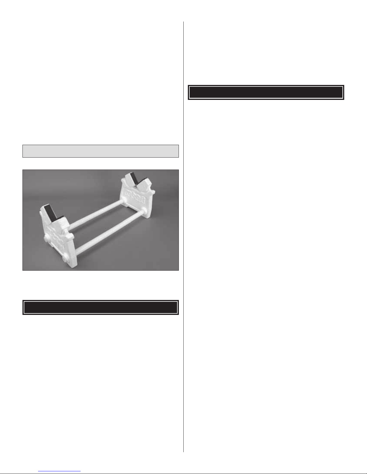
A building stand or cradle comes in handy during the build. We
use the Robart Super Stand II (ROBP1402) for all our projects
in R&D and it can be seen in pictures throughout this manual.
IMPORTANT BUILDING NOTES
• When you see the term test fi t in the instructions, it
means that you should fi rst position the part on the assembly
without using any glue, and then slightly modify or custom
fi t the part as necessary for the best fi t.
• Whenever the term glue is written you should rely upon
your experience to decide what type of glue to use. When
a specifi c type of adhesive works best for that step, the
instructions will make a recommendation.
• Whenever just epoxy is specifi ed you may use either
30-minute (or 45-minute) epoxy or 6-minute epoxy. When
30-minute epoxy is specifi ed it is highly recommended that
you use only 30-minute (or 45-minute) epoxy, because you
will need the working time and/or the additional strength.
Parts may also be ordered directly from Hobby Services by
calling (217) 398-0007, or via facsimile at (217) 398-7721,
but full retail prices and shipping and handling charges will
apply. Illinois and Nevada residents will also be charged
sales tax. If ordering via fax, include a Visa® or MasterCard®
number and expiration date for payment.
Mail parts orders and payments by personal check to:
Hobby Services
3002 N Apollo Drive, Suite 1
Champaign IL 61822
Be certain to specify the order number exactly as listed in
the Replacement Parts List. Payment by credit card or
personal check only; no C.O.D.
If additional assistance is required for any reason contact Product
Support by e-mail at productsupport@greatplanes.com,
or by telephone at (217) 398-8970.
Replacement Parts List
GPMA3180 Wing Set
GPMA3181 Fuse Kit
GPMA3182 Tail Set
GPMA3183 Cowl
GPMA3184 Canopy
GPMA3185 Landing Gear
GPMA3186 Decal Sheet
GPMA2827 Engine Mount
GPMQ4516 2-1/4" Black Plastic Spinner
• Photos and sketches are placed before the step they
refer to. Frequently you can study photos in following steps
to get another view of the same parts.
5
Page 6
COMMON ABBREVIATIONS
METRIC CONVERSIONS
Fuse = Fuselage
Stab = Horizontal Stabilizer
Fin = Vertical Fin
LE = Leading Edge
TE = Trailing Edge
LG = Landing Gear
Ply = Plywood
" = Inches
mm = Millimeters
ESC = Electronic Speed Control
1" = 25.4mm (conversion factor)
1/64" = .4mm
1/32" = .8mm
1/16" = 1.6mm
3/32" = 2.4mm
1/8" = 3.2mm
5/32" = 4.0mm
3/16" = 4.8mm
1/4" = 6.4mm
3/8" = 9.5mm
1/2" = 12.7mm
5/8" = 15.9mm
3/4" = 19.0mm
1" = 25.4mm
2" = 50.8mm
3" = 76.2mm
6" = 152.4mm
12" = 304.8mm
18" = 457.2mm
21" = 533.4mm
24" = 609.6mm
30" = 762.0mm
36" = 914.4mm
6
6
Page 7
KIT INSPECTION
KIT INSPECTION
KIT CONTENTS
Before starting to build, take an inventory of this kit to make sure it is complete and inspect the parts to make sure they
are of acceptable quality. If any parts are missing or are not of acceptable quality, or if you need assistance with assembly,
contact Product Support. When reporting defective or missing parts, use the part names exactly as they are written in
the Kit Contents list.
Great Planes Product Support:
3002 N Apollo Drive, Suite 1
Champaign, IL 61822
Telephone: (217) 398-8970, ext. 5
Fax: (217) 398-7721
E-mail: airsupport@greatplanes.com
KIT CONTENTS
1
3
2
5
6
10
7
6
11
8
4
9
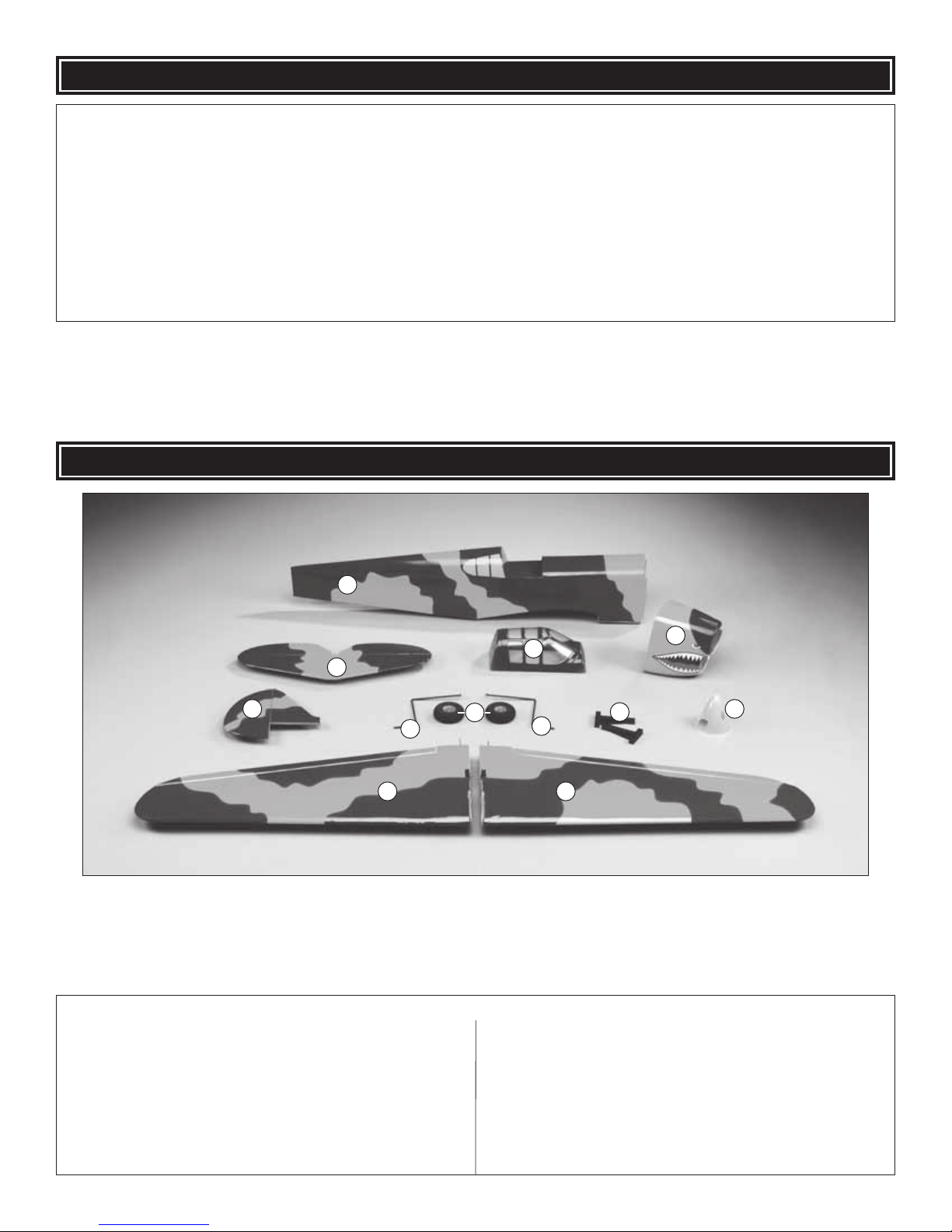
Kit Contents
1 Fuselage
2 Horizontal Stabilizer & Elevators
3 Canopy
4 Cowl
5 Vertical Fin & Rudder
6 Landing Gear (2 pcs.)
7 Wheels (2 pcs.)
8 Engine Mount Halves (2 pcs.)
9 Spinner
10 Right Wing Panel & Aileron
11 Left Wing Panel & Aileron
7
Page 8
PREPARATIONS
❏ 1. If you have not done so already, remove the major parts
of the kit from the box and inspect for damage. If any parts
are damaged or missing, contact Product Support at the
address or telephone number listed in the “Kit Inspection”
section on page 7.
❏ 2. Remove the tape and separate all the control surfaces.
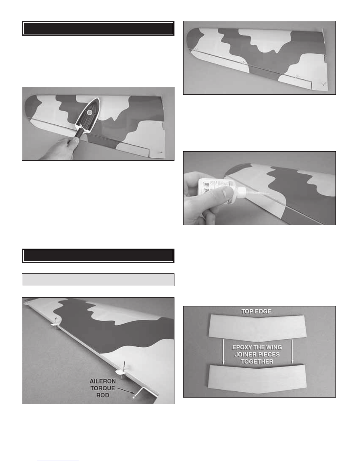
Use a covering iron with a covering sock on medium/high
heat to tighten the covering if necessary. Apply pressure over
sheeted areas to thoroughly bond the cov ering to the wood.
❏ ❏ 2. Roughen the portion of the aileron torque rod that
fi ts into the aileron using 220-grit sandpaper. Apply a thin
coating of epoxy to the torque rod and join the aileron to
the wing by fi tting the torque rod into the hole in the LE of
the aileron and the CA hinges into the slots. Wipe away any
excess epoxy with a cloth dampened with denatured alcohol.
Continue on to the next step before the epoxy cures.
BUILD THE WING
Install the Ailerons
❏ ❏ 3. Remove the pins in the hinges. Adjust the ailerons
so there is a small gap between the LE of the aileron and
the wing. The gap should be small, just enough to see light
through the gap or to slip a piece of paper through. Apply
six drops of thin CA to the top and bottom of each hinge
without using accelerator. After the CA glue has hardened,
confi rm that the ailerons are secure by pulling on them and
defl ecting them up and down.
❏ 4. Repeat steps 2 and 3 for the other wing panel.
❏ 1. T est fi t a CA hinge into each of the hinge slots in the wing
panels and ailerons. If necessary, enlarge the slots with a
hobby knife. When satisfi ed with the fi t, inser t a CA hinge
halfway into each hinge slot in the wing panels. Push a pin
through the middle of each hinge to keep them centered.
❏ 5. Locate the two plywood wing joiners. Mix up a small
amount of epoxy and laminate the two pieces together. Join
the pieces together, being sure the edges are as fl ush as
possible. Use alcohol to wipe away any excess epoxy. Make
note of the top side of the joiner. This should face the top of
the wing panels when installed.
8
8
Page 9
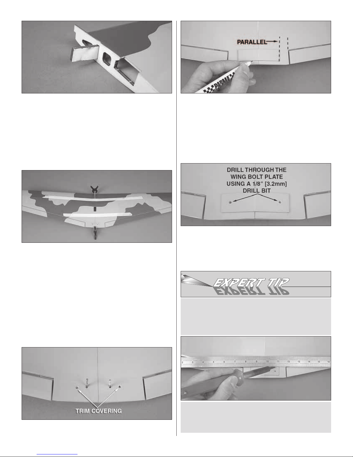
❏ 6. Trim the covering that overlaps onto the root ribs of
each wing panel. T est fi t the joiner into both wing halves . The
joiner should fi t slightly loose to allow room for epoxy. If the
joiner is too snug, sand the face, top or bottom as necessary
for the proper fi t.
❏ 7. Mix approximately 1/2 oz [15cc] of 30-minute epoxy.
Apply a liberal amount of epoxy into the wing joiner pocket
of each wing, the root rib of each wing and the joiner. Insert
the wing joiner into the right wing panel and then slide the
left panel onto the joiner. Push the tw o halves together fi rmly,
making sure there are no gaps anywhere between the wing
panels. Clean any excess epoxy from the wing surface with
alcohol. Hold the wings together with masking tape and
clamps until the epoxy has completely cured.
❏ 9. Align the wing bolt plate over the holes on the
underside of the wing. There is a shallow perforation on the
uncovered side of the wing bolt plate to allow you to bend
the plate to match the dihedral of the wing. Make note of
the orientation of the wing bolt plate on the wing as it is not
perfectly rectangular. The shor t sides of the wing bolt plate
should be parallel with the inside edges of the ailerons. With
the wing bolt plate centered over the holes, use a fi ne, f elt-tip
pen to trace around the plate onto the wing.
❏ 10. Trim the covering just inside your lines. Wipe away the
lines with alcohol and glue the wing bolt plate to the wing.
Continue the wing bolt holes through the wing bolt plate with
a 1/8" [3.2mm] drill bit. A wood bac ker piece while drilling will
help ensure clean-edged holes in the wing bolt plate.
HOW TO CUT COVERING FROM BALSA
❏ 8. Locate and remove the covering from the wing bolt
holes near the TE of the wing.
Use a soldering iron to cut the covering from the wing. The
tip of the soldering iron doesn’t have to be sharp, but a
fi ne-tip does work best. Allow the iron to heat fully.
Use a straightedge to guide the soldering iron at a rate that
will just melt the covering and not burn into the wood. The
hotter the soldering iron, the faster it must travel to melt a
fi ne cut. Peel off the covering.
9
Page 10
Install the Aileron Servo & Pushrods
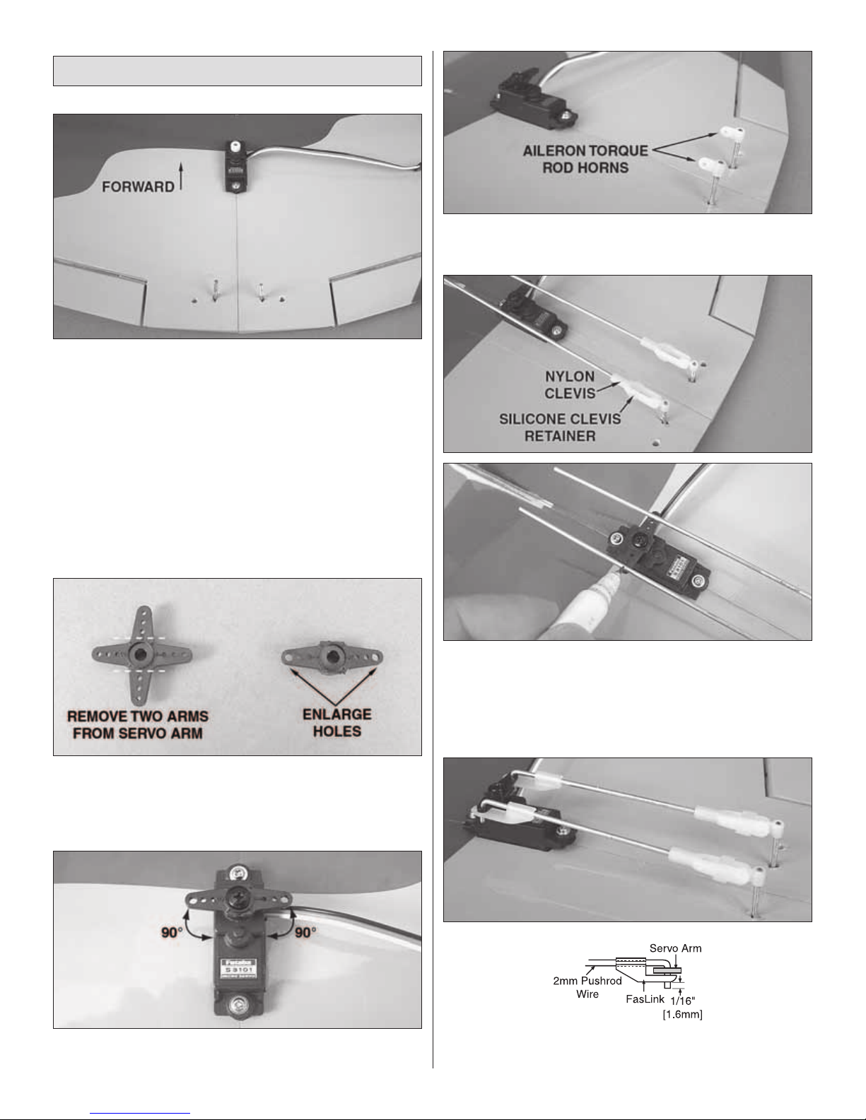
❏ 1. Install the rubber grommets and eyelets that were
included with the servo. Mount the servo in the aileron serv o
bay and drill a 1/16" [1.6mm] hole through each mounting
hole location. Do not drill all the way through the wing!
The holes should be just deep enough to accommodate
the length of the servo mounting screws. Remove the servo
and install and remove a servo mounting screw (included
with your servo) into each hole. Apply a couple drops of thin
CA into the holes to harden the wood. When the CA has
hardened completely, install the servo into the aileron servo
bay using the servo mounting screws with the servo spline
facing forward.
❏ 4. Screw the aileron torque rod horns onto the threaded
ends of the torque rods fl ush with the ends of the rods.
Position the horns to point forward.
❏ 2. Cut two arms from a four-armed servo arm as shown.
Enlarge the outer holes of the remaining arms using a 5/64”
[2mm] drill bit.
❏ 3. Use your radio system to center the servo. Install the
servo arm perpendicular to the servo case.
❏ 5. Screw a nylon cle vis with a silicone clevis retainer onto
each of the 4-3/4” [120mm] pushrods 20 complete turns.
Connect the clevises to the aileron torque rod horns. P osition
the ailerons in the neutral position with tape or small clamps.
Mark on the pushrods where they cross the outer holes in
the aileron servo arm.
❏ 6. Bend the wires 90 degrees at the marks and cut the
excess wire 1/4" [6mm] beyond the bends. Reattach the
10
Page 11

clevises to the torque rod horns and install the 90° bend in
the wires into the outer holes of the servo arms. Secure the
wires with two nylon FasLinks. Confi rm that the ailerons are
both in the neutral position with the servo arm perpendicular
to the servo case. If not, make the necessary adjustments by
threading the clevises up or down the pushrod. When satisfi ed,
slide the silicone clevis retainers to the ends of the clevises .
BUILD THE FUSE
Install the Stab, Elevator & Fin
❏ 1. Locate and remove the covering awa y from the fuse f or
the stab and fi n. Carefully cut a wa y the tail b loc k so the stab
and fi n slots continue all the way to the aft end of the fuse.
❏ 3. Insert the stab into the fuse. Position the stab so it is
centered left and right in the fuse and the tips of the stab are
an equal distance from the wing tips. Trace around the stab
where it meets the fuse with a felt-tip pen.
❏ 2. In order to properly align the stab in the fuse, the wing will
need to be temporarily installed. Attach the wing using two 3mm
x 25mm Phillips machine screws and two 3mm fl at washers.
❏ 4. Cut the covering away 1/16" [1.6mm] inside the lines
you drew.
11
Page 12

❏ 5. Before putting the elevator joiner wire into the stab
slot, trim the covering from the grooves and elevator joiner
wire holes at the LE of the elevator halves. Fit the elevator
joiner wire into the elevators and lay them down on a fl at
work surface. Both elevators should lay fl at. If not, gently
twist the joiner wire until they do (remove the elevator joiner
wire from the elevator halves before bending).
beneath the lines you drew (leave the covering on the TE of
the fi n in place). Use epoxy to glue the fi n in position.
❏ 8. Insert a hinge half way into each hinge slot in the stab
and keep them centered with a pin. Coat the ends of the
elevator joiner wire with epoxy. Working quickly, join the
elevator halves to the stab by fi rst fi tting the joiner wire
ends into the mating holes in the elevators, then fi tting the
CA hinges into place. Before wicking thin CA glue into the
hinges, position the elevator halves so that the elevator tips
are even with the stab tips.
❏ 6. Insert the elevator joiner wire into the back of the stab
slot along with the stab. Stand bac k se ver al feet and vie w the
model from the back. Confi rm that the stab is aligned parallel
with the wing. If necessary , lightly sand the stab poc ket or add
weight to one side of the stab to correct it. When satisfi ed,
glue the stab in place with epoxy. For a strong joint, apply
epoxy to the inside of the stab pock et and onto the stab itself.
Wipe away any excess epoxy with alcohol and let the epoxy
cure undisturbed. Be sure that the epoxy does not contact
the joiner wire.
❏ 7. Fit the vertical fi n into the fuse and trace around it onto
the fi n. Remove the fi n and cut the covering away slightly
❏ 9. Join the rudder to the fuse and fi n with CA hinges.
12
Page 13

Install the Elevator & Rudder
Pushrods & Servos
❏ 1. Locate and remove the covering from the pushrod
exits on both sides of the fuse beneath the stab.
control horn onto the underside of the left elevator half and
position the holes over the hinge line at a slight inward angle
matching the angle of the pushrod. When satisfi ed, mark
the locations for the control horn mounting screws. Dr ill the
holes using a 5/64" [2mm] drill bit and install the control horn
with two 2mm x 15mm machine screws and a control horn
backplate. The screw ends can be cut fl ush with the top of
the control horn backplate.
❏ 3. With the other 19-3/4" [502mm] pushrod, install a control
horn on the right side of the rudder in the same manner.
❏ 2. Insert one of the 19-3/4" [502mm] pushrod wires
through the left pushrod exit slot into the fuse. Hook a nylon
control horn onto the Z-bend in the pushrod wire. Align the
❏ 4. Using the hardware supplied with the servos, install the
elevator and rudder servo into the fuse with the servo splines
facing forw ard. Be sure to reinf orce the servo mounting screw
holes with thin CA.
13
Page 14

Glow Engine, Fuel Tank & Radio Installation
The P-40 Warhawk ARF is designed to be fl own with a .25
glow engine or an out-runner brushless motor. If you plan to
install a brushless motor, skip this section as it only contains
information relevant to installing a glow engine.
❏ 1. Remove the stopper from the fuel tank and shake out
the contents.
❏ 5. Cut three arms from the four-armed servo arms included
with the elevator and rudder servos. Enlarge the outer hole
of each servo arm with a 5/64" [2mm] drill bit. Install a screwlock pushrod connector into the outer hole of each servo
arm. Tighten them to the servo arms with a 2mm fl at washer ,
knurled nut, and threadlocking compound. The nut should be
snug against the washer but still allow the pushrod connector
to rotate freely in the servo arm hole. Slide the pushrod wires
through the screw-lock pushrod connectors and attach the
servo arms to the servos (perpendicular to the ser vo case
pointing out) using the servo arm screws included with the
servos. With the elevators and rudder centered, thread a
3mm set screw with threadlocking compound into the tops
of the pushrod connectors and tighten it against the pushrod
wires. Cut awa y the excess pushrod wires 1/4" [6mm] bey ond
the pushrod connectors.
❏ 2. The fuel tank can be assembled as a two line system
consisting of a vent (pressure) line to the muffl er and a
carb line. Filling and emptying of the tank would need to be
done through the carb line, or an optional fuel fi ll valve (not
included). The tank can also be assembled as a three line
system having a vent line, carb line, and fi ll line. If installing
a fi ll line, puncture the third hole in the top of the stopper
above the sealed off fuel tube hole. The fi ll and carb lines
should extend out 1/2" [13mm] beyond the stopper and the
vent line should be bent upwards and left uncut. With the
tubes installed in the stopper, fi t the stopper plates loosely
in place with the 3mm x 25mm Phillips screw to hold the
assembly together.
❏ 3. Fit the stopper assembly into the tank with the vent line
pointing toward the top of the tank, but not touching. The fuel
tubing and clunk (fuel pickup) on the carb line should almost
14
Page 15

reach the back of the tank but not touch. The clunk must be
able to move freely inside the tank when assembled. Adjust
the length of the fuel tubing accordingly. If you wish to use
the fi ll line to drain the tank, attach a length of fuel tubing and
an additional fuel clunk (not included) to the fi ll line inside the
tank. When satisfi ed, tighten the 3mm x 25mm screw in the
stopper to secure it in place (do not overtighten). Mark the
side of the tank that must face up when installed in the plane,
and we also suggest marking the tubes in the stopper.
❏ 4. Insert the tank into the fuse with the correct side facing
up. The neck of the tank should pass through the hole in
the fi rewall.
❏ 7. Using four 3mm x 16mm machine screws, four 3mm
lock washers and four 3mm fl at washers, attach the engine
mount halves inverted to the fi rewall. The short end of the
engine mount halves should face up.
❏ 5. Cut a piece from the included 6mm x 6mm stick to fi t
between the stringers behind the fuel tank in order to secure
the tank in place as shown. When satisfi ed with the fi t, use
CA to glue the stick in place.
❏ 6. Attach a 6" [150mm] piece of fuel line to each of the
metal tubes in the fuel tank.
❏ 8. P osition the front of the engine driv e washer 3-3/4" [95mm]
from the fi rewall. Mar k the location of the engine mount holes
onto the engine mount halves using a Dead Center™ Hole
Locator (GPMR8130). Remove the engine from the mount and
15
Page 16

use a 3mm tap and drill set to create threads in the four mounting
holes. Attach the engine to the mount using four 3mm x 20mm
SHCS, four 3mm loc k washers , and f our 3mm fl at washers.
❏ 9. Install the throttle servo into the throttle servo bay with
the servo splines facing the same side of the plane as the
throttle arm on the engine.
rubber that fi ts your receiver battery pack and sandwich
it between the pack and the receiver tray. With the pack
centered on the top of the receiver tray (receiver tray shown
upside-down), use a rubber band looped onto the tray tabs
to strap the pack in place as shown.
❏ 10. Cut two 1-1/2" [38mm] pieces from the included 6mm
x 6mm stick. Glue them to the fuse stringers fl ush with the
bottoms approximately 1" [25mm] behind the stick holding
the fuel tank in place.
❏ 11. Prepare the radio installation by locating the glow
engine receiver tray, two rubber bands, receiver, and
receiver battery. You will also need some 1/4" [6mm] or 1/2"
[13mm] foam rubber (not included). Cut a piece of foam
❏ 12. Fit the receiver tray onto the 6mm x 6mm sticks you
glued in step 10. Drill a 5/64" [2mm] hole at each end of the
receiver tray into the stic ks. Attach the tray to the sticks using
two 2.5mm x 10mm self-tapping screws. Cut another piece
of foam rubber to fi t your receiver. Secure the receiver to
the tray with the foam rubber between them using the other
rubber band.
16
Page 17

❏ 13. Drill a 1/8" [3.2mm] hole through the fi rewall inline
with the throttle arm on the engine. Important!! Do not drill
into the fuel tank! The bottom of the tank is 7/8" [22mm]
above the top of the brushless motor cooling hole cutout. To
allow for some error, be sure that your hole is 5/8" [16mm]
or closer to the cooling hole cutout. If in doubt, remove the
tank before drilling your hole. Drill a hole through the second
fuse former inline with the fi rst (a long drill bit is helpful here).
Insert the 1/8" x 9-5/8" [3mm x 245mm] nylon pushrod tube
through the holes. Use CA to glue the tube to the fi rewall.
❏ 15. Install the .039" x 13-3/4" [1mm x 350mm] throttle
pushrod with Z-bend into the outer pushrod tube and
connect the Z-bend to your engine throttle arm (you may
need to remove the arm from the carburetor to do this).
Install a screw-lock pushrod connector into the outer hole of
the throttle servo arm and test fi t it onto the servo . A pushrod
support is provided and can be glued to the third former. Y ou
may need to sand or cut this part to length depending on
the pushrod position. When satisfi ed, slide the support onto
the pushrod tube and glue it in place. Tighten the aft end of
the throttle pushrod in the screw-lock pushrod connector (do
not cut off the excess length of pushrod until you have used
your radio system to center the servo and have made your
adjustments to the pushrod position).
❏ 14. Cut off the excess pushrod tube 1/2" [13mm] behind
the third fuse former.
❏ 16. Run a bead of medium or thick CA glue along the
brushless motor cooling hole cutout lines. Trim the fuel tubing
17
Page 18

to length and connect the vent line to the muffl er and the carb
line to the fuel inlet on the needle valve. A plastic fi ll line plug
has been provided to plug the fi ll line if you installed one.
Out-runner Motor, Battery
& Radio Installation
If you have installed a glo w engine, skip this section as it only
contains information relevant to installing a brushless motor.
❏ 3. Install four 3mm blind nuts into the brushless motor
mount box front piece. Use a 3mm x 10mm screw and a
3mm fl at washer to draw them tight into the holes.
❏ 1. Cut the perforations along the cooling hole and remov e
the cutout.
❏ 4. Attach the brushless motor mount box to the fi rewall
using four 3mm x 16mm machine screws, four 3mm fl at
washers and threadlocking compound.
❏ 5. Install the brushless motor onto the aluminum motor mount
(included with the motor) using four 3mm x 8mm machine
screws (included with the motor) and threadlocking compound.
If you haven’t done so already, install the prop adapter using the
hardware included with the motor. Glue the front adapter piece
to the brushless motor mount box as shown.
❏ 2. Locate the six brushless motor mount box pieces.
Glue the back piece and the four side pieces together as
shown. The tabs on the pieces will all interlock together.
❏ 6. Attach the aluminum motor mount to the brushless
motor mount box using four 3mm x 10mm machine screws,
four 3mm lock washers, and four 3mm fl at washers.
18
Page 19

❏ 7. Cut a 1-1/2" [38mm] piece from the included 1/4" [6mm]
tri-stock. Glue the piece fl ush with the top edge of the fuel
tank opening as shown. This will provide a larger mounting
surface for the battery tray.
❏ 8. Make a battery strap by cutting the hook and loop
material 7-1/4" [184mm] long, overlapping the ends 1-1/2"
[38mm]. The strap can be glued to the underside of the
battery tray with medium or thick CA as shown.
❏ 10. Glue the brushless radio tray to the stringers in the
location shown.
❏ 11. Cut a piece of 1/4" [6mm] or 1/2" [13mm] foam rubber
(not included) to fi t your receiver. Hook one of the included
rubber bands onto the tab on the brushless radio tray and
feed the other end abov e the tray and out of the throttle servo
bay. Place your receiv er and foam rubber onto the brushless
radio tray and loop the rubber band over the receiver and
hook it onto the tab.
❏ 9. Glue the battery tray into the fuse by keying the tab into
the third former and resting the forward end on the fuel tank
opening and the tri-stock you glued in step 7. Apply a liberal
amount of medium or thick CA glue to the mating surfaces to
ensure a very secure battery tray . Cut another piece of tri-stock
and glue it against the aft end of the tray and the f ormer.
❏ 12. Trim the covering from the cooling hole cutout on the
front underside of the fuse.
19
Page 20

❏ 13. Locate the three ESC tra y pieces. Glue the small pieces
together and then glue them into the slot in the large piece.
ESC and brushless out-runner motor, three 4mm male to
3.5mm female bullet connector adapters will be needed.
Great Planes offers these adapters for purchase using part
number (GPMM3123). Secure the ESC to the ESC tray with
a piece of the included double-sided foam servo tape.
❏ 14. Apply a coating of epo xy to the fl at side of the ESC tray
and let it cure undisturbed. The epoxy will provide a smooth
surface for the double-sided tape to adhere to. When the
epoxy is dry, glue the tray onto the top edge of the cooling
hole cutout as shown.
MAKE BATTERY CONNECTOR ADAPTERS
If the Great Planes 4mm male to 3.5mm female bullet
connector adapters are not available, or you would like
to make your own, the assembly procedure and order
numbers for the individual parts are provided below.
A. In order to mak e three adapters for one complete brushless
motor system, you will need Great Planes Gold Plated Bullet
Connectors Female 3.5mm (GPMM3113), Great Planes
Gold Plated Bullet Connectors Male 4mm (GPMM3114),
electrical solder with fl ux, and a soldering iron.
❏ 15. Feed the receiver and battery leads on the ESC
through the left hole in the second former. Connect the ESC
to the receiver and to the motor. If using the recommended
B. Insert the 3.5mm female bullet connector (the end
with the cutout on the side) into the open end of the 4mm
male bullet connector. Shown in the photo above is the
X-Acto® Extra Hands Double Clip (XACR4214). This tool is
extremely useful for small soldering tasks.
20
Page 21

C. With the f emale b ullet in the open end of the male b ullet
and the cutouts in both connectors lined up, apply solder
with fl ux into the cutouts. When applying the solder, it
should appear to fl ow into the joint and around the ends
of the connectors until the joint is coated. Excess solder is
not necessary as it will simply gather at the bottom of the
joint. Use alcohol to wipe the joint clean.
FINISH THE MODEL
Install the Cowl
The cowl installation is shown on the brushless motor power
system. Installing the cowl over a glow engine is the same.
However, in addition to cutting a cooling hole for the engine
head, you will also need to make a hole f or glow plug access, a
hole to access the needle valve, and a cutout for the muffl er .
D . When satisfi ed, slide a piece of heat-shrink tubing over
the adapter up to the base of the male bullet connector.
Use a heat gun or micro torch to shrink the tubing onto the
adapter. If necessar y, trim the excess heat-shrink tubing
from the end of the female bullet connector.
❏ 16. Now is a good time to test the rotation of the motor
before the cowl and prop are installed. Use your radio
system and battery to temporarily power the motor. If the
motor rotates clockwise when viewed from the front, correct
the rotation by choosing any two of the three motor leads
and reverse their positions.
❏ 1. Put four pieces of tape at least 5" [127mm] long onto
the sides of the fuse (two per side) evenly spaced apart
and parallel with the fuse centerline. Make a mark on each
piece of tape in the center of the cowl mounting blocks
that are glued to the edges of the fi rewall. Draw a line using
a straightedge 4" [102mm] long from each mark. Mark the
end of each line as shown. These lines will be used to drill
the mounting holes for the cowl.
❏ 2. Fit the co wl onto the fuse. Temporarily install the spinner
backplate onto the motor shaft. The backplate may need to
be reamed or drilled out to match the shaft size (1/4" [6.4mm]
for the 35-30-1450 out-runner, 1/4" [6.4mm] for the O.S.® .25
FX glow engine). Position the cowl so that the front of it is
3/32" [2.4mm] from the backplate, square and is centered
behind it. When satisfi ed, tape the cowl in place.
21
Page 22

❏ 3. Measure forward 4" [102mm] from the aft marks on the
tape and mark the cowl for the mounting screw locations.
Drill 1/16" [1.6mm] holes through the cowl and through the
cowl mounting blocks at each mark.
you reach the receiver with the tube, feed as much of the
antenna into the tube as possible, then pull the tube with the
antenna inside of it out through the hole.
❏ 2. If you have not done so already, connect the elevator
and rudder servos to the receiver. If y ou have installed a glo w
engine, an optional switch and charge jack (not included)
can be installed onto the side of the fuse wherever there is
free space. Make sure that it does not interfere with any of
the pushrods.
❏ 4. Remove the cowl and tape from the fuse. Cut the
necessary holes in the cowl appropriate for your power
system. The picture shows a cooling hole for the brushless
motor setup. Thread a 2mm x 8mm self-tapping screw into
each cowl hole in the fuse and remove it. Apply a couple
drops of thin CA into each hole to harden the wood. When
the CA has fully cured, install the cowl onto the fuse using
four 2mm x 8mm self-tapping screws.
Final Assembly
❏ 1. The receiver antenna can be taped to the underside of
the fuse. For a cleaner look, we chose to route the antenna
down the inside of the fuse and out the side as shown. To do
this, we used a long scrap piece of pushrod tube we had in
the shop and inserted it through a small hole drilled beneath
the stab. Slide the tube through the hole toward the front of
the plane going through the cutouts in the formers. When
❏ 3. If you have installed a brushless out-runner motor, mix
up a small batch of epoxy and brush a thin coating onto
the battery tray. This will improve the adhesion of the selfadhesive hook and loop material. When the epo xy has cured,
apply the hook side of the included self-adhesive hook and
loop material to the battery tray (cut to length as needed).
❏ 4. Install the loop side of the included self-adhesive hook
and loop material onto the battery pack. Some packs ma y be
able to be moved f orw ard or aft to minimize additional weight
added to the plane for balancing purposes. Longer NiMH
packs may ha v e little room to mo v e along the battery tra y f or
balancing purposes. After the plane is completely assembled,
experiment with the position of the pack if possible when
balancing the plane and mark the optimum position of the
pack onto the battery tray for future reference.
22
Page 23

❏ 5. Attach the canopy to the fuse with R/C 56 canopy
glue. Use masking tape to hold the canop y in place while the
glue dries.
Optional Landing Gear
The P-40 Warhawk ARF includes optional landing gear
for those modelers who choose to sport fl y the model and
would benefi t from using landing gear. The included landing
gear is recommended for paved runways only. If you plan
to fl y the P-40 Warhawk ARF in combat competition, we
suggest omitting the gear for reduced weight and increased
maneuverability.
❏ 6 Install your propeller and the included spinner onto the
motor shaft. Prepare the model f or balancing by installing the
wing using two 3mm x 25mm Phillips machine screws and
two 3mm fl at washers.
❏ 1. Locate and remove the covering from the landing gear
slots on the underside of the wing.
❏ 2. Using f our 3mm wheel collars and four 3mm set scre ws,
temporarily install the wheels onto the landing gear, centering
them on the axles. Tighten the set screws against the axles.
23
Page 24

❏ 3. Remove the wheels and wheel collars and grind fl at
spots on the axles where the set screws made marks from
being tightened. A rotary tool such as a Dremel® with a cutoff wheel or a metal fi le can be used to make the fl at spots.
edges of the tail skid. The washer will prevent the tail skid
from rubbing away when fl ying from a paved runway.
❏ 6. Trim the covering from the long edge of the tail skid.
Locate the slot for the tail skid tab on the underside of the
fuse and remove the cov ering. Test fi t the tail skid into the slot
and mark the forward and aft ends of the tail skid on the fuse.
Remove the tail skid and cut away the covering between the
marks. Glue the tail skid into position using CA glue.
❏ 4. Reinstall the wheels onto the axles using the wheel
collars, set screws, and threadlocking compound. Be sure
that the wheels rotate freely. Oil the wheels at the axles if
necessary. Fit the gear into the slots in the wing. Position
four landing gear straps over the wire, evenly spaced and at
approximately a 45° angle as shown. Mar k the locations for
the strap holes onto the wing and drill 5/64" [2mm] holes at
the marks (be sure not to drill completely through the wing!).
Thread a 2.5mm x 10mm self-tapping screw into each hole
and remove it. Apply a couple drops of thin CA glue to each
hole to harden the wood. Install the straps over the landing
gear using eight 2.5mm x 10mm self-tapping screws.
Apply the Decals
1. Be certain the model is clean and free from oily fi ngerprints
and dust. Prepare a dishpan or small bucket with a mixture
of liquid dish soap and warm water–about one teaspoon of
soap per gallon of water. Submerse the decal in the soap and
water and peel off the paper backing. Note: Ev en though the
decals have a “sticky-back” and are not the water transfer
type, submersing them in soap and water allows accurate
positioning and reduces air bubbles underneath.
❏ 5. Trim the covering from the slot cut into the tail skid.
Glue a 3mm washer into the slot so it is fl ush with the outside
2. P osition decal on the model where desired. Holding the decal
down, use a paper towel to wipe most of the water a w a y.
3. Use a piece of soft balsa or something similar to squeegee
remaining water from under the decal. Apply the rest of the
decals the same way.
24
Page 25

GET THE MODEL READY TO FLY
Note: The throws are measured at the widest part of the
elevators, rudder and ailerons.
Check the Control Directions
❏ 1. Turn on the transmitter and receiver and center the trims.
If necessary, remove the servo arms from the servos and
reposition them so they are centered. Reinstall the screws
that hold on the servo arms.
❏ 2. With the transmitter and receiver still on, check all the
control surfaces to see if they are centered. If necessary , adjust
the clevises on the pushrods to center the control surfaces .
These are the recommended control surface throws:
High Rate Low Rate
ELEVATOR: 1/2" [13mm] up 1/4" [6mm] up
1/2" [13mm] down 1/4" [6mm] down
RUDDER: 3/4" [19mm] right 1/2" [13mm] right
3/4" [19mm] left 1/2" [13mm] left
AILERONS: 3/16" [5mm] up 1/8" [3mm] up
3/16" [5mm] down 1/8" [3mm] down
IMPORTANT: The Combat P-40 Warhawk ARF has been
extensively fl own and tested to arrive at the throws at
which it fl ies best. Flying your model at these throws will
provide you with the greatest chance for successful fi rst
fl ights. If, after you have become accustomed to the way
the Combat P-40 Warhawk ARF fl ies, you would like to
change the throws to suit your taste, that is fi ne. Howev er,
too much control throw could make the model diffi cult to
control, so remember, “more is not always better.”
❏ 3. Make certain that the control surfaces and the throttle
respond in the correct direction as shown in the diagram.
If any of the controls respond in the wrong direction, use
the servo reversing in the transmitter to reverse the servos
connected to those controls. Be certain the control surfaces
have remained centered. Adjust if necessary.
Set the Control Throws
Use a Great Planes AccuThrow (or a ruler) to accurately
measure and set the control throw of each control surface
as indicated in the chart that follows. If your radio does not
have dual rates, we recommend setting the throws at the
low rate setting.
Balance the Model (C.G.)
More than any other factor, the C.G. (balance point) can
have the greatest effect on how a model fl ies, and may
determine whether or not your fi rst fl ight will be successful.
If you value this model and wish to enjo y it for man y fl ights,
DO NOT OVERLOOK THIS IMPORTANT PROCEDURE.
A model that is not properly balanced will be unstable and
possibly unfl yable.
At this stage the model should be in ready-to-fl y condition
with all of the systems in place including the engine or
brushless motor, landing gear, and the radio system (and
battery pack if applicable), but with no fuel.
❏ 1. Use a felt-tip pen or 1/8" [3mm]-wide tape to accurately
mark the C.G. on the top of the wing on both sides of the
fuse. The C.G. is located 1-1/2" [38mm] back from the LE of
the wing where it meets the fuse.
25
Page 26

This is where your model should balance for the fi rst fl ights.
Later, you may wish to experiment by shifting the C.G. up
to 1/4" [6mm] forward or 1/2" [13mm] back to change the
fl ying characteristics. Moving the C.G. forward may impro ve
the smoothness and stability, but the model may then
require more speed for takeoff and make it more diffi cult
to slow for landing. Moving the C.G. aft makes the model
more maneuverable , but could also cause it to become too
diffi cult to control. In any case, start at the recommended
balance point and do not at any time balance the model
outside the specifi ed range.
❏ 2. With the wing attached to the fuse, all parts of the
model installed (ready to fl y) and an empty fuel tank, place
the model upside-down on a Great Planes CG Machine, or
lift it upside-down at the balance point you marked.
Balance the Model Laterally
❏ 1. With the wing level, have an assistant help you lift the
model by the engine propeller shaft and the bottom of the
fuse under the TE of the fi n. Do this several times.
❏ 2. If one wing always drops when you lift the model, it
means that side is heavy. Balance the airplane by adding
weight to the other wing tip. An airplane that has been laterally
balanced will track better in loops and other maneuvers.
PREFLIGHT
Identify Y our Model
No matter if you fl y at an AMA sanctioned R/C club site or
if you fl y somewhere on your own, you should always have
your name, address, telephone number and AMA number
on or inside your model. It is required at all AMA R/C club
fl ying sites and AMA sanctioned fl ying events. Fill out the
identifi cation tag on the decal sheet and place it on or inside
your model.
Charge the Batteries
❏ 3. If the tail drops, the model is “tail heavy” and the battery
pack and/or receiver must be shifted forward or weight must
be added to the nose to balance. If the nose drops, the
model is “nose heavy” and the battery pack and/or receiver
must be shifted aft or weight must be added to the tail to
balance. If possible, relocate the battery pack and receiver
to minimize or eliminate any additional ballast required. If
additional weight is required, nose weight may be easily
added by using a “spinner weight” (GPMQ4645 for the 1 oz.
[28g] weight, or GPMQ4646 for the 2 oz. [57g] weight). If
spinner weight is not practical or is not enough, use Great
Planes (GPMQ4485) “stick-on” lead. A good place to add
stick-on nose weight is to the fi rewall (don’t attach weight
to the cowl–it is not intended to support weight). Begin by
placing incrementally increasing amounts of weight on the
bottom of the fuse over the fi rewall until the model balances.
Once you have determined the amount of weight required,
it can be permanently attached. If required, tail weight may
be added by cutting open the bottom of the fuse and gluing
it permanently inside.
Note: Do not rely upon the adhesive on the back of the lead
weight to permanently hold it in place. Over time, fuel and
exhaust residue may soften the adhesive and cause the
weight to fall off . Use #2 sheet metal screws, RTV silicone or
epoxy to permanently hold the weight in place.
Follow the battery charging instructions that came with your
radio control system to charge the batteries. You should
always charge your transmitter and receiver batteries the night
before you go fl ying, and at other times as recommended by
the radio manufacturer.
CAUTION: Unless the instructions that came with your
radio system state differently, the initial charge on new
transmitter batteries should be done for 15 hours using
the slow-charger that came with the radio system.
This will “condition” the batteries so that the next charge
may be done using the fast-charger of your choice. If the
initial charge is done with a fast-charger the batteries may
not reach their full capacity and you may be fl ying with
batteries that are only partially charged.
❏ 4. IMPORTANT: If you f ound it necessary to add any weight,
recheck the C.G. after the weight has been installed.
26
Page 27

Balance the Propellers
ENGINE / MOTOR SAFETY PRECAUTIONS
Failure to follow these safety precautions may result
in severe injury to yourself and others.
Keep all engine fuel in a safe place, away from high heat,
sparks or fl ames, as fuel is very fl ammable. Do not smoke
near the engine or fuel; and remember that engine exhaust
gives off a great deal of deadly carbon monoxide. Therefore,
do not run the engine in a closed room or garage.
Get help from an experienced pilot when learning to
operate engines.
Carefully balance your propeller and spare propellers before
you fl y . An unbalanced prop can be the single most signifi cant
cause of vibration that can damage your model. Not only
will engine mounting screws and bolts loosen, possibly with
disastrous effect, but vibration may also damage your radio
receiver and battery. Vibration can also cause your fuel to
foam, which will, in turn, cause your engine to run hot or quit.
We use a Top Flite Precision Magnetic Prop Balancer
(TOPQ5700) in the workshop and keep a Great Planes
Fingertip Prop Balancer (GPMQ5000) in our fl ight box.
Ground Check
If the engine is new, follow the engine manufacturer’s
instructions to break-in the engine. After break-in, confi rm
that the engine idles reliably, transitions smoothly and rapidly
to full power and maintains full power–indefi nitely . After you run
the engine on the model, inspect the model closely to make
sure all screws remained tight, the hinges are secure, the prop
is secure and all pushrods and connectors are secure.
Range Check
Ground check the operational range of your r adio before the
fi rst fl ight of the day. With the transmitter antenna collapsed
and the receiver and transmitter on, you should be able to
walk at least 100 feet away from the model and still have
control. Have an assistant stand by your model and, while
you work the controls, tell you what the control surfaces are
doing. Repeat this test with the engine running at various
speeds with an assistant holding the model, using hand
signals to show you what is happening. If the control surfaces
do not respond correctly, do not fl y! Find and correct the
problem fi rst. Look for loose servo connections or broken
wires, corroded wires on old servo connectors, poor solder
joints in your battery pack or a defective cell, or a damaged
receiver crystal from a previous crash.
Use safety glasses when starting or running engines.
Do not run the engine in an area of loose gravel or sand; the
propeller may throw such material in your face or eyes.
Keep your f ace and body as w ell as all spectators a wa y from
the plane of rotation of the propeller as you start and run
the engine.
Keep these items away from the prop: loose clothing, shirt
sleeves, ties, scarves, long hair or loose objects such as
pencils or screwdrivers that may fall out of shirt or jacket
pockets into the prop.
Use a “chicken stick” or electric starter to start the engine.
Do not use your fi ngers to fl ip the propeller. Make certain the
glow plug clip or connector is secure so that it will not pop off
or otherwise get into the running propeller.
Make all engine adjustments from behind the rotating propeller .
The engine gets hot! Do not touch it during or right after
operation. Make sure fuel lines are in good condition so fuel
will not leak onto a hot engine, causing a fi re.
To stop a glow engine, cut off the fuel supply by closing
off the fuel line or following the engine manufacturer’s
recommendations. Do not use hands, fi ngers or any other
body part to try to stop the engine. Do not throw an ything into
the propeller of a running engine.
LITHIUM BATTERY HANDLING & USAGE
WARNING!! Read the entire instruction sheet included with
your battery. Failure to follow all instructions could cause
permanent damage to the battery and its surroundings, and
cause bodily harm!
• ONLY use a LiPo approved charger. NEVER use a NiCd/
NiMH peak charger!
• NEVER charge in excess of 4.20V per cell.
• ONLY charge through the “charge” lead. NEVER charge
through the “discharge” lead.
27
Page 28

• NEVER charge at currents greater than 1C.
• ALWAYS set charger’s output volts to match battery volts.
• ALWAYS charge in a fi reproof location.
• NEVER trickle charge.
• NEVER allow the battery temperature to exceed 150° F
[65° C].
• NEVER disassemble or modify pack wiring in any way or
puncture cells.
• NEVER discharge below 2.5V per cell.
• NEVER place on combustible materials or leave
unattended during charge or discharge.
• ALWAYS KEEP OUT OF REACH OF CHILDREN.
AMA SAFETY CODE (excerpts)
Read and abide by the following excerpts from the Academy
of Model Aeronautics Safety Code. For the complete Safety
Code refer to Model A viation magazine, the AMA web site or
the Code that came with your AMA license.
General
1) I will not fl y my model aircraft in sanctioned events, air shows,
or model fl ying demonstrations until it has been proven to be
airworthy by having been pre viously, successfully fl ight tested.
2) I will not fl y my model aircraft higher than approximately
400 feet within 3 miles of an airport without notifying the
airport operator . I will give right-of-way and avoid fl ying in the
proximity of full-scale aircraft. Where necessary, an observer
shall be utilized to supervise fl ying to avoid having models fl y
in the proximity of full-scale aircraft.
3) Where established, I will abide by the safety rules for the
fl ying site I use, and I will not willfully and deliberately fl y my
models in a careless, reckless and/or dangerous manner.
5) I will not fl y my model unless it is identifi ed with my name
and address or AMA number, on or in the model. Note: This
does not apply to models while being fl own indoors.
7) I will not operate models with pyrotechnics (any device
that explodes, burns, or propels a projectile of any kind).
Radio Control
1) I will have completed a successful radio equipment ground
check before the fi rst fl ight of a new or repaired model.
2) I will not fl y my model aircraft in the presence of spectators
until I become a qualifi ed fl ier, unless assisted by an
experienced helper.
28
3) At all fl ying sites a straight or curved line(s) must be
established in front of which all fl ying takes place with the
other side for spectators. Only personnel involved with fl ying
the aircraft are allowed at or in the front of the fl ight line.
Intentional fl ying behind the fl ight line is prohibited.
4) I will operate my model using only radio control frequencies
currently allowed by the F ederal Communications Commission.
5) I will not knowingly operate my model within three
miles of any pre-existing fl ying site except in accordance
with the frequency sharing agreement listed (in the
complete AMA Safety Code).
9) Under no circumstances may a pilot or other person
touch a powered model in fl ight; nor should an y part of the
model other than the landing gear, intentionally touch
the ground, except while landing.
CHECK LIST
During the last few moments of preparation your mind may
be elsewhere anticipating the excitement of the fi rst fl ight.
Because of this, you may be more likely to overlook certain
checks and procedures that should be performed before the
model is fl own. T o help a v oid this , a check list is provided to
make sure these important areas are not overlooked. Man y
are covered in the instruction manual, so where appropriate,
refer to the manual for complete instructions. Be sure to
check the items off as they are completed.
❏ 1. Check the C.G. according to the measurements
provided in the manual.
❏ 2. Be certain the battery and receiver are securely
mounted in the fuse. Simply stuffi ng them into place
with foam rubber is not suffi cient.
❏ 3. Extend your receiver antenna.
❏ 4. Balance your model laterally as explained in
the instructions.
❏ 5. Use threadlocking compound to secure critical
fasteners such as the set screws that hold the wheel
axles to the struts, screws that hold the carburetor arm
(if applicable), screw-lock pushrod connectors , etc.
❏ 6. Add a drop of oil to the axles so the wheels will
turn freely.
❏ 7. Make sure all hinges are securely glued in place.
❏ 8. Reinforce holes for wood screws with thin CA where
appropriate (servo mounting screws, cowl mounting
screws, etc.).
❏ 9. Confi rm that all controls operate in the correct direction
and the throws are set up according to the manual.
❏ 10. Make sure there are silicone retainers on all the
clevises and that all servo arms are secured to the
servos with the screws included with your radio.
Page 29

❏ 11. Secure connections between servo wires and
Y-connectors or servo extensions, and the connection
between your battery pack and the on/off switch with
vinyl tape, heat-shrink tubing or special clips suitable
for that purpose.
❏ 12. Make sure any servo extension cords you may have
used do not interfere with other systems (servo arms,
pushrods, etc.).
❏ 13. Secure the pressure tap (if used) to the muffl er with
high temp RTV silicone, threadlocking compound or
J.B. Weld.
❏ 14. Make sure the fuel lines are connected and are
not kinked.
❏ 15. Balance your propeller (and spare propellers).
❏ 16. Tighten the propeller nut and spinner.
❏ 17. Place your name, address, AMA number and
telephone number on or inside your model.
❏ 18. Cycle your receiver battery pack (if necessary) and
make sure it is fully charged.
❏ 19. If you wish to photograph your model, do so before
your fi rst fl ight.
❏ 20. Range check your radio when you get to the fl ying fi eld.
CAUTION (THIS APPLIES TO ALL R/C AIRPLANES): If,
while fl ying, you notice an alarming or unusual sound such as
a low-pitched “buzz,” this may indicate control surface fl utter.
Flutter occurs when a control surface (such as an aileron or
elevator) or a fl ying surface (such as a wing or stab) rapidly
vibrates up and down (thus causing the noise). In extreme
cases, if not detected immediately, fl utter can actually cause
the control surface to detach or the fl ying surface to fail, thus
causing loss of control followed by an impending crash. The
best thing to do when fl utter is detected is to slow the model
immediately by reducing power, then land as soon as safely
possible. Identify which surface fl uttered (so the problem
may be resolved) by checking all the servo grommets for
deterioration or signs of vibration. Make certain all pushrod
linkages are secure and free of play. If it fl uttered once, under
similar circumstances it will probably fl utter again unless the
problem is fi xed. Some things which can cause fl utter are;
Excessive hinge gap; Not mounting control horns solidly; Poor
fi t of clevis pin in horn; Side-play of wire pushrods caused
by large bends; Excessive free play in servo gears; Insecure
servo mounting; and one of the most prevalent causes of
fl utter; Flying an ov er-pow ered model at e xcessive speeds.
Takeoff
FLYING
The P-40 Warhawk ARF is a great-fl ying model that fl ies
smoothly and predictably. The P-40 Warhawk ARF does
not, however, possess the self-recovery characteristics of a
primary R/C trainer and should be fl own only by experienced
R/C pilots.
Before you get ready to takeoff, see how the model handles
on the ground by doing a few practice runs at low speeds
on the runway. Hold “up” elevator to keep the tail skid on the
ground. If you need to calm your nerves before the maiden
fl ight, shut the engine down and bring the model back into
the pits. Top off the fuel, then check all fasteners and control
linkages for peace of mind.
Remember to takeoff into the wind. When you’re ready, point
the model straight down the runway, hold a bit of up elevator to
keep the tail on the ground, then gradually adv ance the throttle.
As the model gains speed decrease up elevator allowing the
tail to come off the ground. One of the most important things
to remember with a taildragger is to always be ready to apply
right rudder to counteract engine torque. Gain as much speed
as your runway and fl ying site will practically allow before
gently applying up elevator, lifting the model into the air. At
this moment it is likely that you will need to apply more right
rudder to counteract engine torque. Be smooth on the elevator
stick, allowing the model to establish a gentle climb to a safe
altitude before turning into the traffi c pattern.
Fuel Mixture Adjustments
A fully cowled engine may run at a higher temperature than
an un-cowled engine. For this reason, the fuel mixture should
be richened so the engine runs at about 200 rpm below
peak speed. By running the engine slightly rich, you will help
prevent dead-stick landings caused by overheating.
2929
Page 30

Flight
For reassurance and to keep an eye on other traffi c, it is a
good idea to have an assistant on the fl ight line with you. Tell
him to remind you to throttle back once the plane gets to a
comfortable altitude. While full throttle is usually desir able f or
takeoff, most models fl y more smoothly at reduced speeds.
Take it easy with the P-40 Warhawk ARF for the fi rst few
fl ights, gradually getting acquainted with it as you gain
confi dence. Adjust the trims to maintain straight and level
fl ight. After fl ying around for a while, and while still at a safe
altitude with plenty of fuel, practice slow fl ight and execute
practice landing approaches by reducing the throttle to see
how the model handles at slower speeds. Add power to see
how she climbs as well. Continue to fl y around, executing
various maneuvers and making mental notes (or having y our
assistant write them down) of what trim or C.G. changes may
be required to fi ne tune the model so it fl ies the way you
like. Mind your fl ight time, but use this fi rst fl ight to become
familiar with your model before landing.
Have a ball! But always stay in control
and fl y in a safe manner.
GOOD LUCK AND GREAT FLYING!
Make a copy of this identifi cation tag and put it on or
inside your model.
Landing
To initiate a landing approach, lower the throttle while on the
downwind leg. Allow the nose of the model to pitch downward
to gradually bleed off altitude. Continue to lose altitude, but
maintain airspeed by keeping the nose down as y ou turn onto
the crosswind leg. Make your fi nal turn toward the runway
(into the wind) keeping the nose down to maintain airspeed
and control. Level the attitude when the model reaches the
runway threshold, modulating the throttle as necessary to
maintain your glide path and airspeed. If you are going to
overshoot, smoothly advance the throttle (always ready on
the right rudder to counteract torque) and climb out to make
another attempt. When you’re ready to make your landing
fl are and the model is a foot or so off the deck, smoothly
increase up elevator until it gently touches down. Once the
model is on the runway and has lost fl ying speed, hold up
elevator to place the tail on the ground.
One fi nal note about fl ying your model. Have a goal or fl ight
plan in mind for every fl ight. This can be learning a new
maneuver(s), improving a maneuver(s) you already know,
or learning how the model behaves in certain conditions
(such as on high or low rates). This is not necessarily to
improve your skills (though it is never a bad idea!), but more
importantly so you do not surprise yourself by impulsively
attempting a maneuver and suddenly fi nding that you’v e run
out of time, altitude or airspeed. Every maneuver should be
deliberate, not impulsive. For example, if you’re going to do a
loop, check y our altitude, mind the wind direction (anticipating
rudder corrections that will be required to maintain heading),
remember to throttle back at the top, and make certain you
are on the desired rates (high/low rates). A fl ight plan greatly
reduces the chances of crashing your model just because of
poor planning and impulsive moves. Remember to think.
OTHER ITEMS AVAILABLE
FROM GREAT PLANES
Great Planes Spitfi re .25 GP/EP ARF
With the Spitfi re, your choice of power plant depends on how
you intend to fl y . Use brushless motor power and the optional
landing gear, and you have a lively sport performer for small
areas and big fi elds. Go with glo w (sa y, an O.S.
you can still fl y it for sport...or you can leav e off the gear and
compete in AMA Event 750, Combat Class 2610. Either wa y,
you can be off the bench and in the air in just 4 to 6 hours.
No foam or plastic here – the airframe is built-up wood and
covered in MonoK ote fi lm, with pre-cut decals for scale looks
without scale challenges. Mounts for both glow and electric
systems are included, and aileron servos can be mounted
on the top or bottom of the wing. GPMA1478
30
30
®
.25 FX) and
Page 31

Great Planes ElectriFly™ 35-30-1450 RimFire
™
Out-runner Brushless Motor
• Highly effi cient and vir tually maintenance-free. Bearings
are double-shielded and permanently lubricated.
• Installed, gold-plated bullet connectors compatible with all
ElectriFly ESCs.
• Ideal for brushed-to-brushless upgrades and glow-toelectric conversions!
• Prop adapter, motor mount and hardware included.
Pow ered by rare-earth Neodymium magnets, RimFire out-runner
motors produce explosive acceleration in planes ranging
from park fl yers to 1.60-size giants! Their high-torque design
eliminates the need for a gearbox, making them the simpler,
lighter and less expensive alternative to a brushed motor and
gearbox. Plus, their innovative housing optimizes cooling,
allowing RimFire motors to produce 50% more performance
power than out-runners of similar size. GPMG4600
ElectriFly by Great Planes 3200mAh Power Series LiPo
Battery with Balance Connector
Ideal for scale aircraft, bigger sport aerobats, 3D planes, and
larger electric models, the Pow er Series 3200mAh LiPo pac k
enables you to enjoy the benefi ts of balancing. The cells are
conditioned to last longer, and can be fully charged to 4.20V,
ensuring maximum power from the pack. A LiPo Cell Balancer
(like ElectriFly’s Equinox LiPo Balancer GPMM3160) or a
Balancing Charger is required. GPMP0623
O.S.® .25 FX Engine
The economical .25 FX engine has dual ball bearings for
durability and smooth operation, plus a low crankcase profi le
that allows for a proportionately taller, semi-squared head
to increase cooling fi n area. The needle valve is remotely
mounted for pilot safety, and an O-ring and ratchet spring
minimizes “creep” due to air leaks and vibration. Muffl er is
included; glow plug required. OSMG0525
ElectriFly T riton™2 Charger
The Triton2 DC computerized charger has the versatility
to handle NiCd, NiMH, lithium and lead-acid cells alike. It
can charge LiPo packs with up to 5 cells in series, and the
adjustable charge current is boosted to 7.0A maximum. A
blue backlight allows for easy viewing of the 2 x 16 LCD
screen. GPMM3153
31
Page 32

BUILDING NOTES
Kit Purchased Date: ___________________________
Where Purchased: ____________________________
Date Construction Started: _____________________
FLIGHT LOG
Date Construction Finished: _______________________
Finished Weight: _______________________________
Date of First Flight: ______________________________
 Loading...